JP4850697B2 - Multi-function medical catheter - Google Patents
Multi-function medical catheterDownload PDFInfo
- Publication number
- JP4850697B2 JP4850697B2JP2006508785AJP2006508785AJP4850697B2JP 4850697 B2JP4850697 B2JP 4850697B2JP 2006508785 AJP2006508785 AJP 2006508785AJP 2006508785 AJP2006508785 AJP 2006508785AJP 4850697 B2JP4850697 B2JP 4850697B2
- Authority
- JP
- Japan
- Prior art keywords
- tissue
- medical catheter
- mapping
- ablation
- transducers
- Prior art date
- Legal status (The legal status is an assumption and is not a legal conclusion. Google has not performed a legal analysis and makes no representation as to the accuracy of the status listed.)
- Expired - Fee Related
Links
Images


Classifications
- A—HUMAN NECESSITIES
- A61—MEDICAL OR VETERINARY SCIENCE; HYGIENE
- A61B—DIAGNOSIS; SURGERY; IDENTIFICATION
- A61B5/00—Measuring for diagnostic purposes; Identification of persons
- A61B5/24—Detecting, measuring or recording bioelectric or biomagnetic signals of the body or parts thereof
- A61B5/25—Bioelectric electrodes therefor
- A61B5/279—Bioelectric electrodes therefor specially adapted for particular uses
- A61B5/28—Bioelectric electrodes therefor specially adapted for particular uses for electrocardiography [ECG]
- A61B5/283—Invasive
- A61B5/287—Holders for multiple electrodes, e.g. electrode catheters for electrophysiological study [EPS]
- A—HUMAN NECESSITIES
- A61—MEDICAL OR VETERINARY SCIENCE; HYGIENE
- A61B—DIAGNOSIS; SURGERY; IDENTIFICATION
- A61B5/00—Measuring for diagnostic purposes; Identification of persons
- A61B5/05—Detecting, measuring or recording for diagnosis by means of electric currents or magnetic fields; Measuring using microwaves or radio waves
- A61B5/053—Measuring electrical impedance or conductance of a portion of the body
- A61B5/0538—Measuring electrical impedance or conductance of a portion of the body invasively, e.g. using a catheter
- A—HUMAN NECESSITIES
- A61—MEDICAL OR VETERINARY SCIENCE; HYGIENE
- A61B—DIAGNOSIS; SURGERY; IDENTIFICATION
- A61B18/00—Surgical instruments, devices or methods for transferring non-mechanical forms of energy to or from the body
- A61B18/04—Surgical instruments, devices or methods for transferring non-mechanical forms of energy to or from the body by heating
- A61B18/12—Surgical instruments, devices or methods for transferring non-mechanical forms of energy to or from the body by heating by passing a current through the tissue to be heated, e.g. high-frequency current
- A61B18/14—Probes or electrodes therefor
- A61B18/1492—Probes or electrodes therefor having a flexible, catheter-like structure, e.g. for heart ablation
- A—HUMAN NECESSITIES
- A61—MEDICAL OR VETERINARY SCIENCE; HYGIENE
- A61B—DIAGNOSIS; SURGERY; IDENTIFICATION
- A61B8/00—Diagnosis using ultrasonic, sonic or infrasonic waves
- A61B8/12—Diagnosis using ultrasonic, sonic or infrasonic waves in body cavities or body tracts, e.g. by using catheters
- A—HUMAN NECESSITIES
- A61—MEDICAL OR VETERINARY SCIENCE; HYGIENE
- A61M—DEVICES FOR INTRODUCING MEDIA INTO, OR ONTO, THE BODY; DEVICES FOR TRANSDUCING BODY MEDIA OR FOR TAKING MEDIA FROM THE BODY; DEVICES FOR PRODUCING OR ENDING SLEEP OR STUPOR
- A61M25/00—Catheters; Hollow probes
- A61M25/01—Introducing, guiding, advancing, emplacing or holding catheters
- A61M25/0105—Steering means as part of the catheter or advancing means; Markers for positioning
- A61M25/0133—Tip steering devices
- A—HUMAN NECESSITIES
- A61—MEDICAL OR VETERINARY SCIENCE; HYGIENE
- A61N—ELECTROTHERAPY; MAGNETOTHERAPY; RADIATION THERAPY; ULTRASOUND THERAPY
- A61N1/00—Electrotherapy; Circuits therefor
- A61N1/02—Details
- A61N1/04—Electrodes
- A61N1/05—Electrodes for implantation or insertion into the body, e.g. heart electrode
- A61N1/056—Transvascular endocardial electrode systems
- A—HUMAN NECESSITIES
- A61—MEDICAL OR VETERINARY SCIENCE; HYGIENE
- A61B—DIAGNOSIS; SURGERY; IDENTIFICATION
- A61B17/00—Surgical instruments, devices or methods
- A61B2017/00017—Electrical control of surgical instruments
- A61B2017/00022—Sensing or detecting at the treatment site
- A61B2017/00106—Sensing or detecting at the treatment site ultrasonic
- A—HUMAN NECESSITIES
- A61—MEDICAL OR VETERINARY SCIENCE; HYGIENE
- A61B—DIAGNOSIS; SURGERY; IDENTIFICATION
- A61B18/00—Surgical instruments, devices or methods for transferring non-mechanical forms of energy to or from the body
- A61B2018/00053—Mechanical features of the instrument of device
- A61B2018/0016—Energy applicators arranged in a two- or three dimensional array
- A—HUMAN NECESSITIES
- A61—MEDICAL OR VETERINARY SCIENCE; HYGIENE
- A61B—DIAGNOSIS; SURGERY; IDENTIFICATION
- A61B18/00—Surgical instruments, devices or methods for transferring non-mechanical forms of energy to or from the body
- A61B2018/00315—Surgical instruments, devices or methods for transferring non-mechanical forms of energy to or from the body for treatment of particular body parts
- A61B2018/00345—Vascular system
- A61B2018/00351—Heart
- A—HUMAN NECESSITIES
- A61—MEDICAL OR VETERINARY SCIENCE; HYGIENE
- A61B—DIAGNOSIS; SURGERY; IDENTIFICATION
- A61B18/00—Surgical instruments, devices or methods for transferring non-mechanical forms of energy to or from the body
- A61B2018/00571—Surgical instruments, devices or methods for transferring non-mechanical forms of energy to or from the body for achieving a particular surgical effect
- A61B2018/00577—Ablation
- A—HUMAN NECESSITIES
- A61—MEDICAL OR VETERINARY SCIENCE; HYGIENE
- A61B—DIAGNOSIS; SURGERY; IDENTIFICATION
- A61B18/00—Surgical instruments, devices or methods for transferring non-mechanical forms of energy to or from the body
- A61B2018/00636—Sensing and controlling the application of energy
- A61B2018/00642—Sensing and controlling the application of energy with feedback, i.e. closed loop control
- A61B2018/00654—Sensing and controlling the application of energy with feedback, i.e. closed loop control with individual control of each of a plurality of energy emitting elements
- A—HUMAN NECESSITIES
- A61—MEDICAL OR VETERINARY SCIENCE; HYGIENE
- A61B—DIAGNOSIS; SURGERY; IDENTIFICATION
- A61B18/00—Surgical instruments, devices or methods for transferring non-mechanical forms of energy to or from the body
- A61B2018/00636—Sensing and controlling the application of energy
- A61B2018/00773—Sensed parameters
- A61B2018/00839—Bioelectrical parameters, e.g. ECG, EEG
- A—HUMAN NECESSITIES
- A61—MEDICAL OR VETERINARY SCIENCE; HYGIENE
- A61B—DIAGNOSIS; SURGERY; IDENTIFICATION
- A61B18/00—Surgical instruments, devices or methods for transferring non-mechanical forms of energy to or from the body
- A61B18/04—Surgical instruments, devices or methods for transferring non-mechanical forms of energy to or from the body by heating
- A61B18/12—Surgical instruments, devices or methods for transferring non-mechanical forms of energy to or from the body by heating by passing a current through the tissue to be heated, e.g. high-frequency current
- A61B18/1206—Generators therefor
- A61B2018/124—Generators therefor switching the output to different electrodes, e.g. sequentially
- A—HUMAN NECESSITIES
- A61—MEDICAL OR VETERINARY SCIENCE; HYGIENE
- A61B—DIAGNOSIS; SURGERY; IDENTIFICATION
- A61B18/00—Surgical instruments, devices or methods for transferring non-mechanical forms of energy to or from the body
- A61B18/04—Surgical instruments, devices or methods for transferring non-mechanical forms of energy to or from the body by heating
- A61B18/12—Surgical instruments, devices or methods for transferring non-mechanical forms of energy to or from the body by heating by passing a current through the tissue to be heated, e.g. high-frequency current
- A61B18/14—Probes or electrodes therefor
- A61B2018/1467—Probes or electrodes therefor using more than two electrodes on a single probe
- A—HUMAN NECESSITIES
- A61—MEDICAL OR VETERINARY SCIENCE; HYGIENE
- A61B—DIAGNOSIS; SURGERY; IDENTIFICATION
- A61B90/00—Instruments, implements or accessories specially adapted for surgery or diagnosis and not covered by any of the groups A61B1/00 - A61B50/00, e.g. for luxation treatment or for protecting wound edges
- A61B90/06—Measuring instruments not otherwise provided for
- A61B2090/064—Measuring instruments not otherwise provided for for measuring force, pressure or mechanical tension
- A61B2090/065—Measuring instruments not otherwise provided for for measuring force, pressure or mechanical tension for measuring contact or contact pressure
- A—HUMAN NECESSITIES
- A61—MEDICAL OR VETERINARY SCIENCE; HYGIENE
- A61B—DIAGNOSIS; SURGERY; IDENTIFICATION
- A61B90/00—Instruments, implements or accessories specially adapted for surgery or diagnosis and not covered by any of the groups A61B1/00 - A61B50/00, e.g. for luxation treatment or for protecting wound edges
- A61B90/39—Markers, e.g. radio-opaque or breast lesions markers
- A61B2090/3925—Markers, e.g. radio-opaque or breast lesions markers ultrasonic
- A61B2090/3929—Active markers
- A—HUMAN NECESSITIES
- A61—MEDICAL OR VETERINARY SCIENCE; HYGIENE
- A61B—DIAGNOSIS; SURGERY; IDENTIFICATION
- A61B90/00—Instruments, implements or accessories specially adapted for surgery or diagnosis and not covered by any of the groups A61B1/00 - A61B50/00, e.g. for luxation treatment or for protecting wound edges
- A61B90/39—Markers, e.g. radio-opaque or breast lesions markers
- A61B2090/3954—Markers, e.g. radio-opaque or breast lesions markers magnetic, e.g. NMR or MRI
- A61B2090/3958—Markers, e.g. radio-opaque or breast lesions markers magnetic, e.g. NMR or MRI emitting a signal
- A—HUMAN NECESSITIES
- A61—MEDICAL OR VETERINARY SCIENCE; HYGIENE
- A61B—DIAGNOSIS; SURGERY; IDENTIFICATION
- A61B90/00—Instruments, implements or accessories specially adapted for surgery or diagnosis and not covered by any of the groups A61B1/00 - A61B50/00, e.g. for luxation treatment or for protecting wound edges
- A61B90/39—Markers, e.g. radio-opaque or breast lesions markers
- A61B2090/397—Markers, e.g. radio-opaque or breast lesions markers electromagnetic other than visible, e.g. microwave
- A61B2090/3975—Markers, e.g. radio-opaque or breast lesions markers electromagnetic other than visible, e.g. microwave active
- A—HUMAN NECESSITIES
- A61—MEDICAL OR VETERINARY SCIENCE; HYGIENE
- A61B—DIAGNOSIS; SURGERY; IDENTIFICATION
- A61B8/00—Diagnosis using ultrasonic, sonic or infrasonic waves
- A61B8/08—Clinical applications
- A61B8/0883—Clinical applications for diagnosis of the heart
- A—HUMAN NECESSITIES
- A61—MEDICAL OR VETERINARY SCIENCE; HYGIENE
- A61B—DIAGNOSIS; SURGERY; IDENTIFICATION
- A61B8/00—Diagnosis using ultrasonic, sonic or infrasonic waves
- A61B8/44—Constructional features of the ultrasonic, sonic or infrasonic diagnostic device
- A61B8/4444—Constructional features of the ultrasonic, sonic or infrasonic diagnostic device related to the probe
- A61B8/4472—Wireless probes
- A—HUMAN NECESSITIES
- A61—MEDICAL OR VETERINARY SCIENCE; HYGIENE
- A61M—DEVICES FOR INTRODUCING MEDIA INTO, OR ONTO, THE BODY; DEVICES FOR TRANSDUCING BODY MEDIA OR FOR TAKING MEDIA FROM THE BODY; DEVICES FOR PRODUCING OR ENDING SLEEP OR STUPOR
- A61M25/00—Catheters; Hollow probes
- A61M25/01—Introducing, guiding, advancing, emplacing or holding catheters
- A61M25/0105—Steering means as part of the catheter or advancing means; Markers for positioning
- A61M25/0133—Tip steering devices
- A61M2025/0161—Tip steering devices wherein the distal tips have two or more deflection regions
- A—HUMAN NECESSITIES
- A61—MEDICAL OR VETERINARY SCIENCE; HYGIENE
- A61N—ELECTROTHERAPY; MAGNETOTHERAPY; RADIATION THERAPY; ULTRASOUND THERAPY
- A61N7/00—Ultrasound therapy
- A61N2007/0078—Ultrasound therapy with multiple treatment transducers
- A—HUMAN NECESSITIES
- A61—MEDICAL OR VETERINARY SCIENCE; HYGIENE
- A61N—ELECTROTHERAPY; MAGNETOTHERAPY; RADIATION THERAPY; ULTRASOUND THERAPY
- A61N7/00—Ultrasound therapy
- A61N7/02—Localised ultrasound hyperthermia
Landscapes
- Health & Medical Sciences (AREA)
- Life Sciences & Earth Sciences (AREA)
- Engineering & Computer Science (AREA)
- Heart & Thoracic Surgery (AREA)
- Animal Behavior & Ethology (AREA)
- Biomedical Technology (AREA)
- General Health & Medical Sciences (AREA)
- Public Health (AREA)
- Veterinary Medicine (AREA)
- Surgery (AREA)
- Molecular Biology (AREA)
- Medical Informatics (AREA)
- Biophysics (AREA)
- Physics & Mathematics (AREA)
- Nuclear Medicine, Radiotherapy & Molecular Imaging (AREA)
- Cardiology (AREA)
- Pathology (AREA)
- Radiology & Medical Imaging (AREA)
- Physiology (AREA)
- Anesthesiology (AREA)
- Pulmonology (AREA)
- Plasma & Fusion (AREA)
- Otolaryngology (AREA)
- Vascular Medicine (AREA)
- Hematology (AREA)
- Surgical Instruments (AREA)
- Ultra Sonic Daignosis Equipment (AREA)
- Measuring And Recording Apparatus For Diagnosis (AREA)
Description
Translated fromJapanese (関連出願の引用)
本出願は、係属中の米国特許出願番号10/305,256(2002年11月25日に出願された、発明の名称「ULTRASOUND−GUIDED ABLATION CATHETER AND METHODS OF USE」)の一部継続(CIP)出願である;米国特許出願番号10/305,256は、米国特許出願番号09/750,439(2000年12月28日に出願され、米国特許第6,508,765号として2003年1月21日に発行された)の継続出願である;これは、米国特許出願番号09/227,281(1999年1月6日に出願され、米国特許第6,206,831 B1号として2001年3月27日に発行された)の継続出願である。これらの完全な開示は、あらゆる目的のため、本明細書において参考として援用される。(Citation of related application)
This application is a continuation-in-part (CIP) of pending US Patent Application No. 10 / 305,256 (filed on November 25, 2002, entitled “ULTRASOUND-GUIDED ABLATION CATHETER AND METHODS OF USE”). U.S. Patent Application No. 10 / 305,256 is filed on U.S. Patent Application No. 09 / 750,439 (filed Dec. 28, 2000, U.S. Pat. No. 6,508,765, Jan. 21, 2003). This is a continuation application of US patent application Ser. No. 09 / 227,281 (filed Jan. 6, 1999, U.S. Pat. No. 6,206,831 B1, March 2001). This is a continuation application issued on the 27th. These full disclosures are incorporated herein by reference for all purposes.
(発明の背景)
本発明は、一般的に、医療用カテーテルの分野に関し、より詳細には、マッピングするため、配向するため、および/または種々の症状のための処置を提供するために適合された、多機能医療用カテーテルに関する。(Background of the Invention)
The present invention relates generally to the field of medical catheters, and more particularly multifunctional medical, adapted to map, orient, and / or provide treatment for various conditions. The present invention relates to a catheter.
医師らは、今日、身体の内部領域内に接近することによって最もうまく実施される医療手順において、カテーテルを活用する。例えば、電気外科手術治療において、切除は、心臓律動障害を処置するために使用される。このような治療は、例えば、心臓組織において所望の位置に損傷を形成して望ましくない電気経路を妨害することによって、心房細動を処置するために使用され得る。 Physicians today take advantage of catheters in medical procedures that are best performed by approaching the interior region of the body. For example, in electrosurgical therapy, resection is used to treat cardiac rhythm disorders. Such therapy can be used, for example, to treat atrial fibrillation by creating damage at a desired location in the heart tissue and obstructing undesired electrical pathways.
これらの手順の間、医師は、代表的に、最初に患者の心臓の電気活動をマッピングし、あらゆる異常の位置の決定を助ける。次いで、医師は、主静脈もしくは主動脈を通じて、処置されるべき心臓の内部領域へとカテーテルを進める。カテーテルの遠位端上に保有された切除素子は、切除されるべき組織の近くに位置決めされる。このような処置のため、切除エネルギーの送達は、組織損傷および凝固形成の発生を避けるために綿密に管理されなければならない。さらに、切除カテーテルは、処置されるべき組織に隣接し、そして好ましくはその組織に接触して、正確に位置決めされ、損傷が適切に配置されることを保証しなければならない。 During these procedures, the physician typically first maps the electrical activity of the patient's heart to help determine the location of any abnormalities. The physician then advances the catheter through the main vein or main artery to the internal region of the heart to be treated. An ablation element carried on the distal end of the catheter is positioned near the tissue to be ablated. For such a procedure, delivery of ablation energy must be carefully managed to avoid the occurrence of tissue damage and coagulation formation. In addition, the ablation catheter must be adjacent to and preferably in contact with the tissue to be treated to ensure that it is accurately positioned and that the lesion is properly positioned.
診断および治療手順(例えば、電気外科手術治療)を行う医師およびスタッフは、代表的に、切除カテーテルの位置決めを補助するための画像化システムを必要とする。小型経食道超音波心エコー検査(mini−TEE)プローブが利用可能であるが、しかし、これらのプローブは、嚥下されなければならないか、または患者の喉に挿入されなければならない。患者が十分に麻酔されていない場合、このようなプローブに、患者は十分に耐容性を示さない。さらに、これらのプローブは、かなり大きく(すなわち、直径20フレンチ)、かつ複雑なトランスデューサ構造を使用する可能性があり、切除素子による組織接触を検出することにおいて困難を伴い得る。さらに、マッピング、画像化および処置は、多くの場合、複数の装置またはカテーテルを必要とし、複雑な手順、および複数のカテーテルの患者への導入または再導入を伴う。改善が望ましい。 Physicians and staff performing diagnostic and therapeutic procedures (eg, electrosurgical treatment) typically require an imaging system to assist in positioning the ablation catheter. Small transesophageal echocardiography (mini-TEE) probes are available, but these probes must be swallowed or inserted into the patient's throat. If the patient is not sufficiently anesthetized, the patient will not be well tolerated with such a probe. In addition, these probes can be quite large (ie, 20 French in diameter) and use complex transducer structures, which can be difficult in detecting tissue contact by the ablation element. Furthermore, mapping, imaging and treatment often require multiple devices or catheters, involving complex procedures and introduction or reintroduction of multiple catheters into a patient. Improvement is desirable.
(発明の概要)
本発明は、多機能医療用カテーテル、システムおよびその使用のための方法を提供する。いくつかの実施形態において、上記カテーテルは、超音波誘導式切除カテーテルを備える。本発明のカテーテルおよびシステムは、心房細動の処置のために要求されるような心臓組織の切除前の、切除カテーテルの正確な位置決めのために特に有用である。さらに、いくつかの実施形態の機能性は、単一のカテーテルが、組織マッピング、組織配向、組織画像化、および/または組織処置(切除を含む)のために使用されることを可能にする。本発明のシステムのいくつかは、上記カテーテルの遠位端においてトランスデューサを使用して、切除素子が切除されるべき組織と接触しているか否かを操作者が決定するのを補助する。非切除カテーテルもまた、本発明に含まれ、このようなカテーテルは、組織マッピング、組織配向、および/または組織画像化機能を提供する。(Summary of Invention)
The present invention provides a multifunction medical catheter, system and method for its use. In some embodiments, the catheter comprises an ultrasound guided ablation catheter. The catheters and systems of the present invention are particularly useful for accurate positioning of an ablation catheter prior to excision of heart tissue as required for atrial fibrillation procedures. Further, the functionality of some embodiments allows a single catheter to be used for tissue mapping, tissue orientation, tissue imaging, and / or tissue treatment (including ablation). Some of the systems of the present invention use a transducer at the distal end of the catheter to assist the operator in determining whether the ablation element is in contact with the tissue to be ablated. Non-ablated catheters are also included in the present invention, and such catheters provide tissue mapping, tissue orientation, and / or tissue imaging functions.
特定の一実施形態において、本発明の医療用カテーテルは、近位端および遠位端を有する可撓性細長本体を備える。複数の相隔する電極は、上記遠位端近くで上記可撓性本体に作動可能に取り付けられている。上記電極の少なくともいくつかは、組織をマッピングするために適合されている。上記カテーテルは、上記電極の少なくともいくつかの間に配置された複数の組織配向検出器を備える。この様式において、上記医療用カテーテルは、組織マッピング機能および組織配向機能の両方の能力を有する。いくつかの実施形態において、上記電極の少なくとも一つは、組織の所望の部位を切除するために適合され、上記カテーテルは、組織切除または他の処置の能力を有する。 In one particular embodiment, the medical catheter of the present invention comprises a flexible elongate body having a proximal end and a distal end. A plurality of spaced apart electrodes are operably attached to the flexible body near the distal end. At least some of the electrodes are adapted for mapping tissue. The catheter includes a plurality of tissue orientation detectors disposed between at least some of the electrodes. In this manner, the medical catheter has the capability of both a tissue mapping function and a tissue orientation function. In some embodiments, at least one of the electrodes is adapted to ablate a desired site in tissue, and the catheter has tissue ablation or other treatment capabilities.
いくつかの局面では、上記電極の少なくとも一つは、マッピングおよび切除の両方のために適合されている。いくつかの局面では、切除のために適合された上記電極は、それらに隣接した少なくとも一つの組織配向検出器を有する。このような様式で、上記検出器は、切除前に、切除電極の配置を決定するのを助ける。例えば、上記検出器は、組織接触の決定、組織までの距離の検出、組織に対する3次元位置の検出などをするように作動し得る。いくつかの局面では、上記電極の少なくとも一つは、上記遠位端の先端に接続された先端電極を備える。 In some aspects, at least one of the electrodes is adapted for both mapping and ablation. In some aspects, the electrodes adapted for ablation have at least one tissue orientation detector adjacent to them. In this manner, the detector helps determine the placement of the ablation electrode prior to ablation. For example, the detector may be operative to determine tissue contact, detect distance to the tissue, detect a three dimensional position relative to the tissue, and the like. In some aspects, at least one of the electrodes comprises a tip electrode connected to the tip of the distal end.
上記組織配向検出器は、本発明の範囲内において、種々の構造を有し得る。例えば、一実施形態において、この組織配向検出器は、複数のトランスデューサを備える。特定の実施形態において、上記トランスデューサの少なくともいくつかは、超音波トランスデューサを備える。あるいは、または加えて、上記トランスデューサの少なくともいくつかは、電気トランスデューサ、磁気トランスデューサまたは電磁追跡トランスデューサである。 The tissue orientation detector may have various structures within the scope of the present invention. For example, in one embodiment, the tissue orientation detector comprises a plurality of transducers. In certain embodiments, at least some of the transducers comprise ultrasonic transducers. Alternatively or additionally, at least some of the transducers are electrical transducers, magnetic transducers or electromagnetic tracking transducers.
本発明は、本発明に従う例示的医療用カテーテルシステムを、さらに提供する。一実施形態において、このシステムは、本明細書において詳述されるような、上記複数の電極および組織配向検出器に接続されたコントローラを有する医療用カテーテルを備える。一局面において、上記コントローラは、上記複数の電極によって行われる組織マッピング機能を制御するために適合されている。特定の局面において、上記組織マッピング機能は、非接触式組織マッピング機能を包含する。一局面において、上記コントローラは、上記組織マッピング機能の結果に基づいて組織切除パターンを決定するために、さらに適合されている。 The present invention further provides an exemplary medical catheter system according to the present invention. In one embodiment, the system comprises a medical catheter having a controller connected to the plurality of electrodes and tissue orientation detector as detailed herein. In one aspect, the controller is adapted to control a tissue mapping function performed by the plurality of electrodes. In a specific aspect, the tissue mapping function includes a non-contact tissue mapping function. In one aspect, the controller is further adapted to determine a tissue ablation pattern based on the results of the tissue mapping function.
別の局面において、上記医療用カテーテルシステムコントローラは、上記組織配向検出器からの複数の信号を受信するため、および組織に対する上記細長本体の配向を決定するために適合されている。 In another aspect, the medical catheter system controller is adapted to receive a plurality of signals from the tissue orientation detector and to determine the orientation of the elongated body relative to tissue.
いくつかの実施形態において、上記医療用カテーテルシステムは、デジタル化システム、および/または上記複数の電極に電気的に接続されたRF発生器をさらに備える。上記デジタル化システムは、組織のデジタル画像を作製するために適合されている。これらの画像は、上記電極および/または上記検出器によって受信されたデータに部分的に基づき得る。上記RF発生器は、一以上の電極を用いて、組織の切除などを容易にし得る。 In some embodiments, the medical catheter system further comprises a digitization system and / or an RF generator electrically connected to the plurality of electrodes. The digitizing system is adapted for producing a digital image of tissue. These images may be based in part on the data received by the electrodes and / or the detector. The RF generator may facilitate excision of tissue using one or more electrodes.
本発明は、医療用カテーテルを組織に対して正確に位置決めする例示的な方法を、さらに提供する。このような一実施形態において、上記方法は、医療用カテーテルシステム(例えば、本明細書において詳述されるシステムの一つ)を提供する工程を包含する。上記方法は、患者に上記可撓性細長本体を挿入する工程、上記電極の少なくともいくつかを用いて組織の電気的プロフィールをマッピングする工程、および上記組織配向検出器を用いてこの細長本体を組織に近接するように位置決めする工程をさらに包含する。この位置決めする工程は、組織の電気的プロフィールに部分的に基づく。 The present invention further provides an exemplary method for accurately positioning a medical catheter relative to tissue. In one such embodiment, the method includes providing a medical catheter system (eg, one of the systems detailed herein). The method includes inserting the flexible elongate body into a patient, mapping the electrical profile of the tissue using at least some of the electrodes, and using the tissue orientation detector to tissue the elongate body. The method further includes a step of positioning so as to be in proximity to. This positioning step is based in part on the electrical profile of the tissue.
一局面において、上記方法は、上記コントローラが、上記組織配向検出器の少なくとも一つが所望の組織領域に接触していることを決定した場合に、上記電極の少なくとも一つを駆動してこの組織の所望の領域を切除する工程をさらに包含する。特定の局面において、上記コントローラが、上記電極に隣接して位置する上記組織配向検出器の一つが所望の組織領域に接触していることを決定した場合、上記電極のすぐ近位に位置する上記組織配向検出器がこの組織に接触している場合、および/または近位方向と遠位方向との両方において上記電極に最も近接する上記組織配向検出器がこの組織に接触している場合に、上記電極の少なくとも一つが駆動されて、この組織の所望の領域を切除する。この様式において、切除前に組織接触が決定され得る。 In one aspect, the method drives the at least one of the electrodes when the controller determines that at least one of the tissue orientation detectors is in contact with a desired tissue region. The method further includes the step of excising the desired region. In certain aspects, if the controller determines that one of the tissue orientation detectors located adjacent to the electrode is in contact with a desired tissue region, the controller is located immediately proximal to the electrode. When the tissue orientation detector is in contact with the tissue and / or when the tissue orientation detector closest to the electrode in both proximal and distal directions is in contact with the tissue, At least one of the electrodes is activated to ablate a desired region of the tissue. In this manner, tissue contact can be determined prior to resection.
一局面において、本発明の方法は、組織の電気的プロフィールに基づいて処置されるべき組織の所望の領域を同定する工程を、さらに包含する。本明細書において考察されるように、上記マッピングは、いくつかの実施形態において、上記電気的プロフィールを得るためか、または上記電気的プロフィールを得るのを助けるための、非接触式マッピングを包含し得る。 In one aspect, the method of the invention further comprises identifying a desired region of tissue to be treated based on the electrical profile of the tissue. As discussed herein, the mapping includes, in some embodiments, non-contact mapping to obtain the electrical profile or to help obtain the electrical profile. obtain.
本発明に従って、患者内でカテーテルを正確に位置決めする別の方法において、このカテーテルは、上記患者内に挿入される。次いで、上記方法は、上記複数の相隔する電極の少なくともいくつかを用いて患者の組織をマッピングして、組織プロフィールを作製する工程を包含する。この組織プロフィールは、例えば、組織における複数の電気経路のマップまたは他の表現を包含し得る。処置されるべき組織領域は、少なくとも部分的にこの組織プロフィールを使用することによって同定される。上記細長本体は、トランスデューサを用いて位置決めされ、これによって上記電極の少なくとも一つは、上記組織領域と近接する。一局面において、上記細長本体の位置決めは、3次元配置の位置決めを包含する。上記電極はさらに、操作されて、患者に対して処置を提供することが所望される組織領域を切除し得る。 In another method for accurately positioning a catheter within a patient according to the present invention, the catheter is inserted into the patient. The method then includes mapping a patient's tissue using at least some of the plurality of spaced apart electrodes to create a tissue profile. This tissue profile may include, for example, a map or other representation of multiple electrical pathways in the tissue. The tissue region to be treated is identified at least in part by using this tissue profile. The elongated body is positioned using a transducer so that at least one of the electrodes is in close proximity to the tissue region. In one aspect, the positioning of the elongated body includes positioning in a three-dimensional arrangement. The electrodes can be further manipulated to ablate tissue regions where it is desired to provide treatment to the patient.
本発明の別の実施形態において、心臓律動障害を診断および処置する方法は、患者内にカテーテルを挿入する工程、組織プロフィールを作製するために、上記複数の相隔する電極の少なくともいくつかを用いて、この患者の組織をマッピングする工程を包含する。上記方法は、上記組織プロフィールを用いて、処置されるべき組織を同定する工程、上記電極の少なくとも一つがこの処置されるべき組織に近接するように、上記組織配向検出器を用いて上記細長本体を位置決めする工程、およびカテーテルを用いてこの組織を処置する工程を包含する。この処置は、少なくとも一つの上記電極を用いて組織を切除する工程を包含し得る。切除は、RF切除の使用を通じて、超音波切除を通じて、などで起こり得る。トランスデューサ素子を用いた音響切除(acoustic ablation)の例示的記載は、米国特許第5,630,837号に記載される。米国特許第5,630,837号の完全な開示は、あらゆる目的のために、本明細書によって参考として援用される。本発明の範囲内において他の切除素子が使用され得ることが、当業者により理解される。 In another embodiment of the invention, a method of diagnosing and treating a cardiac rhythm disorder includes inserting a catheter into a patient, using at least some of the plurality of spaced apart electrodes to create a tissue profile. Mapping the patient's tissue. The method uses the tissue profile to identify a tissue to be treated, the elongated body using the tissue orientation detector so that at least one of the electrodes is in proximity to the tissue to be treated. And positioning the tissue with a catheter. This procedure may include ablating tissue using at least one of the electrodes. Ablation can occur through the use of RF ablation, through ultrasonic ablation, and the like. An exemplary description of acoustic ablation using transducer elements is described in US Pat. No. 5,630,837. The complete disclosure of US Pat. No. 5,630,837 is hereby incorporated by reference for all purposes. It will be appreciated by those skilled in the art that other ablation elements may be used within the scope of the present invention.
本発明の他の特徴および利点は、好ましい実施形態が付随する図面とともに詳細に示される以下の記載から、明らかとなる。 Other features and advantages of the present invention will become apparent from the following description in which the preferred embodiments are set forth in detail in conjunction with the accompanying drawings.
(発明の詳細な説明)
図1は、本発明の一実施形態に従うカテーテルシステム4の一部分として、医療用カテーテル装置2を示す。装置2は、遠位端10および近位端14を有する可撓性細長本体12を備える。近位端14は、ステアリング機構18を含むハンドル16を備える。ステアリング機構18は、カムホイール(示さず)を作動させて可撓性の遠位端10を図1の矢印によって示されるように操作する、ステアリングレバー22を備える。システム4は、以下でさらに記載されるような装置2の操作のために、コントローラ23に接続されたコネクタ20を備える。コントローラ23は、患者組織をマッピングし、画像化し、配向し、および/または切除するために必要とされる場合、装置2への電気的入力を提供し得る。ステアリング機構18が、本発明の範囲内において、図1に示されるものとは異なり得ることが当業者により明らかである。例示的ステアリング機構は、国際出願番号PCT/US94/11748に記載される。国際出願番号PCT/US94/11748の完全な開示は、あらゆる目的のために、本明細書において参考として援用される。(Detailed description of the invention)
FIG. 1 shows a
図1に示される医療用カテーテル装置2は、心臓の所望の領域内に遠位端10を位置決めすることによって、心房細動の処置において特に有用である。右心房に進入するため、医師は、従来の血管導入器を介して、大腿静脈を通って細長本体12を導き得る。左心房への進入については、医師は、従来の血管導入器を介して、大動脈弁および僧帽弁を逆行性に通って、細長本体12を導き得る。心房細動の処置のため、心筋組織における損傷の形成が必要であると考えられている。本発明のカテーテルは、いくつかの実施形態において使用されて、異常な電気経路を含む心臓組織(例えば、催不整脈性の病巣)を切除し得る。装置2のさらなる詳細は、図2および図3に示される。 The
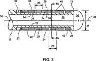
図2および3は、複数の相隔する切除素子24を有する細長本体12を示す。複数の相隔する切除素子24は、間隙26によって、隣接する切除素子24から互いに間隔をあけられている。切除素子24の間には、複数のトランスデューサ素子28が置かれる。一実施形態において、切除素子24およびトランスデューサ素子28は、交代式で本体12に作動可能に取り付けられる。装置2は、好ましくは、約2個と約14個との間の切除素子、および約3個と約15個との間のトランスデューサ素子を備える。より好ましくは、装置2は、切除素子24よりも少なくとも1つ多くのトランスデューサ素子28を有する。一実施形態において、温度センサ30は、遠位端10においてか遠位端10の近くに提供され、そして近位の温度センサ32は、切除素子24の近位に提供される。温度センサ30および温度センサ32は、好ましくは、熱電対を備える。温度センサ30および温度センサ32はまた、本発明の範囲内において、サーミスタなどを備え得る。温度センサまたは熱電対30および温度センサまたは熱電対32は、切除領域における温度を検出するように作動する。複数の絶縁体40は、トランスデューサ素子28と切除素子24との間に提供される。絶縁体40は、ポリイミド、ポリエステル、テフロン(登録商標)などを含み、トランスデューサ素子28を切除素子24から絶縁する。 2 and 3 show the
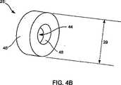
一実施形態において、トランスデューサ素子28は、図4A〜図4Bに最もよく示されるように、円筒形トランスデューサ素子を備える。トランスデューサ素子28は、外面46および内面48を備える。トランスデューサ素子28の内面48は、本体12の長軸方向軸38が各トランスデューサ素子28のスルーホール44を通り抜けるように、配置される。このような様式において、トランスデューサ素子28は、外面46が患者内の周辺の組織および流体に曝されるように構成される。この様式において、トランスデューサ素子28は、本体12またはトランスデューサ28を回転する必要なく長軸方向軸38にほぼ垂直な360°平面内を画像化するように作動し得る。本発明に範囲内において、他のトランスデューサ形状が使用され得ることが、当業者によって理解される。例えば、トランスデューサ素子28は、遠位端10に作動可能に取り付けられた長方形または楕円形のトランスデューサ素子を包含し得る。 In one embodiment,
トランスデューサ素子28は、超音波トランスデューサを含み得る。この実施形態において、トランスデューサ素子28は、ピエゾ複合材料、ピエゾセラミックス(例えば、PZT)、ピエゾプラスチックなどを含み得る。あるいは、以下で詳述されるように、トランスデューサ素子28は、磁界と電圧との間で変換するように適合され得る。他のトランスデューサ型(電気式、磁気式、電磁式、永久磁石式、ワイヤレス式、光学式などが挙げられるが、これらに限定されない)も、本発明の範囲内においてまた使用され得る。 The
図3に示されるような実施形態において、トランスデューサ28は、超音波 トランスデューサ素子28を含む。トランスデューサ28の各々は、各トランスデューサ素子28の外面46に作動可能に取り付けられた、整合層42または多層整合層42を備え得る。整合層42は、トランスデューサ素子28の性能を改善するように作動する。トランスデューサ素子28はまた、本発明の範囲内において、整合層42なしで作動し得る。 In the embodiment as shown in FIG. 3, the
トランスデューサ素子28は、外径29を有する。外径29は、可撓性細長本体12の外径31より小さいか、あるいは、直径31とほぼ等しい。好ましくは、本体12の直径31は、約8フレンチ未満であり、装置2の、患者の蛇行する脈管構造への導入を可能にする。 The
間隙26は、隣接する切除素子24を分離する。間隙26は、好ましくは、幅約1.5mmと約3.0mmとの間である。しかし間隙26は、より大きいサイズであってもより小さいサイズであってもよく、そして各2つの隣接する切除素子24の間で均一なサイズである必要はない。同様に、本発明の範囲内において、各間隙26は、トランスデューサ素子28を含む必要はなく、そして間隙26は、一以上のトランスデューサ素子28を含み得る。しかし、好ましくは、少なくともいくつかの間隙26はトランスデューサ素子28を含み、そしていくつかの実施形態において、切除素子24の間の各間隙26は、少なくとも一つのトランスデューサ素子28を含む。 A
細長本体12は、好ましくは、作業管腔39を備える。これを通って長軸方向軸38が通る。図4Aに最もよく示されるように、整合層42は、トランスデューサ素子28の外部表面の周辺に拡がる。整合層42は、トランスデューサ素子28に、好ましくはエポキシなどを用いて作動可能に取り付けられる。トランスデューサ素子28は、エポキシを含む種々の様式で、細長本体12に作動可能に取り付けられ得る。管腔39の使用は、図5Aおよび図5Bに最もよく示される。これらの図は、本発明の装置2の2つの代替的実施形態を示す。 The
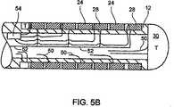
図5Aは、整合層42のない、図3に示される医療用カテーテル装置を示す。図5Aに最もよく示されるように、複数のリード線50が、熱電対30および32、トランスデューサ素子28、ならびに切除素子24に作動可能に取り付けられる。切除素子24のための電極を有する実施形態に関して、各電極は、単一のリード線50を有する。熱電対30および32は、各々一対のリード線50を有する。トランスデューサ素子28は、外面46と電気的に連絡する一本のリード線50を有する。さらに、接地52は、トランスデューサ28の内面48から延びる。図5Aに示されるように、特定の装置2の内部で、共通の接地が全てのトランスデューサ素子28のために使用され得る。共通の接地52を使用することの一つの利点は、より少ないリード線またはワイヤ50が遠位端10から管腔39を通ってコントローラ23へと通過することである。 FIG. 5A shows the medical catheter device shown in FIG. 3 without the
図5Bに示される実施形態は、可撓性細長本体12の遠位端10に作動可能に取り付けられたマルチプレクサー54の使用を示す。マルチプレクサー54は、好ましくは、切除素子24およびトランスデューサ素子28の近位に配置される。マルチプレクサー54は、リード線50をコントローラ23に通す必要なしに、トランスデューサ素子28からマルチプレクサー54へのこれらのリード線50の取り付けを可能にする。このような構造は、管腔39を通ってコントローラ23へと延ばす必要のあるワイヤの数を減少し得る。 The embodiment shown in FIG. 5B illustrates the use of a
マルチプレクサー54の操作は、図6と合わせて最もよく説明される。図6は、接地52およびリード線50を各々有するトランスデューサ素子28を示す。リード線50は、マルチプレクサー54に、好ましくはマルチプレクサー54の遠位側に、作動可能に取り付けられる。マルチプレクサー54は、接地62およびマルチプレクサー回路54に電力を提供するための伝達線60を有する。伝達および受信線56は、マルチプレクサー54に電気信号を伝達するための手段を提供する。次いで、マルチプレクサー54は、電気信号を適切なトランスデューサ28に方向付ける。伝達/受信ワイヤ56は、コントローラ23からマルチプレクサー54への直列な形式で、差次的なパルスとしてトランスデューサ28励起信号を運ぶ。マルチプレクサー54において、各励起信号は、コントローラ23によって使用される励起シーケンスを実行するために、トランスデューサ素子28のうちの適切なものへと経路を決められる。同様に、トランスデューサ素子28によって受信される帰路入力またはエコーは、マルチプレクサー54に伝達され、そして伝達/受信線56に沿ってコントローラ23に戻る。 The operation of
コントローラ23からトランスデューサ素子28の各々へと励起信号を運ぶために必要とされるワイヤの数を最小化することによって、細長本体12の直径、およびより具体的には管腔39のサイズは、減少され得る。あるいは、またはさらに、トランスデューサ素子28の数は、ワイヤが管腔39を通ってコントローラ23へと延ばされる必要なしに、遠位端10において増加され得る
マルチプレクサー54は、コントローラ23からマルチプレクサー54へと延びるクロック線58をさらに備え得る。クロック線58は、どのトランスデューサ素子28が励起信号を受信すべきかを決定することにおいて、マルチプレクサー54を補助する。あるいは、図6に示されるように、クロック線58は、伝達/受信線56を通って伝達される励起信号の数を計数することによって、およびマルチプレクサー54におけるカウンタを増加して、適切なトランスデューサ28への励起信号の伝達を調整することによって、作動する。一実施形態において、マルチプレクサー54はまた、コントローラ23からマルチプレクサー54へと延びるデータ線(図6に示されない)を備える。このデータ線は、コントローラ23がマルチプレクサー54の作動を制御することを可能にする。By minimizing the number of wires required to carry the excitation signal from the
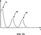
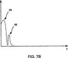
ここで図7および図8を見ると、本発明の一実施形態に従う医療用カテーテル装置2およびシステム4の作動が記載されている。医療用カテーテル装置2は、トランスデューサ素子28に細長本体12の遠位端10に対する組織70の近位性を検出させることによって作動する。コントローラ23は、トランスデューサ素子28の励起と周辺組織70からの反響信号66の受信との間の時間遅れを計算し、以下でさらに記載されるように、トランスデューサ素子28と組織70との間の距離を決定する。 Turning now to FIGS. 7 and 8, the operation of the
図7Aおよび図7Bに示されるように、励起信号64は、トランスデューサ素子28への伝達のため、コントローラ23からトランスデューサ素子28へ、またはマルチプレクサー54へ伝達される。励起信号64は、トランスデューサ28によって超音波信号へと変換される。この超音波信号は、患者内で、周辺の流体および組織内へと伝搬する。トランスデューサ素子28は、反響信号66を検出し、処理のため、これらの信号の電気的提示をコントローラ23に伝達する。 As shown in FIGS. 7A and 7B, the
コントローラ23は、励起64と反響信号66の受信との間の時間遅れを使用して、反響対象までのおおよその距離を計算する。コントローラ23は、図7に示されるように、低振幅の血液の反響とより大きな振幅の組織の反響66とを区別し得る。コントローラ23はさらに、ランダム化された後方散乱 対 より安定な組織散乱、から区別する。各トランスデューサ28から組織70への距離は、音速を知ることおよびより大きな振幅の組織反響への時間応答を測定することによって、計算され得る。信号が完全に、より大きな振幅の波形からなる場合、密接な接触が診断される。トランスデューサ28が、信号が測定され得ない不感の帯域/時間期間を実質的に有する場合、得られた不感帯域距離は、かなり小さい。例えば、30Mhzのトランスデューサに対して、この距離はおよそ0.15mmである。したがって、励起64が起こったほとんど直後に測定された反響信号66は、トランスデューサ28から組織70までの距離が約0.15mmの不感距離よりも小さいという結果となる。 The
したがって医療用カテーテルシステム4は、装置2を患者内に挿入すること、および装置2の遠位端10を患者の解剖学的構造の所望の位置近くに位置決めすることによって作動され得る。トランスデューサ素子28は、励起信号64によってエネルギー付加されて、反響信号66が受信され、そしてコントローラ23によって処理される。コントローラ23は、トランスデューサ素子28が組織70に接触しているか否かを決定する。少なくとも一つのトランスデューサ素子28が組織70と接触している場合、隣接する切除素子24を用いて、切除が起こり得る。好ましくは、図8に示されるように、組織70に接触する一以上のトランスデューサ素子28を有することが、望ましい。 Thus, the
コントローラ23は、種々の方法で作動して、組織70に接触している可能性のあるトランスデューサ素子28の数および配置を決定し得る。例えば、図8に示されるように、トランスデューサ素子28A、28Bおよび28Cは、それらが組織70に接触していることを示す。これは、医師が電極24Aおよび電極24Bを用いて組織70を切除することを可能にし得る。トランスデューサ素子28Dは、組織70と接触していることを示さない。したがって、切除素子24Cが組織70に接触しているか否かは決定的ではない。したがって、医師は、切除素子24Cで切除することを選択しない可能性がある。 The
一実施形態において、コントローラ23は、トランスデューサ素子28が組織70に接触している場合を示すため、緑色光および赤色光システムを使用し得る。特定の一実施形態において、例えば、コントローラ23は、図8に示される各トランスデューサ素子28A〜28Dのために、赤色光および緑色光を有する。緑色光は、対応するトランスデューサ素子28が組織70と接触している場合にコントローラ23によって照らされる。赤色光は、組織と接触していないこれらのトランスデューサ素子28のために照らされる。 In one embodiment, the
あるいは、単一の緑色光および赤色光が、装置2のために使用され得る。これによって、緑色光は、全てのトランスデューサ素子28が組織と接触している場合にのみコントローラ23によって照らされる。さらに別の実施形態は、単一の緑色光/赤色光のセットに対応するいくつかのトランスデューサ素子28を備える。例えば、素子28Aおよび28Bは、一つの緑色光を有し得、コントローラ23は、素子28Aと素子28Bとの両方が組織と接触している場合にこの光を照らす。素子28Aおよび素子28Bに対応する赤色光は、トランスデューサ素子28Aおよび28Bの一方もしくは両方が組織70と接触していない場合に照らされる。本発明の範囲内において、コントローラ23についての、組織70の接触がトランスデューサ素子28によって達成される場合を示す多くの方法(可聴のトーンなどを含む)が存在することが、当業者によって理解される。 Alternatively, a single green light and red light can be used for the
切除素子24は、好ましくは、単極切除のために使用されるが、双極切除もまた本発明の範囲内であることが理解される。切除素子24は、好ましくは電極を備える。この様式において、RF切除は、切除素子24を用いて生じ得る。 The
あるいは、切除素子24は、切除用超音波トランスデューサを備え得る。この様式において、トランスデューサ素子28は、パルスモードで操作されて、組織70からのそれらの距離を決定する。組織接触の際、切除トランスデューサ24は、組織70を切除するために使用される。音響切除のためのトランスデューサの使用は、米国特許第5,630、837号にさらに記載される。米国特許第5,630、837号の完全な開示は、既に、本明細書において参考として援用されている。 Alternatively, the
あるいは、トランスデューサ素子28は、組織70を画像化および切除するための両方に使用され得る。トランスデューサ素子28は、最初にパルスモードで操作され、トランスデューサ素子28が組織70と接触しているか否かを決定する。次いで、トランスデューサ素子28は、連続的波形を受信するか、約10〜15MHzの周波数を有する連続的波形電気信号をゲーティングし、そしてトランスデューサ素子28は、超音波切除を用いて組織70を切除する。 Alternatively,
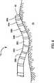
ここで、図9および図10を見ると、本発明に従う医療用カテーテル100および医療用カテーテルシステム200の代替的実施形態が、記載されている。医療用カテーテル100は、近位端110および遠位端120を有する細長本体105を備える。図10に示すように、近位端110は、操縦デバイス210に接続される。操縦デバイス210は、図1に関して記載されたものと類似していてもよいが、類似している必要はない。カテーテル100の長さは、本発明の範囲内において変動し得る。一実施形態において、カテーテル100の長さは、患者の脚の大腿静脈内への挿入を可能とし、かつ患者の脈管構造を通り抜けて心筋もしくは他の処置されるべき領域に達するのに十分な長さである。遠位端120は、図9に最もよく示されるように、それに接続されるかまたは他にその上に配置される、組織マッピング、組織配向検出、組織画像化、組織処置などのための、複数の素子を備える。図9に示される実施形態において、遠位端120は、カテーテル100の遠位先端か、またはその近くに配置された先端電極130を備える。一実施形態において、先端電極130は、以前に記載されたように、切除処置のための例示的電極を提供する。 Turning now to FIGS. 9 and 10, an alternative embodiment of a
カテーテル100は、遠位端120に接続された複数の相隔する電極132,134、および136を備える。一実施形態において、電極132〜136は、環状電極を備える。特定の実施形態において、環状電極134および136は、組織マッピング機能のための電極対として作動する。さらに、電極130および132が、組織マッピング機能のための電極対として作動し得る。カテーテル100は、細長本体105に沿って間隔をおいた複数の組織配向検出器140,142、144、および146をさらに備える。図9に示されるように、組織配向検出器140は、細長本体105の遠位先端近くに配置され、したがって、検出器140は、先端電極130に対して近接する。同様に、検出器146は、遠位端120の残りの素子に近接して配置され、遠位端120の位置を配向するためか、または遠位端120の位置を検出するために使用され得る。
遠位端120は、複数の絶縁体150をさらに備える。絶縁体150は、電極130〜136を互いに絶縁するように、および/または検出器140〜146を互いに絶縁するように、および/または電極130〜136から検出器140〜146を絶縁するように適合される。特定の実施形態において、各電極130〜136は、その隣に配置された、少なくとも一つの検出器140〜146を有し、それらの間には、おそらく、絶縁体150が介在する。例えば、先端電極130は、それらの近位に位置する検出器140を有する。電極132は、それらの遠位に位置する検出器140、およびそれらの近位に位置する検出器142を有する。電極134および136が、絶縁体150によってのみ互いに分離される場合、各電極134および136は、隣接する検出器142および144をそれぞれ有する。この様式において、検出器140〜146および電極130〜136は、本明細書においてさらに記載されるように、種々の手順のために、合わせて使用され得る。種々の検出器140〜146、電極130〜136および絶縁体150の配向および順番が本発明の範囲内において変化し得ることは、当業者によって理解される。 The
一実施形態において、組織配向検出器140〜146は、トランスデューサを備える。トランスデューサ140〜146は、種々の物理的パラメータの間を変換するように適合され得る。例えば、一実施形態において、トランスデューサ140〜146の少なくともいくつかは、超音波エネルギーと電圧との間を変換するように適合される。これは、例えば、一以上の検出器140〜146が、検出器140〜146の対向する表面にわたって電圧が印加された場合に超音波エネルギー波を伝達するように適合された、超音波トランスデューサを備える場合に起こり得る。超音波は、組織170に向かって伝わり、組織170によって反射される。反射された波は、検出器140〜146によって受信され、検出器140〜146によって電圧へと変換される。電圧は、図10に示されるように、コントローラ230へと伝達される。この様式において、検出器140〜146は、超音波エネルギーと電圧との間を変換する。あるいは、検出器140〜146は、電圧と磁界との間を変換するように適合され得る。例えば、磁場発生器もしくは電磁場発生器は、患者の近位に配置され得る。一実施形態において、カテーテルは、磁場もしくは電磁場を検出してそれを電圧に変換する、一以上のトランスデューサを保有する。次いで、電圧は、配向検出の目的のため、コントローラ230に供給される。あるいは、他のトランスデューサ型(電気トランスデューサ、永久磁石、光学トランスデューサなどが挙げられる)が使用され得る。 In one embodiment, the tissue orientation detectors 140-146 comprise transducers. Transducers 140-146 may be adapted to convert between various physical parameters. For example, in one embodiment, at least some of the transducers 140-146 are adapted to convert between ultrasonic energy and voltage. This includes, for example, an ultrasonic transducer in which one or more detectors 140-146 are adapted to transmit ultrasonic energy waves when a voltage is applied across the opposing surfaces of the detectors 140-146. Can happen. The ultrasonic waves travel toward the
医療用カテーテル100は、一以上の機能を行うように適合され、そして組織を画像化するように、組織をマッピングするように、組織に対するそれ自身の配向を補助するように、組織を処置するように、などに適合され得る。例えば、カテーテル100は、患者組織(例えば、心臓組織)をマッピングするために適合され得る。これは、本発明の範囲内における多くの方法で生じ得る。例えば、組織配向検出器140〜146は、カテーテル100を患者の脈管構造中に挿入して遠位端120を患者の所望の領域に移動することによって、使用され得る。次いで、カテーテル100は、一以上の基準カテーテルとともに使用されて、3次元配置プロセスを行い、患者の組織(例えば、心筋)の大まかな形状をマッピングするのを助け得る。3次元配置プロセスの詳細は、米国特許第6,490、474号(発明の名称「System and Method for Electrode Localization Using Ultrasound」)にさらに記載される。この特許の完全な開示は、あらゆる目的のため、本明細書において参考として援用される。 The
代替的実施形態において、カテーテル100は、組織170の電気活動をマッピングするために使用される。例えば一実施形態において、カテーテル100は、患者の所望の領域に挿入されて、一以上の電極130〜136が組織170と接触しているように配置される。次いで、心筋の電気活動をマッピングするために組織マッピング手順が行われ得る。このような電極マッピング技術は、以下にさらに記載される:米国特許第5,598,848号(発明の名称「Systems and Methods for Positioning Multiple Electrode Structures in Electrical Contact with the Myocardium」);米国特許第5,487,391号(発明の名称「Systems and Methods for Deriving and Displaying the Propagation Velocities of Electrical Events in the Heart」);および、米国特許第6,516,807号(発明の名称「System and Methods for Locating and Guiding Operative Elements within Interior Body Regions」)、これらの完全な開示は、あらゆる目的のため、本明細書において参考として援用される。 In an alternative embodiment, the
上記の参考文献は、マッピングされるべき心臓組織に接触して電極を配置するためのバスケット型カテーテル(basket catheter)の使用について考察しているが、本発明は、マッピングの前に組織接触を保証するように適合され得る。例えば、図1〜図8に関連して考察される技術が使用され得る。この技術としては、組織接触を確認するための、検出器140〜146によって伝達され、後に検出器140〜146によって受信される超音波信号の時間遅れが挙げられる。 Although the above references discuss the use of a basket catheter to place electrodes in contact with the heart tissue to be mapped, the present invention ensures tissue contact prior to mapping. Can be adapted to. For example, the techniques discussed in connection with FIGS. 1-8 may be used. This technique includes the time delay of ultrasound signals transmitted by detectors 140-146 and subsequently received by detectors 140-146 to confirm tissue contact.
代替的実施形態において、カテーテル100は、非接触式マッピング技術を用いて、組織170の電気活動をマッピングする。非接触式マッピングは、電極130〜136と組織170との間の間隙160が存在し得るという事実にもかかわらず、電極130〜136を使用して組織170内の電気活動を感知する。電極130〜136によって受信されるこれらの遠距離信号は、遠位端120と組織170との間の関係および組織170に対するカテーテル100の全体的配向を考慮したアルゴリズムを用いて、組織170の表面上でマッピングされる。この様式において、電気的に活性な組織170がマッピングされる。組織マッピング(非接触式マッピングを含む)におけるさらなる詳細は、米国特許第6,240,307号(発明の名称「Endocardial Mapping System」)において見出され得る。この特許の完全な開示は、本明細書において参考として援用される。 In an alternative embodiment, the
検出器140〜146、および/もしくは電極130〜136によって受信されるか、または発生したデータは、必要に応じて、ケ−ブル220または他の導電性の媒体を用いてカテーテル100をコントローラ230に接続することによって、コントローラ230に伝達され得る。一実施形態において、コントローラ230は、種々の手順を行うために適合されたソフトウェアもしくは他のプログラムを有するコンピュータが読み取り可能な保存媒体に接続された、マイクロプロセッサを備える。コントローラ230は、基準データ、アルゴリズムもしくは関連する処理ソフトウェアなどを含むコンパクトディスク、DVDなどを受容するための、入力デバイス250を備え得る。特定の実施形態において、コントローラ230は、一以上の検出器140〜146が組織170と接触している場合に操作者および医師に視覚的に表示するように適合された、光アレイ240をさらに備える。先に示したように、光アレイ240は、緑色/赤色システムを備え得、および/または視覚的インジケータもしくは音響式インジケータを備え得る。一実施形態において、コントローラ230は、カテーテル100から受信されたデータをデジタル化して組織170の画像をモニタ270上に表示するように適合された、デジタイザを備える。コントローラ230は、ケーブル260などを用いてモニタ270に接続され得る。あるいは、ワイヤレス接続が使用されて、コントローラ230をディスプレイ270に接続し得、および/またはコントローラ230をカテーテル100に接続し得る。 Data received or generated by the detectors 140-146 and / or electrodes 130-136 may be used to connect the
ここで図11を見ると、本発明に従う、カテーテル100を正確に配置するための方法300の実施形態が記載される。方法300は、カテーテル100を患者内に挿入する工程(ブロック310)を包含する。先に記載されるように、これは、例えば、カテーテル100を患者の大体静脈を通して挿入することによって起こり得る。次いで、カテーテル100は、組織をマッピングするために使用される(ブロック320)。この組織170のマッピングは、3次元配置技術および/または組織170内の電気的活動のマッピング(いずれも先に記載される)を包含する。方法300は、処置されるべき組織領域を同定する工程をさらに包含する(ブロック330)。これは、例えば、医師または他のシステム200の操作者による精査のため、ディスプレイ270上に組織170の画像を表示することによって起こり得る。 Turning now to FIG. 11, an embodiment of a
方法300は、細長本体105の位置決めの工程をさらに包含する(ブロック340)。これは、先に記載されたような種々の手順に関与し得、そして患者の所望の領域内にカテーテル100を配向するための検出器140〜146の使用を包含する。例えば、検出器140〜146は、遠位端120が患者の適切な領域内にあることを概ね決定するために、使用され得る。さらに、カテーテル100の位置決めは、一以上の検出器140〜146を用いて接触されている組織170を決定する工程を包含し得る。別の実施形態において、電極130〜136は、カテーテル100の配向を容易にするために使用される。これは、例えば、心臓からの電気信号を受信して、その電気信号を以前に作製された組織170の電気信号のマップ(例えば、ブロック320における組織マッピングの結果として受け取ったマップ)と比較することによって起こり得る。この比較は、組織170に対するカテーテル100の配向の決定を補助し得る。 The
一旦カテーテル100が正確に位置決めされた場合、または非接触技術が利用される場合は心臓マップが一旦得られた場合、医師もしくはシステム200のオペレータは、必要に応じて組織170を処置し得る(ブロック350)。先に考察されるように、このような処置の一つは、(例えば、心房細動を処置するために所望され得る)組織170もしくは組織170の一部分の切除に関する。方法300の処置局面は、切除の代わりに、組織170に対する医薬の送達または他の治療をさらに包含し得る。方法300が、一連のプロセスを包含するものとして描かれ記載される一方で、図11に同定された手順が、示された順序とは異なる順序で起こり得るということが、当業者によって理解される。例えば、医師は、処置されるべき組織領域を既に同定していてもよい。この場合、ブロック330は、方法300から除去され得る。さらに、ブロック340における細長本体の位置決めは、組織マッピングの前、および/または組織処置の後に起こり得る
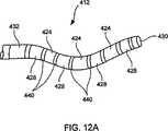
本発明に従う医療用カテーテルの代替的実施形態は、図12Aおよび図12Bに関連して記載される。示されるように、カテーテルは、作業管腔439および長軸方向軸438を有する細長本体412を備える。複数の相隔する電極424は、本体412上に配置される。電極424の間に置かれるのは、複数の組織配向検出器428である。一実施形態において、組織配向検出器428は、トランスデューサ素子428を備える。配向検出器428がトランスデューサ、特に超音波トランスデューサを備える実施形態について、検出器428は、検出器428の少なくともいくつかの外面446に作動可能に取り付けられた、一以上の整合層442を備え得る。整合層442は、トランスデューサ428の性能を改善するように作動する。本発明の範囲内において、検出器428はまた、整合層442なしで作動し得る。さらに、別の様式で細長本体412に接続されて示されるが、電極424および検出器428の並べ方は、本発明の範囲内において変化し得る。Once the
検出器428は、可撓性細長本体412の外径431未満であり得るか、あるいは直径431にほぼ同じであり得る外径を有する。好ましくは、本体412の直径431は、約8フレンチ未満であって、患者の蛇行する脈管構造への医療用カテーテルの導入を可能にする。複数の間隙426は、電極424および検出器428を互いに(each other)および/または互いに(one another)分離する。各間隙426は、検出器428を含む必要はなく、かつ間隙426は、本発明の範囲内において、一以上の検出器428を含み得る。複数の絶縁体440は、配向検出器428の少なくともいくつかおよび/または電極424の少なくともいくつかの間に配置される。絶縁体440は、ポリイミド、ポリエステル、テフロン(登録商標)などを含み、隣接する検出器428および/または電極424を絶縁し得る。 The
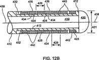
一実施形態において、温度センサ430は、本体412の遠位端か、またはその近くに配置され、そして近位温度センサ432は、電極424の近くに配置される。温度センサ430および432は、本発明の範囲内において、熱電対、サーミスタなどを備え得る。代替的実施形態において、温度センサ432は、先端電極と置き換えられる。この様式において、細長本体412の遠位先端は、マッピング手順および/または切除手順のために使用され得る。 In one embodiment, the
一実施形態において、電極424は、組織マッピング機能のために適合される。特定の実施形態において、電極424は、組織マッピング機能のみのために適合され、それに従って寸法を決められ得る。例えば、電極424は環状電極を備え得る。このような実施形態において、電極424は、類似の切除電極よりもより小さく露出された外部表面436を有し得る。特定の実施形態において、電極424は、さらに内部表面434を備え、これは、管腔439を通って延びる一本もしくは複数のワイヤ(示さず)を有することによって、コントローラに対する電気的接続を容易にする。この様式において、図12Aおよび図12Bのカテーテルは、組織マッピングおよび組織配向機能のために、そして必要に応じて組織切除のために適合される。組織画像化も、また包含され得る。 In one embodiment,
本発明は、ここに詳細に記載された。しかし、特定の変更および改変が行われ得ることが理解される。例えば、図2、図3、図5および図8は、切除素子24の全ての間に置かれたトランスデューサ素子28を示すが、トランスデューサ28は、切除素子24のいくつかの間および間隙26のいくつかに存在するのみであってよい。したがって、本発明の範囲および内容は、前述の記載によって限定されない。むしろ、本発明の範囲および内容は、以下の特許請求の範囲によって定義されるべきである。 The invention has been described in detail herein. However, it is understood that certain changes and modifications may be made. For example, FIGS. 2, 3, 5 and 8 show a
Claims (35)
Translated fromJapanese近位端および遠位端を有する可撓性細長本体;
遠位端近くで該可撓性本体に作動可能に取り付けられた、複数の相隔するマッピング電極であって、組織をマッピングするために適合されているマッピング電極;
該組織の所望の部分を切除するために適合されている少なくとも1つの切除電極;および、
複数の組織配向検出器であって、該複数の組織配向検出器は、該可撓性本体の外部表面に沿って間隔をおいて配設されており、該組織配向検出器は、該組織に対する該可撓性細長本体の配向を決定するために適合されており、該組織配向検出器のうちの少なくともいくつかが、該マッピング電極のうちの少なくともいくつかの間に配置されている、組織配向検出器、
を備える、医療用カテーテル。A medical catheter, the following:
A flexible elongate body having a proximal end and a distal end;
A plurality of spaced-apart mapping electrodes operatively attached to the flexible body near the distal end, the mapping electrodes being adapted for mapping tissue;
At least one ablation electrode adapted to ablate a desired portion of the tissue; and
A plurality of tissue orientation detectors, wherein the plurality of tissue orientation detectors are spaced along the outer surface of the flexible body, thetissue orientation detectors relative to the tissue; A tissue orientation detectoradapted to determine an orientation of the flexible elongate body, wherein at least some of the tissue orientation detectors are disposed between at least some of the mapping electrodes ,
A medical catheter comprising:
請求項1に記載の医療用カテーテル;および、
前記複数のマッピング電極に接続され、かつ前記複数の組織配向検出器に接続されたコントローラであって、該組織配向検出器の各々からの信号を用いて、該組織配向検出器の各々が組織と接触しているか否かを決定するように構成され、かつ配設されているコントローラ、
を備える、医療用カテーテルシステム。A medical catheter system comprising:
The medical catheter of claim 1; and
A controller connected to the plurality of mapping electrodes and connected to the plurality of tissue orientation detectors, each using the signal from each of the tissue orientation detectors, A controller configured and arranged to determine whether it is in contact;
A medical catheter system comprising:
請求項10に記載の医療用カテーテルシステム;
前記可撓性細長本体を患者に挿入するための手段;
前記複数のマッピング電極のうちの少なくともいくつかを用いて、該組織の電気的プロフィールをマッピングするための手段;および、
前記複数の組織配向検出器を用い、該組織の電気的プロフィールに部分的に基づいて、該細長本体を該組織に近接するように位置決めするための手段、
を備える、システム。A system for accurately positioning a medical catheter relative to tissue, the system comprising:
The medical catheter system according to claim 10;
Means for inserting said flexible elongate body into a patient;
Means for mapping the electrical profile of the tissue using at least some of the plurality of mapping electrodes; and
Means for positioning the elongate body proximate to the tissue using the plurality of tissue orientation detectors based in part on the electrical profile of the tissue;
A system comprising:
請求項1に記載の医療用カテーテルであって、前記複数の組織配向検出器が、複数のトランスデューサを備える、医療用カテーテル;
組織プロフィールを作製するために、前記複数の相隔するマッピング電極のうちの少なくともいくつかを用いて、該患者の組織をマッピングするための手段;
該組織プロフィールを用いて、処置されるべき組織領域を同定するための手段;および、
前記少なくとも1つの切除電極のうちの少なくとも一つが該組織領域に近接するように、該トランスデューサを用いて該細長本体を位置決めするための手段、
を備える、システム。A system for accurately positioning a catheter within a patient, the system comprising:
The medical catheter according to claim 1, wherein the plurality of tissue orientation detectors comprise a plurality of transducers;
Means for mapping the patient's tissue using at least some of the plurality of spaced mapping electrodes to create a tissue profile;
Means for identifying a tissue region to be treated using the tissue profile; and
Means for positioning the elongated body using the transducer such that at least one of the at least one ablation electrode is proximate to the tissue region;
A system comprising:
請求項1に記載のカテーテル;
組織プロフィールを作製するために、前記複数の相隔するマッピング電極のうちの少なくともいくつかを用いて、患者の組織をマッピングするための手段;
該組織プロフィールを用いて、処置されるべき組織を同定するための手段;
前記少なくとも1つの切除電極のうちの少なくとも一つが該処置されるべき組織に近接するように、前記組織配向検出器を用いて前記細長本体を位置決めするための手段;および、
該カテーテルを用いて該組織を処置するための手段、
を備える、システム。A system for diagnosing and treating cardiac rhythm disorders, the system comprising:
The catheter of claim 1;
Means for mapping a patient's tissue using at least some of the plurality of spaced apart mapping electrodes to create a tissue profile;
Means for identifying the tissue to be treated using the tissue profile;
Means for positioning the elongate body using the tissue orientation detector such that at least one of the at least one ablation electrode is proximate to the tissue to be treated; and
Means for treating the tissue with the catheter;
A system comprising:
Applications Claiming Priority (3)
| Application Number | Priority Date | Filing Date | Title |
|---|---|---|---|
| US10/428,308US7194294B2 (en) | 1999-01-06 | 2003-05-02 | Multi-functional medical catheter and methods of use |
| US10/428,308 | 2003-05-02 | ||
| PCT/US2004/005127WO2004098694A1 (en) | 2003-05-02 | 2004-02-20 | Multi-functional medical catheter |
Publications (2)
| Publication Number | Publication Date |
|---|---|
| JP2006525072A JP2006525072A (en) | 2006-11-09 |
| JP4850697B2true JP4850697B2 (en) | 2012-01-11 |
Family
ID=40935518
Family Applications (1)
| Application Number | Title | Priority Date | Filing Date |
|---|---|---|---|
| JP2006508785AExpired - Fee RelatedJP4850697B2 (en) | 2003-05-02 | 2004-02-20 | Multi-function medical catheter |
Country Status (4)
| Country | Link |
|---|---|
| EP (1) | EP1620156B1 (en) |
| JP (1) | JP4850697B2 (en) |
| CA (1) | CA2524163C (en) |
| WO (1) | WO2004098694A1 (en) |
Cited By (1)
| Publication number | Priority date | Publication date | Assignee | Title |
|---|---|---|---|---|
| US9999365B2 (en) | 2013-08-23 | 2018-06-19 | Korea University Research And Business Foundation | Mapping ablation catheter |
Families Citing this family (106)
| Publication number | Priority date | Publication date | Assignee | Title |
|---|---|---|---|---|
| US8241274B2 (en) | 2000-01-19 | 2012-08-14 | Medtronic, Inc. | Method for guiding a medical device |
| US7617005B2 (en) | 2002-04-08 | 2009-11-10 | Ardian, Inc. | Methods and apparatus for thermally-induced renal neuromodulation |
| US8150519B2 (en) | 2002-04-08 | 2012-04-03 | Ardian, Inc. | Methods and apparatus for bilateral renal neuromodulation |
| DE202004021953U1 (en) | 2003-09-12 | 2013-06-19 | Vessix Vascular, Inc. | Selectable eccentric remodeling and / or ablation of atherosclerotic material |
| US8396548B2 (en) | 2008-11-14 | 2013-03-12 | Vessix Vascular, Inc. | Selective drug delivery in a lumen |
| US9713730B2 (en) | 2004-09-10 | 2017-07-25 | Boston Scientific Scimed, Inc. | Apparatus and method for treatment of in-stent restenosis |
| EP2438877B1 (en) | 2005-03-28 | 2016-02-17 | Vessix Vascular, Inc. | Intraluminal electrical tissue characterization and tuned RF energy for selective treatment of atheroma and other target tissues |
| US8672936B2 (en) | 2005-10-13 | 2014-03-18 | St. Jude Medical, Atrial Fibrillation Division, Inc. | Systems and methods for assessing tissue contact |
| BRPI0618421A2 (en) | 2005-10-27 | 2011-08-30 | St Jude Medical Atrial Fibrill | systems and methods for electrode contact evaluation |
| US8382674B2 (en)* | 2005-12-02 | 2013-02-26 | Abbott Cardiovascular Systems Inc. | Visualization of a catheter viewed under ultrasound imaging |
| US8019435B2 (en) | 2006-05-02 | 2011-09-13 | Boston Scientific Scimed, Inc. | Control of arterial smooth muscle tone |
| US20080039746A1 (en) | 2006-05-25 | 2008-02-14 | Medtronic, Inc. | Methods of using high intensity focused ultrasound to form an ablated tissue area containing a plurality of lesions |
| EP2455036B1 (en) | 2006-10-18 | 2015-07-15 | Vessix Vascular, Inc. | Tuned RF energy and electrical tissue characterization for selective treatment of target tissues |
| EP2076198A4 (en) | 2006-10-18 | 2009-12-09 | Minnow Medical Inc | Inducing desirable temperature effects on body tissue |
| JP5559539B2 (en) | 2006-10-18 | 2014-07-23 | べシックス・バスキュラー・インコーポレイテッド | System that induces desirable temperature effects on body tissue |
| US10085798B2 (en) | 2006-12-29 | 2018-10-02 | St. Jude Medical, Atrial Fibrillation Division, Inc. | Ablation electrode with tactile sensor |
| US8226648B2 (en) | 2007-12-31 | 2012-07-24 | St. Jude Medical, Atrial Fibrillation Division, Inc. | Pressure-sensitive flexible polymer bipolar electrode |
| US8496653B2 (en) | 2007-04-23 | 2013-07-30 | Boston Scientific Scimed, Inc. | Thrombus removal |
| WO2009117523A2 (en)* | 2008-03-18 | 2009-09-24 | Circa Medical, Llc | Large surface area temperature sensing device |
| EP2355737B1 (en) | 2008-11-17 | 2021-08-11 | Boston Scientific Scimed, Inc. | Selective accumulation of energy without knowledge of tissue topography |
| US8551096B2 (en) | 2009-05-13 | 2013-10-08 | Boston Scientific Scimed, Inc. | Directional delivery of energy and bioactives |
| US8706193B2 (en)* | 2009-06-22 | 2014-04-22 | Biosense Webster, Inc. | Catheter with obliquely-oriented coils |
| US9907534B2 (en)* | 2009-12-15 | 2018-03-06 | St. Jude Medical, Atrial Fibrillation Division, Inc. | Self-aiming directable acoustic transducer assembly for invasive medical device applications |
| WO2011126580A2 (en) | 2010-04-09 | 2011-10-13 | Minnow Medical, Inc. | Power generating and control apparatus for the treatment of tissue |
| US9192790B2 (en) | 2010-04-14 | 2015-11-24 | Boston Scientific Scimed, Inc. | Focused ultrasonic renal denervation |
| US8473067B2 (en) | 2010-06-11 | 2013-06-25 | Boston Scientific Scimed, Inc. | Renal denervation and stimulation employing wireless vascular energy transfer arrangement |
| US20110313280A1 (en)* | 2010-06-16 | 2011-12-22 | Assaf Govari | Optical contact sensing in medical probes |
| US11490957B2 (en) | 2010-06-16 | 2022-11-08 | Biosense Webster (Israel) Ltd. | Spectral sensing of ablation |
| US10314650B2 (en) | 2010-06-16 | 2019-06-11 | Biosense Webster (Israel) Ltd. | Spectral sensing of ablation |
| US9408661B2 (en) | 2010-07-30 | 2016-08-09 | Patrick A. Haverkost | RF electrodes on multiple flexible wires for renal nerve ablation |
| US9358365B2 (en) | 2010-07-30 | 2016-06-07 | Boston Scientific Scimed, Inc. | Precision electrode movement control for renal nerve ablation |
| US9463062B2 (en) | 2010-07-30 | 2016-10-11 | Boston Scientific Scimed, Inc. | Cooled conductive balloon RF catheter for renal nerve ablation |
| US9155589B2 (en) | 2010-07-30 | 2015-10-13 | Boston Scientific Scimed, Inc. | Sequential activation RF electrode set for renal nerve ablation |
| US9084609B2 (en) | 2010-07-30 | 2015-07-21 | Boston Scientific Scime, Inc. | Spiral balloon catheter for renal nerve ablation |
| US8974451B2 (en) | 2010-10-25 | 2015-03-10 | Boston Scientific Scimed, Inc. | Renal nerve ablation using conductive fluid jet and RF energy |
| US9220558B2 (en) | 2010-10-27 | 2015-12-29 | Boston Scientific Scimed, Inc. | RF renal denervation catheter with multiple independent electrodes |
| US9028485B2 (en) | 2010-11-15 | 2015-05-12 | Boston Scientific Scimed, Inc. | Self-expanding cooling electrode for renal nerve ablation |
| US9089350B2 (en) | 2010-11-16 | 2015-07-28 | Boston Scientific Scimed, Inc. | Renal denervation catheter with RF electrode and integral contrast dye injection arrangement |
| US9668811B2 (en) | 2010-11-16 | 2017-06-06 | Boston Scientific Scimed, Inc. | Minimally invasive access for renal nerve ablation |
| US9326751B2 (en) | 2010-11-17 | 2016-05-03 | Boston Scientific Scimed, Inc. | Catheter guidance of external energy for renal denervation |
| US9060761B2 (en) | 2010-11-18 | 2015-06-23 | Boston Scientific Scime, Inc. | Catheter-focused magnetic field induced renal nerve ablation |
| US9192435B2 (en) | 2010-11-22 | 2015-11-24 | Boston Scientific Scimed, Inc. | Renal denervation catheter with cooled RF electrode |
| US9023034B2 (en) | 2010-11-22 | 2015-05-05 | Boston Scientific Scimed, Inc. | Renal ablation electrode with force-activatable conduction apparatus |
| US20120157993A1 (en) | 2010-12-15 | 2012-06-21 | Jenson Mark L | Bipolar Off-Wall Electrode Device for Renal Nerve Ablation |
| US9220561B2 (en) | 2011-01-19 | 2015-12-29 | Boston Scientific Scimed, Inc. | Guide-compatible large-electrode catheter for renal nerve ablation with reduced arterial injury |
| JP5432932B2 (en)* | 2011-01-31 | 2014-03-05 | 平河ヒューテック株式会社 | Electrode catheter |
| US9757044B2 (en) | 2011-03-10 | 2017-09-12 | Acutus Medical, Inc. | Device and method for the geometric determination of electrical dipole densities on the cardiac wall |
| CN103813745B (en) | 2011-07-20 | 2016-06-29 | 波士顿科学西美德公司 | In order to visualize, be directed at and to melt transcutaneous device and the method for nerve |
| EP2734264B1 (en) | 2011-07-22 | 2018-11-21 | Boston Scientific Scimed, Inc. | Nerve modulation system with a nerve modulation element positionable in a helical guide |
| WO2013055826A1 (en) | 2011-10-10 | 2013-04-18 | Boston Scientific Scimed, Inc. | Medical devices including ablation electrodes |
| EP2765940B1 (en) | 2011-10-11 | 2015-08-26 | Boston Scientific Scimed, Inc. | Off-wall electrode device for nerve modulation |
| US9420955B2 (en) | 2011-10-11 | 2016-08-23 | Boston Scientific Scimed, Inc. | Intravascular temperature monitoring system and method |
| US9364284B2 (en) | 2011-10-12 | 2016-06-14 | Boston Scientific Scimed, Inc. | Method of making an off-wall spacer cage |
| US9162046B2 (en) | 2011-10-18 | 2015-10-20 | Boston Scientific Scimed, Inc. | Deflectable medical devices |
| EP2768568B1 (en) | 2011-10-18 | 2020-05-06 | Boston Scientific Scimed, Inc. | Integrated crossing balloon catheter |
| US8951251B2 (en) | 2011-11-08 | 2015-02-10 | Boston Scientific Scimed, Inc. | Ostial renal nerve ablation |
| WO2013074813A1 (en) | 2011-11-15 | 2013-05-23 | Boston Scientific Scimed, Inc. | Device and methods for renal nerve modulation monitoring |
| US9119632B2 (en) | 2011-11-21 | 2015-09-01 | Boston Scientific Scimed, Inc. | Deflectable renal nerve ablation catheter |
| US9265969B2 (en) | 2011-12-21 | 2016-02-23 | Cardiac Pacemakers, Inc. | Methods for modulating cell function |
| US9028472B2 (en) | 2011-12-23 | 2015-05-12 | Vessix Vascular, Inc. | Methods and apparatuses for remodeling tissue of or adjacent to a body passage |
| EP2797534A1 (en) | 2011-12-28 | 2014-11-05 | Boston Scientific Scimed, Inc. | Device and methods for nerve modulation using a novel ablation catheter with polymeric ablative elements |
| US9050106B2 (en) | 2011-12-29 | 2015-06-09 | Boston Scientific Scimed, Inc. | Off-wall electrode device and methods for nerve modulation |
| US10660703B2 (en) | 2012-05-08 | 2020-05-26 | Boston Scientific Scimed, Inc. | Renal nerve modulation devices |
| US10321946B2 (en) | 2012-08-24 | 2019-06-18 | Boston Scientific Scimed, Inc. | Renal nerve modulation devices with weeping RF ablation balloons |
| EP2890292B1 (en) | 2012-08-31 | 2021-01-13 | Acutus Medical, Inc. | Catheter system for the heart |
| CN104780859B (en) | 2012-09-17 | 2017-07-25 | 波士顿科学西美德公司 | Self-positioning electrode systems and methods for renal neuromodulation |
| US10549127B2 (en) | 2012-09-21 | 2020-02-04 | Boston Scientific Scimed, Inc. | Self-cooling ultrasound ablation catheter |
| US10398464B2 (en) | 2012-09-21 | 2019-09-03 | Boston Scientific Scimed, Inc. | System for nerve modulation and innocuous thermal gradient nerve block |
| CN104869930B (en) | 2012-10-10 | 2020-12-25 | 波士顿科学国际有限公司 | Renal neuromodulation apparatus and methods |
| CN105358070B (en)* | 2013-02-08 | 2018-03-23 | 阿库图森医疗有限公司 | Expandable catheter assembly with flexible printed circuit board |
| WO2014143571A1 (en) | 2013-03-11 | 2014-09-18 | Boston Scientific Scimed, Inc. | Medical devices for modulating nerves |
| WO2014163987A1 (en) | 2013-03-11 | 2014-10-09 | Boston Scientific Scimed, Inc. | Medical devices for modulating nerves |
| US9808311B2 (en) | 2013-03-13 | 2017-11-07 | Boston Scientific Scimed, Inc. | Deflectable medical devices |
| US10265122B2 (en) | 2013-03-15 | 2019-04-23 | Boston Scientific Scimed, Inc. | Nerve ablation devices and related methods of use |
| CN105228546B (en) | 2013-03-15 | 2017-11-14 | 波士顿科学国际有限公司 | Medical devices and methods for treating hypertension utilizing impedance compensation |
| EP2967734B1 (en) | 2013-03-15 | 2019-05-15 | Boston Scientific Scimed, Inc. | Methods and apparatuses for remodeling tissue of or adjacent to a body passage |
| CN105473092B (en) | 2013-06-21 | 2019-05-17 | 波士顿科学国际有限公司 | The medical instrument for renal nerve ablation with rotatable shaft |
| CN105473091B (en) | 2013-06-21 | 2020-01-21 | 波士顿科学国际有限公司 | Renal denervation balloon catheter with co-movable electrode supports |
| US9707036B2 (en) | 2013-06-25 | 2017-07-18 | Boston Scientific Scimed, Inc. | Devices and methods for nerve modulation using localized indifferent electrodes |
| CN105358084B (en) | 2013-07-01 | 2018-11-09 | 波士顿科学国际有限公司 | Medical instrument for renal nerve ablation |
| US10413357B2 (en) | 2013-07-11 | 2019-09-17 | Boston Scientific Scimed, Inc. | Medical device with stretchable electrode assemblies |
| CN105377169B (en) | 2013-07-11 | 2019-04-19 | 波士顿科学国际有限公司 | Devices and methods for neuromodulation |
| US9925001B2 (en) | 2013-07-19 | 2018-03-27 | Boston Scientific Scimed, Inc. | Spiral bipolar electrode renal denervation balloon |
| US10695124B2 (en) | 2013-07-22 | 2020-06-30 | Boston Scientific Scimed, Inc. | Renal nerve ablation catheter having twist balloon |
| US10342609B2 (en) | 2013-07-22 | 2019-07-09 | Boston Scientific Scimed, Inc. | Medical devices for renal nerve ablation |
| CN105473093B (en) | 2013-08-22 | 2019-02-05 | 波士顿科学国际有限公司 | Flexible circuit with improved adhesion to renal neuromodulation balloon |
| KR101459940B1 (en)* | 2013-08-23 | 2014-11-07 | 고려대학교 산학협력단 | Catheter for mapping and ablating lesion parts |
| US9895194B2 (en) | 2013-09-04 | 2018-02-20 | Boston Scientific Scimed, Inc. | Radio frequency (RF) balloon catheter having flushing and cooling capability |
| CA2922941C (en) | 2013-09-13 | 2021-11-16 | Acutus Medical, Inc. | Devices and methods for determination of electrical dipole densities on a cardiac surface |
| EP3057488B1 (en) | 2013-10-14 | 2018-05-16 | Boston Scientific Scimed, Inc. | High resolution cardiac mapping electrode array catheter |
| US11246654B2 (en) | 2013-10-14 | 2022-02-15 | Boston Scientific Scimed, Inc. | Flexible renal nerve ablation devices and related methods of use and manufacture |
| US9770606B2 (en) | 2013-10-15 | 2017-09-26 | Boston Scientific Scimed, Inc. | Ultrasound ablation catheter with cooling infusion and centering basket |
| US9962223B2 (en) | 2013-10-15 | 2018-05-08 | Boston Scientific Scimed, Inc. | Medical device balloon |
| EP3057521B1 (en) | 2013-10-18 | 2020-03-25 | Boston Scientific Scimed, Inc. | Balloon catheters with flexible conducting wires |
| CN105658163B (en) | 2013-10-25 | 2020-08-18 | 波士顿科学国际有限公司 | Embedded thermocouple in denervation flexible circuit |
| EP3091922B1 (en) | 2014-01-06 | 2018-10-17 | Boston Scientific Scimed, Inc. | Tear resistant flex circuit assembly |
| US11000679B2 (en) | 2014-02-04 | 2021-05-11 | Boston Scientific Scimed, Inc. | Balloon protection and rewrapping devices and related methods of use |
| CN106572881B (en) | 2014-02-04 | 2019-07-26 | 波士顿科学国际有限公司 | Alternative placement of thermal sensors on bipolar electrodes |
| JP6116505B2 (en)* | 2014-03-13 | 2017-04-19 | 日本ライフライン株式会社 | Electrode catheter with temperature sensor |
| JP6739346B2 (en) | 2014-03-25 | 2020-08-12 | アクタス メディカル インクAcutus Medical,Inc. | Method of operating system of cardiac analysis user interface |
| JP5969635B2 (en) | 2015-01-15 | 2016-08-17 | 日本ライフライン株式会社 | catheter |
| CN115299988A (en) | 2015-05-12 | 2022-11-08 | 阿库图森医疗有限公司 | Ultrasonic sequencing systems and methods |
| US10653318B2 (en) | 2015-05-13 | 2020-05-19 | Acutus Medical, Inc. | Localization system and method useful in the acquisition and analysis of cardiac information |
| US12178582B2 (en) | 2018-11-09 | 2024-12-31 | Acutus Medical, Inc. | Systems and methods for calculating patient information |
| CA3135773A1 (en) | 2019-06-04 | 2020-12-10 | Acutus Medical, Inc. | Systems and methods for performing localization within a body |
| WO2022153082A1 (en)* | 2021-01-14 | 2022-07-21 | Baylis Medical Company Inc | Medical dilator, and systems, methods, and kits for medical dilation |
Citations (6)
| Publication number | Priority date | Publication date | Assignee | Title |
|---|---|---|---|---|
| JPH07178113A (en)* | 1991-02-15 | 1995-07-18 | Cardiac Pathways Corp | Endocardium mapping/separating system, and catheter probe and its method |
| US5643197A (en)* | 1993-12-21 | 1997-07-01 | Angeion Corporation | Fluid cooled and perfused tip for a catheter |
| US5882346A (en)* | 1996-07-15 | 1999-03-16 | Cardiac Pathways Corporation | Shapable catheter using exchangeable core and method of use |
| EP0928601A1 (en)* | 1997-12-01 | 1999-07-14 | Cordis Webster, Inc. | Irrigated tip catheter |
| US6240307B1 (en)* | 1993-09-23 | 2001-05-29 | Endocardial Solutions, Inc. | Endocardial mapping system |
| US6490474B1 (en)* | 1997-08-01 | 2002-12-03 | Cardiac Pathways Corporation | System and method for electrode localization using ultrasound |
Family Cites Families (1)
| Publication number | Priority date | Publication date | Assignee | Title |
|---|---|---|---|---|
| US5630837A (en) | 1993-07-01 | 1997-05-20 | Boston Scientific Corporation | Acoustic ablation |
- 2004
- 2004-02-20EPEP04713393Apatent/EP1620156B1/ennot_activeExpired - Lifetime
- 2004-02-20CACA2524163Apatent/CA2524163C/ennot_activeExpired - Fee Related
- 2004-02-20JPJP2006508785Apatent/JP4850697B2/ennot_activeExpired - Fee Related
- 2004-02-20WOPCT/US2004/005127patent/WO2004098694A1/enactiveApplication Filing
Patent Citations (6)
| Publication number | Priority date | Publication date | Assignee | Title |
|---|---|---|---|---|
| JPH07178113A (en)* | 1991-02-15 | 1995-07-18 | Cardiac Pathways Corp | Endocardium mapping/separating system, and catheter probe and its method |
| US6240307B1 (en)* | 1993-09-23 | 2001-05-29 | Endocardial Solutions, Inc. | Endocardial mapping system |
| US5643197A (en)* | 1993-12-21 | 1997-07-01 | Angeion Corporation | Fluid cooled and perfused tip for a catheter |
| US5882346A (en)* | 1996-07-15 | 1999-03-16 | Cardiac Pathways Corporation | Shapable catheter using exchangeable core and method of use |
| US6490474B1 (en)* | 1997-08-01 | 2002-12-03 | Cardiac Pathways Corporation | System and method for electrode localization using ultrasound |
| EP0928601A1 (en)* | 1997-12-01 | 1999-07-14 | Cordis Webster, Inc. | Irrigated tip catheter |
Cited By (1)
| Publication number | Priority date | Publication date | Assignee | Title |
|---|---|---|---|---|
| US9999365B2 (en) | 2013-08-23 | 2018-06-19 | Korea University Research And Business Foundation | Mapping ablation catheter |
Also Published As
| Publication number | Publication date |
|---|---|
| WO2004098694A1 (en) | 2004-11-18 |
| CA2524163C (en) | 2012-01-03 |
| JP2006525072A (en) | 2006-11-09 |
| EP1620156B1 (en) | 2009-07-29 |
| CA2524163A1 (en) | 2004-11-18 |
| EP1620156A1 (en) | 2006-02-01 |
Similar Documents
| Publication | Publication Date | Title |
|---|---|---|
| JP4850697B2 (en) | Multi-function medical catheter | |
| US7364546B2 (en) | Multi-functional medical catheter and methods of use | |
| US6206831B1 (en) | Ultrasound-guided ablation catheter and methods of use | |
| JP6914648B2 (en) | Use of force sensors to give the angle of the ultrasonic beam | |
| JP5830614B2 (en) | Ablation probe with fluid-based acoustic coupling for ultrasound tissue imaging and ablation and ultrasound imaging system | |
| US6970733B2 (en) | System and method for electrode localization using ultrasound | |
| US20040147920A1 (en) | Prediction and assessment of ablation of cardiac tissue | |
| JP2014516723A (en) | Ablation probe with ultrasound imaging capability | |
| JP2015506209A (en) | Ablation probe and ablation and ultrasound imaging system | |
| JP3740550B2 (en) | Catheter device for evaluation of transvascular, ultrasound and hemodynamics | |
| US20140336477A1 (en) | Far-field and near-field ultrasound imaging device | |
| US20210401492A1 (en) | Systems and methods for assessing ablation lesions |
Legal Events
| Date | Code | Title | Description |
|---|---|---|---|
| A621 | Written request for application examination | Free format text:JAPANESE INTERMEDIATE CODE: A621 Effective date:20070215 | |
| A131 | Notification of reasons for refusal | Free format text:JAPANESE INTERMEDIATE CODE: A131 Effective date:20100121 | |
| A601 | Written request for extension of time | Free format text:JAPANESE INTERMEDIATE CODE: A601 Effective date:20100420 | |
| A602 | Written permission of extension of time | Free format text:JAPANESE INTERMEDIATE CODE: A602 Effective date:20100427 | |
| A521 | Request for written amendment filed | Free format text:JAPANESE INTERMEDIATE CODE: A523 Effective date:20100702 | |
| A131 | Notification of reasons for refusal | Free format text:JAPANESE INTERMEDIATE CODE: A131 Effective date:20100729 | |
| A601 | Written request for extension of time | Free format text:JAPANESE INTERMEDIATE CODE: A601 Effective date:20101028 | |
| A602 | Written permission of extension of time | Free format text:JAPANESE INTERMEDIATE CODE: A602 Effective date:20101105 | |
| A521 | Request for written amendment filed | Free format text:JAPANESE INTERMEDIATE CODE: A523 Effective date:20101126 | |
| A131 | Notification of reasons for refusal | Free format text:JAPANESE INTERMEDIATE CODE: A131 Effective date:20110127 | |
| A521 | Request for written amendment filed | Free format text:JAPANESE INTERMEDIATE CODE: A523 Effective date:20110422 | |
| A02 | Decision of refusal | Free format text:JAPANESE INTERMEDIATE CODE: A02 Effective date:20110526 | |
| A521 | Request for written amendment filed | Free format text:JAPANESE INTERMEDIATE CODE: A523 Effective date:20110920 | |
| A911 | Transfer to examiner for re-examination before appeal (zenchi) | Free format text:JAPANESE INTERMEDIATE CODE: A911 Effective date:20110926 | |
| TRDD | Decision of grant or rejection written | ||
| A01 | Written decision to grant a patent or to grant a registration (utility model) | Free format text:JAPANESE INTERMEDIATE CODE: A01 Effective date:20111012 | |
| A01 | Written decision to grant a patent or to grant a registration (utility model) | Free format text:JAPANESE INTERMEDIATE CODE: A01 | |
| A61 | First payment of annual fees (during grant procedure) | Free format text:JAPANESE INTERMEDIATE CODE: A61 Effective date:20111019 | |
| R150 | Certificate of patent or registration of utility model | Ref document number:4850697 Country of ref document:JP Free format text:JAPANESE INTERMEDIATE CODE: R150 Free format text:JAPANESE INTERMEDIATE CODE: R150 | |
| FPAY | Renewal fee payment (event date is renewal date of database) | Free format text:PAYMENT UNTIL: 20141028 Year of fee payment:3 | |
| R250 | Receipt of annual fees | Free format text:JAPANESE INTERMEDIATE CODE: R250 | |
| R250 | Receipt of annual fees | Free format text:JAPANESE INTERMEDIATE CODE: R250 | |
| R250 | Receipt of annual fees | Free format text:JAPANESE INTERMEDIATE CODE: R250 | |
| R250 | Receipt of annual fees | Free format text:JAPANESE INTERMEDIATE CODE: R250 | |
| R250 | Receipt of annual fees | Free format text:JAPANESE INTERMEDIATE CODE: R250 | |
| R250 | Receipt of annual fees | Free format text:JAPANESE INTERMEDIATE CODE: R250 | |
| R250 | Receipt of annual fees | Free format text:JAPANESE INTERMEDIATE CODE: R250 | |
| R250 | Receipt of annual fees | Free format text:JAPANESE INTERMEDIATE CODE: R250 | |
| LAPS | Cancellation because of no payment of annual fees |