JP4849694B2 - Interprotrusion distance retention implant - Google Patents
Interprotrusion distance retention implantDownload PDFInfo
- Publication number
- JP4849694B2 JP4849694B2JP2008531043AJP2008531043AJP4849694B2JP 4849694 B2JP4849694 B2JP 4849694B2JP 2008531043 AJP2008531043 AJP 2008531043AJP 2008531043 AJP2008531043 AJP 2008531043AJP 4849694 B2JP4849694 B2JP 4849694B2
- Authority
- JP
- Japan
- Prior art keywords
- implant
- wing
- distance
- tension band
- protrusion
- Prior art date
- Legal status (The legal status is an assumption and is not a legal conclusion. Google has not performed a legal analysis and makes no representation as to the accuracy of the status listed.)
- Expired - Fee Related
Links
- 239000007943implantSubstances0.000titleclaimsabstractdescription49
- 230000014759maintenance of locationEffects0.000titleclaimsdescription7
- 230000008878couplingEffects0.000claims1
- 238000010168coupling processMethods0.000claims1
- 238000005859coupling reactionMethods0.000claims1
- 238000000034methodMethods0.000abstractdescription36
- 239000003381stabilizerSubstances0.000description6
- 238000013461designMethods0.000description5
- 210000003041ligamentAnatomy0.000description5
- 238000009434installationMethods0.000description3
- 210000004872soft tissueAnatomy0.000description3
- 210000000988bone and boneAnatomy0.000description2
- 238000000926separation methodMethods0.000description2
- 230000002411adverseEffects0.000description1
- 238000013459approachMethods0.000description1
- 230000015556catabolic processEffects0.000description1
- 230000007812deficiencyEffects0.000description1
- 238000006731degradation reactionMethods0.000description1
- 230000005489elastic deformationEffects0.000description1
- 239000000835fiberSubstances0.000description1
- 230000003100immobilizing effectEffects0.000description1
- 239000000463materialSubstances0.000description1
- 230000007246mechanismEffects0.000description1
- 239000002184metalSubstances0.000description1
- 238000012986modificationMethods0.000description1
- 230000004048modificationEffects0.000description1
- 238000012545processingMethods0.000description1
- 210000000278spinal cordAnatomy0.000description1
- 238000001356surgical procedureMethods0.000description1
Images


Classifications
- A—HUMAN NECESSITIES
- A61—MEDICAL OR VETERINARY SCIENCE; HYGIENE
- A61B—DIAGNOSIS; SURGERY; IDENTIFICATION
- A61B17/00—Surgical instruments, devices or methods
- A61B17/56—Surgical instruments or methods for treatment of bones or joints; Devices specially adapted therefor
- A61B17/58—Surgical instruments or methods for treatment of bones or joints; Devices specially adapted therefor for osteosynthesis, e.g. bone plates, screws or setting implements
- A61B17/68—Internal fixation devices, including fasteners and spinal fixators, even if a part thereof projects from the skin
- A61B17/70—Spinal positioners or stabilisers, e.g. stabilisers comprising fluid filler in an implant
- A61B17/7062—Devices acting on, attached to, or simulating the effect of, vertebral processes, vertebral facets or ribs ; Tools for such devices
- A61B17/7067—Devices bearing against one or more spinous processes and also attached to another part of the spine; Tools therefor
- A—HUMAN NECESSITIES
- A61—MEDICAL OR VETERINARY SCIENCE; HYGIENE
- A61B—DIAGNOSIS; SURGERY; IDENTIFICATION
- A61B17/00—Surgical instruments, devices or methods
- A61B17/56—Surgical instruments or methods for treatment of bones or joints; Devices specially adapted therefor
- A61B17/58—Surgical instruments or methods for treatment of bones or joints; Devices specially adapted therefor for osteosynthesis, e.g. bone plates, screws or setting implements
- A61B17/68—Internal fixation devices, including fasteners and spinal fixators, even if a part thereof projects from the skin
- A61B17/70—Spinal positioners or stabilisers, e.g. stabilisers comprising fluid filler in an implant
- A61B17/7062—Devices acting on, attached to, or simulating the effect of, vertebral processes, vertebral facets or ribs ; Tools for such devices
- A61B17/7065—Devices with changeable shape, e.g. collapsible or having retractable arms to aid implantation; Tools therefor
Landscapes
- Health & Medical Sciences (AREA)
- Orthopedic Medicine & Surgery (AREA)
- Life Sciences & Earth Sciences (AREA)
- Neurology (AREA)
- Surgery (AREA)
- Heart & Thoracic Surgery (AREA)
- Engineering & Computer Science (AREA)
- Biomedical Technology (AREA)
- Nuclear Medicine, Radiotherapy & Molecular Imaging (AREA)
- Medical Informatics (AREA)
- Molecular Biology (AREA)
- Animal Behavior & Ethology (AREA)
- General Health & Medical Sciences (AREA)
- Public Health (AREA)
- Veterinary Medicine (AREA)
- Prostheses (AREA)
- Surgical Instruments (AREA)
- Absorbent Articles And Supports Therefor (AREA)
Abstract
Description
Translated fromJapanese本発明は、脊柱の外科治療に利用され、隣接する脊椎の棘突起間の正確な距離を維持しかつ治療時に脊髄部分を安定させることを目的とする突起相互間距離保持(distance-keeping inter-process)インプラントに関する。 The present invention is used for surgical treatment of the spinal column, and maintains a precise distance between the spinous processes of adjacent spines and stabilizes the spinal cord portion during the treatment. process) Implant.
外科アプローチ後から脊柱の突起相互間安定のために、インプラントは突起相互間スペースへ導入される一つまたは幾つの共同要素の形態で利用され、かつ紐またはテープの形態で結合により棘突起に連結されるか、またはネジ、リング、その他の機械的取付具により棘突起に直接結合される。棘突起を取付けるために特別の形態に形成された端を有する弾性要素の形態の解決策、棘突起の側面を包囲する二つのプレートの形態の器具であって、その少なくとも一つのプレートが、突起相互間スペースを横切る横部によりプレートを連結する器具が既知である。 Implants are used in the form of one or several joint elements that are introduced into the interproximal space after the surgical approach and are connected to the spinous processes by connection in the form of a string or tape Or coupled directly to the spinous process by screws, rings, or other mechanical attachments. A solution in the form of an elastic element having ends specially shaped for attaching a spinous process, an instrument in the form of two plates surrounding the sides of the spinous process, at least one plate of which is a protrusion Devices are known that connect the plates by crossings that cross the space between each other.
二つの椎骨棘突起間を締結するための突起相互間安定材がWO99/40866から既知である。この安定材は二つの相互に連結した弾性部、および安定材が設置される棘突起の骨へ固定されるシャープな突起を有するアーム形態の二つの固着部で構成される弾性体の形態である。安定材の弾性部は、少なくとも一つのU字に近い形態、または軸に沿って配置された複数スリットを有する中空シリンダの形態の本発明のバージョンの一つの形態に形成される。 A process-to-process stabilizer for fastening between two vertebral spinous processes is known from WO 99/40866. This stabilizer is in the form of an elastic body composed of two mutually connected elastic parts and two fixing parts in the form of arms having sharp projections fixed to the bones of the spinous processes where the stabilizers are installed. . The elastic part of the stabilizer is formed in one form of the version of the invention in the form of at least one U-shape or in the form of a hollow cylinder with a plurality of slits arranged along the axis.
上記解決策の不具合は、インプラントの設置および締結にためのスポットを確保するために棘上靭帯を除去し、かつ隣接突起の過剰側方可動を阻止することが必要であることである。外科手術後の外植時に周期的に応力を受ける材料の疲労の結果として、金属インプラントを損傷する危険がある。 The disadvantage of the above solution is that it is necessary to remove the supraspinatus ligament and to prevent excessive lateral movement of the adjacent process to ensure a spot for placement and fastening of the implant. There is a risk of damaging metal implants as a result of fatigue of materials that are periodically stressed during post-surgical explants.
突起相互間パーツ(inter-process part)、およびその両側に複数対で噴出し一体化された留め金で構成される突起相互間プロテーゼがWO99/42051の特許明細書から既知である。これらのプロテーゼ留め金は突起相互間パーツよりも相当に長く、突起相互間パーツにはプロテーゼを突起)に連結するテープの締結のために少なくとも一つの導管が形成される。プロテーゼは、同一形状の繊維ポーチ内に設置されてよく、テープはそこへ取付けられるインプラント締結要素を構成する。 An inter-protrusion prosthesis consisting of inter-process parts and clasps which are ejected in pairs on both sides is known from the patent specification of WO 99/42051. These prosthesis clasps are considerably longer than the interprotrusion parts, and at least one conduit is formed in the interprotrusion parts for fastening the tape connecting the prosthesis to the protrusions. The prosthesis may be placed in a fiber pouch of the same shape, and the tape constitutes an implant fastening element attached thereto.
上記解決策は、脊柱の両側の軟組織の分離、および棘上靭帯の切断、またはその突起からの分離およびインプラント設置時の側方への移動を必要とし、インプラント設置時の移動は外科的侵襲性を増大する。他の不具合は、隣接する脊椎の棘突起の幅に対応する留め金間の距離を調整する可能性の不存在、およびプロテーゼのセットに関する設置困難性である。 The above solution requires the separation of the soft tissue on both sides of the spinal column and the cutting of the supraspinatus ligament, or its separation from the process and lateral movement when the implant is placed, which is surgically invasive Increase. Other deficiencies are the absence of the possibility of adjusting the distance between the clasps corresponding to the width of the spinous processes of adjacent vertebrae, and the difficulty of installation with respect to the prosthesis set.
両側に二つの切痕を有し、二つの脊椎の棘突起を保持することが意図されたウエッジ(wedge)で構成される相互椎骨インプラントがPL354534特許明細書から既知である。各切痕は二つの突起により区画され、二つの突起間に棘突起が位置決めされ、かつ各突起には少なくとも一つの孔が棘突起上のウエッジを保持する紐を取付けるために形成される。少なくとも一つのテープから形成される紐は、切痕の底と反対の、棘突起の表面の一部を把持し、かつウエッジと棘突起とを永遠に結合する位置で締め付け続いて固定される。 A reciprocal vertebral implant consisting of a wedge with two notches on both sides and intended to hold the spinous processes of the two vertebrae is known from the PL354534 patent. Each notch is defined by two protrusions, the spinous process is positioned between the two protrusions, and at least one hole is formed in each protrusion for attaching a string that holds the wedge on the spinous process. A string formed from at least one tape is clamped and subsequently fixed in a position that grips a portion of the surface of the spinous process opposite the bottom of the notch and permanently connects the wedge and the spinous process.
この発明によるインプラントの利用の不具合は、隣接する棘突起間へのインプラントの設置の困難性、骨−インプラント−テープ・システムを安定させる正確な構成を確実にすることの困難性である。軟組織の双方準備の必要性、および棘上靭帯のシフトまたは切断、更にその固定またはインプラント設置後の再設置に起因して侵襲性が増大である。 Disadvantages of using the implant according to the present invention are the difficulty of placing the implant between adjacent spinous processes and the difficulty of ensuring an accurate configuration that stabilizes the bone-implant-tape system. There is increased invasiveness due to the need for both soft tissue preparation and shifting or cutting of the supraspinatus ligament, as well as its fixation or repositioning after implant placement.
隣接する突起を包囲する二つのプレート、および突起間に挿入されて相互から所定間隔で二つのプレートを結合する横リンク(transverse link)で構成される安定材がWO03/099147の特許明細書から既知である。二つのプレートの内面は、横リンクに沿って相互に対して接近するときに、棘突起の側部へ切込みを入れるリング(rings)を有する。二つのプレートの一方は、関節式結合により横リンク上にセットされ、かつ棘突起に対する設置はピンにより確保され、他方のプレートは加工ネジにより横リンク上に固定される。 A stabilizer is known from WO 03/099147 which consists of two plates surrounding adjacent projections and a transverse link which is inserted between the projections and connects the two plates at a predetermined distance from each other It is. The inner surfaces of the two plates have rings that cut into the sides of the spinous process when approaching each other along the transverse link. One of the two plates is set on the lateral link by an articulated joint, and the installation on the spinous process is secured by a pin, and the other plate is fixed on the lateral link by a processing screw.
この解決策の欠点は、突起相互間スペースに適合する棘突起のためのサポートの欠落であり、棘突起に対するプレートのリングの固定が非常に不安定であり、患者の運動を制限し、かつ脊柱に対する安定材の封鎖が不十分であることである。 The disadvantage of this solution is the lack of support for the spinous processes that fit into the interprostrate space, the fixation of the ring of the plate to the spinous processes is very unstable, limiting patient movement and the spinal column Is that the stabilizer is not sufficiently sealed.
距離保持要素、および突起相互間スペースに高さを適合させるための手段で構成される、棘突起間への設置に適したインプラントが、WO2004/039243の特許明細書から既知である。このインプラントは、永久ウイングを有する本体、距離保持要素が回転可能に上設されるローラ、およびネジ止めされたウエッジガイドで構成される。距離保持要素は卵形に近い形状を結合して形成した二つのアームで構成され、かつ二つのアーム間にはネジ上にセットされたボールを含む。このボールは、ねじ込まれるときに、距離保持要素のアームを拡張させる。付加的要素は、ウイングガイドの近くでローラ上に固定されたもう一つの移動可能ウイングであってよい。 An implant suitable for placement between spinous processes is known from the patent specification of WO 2004/039243, which consists of a distance-holding element and means for adapting the height to the inter-protrusive space. This implant consists of a body with a permanent wing, a roller on which a distance holding element is rotatably mounted, and a screwed wedge guide. The distance holding element is composed of two arms formed by joining shapes close to an oval shape, and includes a ball set on a screw between the two arms. When the ball is screwed, it expands the arms of the distance holding element. The additional element may be another movable wing fixed on the roller near the wing guide.
この解決策の欠点は、脊柱の軸の両側から広範囲の侵襲外科的アクセスを必要とする多数の構成要素を有する複雑設計であることである。実際に、このインプラントの設計は、突起間の適正距離の維持を確実にするが、特に患者が下へ曲折するときに、インプラントとの接触による骨の過剰移動および劣化を誘引し、それにより患者の着座位置での滞留時間を制限する。 The disadvantage of this solution is that it is a complex design with many components that require extensive invasive surgical access from both sides of the spinal axis. In fact, this implant design ensures that the proper distance between the protrusions is maintained, but induces excessive bone movement and degradation due to contact with the implant, especially when the patient bends down, thereby Limit the dwell time at the seating position.
棘突起の座のためのネスト(nests)を構成する二つの溝を有するウエッジ(wedge)の形態の突起相互間インプラントがUS2004/0024458特許明細書から既知である。ウエッジの中央部において二つの溝間に貫通孔が形成され、その軸は二つの溝の軸に平行である。貫通孔はウエッジの体積の10%から30%で構成され、それによりインプラントは弾性変形を受け易い。ウエッジの側部には突起相互間ペース内にインプラントを固定する弾性テープが通過する孔が形成されている。ウエッジの側適所に位置するシャープエッジを有する可動性要素は、締め付けたテープの不動化目的に役立つ。 An interprosthetic implant in the form of a wedge with two grooves constituting a nest for the spinous process seat is known from US 2004/0024458. A through hole is formed between the two grooves in the central portion of the wedge, and its axis is parallel to the axis of the two grooves. The through-hole is composed of 10% to 30% of the volume of the wedge, so that the implant is susceptible to elastic deformation. On the side of the wedge, a hole is formed through which an elastic tape for fixing the implant passes in the pace between the protrusions. A movable element with a sharp edge located in place on the side of the wedge serves the purpose of immobilizing the clamped tape.
記載された複雑設計は、外科医が棘突起の固定に伴い両側の軟組織を広範囲に切断または分離し、かつインプラントの表面形状に適合するように表面を変形することに焦点を当てている。この設計は、更に、棘上靭帯の切断、およびテンションベルトの時間を消耗する結合による複雑操作の実行を必要とする。 The described complex design focuses on the surgeon cutting or separating the soft tissue on both sides extensively as the spinous process is fixed and deforming the surface to match the surface shape of the implant. This design further requires performing complex operations by cutting the supraspinatric ligament and the time-consuming connection of the tension belt.
WO02/071960特許明細書による発明の目的は上述インプラントの変形である。この解決策において、二つの弾性テープおよびテープを締結する二つの機構が採用される。上述の不具合とは別に、インプラントは比較的大きい寸法であることを特徴とし、引張テープの左右固定の必要性から生じる幅広い外科的アクセスを必要とする。 The object of the invention according to the WO02 / 071960 patent is a modification of the above-mentioned implant. In this solution, two elastic tapes and two mechanisms for fastening the tape are employed. Apart from the disadvantages mentioned above, the implant is characterized by a relatively large size and requires a wide range of surgical access resulting from the need for right and left fixation of the tension tape.
本発明の課題は、上述の不具合を解消できる、テンションバンドを案内するための手段を有する、対峙位置にある二つの抵抗突起において、後部で終端する本体を有する突起相互間距離保持インプラントを提供することにある。 An object of the present invention is to provide an inter-protrusion distance maintaining implant having a body terminating at the rear in two resistance protrusions at opposite positions, having means for guiding a tension band, which can solve the above-mentioned problems. There is.
本発明によれば、本体の前部に少なくとも二つのウイングが位置し、その少なくとも一つは関節式結合により本体に連結された可動性ウイングであることを特徴とする。各ウイングはテンションバンドの少なくとも一つのガイドを有する。 According to the present invention, at least two wings are located at the front of the main body, at least one of which is a movable wing connected to the main body by an articulated connection. Each wing has at least one guide for the tension band.
本体と可動性ウイングの関節式結合は可動性ウイングの形状面と本体の形状面との共同により形成されている。本体と可動性ウイングの有用な関節式結合は、可動性ウイングの回転軸を構成するピンにより確保にされる。本体に連結された可動性ウイングは30°から150°の角度で可動性ウイングに対して位置決めされた少なくとも一つのアームを有する。 The articulated connection between the main body and the movable wing is formed by the joint of the shape surface of the movable wing and the shape surface of the main body. A useful articulated connection between the body and the movable wing is ensured by the pins that make up the axis of rotation of the movable wing. A movable wing connected to the body has at least one arm positioned relative to the movable wing at an angle of 30 ° to 150 °.
テンションバンドを案内する少なくとも一つの貫通孔が本体の長手に沿って形成されている。貫通孔は、インプラントに隣接する棘突起を包囲するテンションバンドの両端により形成される結節のための座を有する本体の後部で終端している。 At least one through hole for guiding the tension band is formed along the length of the main body. The through hole terminates in the back of the body with a seat for the nodule formed by the ends of the tension band surrounding the spinous process adjacent to the implant.
本発明による突起相互間距離保持インプラントは、簡単かつコンパクト設計であり、大きな手術空間を必要としない。突起相互間スペースへのインプラントの容易かつ安全取付けは、適正インプラント着座のために単に一方向の外科的アクセスを必要とするのみであるので、手術時間を短縮し、後脊柱の安定の維持に必須である棘上靭帯に悪影響を及ぼさない。インプラントの軸受け面、その形状および寸法は安定と取付けの生物機械学的要求を満たし、かつ解剖学的観点から棘突起の形状、突起間スペースに調節され、そのようにして様々な年齢層の患者の治療において成功を治める。 The interproximal distance retention implant according to the present invention is simple and compact in design and does not require a large surgical space. Easy and safe installation of implants in the interproximal space requires only one-way surgical access for proper implant seating, which is essential to reduce operative time and maintain posterior spinal stability Does not adversely affect the supraspinatus ligament. The bearing surface of the implant, its shape and dimensions meet the biomechanical requirements of stability and attachment, and from an anatomical point of view, it is adjusted to the shape of the spinous process, the space between the processes, and thus patients of various ages Dominate the success in the treatment of.
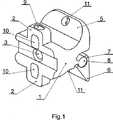
本発明による突起相互間距離保持インプラントは、アキソノメトリック投影法により図面に実施例として示されている。図1において、一つの不動性ウイングを有するインプラントが示され、図2に共同バンドと共に二つの可動性ウイングを有するインプラントが示され、図3にはアームを備えた二つの可動性ウイングを有するインプラントが示されている。 An inter-protrusion distance-retaining implant according to the invention is shown as an example in the drawing by means of an axonometric projection method. In Fig. 1 an implant with one immobile wing is shown, Fig. 2 shows an implant with two movable wings with a joint band and Fig. 3 an implant with two movable wings with arms. It is shown.
図1に呈示された突起相互間距離保持インプラントは、対峙して位置決めされた二つの抵抗突起2を有する後部で終端する本体1を有する。図1において、簡潔目的から示されたテンションバンド4のための貫通孔3が、本体1の軸において抵抗突起2に対して垂直に形成されている。抵抗突起2に対応する本体側から見て前部において、本体1は二つのウイングを有し、その内の一方の不動性ウイング5は軸に対して略垂直に位置決めされた本体の突起を構成し、他方の可動性ウイング6はローラに類似の本体1の形状面8に対する軸受けを構成する形状面7を有する。二つの形状面7および8間のリンクは、関節式結合により形成され、本体1に対する可動性ウイング6の回転を可能にし、かつ抵抗突起2が脊柱の隣接する脊椎の棘突起上に当接するまで突起相互間スペースへのインプラントの導入を容易にする。抵抗突起2はテンションバンド4を案内する手段を構成する貫通孔9および10を有する。テンションバンド4はインプラントに隣接する棘突起を取り囲み、かつウイング5および6内の貫通孔の形態のガイドを通過する。テンションバンド4の伸張後に、可動性ウイング6は回転して棘突起上に当接し、かつテンションバンド4の両端は結節に結合される。 The inter-protrusion distance-retaining implant presented in FIG. 1 has a
図2に示されたインプラントは、関節式結合により本体1に連結された二つの可動性ウイング6を有し、かつ二つの可動性ウイング6はウイング6の回転軸を構成するピン12により固定されている。本体1は本体の軸に平行の二つの貫通孔3を有する。本体1の抵抗突起2は、図1の実施例と同様に、テンションバンド4のための貫通孔9および10を有する。可動性ウイング6はテンションバンド4のために形成されたガイドを有する。可動性ウイング6のガイドは、同様にテンションバンド4のガイドを構成する溝15内に位置する孔13および凹部14の形態である。 The implant shown in FIG. 2 has two
図3の実施形態において、インプラントは二つの可動性ウイング6を備えた本体1を有する。本体1を有する関節式結合の領域において、各ウイング6は直角に近い角度αでウイング6に対して位置決めされた二つのアーム16を外側に具備する。本体1は二つの長手方向の貫通孔3を有し、かつ抵抗突起2は図3に示されていないテンションバンド4のための貫通孔9および10を有する。本体1の後部内の貫通孔3は、テンションバンド4の両端により形成された結節と共に座17で終端する。インプラントの開放状態において、可動性ウイング6のアーム16は本体1の軸受け面から外へ突出し、かつ棘突起を取り囲むテンションバンド4のテンション後に、アーム16は本体1の軸受け面の一要素を構成する。 In the embodiment of FIG. 3, the implant has a
Claims (6)
Translated fromJapanese各ウイング(5,6)はテンションバンド(4)の少なくとも一つのガイド(11,13,14,15)を有することを特徴とする突起相互間距離保持インプラント。In a protrusion-to-protrusion distance-retaining implant having a rear-terminated body with two oppositely located resistance protrusions having means for guiding the tension band, at least two wings (5 , 6) is located,Ri at least one mobile wing (6) der coupled to the body (1) by articulatedcoupling,
Inter-protrusion distance-retaining implant, characterized in thateach wing (5, 6) has at least one guide (11, 13, 14, 15) of a tension band (4) .
Applications Claiming Priority (3)
| Application Number | Priority Date | Filing Date | Title |
|---|---|---|---|
| PLP.377136 | 2005-09-19 | ||
| PL377136APL377136A1 (en) | 2005-09-19 | 2005-09-19 | Intervertebral space implant |
| PCT/PL2006/000059WO2007035120A1 (en) | 2005-09-19 | 2006-09-01 | Distance-keeping inter-process implant |
Publications (2)
| Publication Number | Publication Date |
|---|---|
| JP2009508570A JP2009508570A (en) | 2009-03-05 |
| JP4849694B2true JP4849694B2 (en) | 2012-01-11 |
Family
ID=37450900
Family Applications (1)
| Application Number | Title | Priority Date | Filing Date |
|---|---|---|---|
| JP2008531043AExpired - Fee RelatedJP4849694B2 (en) | 2005-09-19 | 2006-09-01 | Interprotrusion distance retention implant |
Country Status (10)
| Country | Link |
|---|---|
| US (3) | US8241332B2 (en) |
| EP (1) | EP1940305B1 (en) |
| JP (1) | JP4849694B2 (en) |
| AT (1) | ATE532471T1 (en) |
| AU (2) | AU2006292896A1 (en) |
| DK (1) | DK1940305T3 (en) |
| ES (1) | ES2377142T3 (en) |
| PL (2) | PL377136A1 (en) |
| PT (1) | PT1940305E (en) |
| WO (1) | WO2007035120A1 (en) |
Families Citing this family (42)
| Publication number | Priority date | Publication date | Assignee | Title |
|---|---|---|---|---|
| US8273108B2 (en) | 2004-10-20 | 2012-09-25 | Vertiflex, Inc. | Interspinous spacer |
| US8123782B2 (en) | 2004-10-20 | 2012-02-28 | Vertiflex, Inc. | Interspinous spacer |
| US9161783B2 (en) | 2004-10-20 | 2015-10-20 | Vertiflex, Inc. | Interspinous spacer |
| US8409282B2 (en) | 2004-10-20 | 2013-04-02 | Vertiflex, Inc. | Systems and methods for posterior dynamic stabilization of the spine |
| US8945183B2 (en) | 2004-10-20 | 2015-02-03 | Vertiflex, Inc. | Interspinous process spacer instrument system with deployment indicator |
| US8012207B2 (en) | 2004-10-20 | 2011-09-06 | Vertiflex, Inc. | Systems and methods for posterior dynamic stabilization of the spine |
| US8128662B2 (en) | 2004-10-20 | 2012-03-06 | Vertiflex, Inc. | Minimally invasive tooling for delivery of interspinous spacer |
| US9023084B2 (en) | 2004-10-20 | 2015-05-05 | The Board Of Trustees Of The Leland Stanford Junior University | Systems and methods for stabilizing the motion or adjusting the position of the spine |
| US8167944B2 (en) | 2004-10-20 | 2012-05-01 | The Board Of Trustees Of The Leland Stanford Junior University | Systems and methods for posterior dynamic stabilization of the spine |
| US8425559B2 (en) | 2004-10-20 | 2013-04-23 | Vertiflex, Inc. | Systems and methods for posterior dynamic stabilization of the spine |
| US9119680B2 (en) | 2004-10-20 | 2015-09-01 | Vertiflex, Inc. | Interspinous spacer |
| US8317864B2 (en) | 2004-10-20 | 2012-11-27 | The Board Of Trustees Of The Leland Stanford Junior University | Systems and methods for posterior dynamic stabilization of the spine |
| US8152837B2 (en) | 2004-10-20 | 2012-04-10 | The Board Of Trustees Of The Leland Stanford Junior University | Systems and methods for posterior dynamic stabilization of the spine |
| US8123807B2 (en) | 2004-10-20 | 2012-02-28 | Vertiflex, Inc. | Systems and methods for posterior dynamic stabilization of the spine |
| US8277488B2 (en) | 2004-10-20 | 2012-10-02 | Vertiflex, Inc. | Interspinous spacer |
| US7763074B2 (en) | 2004-10-20 | 2010-07-27 | The Board Of Trustees Of The Leland Stanford Junior University | Systems and methods for posterior dynamic stabilization of the spine |
| US8613747B2 (en) | 2004-10-20 | 2013-12-24 | Vertiflex, Inc. | Spacer insertion instrument |
| US8241330B2 (en) | 2007-01-11 | 2012-08-14 | Lanx, Inc. | Spinous process implants and associated methods |
| US9055981B2 (en) | 2004-10-25 | 2015-06-16 | Lanx, Inc. | Spinal implants and methods |
| EP2219538B1 (en) | 2004-12-06 | 2022-07-06 | Vertiflex, Inc. | Spacer insertion instrument |
| US8845726B2 (en) | 2006-10-18 | 2014-09-30 | Vertiflex, Inc. | Dilator |
| US9265532B2 (en) | 2007-01-11 | 2016-02-23 | Lanx, Inc. | Interspinous implants and methods |
| US9247968B2 (en) | 2007-01-11 | 2016-02-02 | Lanx, Inc. | Spinous process implants and associated methods |
| AU2008241447B2 (en) | 2007-04-16 | 2014-03-27 | Vertiflex, Inc. | Interspinous spacer |
| US9561060B2 (en)* | 2007-11-02 | 2017-02-07 | Zimmer Biomet Spine, Inc. | Interspinous implants with adjustable height spacer |
| WO2009083276A1 (en)* | 2008-01-03 | 2009-07-09 | Andrea Fontanella | Percutaneous interspinous process spacer |
| AU2009206098B2 (en) | 2008-01-15 | 2014-10-30 | Vertiflex, Inc. | Interspinous spacer |
| ITPI20080010A1 (en)* | 2008-02-07 | 2009-08-08 | Giuseppe Calvosa | INTERSTEIN VERTEBRAL DISTRACTOR FOR PERCUTANEOUS INSERTION |
| US8740948B2 (en) | 2009-12-15 | 2014-06-03 | Vertiflex, Inc. | Spinal spacer for cervical and other vertebra, and associated systems and methods |
| GB0922614D0 (en)* | 2009-12-23 | 2010-02-10 | Butterfield Forbes | Device |
| US20120323276A1 (en)* | 2011-06-17 | 2012-12-20 | Bryan Okamoto | Expandable interspinous device |
| US11812923B2 (en) | 2011-10-07 | 2023-11-14 | Alan Villavicencio | Spinal fixation device |
| US10709482B2 (en)* | 2012-05-30 | 2020-07-14 | Globus Medical, Inc. | Laminoplasty system |
| US9675303B2 (en) | 2013-03-15 | 2017-06-13 | Vertiflex, Inc. | Visualization systems, instruments and methods of using the same in spinal decompression procedures |
| AU2015256024B2 (en) | 2014-05-07 | 2020-03-05 | Vertiflex, Inc. | Spinal nerve decompression systems, dilation systems, and methods of using the same |
| KR101647446B1 (en)* | 2014-10-20 | 2016-08-10 | 주식회사 메드릭스 | Interspinous fusion implant |
| US10456174B2 (en) | 2017-07-31 | 2019-10-29 | Medos International Sarl | Connectors for use in systems and methods for reducing the risk of proximal junctional kyphosis |
| US10463403B2 (en) | 2017-07-31 | 2019-11-05 | Medos International Sarl | Systems and methods for reducing the risk of proximal junctional kyphosis using a bone anchor or other attachment point |
| CN213098543U (en)* | 2020-06-24 | 2021-05-04 | 好喜欢妮有限公司 | Interspinous process fixing device |
| WO2023158581A1 (en) | 2022-02-15 | 2023-08-24 | Boston Scientific Neuromodulation Corporation | Interspinous spacer and systems utilizing the interspinous spacer |
| US12433646B2 (en) | 2023-02-21 | 2025-10-07 | Boston Scientific Neuromodulation Corporation | Interspinous spacer with actuator locking arrangements and methods and systems |
| US12390340B2 (en) | 2023-03-15 | 2025-08-19 | Boston Scientific Neuromodulation Corporation | Interspinous spacer with a range of deployment positions and methods and systems |
Family Cites Families (36)
| Publication number | Priority date | Publication date | Assignee | Title |
|---|---|---|---|---|
| CA1283501C (en) | 1987-02-12 | 1991-04-30 | Thomas P. Hedman | Artificial spinal disc |
| US5496318A (en)* | 1993-01-08 | 1996-03-05 | Advanced Spine Fixation Systems, Inc. | Interspinous segmental spine fixation device |
| US5282801A (en) | 1993-02-17 | 1994-02-01 | Danek Medical, Inc. | Top tightening clamp assembly for a spinal fixation system |
| FR2721501B1 (en) | 1994-06-24 | 1996-08-23 | Fairant Paulette | Prostheses of the vertebral articular facets. |
| US7959652B2 (en)* | 2005-04-18 | 2011-06-14 | Kyphon Sarl | Interspinous process implant having deployable wings and method of implantation |
| US20050245937A1 (en)* | 2004-04-28 | 2005-11-03 | St. Francis Medical Technologies, Inc. | System and method for insertion of an interspinous process implant that is rotatable in order to retain the implant relative to the spinous processes |
| US6156038A (en) | 1997-01-02 | 2000-12-05 | St. Francis Medical Technologies, Inc. | Spine distraction implant and method |
| US7306628B2 (en) | 2002-10-29 | 2007-12-11 | St. Francis Medical Technologies | Interspinous process apparatus and method with a selectably expandable spacer |
| US6068630A (en) | 1997-01-02 | 2000-05-30 | St. Francis Medical Technologies, Inc. | Spine distraction implant |
| US6451019B1 (en) | 1998-10-20 | 2002-09-17 | St. Francis Medical Technologies, Inc. | Supplemental spine fixation device and method |
| US5860977A (en) | 1997-01-02 | 1999-01-19 | Saint Francis Medical Technologies, Llc | Spine distraction implant and method |
| EP1867293A2 (en) | 1997-10-27 | 2007-12-19 | St. Francis Medical Technologies, Inc. | Spine distraction implant |
| FR2774581B1 (en) | 1998-02-10 | 2000-08-11 | Dimso Sa | INTEREPINOUS STABILIZER TO BE ATTACHED TO SPINOUS APOPHYSIS OF TWO VERTEBRES |
| FR2775183B1 (en) | 1998-02-20 | 2000-08-04 | Jean Taylor | INTER-SPINOUS PROSTHESIS |
| FR2799640B1 (en) | 1999-10-15 | 2002-01-25 | Spine Next Sa | IMPLANT INTERVETEBRAL |
| FR2818530B1 (en) | 2000-12-22 | 2003-10-31 | Spine Next Sa | INTERVERTEBRAL IMPLANT WITH DEFORMABLE SHIM |
| CA2437575C (en) | 2001-02-16 | 2009-04-07 | Queen's University At Kingston | Method and device for treating abnormal curvature of the spine |
| FR2822051B1 (en) | 2001-03-13 | 2004-02-27 | Spine Next Sa | INTERVERTEBRAL IMPLANT WITH SELF-LOCKING ATTACHMENT |
| US7048736B2 (en) | 2002-05-17 | 2006-05-23 | Sdgi Holdings, Inc. | Device for fixation of spinous processes |
| FR2844179B1 (en) | 2002-09-10 | 2004-12-03 | Jean Taylor | POSTERIOR VERTEBRAL SUPPORT KIT |
| US8070778B2 (en) | 2003-05-22 | 2011-12-06 | Kyphon Sarl | Interspinous process implant with slide-in distraction piece and method of implantation |
| US20060064165A1 (en) | 2004-09-23 | 2006-03-23 | St. Francis Medical Technologies, Inc. | Interspinous process implant including a binder and method of implantation |
| US8147548B2 (en) | 2005-03-21 | 2012-04-03 | Kyphon Sarl | Interspinous process implant having a thread-shaped wing and method of implantation |
| US7931674B2 (en) | 2005-03-21 | 2011-04-26 | Kyphon Sarl | Interspinous process implant having deployable wing and method of implantation |
| US7909853B2 (en)* | 2004-09-23 | 2011-03-22 | Kyphon Sarl | Interspinous process implant including a binder and method of implantation |
| AU2003210887A1 (en) | 2003-02-06 | 2004-09-06 | Archus Orthopedics Inc. | Facet arthroplasty devices and methods |
| FR2851154B1 (en) | 2003-02-19 | 2006-07-07 | Sdgi Holding Inc | INTER-SPINOUS DEVICE FOR BRAKING THE MOVEMENTS OF TWO SUCCESSIVE VERTEBRATES, AND METHOD FOR MANUFACTURING THE SAME THEREOF |
| US7481839B2 (en) | 2003-12-02 | 2009-01-27 | Kyphon Sarl | Bioresorbable interspinous process implant for use with intervertebral disk remediation or replacement implants and procedures |
| US7524324B2 (en)* | 2004-04-28 | 2009-04-28 | Kyphon Sarl | System and method for an interspinous process implant as a supplement to a spine stabilization implant |
| US8409282B2 (en)* | 2004-10-20 | 2013-04-02 | Vertiflex, Inc. | Systems and methods for posterior dynamic stabilization of the spine |
| EP1807012B1 (en) | 2004-10-25 | 2016-07-06 | Lanx, LLC | Nterspinous distraction devices |
| AU2005316646B2 (en) | 2004-12-13 | 2011-09-15 | Kyphon Sarl | Inter-facet implant |
| US8403959B2 (en) | 2004-12-16 | 2013-03-26 | Med-Titan Spine Gmbh | Implant for the treatment of lumbar spinal canal stenosis |
| ES2556111T3 (en)* | 2005-04-08 | 2016-01-13 | Paradigm Spine, Llc | Interspinous vertebral and lumbosacral stabilization devices |
| US7780709B2 (en)* | 2005-04-12 | 2010-08-24 | Warsaw Orthopedic, Inc. | Implants and methods for inter-transverse process dynamic stabilization of a spinal motion segment |
| US20070055373A1 (en)* | 2005-09-08 | 2007-03-08 | Zimmer Spine, Inc. | Facet replacement/spacing and flexible spinal stabilization |
- 2005
- 2005-09-19PLPL377136Apatent/PL377136A1/ennot_activeApplication Discontinuation
- 2006
- 2006-09-01WOPCT/PL2006/000059patent/WO2007035120A1/enactiveApplication Filing
- 2006-09-01JPJP2008531043Apatent/JP4849694B2/ennot_activeExpired - Fee Related
- 2006-09-01ESES06784041Tpatent/ES2377142T3/enactiveActive
- 2006-09-01DKDK06784041.3Tpatent/DK1940305T3/enactive
- 2006-09-01USUS11/992,206patent/US8241332B2/ennot_activeExpired - Fee Related
- 2006-09-01PTPT06784041Tpatent/PT1940305E/enunknown
- 2006-09-01AUAU2006292896Apatent/AU2006292896A1/ennot_activeAbandoned
- 2006-09-01EPEP06784041Apatent/EP1940305B1/ennot_activeNot-in-force
- 2006-09-01ATAT06784041Tpatent/ATE532471T1/enactive
- 2006-09-01PLPL06784041Tpatent/PL1940305T3/enunknown
- 2010
- 2010-12-22AUAU2010257367Apatent/AU2010257367B2/ennot_activeCeased
- 2012
- 2012-05-09USUS13/467,914patent/US8403960B2/ennot_activeExpired - Fee Related
- 2013
- 2013-03-25USUS13/850,290patent/US8979899B2/ennot_activeExpired - Fee Related
Also Published As
| Publication number | Publication date |
|---|---|
| US20130238029A1 (en) | 2013-09-12 |
| ATE532471T1 (en) | 2011-11-15 |
| US20120221052A1 (en) | 2012-08-30 |
| EP1940305B1 (en) | 2011-11-09 |
| US8403960B2 (en) | 2013-03-26 |
| EP1940305A1 (en) | 2008-07-09 |
| ES2377142T3 (en) | 2012-03-22 |
| PT1940305E (en) | 2012-02-13 |
| JP2009508570A (en) | 2009-03-05 |
| WO2007035120A1 (en) | 2007-03-29 |
| AU2006292896A1 (en) | 2007-03-29 |
| AU2010257367B2 (en) | 2012-02-09 |
| WO2007035120A8 (en) | 2007-05-10 |
| AU2010257367A1 (en) | 2011-01-20 |
| US8979899B2 (en) | 2015-03-17 |
| DK1940305T3 (en) | 2012-03-05 |
| US20090138045A1 (en) | 2009-05-28 |
| PL1940305T3 (en) | 2012-04-30 |
| US8241332B2 (en) | 2012-08-14 |
| PL377136A1 (en) | 2007-04-02 |
Similar Documents
| Publication | Publication Date | Title |
|---|---|---|
| JP4849694B2 (en) | Interprotrusion distance retention implant | |
| JP4887360B2 (en) | Cervical anterior plate | |
| ES2462490T3 (en) | Patella resection guide with location features | |
| US6159217A (en) | Trochlear clamp | |
| JP3542487B2 (en) | Tibial resection guide | |
| JP7341889B2 (en) | proximal femoral hook plate | |
| US11006948B2 (en) | Surgical staple and instrument for holding and implanting the surgical staple | |
| RU2570967C2 (en) | Anterior spinal implant, implant guide instrument and method for installing it | |
| JP5449316B2 (en) | Joint fixation system for ankles of human patients | |
| KR20040028562A (en) | Laminoplasty cage | |
| US20130253516A1 (en) | Occipital plate | |
| ES2959749T3 (en) | Osteotomy device with an in vitro alignment component | |
| ES2379332T3 (en) | Orthopedic support device for a knee joint | |
| JP7493529B2 (en) | Fusion systems, instruments, bone plates and methods of use | |
| KR20100095044A (en) | A apparatus of spinal surgical operation for minimally invasive surgery | |
| CN101801287B (en) | Surgical instrument attachment | |
| EP4009892B1 (en) | Dynamic bone plate | |
| EP3701892B1 (en) | Guide device for attachment and transfixation of sliding plates for dynamic implants | |
| JP7670308B2 (en) | Cervical orthotics | |
| JPWO2020144537A5 (en) |
Legal Events
| Date | Code | Title | Description |
|---|---|---|---|
| A977 | Report on retrieval | Free format text:JAPANESE INTERMEDIATE CODE: A971007 Effective date:20110126 | |
| A131 | Notification of reasons for refusal | Free format text:JAPANESE INTERMEDIATE CODE: A131 Effective date:20110201 | |
| A601 | Written request for extension of time | Free format text:JAPANESE INTERMEDIATE CODE: A601 Effective date:20110427 | |
| A602 | Written permission of extension of time | Free format text:JAPANESE INTERMEDIATE CODE: A602 Effective date:20110510 | |
| A521 | Request for written amendment filed | Free format text:JAPANESE INTERMEDIATE CODE: A523 Effective date:20110721 | |
| TRDD | Decision of grant or rejection written | ||
| A01 | Written decision to grant a patent or to grant a registration (utility model) | Free format text:JAPANESE INTERMEDIATE CODE: A01 Effective date:20110816 | |
| A01 | Written decision to grant a patent or to grant a registration (utility model) | Free format text:JAPANESE INTERMEDIATE CODE: A01 | |
| A521 | Request for written amendment filed | Free format text:JAPANESE INTERMEDIATE CODE: A523 Effective date:20110912 | |
| A601 | Written request for extension of time | Free format text:JAPANESE INTERMEDIATE CODE: A601 Effective date:20110915 | |
| A602 | Written permission of extension of time | Free format text:JAPANESE INTERMEDIATE CODE: A602 Effective date:20110928 | |
| A61 | First payment of annual fees (during grant procedure) | Free format text:JAPANESE INTERMEDIATE CODE: A61 Effective date:20111017 | |
| R150 | Certificate of patent or registration of utility model | Free format text:JAPANESE INTERMEDIATE CODE: R150 | |
| FPAY | Renewal fee payment (event date is renewal date of database) | Free format text:PAYMENT UNTIL: 20141028 Year of fee payment:3 | |
| R250 | Receipt of annual fees | Free format text:JAPANESE INTERMEDIATE CODE: R250 | |
| R250 | Receipt of annual fees | Free format text:JAPANESE INTERMEDIATE CODE: R250 | |
| R250 | Receipt of annual fees | Free format text:JAPANESE INTERMEDIATE CODE: R250 | |
| R250 | Receipt of annual fees | Free format text:JAPANESE INTERMEDIATE CODE: R250 | |
| LAPS | Cancellation because of no payment of annual fees |