JP4845551B2 - Cable clamp - Google Patents
Cable clampDownload PDFInfo
- Publication number
- JP4845551B2 JP4845551B2JP2006082266AJP2006082266AJP4845551B2JP 4845551 B2JP4845551 B2JP 4845551B2JP 2006082266 AJP2006082266 AJP 2006082266AJP 2006082266 AJP2006082266 AJP 2006082266AJP 4845551 B2JP4845551 B2JP 4845551B2
- Authority
- JP
- Japan
- Prior art keywords
- cable
- base
- pair
- clamp
- cable clamp
- Prior art date
- Legal status (The legal status is an assumption and is not a legal conclusion. Google has not performed a legal analysis and makes no representation as to the accuracy of the status listed.)
- Expired - Fee Related
Links
Images


Classifications
- H—ELECTRICITY
- H02—GENERATION; CONVERSION OR DISTRIBUTION OF ELECTRIC POWER
- H02G—INSTALLATION OF ELECTRIC CABLES OR LINES, OR OF COMBINED OPTICAL AND ELECTRIC CABLES OR LINES
- H02G3/00—Installations of electric cables or lines or protective tubing therefor in or on buildings, equivalent structures or vehicles
- H02G3/30—Installations of cables or lines on walls, floors or ceilings
- G—PHYSICS
- G02—OPTICS
- G02B—OPTICAL ELEMENTS, SYSTEMS OR APPARATUS
- G02B6/00—Light guides; Structural details of arrangements comprising light guides and other optical elements, e.g. couplings
- G02B6/44—Mechanical structures for providing tensile strength and external protection for fibres, e.g. optical transmission cables
- G02B6/4439—Auxiliary devices
- G02B6/444—Systems or boxes with surplus lengths
- G02B6/4452—Distribution frames
- G02B6/44524—Distribution frames with frame parts or auxiliary devices mounted on the frame and collectively not covering a whole width of the frame or rack
- G—PHYSICS
- G02—OPTICS
- G02B—OPTICAL ELEMENTS, SYSTEMS OR APPARATUS
- G02B6/00—Light guides; Structural details of arrangements comprising light guides and other optical elements, e.g. couplings
- G02B6/44—Mechanical structures for providing tensile strength and external protection for fibres, e.g. optical transmission cables
- G02B6/4439—Auxiliary devices
- G02B6/444—Systems or boxes with surplus lengths
- G02B6/44528—Patch-cords; Connector arrangements in the system or in the box
- G—PHYSICS
- G02—OPTICS
- G02B—OPTICAL ELEMENTS, SYSTEMS OR APPARATUS
- G02B6/00—Light guides; Structural details of arrangements comprising light guides and other optical elements, e.g. couplings
- G02B6/44—Mechanical structures for providing tensile strength and external protection for fibres, e.g. optical transmission cables
- G02B6/4439—Auxiliary devices
- G02B6/4471—Terminating devices ; Cable clamps
- G02B6/44785—Cable clamps
- H—ELECTRICITY
- H02—GENERATION; CONVERSION OR DISTRIBUTION OF ELECTRIC POWER
- H02G—INSTALLATION OF ELECTRIC CABLES OR LINES, OR OF COMBINED OPTICAL AND ELECTRIC CABLES OR LINES
- H02G3/00—Installations of electric cables or lines or protective tubing therefor in or on buildings, equivalent structures or vehicles
- H02G3/30—Installations of cables or lines on walls, floors or ceilings
- H02G3/32—Installations of cables or lines on walls, floors or ceilings using mounting clamps
Landscapes
- Physics & Mathematics (AREA)
- General Physics & Mathematics (AREA)
- Optics & Photonics (AREA)
- Engineering & Computer Science (AREA)
- Architecture (AREA)
- Civil Engineering (AREA)
- Structural Engineering (AREA)
- Insertion, Bundling And Securing Of Wires For Electric Apparatuses (AREA)
- Light Guides In General And Applications Therefor (AREA)
- Installation Of Indoor Wiring (AREA)
Description
Translated fromJapanese本発明は、通信機器や電子機器などでケーブルを保持するケーブル用クランプに関し、特に極細線ケーブルの固定処理に適したケーブル用クランプに関する。 The present invention relates to a cable clamp that holds a cable in a communication device, an electronic device, or the like, and more particularly to a cable clamp that is suitable for fixing processing of a fine wire cable.
近年、通信機器や電子機器などにおいては通信容量の大容量化が要請されており、また製造上の進歩により装置内部に搭載する伝送ケーブルの細線化が進んでいる。特に通信機器においては、高速で安定した通信品質を提供するために、光ファイバケーブルによる光伝送が主流になってきている。光通信ユニットにおいては、そのような光ファイバケーブルを内部で固定したり余長部分を纏めたりということが行われており、そのような光ファイバケーブルの処理にはケーブル用クランプが用いられている。 In recent years, communication devices, electronic devices, and the like have been required to have a large communication capacity, and due to progress in manufacturing, transmission cables mounted inside the device are becoming thinner. In particular, in communication equipment, optical transmission using optical fiber cables has become mainstream in order to provide high-speed and stable communication quality. In an optical communication unit, such an optical fiber cable is fixed internally or an extra length portion is gathered, and a cable clamp is used for processing such an optical fiber cable. .
図4は一般的なケーブルを処理するための従来のケーブル用クランプの例を示す図であって、(A)はM型クランプを示し、(B)は開閉式クランプを示し、(C)はツイスト式クランプを示している。 FIG. 4 is a view showing an example of a conventional cable clamp for processing a general cable, in which (A) shows an M-type clamp, (B) shows an open / close clamp, and (C) shows A twist clamp is shown.
同図の(A)に示すM型クランプ101は、中央の部分が開放されていて、その開放部分へガイドするよう内側に傾斜されており、シャシまたはプリント配線基板へ固定するための固定手段を有している。ケーブル100は、そのM型クランプ101の中央の開放部分へ押し込まれることで内部に挿入され、保持される。 The M-
(B)に示す開閉式クランプ102は、上部が開閉できる開閉機構を有しているものである。ケーブル100は、開閉式クランプ102の開閉機構を開けて内部に収容し、その後開閉機構を閉じることによって保持される。 The open /
そして、(C)に示すツイスト式クランプ103は、両端に掛止部を有する紐状のものである。ケーブル100は、あらかじめ開放されたツイスト式クランプ103に収容後にそのツイスト式クランプ103をツイストさせることで結束され、保持される。 And the
図5は従来のケーブル用クランプを用いた光通信ユニットの一構成例を示す斜視図、図6は上記の従来の開閉式クランプによる光ファイバケーブルの処理の様子を示す斜視図であって、(A)は開閉機構を開けた状態を示し、(B)は開閉機構を閉じた状態を示している。 FIG. 5 is a perspective view showing a configuration example of an optical communication unit using a conventional cable clamp, and FIG. 6 is a perspective view showing a state of processing of an optical fiber cable by the conventional open / close clamp. A) shows a state in which the opening / closing mechanism is opened, and (B) shows a state in which the opening / closing mechanism is closed.
図5に示した光通信ユニットでは、図4の(B)に示す開閉式クランプ102を用いた場合を示している。開閉式クランプ102は、光通信ユニット内のプリント配線基板104等の所定箇所に固定配置されており、内部に導入された光ファイバケーブル105の固定処理及び余長処理を行うようにしている。 The optical communication unit shown in FIG. 5 shows a case where the open /
その光ファイバケーブル105の固定処理及び余長処理は、図6の(A)に示したように開閉機構を開けた状態で光ファイバケーブル105を収容し、その後(B)に示すように開閉機構を閉じることによって行われる。 The fixing process and the extra length process of the
また、特にフラットケーブルを処理するのに適したケーブル用クランプも提案されている(例えば特許文献1参照)。このケーブル用クランプは、ケーブルを挟む挟持板とガイドバーからなり、ケーブルを挟持板に挟んで回転させることにより保持するものである。このケーブル用クランプの場合、ケーブル自体に外圧を与えて押さえ込むことによりケーブルを固定する。
しかしながら、上記のような従来のケーブル用クランプにおいては、光ファイバケーブルを処理するにはあまり適していない。すなわち、光ファイバケーブルは、ブロードバンド時代に対応できる超高速・大容量化に伴って、直径が0.9mm、0.4mmから0.25mmへと極細化してきている。このような線径のケーブルは、透明に極めて近いものもあり、釣り糸のように目視での確認がしづらく、固定処理や余長処理で絡まったり、引っかかったり、あるいは挟んだりして、作業性が困難なものになっており、断線しやすいものとなっている。このような極細線ケーブルを従来のケーブル用クランプで処理する場合、ケーブルが外れたり、はみ出したりしやすく、また、断線しやすいという問題点がある。 However, the conventional cable clamps as described above are not very suitable for processing optical fiber cables. In other words, optical fiber cables have become extremely thin from 0.9 mm, 0.4 mm to 0.25 mm, as ultra-high speed and large capacity that can cope with the broadband age. Some cables with such wire diameters are very close to transparency, and are difficult to check visually like fishing lines, entangled, caught or pinched by fixing or extra length processing, and workability Is difficult, and it is easy to break. When such a fine wire cable is processed by a conventional cable clamp, there is a problem that the cable is easily detached or protrudes and is easily disconnected.
例えば、M型クランプでは、中央が開放されているのでそこから収容されているケーブルが外れやすく、ケーブルが外れた場合に装置内で引っかかって断線の原因となる。開閉式クランプでは、開閉機構によりロックする構造であるため、図6に示すようにケーブルがフック部に引っかかったり、はみ出したりして、同様に断線の原因となる。これは特に、ケーブルを余長処理のためにループ状に複数回巻くときに起こりやすく、また作業性も悪く、ケーブルが長い場合には余長処理の巻き数も多くなり、手間がかかる。ツイスト式クランプでは、ケーブルを収容後、ツイストさせるため、特に細いケーブルの処理では作業性が悪い。 For example, in the M-type clamp, since the center is opened, the cable accommodated from the center is easily disconnected, and when the cable is disconnected, it is caught in the apparatus and causes disconnection. Since the open / close clamp has a structure in which it is locked by an open / close mechanism, the cable is caught in or protrudes from the hook portion as shown in FIG. This is particularly likely to occur when a cable is wound in a loop for a surplus length process, and the workability is poor. If the cable is long, the number of extra length windings increases, which is troublesome. In the twist type clamp, since the cable is twisted after being accommodated, the workability is particularly poor when processing a thin cable.
本発明は、このような点に鑑みてなされたものであり、極細線ケーブルを処理する場合でも、ケーブルが外れたり、はみ出したりするのを防止することができ、ケーブルの損傷や断線の虞がなく、またケーブルの固定処理及び余長処理が容易で、作業性の良いケーブル用クランプを提供することを目的とする。 The present invention has been made in view of the above points, and even when processing an ultra-thin wire cable, the cable can be prevented from coming off or protruding, and there is a risk of damage or disconnection of the cable. It is another object of the present invention to provide a cable clamp that is easy to fix and process a cable length and has good workability.
上記課題を解決するために、図1に示したように、本発明の一実施態様によるケーブル用クランプ10は、円板状に形成された基台11を有し、その基台11の上にほぼ逆さL字形状の一対のケーブル保持体12,13を有している。これらのケーブル保持体12,13は、基台11から垂直方向に伸びた柱部12a,13aとこの柱部12a,13aから基台11の面に平行な方向に伸びた片梁部12b,13bとを有している。一対のケーブル保持体12,13は、それぞれの片梁部12b,13bの一方の側面が所定の間隔を持って相対向するように互いに逆向きで柱部12a,13aが配置されている。基台11のケーブル保持体12,13が設けられている側と反対側の中央には、取り付け板に貫通して配置されるアンカー部15が設けられ、これが取り付け板に取り付けられたときに、ケーブル用クランプ10の回転中心となる。 In order to solve the above-mentioned problem, as shown in FIG. 1, a
取り付け板にアンカー部15を貫通して配置し、所定の間隔を持って相対向する片梁部12b,13bの間の隙間の向きを固定しようとするケーブルの向きになるようケーブル用クランプ10を回転しておく。片梁部12b,13bの間の隙間を介してケーブル保持体12,13の内部にケーブルを収容した後にケーブル保持体12,13を摘まんで回転させることで、ケーブルを挿入する隙間とケーブルとを直交させる。これにより、ケーブルが外れたり、はみ出したりすることを防止することができ、ケーブルの損傷や断線の虞がなく、またケーブルの固定処理及び余長処理が容易で、作業性が良い。 The
本発明のケーブル用クランプは、柱部と片梁部とからなる一対のケーブル保持体を柱部が互いに逆向きでそれぞれの片梁部の側面が所定の間隔を持って相対向するように配置したから、極細線ケーブルを処理する場合でも、一対のケーブル保持体の内部にケーブルを収容した後に一対のケーブル保持体を回転させることで、ケーブルが外れたり、はみ出したりするのを防止することができ、ケーブルの損傷や断線の虞がなく、またケーブルの固定処理及び余長処理が容易で、作業性が良いという利点がある。 The cable clamp according to the present invention has a pair of cable holders composed of a pillar portion and a single beam portion arranged such that the pillar portions are opposite to each other and the side surfaces of the respective single beam portions are opposed to each other with a predetermined interval. Therefore, even when processing extra fine wire cables, it is possible to prevent the cables from coming off or protruding by rotating the pair of cable holders after the cables are accommodated in the pair of cable holders. There is no possibility of cable damage or disconnection, and there are advantages that the cable fixing process and the extra length process are easy and workability is good.
以下、本発明の実施の形態を図面を参照して説明する。
図1は本発明の実施の形態に係るケーブル用クランプの構造を示す図であって、(A)は平面図、(B)は正面図、(C)は右側面図である。このケーブル用クランプ10は、ベースとなる基台11に固定された一対のケーブル保持体12,13を有している。この一対のケーブル保持体12,13はそれぞれ、基台11から垂直方向に伸びた柱部12a,13aと、柱部12a,13aの基台11と反対側から柱部12a,13aと略直角方向に伸びた片梁部12b,13bからなる逆さL字形あるいは円弧状の形状となっている。Hereinafter, embodiments of the present invention will be described with reference to the drawings.
1A and 1B are diagrams showing a structure of a cable clamp according to an embodiment of the present invention. FIG. 1A is a plan view, FIG. 1B is a front view, and FIG. 1C is a right side view. The
上記一対のケーブル保持体12,13は、柱部12a,13aが互いに逆向きでそれぞれの片梁部12b,13bの一方の側面が所定の間隔を持って相対向するように配置されている。この間隔は、極細線ケーブルを挿入するためのものである。 The pair of
また、一対のケーブル保持体12,13の相対向する片梁部12b,13bの少なくとも何れかの側面には、鋸歯状の複数の凸部14が設けられている。この凸部14は、極細線ケーブルの挿入性の確保と飛び出し及びはみ出し防止のためであり、基台11の方向(下方向)に傾斜した形状となっている。この例では、ケーブル保持体12の一方の片梁部12bの側面に凸部14が設けられている。さらに、片梁部12b,13bの基台11と反対側の端部には相対向する傾斜面12c,13cが設けられている。この傾斜面12c,13cは、極細線ケーブルの位置合わせと挿入をスムーズに行うためのガイド面を構成している。 A plurality of sawtooth-shaped
また、基台11は円板状に形成され、一対のケーブル保持体12,13と反対側の裏面(下面)の中央部にはアンカー部15が設けられている。このアンカー部15は、図示しない取り付け板に設けられた装着孔に押し込まれてこのケーブル用クランプ10を取り付け板に取り付けるためのもので、先端に抜け防止用の開脚部分を有しており、装着孔への挿入後は、このケーブル用クランプ10の回転中心軸を構成する。さらに、基台11の裏面の周囲部には、二つの突起部16と二つの隆起部17とが円周方向に交互に配置されている。突起部16は、ケーブル用クランプ10を装着孔に装着後、そのアンカー部15を中心に回転するとき、取り付け板に設けられた係合孔を乗り越えて一方向に回転可能なようにテーパが付けられている。 The
図2はケーブル用クランプの取り付け手順及び処理手順を示す図である。
ケーブル用クランプ10が取り付けられるプリント回路基板などの取り付け板20には、装着孔21が設けられており、その装着孔21を中心とした同心円上には四つの係合穴22が設けられている。FIG. 2 is a diagram showing a cable clamp attachment procedure and processing procedure.
A mounting
ケーブル用クランプ10を取り付け板20に取り付けるには、まず、同図の(A)に示すように、円板状の基台11の下面に設けられたアンカー部15を取り付け板20に形成された装着孔21に矢印方向に差し込んで取り付ける。このアンカー部15は開脚形状となっているので、取り付け板20から容易に抜けることはない。このとき、ケーブル用クランプ10は、柱部12a,13aから片梁部12b,13bが伸びている方向を保持しようとする極細線ケーブル1が伸びている方向に合わせるように回転され、このとき、突起部16が対応する係合穴22に係合されるので、容易に回転されない。 In order to attach the
次に、(B)に示すように、ケーブル用クランプ10の一対のケーブル保持体12,13の片梁部12b,13bの隙間から極細線ケーブル1を挿入する。その後、ケーブル保持体12,13の片梁部12b,13bの両端を持って矢印方向(時計回り方向)に90度回転させる。これにより、(C)に示すように、極細線ケーブル1は一対のケーブル保持体12,13と基台11との間に確実に収容され、外部に飛び出したりはみ出したりすることはない。したがって、極細線ケーブル1を取り逃がすことなく、確実に固定することができる。 Next, as shown in (B), the ultrafine wire cable 1 is inserted from the gap between the
また、ケーブル用クランプ10を90度回転させたときに、基台11の裏面の突起部16と取り付け板20の係合穴22とが係合してロックされるので、位置合わせが容易である。その際、突起部16は回転方向に低いテーパが付けられているので、回転方向には回転しやすく、逆方向(反時計回り方向)には回転しにくい構造となっている。 Further, when the
このように、一対のケーブル保持体12,13の内部に極細線ケーブル1を収容した後にケーブル用クランプ10を回転させることで、極細線ケーブル1が伸びている方向と極細線ケーブル1を挿入する隙間の方向とが直交しているので、極細線ケーブル1を確実に固定することができる。その際、ロック構造や開閉機構などの可動部を有していないので、極細線ケーブル1がクランプ本体に引っかかることなく、素早く極細線ケーブル1を装着することができる。したがって、極細線ケーブル1が外れたり、はみ出したりするのを防止することができ、極細線ケーブル1の損傷や断線の虞がない。また、極細線ケーブル1の固定処理及び余長処理が容易で、作業性が良く、ケーブル保持体12,13を使用した高品質の製品を提供することができる。 As described above, after the ultrafine wire cable 1 is accommodated in the pair of
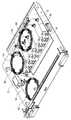
図3はケーブル用クランプを用いた光通信ユニットの構成例を示す斜視図である。
光通信ユニットには、プリント配線基板2、光デバイス3、中継アダプタ4等が実装されており、極細の光ファイバケーブル1aが配置されるべき所要位置にケーブル用クランプ10が固定されている。この光通信ユニットの組み立ては、光デバイス3が取り付けられた後、光ファイバケーブル1aの余長処理と中継アダプタ4の接続を行う。このとき、配線のために光ファイバケーブル1aの余長処理を行うが、ケーブル用クランプ10を用いることにより、光ファイバケーブル1aを容易に収容することができ、組み立て、製造が容易である。また、この光通信ユニットは通常、装置本体(シェルフ)に挿入して使用するが、光ファイバケーブル1aがケーブル用クランプ10からはみ出すことはなく、確実に固定できるので、断線の心配もない。したがって、高品質の光通信ユニットを実現することができる。FIG. 3 is a perspective view showing a configuration example of an optical communication unit using a cable clamp.
A printed
ここで、実施の形態のケーブル用クランプ10は、上部から光ファイバケーブル1aを挿入できる単純構造であり、収容する光ファイバケーブル1aの固定本数に応じて一対のケーブル保持体12,13の柱部12a,13aの高さを決めることができるので、低背(ロープロファイル)構造での構成が容易である。このため、小型化を図ることができ、小型の電子機器にも対応することができ、汎用性の高いものとなる。 Here, the
また、ケーブル用クランプ10の取り付け及び回転のロック機構のために取り付け板20に形成する装着孔21及び係合穴22は円形穴とすることができ、容易にドリルでの穴開けが可能となり、特殊穴抜きを必要とせず、低コストで製造することができる。 In addition, the mounting
1 極細線ケーブル
1a 光ファイバケーブル
10 ケーブル用クランプ
11 基台
12,13 ケーブル保持体
12a,13a 柱部
12b,13b 片梁部
12c,13c 傾斜面
14 凸部
15 アンカー部
16 突起部
17 隆起部
20 取り付け板
21 装着孔
22 係合穴DESCRIPTION OF SYMBOLS 1 Extra
Claims (4)
Translated fromJapanese基台と、
前記基台上の所定間隔を置いた位置からそれぞれ垂直方向に伸びた柱部及び前記柱部の前記基台と反対側の端部から前記柱部と略直角方向に伸びていてそれぞれの一方の側面が所定の間隔を持って相対向して配置された片梁部を有し、一対の前記片梁部の相対向する少なくとも何れかの側面には複数の凸部が設けられた、一対のケーブル保持体と、
前記柱部とは反対側にて前記基台の中心から垂直方向に伸びていて取り付け板に貫通して配置されるアンカー部と、
を備え、前記基台の裏面の周囲に複数の突起物を配置して前記取り付け板の係合穴に係合させ、前記一対のケーブル保持体は、前記片梁部の間の前記間隔に前記ケーブルを挿入するときの前記片梁部の伸びの方向を、前記アンカー部を中心に前記基台を回転することによって変更できるようにし、前記ケーブルの延びる方向に対し、一対の前記片梁部の伸びの方向を直交させて、前記ケーブルを固定させたことを特徴とするケーブル用クランプ。In the cable clamp that holds the cable,
The base,
Columns extending in a vertical direction from positions spaced apart from each other on the base, and one end of each of the pillars extending in a direction substantially perpendicular to the column from the end opposite to the base. sideshave a piece beam portions which are opposed to each other with a predeterminedinterval, a plurality of convex portions are provided on at least one side surface opposing the pair of the pieces beam portions, a pair A cable holder;
An anchor portion that extends in the vertical direction from the center of the base on the side opposite to the column portion and is disposed through the mounting plate;
Aplurality of protrusions are arranged around the back surface of the base and engaged with the engagement holes of the mounting plate, and the pair of cable holders arearranged at the interval between the single beam portions. The direction of extension of the single beam part when inserting a cable can be changed by rotating the base around the anchor part, and the pair of single beam parts is A cable clamp characterizedin that thecable is fixed with the direction of elongation orthogonal .
Before Symbol anchor portion, the cable clamp according to claim 1, characterized in that it has a open leg portions for preventing leakage at the tip.
Priority Applications (3)
| Application Number | Priority Date | Filing Date | Title |
|---|---|---|---|
| JP2006082266AJP4845551B2 (en) | 2006-03-24 | 2006-03-24 | Cable clamp |
| CNB200610128964XACN100511892C (en) | 2006-03-24 | 2006-09-05 | Cable clamp |
| US11/520,825US7527226B2 (en) | 2006-03-24 | 2006-09-14 | Cable clamp |
Applications Claiming Priority (1)
| Application Number | Priority Date | Filing Date | Title |
|---|---|---|---|
| JP2006082266AJP4845551B2 (en) | 2006-03-24 | 2006-03-24 | Cable clamp |
Publications (2)
| Publication Number | Publication Date |
|---|---|
| JP2007259618A JP2007259618A (en) | 2007-10-04 |
| JP4845551B2true JP4845551B2 (en) | 2011-12-28 |
Family
ID=38532340
Family Applications (1)
| Application Number | Title | Priority Date | Filing Date |
|---|---|---|---|
| JP2006082266AExpired - Fee RelatedJP4845551B2 (en) | 2006-03-24 | 2006-03-24 | Cable clamp |
Country Status (3)
| Country | Link |
|---|---|
| US (1) | US7527226B2 (en) |
| JP (1) | JP4845551B2 (en) |
| CN (1) | CN100511892C (en) |
Families Citing this family (89)
| Publication number | Priority date | Publication date | Assignee | Title |
|---|---|---|---|---|
| US7913957B2 (en)* | 2006-05-08 | 2011-03-29 | Panduit Corp. | Mounting device and apparatus for use with studs comprising T-shaped channels |
| US20090173843A1 (en)* | 2008-01-09 | 2009-07-09 | Toyota Motor Engineering & Manufacturing North America, Inc. | Mounting structures for wire harnesses |
| ITMI20080262A1 (en)* | 2008-02-19 | 2009-08-20 | Toscana Gomma Spa | HOOK FOR CONNECTING A MATERIAL INTO SHEET TO A BODY MADE IN MOLD |
| US11294136B2 (en) | 2008-08-29 | 2022-04-05 | Corning Optical Communications LLC | High density and bandwidth fiber optic apparatuses and related equipment and methods |
| US8452148B2 (en) | 2008-08-29 | 2013-05-28 | Corning Cable Systems Llc | Independently translatable modules and fiber optic equipment trays in fiber optic equipment |
| TWM358505U (en)* | 2008-11-28 | 2009-06-01 | Lian Li Ind Co Ltd | Lining apparatus |
| US8472776B2 (en)* | 2009-02-18 | 2013-06-25 | Commscope, Inc. Of North Carolina | Wedge shaped fiber retainer ring |
| EP2221932B1 (en) | 2009-02-24 | 2011-11-16 | CCS Technology Inc. | Holding device for a cable or an assembly for use with a cable |
| US8699838B2 (en) | 2009-05-14 | 2014-04-15 | Ccs Technology, Inc. | Fiber optic furcation module |
| US9075216B2 (en) | 2009-05-21 | 2015-07-07 | Corning Cable Systems Llc | Fiber optic housings configured to accommodate fiber optic modules/cassettes and fiber optic panels, and related components and methods |
| US8538226B2 (en) | 2009-05-21 | 2013-09-17 | Corning Cable Systems Llc | Fiber optic equipment guides and rails configured with stopping position(s), and related equipment and methods |
| EP2443497B1 (en) | 2009-06-19 | 2020-03-04 | Corning Cable Systems LLC | High density and bandwidth fiber optic apparatus |
| US8712206B2 (en) | 2009-06-19 | 2014-04-29 | Corning Cable Systems Llc | High-density fiber optic modules and module housings and related equipment |
| US8625950B2 (en) | 2009-12-18 | 2014-01-07 | Corning Cable Systems Llc | Rotary locking apparatus for fiber optic equipment trays and related methods |
| TWI475172B (en)* | 2009-12-21 | 2015-03-01 | Hon Hai Prec Ind Co Ltd | Cable clip |
| US8992099B2 (en) | 2010-02-04 | 2015-03-31 | Corning Cable Systems Llc | Optical interface cards, assemblies, and related methods, suited for installation and use in antenna system equipment |
| US20110211801A1 (en)* | 2010-03-01 | 2011-09-01 | Mcgranahan Daniel S | Cable Routing Guide With Cable Retainer |
| US8913866B2 (en) | 2010-03-26 | 2014-12-16 | Corning Cable Systems Llc | Movable adapter panel |
| CA2796221C (en) | 2010-04-16 | 2018-02-13 | Ccs Technology, Inc. | Sealing and strain relief device for data cables |
| EP2381284B1 (en) | 2010-04-23 | 2014-12-31 | CCS Technology Inc. | Under floor fiber optic distribution device |
| US9075217B2 (en) | 2010-04-30 | 2015-07-07 | Corning Cable Systems Llc | Apparatuses and related components and methods for expanding capacity of fiber optic housings |
| US8660397B2 (en) | 2010-04-30 | 2014-02-25 | Corning Cable Systems Llc | Multi-layer module |
| US9720195B2 (en) | 2010-04-30 | 2017-08-01 | Corning Optical Communications LLC | Apparatuses and related components and methods for attachment and release of fiber optic housings to and from an equipment rack |
| US9519118B2 (en) | 2010-04-30 | 2016-12-13 | Corning Optical Communications LLC | Removable fiber management sections for fiber optic housings, and related components and methods |
| US9632270B2 (en) | 2010-04-30 | 2017-04-25 | Corning Optical Communications LLC | Fiber optic housings configured for tool-less assembly, and related components and methods |
| AU2015224450B2 (en)* | 2010-04-30 | 2017-10-12 | Corning Optical Communications LLC | Rotatable routing guide and assembly for fiber optic cables |
| US8879881B2 (en)* | 2010-04-30 | 2014-11-04 | Corning Cable Systems Llc | Rotatable routing guide and assembly |
| US8705926B2 (en) | 2010-04-30 | 2014-04-22 | Corning Optical Communications LLC | Fiber optic housings having a removable top, and related components and methods |
| US8718436B2 (en) | 2010-08-30 | 2014-05-06 | Corning Cable Systems Llc | Methods, apparatuses for providing secure fiber optic connections |
| US8901438B2 (en) | 2010-09-10 | 2014-12-02 | Chatsworth Products, Inc. | Electronic equipment cabinet structure |
| WO2012053108A1 (en)* | 2010-10-22 | 2012-04-26 | Necディスプレイソリューションズ株式会社 | Cable holder and display device provided with cable holder |
| US9279951B2 (en) | 2010-10-27 | 2016-03-08 | Corning Cable Systems Llc | Fiber optic module for limited space applications having a partially sealed module sub-assembly |
| CN102457033A (en)* | 2010-10-28 | 2012-05-16 | 鸿富锦精密工业(深圳)有限公司 | Fixing device and circuit board |
| US8662760B2 (en) | 2010-10-29 | 2014-03-04 | Corning Cable Systems Llc | Fiber optic connector employing optical fiber guide member |
| US9116324B2 (en) | 2010-10-29 | 2015-08-25 | Corning Cable Systems Llc | Stacked fiber optic modules and fiber optic equipment configured to support stacked fiber optic modules |
| CA2819235C (en) | 2010-11-30 | 2018-01-16 | Corning Cable Systems Llc | Fiber device holder and strain relief device |
| US8985530B2 (en) | 2011-01-06 | 2015-03-24 | Roger Jette | Cable management system |
| WO2012106510A2 (en) | 2011-02-02 | 2012-08-09 | Corning Cable Systems Llc | Dense fiber optic connector assemblies and related connectors and cables suitable for establishing optical connections for optical backplanes in equipment racks |
| US9008485B2 (en) | 2011-05-09 | 2015-04-14 | Corning Cable Systems Llc | Attachment mechanisms employed to attach a rear housing section to a fiber optic housing, and related assemblies and methods |
| US8770532B2 (en) | 2011-05-13 | 2014-07-08 | Commscope, Inc. Of North Carolina | Cable retaining ring having slide closure and cable support tray including the cable retaining ring |
| AU2012275598A1 (en) | 2011-06-30 | 2014-01-16 | Corning Optical Communications LLC | Fiber optic equipment assemblies employing non-U-width-sized housings and related methods |
| US8953924B2 (en) | 2011-09-02 | 2015-02-10 | Corning Cable Systems Llc | Removable strain relief brackets for securing fiber optic cables and/or optical fibers to fiber optic equipment, and related assemblies and methods |
| US9360648B2 (en)* | 2011-09-16 | 2016-06-07 | Commscope Technologies Llc | Systems and methods for the management of fiber optic cables |
| US8805153B2 (en) | 2011-09-16 | 2014-08-12 | Adc Telecommunications, Inc. | Systems and methods for the management of fiber optic cables |
| JP5899786B2 (en) | 2011-10-14 | 2016-04-06 | 富士通株式会社 | Cable holder |
| US9038832B2 (en) | 2011-11-30 | 2015-05-26 | Corning Cable Systems Llc | Adapter panel support assembly |
| US9012775B2 (en)* | 2011-12-05 | 2015-04-21 | Shenzhen China Star Optoelectronics Technology Co., Ltd. | Wire fixing structure and liquid crystal display device using the same |
| US9054449B2 (en) | 2012-01-27 | 2015-06-09 | Chatsworth Products, Inc. | Cable retention system for power distribution unit |
| DE102012201453B4 (en)* | 2012-02-01 | 2016-02-18 | Siemens Aktiengesellschaft | Body coil, in particular for magnetic resonance imaging |
| US9250409B2 (en) | 2012-07-02 | 2016-02-02 | Corning Cable Systems Llc | Fiber-optic-module trays and drawers for fiber-optic equipment |
| DE202012007989U1 (en)* | 2012-08-20 | 2013-12-04 | S-Fasteners Gmbh | Cable holder assembly |
| US9042702B2 (en) | 2012-09-18 | 2015-05-26 | Corning Cable Systems Llc | Platforms and systems for fiber optic cable attachment |
| GB2507082B (en)* | 2012-10-18 | 2015-09-30 | Tyco Electronics Ltd Uk | Cable tie and retention system |
| ES2551077T3 (en) | 2012-10-26 | 2015-11-16 | Ccs Technology, Inc. | Fiber optic management unit and fiber optic distribution device |
| WO2014071021A1 (en) | 2012-10-31 | 2014-05-08 | Adc Telecommunications, Inc. | Anchoring cables to rack with cable clamp arrangements |
| CN103857238A (en)* | 2012-12-05 | 2014-06-11 | 鸿富锦精密工业(深圳)有限公司 | Equipment cabinet type server and wire arranging device thereof |
| US8985862B2 (en) | 2013-02-28 | 2015-03-24 | Corning Cable Systems Llc | High-density multi-fiber adapter housings |
| JP5843405B2 (en)* | 2013-03-04 | 2016-01-13 | 富士通テレコムネットワークス株式会社 | cable clamp |
| EP2972541B1 (en) | 2013-03-13 | 2018-07-18 | ADC Telecommunications Inc. | Anchoring cables to rack with self-locking cable clamp arrangements |
| ES2719271T3 (en)* | 2013-03-19 | 2019-07-09 | Adc Czech Republic Sro | Control of curvature and support of connection cables, mobile, for telecommunications panels |
| CN104061368B (en)* | 2013-03-19 | 2017-12-26 | 陈居 | Wire clamp |
| CN104180311B (en)* | 2013-05-27 | 2017-02-22 | 深圳市海洋王照明工程有限公司 | Locking wire sleeve and lamp |
| CN104180310B (en)* | 2013-05-27 | 2017-02-22 | 深圳市海洋王照明工程有限公司 | Wire jacket for lamp pole and lamp pole |
| DE202013007365U1 (en)* | 2013-08-14 | 2014-11-17 | GM Global Technology Operations LLC (n. d. Ges. d. Staates Delaware) | Fixing device for fixing a fastening clip to a component |
| CN103944120B (en)* | 2014-04-17 | 2016-07-06 | 安徽江淮汽车股份有限公司 | A kind of wire harness interface arrangment |
| US9548597B2 (en)* | 2014-06-13 | 2017-01-17 | Ortronics, Inc. | Cable management assemblies and associated methods |
| CA2950063C (en)* | 2014-07-11 | 2022-07-12 | Cooper Technologies Company | Pipe restraint |
| EP4016156B1 (en) | 2014-09-16 | 2024-05-01 | CommScope Connectivity Belgium BVBA | Telecommunications tray assembly |
| NZ730425A (en) | 2014-09-16 | 2020-08-28 | CommScope Connectivity Belgium BVBA | Multi-positionable telecommunications tray |
| MX391386B (en) | 2014-09-16 | 2025-03-11 | Commscope Czech Republic S R O | ROTATING INTERCONNECTION CABLE CARRIER. |
| NZ762104A (en) | 2014-09-16 | 2022-12-23 | CommScope Connectivity Belgium BVBA | Telecommunications tray with a cable routing path extending through a pivot hinge |
| DE102014014647B4 (en)* | 2014-10-08 | 2018-12-13 | Langmatz Gmbh | Patch cassette or splice cassette |
| US10256011B2 (en) | 2014-10-31 | 2019-04-09 | Panduit Corp. | Wire harness assembly system |
| EP3286588B1 (en) | 2015-04-23 | 2020-01-29 | CommScope Connectivity Belgium BVBA | Telecommunications panel assembly with movable adapters |
| DE102015106516A1 (en)* | 2015-04-28 | 2016-11-03 | Paul Vahle Gmbh & Co. Kg | Busbar holder |
| CN105140834B (en)* | 2015-09-16 | 2017-06-16 | 上海天懿自动包装机械有限公司 | Section bar cable binding seat |
| US10003180B1 (en)* | 2015-11-30 | 2018-06-19 | Chatsworth Products, Inc. | Cable pathway divider and method for installing same |
| AU2016373975B2 (en) | 2015-12-14 | 2021-05-20 | Chatsworth Products, Inc. | Cage nut fastener and methods for tool-less installation of same |
| CN205829067U (en)* | 2016-07-29 | 2016-12-21 | 京东方科技集团股份有限公司 | Wire fixing structure and display device |
| US11232888B1 (en) | 2016-08-16 | 2022-01-25 | Design Ready Controls, Inc. | Method of assembling electrical control panel wire harness |
| US10242771B2 (en)* | 2016-08-16 | 2019-03-26 | Design Ready Controls, Inc. | Electrical control panel wire harness assembly pegs |
| JP6743729B2 (en)* | 2017-03-09 | 2020-08-19 | 株式会社オートネットワーク技術研究所 | Fixture |
| US10881476B2 (en)* | 2017-10-26 | 2021-01-05 | Ethicon Llc | Drive cable capstans for robotic surgical tools |
| US11175469B2 (en) | 2017-10-26 | 2021-11-16 | CommScope Connectivity Belgium BVBA | Telecommunications system |
| US11199278B2 (en)* | 2018-01-26 | 2021-12-14 | Panduit Corp. | Cable management assembly |
| WO2020075245A1 (en)* | 2018-10-10 | 2020-04-16 | 三菱電機株式会社 | Excess length accommodating structure and optical communication device |
| US10948529B2 (en)* | 2019-01-24 | 2021-03-16 | Government Of The United States, As Represented By The Secretary Of The Army | Adjustable spacer assembly for electromagnetic compatibility testing |
| US11909154B1 (en) | 2021-03-08 | 2024-02-20 | Chatsworth Products, Inc. | Endcap for establishing electrical bonding connection |
| CN115774308B (en)* | 2022-12-07 | 2025-07-11 | 国网安徽省电力有限公司超高压分公司 | Optical fiber line regulator for network communication box |
Family Cites Families (20)
| Publication number | Priority date | Publication date | Assignee | Title |
|---|---|---|---|---|
| US3444596A (en)* | 1968-01-31 | 1969-05-20 | Illinois Tool Works | Pipe clip |
| JPS5341756Y2 (en)* | 1974-10-31 | 1978-10-07 | ||
| US4023758A (en)* | 1975-12-05 | 1977-05-17 | Nifco Inc. | Plastic device for supporting cords and other elongated bodies |
| US4681288A (en)* | 1985-09-04 | 1987-07-21 | Shinagawa Shoko Co., Ltd. | Fixing component |
| JPS6288416A (en)* | 1985-10-15 | 1987-04-22 | Fuji Electric Co Ltd | Transistor base drive circuit |
| USD329588S (en)* | 1990-07-12 | 1992-09-22 | Miller Products, Inc. | Cord clip |
| JP3622862B2 (en)* | 1994-08-24 | 2005-02-23 | 協伸工業株式会社 | Wire holder and wire holder combination |
| AU720876B2 (en)* | 1996-06-14 | 2000-06-15 | Lucent Technologies Inc. | Signal transmission media routing arrangement |
| US6220554B1 (en)* | 1998-06-30 | 2001-04-24 | Lucent Technologies, Inc. | Wire clip |
| US6370246B1 (en)* | 1998-08-28 | 2002-04-09 | Avaya Technology Corp. | Trough for cables and wires |
| US6161803A (en)* | 1998-08-28 | 2000-12-19 | Lucent Technologies Inc. | Expandable wiring trough for telecommunications equipment |
| JP3682698B2 (en)* | 1999-06-04 | 2005-08-10 | 株式会社パイオラックス | Rod body holder |
| JP2001053467A (en)* | 1999-08-06 | 2001-02-23 | Nec Eng Ltd | Cable clamp |
| JP4397536B2 (en) | 2001-03-01 | 2010-01-13 | 北川工業株式会社 | Flat cable clamp |
| US6539161B2 (en)* | 2001-03-16 | 2003-03-25 | Adc Telecommunications, Inc. | Cable routing clip |
| WO2002077674A2 (en)* | 2001-03-19 | 2002-10-03 | Lightchip, Inc. | Fiber optic cable restraint |
| USD473449S1 (en)* | 2001-10-17 | 2003-04-22 | Hon Hai Precision Ind. Co., Ltd. | Optical fiber holder |
| US7210658B2 (en)* | 2003-01-30 | 2007-05-01 | Jose Francisco Carrera | Gated retainer |
| JP2004243064A (en)* | 2003-02-13 | 2004-09-02 | Gen Terao | Device for preventing fall of cable from desk |
| US7182299B2 (en)* | 2005-01-31 | 2007-02-27 | Takeuchi Industrial Co., Ltd. | Fixing tool |
- 2006
- 2006-03-24JPJP2006082266Apatent/JP4845551B2/ennot_activeExpired - Fee Related
- 2006-09-05CNCNB200610128964XApatent/CN100511892C/ennot_activeExpired - Fee Related
- 2006-09-14USUS11/520,825patent/US7527226B2/ennot_activeExpired - Fee Related
Also Published As
| Publication number | Publication date |
|---|---|
| JP2007259618A (en) | 2007-10-04 |
| US7527226B2 (en) | 2009-05-05 |
| CN101043128A (en) | 2007-09-26 |
| US20070221793A1 (en) | 2007-09-27 |
| CN100511892C (en) | 2009-07-08 |
Similar Documents
| Publication | Publication Date | Title |
|---|---|---|
| JP4845551B2 (en) | Cable clamp | |
| JP2006064997A (en) | Surplus length processing holder and surplus length processing structure | |
| JP2000002828A (en) | Optical cable fixing device | |
| US7684670B2 (en) | Wire accommodation apparatus | |
| EP2490204A1 (en) | Cord identification tag and method for attaching identification tag | |
| KR101129558B1 (en) | Optical cable holder and optical cable connection device with the same | |
| JP3191033U (en) | Cable clamp device | |
| JP5169783B2 (en) | Thin coaxial cable harness | |
| JP6776063B2 (en) | Wire clamp | |
| JP6796283B2 (en) | How to remove the transmission device, cable guide set, and board | |
| CN214141057U (en) | Line body storage device | |
| JP5191875B2 (en) | Thin coaxial cable harness and manufacturing method thereof | |
| TWI889435B (en) | Quick connection structure for wires and connecting terminals and method therefor | |
| JP4687914B2 (en) | Electronic and electrical equipment | |
| JP2009042368A (en) | Optical adaptor mounting fixture | |
| CN111479405B (en) | Threading device | |
| CN102195221B (en) | Thin-diameter coaxial cable harness and manufacturing method thereof | |
| KR200353314Y1 (en) | A device for holding IDC telecom block | |
| JP2000268646A (en) | Communication line identification tag | |
| KR200433226Y1 (en) | Power cable retainer | |
| TWM662101U (en) | Quick connection structure for textile wires and circuit boards | |
| JP5250151B1 (en) | Flat cable fixing | |
| JP2832125B2 (en) | Connector support jig | |
| JP2001223483A (en) | Cable holder | |
| JP2001223484A (en) | Cable holder |
Legal Events
| Date | Code | Title | Description |
|---|---|---|---|
| A621 | Written request for application examination | Free format text:JAPANESE INTERMEDIATE CODE: A621 Effective date:20081117 | |
| A977 | Report on retrieval | Free format text:JAPANESE INTERMEDIATE CODE: A971007 Effective date:20091023 | |
| A131 | Notification of reasons for refusal | Free format text:JAPANESE INTERMEDIATE CODE: A131 Effective date:20100831 | |
| A521 | Request for written amendment filed | Free format text:JAPANESE INTERMEDIATE CODE: A523 Effective date:20101101 | |
| A131 | Notification of reasons for refusal | Free format text:JAPANESE INTERMEDIATE CODE: A131 Effective date:20110329 | |
| A521 | Request for written amendment filed | Free format text:JAPANESE INTERMEDIATE CODE: A523 Effective date:20110526 | |
| TRDD | Decision of grant or rejection written | ||
| A01 | Written decision to grant a patent or to grant a registration (utility model) | Free format text:JAPANESE INTERMEDIATE CODE: A01 Effective date:20111011 | |
| A01 | Written decision to grant a patent or to grant a registration (utility model) | Free format text:JAPANESE INTERMEDIATE CODE: A01 | |
| A61 | First payment of annual fees (during grant procedure) | Free format text:JAPANESE INTERMEDIATE CODE: A61 Effective date:20111011 | |
| FPAY | Renewal fee payment (event date is renewal date of database) | Free format text:PAYMENT UNTIL: 20141021 Year of fee payment:3 | |
| R150 | Certificate of patent or registration of utility model | Ref document number:4845551 Country of ref document:JP Free format text:JAPANESE INTERMEDIATE CODE: R150 Free format text:JAPANESE INTERMEDIATE CODE: R150 | |
| LAPS | Cancellation because of no payment of annual fees |