JP4845382B2 - Image processing apparatus, control method therefor, computer program, and computer-readable storage medium - Google Patents
Image processing apparatus, control method therefor, computer program, and computer-readable storage mediumDownload PDFInfo
- Publication number
- JP4845382B2 JP4845382B2JP2005000910AJP2005000910AJP4845382B2JP 4845382 B2JP4845382 B2JP 4845382B2JP 2005000910 AJP2005000910 AJP 2005000910AJP 2005000910 AJP2005000910 AJP 2005000910AJP 4845382 B2JP4845382 B2JP 4845382B2
- Authority
- JP
- Japan
- Prior art keywords
- image data
- pixels
- image
- display
- development
- Prior art date
- Legal status (The legal status is an assumption and is not a legal conclusion. Google has not performed a legal analysis and makes no representation as to the accuracy of the status listed.)
- Expired - Fee Related
Links
Images


Classifications
- H—ELECTRICITY
- H04—ELECTRIC COMMUNICATION TECHNIQUE
- H04N—PICTORIAL COMMUNICATION, e.g. TELEVISION
- H04N1/00—Scanning, transmission or reproduction of documents or the like, e.g. facsimile transmission; Details thereof
- H04N1/387—Composing, repositioning or otherwise geometrically modifying originals
- H04N1/3872—Repositioning or masking
- H04N1/3873—Repositioning or masking defined only by a limited number of coordinate points or parameters, e.g. corners, centre; for trimming
- H04N1/3875—Repositioning or masking defined only by a limited number of coordinate points or parameters, e.g. corners, centre; for trimming combined with enlarging or reducing
- G—PHYSICS
- G06—COMPUTING OR CALCULATING; COUNTING
- G06T—IMAGE DATA PROCESSING OR GENERATION, IN GENERAL
- G06T7/00—Image analysis
- G06T7/40—Analysis of texture
- G06T7/41—Analysis of texture based on statistical description of texture
- G06T7/44—Analysis of texture based on statistical description of texture using image operators, e.g. filters, edge density metrics or local histograms
- H—ELECTRICITY
- H04—ELECTRIC COMMUNICATION TECHNIQUE
- H04N—PICTORIAL COMMUNICATION, e.g. TELEVISION
- H04N1/00—Scanning, transmission or reproduction of documents or the like, e.g. facsimile transmission; Details thereof
- H04N1/00127—Connection or combination of a still picture apparatus with another apparatus, e.g. for storage, processing or transmission of still picture signals or of information associated with a still picture
- H04N1/00132—Connection or combination of a still picture apparatus with another apparatus, e.g. for storage, processing or transmission of still picture signals or of information associated with a still picture in a digital photofinishing system, i.e. a system where digital photographic images undergo typical photofinishing processing, e.g. printing ordering
- H04N1/00167—Processing or editing
- H—ELECTRICITY
- H04—ELECTRIC COMMUNICATION TECHNIQUE
- H04N—PICTORIAL COMMUNICATION, e.g. TELEVISION
- H04N1/00—Scanning, transmission or reproduction of documents or the like, e.g. facsimile transmission; Details thereof
- H04N1/32—Circuits or arrangements for control or supervision between transmitter and receiver or between image input and image output device, e.g. between a still-image camera and its memory or between a still-image camera and a printer device
- H04N1/32101—Display, printing, storage or transmission of additional information, e.g. ID code, date and time or title
- H04N1/32128—Display, printing, storage or transmission of additional information, e.g. ID code, date and time or title attached to the image data, e.g. file header, transmitted message header, information on the same page or in the same computer file as the image
- H—ELECTRICITY
- H04—ELECTRIC COMMUNICATION TECHNIQUE
- H04N—PICTORIAL COMMUNICATION, e.g. TELEVISION
- H04N1/00—Scanning, transmission or reproduction of documents or the like, e.g. facsimile transmission; Details thereof
- H04N1/46—Colour picture communication systems
- H04N1/56—Processing of colour picture signals
- H04N1/60—Colour correction or control
- H04N1/6083—Colour correction or control controlled by factors external to the apparatus
- H04N1/6086—Colour correction or control controlled by factors external to the apparatus by scene illuminant, i.e. conditions at the time of picture capture, e.g. flash, optical filter used, evening, cloud, daylight, artificial lighting, white point measurement, colour temperature
- H—ELECTRICITY
- H04—ELECTRIC COMMUNICATION TECHNIQUE
- H04N—PICTORIAL COMMUNICATION, e.g. TELEVISION
- H04N2101/00—Still video cameras
- H—ELECTRICITY
- H04—ELECTRIC COMMUNICATION TECHNIQUE
- H04N—PICTORIAL COMMUNICATION, e.g. TELEVISION
- H04N2201/00—Indexing scheme relating to scanning, transmission or reproduction of documents or the like, and to details thereof
- H04N2201/32—Circuits or arrangements for control or supervision between transmitter and receiver or between image input and image output device, e.g. between a still-image camera and its memory or between a still-image camera and a printer device
- H04N2201/3201—Display, printing, storage or transmission of additional information, e.g. ID code, date and time or title
- H04N2201/3212—Display, printing, storage or transmission of additional information, e.g. ID code, date and time or title of data relating to a job, e.g. communication, capture or filing of an image
- H04N2201/3214—Display, printing, storage or transmission of additional information, e.g. ID code, date and time or title of data relating to a job, e.g. communication, capture or filing of an image of a date
- H—ELECTRICITY
- H04—ELECTRIC COMMUNICATION TECHNIQUE
- H04N—PICTORIAL COMMUNICATION, e.g. TELEVISION
- H04N2201/00—Indexing scheme relating to scanning, transmission or reproduction of documents or the like, and to details thereof
- H04N2201/32—Circuits or arrangements for control or supervision between transmitter and receiver or between image input and image output device, e.g. between a still-image camera and its memory or between a still-image camera and a printer device
- H04N2201/3201—Display, printing, storage or transmission of additional information, e.g. ID code, date and time or title
- H04N2201/3225—Display, printing, storage or transmission of additional information, e.g. ID code, date and time or title of data relating to an image, a page or a document
- H04N2201/3242—Display, printing, storage or transmission of additional information, e.g. ID code, date and time or title of data relating to an image, a page or a document of processing required or performed, e.g. for reproduction or before recording
- H—ELECTRICITY
- H04—ELECTRIC COMMUNICATION TECHNIQUE
- H04N—PICTORIAL COMMUNICATION, e.g. TELEVISION
- H04N2201/00—Indexing scheme relating to scanning, transmission or reproduction of documents or the like, and to details thereof
- H04N2201/32—Circuits or arrangements for control or supervision between transmitter and receiver or between image input and image output device, e.g. between a still-image camera and its memory or between a still-image camera and a printer device
- H04N2201/3201—Display, printing, storage or transmission of additional information, e.g. ID code, date and time or title
- H04N2201/3225—Display, printing, storage or transmission of additional information, e.g. ID code, date and time or title of data relating to an image, a page or a document
- H04N2201/325—Modified version of the image, e.g. part of the image, image reduced in size or resolution, thumbnail or screennail
- H—ELECTRICITY
- H04—ELECTRIC COMMUNICATION TECHNIQUE
- H04N—PICTORIAL COMMUNICATION, e.g. TELEVISION
- H04N2201/00—Indexing scheme relating to scanning, transmission or reproduction of documents or the like, and to details thereof
- H04N2201/32—Circuits or arrangements for control or supervision between transmitter and receiver or between image input and image output device, e.g. between a still-image camera and its memory or between a still-image camera and a printer device
- H04N2201/3201—Display, printing, storage or transmission of additional information, e.g. ID code, date and time or title
- H04N2201/3225—Display, printing, storage or transmission of additional information, e.g. ID code, date and time or title of data relating to an image, a page or a document
- H04N2201/3252—Image capture parameters, e.g. resolution, illumination conditions, orientation of the image capture device
- H—ELECTRICITY
- H04—ELECTRIC COMMUNICATION TECHNIQUE
- H04N—PICTORIAL COMMUNICATION, e.g. TELEVISION
- H04N2201/00—Indexing scheme relating to scanning, transmission or reproduction of documents or the like, and to details thereof
- H04N2201/32—Circuits or arrangements for control or supervision between transmitter and receiver or between image input and image output device, e.g. between a still-image camera and its memory or between a still-image camera and a printer device
- H04N2201/3201—Display, printing, storage or transmission of additional information, e.g. ID code, date and time or title
- H04N2201/3274—Storage or retrieval of prestored additional information
- H04N2201/3277—The additional information being stored in the same storage device as the image data
Landscapes
- Engineering & Computer Science (AREA)
- Multimedia (AREA)
- Signal Processing (AREA)
- Physics & Mathematics (AREA)
- General Physics & Mathematics (AREA)
- Computer Vision & Pattern Recognition (AREA)
- Probability & Statistics with Applications (AREA)
- Theoretical Computer Science (AREA)
- General Engineering & Computer Science (AREA)
- Studio Devices (AREA)
- Image Processing (AREA)
- Facsimile Image Signal Circuits (AREA)
- Television Signal Processing For Recording (AREA)
Description
Translated fromJapanese本発明はデジタルカメラやデジタルビデオカメラなどで撮像して得られたRAW画像データに対する画像処理に関するものである。 The present invention relates to image processing for RAW image data obtained by imaging with a digital camera, a digital video camera, or the like.
デジタルスチルカメラやデジタルビデオカメラなどで撮影する時、CCDやCMOS等の撮像センサから入力された画像データを、設定された条件に従って現像処理(輝度調整、色調調整、シャープネス処理等)を行い、JPEG Baseline符号化し、所定の記憶媒体(メモリカード)にファイルとして格納することが行われる(例えば、特許文献1)。 When shooting with a digital still camera, digital video camera, etc., image data input from an image sensor such as a CCD or CMOS is subjected to development processing (luminance adjustment, color adjustment, sharpness processing, etc.) according to the set conditions, and JPEG Baseline encoding is performed and a file is stored in a predetermined storage medium (memory card) (for example, Patent Document 1).
しかし、この符号化は非可逆符号化であるため、何らかの情報が失われたものとなる。つまり、JPEG画像ファイルをパーソナルコンピュータで再調整するにしても、自ずと限界があり、上級者の意図した細かい調整を行なうことはできない。 However, since this encoding is lossy encoding, some information is lost. In other words, even if the JPEG image file is readjusted with a personal computer, there is a limit naturally, and fine adjustments intended by advanced users cannot be performed.
そこで、このような要望に応えるため、撮像センサで得られた直後の未処理の画像データをそのまま、もしくは、可逆圧縮して記憶媒体に格納し、PC上でデジタルカメラが行なっていた現像処理と同様の処理を行なうようにすることが考えられる。このような未処理の画像データは一般にRAW画像データと呼ばれる。このRAW画像データを、PC上で現像処理することにより、上級者の要望に応えるきめ細か現像が可能になる。 Therefore, in order to meet such a demand, the unprocessed image data immediately after being obtained by the image sensor is stored as it is or in a reversible compression and stored in a storage medium, and the development processing performed by the digital camera on the PC is performed. It is conceivable to perform similar processing. Such unprocessed image data is generally called RAW image data. By developing this RAW image data on a PC, fine development that meets the needs of advanced users is possible.
しかし、RAW画像データをPC上で現像処理する場合には、撮像時の光源情報に応じて、画素の補間処理とホワイトバランス処理、露出時間やシャッタースピードやズーム位置、操作者が設定した条件に従って輝度調整処理、色調整処理、シャープネス処理などのを行なうことが必要になる。 However, when developing RAW image data on a PC, pixel interpolation processing and white balance processing, exposure time, shutter speed, zoom position, and conditions set by the operator are performed according to the light source information at the time of imaging. It is necessary to perform brightness adjustment processing, color adjustment processing, sharpness processing, and the like.
上記現像処理は、全画素に対して行なう必要がある。昨今のデジタルカメラで撮像した画像の画素数は数百万、或いは、1千万を超えるのは普通であり、上記現像を開始してからその結果を得るまでには、多くの時間を必要とする。
かかる問題点を解決するための考えられる手法としては、本願発明者は次のような手法を考えた。 As a possible method for solving such a problem, the present inventor has considered the following method.
第1には、画素を間引いて処理し、縮小表示または低解像度の画像処理結果を再生する。 First, processing is performed by thinning out pixels, and a reduced display or low resolution image processing result is reproduced.
第2には、表示領域を制限し、表示領域内に表示可能な画像の一部のみを画像処理し、画像処理結果を再生する。 Second, the display area is limited, only a part of the image that can be displayed in the display area is subjected to image processing, and the image processing result is reproduced.
第3には、画像全体の画像処理結果をメモリなど記憶媒体に保持して、再生時に利用する。 Third, the image processing result of the entire image is held in a storage medium such as a memory and used during reproduction.
第4には、画像全体の複数の画質調整処理結果をメモリなど記憶媒体に保持して、再生時および/画質調整後の処理結果表示時に利用する。 Fourth, a plurality of image quality adjustment processing results of the entire image are held in a storage medium such as a memory, and are used at the time of reproduction and / or processing result display after image quality adjustment.
しかしながら、第1の方法では、間引く画素が多いほど再生までの処理時間が短くなるが、間引く画素が多いほど、解像度の低い画像を表示することになる。そのためシャープネス処理やノイズ除去処理などの確認には適さない。 However, in the first method, the processing time until reproduction becomes shorter as the number of pixels to be thinned out, but the image having a lower resolution is displayed as the number of pixels to be thinned out. Therefore, it is not suitable for confirmation of sharpness processing and noise removal processing.
第2の方法では、画像の一部を処理するため、画像全体を確認することはできない。そのため、ホワイトバランスや色を調整した後に全体的な色味を確認する際には適さない。また表示領域を制限することによって、使用者の操作の自由度もなくなる。 In the second method, since a part of the image is processed, the entire image cannot be confirmed. For this reason, it is not suitable for checking the overall color after adjusting the white balance or color. Further, by restricting the display area, the user's freedom of operation is also eliminated.
第3の方法では、1回目の再生および/または処理に時間がかかる上、画質を調整した場合、再度画像処理を行う必要があるため、その都度処理の時間がかかる。 In the third method, it takes time for the first reproduction and / or processing, and when image quality is adjusted, it is necessary to perform image processing again.
第4の方法では、1回目の再生および/または処理に時間がかかる。また、画質調整できるパラメータの種類が少ない場合には効果が見込めるが、画質調整はむしろ多様化する傾向があるため、使用者が必要としない処理結果まで保持してしまう可能性があり、結果として演算負荷を多くしてしまう。 In the fourth method, the first reproduction and / or processing takes time. In addition, the effect can be expected when there are few types of parameters that can be adjusted for image quality, but since image quality adjustment tends to be rather diversified, there is a possibility that processing results that are not required by the user may be retained. This increases the computational load.
更に、高画質化のために画像処理は複雑になる傾向にあり、尚且つ、今後も画像を構成する画素数は増加する傾向にあるため、再生および画像処理の高速化が必要である。 Furthermore, since image processing tends to be complicated for higher image quality, and the number of pixels constituting an image tends to increase in the future, it is necessary to increase the speed of reproduction and image processing.
本発明は、かかる課題に鑑みなされたものであり、デジタルカメラ等で撮像したRAW画像データの現像或いは編集処理中において、高レスポンスで処理することを可能ならしめる技術を提供しようとするものである。 The present invention has been made in view of such problems, and intends to provide a technique that enables high-response processing during development or editing processing of RAW image data captured by a digital camera or the like. .
この課題を解決するため、例えば本発明の画像処理装置は以下の構成を備える。すなわち、
撮像センサを有する撮像装置より得られたRAW画像データを現像する画像処理装置であって、
RAW画像データの画素数に対応する、表示するために用いる表示手段の表示領域の画素数の割合を示す表示倍率を、ユーザーの操作に応じて設定する倍率設定手段と、
RAW画像データを読み込む読込手段と、
RAW画像データに対する現像処理を行う現像手段と、
RAW画像データの全画素よりも少ない一部の画素であって、前記倍率設定手段で設定された表示倍率が等倍未満の場合には当該設定された表示倍率が小さいほど少ない割合の画素を、前記RAW画像データから抽出する抽出手段と、
RAW画像データのうち、該RAW画像データの全画素ではなく、前記抽出手段で抽出した一部の画素を対象として前記現像手段による前記現像処理を行うように制御する制御手段と、
前記現像手段による前記一部の画素を対象とした現像処理によって得られた画像データを前記表示領域に表示するように制御する表示制御手段とを備える。In order to solve this problem, for example, an image processing apparatus of the present invention has the following configuration. That is,
An image processing apparatus for developing RAW image data obtained from an imaging apparatus having an imaging sensor,
A magnification setting means for setting a display magnification corresponding to the number of pixels of the RAW image data and indicating a ratio of the number of pixels in the display area of the display means used for display according to a user operation;
Reading means for reading RAW image data;
Development means for performing development processing on RAW image data;
If some of the pixels are smaller than all the pixels of the RAW image data,and the display magnification set by the magnification setting means is less than 1 ×, the smaller the set display magnification, the smaller the proportion of pixels. Extracting meansfor extractingfrom the RAW image data ;
Control means for controlling the development processing by the development means for a part of the pixels extracted by the extraction means instead of all the pixels of the raw image data among the raw image data;
Display control meansfor controlling the image data obtained by the development processing for the some pixels by the developing means tobedisplayed in thedisplay area.
本発明によれば、デジタルカメラ等で撮像したRAW画像データの現像或いは編集処理中において、高レスポンスで処理することが可能になる。 According to the present invention, it is possible to perform processing with high response during development or editing processing of RAW image data captured by a digital camera or the like.
以下、添付の図面に従って本発明に係る実施形態を詳細に説明する。 Hereinafter, embodiments of the present invention will be described in detail with reference to the accompanying drawings.
<第1の実施形態>
図1は本実施形態である画像入力装置としてのデジタルスチルカメラの構成を示すブロック図である。図1において、101は撮影レンズ、102はシャッター・絞り、103は撮影光学系(101、102)によって結像した被写体の光学系を電気信号に変換する光電変換器(以降、CCDと記す)である。104は、このCCD103の出力をデジタル信号に変換するアナログデジタル変換器(以下、A/D変換器))、105はA/D変換器104でデジタル化された信号を処理するデジタルプロセッサ、106はカメラ制御と信号処理をするCPU、107はCPUでの処理の際一時記憶に利用される読み書き可能メモリ、108は記録の圧縮処理を行う信号処理回路、109は着脱可能な記憶媒体と接続するためのインターフェイス、110はパーソナルコンピュータなどと接続するためのインターフェイス(例えばUSBインタフェース)、111は着脱可能な記録媒体(メモリカード)、112はシャッターボタンや撮影記録モードスイッチ等のボタン群並びに液晶表示器で構成される操作部である。<First Embodiment>
FIG. 1 is a block diagram showing a configuration of a digital still camera as an image input apparatus according to this embodiment. In FIG. 1, 101 is a photographing lens, 102 is a shutter / aperture, and 103 is a photoelectric converter (hereinafter referred to as a CCD) that converts an optical system of a subject imaged by a photographing optical system (101, 102) into an electrical signal. is there.
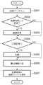
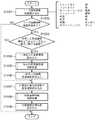
図2は本実施形態であるデジタルスチルカメラの画像データを記録媒体111に保存の工程を示すフローチャートである。この処理は、操作部112におけるシャッターボタンが押下された際の処理でもある。 FIG. 2 is a flowchart showing a process of storing image data of the digital still camera according to the present embodiment in the
ステップS201では、CCD103からのアナログ信号をA/D変換器103でデジタルデータに変換したデジタル画像データを内部メモリ107に格納する。このA/D変換器103は、後述する内部の画像処理の精度を高めるため、及び、後述する現状処理で熟練ユーザの要望に応えるため1画素を構成する各コンポーネントを8ビットを超えるビット数のデジタルデータに変換する(例えば12ビット)。 In step S <b> 201, digital image data obtained by converting the analog signal from the
ステップS202では、画像処理を行なうか否かのの判定を行う。この判定は、撮影時に撮影者が操作部112で設定した記録モードに従って従って行なう。記録モードには、RAW画像記録モードと通常記録モードがあり、後者に対しては記録画像のサイズ、画質、シャープネスや明るさ補正等が存在する。また、いずれの場合にも圧縮,非圧縮の設定も行なえる。RAW画像記録モードで圧縮するように設定されている場合には可逆圧縮(TIFF形式等のハフマン符号化等)を行なう。また、通常記録モードで圧縮するように設定されている場合にはの場合にはJPEGBaseline符号化(非可逆圧縮)が行われる。 In step S202, it is determined whether to perform image processing. This determination is performed in accordance with the recording mode set by the photographer using the
さて、ステップS202で通常記録モードが指示されていると判断した場合には、ステップS203に進み、操作部112で設定された条件に従って画像処理が行われる。本実施形態ではフィルタ処理やホワイトバランスやオートフォーカス等の情報に基づいた色調整などの処理を行なう。この段階で、画素を構成する各コンポーネントは8ビットに丸め込まれる。 If it is determined in step S202 that the normal recording mode is instructed, the process proceeds to step S203, and image processing is performed according to the conditions set by the
ステップS204では、圧縮記録であるか否かの判定を行う。この判定は、操作部112で設定した圧縮の要否に基づき判定する。 In step S204, it is determined whether or not the compressed recording is performed. This determination is made based on the necessity of compression set by the
圧縮すると判定した場合には、ステップS205に進む。RAW画像記録モードの場合には、内部メモリ107に格納されたRAW画像データを可逆圧縮符号化する。すなわち、A/D変換器104で得られた各コンポーネントが12ビットのまま可逆符号化を行なう。また、通常記録モードの場合にはJPEG Baseline符号化(非可逆)を行なう。JPEG Baseline符号化は、各画素のコンポーネントは8ビットで表現される。 If it is determined to compress, the process proceeds to step S205. In the case of the RAW image recording mode, the RAW image data stored in the
この後、ステップS206に進んで、撮影日時、撮影機種、フラッシュオン/オフ、撮像画像ファイルの記録形式などの撮影条件や記録条件から属性情報を生成し、それを付加する。そして、ステップS207で、記録媒体111にファイルとして書き込む。 Thereafter, the process proceeds to step S206, where attribute information is generated from the shooting conditions and recording conditions such as the shooting date and time, the shooting model, flash on / off, and the recording format of the captured image file, and added. In step S207, the file is written in the
なお、記録媒体111には圧縮されたファイル、非圧縮ファイルが存在し得るが、CCD103から出力された信号をA/D変換し、ホワイトバランス処理以降の色に関する画像処理を施していない段階の画像(各コンポーネントが12ビット)にまで戻すことができる画像データファイルをRAW画像データと呼ぶ。A compressed file and an uncompressed file may exist in the
なお、撮像センサから得られた、A/D変換を施した画像信号に輝度信号と色信号に分ける色分離処理をしていない段階の画像データ、あるいは、複数色から成る色フィルタをもった単板センサからの出力信号を色補間処理する前の段階の画像データをRAW画像データとしても良い。また、複色感光層を持った撮像センサのカラープレーンデータ生成処理をする前の画像データでも良い。 It should be noted that the image signal obtained from the image sensor is subjected to A / D conversion and is not subjected to color separation processing for separating the luminance signal and the color signal, or a single color filter having a plurality of colors. The image data at the stage before the color interpolation processing of the output signal from the plate sensor may be RAW image data. Further, it may be image data before color plane data generation processing of an imaging sensor having a multicolor photosensitive layer.
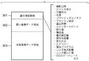
図3は記録媒体111に格納された画像ファイルの構造を示している。 FIG. 3 shows the structure of the image file stored in the
図3において、301は画像属性情報領域であり、画像データサイズ、撮影日時、撮影機種、圧縮方法、フラッシュオン/オフ、など撮影時の情報および画像の読み出しや再生、選択に必要な情報を記憶する領域である。302は縮小画像データ領域で、画像ファイルの一覧表示の際に利用する縮小画像データを記憶する領域である。303は画像データ領域であり、当該画像ファイルとして格納すべき全ての画像データを記憶する領域である。 In FIG. 3,
図4(a)乃至(c)は、本実施形態であるCCD103の光電変換素子の配列を示している。この配列は、一般にBeyar配列と呼ばれるものである。A/D変換器104によってデジタル化されて保存されたデータは、各原色フィルタで且つ単色感光層の場合、図4(a)のようなブロックに分割される。ただし1つのブロックは図4(b)のように色信号赤、青、緑(RGB)を含む4つのコンポーネントで構成され、1ブロックが連続的に繰り返されることで、同図(a)のような配列を形成している。実施形態におけるRAW画像データは、コンポーネントが12ビットで表わされるデータを意味する。 4A to 4C show the arrangement of photoelectric conversion elements of the
また、通常のカラー画像の1画素のように、R、G、Bの3つのコンポーネントのデータを生成する場合(JPEG符号化を行なう場合)には、各R、G、Bのデータは以下のようにして算出される。 In addition, when data of three components R, G, and B is generated (when JPEG encoding is performed) like one pixel of a normal color image, the data of each R, G, and B is as follows: In this way, it is calculated.
今、注目している位置(x、y)が図4(c)のように、原色フィルタRの位置にあるものとする。位置(x、y)には、R成分のデータは存在するが、B、Gの成分は存在しない。そこで、次のようにしてR、G、Bのデータを求める。但し、以下の式でD(x、y)は、RAW画像データの座標(x,y)の値であるものとする。
R(x,y) = D(x,y)
G(x,y) ={D(x+1,y)+D(x-1,y)+D(x,y+1)+D(x,y-1)}/4
B(x,y) ={D(x+1,y-1)+D(x-1,y+1)+D(x+1,y+1)+D(x-1,y-1)}/4 …式1Assume that the position (x, y) of interest is at the position of the primary color filter R as shown in FIG. At position (x, y), R component data exists, but B and G components do not exist. Therefore, R, G, and B data are obtained as follows. In the following expression, D (x, y) is assumed to be the value of the coordinates (x, y) of the RAW image data.
R (x, y) = D (x, y)
G (x, y) = {D (x + 1, y) + D (x-1, y) + D (x, y + 1) + D (x, y-1)} / 4
B (x, y) = {D (x + 1, y-1) + D (x-1, y + 1) + D (x + 1, y + 1) + D (x-1, y-1 )} / 4 ... Formula 1
上記は、注目座標位置はR原色フィルタが存在する場合であるが、注目画素位置がGまたはB原色フィルタの場合にも同様にして求めることになる。但し、G成分を注目した場合、その位置に隣接するBデータ、Rデータはそれぞれ2つ組しか存在しないので、上記式は多少変更されることになる。 The above is the case where the target coordinate position is the case where the R primary color filter exists, but the same is obtained when the target pixel position is the G or B primary color filter. However, when attention is paid to the G component, there are only two sets of B data and R data adjacent to the position, so the above formula is slightly changed.
次に、記録媒体111に記録された画像ファイル中のRAW画像データファイルをパーソナルコンピュータ等の汎用情報処理装置(以下、PCという)で読出し、同装置上で実行するアプリケーションプロでもって現像及び編集処理する場合について説明する。 Next, a RAW image data file in the image file recorded on the
図11は実施形態におけるPCのブロック構成図である。図示において、1はPC本体であり、2は装置全体の制御を司るCPU、3はBIOSやブートプログラムを記憶しているROM、4はRAMである。5はキーボード(KB)、マウス等のポインティングデバイス(PD)である。6は表示制御部であり、内部にはビデオメモリが設けられている。7は表示制御部から出力されたビデオ信号を表示する表示装置(CRTやLCDディスプレイ等)である。9はデジタルカメラから抜き出したメモリカード等の記憶媒体をアクセスするカードリーダ、10はデジタルカメラ20(図1参照)のインタフェース110と接続するインタフェースである。 FIG. 11 is a block diagram of a PC in the embodiment. In the figure, 1 is a PC main body, 2 is a CPU that controls the entire apparatus, 3 is a ROM that stores a BIOS and a boot program, and 4 is a RAM.
上記構成において、電源が投入されると、CPU2はROM3のブートプログラムに従って、ハードディスク8よりOSをRAM4にロードし、ユーザの指示に応じて本実施形態にかかる画像編集アプリケーションプログラムもRAM4にロードされることで、本装置が画像処理装置として機能することになる。実施形態のアプリケーションが起動した際には、図11に示すように、画像ファイルを読込んだり、各種変数を確保する作業領域、並びに、キャッシュ領域が確保されることになる。 In the above configuration, when the power is turned on, the
図12は、実施形態の画像編集アプリケーションプログラムが起動した際の、画像編集にかかるGUIを示している。図示の様に、本実施形態における編集プログラムを実行すると、表示画面には、2つのウインドウ40、45が表示される。 FIG. 12 shows a GUI for image editing when the image editing application program of the embodiment is started. As illustrated, when the editing program according to the present embodiment is executed, two
ウインドウ40は主に編集中の画像を表示するものであり、現像処理もしくは編集結果の画像を表示する画像表示エリア43、画像表示エリア43のサイズを指定する表示サイズ指示部41、表示倍率を指示する倍率指示部50、編集結果を保存する保存ボタン42、更には、画像ファイルを読込むためのダイアログボックス(不図示)を表示させるための「ファイル」ボタン44が設けられている。表示サイズ指示部41の右端には、上下の矢印が表示され、ここをマウスに連動するカーソルを移動してクリック操作(以下、単に操作という)することで、画像表示エリア43のサイズを変更することができる。倍率指示部50の操作も同様である。画像表示エリア43の大きさは、ウインドウ40を越える設定も可能である。ウインドウ40そのものを変更する場合には、ウインドウ40の右下部分52をドラッグ操作することで変更可能である。 The
ここで倍率指示部50で指示される倍率であるが、倍率100%とは、原画像(RAW画像)の1画素が画像表示エリア43の1画素に対応することを意味する。従って図示の「20%」とは、原画像を5×5画素が、1表示画素に対応することを意味する。すなわち、水平、垂直とも1/5倍になることを意味する。 Here, the magnification is designated by the
なお、画像表示エリア43に、原画像の一部分を表示している場合には、画像表示エリア43内でスクロールさせて別な位置の画像を見ることができる。画像表示エリア43内での画像のスクロールは、マウスカーソル(不図示)を画像表示エリア43内に移動し、ドラッグ操作(ボタンを押下しながらマウスを移動する操作)を行なうものとするが、別途垂直、水平スクロールバーを用意し、それを操作することで実現しても構わない。 If a part of the original image is displayed in the
一方、ウインドウ45であるが、ここには、各種画像編集項目が表示され、利用者はそのうちの所望とする項目のスライダーのツマミ(図示では弱、中、強の3段階としたが、勿論、これ以上の多段階でも良い)を移動することで、該当する編集項目を調整することが可能となっている。図示では、編集項目としてコントラストコントロール46、色の濃さコントロール47、シャープネスコントロール48の3つが表示されているが、スクロールバー49を操作してスクロールすることで、他の設定項目(トーンカーブ、明るさ、ホワイトバランス設定値、色温度、色相など)の項目を表示させることができる。本実施形態のアプリケーションを起動した直後の状態(デフォルト)では、各編集項目のスライダーバーのツマミ位置は、該当する画像の撮影時の設定情報によって決定される。すなわち、画像ファイルを読込んだ際、その属性情報301から各パラメータを抽出し、それに基づいて各編集項目のスライダーバーのツマミ位置を決定するようにした。なお、属性情報301中に、該当する設定情報が存在しない場合には、該当する編集項目のスライダーバーのツマミ位置は、中央になるように設定する。 On the other hand, in the
なお、以下の説明において、各編集項目毎のスライダーバーのツマミ位置で決定される状態値を編集パラメータ(もしくは単にパラメータ)と呼び、ツマミ位置を変更して、その編集項目の状態を変更する操作ことを「パラメータを設定する」と言う。また、編集の度合を設定する場合、図示のようにスライダーバーを用いると操作性が良いが、数値入力によって行ってもよいし、その設定のための表示形態は如何なるものでも構わない。また、ウインドウ40、45の2つを表示するものとしたが、1つのウインドウに表示しても構わない。 In the following description, the state value determined by the slider bar knob position for each editing item is called an editing parameter (or simply parameter), and the operation of changing the knob position to change the state of the editing item. This is called “setting parameters”. Also, when setting the degree of editing, use of a slider bar as shown in the figure provides good operability, but it may be performed by numerical input, and any display form for setting may be used. Moreover, although two
以下、実施形態におけるアプリケーションプログラムにおける画像表示エリア43に表示する処理を図5のフローチャートに従って説明する。なお、ユーザはカードリーダ9やインタフェース10を介してデジタルカメラで撮像した画像ファイルを予めハードディスク8に格納しているものとする。 Hereinafter, the process of displaying in the
また、周知の通り、昨今のデジタルカメラのCCD103で得られる画素数は増える一方で、PCの表示装置7に表示可能な画素数よりも遥かに多くなってきている。更に、GUIのOSに限ってみても、アプリケーションで利用できるウインドウサイズは、必然的に表示装置の表示領域よりも小さく、撮像された画像データの1画素を表示装置で表示する1画素に対応させて(倍率100%)、尚且つ、画像全体を一度に表示することはできない。従って、100%の倍率で表示する場合には撮像画像の一部分を画像表示エリア43内に表示するしかない。また、撮像した画像全体を表示するためには、倍率を20%(0.2倍)等にして、撮像画像の複数画素を1表示画素に対応させる、或いは、適当な間隔で間引きして表示するしかない。本実施形態における画像編集アプリケーションはかかる点に着目し、画像編集処理を行なう。 As is well known, while the number of pixels obtained by the
先ず、ステップS501で、例えば、入力手段として、パーソナルコンピュータのハードディスク(もしくはカードリーダ9、インタフェース10を介してでも構わない)からRAW画像ファイルをRAM4に読み込む。 First, in step S501, for example, a RAW image file is read into the
ステップS502で、読込まれた属性情報301を読み込む。この属性情報とは、RAW画像の撮影時に決定される撮像条件であって、例えばビットの深さ(実施形態では12ビット)、圧縮形式、露出時間、シャッタースピード、絞り値、輝度値、露光補正値、レンズ最小F値、被写体距離、測光方式、光源、フラッシュオン/オフ、レンズ焦点距離、Fナンバー、露出プログラム、ISOスピードレート、フラッシュ強度などである。 In step S502, the
ステップS503では、属性情報を解析し、圧縮されているか否かの判定を行う。圧縮されていた場合、ステップS504で、属性情報で示される圧縮形式に基づき解凍処理(復号処理)を行う。この結果、非圧縮のRAW画像データを得ることができるが、この時点では各コンポーネントは12ビットで表現されていることに注意されたい。 In step S503, the attribute information is analyzed to determine whether or not compression has been performed. If it has been compressed, in step S504, decompression processing (decoding processing) is performed based on the compression format indicated by the attribute information. As a result, uncompressed RAW image data can be obtained, but it should be noted that at this point, each component is represented by 12 bits.
ステップS505で、色補間処理を行う。RAW画像は図4Bに示したブロック単位のデータで構成される。そのため、色補間処理を行う。この補間処理とは、例えば線形補間であるため、先に示した式1でR、G、Bデータを生成する。 In step S505, color interpolation processing is performed. The RAW image is composed of block unit data shown in FIG. 4B. Therefore, color interpolation processing is performed. Since this interpolation processing is, for example, linear interpolation, R, G, and B data are generated according to Equation 1 shown above.
次いで、ステップS506で、パーソナルコンピュータにおいてユーザが画質調整のために情報の設定をしたか否かの判定を行なわれる(以降、この設定情報をユーザー画質調整情報という)。ユーザー画質調整情報とは、例えば、シャープネス、コントラスト、カラーマトリックス、トーンカーブ、明度、彩度、色相、ホワイトバランスなどであり、キーボードやポインティングデバイスで設定され、一時的にRAM4に格納されるものである。 In step S506, it is determined whether or not the user has set information for image quality adjustment in the personal computer (hereinafter, this setting information is referred to as user image quality adjustment information). The user image quality adjustment information is, for example, sharpness, contrast, color matrix, tone curve, brightness, saturation, hue, white balance, etc., and is set by a keyboard or pointing device and temporarily stored in the
ユーザー画質調整情報が設定された場合、ステップS507で、そのユーザー画質調整情報をRAM4から読み込む。 When the user image quality adjustment information is set, the user image quality adjustment information is read from the
そして、ステップS508において、先のステップS502で読み込んだ属性情報およびステップS507で読み込んだユーザ画質調整情報を併せてRAW画像を再生するための再生パラメータを生成し、この再生パラメータに基づいたホワイトバランス処理を行う。ホワイトバランス処理に必要な属性情報とは、例えば光源情報、フラッシュオン/オフやフラッシュ強度などである。 In step S508, a reproduction parameter for reproducing the RAW image is generated by combining the attribute information read in step S502 and the user image quality adjustment information read in step S507, and white balance processing based on the reproduction parameter is performed. I do. The attribute information necessary for the white balance processing is, for example, light source information, flash on / off, flash intensity, and the like.
ステップS509では、R、G、Bの原色データ(R,G,B)を、輝度色差データ(Y,Cb,Cr)に変換する。 In step S509, R, G, B primary color data (R, G, B) is converted into luminance color difference data (Y, Cb, Cr).
ステップS510では、先のステップS502で読み込んだ属性情報および/または、ステップS507で読み込んだユーザー画質調整情報に基づいた、輝度調整処理を行う。輝度調整処理に必要な属性情報には、例えば露出時間、シャッタースピード、絞り値、輝度値、露光補正値、被写体距離、測光方式、Fナンバー、露出プログラムなどがある。 In step S510, luminance adjustment processing is performed based on the attribute information read in step S502 and / or the user image quality adjustment information read in step S507. The attribute information necessary for the brightness adjustment processing includes, for example, exposure time, shutter speed, aperture value, brightness value, exposure correction value, subject distance, photometry method, F number, and exposure program.
ステップS511では、先のステップS502で読み込んだ属性情報および/またはステップS507で読み込んだユーザー画質調整情報に基づいた、色調整処理を行う。 In step S511, color adjustment processing is performed based on the attribute information read in step S502 and / or the user image quality adjustment information read in step S507.
ステップS512では、ステップS502で読み込んだ属性情報および/またはステップS507で読み込んだユーザー画質調整情報に基づいた、シャープネス調整処理を行う。シャープネス処理に必要な属性情報には、例えば露出時間、シャッタースピード、絞り値、輝度値、露光補正値、被写体距離、測光方式、Fナンバー、露出プログラム、レンズの歪み情報、レンズ焦点距離、レンズ最小F値やISOスピードレートや絞り値などがある。 In step S512, sharpness adjustment processing is performed based on the attribute information read in step S502 and / or the user image quality adjustment information read in step S507. The attribute information necessary for sharpness processing includes, for example, exposure time, shutter speed, aperture value, brightness value, exposure correction value, subject distance, metering method, F number, exposure program, lens distortion information, lens focal length, and lens minimum. There are F value, ISO speed rate, aperture value, etc.
次いで、ステップS513で、輝度色差データ(Y,Cb,Cr)を、原色データ(R、G、B)に変換し、表示するために各コンポーネントを8ビットに丸めるよりを行なう。換言すれば、ステップS505乃至S513までの演算精度は12ビットで行なうため、演算誤差を最小限なものとすることができることになる。 In step S513, the luminance color difference data (Y, Cb, Cr) is converted into primary color data (R, G, B) and each component is rounded to 8 bits for display. In other words, since the calculation accuracy from step S505 to S513 is performed with 12 bits, the calculation error can be minimized.
そして、ステップS514で、表示装置7に出力する。表示装置7は、CRTディスプレイや液晶ディスプレイ等で良い。 And it outputs to the
ステップS508からS513の処理は1画素ずつの処理であるため、同処理に要する時間は画素数に比例する。なお、本実施形態では、ステップS507のRAW画像の色補間処理後のステップS508のホワイトバランス処理からステップS513のRGBデータに変換するまでの処理を、これ以降は現像処理という。 Since the processing from step S508 to S513 is processing for each pixel, the time required for the processing is proportional to the number of pixels. In the present embodiment, the processing from the white balance processing in step S508 after the color interpolation processing of the RAW image in step S507 to the conversion to RGB data in step S513 is hereinafter referred to as development processing.
本実施形態では、原色フィルタで且つ単色感光層の場合の処理を例に説明したが、撮像センサフィルタ特性によって異なる場合がある。例えば、色信号シアン・マゼンタ・イエロー(CMY)で構成される補色フィルタの場合や、複数色の画素配列の並び順が異なる場合、画素の形は縦横比が1:1ではない(2:1など)。それぞれの場合には、ステップS505以降の処理がそれぞれの撮像センサのフィルタ特性に対応していればよい。 In the present embodiment, the processing in the case of a primary color filter and a monochromatic photosensitive layer has been described as an example. However, the processing may differ depending on the imaging sensor filter characteristics. For example, in the case of a complementary color filter composed of color signals cyan, magenta, and yellow (CMY), or when the arrangement order of a plurality of color pixel arrays is different, the aspect ratio of the pixel is not 1: 1 (2: 1). Such). In each case, it is only necessary that the processing after step S505 corresponds to the filter characteristics of each imaging sensor.
次に、表示装置における画像表示エリア43のサイズ及び表示倍率と、原画像サイズとの対応関係について説明する。 Next, the correspondence relationship between the size and display magnification of the
図6(a)乃至(c)は本実施形態におけるPCにおける倍率毎の出力結果の例である。 FIGS. 6A to 6C are examples of output results for each magnification in the PC in this embodiment.
図6(a)RAW画像全体に対して等倍、つまり倍率が100%表示の出力結果だとすると、図6(b)は50%、図6(c)は25%の倍率の表示出力結果である。倍率50%表示画像の縦横のそれぞれの画素数は、100%表示画像に対して1/2である。全体の画素数(面積)は100%表示画像に対して1/2の二乗、すなわち1/4である。25%表示画像の縦横の画素数は、100%表示画像に対して1/4である。全体の画素数(面積)は100%表示画像に対して1/4の二乗、すなわち1/16である。つまり、倍率100%表示画像に対して倍率n%表示の縦横それぞれの画素数は、n/100で、全体の画素数(面積)は、n/100の二乗となる。 6A, assuming that the output result is the same magnification of the entire RAW image, that is, the magnification is 100%, FIG. 6B is the display output result of 50%, and FIG. 6C is the display output result of 25%. . The number of pixels in the vertical and horizontal directions of the 50% magnification display image is ½ that of the 100% display image. The total number of pixels (area) is ½ of the square of the 100% display image, that is, ¼. The number of vertical and horizontal pixels of the 25% display image is ¼ that of the 100% display image. The total number of pixels (area) is 1/4 square of the 100% display image, that is, 1/16. That is, the number of vertical and horizontal pixels for n% magnification display with respect to a 100% magnification display image is n / 100, and the total number of pixels (area) is n / 100 squared.
ここで、本実施形態の対象画像抽出処理のRAW画像全体を倍率n%した場合の間引き処理について説明する。 Here, the thinning process when the entire RAW image of the target image extraction process of the present embodiment is scaled by n% will be described.
横方向の画素数(x)と縦方向の画素数(y)の画像について、n/100(nは100以下の正の整数)にするには、横方向の画素数を(x×(100-n)/100)画素を間引き、縦方向の画素数を(y×(100-n)/100)画素を間引く。間引く方法は例えば、(n/100)を約分して( i / k )で表し、k 画素中から等間隔になるように i 個の画素を間引く。約分できない場合や等間隔にできない場合は、結果的に横方向の画素数が(x×n/100)縦方向の画素数が(y×n/100)になるように、且つ処理が少なく画質が一番望ましくなるような方法を用いればよい。このように、対象画像抽出処理が行われる。 In order to obtain an image having a horizontal pixel count (x) and a vertical pixel count (y) of n / 100 (n is a positive integer of 100 or less), the horizontal pixel count is (x × (100 -n) / 100) pixels are thinned out, and the number of pixels in the vertical direction is thinned out (y × (100-n) / 100) pixels. As a thinning method, for example, (n / 100) is divided and expressed as (i / k), and i pixels are thinned out at equal intervals from k pixels. If it cannot be reduced or evenly spaced, as a result, the number of pixels in the horizontal direction is (x × n / 100) and the number of pixels in the vertical direction is (y × n / 100), and the processing is small. A method that provides the most desirable image quality may be used. In this way, the target image extraction process is performed.
間引き処理前もしくは間引き処理中もしくは間引き処理後、スムージング処理を行うと更に望ましい縮小出力結果を得られる可能性がある。スムージング処理は、間引きをした画像に対して滑らかに見えるように平滑化を行なう画像処理であって、例えば、原画像( x , y )座標の位置およびその周辺の画素から、画像表示エリア43中の出力画素情報Out( x , y )は次式2で算出される。
Out(x,y)
= {In(x,y)×2 + In(x-1,y) + In(x+1,y)+ In(x,y-1) + In(x,y+1)}÷6 …(式2)If the smoothing process is performed before the thinning process, during the thinning process, or after the thinning process, a more desirable reduced output result may be obtained. The smoothing process is an image process for performing smoothing so that the thinned image looks smooth. For example, from the position of the original image (x, y) coordinates and surrounding pixels, the smoothing process is performed in the
Out (x, y)
= {In (x, y) × 2 + In (x-1, y) + In (x + 1, y) + In (x, y-1) + In (x, y + 1)} ÷ 6… (Formula 2)
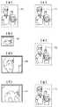
図7(a)乃至(g)は本実施形態である画像処理装置において設定された画像表示エリア43のサイズにおける出力結果を示している。 FIGS. 7A to 7G show output results in the size of the
例えば、図7(a)の点線枠内が原画像の全体を示している。画像表示エリア43のサイズが図7(b)の状態で、且つ、倍率が100%となっている場合には、図7(c)の枠71内の画像を表示することになる。 For example, the dotted line frame in FIG. 7A shows the entire original image. When the size of the
より詳しく説明すると次の通りである。なお、以下の説明での座標の単位はpixelである。 More detailed description is as follows. In the following description, the unit of coordinates is pixel.
原画像70の左上隅の座標を(0、0)、右下隅の座標を(1536、2048)とする。また、画像表示エリア43のサイズが表1で示されるサイズとする。そして、原画像中の座標(250、300)を、画像表示エリア43の左上隅位置に対応させ、倍率100%で表示する場合を考察する。この場合の画像表示エリア43内の右下隅に表示するべき原画像中の画素位置(x1,y1)は式3で与えられる。 The coordinates of the upper left corner of the

y1 = 300 + (320 × 100 ÷ 100) − 1 …(式3)
y1 = 300 + (320 × 100 ÷ 100) −1 (Formula 3)
また、同じ倍率で、画像表示エリア43のサイズが図7(b)から図7(d)のように大きくした場合には、図7(e)の実線枠72内の画像情報を表示することになる。 When the size of the
具体的には、画像表示エリア43のサイズが表2に示すサイズになった場合で、原画像の座標の(80,120)の画素が画像表示エリア43の左上隅に表示される場合、画像表示エリアの右下隅の座標(x1、y1)に表示すべき原画像の座標は式4で得られる。 Specifically, when the size of the
y1 = 120 + (560 × 100 ÷ 100) − 1 …(式4)
y1 = 120 + (560 × 100 ÷ 100) −1 (Formula 4)
また、画像表示エリア43のサイズが図7(d)と同じであり、倍率を200%にした場合には、図7(g)の実線枠73の画像が、図7(f)のように表示される。 When the size of the
具体的には、原画像の座標の(80,120)の画素が画像表示エリア43の左上隅に表示される場合、画像表示エリアの右下隅の座標(x1、y1)に表示すべき原画像の座標は式5で得られる。 Specifically, when (80, 120) pixels of the coordinates of the original image are displayed at the upper left corner of the
具体的には、画像表示エリア43のサイズが表3に示すサイズであり、原画像の座標の(80,120)の画素が画像表示エリア43の左上隅に表示される場合、画像表示エリアの右下隅の座標(x1、y1)に表示すべき原画像の座標は式5で得られる。 Specifically, when the size of the
y1 = 120 + (560 × 100 ÷ 200) − 1 …(式5)
y1 = 120 + (560 × 100 ÷ 200) −1 (Formula 5)
上記の処理をまとめると、次のようになる。今、画像表示エリア43のサイズが表4に示すようになっていて、倍率(百分率で示される整数)をMとし、画像表示エリア43の左上隅に表示する原画像の座標を(x0、y0)とすると、画像表示エリア43の右下隅に表示されるべき原画像中の座標(x1、y1)は式6で得られる。 The above processing is summarized as follows. Now, the size of the
y1 = y0 + (Window_H × 100 ÷ M) − 1 …(式6)
y1 = y0 + (Window_H × 100 ÷ M) −1 (Formula 6)
以上からもわかるように、画像表示エリア43のサイズWindow_W、高さWindow_Hと、その際の倍率M、更には、画像表示エリア43の左上隅位置に表示すべき原画像の画素位置(x0,y0)が与えられると、原画像からの切り出し範囲(枠71乃至73の位置とサイズ)が決定されることになる。 As can be seen from the above, the size Window_W and the height Window_H of the
従って、現像結果を保存する場合には原画像全体に対して行なうことが必要であるものの、編集中の現像処理は、原画像の切り出し範囲内の部分的な領域に対して行なえば良いことになり、高いレスポンスを得ることができる。 Accordingly, when saving the development result, it is necessary to perform the entire original image, but the development process during editing may be performed on a partial area within the cutout range of the original image. Thus, a high response can be obtained.
図8は、現像処理の前段階で行われる画像の切り出し処理(以下、対象画像抽出処理という)を示すフローチャートである。以降、ステップS801〜S807の処理を対象画像抽出処理と記す。 FIG. 8 is a flowchart showing an image cut-out process (hereinafter referred to as a target image extraction process) performed at a stage prior to the development process. Hereinafter, the processing in steps S801 to S807 is referred to as target image extraction processing.
以下、図8のフローチャートに従って説明するが、説明中の各変数は以下の意味である。
fulpix_w :RAW画像の水平方向の画素数、
fulpix_h :RAW画像の垂直方向の画素数、
window_w :画像表示エリア43の水平方向の画素数、
window_h :画像表示エリア43の垂直方向の画素数、
M :倍率指示部50で指定された倍率(%)、
C_w :倍率Mに基づく原画像の水平方向の画素数、
C_h :原画Mに基づく原画像の垂直方向の画素数Hereinafter, although it demonstrates according to the flowchart of FIG. 8, each variable in description has the following meaning.
fulpix_w: Number of pixels in the horizontal direction of the RAW image
fulpix_h: Number of pixels in the vertical direction of the RAW image,
window_w: the number of pixels in the horizontal direction of the
window_h: number of pixels in the vertical direction of the
M: Magnification (%) specified in the
C_w: the number of pixels in the horizontal direction of the original image based on the magnification M,
C_h: Number of pixels in the vertical direction of the original image based on the original image M
ステップS801では、RAW画像から処理対象となる画像全体の画像情報を読込む。 In step S801, image information of the entire image to be processed is read from the RAW image.
次いで、ステップS802で、表示に関する情報を読込む。表示に関する情報とは、モニタ上表示された画像表示エリア43のサイズ情報window_w、window_h、及び、拡大率情報Mである。 In step S802, information related to display is read. The information related to display is size information window_w, window_h, and enlargement rate information M of the
ステップS803では、倍率に基づくRAW画素のサイズC_w、C_hを次式7で算出する。
C_w = ( fulpix_w × M ÷100)
C_h = ( fulpix_h × M ÷100) …(式7)In step S803, the RAW pixel sizes C_w and C_h based on the magnification are calculated by the following equation (7).
C_w = (fulpix_w × M ÷ 100)
C_h = (fulpix_h × M ÷ 100) (Equation 7)
ステップS804では、画像表示エリア43のサイズwindow_w、window_hと、倍率Mを反映させたRAW画像のサイズC_w、C_hを比較する。具体的には、次式(8)、(9)が真となるかどうかを判定する。
window_w < C_w …(式8)
window_h < C_h …(式9)In step S804, the sizes window_w and window_h of the
window_w <C_w (Formula 8)
window_h <C_h (Formula 9)
ステップS804で、式(8)、(9)が満たされる場合、RAW画像全体を表示することができないことを意味する。つまり、RAW画像全体の一部分の表示になる。それ故、ステップS805では、部分的に切り出すための切り出し領域のサイズと位置を算出する。この切り出し領域のサイズは、先に示した式6で求めればよい。なお、式(6)において、座標(x0,y0)であるが、RAW画像データを最初に現像処理する場合には、画像表示エリア43の中心位置と、RAW画像データの中心位置とを一致させるよう場合には、
x0=fulpix_w/2−window_w/2
y0=fulpix_h/2−window_h/2
として求めれば良い。If the expressions (8) and (9) are satisfied in step S804, it means that the entire RAW image cannot be displayed. That is, a part of the entire RAW image is displayed. Therefore, in step S805, the size and position of the cutout area for partial cutout are calculated. What is necessary is just to obtain | require the size of this cutout area | region by
x0 = fulpix_w / 2-window_w / 2
y0 = fulpix_h / 2-window_h / 2
As long as you ask.
また、ステップS804で、式(8)、式(9)が満たさない場合には、倍率Mに応じた画像全体のサイズ(幅、高さ)が、画像表示エリア43のサイズ内に収まり、RAW画像全体が表示されることになるので、ステップS806に進む。 If the expressions (8) and (9) are not satisfied in step S804, the size (width and height) of the entire image corresponding to the magnification M is within the size of the
ステップS806で、倍率Mが100%(元のRAW画像の大きさ)より小さいか否か、すなわち、「M<100」を満たすか否かを判定する。倍率Mが100%より小さい場合は、画像全体に対して縮小画像になっているのでステップS807で、RAW画像データ中の切り出し領域内の画像データを「M/100」に従って間引き処理し、その結果を本実施形態における「対象画像抽出処理」の処理結果として出力する。間引き方法の例は図6(a)乃至(c)の説明の通りである。また、倍率Mが100%(RAW画像の1画素=1表示画素)以上であった場合に、間引き処理は行なわず、ステップS805で決定した切り出し領域内の画像データを、「対象画像抽出処理」の結果として出力する。 In step S806, it is determined whether or not the magnification M is smaller than 100% (the size of the original RAW image), that is, whether or not “M <100” is satisfied. If the magnification M is smaller than 100%, the entire image is a reduced image. In step S807, the image data in the cutout area in the RAW image data is thinned out according to “M / 100”, and the result Are output as the processing result of the “target image extraction processing” in the present embodiment. An example of the thinning-out method is as described with reference to FIGS. Further, when the magnification M is 100% (1 pixel of the RAW image = 1 display pixel) or more, the thinning process is not performed, and the image data in the cutout area determined in step S805 is “target image extraction process”. Is output as the result of.
以上のようにして、RAW画像データ中の切り出し領域からの画像データの抽出処理を行なうが、この抽出された画像データに対して、図5のステップS508〜S513の現像処理が行われる。このように表示状態に応じた抽出処理が行われることによって現像(再生)処理が行われる対象となる画像は、画像表示エリア43のサイズと設定された倍率によって決まるRAW画像の一部分にすることが可能となり、結果的に現像処理を行なう際の画素数は少なくできるので、現像処理に要する処理時間を削減することができる。 As described above, the image data is extracted from the cut-out area in the RAW image data. The development processing in steps S508 to S513 in FIG. 5 is performed on the extracted image data. Thus, by performing the extraction process according to the display state, the image to be subjected to the development (reproduction) process is made a part of the RAW image determined by the size of the
また、ステップS505の色補間を終えたRAW画像をキャッシュメモリ等に保持するようにしても良い。この場合には、色補間処理にかかる時間を削減出来るのでさらに高速化することが出来る。 Further, the RAW image after the color interpolation in step S505 may be held in a cache memory or the like. In this case, since the time required for the color interpolation process can be reduced, the speed can be further increased.
次に、実施形態における対象画像抽出処理を行なった場合の現像処理時間が、従来の現像処理よりも短くできる点について説明する。先ず、説明するまでに、各変数を以下にように定義する。
bef_time : 従来の処理時間(すなわち全画像情報を現像処理した場合の処理時間)
aft_time : 本実施形態を利用した場合の処理時間
pre_time : S501〜S505,S506及びS507の処理にかかる時間
dev_time : 現像処理の1画素あたりの処理にかかる時間
out_time : S514の処理にかかる時間
ext_time : 対象画像抽出処理にかかる時間
outpix_w : 対象画像抽出処理後の横方向pixel数
outpix_h : 対象画像抽出処理後の縦方向pixel数
vis_width :倍率に応じた表示領域内の横方向pixel数
vis_height :倍率に応じた表示領域内の縦方向pixel数Next, the point that the development processing time when the target image extraction processing in the embodiment is performed can be made shorter than the conventional development processing will be described. First, before explaining, each variable is defined as follows.
bef_time: Conventional processing time (that is, processing time when all image information is developed)
aft_time: Processing time when using this embodiment
pre_time: Time required for the processing of S501 to S505, S506, and S507
dev_time: Time required for development processing per pixel
out_time: Time required for S514 processing
ext_time: Time required for target image extraction processing
outpix_w: Number of horizontal pixels after target image extraction processing
outpix_h: Number of vertical pixels after target image extraction processing
vis_width: Number of horizontal pixels in the display area according to the magnification
vis_height: Number of vertical pixels in the display area according to the magnification
従来の処理時間(bef_time)は次式10で表わされる。
bef_time = pre_time + dev_time ×(fulpix_w × fulpix_h) + out_time …(式10)
一方、本実施形態の対象画像抽出処理を行った場合の処理時間(aft_time)は次式11で示される。
aft_time = pre_time + ext_time + dev_time ×(outpix_w × outpix_h) + out_time …(式11)
上記の式(10)、式(11)で算出される時間は、乗算係数であるfulpix_w、fulpix_h、outpix_w、及び、outpix_hの値が支配的であることは明らかである。The conventional processing time (bef_time) is expressed by the following equation (10).
bef_time = pre_time + dev_time × (fulpix_w × fulpix_h) + out_time… (Formula 10)
On the other hand, the processing time (aft_time) when the target image extraction processing of the present embodiment is performed is expressed by the following equation 11.
aft_time = pre_time + ext_time + dev_time × (outpix_w × outpix_h) + out_time… (Formula 11)
It is clear that the times calculated by the above equations (10) and (11) are dominated by the values of the multiplication factors fulpix_w, fulpix_h, outpix_w, and outpix_h.
ここで、対象画像抽出処理後の画素数(outpix_w, outpix_h)の算出方法を以下に示す。尚、原画像の大きさ(fulpix_w, fulpix_h)と、表示に関する情報(M, window_w, window_h)は読み込み済み(代入済み)とする。 Here, a calculation method of the number of pixels (outpix_w, outpix_h) after the target image extraction processing is shown below. It is assumed that the size of the original image (fulpix_w, fulpix_h) and display information (M, window_w, window_h) have been read (assigned).
C_h = fulpix_w * M / 100;
C_w = fulpix_h * M / 100;
if(C_W > window_w){
vis_width = window_w;
}else{
vis_width = C_w;
}
if(C_h > window_h){
vis_height = window_h;
}else{
vis_height = C_h;
}
outpix_w = vis_width * 100 / M;
outpix_h = vis_height * 100 / M; …(式12)C_h = fulpix_w * M / 100;
C_w = fulpix_h * M / 100;
if (C_W> window_w) {
vis_width = window_w;
} else {
vis_width = C_w;
}
if (C_h> window_h) {
vis_height = window_h;
} else {
vis_height = C_h;
}
outpix_w = vis_width * 100 / M;
outpix_h = vis_height * 100 / M; ... (Formula 12)
ここで、本実施形態において、次式13は常に真である。
outpix_w×outpix_h <= fulpix_w× fulpix_h …(式13)
そのため、式14の条件が成り立つ場合、式15は真である。
ext_time < dev_time × (( fulpix_w × fulpix_h) - ( outpix_w × outpix_h) …(式14)
bef_time > aft_time …(式15)Here, in this embodiment, the following expression 13 is always true.
outpix_w × outpix_h <= fulpix_w × fulpix_h… (Formula 13)
Therefore, when the condition of Expression 14 is satisfied, Expression 15 is true.
ext_time <dev_time × ((fulpix_w × fulpix_h)-(outpix_w × outpix_h)… (Formula 14)
bef_time> aft_time (Formula 15)
本実施形態において属性情報は、ファイルに付属して記録されていることを例に挙げたが、画像情報と関連づけられて保存されていれば、別ファイルで記録されていても、保存されているメディアなどが違ったとしても画像処理装置が読み込める条件が整っていれば、可能である。 In this embodiment, the attribute information is recorded as an example attached to the file. However, if the attribute information is stored in association with the image information, the attribute information is stored even if it is recorded in another file. Even if the media is different, it is possible if the conditions that the image processing apparatus can read are in place.
本実施形態において使用者が画像表示エリア43と倍率Mを変更せず画質調整のみを行った場合(つまり、ユーザ画質調整情報のみ変更があった場合)、前回の対象画素抽出処理後の画像情報がキャッシュメモリなど記憶媒体に保持されていれば、前記対象画素抽出後の画像情報に対してS508〜S514の処理を行なえば更なる処理時間の短縮ができる。ただし、記憶媒体からの読み込み時間(read_time)が対象画像抽出処理までの時間(pre_time + ext_time)より短かいことが条件である。対象画像抽出処理後の画像情報に対して、ステップS508〜S514の処理を行った場合の処理時間(cash_time)を式16に示す。
cash_time = read_time + dev_time ×( outpix_w × outpix_h) + out_time …(式16)In the present embodiment, when the user performs only the image quality adjustment without changing the
cash_time = read_time + dev_time × (outpix_w × outpix_h) + out_time… (Formula 16)
そして、式17の条件が成り立つ場合、式18は真である。
read_time < pre_time + ext_time + dev_time × (( fulpix_w × fulpix_h) - ( outpix_w × outpix_h) …(式17)
bef_time > cash_time …(式18)If the condition of Expression 17 is satisfied, Expression 18 is true.
read_time <pre_time + ext_time + dev_time × ((fulpix_w × fulpix_h)-(outpix_w × outpix_h)… (Formula 17)
bef_time> cash_time (Formula 18)
本実施形態において、画像の再生および処理の対象となる範囲を算出して(ステップS805)から、間引き処理(ステップS807)を行ったが、間引き処理を行った後、前記範囲を算出しても同様の効果がある。 In this embodiment, the range to be subjected to image reproduction and processing is calculated (step S805) and then the thinning process (step S807) is performed. However, after the thinning process is performed, the range may be calculated. There is a similar effect.
また、色補間処理、間引き処理、表示領域の部分を抽出処理、いずれかの組み合わせで同時もしくは平行して行うことができる場合には、同時もしくは平行に処理を行ってもよい。また、色補間処理後の画像情報をキャッシュメモリ等に保持しておくことによって、対象画像抽出処理やそれ以降のユーザの設定した再生パラメータに基づく現像処理やスクロール等の表示がさらに高速になることは言うまでもない。 Further, when color interpolation processing, thinning processing, and display area portion extraction processing can be performed simultaneously or in parallel by any combination, the processing may be performed simultaneously or in parallel. In addition, by storing the image information after color interpolation processing in a cache memory or the like, the target image extraction processing and subsequent display such as development processing and scrolling based on playback parameters set by the user can be further accelerated. Needless to say.
また、本実施形態では、RAW画像の色補間処理後の画像に対して対象画像抽出処理を行なう場合について示した。一方、可逆圧縮したRAW画像の記録時に所定の画素数ごとにマーキング等のインデックス情報を挿入することによって、圧縮されたRAW画像から所定の画素位置が分かるようなRAW画像とすることもであれば、対象画像抽出処理は解凍処理前のステップS504の前に行なっても良い。つまり、RAW画像からの対象画像抽出処理を行なった後、抽出した範囲のみに対して解凍処理を行い、色補間とその後同様に現像処理を行なう。このように、抽出された対象画像のみに解凍処理を施すことによって、予め画像全体を解凍する必要がなくなるため、前述のpre_timeをさらに短くすることが可能になる。なお、この場合は対象画像抽出後の解凍処理と色補間処理は現像処理の前に行なうことになるが、全体を解凍するのに要する時間よりも短くなるため、現像処理後の画像を高速に表示することが可能となる。 Further, in the present embodiment, the case where the target image extraction process is performed on the image after the color interpolation process of the RAW image is shown. On the other hand, by inserting index information such as marking for each predetermined number of pixels when recording a reversibly compressed RAW image, it is possible to obtain a RAW image in which a predetermined pixel position is known from the compressed RAW image. The target image extraction process may be performed before step S504 before the decompression process. That is, after the target image extraction process from the RAW image is performed, the decompression process is performed only on the extracted range, and the color interpolation and the development process are performed in the same manner. In this way, by performing the decompression process only on the extracted target image, it is not necessary to decompress the entire image in advance, so that the aforementioned pre_time can be further shortened. In this case, the decompression process and the color interpolation process after the target image extraction are performed before the development process. However, since the time required for decompressing the entire image is shorter, the image after the development process is processed at high speed. It is possible to display.
本実施形態において、画像の再生および現像処理の対象となる範囲を算出する方法を式6に示したが、現像処理において式2のスムージング処理のように出力画素の周辺画素も必要となる場合には、前記範囲よりも横方向および縦方向に必要な画素分大きい範囲を対象画素として現像し、表示時に表示領域に該当する範囲のみ表示すればよい。 In this embodiment, the method for calculating the range to be subjected to image reproduction and development processing is shown in
本実施形態において、画像表示エリア43のサイズがRAW画像のサイズよりも小さく解像に関する画質確認に適さない場合、例えば100%以下の場合、現像処理は画質調整の指標として妥当な画質を保てるならば、高速化のために100%で用いる現像処理中の適当な処理を省略してもよい。例えば、倍率が25%などの場合、解像に関する画質確認の判断材料としにくいため、シャープネス処理を簡易なものにしてしまってもよいし、シャープネス処理のみの場合は処理結果を反映させずに、倍率に応じて抽出した画像の表示だけを行なっても良い。ここで、シャープネス処理とは、アパーチャ補正処理あるいはエッジ強調処理を意味する。 In the present embodiment, if the size of the
以上、第1の実施形態に示したように、例えば、任意の倍率や画像表示エリアのサイズ等の表示状態に応じて、処理する対象となる画像情報を変更することによって、従来より高速に現像処理結果の表示ができる。 As described above, as shown in the first embodiment, for example, by changing the image information to be processed according to the display state such as an arbitrary magnification and the size of the image display area, development is performed at a higher speed than in the past. Processing results can be displayed.
なお、上記のようにして最終的に現像処理結果に操作者が満足すると、操作者は保存ボタン42を操作することになる。この保存ボタン42が操作された場合には、図13に示す手順で、注目しているRAW画像データに対する編集結果をファイルとして保存することになる。 When the operator finally satisfies the development processing result as described above, the operator operates the
すなわち、ステップS1301でRAW画像データを読込む。そして、ステップS1302で、入力したRAW画像データを、保存ボタン42を操作する直前でウインドウ45で設定されたパラメータに従って、現像処理する。このときの現像処理では、倍率100%、画像表示エリア43のサイズがRAW画像のサイズと同じであるものとして、処理を行なえば良い。そして、ステップS1303にて、処理した結果をハードディスク装置8等にファイルとして保存する。 That is, RAW image data is read in step S1301. In step S1302, the input RAW image data is developed according to the parameters set in the
<第2の実施形態>
上記第1の実施形態において本表示のための現像処理後の画像表示を高速化することについて説明した。画質調整したとき(コントラストや明度などのパラメータを変更したとき)や画像表示エリア43のサイズを変更したとき、画像表示エリア内の画像をスクロールしたときにも、同様に処理することが望ましい。但し、画像表示エリア43内の画像をスクロール中等、最終的なスクロール位置が確定していない状況で、微小距離スクロールする毎に現像処理すると、そのスクロール動作がぎこちないものとなる。すなわち、スクロール処理では、スクロール操作にすばやく反応することが望ましい。これは、画像表示エリア43のサイズを変える場合でも同様である。<Second Embodiment>
In the first embodiment, the speed-up of the image display after the development processing for the main display has been described. It is desirable to perform the same processing when image quality is adjusted (when parameters such as contrast and brightness are changed), when the size of the
そこで、本第2の実施形態では、画質調整した結果が得られるまでの間、画像表示エリア43のサイズ変更中、画像表示エリア43内の画像のスクロール中等、最終的な処理結果を得られるまでの間では簡易的な画像を表示する例を説明する。説明を簡単なものとするため、以下では、画質調整した結果が得られるまでの間に簡易的な画像を表示する場合について説明する。 Therefore, in the second embodiment, until the final image processing result is obtained, such as when the
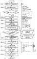
図9は表示に関する情報(画質調整パラメータ、画像表示エリア43のサイズ、及び倍率)に応じた画像処理結果を出力するまでの間、低解像度の画像を表示する処理の工程を示したフローチャートである
ステップS901からステップS905の処理は、第1の実施形態のステップS501からS505の処理と同様であるので、説明は省略する。FIG. 9 is a flowchart showing a process of displaying a low-resolution image until an image processing result corresponding to information related to display (image quality adjustment parameter, size of
ステップS906で、一時表示用の低解像度の画素を抽出する。前記抽出方法は、倍率が100%以下の間引き処理を画像全体に行う方法と同様である。 In step S906, low-resolution pixels for temporary display are extracted. The extraction method is the same as the method of performing the thinning process on the entire image with a magnification of 100% or less.
一時表示用の画像情報の解像度(倍率)は、一時表示として妥当な画質で処理時間が短いと体感できることを基準にして、操作者が予め設定登録するようにする。 The resolution (magnification) of the image information for temporary display is set and registered in advance by the operator on the basis that it can be experienced when the processing time is short with reasonable image quality for temporary display.
前記一時表示用の画像情報は、図10で後述するように画質調整時や表示情報に変更があった場合に利用できるため、RAM4の適当な領域に保持するものとするが、保存先はハードディスク装置8でも構わない。 Since the temporary display image information can be used when adjusting the image quality or when the display information is changed as will be described later with reference to FIG. 10, it is held in an appropriate area of the
ステップS907では、対象画素抽出処理を行う。この対象画素抽出処理後の画像情報は、第1の実施形態で説明した通り、キャッシュ領域に保持する。ただし、表示に関する情報に変更があるなど、この対象画素抽出処理後の画像情報を再利用できなくなった場合には、破棄するものとする。 In step S907, target pixel extraction processing is performed. The image information after the target pixel extraction processing is held in the cache area as described in the first embodiment. However, if the image information after the target pixel extraction process cannot be reused, such as when information related to display is changed, it is discarded.
ステップS908からステップS909の処理は、第1の実施形態のステップS506からS507の処理と同様である。 The processing from step S908 to step S909 is the same as the processing from step S506 to S507 in the first embodiment.
ステップS910で、一時表示用の画像情報に対して現像処理を行う。ステップS911では、ステップS910の画像処理結果を表示装置7の画像表示エリア43に出力する。これはステップS514の処理と同様である。この結果、真の現像処理が完了するまでの間でも、簡易的な画像が画像表示エリア43に表示されることになる。 In step S910, development processing is performed on the temporary display image information. In step S911, the image processing result in step S910 is output to the
ステップS912では、対象画素抽出処理後の画像情報に対して真の現像処理を行う。そして、ステップS913で、S912の画像処理結果を出力装置に出力する。これもステップS514の処理と同様である。 In step S912, true development processing is performed on the image information after the target pixel extraction processing. In step S913, the image processing result in S912 is output to the output device. This is also the same as the processing in step S514.
図10は、上記図9の処理を行った画像に対して、使用者が画質調整を再度行った場合に実行する処理を示すフローチャートである。FIG. 10 is a flowchart showing processing executed when the user performs image quality adjustment again on the image subjected to the processing of FIG.
先ず、ステップS1001で、ウインドウ45を介して操作者が設定したユーザー画質調整情報を読込む。これはステップS507と同様の処理である。 First, in step S1001, user image quality adjustment information set by the operator via the
ステップS1002で、ユーザー画質調整情報に変更があるかないかの判定を行う。そして、このステップS1002において、変更があったと判定された場合、ステップS1003からステップS1008の処理を行う。 In step S1002, it is determined whether there is any change in the user image quality adjustment information. If it is determined in step S1002 that there has been a change, the processing from step S1003 to step S1008 is performed.
ステップS1003では、変更したユーザー画質調整情報が色またはの明るさに関する調整のための再生パラメータであるか否か判定を行う。色または明るさに関する調整である再生パラメータとは、例えばコントラスト、カラーマトリックス、トーンカーブ、明度、彩度、色相、ホワイトバランスである。ステップS1003において色および/または輝度に関する調整情報に変更があったと判定された場合には、ステップS1004からステップS1006の処理を行う。 In step S1003, it is determined whether or not the changed user image quality adjustment information is a reproduction parameter for adjustment relating to color or brightness. The reproduction parameters that are adjustments related to color or brightness are, for example, contrast, color matrix, tone curve, brightness, saturation, hue, and white balance. If it is determined in step S1003 that there has been a change in the adjustment information regarding color and / or luminance, the processing from step S1004 to step S1006 is performed.
ステップS1004では、先のステップS906でRAMに保存していた一時表示用画像情報を読込む。一時表示用の画像情報がない場合(スクロール等で画像切り出し領域のサイズや位置が変更された場合)は、ステップS901からS906の処理を再度行い生成する。 In step S1004, the temporary display image information stored in the RAM in step S906 is read. When there is no image information for temporary display (when the size or position of the image cut-out area is changed by scrolling or the like), the processing from steps S901 to S906 is performed again and generated.
ステップS1005で、一時表示用の低解像度の画像情報に対して現像処理を行う。これはステップS910の処理と同様である。そして、ステップS1006において、S1005の一時表示用の画像に対する処理結果を画像表示エリア43に表示出力する(ステップS514,S911の処理と同様である)。 In step S1005, development processing is performed on low-resolution image information for temporary display. This is the same as the processing in step S910. In step S1006, the processing result for the temporary display image in S1005 is displayed and output in the image display area 43 (similar to the processing in steps S514 and S911).
ステップS1007では、例えばRAMに格納された対象画素抽出処理後の画像情報を読込む。対象画素抽出処理後の画像情報がない場合は、ステップS901からS905,S907の処理を再度行い生成する。 In step S1007, for example, image information after target pixel extraction processing stored in the RAM is read. If there is no image information after the target pixel extraction process, the process from steps S901 to S905 and S907 is performed again.
ステップS1008で、対象画素抽出処理後の画像情報に対する真の現像処理を行う(ステップS912の処理と同様である)。 In step S1008, true development processing is performed on the image information after the target pixel extraction processing (similar to the processing in step S912).
ステップS1009では、S1008の画像処理結果を画像表示エリア43に表示出力する(ステップS514,S913の処理と同様である)。 In step S1009, the image processing result in S1008 is displayed and output in the image display area 43 (similar to the processing in steps S514 and S913).
以上であるが、一時表示用の画像情報に関する現像処理は、一時表示として妥当な画質を保てるならば、ステップS912で用いる現像処理中の適当な処理を省略しても良い。例えば、シャープネス処理、スムージング処理、ノイズ除去処理などは、一時表示の画像のように解像度が低い画像に対しては、操作者の画質確認の対象とはなりにくいので、それらの処理を省くか、簡易な処理にしてしまってもよい。 As described above, in the development processing relating to the image information for temporary display, an appropriate processing during the development processing used in step S912 may be omitted as long as an appropriate image quality can be maintained for temporary display. For example, sharpness processing, smoothing processing, noise removal processing, etc. are not subject to the operator's image quality confirmation for images with low resolution such as temporarily displayed images. It may be a simple process.
また、本実施形態において表示に関する情報に変更があった場合、たとえば表示領域のスクロールや画像表示エリア43のサイズの変更があった場合、表示領域に該当する範囲の一時表示用の画像情報がキャッシュメモリに保持し、表示の切り替えが完了するまで前記一時表示用の画像を表示してもよい。または、ステップS910またはS1005のユーザが設定した現像パラメータに基づいて処理した一時表示用の縮小画像をキャッシュメモリに保持していれば、ステップS909とS911、またはステップS1004とS1005の処理を行わずにこの縮小画像をRAW画像が処理されるまで表示しておくことが出来るため、更に現像処理後の表示画像の切り替え時に発生するタイムラグを少なくし、スムーズな表示更新が可能である。 In addition, when there is a change in display-related information in the present embodiment, for example, when the display area is scrolled or the size of the
本実施形態において、一時表示用の画像情報は画像全体を間引いて抽出していたが、対象画素抽出処理同様に表示領域の該当する範囲のみを間引いて抽出してもよい。 In the present embodiment, the image information for temporary display is extracted by thinning out the entire image. However, only the corresponding range of the display area may be thinned out and extracted as in the target pixel extraction process.
本実施形態において、ユーザー画質調整情報によって一時表示用の画像の処理結果を表示するか否かを判定していたが、前記判定条件に加えて、対象画素抽出処理後の画素数と一時表示用の画素数を比較して、前者の方が少ない場合、もしくは差がほとんどない場合には一時表示用の画像の処理結果を表示しないという判定をしてもよい。差がほとんどない基準は処理速度の差が見込めるか見込めないかを、pixel数や各画像情報の読み込み速度から判断すればよい。 In this embodiment, whether or not to display the processing result of the image for temporary display is determined based on the user image quality adjustment information. In addition to the determination condition, the number of pixels after the target pixel extraction processing and the temporary display If the former is smaller or there is almost no difference, it may be determined that the processing result of the temporary display image is not displayed. A criterion with little difference can be determined from the number of pixels and the reading speed of each piece of image information whether or not a difference in processing speed can be expected.
本実施形態において、ステップS1008の処理中、ウインドウ45に対する操作が行われた場合、或いは、画像表示領域エリア43のサイズが変更された場合、或いは画像表示エリア内の画像のスクロール中では、ステップS1008の処理を中断し、ステップS1001の処理に戻り、処理をしなおせば、色および/または輝度の調整中に常に一時表示用画像が更新することが可能である。例えば、コントラストを調整するスライダーバーを操作中、リアルタイムに一時表示用画像の表示が更新するといった画像装置を提供することが可能である。 In the present embodiment, when an operation is performed on the
本実施形態において、処理を平行に行うことができる環境であるならば、ステップS1004〜S1005の処理と、ステップS1007〜S1008の処理を平行して行ってもよい。また前記の場合に、S1005よりS1008の処理の方が早く終われば、S1006の処理をせず、S1009の処理を行えばよい。 In the present embodiment, if it is an environment where the processing can be performed in parallel, the processing in steps S1004 to S1005 and the processing in steps S1007 to S1008 may be performed in parallel. In the above case, if the process of S1008 is completed earlier than S1005, the process of S1009 may be performed without performing the process of S1006.
以上説明したように第2の実施形態によれば、画像表示エリア43のサイズ変更、スクロール変更中や、ウインドウ45での画質調整した場合には、最終的な画像処理が完了するまでの間は、簡易的な一時表示用の画像を用いて画像表示エリア43に表示することで、第1の実施形態よりも更にスムーズな表示更新をする画像処理装置が提供できる。且つ、シャープネスやスムージングなどの調整の場合には、一時表示をしないことによって、詳細な比較ができる画像処理装置を提供可能になる。 As described above, according to the second embodiment, when the size of the
本実施の形態ではRAW画像として、撮像センサから出力された信号をA/D変換し、圧縮処理をしないデータを用いたが、A/D変換後に可逆圧縮したデータであってもよい。 In the present embodiment, as the RAW image, the signal output from the image sensor is A / D converted and data that is not compressed is used. However, the data may be reversibly compressed after A / D conversion.
また、他にRAW画像は、撮像センサから得られた、出力アナログ信号でも良いし、A/D変換を施した画像信号に、少なくともホワイトバランス処理を施していない段階のもの、撮像センサから得られた、A/D変換を施した画像信号に輝度信号と色信号に分ける色分離処理をしていない段階もの、あるいは、beyar配列等の色フィルタを用いた場合等、色フィルタからの出力信号を色補間処理していない段階のもの、いずれかであっても良い。 In addition, the RAW image may be an output analog signal obtained from the image sensor, or may be obtained from the image sensor at a stage where at least white balance processing is not performed on the image signal subjected to A / D conversion. The output signal from the color filter is used when the A / D-converted image signal is not subjected to color separation processing for separating the luminance signal and the color signal, or when a color filter such as a beyar array is used. Any of the stages that have not undergone color interpolation processing may be used.
なお、本実施形態では、撮像センサとしてCCDについて説明をしたが、CMOSセンサであっても同様である。多色感光層を持つセンサ等でも補間処理ではなく画素ごとの各色データを求めるが、他は同様である。 In the present embodiment, the CCD has been described as the image sensor, but the same applies to a CMOS sensor. A sensor having a multicolor photosensitive layer or the like obtains each color data for each pixel instead of interpolation processing, but the other is the same.
また、第1、第2の実施形態では、現像処理はCRT等のモニタに出力する処理として説明をしたが、RAW画像から再生パラメータに基づいて印刷を行い、再生するものも含まれる。 In the first and second embodiments, the development processing has been described as processing that is output to a monitor such as a CRT. However, the development processing includes printing from a RAW image based on the playback parameters and playback.
また、実施形態では、RAW画像データの各コンポーネントは12ビットとして説明したが、このビット数に限るものではなく、一般のJPEG Baseline符号化のように8ビットを超えるビット数であれば何ビットでも構わない。 In the embodiment, each component of the RAW image data is described as 12 bits. However, the number of bits is not limited to this, and any number of bits can be used as long as the number of bits exceeds 8 bits as in general JPEG Baseline encoding. I do not care.
また、実施形態で説明した処理は、デジタルカメラ等の撮像装置で撮像して得られた画像を入力するためのハードウェア(例えば、デジタルカメラが通常有するUSBインタフェース、もしくはデジタルカメラから取り出したメモリカード等の記憶媒体をアクセスする装置)を有するパーソナルコンピュータ等の汎用情報処理装置で実行されるアプリケーションプログラムで実現できるものであるから、本発明はコンピュータプログラムをその範疇とすることは明らかである。また、通常、コンピュータプログラムは、CD−ROM等のコンピュータ可読記憶媒体に格納されていて、それをコンピュータにセットしてシステムにコピーもしくはインストールすることで実行可能になるわけであるから、本発明は、そのようなコンピュータ可読記憶媒体をもその範疇とすることは明らかである。
The processing described in the embodiment is performed by hardware for inputting an image obtained by imaging with an imaging device such as a digital camera (for example, a USB interface that a digital camera normally has, or a memory card taken out from the digital camera). It is obvious that the present invention includes a computer program as its category because it can be realized by an application program executed by a general-purpose information processing apparatus such as a personal computer having a storage medium such as a storage medium. In addition, the computer program is normally stored in a computer-readable storage medium such as a CD-ROM, and can be executed by setting it in a computer and copying or installing it in the system. Obviously, such a computer-readable storage medium falls within the category.
Claims (19)
Translated fromJapaneseRAW画像データの画素数に対応する、表示するために用いる表示手段の表示領域の画素数の割合を示す表示倍率を、ユーザーの操作に応じて設定する倍率設定手段と、
RAW画像データを読み込む読込手段と、
RAW画像データに対する現像処理を行う現像手段と、
RAW画像データの全画素よりも少ない一部の画素であって、前記倍率設定手段で設定された表示倍率が等倍未満の場合には当該設定された表示倍率が小さいほど少ない割合の画素を、前記RAW画像データから抽出する抽出手段と、
RAW画像データのうち、該RAW画像データの全画素ではなく、前記抽出手段で抽出した一部の画素を対象として前記現像手段による前記現像処理を行うように制御する制御手段と、
前記現像手段による前記一部の画素を対象とした現像処理によって得られた画像データを前記表示領域に表示するように制御する表示制御手段と
を備えることを特徴とする画像処理装置。An image processing apparatus for developing RAW image data obtained from an imaging apparatus having an imaging sensor,
A magnification setting means for setting a display magnification corresponding to the number of pixels of the RAW image data and indicating a ratio of the number of pixels in the display area of the display means used for display according to a user operation;
Reading means for reading RAW image data;
Development means for performing development processing on RAW image data;
If some of the pixels are smaller than all the pixels of the RAW image data,and the display magnification set by the magnification setting means is less than 1 ×, the smaller the set display magnification, the smaller the proportion of pixels. Extracting meansfor extractingfrom the RAW image data ;
Control means for controlling the development processing by the development means for a part of the pixels extracted by the extraction means instead of all the pixels of the raw image data among the raw image data;
An image processing apparatus,comprising:display control meansfor controlling image data obtained by the development processing for the some pixels by the developing means tobedisplayed in thedisplay area.
ユーザーの操作に応じて、画像を表示するための表示領域のサイズを設定する領域サイズ設定手段と、
RAW画像データを読み込む読込手段と、
RAW画像データに対する現像処理を行う現像手段と、
前記領域サイズ設定手段で前記表示領域のサイズが設定されたことに応じて、RAW画像データの全画素よりも少ない一部の画素であって、前記領域サイズ設定手段で設定された現在のサイズの表示領域に対応する、前記RAW画像データにおける領域のサイズを算出し、前記RAW画像データから、算出した領域内の画素を抽出する抽出手段と、
RAW画像データのうち、該RAW画像データの全画素ではなく、前記抽出手段で抽出した一部の画像データを対象として前記現像手段による前記現像処理を行うように制御する制御手段と、
前記現像手段による前記一部の画素を対象とした現像処理によって得られた画像データを、表示手段の前記表示領域に表示するように制御する表示制御手段と
を備えることを特徴とする画像処理装置。An image processing apparatus for developing RAW image data obtained from an imaging apparatus having an imaging sensor,
An area size setting means for setting a size of a display area for displaying an image according to a user operation;
Reading means for reading RAW image data;
Development means for performing development processing on RAW image data;
In response to the setting of the size of the display area by the area size setting means, some of the pixelsofthe RAW image data are smaller than all the pixels, and the current size set by the area size setting means An extraction unitthat calculates a size of a region in the RAW image data corresponding to a display region, and extractspixels in the calculated region from the RAW image data ;
Control means for controlling the development processing by the development means for a part of theimage data extracted by the extraction means instead of all the pixels of the raw image data among the raw image data;
An image processing apparatuscomprising:a display control unit configuredto control image data obtained by the development process for the some pixels by the development unit tobedisplayed in thedisplay area of thedisplay unit. .
前記抽出手段は、前記倍率設定手段で設定された表示倍率が等倍未満の場合には当該設定された表示倍率が小さいほど少ない割合の画素を、前記RAW画像データから抽出することを特徴とする請求項2又は3に記載の画像処理装置。A magnification setting means for setting a display magnification corresponding to the number of pixels of the RAW image data and indicating a ratio of the number of pixels in the display area of the display means used for display according to a user operation;
Whenthe display magnification set by the magnification setting device is less than 1 × , the extraction unit extracts asmaller percentage of pixels from the RAW image data as the set display magnification is smaller. The image processing apparatus accordingto claim2 .
前記現像手段は、前記パラメータ設定手段で設定されたパラメータに基づいて前記現像処理を行うことを特徴とする請求項1乃至7のいずれか1項に記載の画像処理装置。Further comprising parameter setting means for setting the parameters of the development processing in accordance with a user operation,
The developing unit is an image processing apparatus according to any one of claims 1 to7, characterized in that the developing processing based on the parameters set by the parameter setting means.
前記現像手段は、前記表示領域へ表示する画像の倍率が等倍未満の場合のシャープネス処理は、該倍率が等倍以上のシャープネス処理よりも簡易な処理を行うあるいはシャープネス処理を行わないことを特徴とする請求項8または9に記載の画像処理装置。Parameters that can be set by the parameter setting means include sharpness processing parameters,
The developing means is characterized in that the sharpness processing when the magnification of the imagedisplayed in thedisplay area is less than 1 × is simpler than the sharpness processing with the magnification of 1 × or more, or is not subjected to sharpness processing. The image processing apparatus according to claim8 or9 .
前記生成手段で生成された前記一次表示用画像データを保持する保持手段とを更に有し、
前記制御手段は、前記抽出手段で抽出した前記一部の画素を対象とした前記現像処理を行う際に、前記保持手段によって保持されている前記一次表示用画像データに対する前記現像処理である予備現像処理を行うように制御し、前記抽出手段で抽出した前記一部の画素を対象とした前記現像処理が完了するまでの間、前記予備画像処理によって得られた画像データを前記表示領域に表示するように制御することを特徴とする請求項1乃至10のいずれか1項に記載の画像処理装置。Generating means for thinning out raw image data at a predetermined thinning rate to generate primary display image data having a low number of pixels;
Holding means for holding the primary display image data generated by the generating means;
The control means is a preliminary development which is the development process for the primary display image data held by the holding means when performing the development process for the some pixels extracted by the extraction means. The image data obtained by the preliminary image processing isdisplayed in thedisplay area until the development processing for the part of pixels extracted by the extraction unit is completed. The image processing apparatus according to claim 1, wherein the image processing apparatus is controlled as follows.
RAW画像データの画素数に対応する、表示するために用いる表示手段の表示領域の画素数の割合を示す表示倍率を、ユーザーの操作に応じて設定する倍率設定工程と、
RAW画像データを読み込む読込工程と、
RAW画像データに対する現像処理を行う現像工程と、
RAW画像データの全画素よりも少ない一部の画素であって、前記倍率設定工程で設定された表示倍率が等倍未満の場合には当該設定された表示倍率が小さいほど少ない割合の画素を、前記RAW画像データから抽出する抽出工程と、
RAW画像データのうち、該RAW画像データの全画素ではなく、前記抽出工程で抽出した一部の画素を対象として前記現像工程による前記現像処理を行うように制御する制御工程と、
前記現像工程による前記一部の画素を対象とした現像処理によって得られた画像データを前記表示領域に表示するように制御する表示制御工程と
を備えることを特徴とする画像処理装置の制御方法。An image processing apparatus control method for developing RAW image data obtained from an imaging apparatus having an imaging sensor,
A magnification setting step for setting a display magnification corresponding to the number of pixels of the RAW image data and indicating a ratio of the number of pixels in the display area of the display means used for display in accordance with a user operation;
A reading process for reading RAW image data;
A development process for performing development processing on the RAW image data;
When some of the pixels are smaller than all the pixels of the RAW image data,and the display magnification set in the magnification setting step is less than 1 ×, the smaller the set display magnification, the smaller the proportion of pixels. An extraction step of extractingfrom the RAW image data ;
A control step for controlling the development processing by the development step for a part of the pixels extracted in the extraction step instead of all the pixels of the raw image data among the raw image data;
Anda display control stepof controlling the image data obtained by the development processing for the part of pixels in the development step tobedisplayed in thedisplay area.
Priority Applications (4)
| Application Number | Priority Date | Filing Date | Title |
|---|---|---|---|
| JP2005000910AJP4845382B2 (en) | 2004-02-06 | 2005-01-05 | Image processing apparatus, control method therefor, computer program, and computer-readable storage medium |
| US11/048,756US7424171B2 (en) | 2004-02-06 | 2005-02-03 | Image processing method and apparatus, computer program, and computer readable storage medium |
| US12/120,371US8094966B2 (en) | 2004-02-06 | 2008-05-14 | Image processing method and apparatus, computer program, and computer-readable storage medium |
| US13/324,258US8483509B2 (en) | 2004-02-06 | 2011-12-13 | Image processing method and apparatus, computer program, and computer-readable storage medium |
Applications Claiming Priority (3)
| Application Number | Priority Date | Filing Date | Title |
|---|---|---|---|
| JP2004031401 | 2004-02-06 | ||
| JP2004031401 | 2004-02-06 | ||
| JP2005000910AJP4845382B2 (en) | 2004-02-06 | 2005-01-05 | Image processing apparatus, control method therefor, computer program, and computer-readable storage medium |
Publications (3)
| Publication Number | Publication Date |
|---|---|
| JP2005251166A JP2005251166A (en) | 2005-09-15 |
| JP2005251166A5 JP2005251166A5 (en) | 2008-02-14 |
| JP4845382B2true JP4845382B2 (en) | 2011-12-28 |
Family
ID=34829458
Family Applications (1)
| Application Number | Title | Priority Date | Filing Date |
|---|---|---|---|
| JP2005000910AExpired - Fee RelatedJP4845382B2 (en) | 2004-02-06 | 2005-01-05 | Image processing apparatus, control method therefor, computer program, and computer-readable storage medium |
Country Status (2)
| Country | Link |
|---|---|
| US (3) | US7424171B2 (en) |
| JP (1) | JP4845382B2 (en) |
Families Citing this family (424)
| Publication number | Priority date | Publication date | Assignee | Title |
|---|---|---|---|---|
| US20070084897A1 (en) | 2003-05-20 | 2007-04-19 | Shelton Frederick E Iv | Articulating surgical stapling instrument incorporating a two-piece e-beam firing mechanism |
| US9060770B2 (en) | 2003-05-20 | 2015-06-23 | Ethicon Endo-Surgery, Inc. | Robotically-driven surgical instrument with E-beam driver |
| US8215531B2 (en) | 2004-07-28 | 2012-07-10 | Ethicon Endo-Surgery, Inc. | Surgical stapling instrument having a medical substance dispenser |
| US9072535B2 (en) | 2011-05-27 | 2015-07-07 | Ethicon Endo-Surgery, Inc. | Surgical stapling instruments with rotatable staple deployment arrangements |
| US11998198B2 (en) | 2004-07-28 | 2024-06-04 | Cilag Gmbh International | Surgical stapling instrument incorporating a two-piece E-beam firing mechanism |
| US11890012B2 (en) | 2004-07-28 | 2024-02-06 | Cilag Gmbh International | Staple cartridge comprising cartridge body and attached support |
| JP4640579B2 (en)* | 2005-01-27 | 2011-03-02 | ソニー株式会社 | Information processing apparatus and recovery board |
| US20060173934A1 (en)* | 2005-02-02 | 2006-08-03 | Gateway | Saving documents on multiple drives |
| US7893949B2 (en)* | 2005-07-26 | 2011-02-22 | Brother Kogyo Kabushiki Kaisha | Image display apparatus |
| US10159482B2 (en) | 2005-08-31 | 2018-12-25 | Ethicon Llc | Fastener cartridge assembly comprising a fixed anvil and different staple heights |
| US7669746B2 (en) | 2005-08-31 | 2010-03-02 | Ethicon Endo-Surgery, Inc. | Staple cartridges for forming staples having differing formed staple heights |
| US7934630B2 (en) | 2005-08-31 | 2011-05-03 | Ethicon Endo-Surgery, Inc. | Staple cartridges for forming staples having differing formed staple heights |
| US11246590B2 (en) | 2005-08-31 | 2022-02-15 | Cilag Gmbh International | Staple cartridge including staple drivers having different unfired heights |
| JP4586684B2 (en)* | 2005-08-31 | 2010-11-24 | ソニー株式会社 | Information processing apparatus and method, and program |
| US9237891B2 (en) | 2005-08-31 | 2016-01-19 | Ethicon Endo-Surgery, Inc. | Robotically-controlled surgical stapling devices that produce formed staples having different lengths |
| US11484312B2 (en) | 2005-08-31 | 2022-11-01 | Cilag Gmbh International | Staple cartridge comprising a staple driver arrangement |
| JP4720387B2 (en)* | 2005-09-07 | 2011-07-13 | ソニー株式会社 | Imaging apparatus, image processing apparatus and method, and computer program |
| JP4752421B2 (en)* | 2005-09-22 | 2011-08-17 | セイコーエプソン株式会社 | Image retouching method, image retouching device, and image retouching program |
| JP4592099B2 (en)* | 2005-09-29 | 2010-12-01 | キヤノン株式会社 | Image display device and image display method |
| JP4962295B2 (en)* | 2005-09-30 | 2012-06-27 | セイコーエプソン株式会社 | Image processing apparatus and image processing program |
| JP4935049B2 (en)* | 2005-10-27 | 2012-05-23 | セイコーエプソン株式会社 | Image processing apparatus, image processing method, and image processing program |
| US20070106317A1 (en) | 2005-11-09 | 2007-05-10 | Shelton Frederick E Iv | Hydraulically and electrically actuated articulation joints for surgical instruments |
| US7845537B2 (en) | 2006-01-31 | 2010-12-07 | Ethicon Endo-Surgery, Inc. | Surgical instrument having recording capabilities |
| US7753904B2 (en) | 2006-01-31 | 2010-07-13 | Ethicon Endo-Surgery, Inc. | Endoscopic surgical instrument with a handle that can articulate with respect to the shaft |
| US8820603B2 (en) | 2006-01-31 | 2014-09-02 | Ethicon Endo-Surgery, Inc. | Accessing data stored in a memory of a surgical instrument |
| US20110295295A1 (en) | 2006-01-31 | 2011-12-01 | Ethicon Endo-Surgery, Inc. | Robotically-controlled surgical instrument having recording capabilities |
| US8708213B2 (en) | 2006-01-31 | 2014-04-29 | Ethicon Endo-Surgery, Inc. | Surgical instrument having a feedback system |
| US8186555B2 (en) | 2006-01-31 | 2012-05-29 | Ethicon Endo-Surgery, Inc. | Motor-driven surgical cutting and fastening instrument with mechanical closure system |
| US11224427B2 (en) | 2006-01-31 | 2022-01-18 | Cilag Gmbh International | Surgical stapling system including a console and retraction assembly |
| US20110024477A1 (en) | 2009-02-06 | 2011-02-03 | Hall Steven G | Driven Surgical Stapler Improvements |
| US11793518B2 (en) | 2006-01-31 | 2023-10-24 | Cilag Gmbh International | Powered surgical instruments with firing system lockout arrangements |
| US20120292367A1 (en) | 2006-01-31 | 2012-11-22 | Ethicon Endo-Surgery, Inc. | Robotically-controlled end effector |
| US11278279B2 (en) | 2006-01-31 | 2022-03-22 | Cilag Gmbh International | Surgical instrument assembly |
| US8992422B2 (en) | 2006-03-23 | 2015-03-31 | Ethicon Endo-Surgery, Inc. | Robotically-controlled endoscopic accessory channel |
| JP2007328555A (en)* | 2006-06-08 | 2007-12-20 | Hitachi Ltd | Video correction device |
| US8322455B2 (en) | 2006-06-27 | 2012-12-04 | Ethicon Endo-Surgery, Inc. | Manually driven surgical cutting and fastening instrument |
| US10568652B2 (en) | 2006-09-29 | 2020-02-25 | Ethicon Llc | Surgical staples having attached drivers of different heights and stapling instruments for deploying the same |
| US11980366B2 (en) | 2006-10-03 | 2024-05-14 | Cilag Gmbh International | Surgical instrument |
| US11291441B2 (en) | 2007-01-10 | 2022-04-05 | Cilag Gmbh International | Surgical instrument with wireless communication between control unit and remote sensor |
| US8632535B2 (en) | 2007-01-10 | 2014-01-21 | Ethicon Endo-Surgery, Inc. | Interlock and surgical instrument including same |
| US8684253B2 (en) | 2007-01-10 | 2014-04-01 | Ethicon Endo-Surgery, Inc. | Surgical instrument with wireless communication between a control unit of a robotic system and remote sensor |
| US11039836B2 (en) | 2007-01-11 | 2021-06-22 | Cilag Gmbh International | Staple cartridge for use with a surgical stapling instrument |
| US20080169333A1 (en) | 2007-01-11 | 2008-07-17 | Shelton Frederick E | Surgical stapler end effector with tapered distal end |
| US7673782B2 (en) | 2007-03-15 | 2010-03-09 | Ethicon Endo-Surgery, Inc. | Surgical stapling instrument having a releasable buttress material |
| JP4886571B2 (en)* | 2007-03-28 | 2012-02-29 | キヤノン株式会社 | Imaging apparatus, image processing apparatus, image processing system, control method thereof, and program |
| US8931682B2 (en) | 2007-06-04 | 2015-01-13 | Ethicon Endo-Surgery, Inc. | Robotically-controlled shaft based rotary drive systems for surgical instruments |
| US11564682B2 (en) | 2007-06-04 | 2023-01-31 | Cilag Gmbh International | Surgical stapler device |
| US7753245B2 (en) | 2007-06-22 | 2010-07-13 | Ethicon Endo-Surgery, Inc. | Surgical stapling instruments |
| JP4614363B2 (en)* | 2007-06-29 | 2011-01-19 | キヤノンマーケティングジャパン株式会社 | Information processing apparatus and information processing method |
| US11849941B2 (en) | 2007-06-29 | 2023-12-26 | Cilag Gmbh International | Staple cartridge having staple cavities extending at a transverse angle relative to a longitudinal cartridge axis |
| US8636736B2 (en) | 2008-02-14 | 2014-01-28 | Ethicon Endo-Surgery, Inc. | Motorized surgical cutting and fastening instrument |
| US9179912B2 (en) | 2008-02-14 | 2015-11-10 | Ethicon Endo-Surgery, Inc. | Robotically-controlled motorized surgical cutting and fastening instrument |
| US7819298B2 (en) | 2008-02-14 | 2010-10-26 | Ethicon Endo-Surgery, Inc. | Surgical stapling apparatus with control features operable with one hand |
| JP5410110B2 (en) | 2008-02-14 | 2014-02-05 | エシコン・エンド−サージェリィ・インコーポレイテッド | Surgical cutting / fixing instrument with RF electrode |
| US7866527B2 (en) | 2008-02-14 | 2011-01-11 | Ethicon Endo-Surgery, Inc. | Surgical stapling apparatus with interlockable firing system |
| US11986183B2 (en) | 2008-02-14 | 2024-05-21 | Cilag Gmbh International | Surgical cutting and fastening instrument comprising a plurality of sensors to measure an electrical parameter |
| US8758391B2 (en) | 2008-02-14 | 2014-06-24 | Ethicon Endo-Surgery, Inc. | Interchangeable tools for surgical instruments |
| US8573465B2 (en) | 2008-02-14 | 2013-11-05 | Ethicon Endo-Surgery, Inc. | Robotically-controlled surgical end effector system with rotary actuated closure systems |
| US9585657B2 (en) | 2008-02-15 | 2017-03-07 | Ethicon Endo-Surgery, Llc | Actuator for releasing a layer of material from a surgical end effector |
| US8355070B2 (en)* | 2008-05-23 | 2013-01-15 | Seiko Epson Corporation | Development processing device, development processing method, and storage medium of computer program for development process for developing undeveloped image data |
| JP2010026734A (en)* | 2008-07-17 | 2010-02-04 | Canon Inc | Image processor and its method |
| US11648005B2 (en) | 2008-09-23 | 2023-05-16 | Cilag Gmbh International | Robotically-controlled motorized surgical instrument with an end effector |
| US9386983B2 (en) | 2008-09-23 | 2016-07-12 | Ethicon Endo-Surgery, Llc | Robotically-controlled motorized surgical instrument |
| US9005230B2 (en) | 2008-09-23 | 2015-04-14 | Ethicon Endo-Surgery, Inc. | Motorized surgical instrument |
| US8210411B2 (en) | 2008-09-23 | 2012-07-03 | Ethicon Endo-Surgery, Inc. | Motor-driven surgical cutting instrument |
| US8608045B2 (en) | 2008-10-10 | 2013-12-17 | Ethicon Endo-Sugery, Inc. | Powered surgical cutting and stapling apparatus with manually retractable firing system |
| US8517239B2 (en) | 2009-02-05 | 2013-08-27 | Ethicon Endo-Surgery, Inc. | Surgical stapling instrument comprising a magnetic element driver |
| RU2525225C2 (en) | 2009-02-06 | 2014-08-10 | Этикон Эндо-Серджери, Инк. | Improvement of drive surgical suturing instrument |
| JP2010193186A (en)* | 2009-02-18 | 2010-09-02 | Nikon Corp | Image editing device, imaging apparatus and image editing program |
| JP5371489B2 (en)* | 2009-03-05 | 2013-12-18 | キヤノン株式会社 | Image management apparatus, control method therefor, program, and storage medium |
| DE102009021974A1 (en)* | 2009-05-19 | 2011-03-03 | Mobotix Ag | Digital video camera |
| JP5326912B2 (en)* | 2009-07-31 | 2013-10-30 | ブラザー工業株式会社 | Printing device, composite image data generation device, and composite image data generation program |
| US8851354B2 (en) | 2009-12-24 | 2014-10-07 | Ethicon Endo-Surgery, Inc. | Surgical cutting instrument that analyzes tissue thickness |
| US8220688B2 (en) | 2009-12-24 | 2012-07-17 | Ethicon Endo-Surgery, Inc. | Motor-driven surgical cutting instrument with electric actuator directional control assembly |
| US8783543B2 (en) | 2010-07-30 | 2014-07-22 | Ethicon Endo-Surgery, Inc. | Tissue acquisition arrangements and methods for surgical stapling devices |
| US10945731B2 (en) | 2010-09-30 | 2021-03-16 | Ethicon Llc | Tissue thickness compensator comprising controlled release and expansion |
| US9629814B2 (en) | 2010-09-30 | 2017-04-25 | Ethicon Endo-Surgery, Llc | Tissue thickness compensator configured to redistribute compressive forces |
| US11812965B2 (en) | 2010-09-30 | 2023-11-14 | Cilag Gmbh International | Layer of material for a surgical end effector |
| US9016542B2 (en) | 2010-09-30 | 2015-04-28 | Ethicon Endo-Surgery, Inc. | Staple cartridge comprising compressible distortion resistant components |
| US11298125B2 (en) | 2010-09-30 | 2022-04-12 | Cilag Gmbh International | Tissue stapler having a thickness compensator |
| US9386988B2 (en) | 2010-09-30 | 2016-07-12 | Ethicon End-Surgery, LLC | Retainer assembly including a tissue thickness compensator |
| US9788834B2 (en) | 2010-09-30 | 2017-10-17 | Ethicon Llc | Layer comprising deployable attachment members |
| US11925354B2 (en) | 2010-09-30 | 2024-03-12 | Cilag Gmbh International | Staple cartridge comprising staples positioned within a compressible portion thereof |
| US12213666B2 (en) | 2010-09-30 | 2025-02-04 | Cilag Gmbh International | Tissue thickness compensator comprising layers |
| US9351730B2 (en) | 2011-04-29 | 2016-05-31 | Ethicon Endo-Surgery, Llc | Tissue thickness compensator comprising channels |
| US8695866B2 (en) | 2010-10-01 | 2014-04-15 | Ethicon Endo-Surgery, Inc. | Surgical instrument having a power control circuit |
| TWI432778B (en)* | 2010-12-08 | 2014-04-01 | Largan Precision Co Ltd | Calibration method and apparatus for optical imaging lens system with double optical traces |
| AU2012250197B2 (en) | 2011-04-29 | 2017-08-10 | Ethicon Endo-Surgery, Inc. | Staple cartridge comprising staples positioned within a compressible portion thereof |
| JP5665655B2 (en)* | 2011-05-24 | 2015-02-04 | 株式会社日立製作所 | Image processing apparatus and method |
| US11207064B2 (en) | 2011-05-27 | 2021-12-28 | Cilag Gmbh International | Automated end effector component reloading system for use with a robotic system |
| TWI455579B (en)* | 2011-10-26 | 2014-10-01 | Ability Entpr Co Ltd | Image capturing method and image processing system and image capturing device thereof |
| US9044230B2 (en) | 2012-02-13 | 2015-06-02 | Ethicon Endo-Surgery, Inc. | Surgical cutting and fastening instrument with apparatus for determining cartridge and firing motion status |
| ITRN20120019A1 (en)* | 2012-03-24 | 2013-09-25 | Photosi Spa | PROCEDURE FOR MODIFICATION OF DIGITAL PHOTOGRAPHS BY HARDWARE DEVICES EQUIPPED WITH AT LEAST ONE DISPLAY SCREEN AND APPLICATION SOFTWARE FOR THIS PROCEDURE. |
| BR112014024098B1 (en) | 2012-03-28 | 2021-05-25 | Ethicon Endo-Surgery, Inc. | staple cartridge |
| JP6224070B2 (en) | 2012-03-28 | 2017-11-01 | エシコン・エンド−サージェリィ・インコーポレイテッドEthicon Endo−Surgery,Inc. | Retainer assembly including tissue thickness compensator |
| MX358135B (en) | 2012-03-28 | 2018-08-06 | Ethicon Endo Surgery Inc | Tissue thickness compensator comprising a plurality of layers. |
| JP6003199B2 (en)* | 2012-05-08 | 2016-10-05 | ソニー株式会社 | Interchangeable lens camera system and lens data acquisition program |
| US9101358B2 (en) | 2012-06-15 | 2015-08-11 | Ethicon Endo-Surgery, Inc. | Articulatable surgical instrument comprising a firing drive |
| US20140001231A1 (en) | 2012-06-28 | 2014-01-02 | Ethicon Endo-Surgery, Inc. | Firing system lockout arrangements for surgical instruments |
| JP6290201B2 (en) | 2012-06-28 | 2018-03-07 | エシコン・エンド−サージェリィ・インコーポレイテッドEthicon Endo−Surgery,Inc. | Lockout for empty clip cartridge |
| US9408606B2 (en) | 2012-06-28 | 2016-08-09 | Ethicon Endo-Surgery, Llc | Robotically powered surgical device with manually-actuatable reversing system |
| US11278284B2 (en) | 2012-06-28 | 2022-03-22 | Cilag Gmbh International | Rotary drive arrangements for surgical instruments |
| US9282974B2 (en) | 2012-06-28 | 2016-03-15 | Ethicon Endo-Surgery, Llc | Empty clip cartridge lockout |
| BR112014032776B1 (en) | 2012-06-28 | 2021-09-08 | Ethicon Endo-Surgery, Inc | SURGICAL INSTRUMENT SYSTEM AND SURGICAL KIT FOR USE WITH A SURGICAL INSTRUMENT SYSTEM |
| US9289256B2 (en) | 2012-06-28 | 2016-03-22 | Ethicon Endo-Surgery, Llc | Surgical end effectors having angled tissue-contacting surfaces |
| US12383267B2 (en) | 2012-06-28 | 2025-08-12 | Cilag Gmbh International | Robotically powered surgical device with manually-actuatable reversing system |
| RU2672520C2 (en) | 2013-03-01 | 2018-11-15 | Этикон Эндо-Серджери, Инк. | Hingedly turnable surgical instruments with conducting ways for signal transfer |
| BR112015021082B1 (en) | 2013-03-01 | 2022-05-10 | Ethicon Endo-Surgery, Inc | surgical instrument |
| US9629629B2 (en) | 2013-03-14 | 2017-04-25 | Ethicon Endo-Surgey, LLC | Control systems for surgical instruments |
| US9808244B2 (en) | 2013-03-14 | 2017-11-07 | Ethicon Llc | Sensor arrangements for absolute positioning system for surgical instruments |
| WO2014141637A1 (en) | 2013-03-15 | 2014-09-18 | Canon Kabushiki Kaisha | Imaging apparatus and imaging apparatus control method |
| JP2014179851A (en)* | 2013-03-15 | 2014-09-25 | Canon Inc | Imaging apparatus and control method of the same |
| US9826976B2 (en) | 2013-04-16 | 2017-11-28 | Ethicon Llc | Motor driven surgical instruments with lockable dual drive shafts |
| BR112015026109B1 (en) | 2013-04-16 | 2022-02-22 | Ethicon Endo-Surgery, Inc | surgical instrument |
| JP2015015699A (en) | 2013-06-07 | 2015-01-22 | キヤノン株式会社 | Image processing apparatus, information processing method, and program |
| US9775609B2 (en) | 2013-08-23 | 2017-10-03 | Ethicon Llc | Tamper proof circuit for surgical instrument battery pack |
| MX369362B (en) | 2013-08-23 | 2019-11-06 | Ethicon Endo Surgery Llc | Firing member retraction devices for powered surgical instruments. |
| US9962161B2 (en) | 2014-02-12 | 2018-05-08 | Ethicon Llc | Deliverable surgical instrument |
| US12232723B2 (en) | 2014-03-26 | 2025-02-25 | Cilag Gmbh International | Systems and methods for controlling a segmented circuit |
| BR112016021943B1 (en) | 2014-03-26 | 2022-06-14 | Ethicon Endo-Surgery, Llc | SURGICAL INSTRUMENT FOR USE BY AN OPERATOR IN A SURGICAL PROCEDURE |
| US20150272580A1 (en) | 2014-03-26 | 2015-10-01 | Ethicon Endo-Surgery, Inc. | Verification of number of battery exchanges/procedure count |
| US10013049B2 (en) | 2014-03-26 | 2018-07-03 | Ethicon Llc | Power management through sleep options of segmented circuit and wake up control |
| US10004497B2 (en) | 2014-03-26 | 2018-06-26 | Ethicon Llc | Interface systems for use with surgical instruments |
| KR102388780B1 (en)* | 2014-04-02 | 2022-04-19 | 에어다이 인텔렉츄얼 프로퍼티 엘엘씨 | Color management |
| JP6376813B2 (en)* | 2014-04-07 | 2018-08-22 | キヤノン株式会社 | Image processing apparatus, image processing method and program, and imaging apparatus |
| US10327764B2 (en) | 2014-09-26 | 2019-06-25 | Ethicon Llc | Method for creating a flexible staple line |
| CN106456159B (en) | 2014-04-16 | 2019-03-08 | 伊西康内外科有限责任公司 | Fastener Cartridge Assembly and Nail Retainer Cover Arrangement |
| US10470768B2 (en) | 2014-04-16 | 2019-11-12 | Ethicon Llc | Fastener cartridge including a layer attached thereto |
| US20150297225A1 (en) | 2014-04-16 | 2015-10-22 | Ethicon Endo-Surgery, Inc. | Fastener cartridges including extensions having different configurations |
| BR112016023825B1 (en) | 2014-04-16 | 2022-08-02 | Ethicon Endo-Surgery, Llc | STAPLE CARTRIDGE FOR USE WITH A SURGICAL STAPLER AND STAPLE CARTRIDGE FOR USE WITH A SURGICAL INSTRUMENT |
| CN106456176B (en) | 2014-04-16 | 2019-06-28 | 伊西康内外科有限责任公司 | Fastener Cartridge Including Extensions With Different Configurations |
| US10135242B2 (en) | 2014-09-05 | 2018-11-20 | Ethicon Llc | Smart cartridge wake up operation and data retention |
| US11311294B2 (en) | 2014-09-05 | 2022-04-26 | Cilag Gmbh International | Powered medical device including measurement of closure state of jaws |
| BR112017004361B1 (en) | 2014-09-05 | 2023-04-11 | Ethicon Llc | ELECTRONIC SYSTEM FOR A SURGICAL INSTRUMENT |
| US10105142B2 (en) | 2014-09-18 | 2018-10-23 | Ethicon Llc | Surgical stapler with plurality of cutting elements |
| CN107427300B (en) | 2014-09-26 | 2020-12-04 | 伊西康有限责任公司 | Surgical suture buttresses and auxiliary materials |
| US11523821B2 (en) | 2014-09-26 | 2022-12-13 | Cilag Gmbh International | Method for creating a flexible staple line |
| US10076325B2 (en) | 2014-10-13 | 2018-09-18 | Ethicon Llc | Surgical stapling apparatus comprising a tissue stop |
| US9924944B2 (en) | 2014-10-16 | 2018-03-27 | Ethicon Llc | Staple cartridge comprising an adjunct material |
| US11141153B2 (en) | 2014-10-29 | 2021-10-12 | Cilag Gmbh International | Staple cartridges comprising driver arrangements |
| US10517594B2 (en) | 2014-10-29 | 2019-12-31 | Ethicon Llc | Cartridge assemblies for surgical staplers |
| US9844376B2 (en) | 2014-11-06 | 2017-12-19 | Ethicon Llc | Staple cartridge comprising a releasable adjunct material |
| US10736636B2 (en) | 2014-12-10 | 2020-08-11 | Ethicon Llc | Articulatable surgical instrument system |
| US9844374B2 (en) | 2014-12-18 | 2017-12-19 | Ethicon Llc | Surgical instrument systems comprising an articulatable end effector and means for adjusting the firing stroke of a firing member |
| US9987000B2 (en) | 2014-12-18 | 2018-06-05 | Ethicon Llc | Surgical instrument assembly comprising a flexible articulation system |
| US10085748B2 (en) | 2014-12-18 | 2018-10-02 | Ethicon Llc | Locking arrangements for detachable shaft assemblies with articulatable surgical end effectors |
| US9844375B2 (en) | 2014-12-18 | 2017-12-19 | Ethicon Llc | Drive arrangements for articulatable surgical instruments |
| MX389118B (en) | 2014-12-18 | 2025-03-20 | Ethicon Llc | SURGICAL INSTRUMENT WITH AN ANVIL THAT CAN BE SELECTIVELY MOVED ON A DISCRETE, NON-MOBILE AXIS RELATIVE TO A STAPLE CARTRIDGE. |
| US9943309B2 (en) | 2014-12-18 | 2018-04-17 | Ethicon Llc | Surgical instruments with articulatable end effectors and movable firing beam support arrangements |
| US11154301B2 (en) | 2015-02-27 | 2021-10-26 | Cilag Gmbh International | Modular stapling assembly |
| US10687806B2 (en) | 2015-03-06 | 2020-06-23 | Ethicon Llc | Adaptive tissue compression techniques to adjust closure rates for multiple tissue types |
| US10548504B2 (en) | 2015-03-06 | 2020-02-04 | Ethicon Llc | Overlaid multi sensor radio frequency (RF) electrode system to measure tissue compression |
| JP2020121162A (en) | 2015-03-06 | 2020-08-13 | エシコン エルエルシーEthicon LLC | Time dependent evaluation of sensor data to determine stability element, creep element and viscoelastic element of measurement |
| US10441279B2 (en) | 2015-03-06 | 2019-10-15 | Ethicon Llc | Multiple level thresholds to modify operation of powered surgical instruments |
| US9901342B2 (en) | 2015-03-06 | 2018-02-27 | Ethicon Endo-Surgery, Llc | Signal and power communication system positioned on a rotatable shaft |
| US10245033B2 (en) | 2015-03-06 | 2019-04-02 | Ethicon Llc | Surgical instrument comprising a lockable battery housing |
| US9993248B2 (en) | 2015-03-06 | 2018-06-12 | Ethicon Endo-Surgery, Llc | Smart sensors with local signal processing |
| US10617412B2 (en) | 2015-03-06 | 2020-04-14 | Ethicon Llc | System for detecting the mis-insertion of a staple cartridge into a surgical stapler |
| US10433844B2 (en) | 2015-03-31 | 2019-10-08 | Ethicon Llc | Surgical instrument with selectively disengageable threaded drive systems |
| US10835249B2 (en) | 2015-08-17 | 2020-11-17 | Ethicon Llc | Implantable layers for a surgical instrument |
| US10105139B2 (en) | 2015-09-23 | 2018-10-23 | Ethicon Llc | Surgical stapler having downstream current-based motor control |
| US10238386B2 (en) | 2015-09-23 | 2019-03-26 | Ethicon Llc | Surgical stapler having motor control based on an electrical parameter related to a motor current |
| US10299878B2 (en) | 2015-09-25 | 2019-05-28 | Ethicon Llc | Implantable adjunct systems for determining adjunct skew |
| US10433846B2 (en) | 2015-09-30 | 2019-10-08 | Ethicon Llc | Compressible adjunct with crossing spacer fibers |
| US10980539B2 (en) | 2015-09-30 | 2021-04-20 | Ethicon Llc | Implantable adjunct comprising bonded layers |
| US11890015B2 (en) | 2015-09-30 | 2024-02-06 | Cilag Gmbh International | Compressible adjunct with crossing spacer fibers |
| US10478188B2 (en) | 2015-09-30 | 2019-11-19 | Ethicon Llc | Implantable layer comprising a constricted configuration |
| US10292704B2 (en) | 2015-12-30 | 2019-05-21 | Ethicon Llc | Mechanisms for compensating for battery pack failure in powered surgical instruments |
| US10368865B2 (en) | 2015-12-30 | 2019-08-06 | Ethicon Llc | Mechanisms for compensating for drivetrain failure in powered surgical instruments |
| US10265068B2 (en) | 2015-12-30 | 2019-04-23 | Ethicon Llc | Surgical instruments with separable motors and motor control circuits |
| US11213293B2 (en) | 2016-02-09 | 2022-01-04 | Cilag Gmbh International | Articulatable surgical instruments with single articulation link arrangements |
| BR112018016098B1 (en) | 2016-02-09 | 2023-02-23 | Ethicon Llc | SURGICAL INSTRUMENT |
| US11224426B2 (en) | 2016-02-12 | 2022-01-18 | Cilag Gmbh International | Mechanisms for compensating for drivetrain failure in powered surgical instruments |
| US10448948B2 (en) | 2016-02-12 | 2019-10-22 | Ethicon Llc | Mechanisms for compensating for drivetrain failure in powered surgical instruments |
| US10617413B2 (en) | 2016-04-01 | 2020-04-14 | Ethicon Llc | Closure system arrangements for surgical cutting and stapling devices with separate and distinct firing shafts |
| US11607239B2 (en) | 2016-04-15 | 2023-03-21 | Cilag Gmbh International | Systems and methods for controlling a surgical stapling and cutting instrument |
| US10828028B2 (en) | 2016-04-15 | 2020-11-10 | Ethicon Llc | Surgical instrument with multiple program responses during a firing motion |
| US10456137B2 (en) | 2016-04-15 | 2019-10-29 | Ethicon Llc | Staple formation detection mechanisms |
| US11179150B2 (en) | 2016-04-15 | 2021-11-23 | Cilag Gmbh International | Systems and methods for controlling a surgical stapling and cutting instrument |
| US10426467B2 (en) | 2016-04-15 | 2019-10-01 | Ethicon Llc | Surgical instrument with detection sensors |
| US10492783B2 (en) | 2016-04-15 | 2019-12-03 | Ethicon, Llc | Surgical instrument with improved stop/start control during a firing motion |
| US10357247B2 (en) | 2016-04-15 | 2019-07-23 | Ethicon Llc | Surgical instrument with multiple program responses during a firing motion |
| US10335145B2 (en) | 2016-04-15 | 2019-07-02 | Ethicon Llc | Modular surgical instrument with configurable operating mode |
| US10363037B2 (en) | 2016-04-18 | 2019-07-30 | Ethicon Llc | Surgical instrument system comprising a magnetic lockout |
| US20170296173A1 (en) | 2016-04-18 | 2017-10-19 | Ethicon Endo-Surgery, Llc | Method for operating a surgical instrument |
| US11317917B2 (en) | 2016-04-18 | 2022-05-03 | Cilag Gmbh International | Surgical stapling system comprising a lockable firing assembly |
| JP6792372B2 (en) | 2016-08-04 | 2020-11-25 | キヤノン株式会社 | Image processing equipment, control methods, programs, and storage media |
| US10500000B2 (en) | 2016-08-16 | 2019-12-10 | Ethicon Llc | Surgical tool with manual control of end effector jaws |
| US10695055B2 (en) | 2016-12-21 | 2020-06-30 | Ethicon Llc | Firing assembly comprising a lockout |
| US10758229B2 (en) | 2016-12-21 | 2020-09-01 | Ethicon Llc | Surgical instrument comprising improved jaw control |
| US20180168625A1 (en) | 2016-12-21 | 2018-06-21 | Ethicon Endo-Surgery, Llc | Surgical stapling instruments with smart staple cartridges |
| US10898186B2 (en) | 2016-12-21 | 2021-01-26 | Ethicon Llc | Staple forming pocket arrangements comprising primary sidewalls and pocket sidewalls |
| JP6983893B2 (en) | 2016-12-21 | 2021-12-17 | エシコン エルエルシーEthicon LLC | Lockout configuration for surgical end effectors and replaceable tool assemblies |
| US10973516B2 (en) | 2016-12-21 | 2021-04-13 | Ethicon Llc | Surgical end effectors and adaptable firing members therefor |
| US10568625B2 (en) | 2016-12-21 | 2020-02-25 | Ethicon Llc | Staple cartridges and arrangements of staples and staple cavities therein |
| US10582928B2 (en) | 2016-12-21 | 2020-03-10 | Ethicon Llc | Articulation lock arrangements for locking an end effector in an articulated position in response to actuation of a jaw closure system |
| MX2019007295A (en) | 2016-12-21 | 2019-10-15 | Ethicon Llc | Surgical instrument system comprising an end effector lockout and a firing assembly lockout. |
| US10485543B2 (en) | 2016-12-21 | 2019-11-26 | Ethicon Llc | Anvil having a knife slot width |
| US10542982B2 (en) | 2016-12-21 | 2020-01-28 | Ethicon Llc | Shaft assembly comprising first and second articulation lockouts |
| CN110087565A (en) | 2016-12-21 | 2019-08-02 | 爱惜康有限责任公司 | Surgical stapling system |
| US10813638B2 (en) | 2016-12-21 | 2020-10-27 | Ethicon Llc | Surgical end effectors with expandable tissue stop arrangements |
| JP7010957B2 (en) | 2016-12-21 | 2022-01-26 | エシコン エルエルシー | Shaft assembly with lockout |
| US10980536B2 (en) | 2016-12-21 | 2021-04-20 | Ethicon Llc | No-cartridge and spent cartridge lockout arrangements for surgical staplers |
| US11419606B2 (en) | 2016-12-21 | 2022-08-23 | Cilag Gmbh International | Shaft assembly comprising a clutch configured to adapt the output of a rotary firing member to two different systems |
| US20180168615A1 (en) | 2016-12-21 | 2018-06-21 | Ethicon Endo-Surgery, Llc | Method of deforming staples from two different types of staple cartridges with the same surgical stapling instrument |
| US11090048B2 (en) | 2016-12-21 | 2021-08-17 | Cilag Gmbh International | Method for resetting a fuse of a surgical instrument shaft |
| JP2020501815A (en) | 2016-12-21 | 2020-01-23 | エシコン エルエルシーEthicon LLC | Surgical stapling system |
| JP7010956B2 (en) | 2016-12-21 | 2022-01-26 | エシコン エルエルシー | How to staple tissue |
| US11134942B2 (en) | 2016-12-21 | 2021-10-05 | Cilag Gmbh International | Surgical stapling instruments and staple-forming anvils |
| US11288851B2 (en)* | 2017-05-02 | 2022-03-29 | Nippon Telegraph And Telephone Corporation | Signal change apparatus, method, and program |
| USD890784S1 (en) | 2017-06-20 | 2020-07-21 | Ethicon Llc | Display panel with changeable graphical user interface |
| US10881396B2 (en) | 2017-06-20 | 2021-01-05 | Ethicon Llc | Surgical instrument with variable duration trigger arrangement |
| US10307170B2 (en) | 2017-06-20 | 2019-06-04 | Ethicon Llc | Method for closed loop control of motor velocity of a surgical stapling and cutting instrument |
| US11090046B2 (en) | 2017-06-20 | 2021-08-17 | Cilag Gmbh International | Systems and methods for controlling displacement member motion of a surgical stapling and cutting instrument |
| US10888321B2 (en) | 2017-06-20 | 2021-01-12 | Ethicon Llc | Systems and methods for controlling velocity of a displacement member of a surgical stapling and cutting instrument |
| US10813639B2 (en) | 2017-06-20 | 2020-10-27 | Ethicon Llc | Closed loop feedback control of motor velocity of a surgical stapling and cutting instrument based on system conditions |
| US11382638B2 (en) | 2017-06-20 | 2022-07-12 | Cilag Gmbh International | Closed loop feedback control of motor velocity of a surgical stapling and cutting instrument based on measured time over a specified displacement distance |
| US10779820B2 (en) | 2017-06-20 | 2020-09-22 | Ethicon Llc | Systems and methods for controlling motor speed according to user input for a surgical instrument |
| US10980537B2 (en) | 2017-06-20 | 2021-04-20 | Ethicon Llc | Closed loop feedback control of motor velocity of a surgical stapling and cutting instrument based on measured time over a specified number of shaft rotations |
| US10624633B2 (en) | 2017-06-20 | 2020-04-21 | Ethicon Llc | Systems and methods for controlling motor velocity of a surgical stapling and cutting instrument |
| US11517325B2 (en) | 2017-06-20 | 2022-12-06 | Cilag Gmbh International | Closed loop feedback control of motor velocity of a surgical stapling and cutting instrument based on measured displacement distance traveled over a specified time interval |
| USD879808S1 (en) | 2017-06-20 | 2020-03-31 | Ethicon Llc | Display panel with graphical user interface |
| US11071554B2 (en) | 2017-06-20 | 2021-07-27 | Cilag Gmbh International | Closed loop feedback control of motor velocity of a surgical stapling and cutting instrument based on magnitude of velocity error measurements |
| US10881399B2 (en) | 2017-06-20 | 2021-01-05 | Ethicon Llc | Techniques for adaptive control of motor velocity of a surgical stapling and cutting instrument |
| US11653914B2 (en) | 2017-06-20 | 2023-05-23 | Cilag Gmbh International | Systems and methods for controlling motor velocity of a surgical stapling and cutting instrument according to articulation angle of end effector |
| USD879809S1 (en) | 2017-06-20 | 2020-03-31 | Ethicon Llc | Display panel with changeable graphical user interface |
| US10646220B2 (en) | 2017-06-20 | 2020-05-12 | Ethicon Llc | Systems and methods for controlling displacement member velocity for a surgical instrument |
| US11324503B2 (en) | 2017-06-27 | 2022-05-10 | Cilag Gmbh International | Surgical firing member arrangements |
| US10993716B2 (en) | 2017-06-27 | 2021-05-04 | Ethicon Llc | Surgical anvil arrangements |
| US11090049B2 (en) | 2017-06-27 | 2021-08-17 | Cilag Gmbh International | Staple forming pocket arrangements |
| US10856869B2 (en) | 2017-06-27 | 2020-12-08 | Ethicon Llc | Surgical anvil arrangements |
| US10772629B2 (en) | 2017-06-27 | 2020-09-15 | Ethicon Llc | Surgical anvil arrangements |
| US11266405B2 (en) | 2017-06-27 | 2022-03-08 | Cilag Gmbh International | Surgical anvil manufacturing methods |
| US10758232B2 (en) | 2017-06-28 | 2020-09-01 | Ethicon Llc | Surgical instrument with positive jaw opening features |
| US10765427B2 (en) | 2017-06-28 | 2020-09-08 | Ethicon Llc | Method for articulating a surgical instrument |
| US10903685B2 (en) | 2017-06-28 | 2021-01-26 | Ethicon Llc | Surgical shaft assemblies with slip ring assemblies forming capacitive channels |
| USD906355S1 (en) | 2017-06-28 | 2020-12-29 | Ethicon Llc | Display screen or portion thereof with a graphical user interface for a surgical instrument |
| US10716614B2 (en) | 2017-06-28 | 2020-07-21 | Ethicon Llc | Surgical shaft assemblies with slip ring assemblies with increased contact pressure |
| US11259805B2 (en) | 2017-06-28 | 2022-03-01 | Cilag Gmbh International | Surgical instrument comprising firing member supports |
| EP3420947B1 (en) | 2017-06-28 | 2022-05-25 | Cilag GmbH International | Surgical instrument comprising selectively actuatable rotatable couplers |
| US11484310B2 (en) | 2017-06-28 | 2022-11-01 | Cilag Gmbh International | Surgical instrument comprising a shaft including a closure tube profile |
| US11246592B2 (en) | 2017-06-28 | 2022-02-15 | Cilag Gmbh International | Surgical instrument comprising an articulation system lockable to a frame |
| US11564686B2 (en) | 2017-06-28 | 2023-01-31 | Cilag Gmbh International | Surgical shaft assemblies with flexible interfaces |
| US10932772B2 (en) | 2017-06-29 | 2021-03-02 | Ethicon Llc | Methods for closed loop velocity control for robotic surgical instrument |
| US10898183B2 (en) | 2017-06-29 | 2021-01-26 | Ethicon Llc | Robotic surgical instrument with closed loop feedback techniques for advancement of closure member during firing |
| US11007022B2 (en) | 2017-06-29 | 2021-05-18 | Ethicon Llc | Closed loop velocity control techniques based on sensed tissue parameters for robotic surgical instrument |
| US11304695B2 (en) | 2017-08-03 | 2022-04-19 | Cilag Gmbh International | Surgical system shaft interconnection |
| US11471155B2 (en) | 2017-08-03 | 2022-10-18 | Cilag Gmbh International | Surgical system bailout |
| US11974742B2 (en) | 2017-08-03 | 2024-05-07 | Cilag Gmbh International | Surgical system comprising an articulation bailout |
| US11944300B2 (en) | 2017-08-03 | 2024-04-02 | Cilag Gmbh International | Method for operating a surgical system bailout |
| US10729501B2 (en) | 2017-09-29 | 2020-08-04 | Ethicon Llc | Systems and methods for language selection of a surgical instrument |
| USD907647S1 (en) | 2017-09-29 | 2021-01-12 | Ethicon Llc | Display screen or portion thereof with animated graphical user interface |
| US10743872B2 (en) | 2017-09-29 | 2020-08-18 | Ethicon Llc | System and methods for controlling a display of a surgical instrument |
| USD907648S1 (en) | 2017-09-29 | 2021-01-12 | Ethicon Llc | Display screen or portion thereof with animated graphical user interface |
| USD917500S1 (en) | 2017-09-29 | 2021-04-27 | Ethicon Llc | Display screen or portion thereof with graphical user interface |
| US11399829B2 (en) | 2017-09-29 | 2022-08-02 | Cilag Gmbh International | Systems and methods of initiating a power shutdown mode for a surgical instrument |
| US10765429B2 (en) | 2017-09-29 | 2020-09-08 | Ethicon Llc | Systems and methods for providing alerts according to the operational state of a surgical instrument |
| US11134944B2 (en) | 2017-10-30 | 2021-10-05 | Cilag Gmbh International | Surgical stapler knife motion controls |
| US11090075B2 (en) | 2017-10-30 | 2021-08-17 | Cilag Gmbh International | Articulation features for surgical end effector |
| US10779903B2 (en) | 2017-10-31 | 2020-09-22 | Ethicon Llc | Positive shaft rotation lock activated by jaw closure |
| US10842490B2 (en) | 2017-10-31 | 2020-11-24 | Ethicon Llc | Cartridge body design with force reduction based on firing completion |
| US11006955B2 (en) | 2017-12-15 | 2021-05-18 | Ethicon Llc | End effectors with positive jaw opening features for use with adapters for electromechanical surgical instruments |
| US11071543B2 (en) | 2017-12-15 | 2021-07-27 | Cilag Gmbh International | Surgical end effectors with clamping assemblies configured to increase jaw aperture ranges |
| US10869666B2 (en) | 2017-12-15 | 2020-12-22 | Ethicon Llc | Adapters with control systems for controlling multiple motors of an electromechanical surgical instrument |
| US10828033B2 (en) | 2017-12-15 | 2020-11-10 | Ethicon Llc | Handheld electromechanical surgical instruments with improved motor control arrangements for positioning components of an adapter coupled thereto |
| US10743875B2 (en) | 2017-12-15 | 2020-08-18 | Ethicon Llc | Surgical end effectors with jaw stiffener arrangements configured to permit monitoring of firing member |
| US10779825B2 (en) | 2017-12-15 | 2020-09-22 | Ethicon Llc | Adapters with end effector position sensing and control arrangements for use in connection with electromechanical surgical instruments |
| US10966718B2 (en) | 2017-12-15 | 2021-04-06 | Ethicon Llc | Dynamic clamping assemblies with improved wear characteristics for use in connection with electromechanical surgical instruments |
| US10743874B2 (en) | 2017-12-15 | 2020-08-18 | Ethicon Llc | Sealed adapters for use with electromechanical surgical instruments |
| US11197670B2 (en) | 2017-12-15 | 2021-12-14 | Cilag Gmbh International | Surgical end effectors with pivotal jaws configured to touch at their respective distal ends when fully closed |
| US10687813B2 (en) | 2017-12-15 | 2020-06-23 | Ethicon Llc | Adapters with firing stroke sensing arrangements for use in connection with electromechanical surgical instruments |
| US11033267B2 (en) | 2017-12-15 | 2021-06-15 | Ethicon Llc | Systems and methods of controlling a clamping member firing rate of a surgical instrument |
| US10779826B2 (en) | 2017-12-15 | 2020-09-22 | Ethicon Llc | Methods of operating surgical end effectors |
| USD910847S1 (en) | 2017-12-19 | 2021-02-16 | Ethicon Llc | Surgical instrument assembly |
| US11045270B2 (en) | 2017-12-19 | 2021-06-29 | Cilag Gmbh International | Robotic attachment comprising exterior drive actuator |
| US11020112B2 (en) | 2017-12-19 | 2021-06-01 | Ethicon Llc | Surgical tools configured for interchangeable use with different controller interfaces |
| US10729509B2 (en) | 2017-12-19 | 2020-08-04 | Ethicon Llc | Surgical instrument comprising closure and firing locking mechanism |
| US10835330B2 (en) | 2017-12-19 | 2020-11-17 | Ethicon Llc | Method for determining the position of a rotatable jaw of a surgical instrument attachment assembly |
| US10716565B2 (en) | 2017-12-19 | 2020-07-21 | Ethicon Llc | Surgical instruments with dual articulation drivers |
| US11179151B2 (en) | 2017-12-21 | 2021-11-23 | Cilag Gmbh International | Surgical instrument comprising a display |
| US12336705B2 (en) | 2017-12-21 | 2025-06-24 | Cilag Gmbh International | Continuous use self-propelled stapling instrument |
| US11129680B2 (en) | 2017-12-21 | 2021-09-28 | Cilag Gmbh International | Surgical instrument comprising a projector |
| US11076853B2 (en) | 2017-12-21 | 2021-08-03 | Cilag Gmbh International | Systems and methods of displaying a knife position during transection for a surgical instrument |
| US11311290B2 (en) | 2017-12-21 | 2022-04-26 | Cilag Gmbh International | Surgical instrument comprising an end effector dampener |
| US11083458B2 (en) | 2018-08-20 | 2021-08-10 | Cilag Gmbh International | Powered surgical instruments with clutching arrangements to convert linear drive motions to rotary drive motions |
| US11039834B2 (en) | 2018-08-20 | 2021-06-22 | Cilag Gmbh International | Surgical stapler anvils with staple directing protrusions and tissue stability features |
| US11291440B2 (en) | 2018-08-20 | 2022-04-05 | Cilag Gmbh International | Method for operating a powered articulatable surgical instrument |
| US10912559B2 (en) | 2018-08-20 | 2021-02-09 | Ethicon Llc | Reinforced deformable anvil tip for surgical stapler anvil |
| US10856870B2 (en) | 2018-08-20 | 2020-12-08 | Ethicon Llc | Switching arrangements for motor powered articulatable surgical instruments |
| US20200054321A1 (en) | 2018-08-20 | 2020-02-20 | Ethicon Llc | Surgical instruments with progressive jaw closure arrangements |
| USD914878S1 (en) | 2018-08-20 | 2021-03-30 | Ethicon Llc | Surgical instrument anvil |
| US11324501B2 (en) | 2018-08-20 | 2022-05-10 | Cilag Gmbh International | Surgical stapling devices with improved closure members |
| US11045192B2 (en) | 2018-08-20 | 2021-06-29 | Cilag Gmbh International | Fabricating techniques for surgical stapler anvils |
| US11253256B2 (en) | 2018-08-20 | 2022-02-22 | Cilag Gmbh International | Articulatable motor powered surgical instruments with dedicated articulation motor arrangements |
| US10842492B2 (en) | 2018-08-20 | 2020-11-24 | Ethicon Llc | Powered articulatable surgical instruments with clutching and locking arrangements for linking an articulation drive system to a firing drive system |
| US11207065B2 (en) | 2018-08-20 | 2021-12-28 | Cilag Gmbh International | Method for fabricating surgical stapler anvils |
| US10779821B2 (en) | 2018-08-20 | 2020-09-22 | Ethicon Llc | Surgical stapler anvils with tissue stop features configured to avoid tissue pinch |
| JP2020102660A (en)* | 2018-12-19 | 2020-07-02 | パナソニックIpマネジメント株式会社 | Imaging apparatus |
| JP7268369B2 (en)* | 2019-01-30 | 2023-05-08 | 株式会社リコー | Imaging system, development system, imaging method, and program |
| US11147551B2 (en) | 2019-03-25 | 2021-10-19 | Cilag Gmbh International | Firing drive arrangements for surgical systems |
| US11696761B2 (en) | 2019-03-25 | 2023-07-11 | Cilag Gmbh International | Firing drive arrangements for surgical systems |
| US11147553B2 (en) | 2019-03-25 | 2021-10-19 | Cilag Gmbh International | Firing drive arrangements for surgical systems |
| US11172929B2 (en) | 2019-03-25 | 2021-11-16 | Cilag Gmbh International | Articulation drive arrangements for surgical systems |
| JP7229842B2 (en)* | 2019-04-17 | 2023-02-28 | キヤノン株式会社 | Information processing equipment |
| US11648009B2 (en) | 2019-04-30 | 2023-05-16 | Cilag Gmbh International | Rotatable jaw tip for a surgical instrument |
| US11432816B2 (en) | 2019-04-30 | 2022-09-06 | Cilag Gmbh International | Articulation pin for a surgical instrument |
| US11253254B2 (en) | 2019-04-30 | 2022-02-22 | Cilag Gmbh International | Shaft rotation actuator on a surgical instrument |
| US11903581B2 (en) | 2019-04-30 | 2024-02-20 | Cilag Gmbh International | Methods for stapling tissue using a surgical instrument |
| US11452528B2 (en) | 2019-04-30 | 2022-09-27 | Cilag Gmbh International | Articulation actuators for a surgical instrument |
| US11426251B2 (en) | 2019-04-30 | 2022-08-30 | Cilag Gmbh International | Articulation directional lights on a surgical instrument |
| US11471157B2 (en) | 2019-04-30 | 2022-10-18 | Cilag Gmbh International | Articulation control mapping for a surgical instrument |
| US11478241B2 (en) | 2019-06-28 | 2022-10-25 | Cilag Gmbh International | Staple cartridge including projections |
| US11464601B2 (en) | 2019-06-28 | 2022-10-11 | Cilag Gmbh International | Surgical instrument comprising an RFID system for tracking a movable component |
| US11638587B2 (en) | 2019-06-28 | 2023-05-02 | Cilag Gmbh International | RFID identification systems for surgical instruments |
| US11298132B2 (en) | 2019-06-28 | 2022-04-12 | Cilag GmbH Inlernational | Staple cartridge including a honeycomb extension |
| US11771419B2 (en) | 2019-06-28 | 2023-10-03 | Cilag Gmbh International | Packaging for a replaceable component of a surgical stapling system |
| US11497492B2 (en) | 2019-06-28 | 2022-11-15 | Cilag Gmbh International | Surgical instrument including an articulation lock |
| US12004740B2 (en) | 2019-06-28 | 2024-06-11 | Cilag Gmbh International | Surgical stapling system having an information decryption protocol |
| US11399837B2 (en) | 2019-06-28 | 2022-08-02 | Cilag Gmbh International | Mechanisms for motor control adjustments of a motorized surgical instrument |
| US11553971B2 (en) | 2019-06-28 | 2023-01-17 | Cilag Gmbh International | Surgical RFID assemblies for display and communication |
| US11627959B2 (en) | 2019-06-28 | 2023-04-18 | Cilag Gmbh International | Surgical instruments including manual and powered system lockouts |
| US11376098B2 (en) | 2019-06-28 | 2022-07-05 | Cilag Gmbh International | Surgical instrument system comprising an RFID system |
| US11219455B2 (en) | 2019-06-28 | 2022-01-11 | Cilag Gmbh International | Surgical instrument including a lockout key |
| US11523822B2 (en) | 2019-06-28 | 2022-12-13 | Cilag Gmbh International | Battery pack including a circuit interrupter |
| US11426167B2 (en) | 2019-06-28 | 2022-08-30 | Cilag Gmbh International | Mechanisms for proper anvil attachment surgical stapling head assembly |
| US11241235B2 (en) | 2019-06-28 | 2022-02-08 | Cilag Gmbh International | Method of using multiple RFID chips with a surgical assembly |
| US11224497B2 (en) | 2019-06-28 | 2022-01-18 | Cilag Gmbh International | Surgical systems with multiple RFID tags |
| US11291451B2 (en) | 2019-06-28 | 2022-04-05 | Cilag Gmbh International | Surgical instrument with battery compatibility verification functionality |
| US11051807B2 (en) | 2019-06-28 | 2021-07-06 | Cilag Gmbh International | Packaging assembly including a particulate trap |
| US11298127B2 (en) | 2019-06-28 | 2022-04-12 | Cilag GmbH Interational | Surgical stapling system having a lockout mechanism for an incompatible cartridge |
| US11246678B2 (en) | 2019-06-28 | 2022-02-15 | Cilag Gmbh International | Surgical stapling system having a frangible RFID tag |
| US11660163B2 (en) | 2019-06-28 | 2023-05-30 | Cilag Gmbh International | Surgical system with RFID tags for updating motor assembly parameters |
| US11259803B2 (en) | 2019-06-28 | 2022-03-01 | Cilag Gmbh International | Surgical stapling system having an information encryption protocol |
| US11684434B2 (en) | 2019-06-28 | 2023-06-27 | Cilag Gmbh International | Surgical RFID assemblies for instrument operational setting control |
| JP7418110B2 (en) | 2019-10-31 | 2024-01-19 | キヤノン株式会社 | Communication device, its control method, and its program |
| US11234698B2 (en) | 2019-12-19 | 2022-02-01 | Cilag Gmbh International | Stapling system comprising a clamp lockout and a firing lockout |
| US11607219B2 (en) | 2019-12-19 | 2023-03-21 | Cilag Gmbh International | Staple cartridge comprising a detachable tissue cutting knife |
| US11504122B2 (en) | 2019-12-19 | 2022-11-22 | Cilag Gmbh International | Surgical instrument comprising a nested firing member |
| US11304696B2 (en) | 2019-12-19 | 2022-04-19 | Cilag Gmbh International | Surgical instrument comprising a powered articulation system |
| US11529139B2 (en) | 2019-12-19 | 2022-12-20 | Cilag Gmbh International | Motor driven surgical instrument |
| US11291447B2 (en) | 2019-12-19 | 2022-04-05 | Cilag Gmbh International | Stapling instrument comprising independent jaw closing and staple firing systems |
| US11844520B2 (en) | 2019-12-19 | 2023-12-19 | Cilag Gmbh International | Staple cartridge comprising driver retention members |
| US11911032B2 (en) | 2019-12-19 | 2024-02-27 | Cilag Gmbh International | Staple cartridge comprising a seating cam |
| US12035913B2 (en) | 2019-12-19 | 2024-07-16 | Cilag Gmbh International | Staple cartridge comprising a deployable knife |
| US11931033B2 (en) | 2019-12-19 | 2024-03-19 | Cilag Gmbh International | Staple cartridge comprising a latch lockout |
| US11701111B2 (en) | 2019-12-19 | 2023-07-18 | Cilag Gmbh International | Method for operating a surgical stapling instrument |
| US11559304B2 (en) | 2019-12-19 | 2023-01-24 | Cilag Gmbh International | Surgical instrument comprising a rapid closure mechanism |
| US11446029B2 (en) | 2019-12-19 | 2022-09-20 | Cilag Gmbh International | Staple cartridge comprising projections extending from a curved deck surface |
| US11576672B2 (en) | 2019-12-19 | 2023-02-14 | Cilag Gmbh International | Surgical instrument comprising a closure system including a closure member and an opening member driven by a drive screw |
| US11464512B2 (en) | 2019-12-19 | 2022-10-11 | Cilag Gmbh International | Staple cartridge comprising a curved deck surface |
| US11529137B2 (en) | 2019-12-19 | 2022-12-20 | Cilag Gmbh International | Staple cartridge comprising driver retention members |
| JP7414564B2 (en) | 2020-02-04 | 2024-01-16 | キヤノン株式会社 | Information processing device and method |
| USD966512S1 (en) | 2020-06-02 | 2022-10-11 | Cilag Gmbh International | Staple cartridge |
| USD974560S1 (en) | 2020-06-02 | 2023-01-03 | Cilag Gmbh International | Staple cartridge |
| USD975851S1 (en) | 2020-06-02 | 2023-01-17 | Cilag Gmbh International | Staple cartridge |
| USD976401S1 (en) | 2020-06-02 | 2023-01-24 | Cilag Gmbh International | Staple cartridge |
| USD967421S1 (en) | 2020-06-02 | 2022-10-18 | Cilag Gmbh International | Staple cartridge |
| USD975850S1 (en) | 2020-06-02 | 2023-01-17 | Cilag Gmbh International | Staple cartridge |
| USD975278S1 (en) | 2020-06-02 | 2023-01-10 | Cilag Gmbh International | Staple cartridge |
| US11871925B2 (en) | 2020-07-28 | 2024-01-16 | Cilag Gmbh International | Surgical instruments with dual spherical articulation joint arrangements |
| US11452526B2 (en) | 2020-10-29 | 2022-09-27 | Cilag Gmbh International | Surgical instrument comprising a staged voltage regulation start-up system |
| US11517390B2 (en) | 2020-10-29 | 2022-12-06 | Cilag Gmbh International | Surgical instrument comprising a limited travel switch |
| US11717289B2 (en) | 2020-10-29 | 2023-08-08 | Cilag Gmbh International | Surgical instrument comprising an indicator which indicates that an articulation drive is actuatable |
| USD1013170S1 (en) | 2020-10-29 | 2024-01-30 | Cilag Gmbh International | Surgical instrument assembly |
| US11896217B2 (en) | 2020-10-29 | 2024-02-13 | Cilag Gmbh International | Surgical instrument comprising an articulation lock |
| US11534259B2 (en) | 2020-10-29 | 2022-12-27 | Cilag Gmbh International | Surgical instrument comprising an articulation indicator |
| US11617577B2 (en) | 2020-10-29 | 2023-04-04 | Cilag Gmbh International | Surgical instrument comprising a sensor configured to sense whether an articulation drive of the surgical instrument is actuatable |
| US11844518B2 (en) | 2020-10-29 | 2023-12-19 | Cilag Gmbh International | Method for operating a surgical instrument |
| US12053175B2 (en) | 2020-10-29 | 2024-08-06 | Cilag Gmbh International | Surgical instrument comprising a stowed closure actuator stop |
| USD980425S1 (en) | 2020-10-29 | 2023-03-07 | Cilag Gmbh International | Surgical instrument assembly |
| US11779330B2 (en) | 2020-10-29 | 2023-10-10 | Cilag Gmbh International | Surgical instrument comprising a jaw alignment system |
| US11931025B2 (en) | 2020-10-29 | 2024-03-19 | Cilag Gmbh International | Surgical instrument comprising a releasable closure drive lock |
| US11944296B2 (en) | 2020-12-02 | 2024-04-02 | Cilag Gmbh International | Powered surgical instruments with external connectors |
| US11653915B2 (en) | 2020-12-02 | 2023-05-23 | Cilag Gmbh International | Surgical instruments with sled location detection and adjustment features |
| US11849943B2 (en) | 2020-12-02 | 2023-12-26 | Cilag Gmbh International | Surgical instrument with cartridge release mechanisms |
| US11678882B2 (en) | 2020-12-02 | 2023-06-20 | Cilag Gmbh International | Surgical instruments with interactive features to remedy incidental sled movements |
| US11627960B2 (en) | 2020-12-02 | 2023-04-18 | Cilag Gmbh International | Powered surgical instruments with smart reload with separately attachable exteriorly mounted wiring connections |
| US11653920B2 (en) | 2020-12-02 | 2023-05-23 | Cilag Gmbh International | Powered surgical instruments with communication interfaces through sterile barrier |
| US11890010B2 (en) | 2020-12-02 | 2024-02-06 | Cllag GmbH International | Dual-sided reinforced reload for surgical instruments |
| US11737751B2 (en) | 2020-12-02 | 2023-08-29 | Cilag Gmbh International | Devices and methods of managing energy dissipated within sterile barriers of surgical instrument housings |
| US11744581B2 (en) | 2020-12-02 | 2023-09-05 | Cilag Gmbh International | Powered surgical instruments with multi-phase tissue treatment |
| US11696757B2 (en) | 2021-02-26 | 2023-07-11 | Cilag Gmbh International | Monitoring of internal systems to detect and track cartridge motion status |
| US11744583B2 (en) | 2021-02-26 | 2023-09-05 | Cilag Gmbh International | Distal communication array to tune frequency of RF systems |
| US11793514B2 (en) | 2021-02-26 | 2023-10-24 | Cilag Gmbh International | Staple cartridge comprising sensor array which may be embedded in cartridge body |
| US11980362B2 (en) | 2021-02-26 | 2024-05-14 | Cilag Gmbh International | Surgical instrument system comprising a power transfer coil |
| US11749877B2 (en) | 2021-02-26 | 2023-09-05 | Cilag Gmbh International | Stapling instrument comprising a signal antenna |
| US11723657B2 (en) | 2021-02-26 | 2023-08-15 | Cilag Gmbh International | Adjustable communication based on available bandwidth and power capacity |
| US11812964B2 (en) | 2021-02-26 | 2023-11-14 | Cilag Gmbh International | Staple cartridge comprising a power management circuit |
| US11751869B2 (en) | 2021-02-26 | 2023-09-12 | Cilag Gmbh International | Monitoring of multiple sensors over time to detect moving characteristics of tissue |
| US12108951B2 (en) | 2021-02-26 | 2024-10-08 | Cilag Gmbh International | Staple cartridge comprising a sensing array and a temperature control system |
| US12324580B2 (en) | 2021-02-26 | 2025-06-10 | Cilag Gmbh International | Method of powering and communicating with a staple cartridge |
| US11925349B2 (en) | 2021-02-26 | 2024-03-12 | Cilag Gmbh International | Adjustment to transfer parameters to improve available power |
| US11730473B2 (en) | 2021-02-26 | 2023-08-22 | Cilag Gmbh International | Monitoring of manufacturing life-cycle |
| US11701113B2 (en) | 2021-02-26 | 2023-07-18 | Cilag Gmbh International | Stapling instrument comprising a separate power antenna and a data transfer antenna |
| US11950777B2 (en) | 2021-02-26 | 2024-04-09 | Cilag Gmbh International | Staple cartridge comprising an information access control system |
| US11950779B2 (en) | 2021-02-26 | 2024-04-09 | Cilag Gmbh International | Method of powering and communicating with a staple cartridge |
| US11737749B2 (en) | 2021-03-22 | 2023-08-29 | Cilag Gmbh International | Surgical stapling instrument comprising a retraction system |
| US11759202B2 (en) | 2021-03-22 | 2023-09-19 | Cilag Gmbh International | Staple cartridge comprising an implantable layer |
| US11806011B2 (en) | 2021-03-22 | 2023-11-07 | Cilag Gmbh International | Stapling instrument comprising tissue compression systems |
| US11826042B2 (en) | 2021-03-22 | 2023-11-28 | Cilag Gmbh International | Surgical instrument comprising a firing drive including a selectable leverage mechanism |
| US11717291B2 (en) | 2021-03-22 | 2023-08-08 | Cilag Gmbh International | Staple cartridge comprising staples configured to apply different tissue compression |
| US11723658B2 (en) | 2021-03-22 | 2023-08-15 | Cilag Gmbh International | Staple cartridge comprising a firing lockout |
| US11826012B2 (en) | 2021-03-22 | 2023-11-28 | Cilag Gmbh International | Stapling instrument comprising a pulsed motor-driven firing rack |
| US11849944B2 (en) | 2021-03-24 | 2023-12-26 | Cilag Gmbh International | Drivers for fastener cartridge assemblies having rotary drive screws |
| US11786243B2 (en) | 2021-03-24 | 2023-10-17 | Cilag Gmbh International | Firing members having flexible portions for adapting to a load during a surgical firing stroke |
| US11903582B2 (en) | 2021-03-24 | 2024-02-20 | Cilag Gmbh International | Leveraging surfaces for cartridge installation |
| US11896219B2 (en) | 2021-03-24 | 2024-02-13 | Cilag Gmbh International | Mating features between drivers and underside of a cartridge deck |
| US11786239B2 (en) | 2021-03-24 | 2023-10-17 | Cilag Gmbh International | Surgical instrument articulation joint arrangements comprising multiple moving linkage features |
| US11744603B2 (en) | 2021-03-24 | 2023-09-05 | Cilag Gmbh International | Multi-axis pivot joints for surgical instruments and methods for manufacturing same |
| US11849945B2 (en) | 2021-03-24 | 2023-12-26 | Cilag Gmbh International | Rotary-driven surgical stapling assembly comprising eccentrically driven firing member |
| US11832816B2 (en) | 2021-03-24 | 2023-12-05 | Cilag Gmbh International | Surgical stapling assembly comprising nonplanar staples and planar staples |
| US11944336B2 (en) | 2021-03-24 | 2024-04-02 | Cilag Gmbh International | Joint arrangements for multi-planar alignment and support of operational drive shafts in articulatable surgical instruments |
| US11857183B2 (en) | 2021-03-24 | 2024-01-02 | Cilag Gmbh International | Stapling assembly components having metal substrates and plastic bodies |
| US12102323B2 (en) | 2021-03-24 | 2024-10-01 | Cilag Gmbh International | Rotary-driven surgical stapling assembly comprising a floatable component |
| US11896218B2 (en) | 2021-03-24 | 2024-02-13 | Cilag Gmbh International | Method of using a powered stapling device |
| US11793516B2 (en) | 2021-03-24 | 2023-10-24 | Cilag Gmbh International | Surgical staple cartridge comprising longitudinal support beam |
| US11826047B2 (en) | 2021-05-28 | 2023-11-28 | Cilag Gmbh International | Stapling instrument comprising jaw mounts |
| US12239317B2 (en) | 2021-10-18 | 2025-03-04 | Cilag Gmbh International | Anvil comprising an arrangement of forming pockets proximal to tissue stop |
| US11980363B2 (en) | 2021-10-18 | 2024-05-14 | Cilag Gmbh International | Row-to-row staple array variations |
| US11877745B2 (en) | 2021-10-18 | 2024-01-23 | Cilag Gmbh International | Surgical stapling assembly having longitudinally-repeating staple leg clusters |
| US11957337B2 (en) | 2021-10-18 | 2024-04-16 | Cilag Gmbh International | Surgical stapling assembly with offset ramped drive surfaces |
| US11937816B2 (en) | 2021-10-28 | 2024-03-26 | Cilag Gmbh International | Electrical lead arrangements for surgical instruments |
| US12089841B2 (en) | 2021-10-28 | 2024-09-17 | Cilag CmbH International | Staple cartridge identification systems |
| US12432790B2 (en) | 2021-10-28 | 2025-09-30 | Cilag Gmbh International | Method and device for transmitting UART communications over a security short range wireless communication |
Family Cites Families (22)
| Publication number | Priority date | Publication date | Assignee | Title |
|---|---|---|---|---|
| JP3015043B2 (en) | 1989-07-18 | 2000-02-28 | キヤノン株式会社 | Imaging device and image processing device |
| US5719624A (en) | 1989-07-18 | 1998-02-17 | Canon Kabushiki Kaisha | Image recording apparatus with arithmetic processing |
| US5231281A (en)* | 1990-09-12 | 1993-07-27 | Scabbard Technology, Inc. | Super-CCD with default distribution and its fabrication |
| US5533401A (en)* | 1994-05-12 | 1996-07-09 | General Electric Company | Multizone ultrasonic inspection method and apparatus |
| JP3649468B2 (en)* | 1995-05-31 | 2005-05-18 | 株式会社日立製作所 | Electronic album system with shooting function |
| US6127990A (en)* | 1995-11-28 | 2000-10-03 | Vega Vista, Inc. | Wearable display and methods for controlling same |
| JPH10126796A (en)* | 1996-09-12 | 1998-05-15 | Eastman Kodak Co | Digital camera for dynamic and still images using dual mode software processing |
| JPH10233995A (en)* | 1997-02-20 | 1998-09-02 | Eastman Kodak Japan Kk | Electronic still camera and its reproduction display method |
| JP3548437B2 (en)* | 1997-10-09 | 2004-07-28 | 富士写真フイルム株式会社 | Image processing device |
| US6332002B1 (en)* | 1997-11-01 | 2001-12-18 | Lg Electronics Inc. | Motion prediction apparatus and method |
| US6567119B1 (en)* | 1998-03-26 | 2003-05-20 | Eastman Kodak Company | Digital imaging system and file format for storage and selective transmission of processed and unprocessed image data |
| US7453498B2 (en)* | 1998-03-26 | 2008-11-18 | Eastman Kodak Company | Electronic image capture device and image file format providing raw and processed image data |
| KR20010090847A (en)* | 1998-11-20 | 2001-10-19 | 추후제출 | Interactive digital radiographic system |
| US6744929B1 (en)* | 1999-11-18 | 2004-06-01 | Nikon Corporation | Image data compression method image data compression apparatus and recording medium and data signal for providing image data compression program |
| US6643416B1 (en)* | 1999-11-30 | 2003-11-04 | Eastman Kodak Company | Method for determining necessary resolution for zoom and crop images |
| US6381343B1 (en)* | 2000-04-07 | 2002-04-30 | Lotsadots, Inc. | Remote print press proofing system |
| JP2002077621A (en)* | 2000-08-24 | 2002-03-15 | Fuji Photo Film Co Ltd | Image processing apparatus |
| US20040036663A1 (en)* | 2002-03-29 | 2004-02-26 | Bevers David R. | System and method for an image reader with electronic travel |
| JP2003319311A (en)* | 2002-04-23 | 2003-11-07 | Fuji Photo Film Co Ltd | Image processing apparatus and system |
| JP4115177B2 (en)* | 2002-07-04 | 2008-07-09 | 富士フイルム株式会社 | Image processing method, image processing apparatus, and image processing program |
| US7260265B2 (en)* | 2002-10-04 | 2007-08-21 | International Business Machines Corporation | Enhancing compression while transcoding JPEG images |
| US7308157B2 (en)* | 2003-02-03 | 2007-12-11 | Photon Dynamics, Inc. | Method and apparatus for optical inspection of a display |
- 2005
- 2005-01-05JPJP2005000910Apatent/JP4845382B2/ennot_activeExpired - Fee Related
- 2005-02-03USUS11/048,756patent/US7424171B2/ennot_activeExpired - Fee Related
- 2008
- 2008-05-14USUS12/120,371patent/US8094966B2/ennot_activeExpired - Fee Related
- 2011
- 2011-12-13USUS13/324,258patent/US8483509B2/ennot_activeExpired - Fee Related
Also Published As
| Publication number | Publication date |
|---|---|
| JP2005251166A (en) | 2005-09-15 |
| US8483509B2 (en) | 2013-07-09 |
| US8094966B2 (en) | 2012-01-10 |
| US20050174449A1 (en) | 2005-08-11 |
| US20120086835A1 (en) | 2012-04-12 |
| US20080218605A1 (en) | 2008-09-11 |
| US7424171B2 (en) | 2008-09-09 |
Similar Documents
| Publication | Publication Date | Title |
|---|---|---|
| JP4845382B2 (en) | Image processing apparatus, control method therefor, computer program, and computer-readable storage medium | |
| JP4440120B2 (en) | Image processing apparatus, control method therefor, computer program, and computer-readable storage medium | |
| JP2005275977A (en) | Image display method, image display device, and image display program | |
| JP2005227897A (en) | Method, device, and program for image display | |
| JP2005286653A (en) | Image display method, image display and image display program | |
| JP4857069B2 (en) | Image processing apparatus and control method thereof | |
| JP2018107664A (en) | Image processing apparatus, image processing method, imaging apparatus, and program | |
| US8334910B2 (en) | Image capturing apparatus, information processing apparatus, and control methods thereof | |
| JP7458806B2 (en) | Image processing device and image processing method | |
| JP5316869B2 (en) | Image processing apparatus, image processing method, and program | |
| JP2007201935A (en) | Image processing apparatus control method and image processing apparatus | |
| JP2015106843A (en) | Imaging device, imaging control method and program | |
| JP5942422B2 (en) | Information processing apparatus, control method thereof, and program | |
| JP2013183305A (en) | Information processing apparatus and information processing method | |
| JP7005284B2 (en) | Image processing device, control method of image processing device, and program | |
| JP4956283B2 (en) | IMAGING DEVICE, IMAGE PROCESSING DEVICE, IMAGING DEVICE CONTROL METHOD, IMAGE PROCESSING DEVICE CONTROL METHOD, PROGRAM, AND STORAGE MEDIUM | |
| JP2006173931A (en) | Image processing apparatus, control method therefor, computer program, and computer-readable storage medium | |
| JP2019121914A (en) | Image processing device and image processing method | |
| JP2014168207A (en) | Imaging apparatus, control method of the same, and program | |
| JP5294091B2 (en) | Imaging apparatus, control method thereof, and program | |
| WO2002071748A1 (en) | Electronic camera and data file creation apparatus | |
| US7884859B2 (en) | Digital camera | |
| JP2021103451A (en) | Image processing device, external device, and control method therefore, system, program, and storage medium | |
| JP2005167735A (en) | Image data processing apparatus, image data processing method, and recording medium | |
| JP2020174313A (en) | Image capturing device and image processing apparatus |
Legal Events
| Date | Code | Title | Description |
|---|---|---|---|
| A521 | Request for written amendment filed | Free format text:JAPANESE INTERMEDIATE CODE: A523 Effective date:20071219 | |
| A621 | Written request for application examination | Free format text:JAPANESE INTERMEDIATE CODE: A621 Effective date:20071219 | |
| RD03 | Notification of appointment of power of attorney | Free format text:JAPANESE INTERMEDIATE CODE: A7423 Effective date:20071219 | |
| A977 | Report on retrieval | Free format text:JAPANESE INTERMEDIATE CODE: A971007 Effective date:20100929 | |
| A131 | Notification of reasons for refusal | Free format text:JAPANESE INTERMEDIATE CODE: A131 Effective date:20101001 | |
| A521 | Request for written amendment filed | Free format text:JAPANESE INTERMEDIATE CODE: A523 Effective date:20101130 | |
| A131 | Notification of reasons for refusal | Free format text:JAPANESE INTERMEDIATE CODE: A131 Effective date:20110311 | |
| A521 | Request for written amendment filed | Free format text:JAPANESE INTERMEDIATE CODE: A523 Effective date:20110510 | |
| TRDD | Decision of grant or rejection written | ||
| A01 | Written decision to grant a patent or to grant a registration (utility model) | Free format text:JAPANESE INTERMEDIATE CODE: A01 Effective date:20111007 | |
| A01 | Written decision to grant a patent or to grant a registration (utility model) | Free format text:JAPANESE INTERMEDIATE CODE: A01 | |
| A61 | First payment of annual fees (during grant procedure) | Free format text:JAPANESE INTERMEDIATE CODE: A61 Effective date:20111011 | |
| FPAY | Renewal fee payment (event date is renewal date of database) | Free format text:PAYMENT UNTIL: 20141021 Year of fee payment:3 | |
| R151 | Written notification of patent or utility model registration | Ref document number:4845382 Country of ref document:JP Free format text:JAPANESE INTERMEDIATE CODE: R151 | |
| FPAY | Renewal fee payment (event date is renewal date of database) | Free format text:PAYMENT UNTIL: 20141021 Year of fee payment:3 | |
| LAPS | Cancellation because of no payment of annual fees |