JP4844177B2 - Blur correction device and camera - Google Patents
Blur correction device and cameraDownload PDFInfo
- Publication number
- JP4844177B2 JP4844177B2JP2006061132AJP2006061132AJP4844177B2JP 4844177 B2JP4844177 B2JP 4844177B2JP 2006061132 AJP2006061132 AJP 2006061132AJP 2006061132 AJP2006061132 AJP 2006061132AJP 4844177 B2JP4844177 B2JP 4844177B2
- Authority
- JP
- Japan
- Prior art keywords
- blur correction
- optical system
- drive element
- optical axis
- driving
- Prior art date
- Legal status (The legal status is an assumption and is not a legal conclusion. Google has not performed a legal analysis and makes no representation as to the accuracy of the status listed.)
- Active
Links
Images


Classifications
- G—PHYSICS
- G02—OPTICS
- G02B—OPTICAL ELEMENTS, SYSTEMS OR APPARATUS
- G02B27/00—Optical systems or apparatus not provided for by any of the groups G02B1/00 - G02B26/00, G02B30/00
- G02B27/64—Imaging systems using optical elements for stabilisation of the lateral and angular position of the image
- G02B27/646—Imaging systems using optical elements for stabilisation of the lateral and angular position of the image compensating for small deviations, e.g. due to vibration or shake
- G—PHYSICS
- G03—PHOTOGRAPHY; CINEMATOGRAPHY; ANALOGOUS TECHNIQUES USING WAVES OTHER THAN OPTICAL WAVES; ELECTROGRAPHY; HOLOGRAPHY
- G03B—APPARATUS OR ARRANGEMENTS FOR TAKING PHOTOGRAPHS OR FOR PROJECTING OR VIEWING THEM; APPARATUS OR ARRANGEMENTS EMPLOYING ANALOGOUS TECHNIQUES USING WAVES OTHER THAN OPTICAL WAVES; ACCESSORIES THEREFOR
- G03B17/00—Details of cameras or camera bodies; Accessories therefor
- G03B17/02—Bodies
- G03B17/17—Bodies with reflectors arranged in beam forming the photographic image, e.g. for reducing dimensions of camera
- G—PHYSICS
- G03—PHOTOGRAPHY; CINEMATOGRAPHY; ANALOGOUS TECHNIQUES USING WAVES OTHER THAN OPTICAL WAVES; ELECTROGRAPHY; HOLOGRAPHY
- G03B—APPARATUS OR ARRANGEMENTS FOR TAKING PHOTOGRAPHS OR FOR PROJECTING OR VIEWING THEM; APPARATUS OR ARRANGEMENTS EMPLOYING ANALOGOUS TECHNIQUES USING WAVES OTHER THAN OPTICAL WAVES; ACCESSORIES THEREFOR
- G03B5/00—Adjustment of optical system relative to image or object surface other than for focusing
- H—ELECTRICITY
- H04—ELECTRIC COMMUNICATION TECHNIQUE
- H04N—PICTORIAL COMMUNICATION, e.g. TELEVISION
- H04N23/00—Cameras or camera modules comprising electronic image sensors; Control thereof
- H04N23/60—Control of cameras or camera modules
- H04N23/68—Control of cameras or camera modules for stable pick-up of the scene, e.g. compensating for camera body vibrations
- G—PHYSICS
- G03—PHOTOGRAPHY; CINEMATOGRAPHY; ANALOGOUS TECHNIQUES USING WAVES OTHER THAN OPTICAL WAVES; ELECTROGRAPHY; HOLOGRAPHY
- G03B—APPARATUS OR ARRANGEMENTS FOR TAKING PHOTOGRAPHS OR FOR PROJECTING OR VIEWING THEM; APPARATUS OR ARRANGEMENTS EMPLOYING ANALOGOUS TECHNIQUES USING WAVES OTHER THAN OPTICAL WAVES; ACCESSORIES THEREFOR
- G03B2205/00—Adjustment of optical system relative to image or object surface other than for focusing
- G03B2205/0007—Movement of one or more optical elements for control of motion blur
- G—PHYSICS
- G03—PHOTOGRAPHY; CINEMATOGRAPHY; ANALOGOUS TECHNIQUES USING WAVES OTHER THAN OPTICAL WAVES; ELECTROGRAPHY; HOLOGRAPHY
- G03B—APPARATUS OR ARRANGEMENTS FOR TAKING PHOTOGRAPHS OR FOR PROJECTING OR VIEWING THEM; APPARATUS OR ARRANGEMENTS EMPLOYING ANALOGOUS TECHNIQUES USING WAVES OTHER THAN OPTICAL WAVES; ACCESSORIES THEREFOR
- G03B2205/00—Adjustment of optical system relative to image or object surface other than for focusing
- G03B2205/0053—Driving means for the movement of one or more optical element
- G03B2205/0069—Driving means for the movement of one or more optical element using electromagnetic actuators, e.g. voice coils
Landscapes
- Physics & Mathematics (AREA)
- General Physics & Mathematics (AREA)
- Engineering & Computer Science (AREA)
- Multimedia (AREA)
- Signal Processing (AREA)
- Optics & Photonics (AREA)
- Adjustment Of Camera Lenses (AREA)
- Studio Devices (AREA)
Description
Translated fromJapanese本発明は、ブレ補正装置、及び、このようなブレ補正装置を備えたカメラに関するものである。 The present invention relates to a shake correction apparatus and a camera including such a shake correction apparatus.
ブレ補正装置は、撮像光学系の一部を光軸と直交する面内でシフト駆動することによって、振動等に起因する像ブレを低減させるものである。
このようなブレ補正装置は、ブレ補正レンズ群の光軸回りに90度離間させて一対の電磁アクチュエータを配置し、それぞれの方向にレンズ駆動を行うものが知られている(例えば、特許文献1参照)。
Such a blur correction device is known in which a pair of electromagnetic actuators are arranged 90 degrees apart from each other around the optical axis of the blur correction lens group, and the lens is driven in each direction (for example, Patent Document 1). reference).
カメラはその外形を薄型化することが要望されており、例えば光学系の途中で光軸方向を変換する屈曲光学系を用いたカメラの場合は、ブレ補正装置の光軸と直交するカメラの厚さ方向のサイズを小さくすることが要望されている。
本発明の課題は、光軸と直交する方向の寸法を小さくしたブレ補正装置及びこのようなブレ補正装置を有するカメラを提供することである。The camera is required to have a thin outer shape. For example, in the case of a camera using a bending optical system that changes the optical axis direction in the middle of the optical system, the thickness of the camera orthogonal to the optical axis of the shake correction device is required. There is a demand for reducing the size in the vertical direction.
The subject of this invention is providing the camera which has the blur correction apparatus which reduced the dimension of the direction orthogonal to an optical axis, and such a blur correction apparatus.
前記課題を解決するために、請求項1の発明は、ブレ補正光学系を備えた光学系と、前記ブレ補正光学系を保持し、前記光学系の光軸と垂直な面内で移動可能な移動部材と、前記移動部材を第1方向に移動させる第1駆動素子と、前記移動部材を第1方向とは異なる第2方向に移動させる第2駆動素子とを有し、前記ブレ補正光学系の光軸は、前記第1駆動素子と前記第2駆動素子との間に配置され、前記第1駆動素子及び第2駆動素子は、前記第1駆動素子の中心を通り前記第1方向に平行な第1駆動中心線と前記第2駆動素子の中心を通り前記第2方向に平行な第2駆動中心線との交点が前記ブレ補正光学系の外形よりも外側に位置するように配置されていることを特徴とするブレ補正装置である。In order to solve the above problems, an invention according to
請求項2の発明は、ブレ補正光学系を備えた光学系と、前記ブレ補正光学系を保持し、前記光学系の光軸と垂直な面内で移動可能な移動部材と、前記移動部材を第1方向に移動させる第1駆動素子と、前記移動部材を第1方向とは異なる第2方向に移動させる第2駆動素子とを有し、前記ブレ補正光学系の光軸は、前記第1駆動素子と前記第2駆動素子との間に配置され、前記第1駆動素子及び第2駆動素子は、前記第1駆動素子の中心を通り前記第1駆動素子の長手方向に平行な第1中心線と前記第2駆動素子の中心を通り前記第2駆動素子の長手方向に平行な第2中心線との交点が前記ブレ補正光学系の外形よりも外側に位置するように配置されていることを特徴とするブレ補正装置である。The invention of
請求項3の発明は、前記第1駆動素子と前記第2駆動素子は、前記光学系の光軸に垂直な面内で前記光軸を通る所定の線に対して線対称に配置されていることを特徴とする請求項1または2に記載のブレ補正装置である。According to a third aspect of the present invention,the first drive element and the second drive element are arranged symmetrically with respect to a predetermined line passing through the optical axis in a plane perpendicular to the optical axis of the optical system. it is blur correction deviceaccording to
請求項4の発明は、前記第1駆動素子の長手方向と前記第2駆動素子の長手方向は、前記所定の線に対してそれぞれ逆方向に45度傾いていることを特徴とする請求項3に記載のブレ補正装置である。The invention according to claim 4,wherein the longitudinal direction of the longitudinal direction as the second drive element of the first drive element,according to
請求項5の発明は、前記第1駆動素子の駆動方向と前記第2駆動素子の駆動方向は、前記所定の線に対して45度傾いていることを特徴とする請求項4に記載のブレ補正装置である。
請求項6の発明は、前記光学系の光束を通過させる開口部を有し、前記移動部材を移動可能に支持する固定部材を有することを特徴とする請求項1〜請求項5のいずれか一項に記載のブレ補正装置である。
請求項7の発明は、前記第1駆動素子および前記第2駆動素子は、ボイスコイルモータであり、前記ボイスコイルモータを構成する部材は、前記移動部材および前記固定部材に配置されていることを特徴とする請求項6に記載のブレ補正装置である。The invention of
The invention of claim 6has an opening for passing the light beam of the optical system,any one of
According to a seventh aspect of the present invention, the first drive elementand the second drive element are voice coil motors, and members constituting the voice coil motor are disposed on the moving member and the fixed member. The blur correction device according to claim 6, wherein
請求項8の発明は、前記ブレ補正光学系の位置を検出する位置検出素子を有することを特徴とする請求項1〜7のいずれか一項に記載のブレ補正装置である。
請求項9の発明は、前記位置検出素子は、前記第1方向の位置を検出する第1位置検出素子と前記第2方向の位置を検出する第2位置検出素子を有し、前記ブレ補正光学系の光軸は、前記第1位置検出素子の中心を通り前記第1方向に平行な第1検出中心線と前記第2位置検出素子の中心を通り前記第2方向に平行な第2検出中心線との交点と一致していることを特徴とする請求項8に記載のブレ補正装置である。The invention according to claim 8 is the shake correction apparatus according to any one of
According to a ninth aspect of the present invention, theposition detection element includes a first position detection element that detects a position in the first direction and a second position detection element that detects a position in the second direction, and the blur correction optics. The optical axis of the system passes through the center of the first position detection element and is parallel to the first direction, and the second detection center passes through the center of the second position detection element and is parallel to the second direction. The blur correction device according to claim 8, wherein the blur correction devicematches an intersection with the line .
請求項10の発明は、前記第1位置検出素子または前記第2検出素子の少なくとも一部は、前記第1駆動素子と前記第2駆動素子の間に配置されていることを特徴とする請求項9に記載のブレ補正装置である。
請求項11の発明は、請求項1〜請求項10のいずれか一項に記載のブレ補正装置を有することを特徴とするカメラである。The invention of claim 10 is characterized in thatat least a part of the first position detecting element or the second detecting element is arranged between the first driving element and the second driving element.9. The blur correction device according to9 , wherein
An eleventh aspect of the present invention isa camera comprising the blur correction device according to any one of the first to tenth aspects.
本発明によれば、ブレ補正装置光軸と直交する方向のサイズを小さくすることができる。 According to the present invention, the size in the direction perpendicular to the optical axis of the shake correction apparatus can be reduced.
[実施形態]
以下、本発明を適用したブレ補正装置及びカメラの実施形態について説明する。
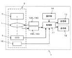
図1は、実施形態のカメラのブロック構成図である。
図2は、実施形態のカメラの断面図である。
図3は、図2のIII−III部矢視断面図である。
図4は、図3のIV−IV部矢視断面図である。[Embodiment]
Embodiments of a shake correction apparatus and a camera to which the present invention is applied will be described below.
FIG. 1 is a block diagram of a camera according to the embodiment.
FIG. 2 is a cross-sectional view of the camera of the embodiment.
3 is a cross-sectional view taken along the line III-III in FIG.
4 is a cross-sectional view taken along the line IV-IV in FIG.
図1に本実施形態のカメラ1の構成をブロック図で示す。レンズ鏡筒2は屈曲部であるプリズムP、レンズL、CCD3などから構成される。不図示の被写体からの光は、レンズ鏡筒に入射後プリズムPで90度偏向された後、レンズLによってCCD3に結像される。レンズ鏡筒2の詳細については図2を用いて後で詳しく説明する。 FIG. 1 is a block diagram showing the configuration of the
CCD3に入射した光は、電気信号に変換され制御部11に画像信号として送られる。制御部11は、ASICなどから構成されCCD3からの画像信号を処理する。制御部11で処理され、必要に応じてJPEGファイルなどに変換された画像データは、記憶部13に保存される。また、制御部11で処理された画像データは、カメラに装備されている液晶ディスプレイなどの表示部12に表示される。 The light incident on the
操作部14は、撮影ボタン、ズームボタン、各種撮影状態を設定するための十字ボタンなどから構成される。例えば操作部14の撮影ボタンが撮影者によって押されると、制御部4は不図示のシャッタを開閉し、所定時間CCD3を露光させて被写体像を撮像する。またズームボタンが操作されると、制御部11は不図示のモータを駆動してレンズL中のズームレンズを移動させ、CCD3に結像される被写体像の倍率を変化させる。 The
ボイスコイルモータ(VCM)130、140はブレを補正するために、レンズL中のブレ補正レンズ群を移動させる。ブレ補正レンズ群の動きは、位置検出器150、160で検出され、検出位置を基にVCM130、140で動かすブレ補正レンズ群の位置を補正する。VCM130、140、位置検出器150、160、ブレ補正レンズ群の動きについては後で詳しく説明する。 Voice coil motors (VCM) 130 and 140 move the blur correction lens group in the lens L in order to correct blur. The movement of the shake correction lens group is detected by the
ジャイロ15は撮影時のカメラ1の動き、すなわち手振れを検出するためのセンサである。ジャイロ15は2つの角速度センサから構成され、それぞれピッチング(上下方向の回転)、ヨーイング(左右方向の回転)を検出する。撮影ボタンが撮影者により押されると、ジャイロ15はカメラ1の傾き角度を検出し、その信号を制御部11に出力する。傾き角度を受け取った制御部11は、位置検出器150、160でブレ補正レンズ群の位置を検出し、ジャイロ15で検出した傾き角度を基に手振れを補正するために必要なブレ補正レンズ群の移動量を算出し、VCM130、140を制御する信号を出力する。VCM130、140はこの信号に基づいてブレ補正レンズ群を移動させる。これにより撮影時に手振れが発生しても、ブレ補正レンズ群がそれを打ち消すように移動するため、撮影した画像にはブレは発生しない。 The
次に図2を参照しながらレンズ鏡筒2について説明する。
図2に示すように、レンズ鏡筒2は、対物側から順に、第1レンズ群L1、プリズムP、第2レンズ群L2、第3レンズ群L3、ブレ補正レンズ群(第4レンズ群)L4、第5レンズ群L5を配列して構成された撮像光学系を備えている。
また、レンズ鏡筒2は、CCD3、ローパスフィルタ4、シャッタ絞りユニット5を備えている。Next, the
As shown in FIG. 2, the
The
第1レンズ群L1は、撮像光学系のうち最も対物側に設けられた対物レンズである。
プリズムPは、第1レンズ群L1が射出した被写体の光を全反射させてその進行方向を90度曲げる直角プリズムである。
以下、この撮像光学系におけるプリズムPの入射側の光軸、射出側の光軸に、それぞれ符号A1、A2を付して説明する。
光軸A2は、通常撮影時において、プリズムPに対して鉛直方向に配置され、第2レンズ群L2よりも像側の各レンズ群は、プリズムPに対して下側に順次配列されている。
ここで、本明細書において「通常撮影時」とは、対物側の光軸A1を略水平とし、表示部12の長辺方向を略水平としたカメラの姿勢を指すものとする。The first lens unit L1 is an objective lens provided on the most object side in the imaging optical system.
The prism P is a right-angle prism that totally reflects the light of the subject emitted by the first lens unit L1 and bends its traveling direction by 90 degrees.
Hereinafter, the optical axis on the incident side and the optical axis on the exit side of the prism P in this imaging optical system will be described with reference numerals A1 and A2, respectively.
The optical axis A2 is arranged in the vertical direction with respect to the prism P during normal photographing, and the lens groups on the image side with respect to the second lens group L2 are sequentially arranged below the prism P.
In this specification, “during normal shooting” refers to the posture of the camera in which the optical axis A1 on the objective side is substantially horizontal and the long side direction of the
第2レンズ群L2は、プリズムPの射出側に設けられている。第2レンズ群L2は、プリズムPに対する位置が固定されている。
第3レンズ群L3は、第2レンズ群L2の射出側に設けられ、光軸A2上での位置が固定されている。また、第3レンズ群L3は、図示しないレンズ駆動モータによって、光軸A2上を移動する。The second lens group L2 is provided on the exit side of the prism P. The position of the second lens group L2 with respect to the prism P is fixed.
The third lens group L3 is provided on the exit side of the second lens group L2, and its position on the optical axis A2 is fixed. The third lens unit L3 moves on the optical axis A2 by a lens driving motor (not shown).
ブレ補正レンズ群(第4レンズ群)L4は、第3レンズ群L3の射出側に設けられ、ブレ補正装置100の一部を構成するものである。このブレ補正装置100の構成、機能については後に詳しく説明する。ブレ補正レンズ群L4は、他のレンズ群に対して、光軸A2と直交する面内でシフト変位することによって、カメラの動きに起因する像ブレを低減するものである。
第5レンズ群L5は、ブレ補正レンズ群L4の射出側に設けられ、光軸A2上の位置が固定されている。また、第5レンズ群L5は、図示しないレンズ駆動モータによって、光軸A上を移動する。The blur correction lens group (fourth lens group) L4 is provided on the exit side of the third lens group L3 and constitutes a part of the
The fifth lens unit L5 is provided on the exit side of the blur correction lens unit L4, and the position on the optical axis A2 is fixed. The fifth lens unit L5 moves on the optical axis A by a lens drive motor (not shown).
CCD3は、第5レンズ群L5の射出側に設けられた固体撮像素子である。CCD3は、撮像光学系が撮像面上に結像する被写体像の光に基づいて、電気的な画像出力信号を生成するものである。
ローパスフィルタ(LPF)4は、第5レンズ群L5とCCD3との間に設けられ、CCD3が出力する画像出力信号におけるモアレの発生を防止するものである。
シャッタ絞りユニット5は、ブレ補正レンズ群L4の入射側に設けられ、撮像光学系を通過する像光の光量を規制する絞り部と、像光がCCD3に露光する露光時間を調整するシャッタ部とを備えている。The
The low-pass filter (LPF) 4 is provided between the fifth lens unit L5 and the
The
また、レンズ鏡筒2は、以下説明するブレ補正装置100を備えている。
ブレ補正装置100は、図3及び図4に示すように、固定枠110、振動枠120、ボイスコイルモータ130,140、位置検出器150,160、鋼球170を備えている。The
As shown in FIGS. 3 and 4, the
固定枠110は、光軸A2に対するその位置が固定された枠体である。
振動枠120は、固定枠110に対して、光軸A2に直交する面内で移動可能に支持されている。また、振動枠120には、上述したブレ補正レンズ群L4がその中央部に固定されている。
図3に示すように、固定枠110及び振動枠120は、光軸A2方向から見ると、光軸A1と平行な方向(図3におけるY方向)の寸法よりも、光軸A1及び光軸A2に直交する方向(図3におけるX方向)の寸法のほうが大きい略矩形状に形成されている。
また、固定枠110及び振動枠120の対物側の長辺部には、被写体側へ張り出した凸部111,121がそれぞれ設けられている。The fixed
The
As shown in FIG. 3, the fixed
Further,
ボイスコイルモータ(VCM)130,140は、振動枠120を固定枠110に対して、光軸A2と直交する面内において駆動する電磁アクチュエータである。VCM130は、ジャイロ15によって検出されたカメラ1の傾き角に応じて、振動枠120を駆動し像ブレを低減する公知のブレ補正制御に用いられるものである。
VCM130,140は、図3に示すように、固定枠110及び振動枠120の長手方向(X方向)に離間して配置され、その駆動方向(推力方向)D1,D2は、長手方向に対して45°傾斜している。また、VCM130,140の駆動方向D1,D2は、相互に直交するように配置されている。配置は、振動枠120が固定枠110に対してセンタリングされた状態を基準として説明する。ここで、振動枠120がセンタリングされた状態とは、ブレ補正レンズ群L4の光軸が、他のレンズ群の光軸A2と実質的に一致した状態を指すものとする。The voice coil motors (VCM) 130 and 140 are electromagnetic actuators that drive the
As shown in FIG. 3, the
ここでブレ補正レンズ群L4とVCM130、140の配置について説明する。VCM130、140の形状は、駆動方向D1、D2の寸法よりもそれに直交する方向の寸法が長くなっている。2つのVCM130、140は、図3に示すようにY方向に平行でブレ補正レンズ群L4の光軸を通る線ALに対して線対称の位置に、対物側に向かってハの字状に配置されている。 Here, the arrangement of the blur correction lens unit L4 and the
ブレ補正レンズ群L4は、その光軸がVCM130とVCM140の問の領域に位置するように配置されている。なおVCM130とVCM140の間とは、VCM130の最も撮影者側の点V3とVCM140の最も撮影者側の点V4を結ぶ線、VCM130の最も対物側の点V5とVCM140の最も対物側の点V6を結ぶ線、およびVCM130、VCM140で囲まれた領域を言う。なおブレ補正レンズ群L4は、VCM130とVCM140の間の領域に、少なくともその一部が入るように配置しても構わない。 The blur correction lens unit L4 is arranged so that its optical axis is located in the question area between the
またVCM130の中心V1を通り駆動方向D1に平行な線を第1駆動中心線TL1、VCM140の中心V2を通り駆動方向D2に平行な線を第2駆動中心線TL2とすると、ブレ補正レンズ群L4はその光軸が第1駆動中心線TL1と第2駆動中心線TL2の交点からY軸方向に所定距離離れた位置になるように配置されている。なおY軸方向以外の方向に所定距離離れていても構わない。 Further, assuming that a line passing through the center V1 of the
またVCM130の中心を通りその長手方向に平行な線を第1中心線、VCM140の中心を通りその長手方向に平行な線を第2中心線とすると、ブレ補正レンズ群L4はその光軸が第1中心線と第2中心線の交点からY軸方向に所定距離離れた位置になるように配置しても構わない。なおY軸方向以外の方向に所定距離離れていても構わない。 Further, if the line passing through the center of the
VCM130は、図4に示すように、コイル131、マグネット132、ヨーク133,134を備えている。
コイル131は、振動枠120に対向した状態で固定枠110に固定された電気子巻線である。また、コイル131は、図3に示すように、駆動方向と直交する方向を長軸とする長円状に形成されている。
マグネット132は、コイル131に対向した状態で振動枠120に固定された永久磁石である。
ヨーク133,134は、例えば鉄系金属等によってプレート状に形成された磁性体である。
ヨーク133は、コイル131のマグネット132とは反対側の面に配置されている。
ヨーク134は、マグネット132のコイル131とは反対側の面に配置されている。
なお、VCM140も上述したVCM130と同様の構造を備えている。As shown in FIG. 4, the
The
The
The
The
The
The
位置検出器150,160は、光軸A2と直交する面内における振動枠120の固定枠110に対する位置を検出する位置センサである。
位置検出器150は、図3に示すように、その検出方向D3が上述したVCM140の駆動方向D2と平行となっている。この位置検出器150は、光軸A2を通りかつ検出方向D3と平行な直線上に配置されている。
位置検出器160は、その検出方向D4が上述したVCM130の駆動方向D1と平行となっている。この位置検出器160は、光軸A2を通りかつ検出方向D4と平行な直線上に配置されている。
従って、位置検出器150,160のそれぞれの検出方向は、ブレ補正レンズ群L4の光軸(振動枠120がセンタリングされている場合)において交わるようになっている。The
As shown in FIG. 3, the
The detection direction D4 of the
Therefore, the detection directions of the
また、位置検出器150,160は、固定枠110及び振動枠120の対物側の端部付近に設けられ、その一部は、上述した凸部111,121内に配置されている。
さらに、位置検出器150,160は、その一部が、X方向においてVCM130,140によって挟まれた領域内に配置されている。
また、少なくともその一部をVCM130、140の間に配置しても構わない。The
Further, part of the
Further, at least a part of them may be arranged between the
位置検出器150は、図4に示すように、マグネット151、ホール素子152、ヨーク153,154を備えている。
マグネット151は、固定枠110に対向した状態で振動枠120に固定された永久磁石である。
ホール素子152は、マグネット151に対向した状態で固定枠110に固定された磁気センサである。このホール素子152は、振動枠120の固定枠110に対する変位に応じたマグネット151の磁界の変化を検出するものである。
ヨーク153は、マグネット151のホール素子152とは反対側の面に配置されている。
ヨーク154は、ホール素子152のマグネット151とは反対側の面に配置されている。
なお、位置検出器160も上述した位置検出器150と同様の構造を備えている。As shown in FIG. 4, the
The
The
The
The
The
鋼球170は、固定枠110と振動枠120との間に挟持され、振動枠120を固定枠110に対して、光軸A2と直交する面内において相対移動可能に支持する転動体である。
図4に示すように、固定枠110の振動枠120と対向する面には、カップ状に窪んだ凹部112が設けられている。凹部112の底面は、光軸A2と直交する平面と平行であり、平滑に形成されている。また、振動枠120には、固定枠110の凹部112と対向する面から突き出した凸部122が設けられている。凸部122の凹部112と対向する面は、光軸A2と直交する平面と平行であり、平滑に形成されている。
鋼球170は、凹部112の底面と、これに対向する凸部122の面との間に挟まれた状態となっている。The
As shown in FIG. 4, a
The
図3に示すように、鋼球170は、例えば3つ設けられている。鋼球170のうち1つ(符号170aを付して図示する)は、固定枠110、振動枠120のそれぞれの凸部111,121内の位置検出器150,160に挟まれた領域に配置されている。
また、鋼球170のうち他の2つ(それぞれ符号170b,170cを付して図示する)は、ブレ補正装置100の撮影者側(対物側と反対側)の端部であって、固定枠110、振動枠120の長手方向(X方向)の両端部にそれぞれ配置されている。
そして、VCM130は、鋼球170a,170bの間に配置され、VCM140は、鋼球170a,170cの間に配置されている。As shown in FIG. 3, for example, three
The other two of the steel balls 170 (shown with
The
以上説明した本実施形態によれば、以下の効果を得ることができる。
(1)VCM130,140を、その推力中心線TL1,TL2が振動枠120の長手方向に対してそれぞれ45°傾斜させるとともに、これらの交点Oが光軸A2に対してオフセットするように配置することによって、ブレ補正レンズ群L4を、振動枠120の長手方向においてVCM130,140によって挟まれた領域内に配置することができ、これによって、ブレ補正装置100の振動枠120の長手方向と直交する方向の寸法を小さくすることが可能になり、カメラ1の薄型化を図ることができる。
(2)位置検出器150,160を、その検出方向の交点がブレ補正レンズ群L4の中心と略一致するように配置したことによって、各位置検出器150,160の検出精度を確保することができる。
(3)位置検出器150,160を、振動枠120の長手方向においてVCM130,140に挟まれた領域内に配置することによって、ブレ補正装置100をよりコンパクトにすることができる。さらに、位置検出器150,160を、ブレ補正装置100の対物側の端部に配置しているから、位置検出器150,160を収容するために固定枠110、振動枠120に凸部111,121を形成しても、これらを第1レンズ群L1等の下側に配置することによって、カメラ1全体をコンパクト化するうえで妨げとなりにくい。
(4)VCM130,140を、それぞれ1対の鋼球170に挟まれた状態で配置することによって、固定枠110、振動枠120の曲げ変形等が生じにくく、ブレ補正レンズ群L4の支持精度を確保することができる。According to this embodiment described above, the following effects can be obtained.
(1) The
(2) By arranging the
(3) By arranging the
(4) By arranging the
(変形例)
本発明は、以上説明した実施形態に限定されることなく、種々の変形や変更が可能であって、それらも本発明の均等の範囲内である。
(1)実施形態は、ブレ補正レンズ群をシフト駆動してブレ補正を行うものであったが、本発明はこれに限らず、例えば、撮像素子を光軸と交わる方向にシフト駆動するものにも適用することができる。その場合ブレ補正レンズ群の光軸は、撮像素子の中心に対応する。
(2)実施形態は、屈曲光学系を有するデジタルスチルカメラに係るものであったが、本発明はこれに限らず、屈曲部を持たない通常の光学系を備えたカメラにも適用することができ、例えば、レンズ鏡筒部分が他の部分に対して回転可能に装着されたいわゆるスイバル式のカメラであっても、その薄型化を図るうえで有用である。また、本発明は、レンズ交換式カメラシステムのレンズ鏡筒や、携帯電話機等に内蔵されるカメラ等にも適用することができる。
(3)実施形態は、2つの駆動部の駆動方向がそれぞれ振動枠等の長手方向に対して傾斜したものであったが、本発明はこれに限らず、適宜変更することができる。例えば、振動枠の長手方向を駆動方向とする第1の駆動部と、これに対する直交方向を駆動方向とする第2の駆動部とを振動枠の長手方向に沿って配列し、その中間部にブレ補正光学系等を配置した構成としてもよい。この場合であっても、ブレ補正装置の一方向の寸法を小さくし、カメラを薄型化することができる。
(4)実施形態においては、一対の駆動部の駆動方向と一対の位置検出部の検出方向がそれぞれ一致しているが、これに限らず、駆動部の駆動方向と位置検出部の検出方向とがずれていてもよい。また、実施形態においては、一対の駆動部の2つの駆動方向、一対の位置検出部の2つの検出方向は、それぞれ直交しているが、必ずしもこれらは直交していなくてもよい。
(5)実施形態は、駆動部としてボイスコイルモータを用いるものであったが、本発明はこれに限らず、他のアクチュエータを駆動部としたものであってもよい。例えば、ピエゾ素子やステッピングモータを用いて振動枠を駆動するようにしてもよい。(Modification)
The present invention is not limited to the embodiments described above, and various modifications and changes are possible, and these are also within the equivalent scope of the present invention.
(1) In the embodiment, the blur correction lens group is shift-driven to perform the blur correction. However, the present invention is not limited to this. For example, the image sensor is shift-driven in a direction crossing the optical axis. Can also be applied. In that case, the optical axis of the blur correction lens group corresponds to the center of the image sensor.
(2) The embodiment relates to a digital still camera having a bent optical system, but the present invention is not limited to this, and may be applied to a camera having a normal optical system having no bent portion. For example, even a so-called swivel camera in which a lens barrel portion is rotatably attached to another portion is useful in reducing the thickness thereof. The present invention can also be applied to a lens barrel of an interchangeable lens camera system, a camera built in a mobile phone or the like.
(3) In the embodiment, the drive directions of the two drive units are inclined with respect to the longitudinal direction of the vibration frame or the like, but the present invention is not limited to this, and can be changed as appropriate. For example, a first drive unit having a drive direction that is the longitudinal direction of the vibration frame and a second drive unit having a drive direction that is orthogonal to the first drive unit are arranged along the longitudinal direction of the vibration frame, A configuration in which a shake correction optical system or the like is arranged may be employed. Even in this case, it is possible to reduce the size of the camera in one direction and reduce the thickness of the camera.
(4) In the embodiment, the drive direction of the pair of drive units and the detection direction of the pair of position detection units are the same, but not limited thereto, the drive direction of the drive unit and the detection direction of the position detection unit May be off. In the embodiment, the two drive directions of the pair of drive units and the two detection directions of the pair of position detection units are orthogonal to each other, but they are not necessarily orthogonal.
(5) In the embodiment, a voice coil motor is used as the drive unit. However, the present invention is not limited to this, and another actuator may be used as the drive unit. For example, the vibration frame may be driven using a piezo element or a stepping motor.
1:カメラ、2:レンズ鏡筒、100:ブレ補正装置、110:固定枠、120:振動枠、130,140:VCM、150,160:位置検出器、170:鋼球
L4:ブレ補正レンズ群
A1,A2:光軸
D1,D2:VCMの駆動方向、D3,D4:位置検出器の検出方向
1: camera, 2: lens barrel, 100: shake correction device, 110: fixed frame, 120: vibration frame, 130, 140: VCM, 150, 160: position detector, 170: steel ball L4: shake correction lens group A1, A2: Optical axes D1, D2: VCM drive direction, D3, D4: Detection direction of position detector
Claims (11)
Translated fromJapanese前記ブレ補正光学系を保持し、前記光学系の光軸と垂直な面内で移動可能な移動部材と、
前記移動部材を第1方向に移動させる第1駆動素子と、
前記移動部材を第1方向とは異なる第2方向に移動させる第2駆動素子とを有し、
前記ブレ補正光学系の光軸は、前記第1駆動素子と前記第2駆動素子との間に配置され、
前記第1駆動素子及び第2駆動素子は、前記第1駆動素子の中心を通り前記第1方向に平行な第1駆動中心線と前記第2駆動素子の中心を通り前記第2方向に平行な第2駆動中心線との交点が前記ブレ補正光学系の外形よりも外側に位置するように配置されていること
を特徴とするブレ補正装置。An optical system equipped with a blur correction optical system;
A movable member that holds the blur correction optical system and is movable in a plane perpendicular to the optical axis of the optical system;
A first drive element for moving the moving member in a first direction;
A second drive element that moves the moving member in a second direction different from the first direction;
The optical axis of the blur correction optical system is disposed between the first drive element and the second drive element,
The first driving element and the second driving element pass through the center of the first driving element and are parallel to the first direction and through the center of the second driving element and parallel to the second direction. The blur correction device, wherein the intersection with the second drive center line is arranged outside the outer shape of the blur correction optical system.
前記ブレ補正光学系を保持し、前記光学系の光軸と垂直な面内で移動可能な移動部材と、
前記移動部材を第1方向に移動させる第1駆動素子と、
前記移動部材を第1方向とは異なる第2方向に移動させる第2駆動素子とを有し、
前記ブレ補正光学系の光軸は、前記第1駆動素子と前記第2駆動素子との間に配置され、
前記第1駆動素子及び第2駆動素子は、前記第1駆動素子の中心を通り前記第1駆動素子の長手方向に平行な第1中心線と前記第2駆動素子の中心を通り前記第2駆動素子の長手方向に平行な第2中心線との交点が前記ブレ補正光学系の外形よりも外側に位置するように配置されていること
を特徴とするブレ補正装置。An optical system equipped with a blur correction optical system;
A movable member that holds the blur correction optical system and is movable in a plane perpendicular to the optical axis of the optical system;
A first drive element for moving the moving member in a first direction;
A second drive element that moves the moving member in a second direction different from the first direction;
The optical axis of the blur correction optical system is disposed between the first drive element and the second drive element,
The first drive element and the second drive element pass through the center of the first drive element and pass through the center of the first drive element and the first center line parallel to the longitudinal direction of the first drive element and the second drive element. A blur correction device, wherein an intersection with a second center line parallel to the longitudinal direction of the element is located outside the outer shape of the blur correction optical system.
を特徴とする請求項1または2に記載のブレ補正装置。Wherein the first drive element second driving element,claims, characterized inthat it is arranged in line symmetry with respect to a predetermined line passing through the optical axis in a plane perpendicular to the optical axis of the optical systemThe blur correction device accordingto 1 or 2 .
を特徴とする請求項3に記載のブレ補正装置。The blur correction apparatus according toclaim 3,wherein the longitudinal direction of the first driving element and the longitudinal direction of the second driving element areinclined 45 degrees in opposite directions with respect to the predetermined line .
を特徴とする請求項4に記載のブレ補正装置。The blur correction apparatus according to claim4, wherein a driving direction of the first driving element anda driving direction of the second driving element areinclined by45 degrees with respect to the predetermined line .
を特徴とする請求項1〜請求項5のいずれか一項に記載のブレ補正装置。The blur correction device accordingto claim 1, further comprising: a fixed member that has an opening that allows the light beam of the optical system to pass therethrough and that supports the moving member in a movable manner. .
を特徴とする請求項6に記載のブレ補正装置。The said 1st drive elementand the said 2nd drive element are voice coil motors, The member which comprises the said voice coil motor is arrange | positioned at the said moving member and the said fixed member. The image stabilization apparatus described.
を特徴とする請求項1〜7のいずれか一項に記載のブレ補正装置。The shake correction apparatus according to claim 1, furthercomprising a position detection element that detects a position of the shake correction optical system .
前記ブレ補正光学系の光軸は、前記第1位置検出素子の中心を通り前記第1方向に平行な第1検出中心線と前記第2位置検出素子の中心を通り前記第2方向に平行な第2検出中心線との交点と一致していること
を特徴とする請求項8に記載のブレ補正装置。The position detection element includes a first position detection element that detects a position in the first direction and a second position detection element that detects a position in the second direction,
The optical axis of the blur correction optical system passes through the center of the first position detection element and is parallel to the first direction, and passes through the center of the second position detection element and is parallel to the second direction. The blur correction device according to claim 8, wherein the blur correction devicematches an intersection with the second detection center line .
を特徴とする請求項9に記載のブレ補正装置。The blur correction apparatus according to claim9, wherein at least a part of the first position detection element or the second detection element is disposed between the first drive element and the second drive element. .
を特徴とするカメラ。Camera characterized by.
Priority Applications (5)
| Application Number | Priority Date | Filing Date | Title |
|---|---|---|---|
| JP2006061132AJP4844177B2 (en) | 2006-03-07 | 2006-03-07 | Blur correction device and camera |
| EP15191766.3AEP3001239A1 (en) | 2006-03-07 | 2007-03-06 | Vibration reduction device and camera |
| EP07103623.0AEP1832912B1 (en) | 2006-03-07 | 2007-03-06 | Image blur reduction device and camera |
| EP10185561.7AEP2267512B1 (en) | 2006-03-07 | 2007-03-06 | Image blur reduction device and camera |
| US11/714,138US8295694B2 (en) | 2006-03-07 | 2007-03-06 | Vibration reduction device and camera |
Applications Claiming Priority (1)
| Application Number | Priority Date | Filing Date | Title |
|---|---|---|---|
| JP2006061132AJP4844177B2 (en) | 2006-03-07 | 2006-03-07 | Blur correction device and camera |
Publications (2)
| Publication Number | Publication Date |
|---|---|
| JP2007240736A JP2007240736A (en) | 2007-09-20 |
| JP4844177B2true JP4844177B2 (en) | 2011-12-28 |
Family
ID=38077202
Family Applications (1)
| Application Number | Title | Priority Date | Filing Date |
|---|---|---|---|
| JP2006061132AActiveJP4844177B2 (en) | 2006-03-07 | 2006-03-07 | Blur correction device and camera |
Country Status (3)
| Country | Link |
|---|---|
| US (1) | US8295694B2 (en) |
| EP (3) | EP3001239A1 (en) |
| JP (1) | JP4844177B2 (en) |
Families Citing this family (33)
| Publication number | Priority date | Publication date | Assignee | Title |
|---|---|---|---|---|
| JP5003008B2 (en)* | 2006-04-17 | 2012-08-15 | コニカミノルタアドバンストレイヤー株式会社 | Camera shake correction device, lens unit, and imaging device |
| KR101404843B1 (en)* | 2006-06-22 | 2014-06-09 | 가부시키가이샤 니콘 | Positioning Apparatus, Shake Correction Device, and Electronic Apparatus |
| JP5109450B2 (en)* | 2007-04-09 | 2012-12-26 | 株式会社ニコン | Blur correction device and optical apparatus |
| US20080297901A1 (en)* | 2007-05-29 | 2008-12-04 | Nikon Corporation | Zoom lens system, optical apparatus, and method for forming an image |
| KR101378212B1 (en)* | 2007-07-20 | 2014-04-14 | 삼성전자주식회사 | Apparatus and method for vibration noise reduction on mobile camera module |
| JP2009069588A (en)* | 2007-09-14 | 2009-04-02 | Konica Minolta Opto Inc | Optical unit and imaging apparatus |
| JP4991497B2 (en)* | 2007-11-28 | 2012-08-01 | 三星電子株式会社 | Image blur correction device |
| US8159540B2 (en)* | 2007-11-28 | 2012-04-17 | Semiconductor Components Industries, Llc | Semiconductor device and imaging capturing apparatus |
| WO2009093635A1 (en)* | 2008-01-22 | 2009-07-30 | Nikon Corporation | Lens tube, method of adjusting lens tube, method of manufacturing lens tube and imaging device |
| CN102165367B (en)* | 2008-09-29 | 2014-02-12 | 日本电产科宝株式会社 | Image Shake Correction Device, Imaging Lens Unit, and Camera Unit |
| GB0918453D0 (en) | 2009-10-21 | 2009-12-09 | Selexsensors And Airborne Syst | Imaging device |
| JP5269143B2 (en)* | 2010-07-16 | 2013-08-21 | キヤノン株式会社 | Image blur correction apparatus, control method therefor, and imaging apparatus |
| US9485495B2 (en) | 2010-08-09 | 2016-11-01 | Qualcomm Incorporated | Autofocus for stereo images |
| US9172856B2 (en)* | 2011-03-29 | 2015-10-27 | Microsoft Technology Licensing, Llc | Folded imaging path camera |
| US9438889B2 (en) | 2011-09-21 | 2016-09-06 | Qualcomm Incorporated | System and method for improving methods of manufacturing stereoscopic image sensors |
| US9398264B2 (en) | 2012-10-19 | 2016-07-19 | Qualcomm Incorporated | Multi-camera system using folded optics |
| US10178373B2 (en) | 2013-08-16 | 2019-01-08 | Qualcomm Incorporated | Stereo yaw correction using autofocus feedback |
| US9374516B2 (en) | 2014-04-04 | 2016-06-21 | Qualcomm Incorporated | Auto-focus in low-profile folded optics multi-camera system |
| US9383550B2 (en) | 2014-04-04 | 2016-07-05 | Qualcomm Incorporated | Auto-focus in low-profile folded optics multi-camera system |
| US10013764B2 (en) | 2014-06-19 | 2018-07-03 | Qualcomm Incorporated | Local adaptive histogram equalization |
| US9294672B2 (en) | 2014-06-20 | 2016-03-22 | Qualcomm Incorporated | Multi-camera system using folded optics free from parallax and tilt artifacts |
| US9819863B2 (en) | 2014-06-20 | 2017-11-14 | Qualcomm Incorporated | Wide field of view array camera for hemispheric and spherical imaging |
| US9386222B2 (en) | 2014-06-20 | 2016-07-05 | Qualcomm Incorporated | Multi-camera system using folded optics free from parallax artifacts |
| US9549107B2 (en) | 2014-06-20 | 2017-01-17 | Qualcomm Incorporated | Autofocus for folded optic array cameras |
| US9541740B2 (en) | 2014-06-20 | 2017-01-10 | Qualcomm Incorporated | Folded optic array camera using refractive prisms |
| US9509891B2 (en) | 2014-10-21 | 2016-11-29 | Microsoft Technology Licensing, Llc | Controlling focus lens assembly |
| US9832381B2 (en) | 2014-10-31 | 2017-11-28 | Qualcomm Incorporated | Optical image stabilization for thin cameras |
| JP6611498B2 (en)* | 2015-07-17 | 2019-11-27 | オリンパス株式会社 | Vibration correction device |
| KR20240051317A (en)* | 2016-07-07 | 2024-04-19 | 코어포토닉스 리미티드 | Linear ball guided voice coil motor for folded optic |
| CN108333791B (en)* | 2018-04-28 | 2023-07-14 | 江西星星科技股份有限公司 | Anti-shake structure of camera |
| KR102258604B1 (en)* | 2019-09-10 | 2021-05-31 | 삼성전기주식회사 | Optical imaging system |
| US20220091398A1 (en)* | 2020-09-24 | 2022-03-24 | Apple Inc. | Telephoto Camera with a Stationary Optics Assembly |
| JP2024085477A (en)* | 2022-12-15 | 2024-06-27 | キヤノン株式会社 | Optical vibration isolation device and optical equipment |
Family Cites Families (37)
| Publication number | Priority date | Publication date | Assignee | Title |
|---|---|---|---|---|
| JPH0281009A (en)* | 1988-09-19 | 1990-03-22 | Canon Inc | Supporting structure for optical element holding frame |
| US5266988A (en) | 1989-12-18 | 1993-11-30 | Canon Kabushiki Kaisha | Image shake suppressing device for camera |
| JP3661229B2 (en)* | 1994-06-28 | 2005-06-15 | 株式会社ニコン | Anti-vibration camera |
| US5854947A (en) | 1996-06-18 | 1998-12-29 | Nikon Corporation | Vibration reducing apparatus |
| JP3713818B2 (en) | 1996-06-18 | 2005-11-09 | 株式会社ニコン | Image blur correction device |
| JPH103101A (en) | 1996-06-18 | 1998-01-06 | Nikon Corp | Image stabilizer |
| JP3858308B2 (en) | 1996-09-10 | 2006-12-13 | 株式会社ニコン | Blur correction device, lens barrel having blur correction device, and camera having blur correction device |
| JPH10186431A (en) | 1996-12-26 | 1998-07-14 | Nikon Corp | Image stabilizer |
| JPH10228044A (en) | 1997-02-17 | 1998-08-25 | Nikon Corp | Image stabilizer and switching device |
| JP3864483B2 (en) | 1997-03-11 | 2006-12-27 | 株式会社ニコン | Lens barrel |
| US5926656A (en) | 1997-03-11 | 1999-07-20 | Nikon Corporation | Vibration reducing apparatus and lens barrel |
| JP3809691B2 (en) | 1997-03-11 | 2006-08-16 | 株式会社ニコン | Blur correction device and lens barrel |
| US5905917A (en) | 1997-03-14 | 1999-05-18 | Nikon Corporation | Vibration reduction device |
| JPH10254016A (en) | 1997-03-14 | 1998-09-25 | Nikon Corp | Image stabilizer |
| JPH10254009A (en) | 1997-03-14 | 1998-09-25 | Nikon Corp | Image stabilizer |
| US6154611A (en)* | 1998-05-18 | 2000-11-28 | Canon Kabushiki Kaisha | Image-shake compensation apparatus |
| JP2000330153A (en)* | 1999-05-19 | 2000-11-30 | Canon Inc | Image stabilization device |
| JP2001201777A (en) | 2000-01-14 | 2001-07-27 | Minolta Co Ltd | Shake correcting device and optical equipment including the same |
| JP3969927B2 (en) | 2000-04-06 | 2007-09-05 | キヤノン株式会社 | Lens barrel, photographing device, and observation device |
| JP2001305434A (en) | 2000-04-18 | 2001-10-31 | Asahi Optical Co Ltd | Image stabilization device |
| JP3551932B2 (en)* | 2001-03-30 | 2004-08-11 | ミノルタ株式会社 | Distance measuring device and imaging device using the same |
| JP2003057707A (en) | 2001-08-08 | 2003-02-26 | Matsushita Electric Ind Co Ltd | Image stabilizer |
| JP2003075881A (en) | 2001-08-31 | 2003-03-12 | Pentax Corp | Image stabilization device |
| JP3907451B2 (en)* | 2001-11-19 | 2007-04-18 | 松下電器産業株式会社 | Image blur correction apparatus and manufacturing method thereof |
| JP2003255422A (en) | 2002-03-04 | 2003-09-10 | Canon Inc | Correction optical system vibration device |
| JP2003322889A (en)* | 2002-05-07 | 2003-11-14 | Sigma Corp | Camera shake compensation device |
| JP4253177B2 (en)* | 2002-11-26 | 2009-04-08 | 株式会社シグマ | Image shake prevention device |
| JP2005077886A (en)* | 2003-09-02 | 2005-03-24 | Canon Inc | Imaging device |
| JP2005084655A (en) | 2003-09-11 | 2005-03-31 | Olympus Corp | Lens housing for bending optical system |
| JP2005217993A (en)* | 2004-01-30 | 2005-08-11 | Canon Inc | Imaging device |
| JP2005221603A (en) | 2004-02-04 | 2005-08-18 | Matsushita Electric Ind Co Ltd | Image blur correction device |
| US7742076B2 (en)* | 2004-05-25 | 2010-06-22 | Hoya Corporation | Image-capturing apparatus and camera-shake compensation mechanism |
| JP2005352125A (en) | 2004-06-10 | 2005-12-22 | Nikon Corp | Blur correction device |
| US7710459B2 (en)* | 2004-07-21 | 2010-05-04 | Hewlett-Packard Development Company, L.P. | Ferrofluid suspension for image stabilization |
| JP2006243701A (en) | 2005-02-07 | 2006-09-14 | Fuji Photo Film Co Ltd | Camera and lens system |
| JP2006267752A (en)* | 2005-03-25 | 2006-10-05 | Canon Inc | Image blur correction apparatus and optical apparatus |
| JP4789655B2 (en)* | 2006-03-03 | 2011-10-12 | キヤノン株式会社 | Vibration correction device, lens barrel, and optical device |
- 2006
- 2006-03-07JPJP2006061132Apatent/JP4844177B2/enactiveActive
- 2007
- 2007-03-06EPEP15191766.3Apatent/EP3001239A1/ennot_activeWithdrawn
- 2007-03-06USUS11/714,138patent/US8295694B2/enactiveActive
- 2007-03-06EPEP07103623.0Apatent/EP1832912B1/enactiveActive
- 2007-03-06EPEP10185561.7Apatent/EP2267512B1/enactiveActive
Also Published As
| Publication number | Publication date |
|---|---|
| EP2267512B1 (en) | 2013-11-06 |
| US8295694B2 (en) | 2012-10-23 |
| EP2267512A3 (en) | 2011-05-18 |
| EP1832912B1 (en) | 2015-12-23 |
| EP1832912A3 (en) | 2007-10-31 |
| EP3001239A1 (en) | 2016-03-30 |
| US20070212046A1 (en) | 2007-09-13 |
| EP2267512A2 (en) | 2010-12-29 |
| JP2007240736A (en) | 2007-09-20 |
| EP1832912A2 (en) | 2007-09-12 |
Similar Documents
| Publication | Publication Date | Title |
|---|---|---|
| JP4844177B2 (en) | Blur correction device and camera | |
| CN101995730B (en) | Optical element driving device and imaging device | |
| JP5109450B2 (en) | Blur correction device and optical apparatus | |
| JP4858068B2 (en) | Blur correction mechanism and optical device | |
| JP4227585B2 (en) | Lens barrel and imaging device provided with the same | |
| JP4661915B2 (en) | Image blur correction device, lens barrel device, and camera device | |
| JP4857006B2 (en) | Camera system | |
| JP5012085B2 (en) | Blur correction device and optical device | |
| EP2098901B1 (en) | Image blur correction unit, lens barrel device, and camera apparatus | |
| JP2008180774A (en) | Lens barrel and digital camera | |
| CN112394599A (en) | Optical unit | |
| KR20140027418A (en) | Imaging device | |
| JP4973219B2 (en) | Optical equipment | |
| JP2006259247A (en) | Image blur correction device | |
| JP5820667B2 (en) | Optical image stabilization mechanism | |
| JP2007171234A (en) | Image stabilization apparatus and method | |
| KR101464533B1 (en) | Camera shake compensation device | |
| JP5458521B2 (en) | Lens barrel, lens barrel adjustment method, optical device, and optical device adjustment method | |
| JP2008076612A (en) | Blur correction device and optical apparatus | |
| JP2009229551A (en) | Optical device and camera | |
| JP4618004B2 (en) | Imaging device | |
| JP2024036887A (en) | Optical unit with shake correction function | |
| JP2016033560A (en) | Optical apparatus having image blur correction device | |
| JP2014228622A (en) | Camera-shake correcting device, lens barrel, and photographing apparatus |
Legal Events
| Date | Code | Title | Description |
|---|---|---|---|
| A621 | Written request for application examination | Free format text:JAPANESE INTERMEDIATE CODE: A621 Effective date:20090210 | |
| A131 | Notification of reasons for refusal | Free format text:JAPANESE INTERMEDIATE CODE: A131 Effective date:20110215 | |
| A521 | Request for written amendment filed | Free format text:JAPANESE INTERMEDIATE CODE: A523 Effective date:20110418 | |
| A131 | Notification of reasons for refusal | Free format text:JAPANESE INTERMEDIATE CODE: A131 Effective date:20110607 | |
| A521 | Request for written amendment filed | Free format text:JAPANESE INTERMEDIATE CODE: A523 Effective date:20110805 | |
| TRDD | Decision of grant or rejection written | ||
| A01 | Written decision to grant a patent or to grant a registration (utility model) | Free format text:JAPANESE INTERMEDIATE CODE: A01 Effective date:20110913 | |
| A01 | Written decision to grant a patent or to grant a registration (utility model) | Free format text:JAPANESE INTERMEDIATE CODE: A01 | |
| A61 | First payment of annual fees (during grant procedure) | Free format text:JAPANESE INTERMEDIATE CODE: A61 Effective date:20110926 | |
| FPAY | Renewal fee payment (event date is renewal date of database) | Free format text:PAYMENT UNTIL: 20141021 Year of fee payment:3 | |
| R150 | Certificate of patent or registration of utility model | Free format text:JAPANESE INTERMEDIATE CODE: R150 Ref document number:4844177 Country of ref document:JP Free format text:JAPANESE INTERMEDIATE CODE: R150 | |
| FPAY | Renewal fee payment (event date is renewal date of database) | Free format text:PAYMENT UNTIL: 20141021 Year of fee payment:3 | |
| R250 | Receipt of annual fees | Free format text:JAPANESE INTERMEDIATE CODE: R250 | |
| R250 | Receipt of annual fees | Free format text:JAPANESE INTERMEDIATE CODE: R250 | |
| R250 | Receipt of annual fees | Free format text:JAPANESE INTERMEDIATE CODE: R250 | |
| R250 | Receipt of annual fees | Free format text:JAPANESE INTERMEDIATE CODE: R250 | |
| R250 | Receipt of annual fees | Free format text:JAPANESE INTERMEDIATE CODE: R250 | |
| R250 | Receipt of annual fees | Free format text:JAPANESE INTERMEDIATE CODE: R250 | |
| R250 | Receipt of annual fees | Free format text:JAPANESE INTERMEDIATE CODE: R250 | |
| R250 | Receipt of annual fees | Free format text:JAPANESE INTERMEDIATE CODE: R250 | |
| R250 | Receipt of annual fees | Free format text:JAPANESE INTERMEDIATE CODE: R250 | |
| R250 | Receipt of annual fees | Free format text:JAPANESE INTERMEDIATE CODE: R250 | |
| R250 | Receipt of annual fees | Free format text:JAPANESE INTERMEDIATE CODE: R250 | |
| R250 | Receipt of annual fees | Free format text:JAPANESE INTERMEDIATE CODE: R250 |