JP4844161B2 - Cell electrophysiological sensor, measuring method using the same, and manufacturing method thereof - Google Patents
Cell electrophysiological sensor, measuring method using the same, and manufacturing method thereofDownload PDFInfo
- Publication number
- JP4844161B2 JP4844161B2JP2006046548AJP2006046548AJP4844161B2JP 4844161 B2JP4844161 B2JP 4844161B2JP 2006046548 AJP2006046548 AJP 2006046548AJP 2006046548 AJP2006046548 AJP 2006046548AJP 4844161 B2JP4844161 B2JP 4844161B2
- Authority
- JP
- Japan
- Prior art keywords
- cell
- holding substrate
- recesses
- cell holding
- cells
- Prior art date
- Legal status (The legal status is an assumption and is not a legal conclusion. Google has not performed a legal analysis and makes no representation as to the accuracy of the status listed.)
- Expired - Fee Related
Links
Images


Landscapes
- Apparatus Associated With Microorganisms And Enzymes (AREA)
Description
Translated fromJapanese本発明は、細胞の細胞外電位あるいは細胞の活動に発生する物理化学的変化を測定するために用いられる細胞電気生理センサとそれを用いた測定方法およびその製造方法に関するものである。 The present invention relates to a cell electrophysiological sensor used for measuring a physicochemical change occurring in an extracellular potential of a cell or a cell activity, a measuring method using the same, and a manufacturing method thereof.
従来の、細胞の電気的活動を指標にして細胞膜に存在するイオンチャネルの機能を解明したり、薬品をスクリーニング(検査)したりする方法として、パッチクランプ法が挙げられる。 As a conventional method for elucidating the function of an ion channel existing in a cell membrane by using the electrical activity of a cell as an index or screening (inspecting) a drug, a patch clamp method can be mentioned.
このパッチクランプ法は、マイクロピペットの先端部分で細胞膜の微小部分(パッチという)を軽く吸引し、マイクロピペットに設けた微小電極プローブを用いて、パッチを横切る電流を、固定(クランプ)した膜電位のもとで測定するものである。そしてこれにより、パッチに存在する一個または少数個のイオンチャネルの開閉の様子を電気的に記録することができるものである。そしてこれは、細胞の生理機能をリアルタイムで調べることのできる数少ない方法の一つである。 In this patch clamp method, a small part of a cell membrane (referred to as a patch) is gently aspirated with the tip of the micropipette, and the membrane potential is obtained by fixing (clamping) the current across the patch using a microelectrode probe provided on the micropipette. Is measured under As a result, the state of opening and closing of one or a small number of ion channels present in the patch can be electrically recorded. This is one of the few methods that can examine the physiological functions of cells in real time.
しかし、パッチクランプ法はマイクロピペットの作成および操作に特殊な技術・技能を必要とし、一つの試料の測定に多くの時間を要することから、大量の薬品候補化合物を高速でスクリーニングする用途には適していない。 However, the patch clamp method requires special techniques and skills to create and operate a micropipette, and it takes a lot of time to measure a single sample. Therefore, it is suitable for screening a large number of drug candidate compounds at high speed. Not.
このため、近年微細加工技術を利用した平板型の微小電極プローブの開発がなされており、これは個々の細胞についてマイクロピペットの挿入を必要としない自動化システムに適している。 For this reason, in recent years, a flat-plate microelectrode probe utilizing microfabrication technology has been developed, which is suitable for an automated system that does not require the insertion of a micropipette for each cell.
下記特許文献1では、細胞保持基板に複数の貫通孔を設け、この貫通孔の開口部に被験体細胞を接着させ、貫通孔の下方に配置した第2電極で、被験体細胞の電位依存性のイオンチャネル活性を測定する技術を開示している。 In the following
下記非特許文献1では、シリコン酸化物製の細胞保持基板(membrane)の内部に2.5μmの貫通孔(hole)を形成し、この貫通孔にヒト培養細胞株の一種であるHEK293細胞を保持させて高い密着性を確保して高精度に細胞外電位を測定する技術を開示している。 In
図13は、下記特許文献2で開示された細胞電気生理センサ1を示し、細胞保持基板2と、この細胞保持基板2上面に形成された凹部3と、この凹部3の下部から細胞保持基板2の下面まで貫通する貫通孔4と、細胞保持基板2の上方に配置された第1電極5と、前記貫通孔4の内部に配置された第2電極6とを備えている。 FIG. 13 shows a cell
またこの第2電極6は、配線7を経て信号検出部に連結されている。そして上記細胞保持基板2は、ウエル8内部に配置されている。 The
上記細胞電気生理センサ1の動作方法について以下に説明する。 The operation method of the cell
まず、ウエル8内に細胞および電解液10が注入され、細胞が凹部3によってトラップ(捕捉)され、保持される。この凹部3に保持された細胞を以下被験体細胞9という。 First, the cells and the
そして、測定の際には被験体細胞9は貫通孔4の下方から吸引ポンプなどで吸引され、貫通孔4の開口部に密着した状態で保持される。すなわち、この貫通孔4がガラスピペットにおける先端穴と同様の役割を果たしている。そして被験体細胞9のイオンチャネルの機能性や薬理反応などは、第1電極5と第2電極6との間における反応前後の電圧、あるいは電流を測定し、細胞内外の電位差を求めることによって分析している。
前述のように、従来の細胞電気生理センサ1は、細胞保持基板2の下面側からの吸引によって被験体細胞9を引き付け、凹部3にトラップし、保持するものである。そしてこの凹部3は、細胞保持基板2上面に、所定間隔をおいて複数個配置されているものである。 As described above, the conventional cell
しかし、このような従来の細胞電気生理センサ1では、ウエル8内に大量の細胞を注入しておく必要があった。 However, in such a conventional cell
それは、細胞保持基板2の上面において、隣接する凹部3と凹部3との間には平面が介在しており、多くの細胞は下方から吸引されると、この平面に着地し積層してしまい、少量の細胞では凹部3へのトラップ率が低いためである。 That is, on the upper surface of the
特に付着性の高い細胞を被験体として用いた場合、細胞は細胞保持基板2の平面部分に付着して離れず、凹部3にトラップされ難いことから、この問題は顕著であった。 In particular, when highly adherent cells were used as the subject, this problem was significant because the cells did not adhere to the planar portion of the
そこで本発明は、凹部3における細胞のトラップ率を向上させ、少量の細胞で検査処理を可能とすることを目的とする。 Therefore, an object of the present invention is to improve the cell trap rate in the
上記課題を解決するため本発明は、細胞保持基板と、この細胞保持基板の上方に配置した第1電極槽と、この第1電極槽の内部に配置した第1電極と、細胞保持基板の下方に配置した第2電極槽と、この第2電極槽の内部に配置した第2電極とを備えている。そして、細胞保持基板の上面には複数の凹部を形成し、これらの凹部から細胞保持基板の下面に向けて貫通孔を形成するとともに、隣接する凹部の内壁は互いに交差させて形成したものである。 In order to solve the above problems, the present invention provides a cell holding substrate, a first electrode tank disposed above the cell holding substrate, a first electrode arranged inside the first electrode tank, and a lower part of the cell holding substrate. And a second electrode disposed inside the second electrode tank. Then, a plurality of recesses are formed on the upper surface of the cell holding substrate, through holes are formed from these recesses toward the lower surface of the cell holding substrate, and the inner walls of the adjacent recesses are formed so as to intersect each other. .
これにより本発明では、細胞の凹部へのトラップ率を向上させ、少量の細胞で検査処理をすることができる。 Thereby, in this invention, the trap rate to the recessed part of a cell can be improved, and it can test | inspect with a small amount of cells.
それは、隣接する凹部の内壁は互いに交差しており、この交差部分は曲面で形成された突起形状をしているためである。そしてこの部分に細胞が着地しても、付着することなく、重力によりいずれかの凹部に傾き、その内壁に沿って凹部内部へと速やかに転がりトラップされるのである。 This is because the inner walls of the adjacent concave portions intersect each other, and the intersecting portion has a protruding shape formed by a curved surface. And even if a cell lands on this part, it does not adhere, but is inclined to one of the concave parts by gravity, and is quickly rolled and trapped along the inner wall into the concave part.
そしてその結果、凹部への細胞のトラップ率を向上させ、少量の細胞で検査処理ができるのである。 As a result, the trapping rate of the cells in the recess is improved, and the inspection process can be performed with a small amount of cells.
(実施の形態1)
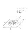
図1は本発明の実施の形態1における細胞電気生理センサ11の細胞保持基板12を示す斜視図であり、この細胞保持基板12内部の実線部分は、後述の凹部13と貫通孔14の外観形状を表している。また図2は図1の破線A−B断面における細胞電気生理センサ11の断面図である。(Embodiment 1)
FIG. 1 is a perspective view showing a
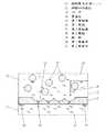
以下に、図2を用いて本発明の細胞電気生理センサ11の構成について説明する。 Below, the structure of the cell
この細胞電気生理センサ11は、細胞保持基板12と、この細胞保持基板12の上方に配置した第1電極槽15と、この第1電極槽15の内部に配置した第1電極16と、細胞保持基板12の下方に配置した第2電極槽17と、この第2電極槽17の内部に配置した第2電極18とを備えている。そしてこの第2電極18は、配線(図示せず)を経て信号検出部(図示せず)に連結されている。 The cell
また、細胞保持基板12の上面には複数の凹部13を形成し、これらの凹部13から細胞保持基板12の下面に向けての最深部から細胞保持基板12の下面に向けて垂直方向に貫通孔14を形成している。 Further, a plurality of
そして隣接する凹部13の内壁は互いに交差させて形成している。また、このような凹部13は、細胞保持基板12の上面の中央に、複数個配置している。そして、これらの凹部13は、いずれも碗型をしている。 The inner walls of
なお、本実施の形態では、図3の細胞保持基板12の上面図のごとく、凹部13は、上面から見ると正六角形状を示すように、1つの凹部13を6つの凹部と均等な距離で隣接させている(細胞保持基板12上において最外周の凹部13は除く)。 In the present embodiment, as shown in the top view of the
なお、図3の点線部分は、隣接する凹部13の内壁を交差させなかった場合の、凹部13の開口部外周の形状を示した。図1、図11、図12においても同様である。 In addition, the dotted line part of FIG. 3 showed the shape of the opening part outer periphery of the
なお、第1電極16は第1電極槽15の内部に注入する電解液(図4の第1電解液20)に、また第2電極18は第2電極槽17の内部に注入する電解液(図4の第2電解液21)にそれぞれ浸漬させ、その電位差を測定できればよいため、第1電極16は、細胞保持基板12の上面に接合させてもよく、第2電極18は貫通孔14の下方に針状の微小電極プローブを配置してもよい。 The
また、本実施の形態において、細胞保持基板12はシリコンで形成した。そして第2電極18は、銅および銀を主成分として形成したが、その他金、白金、パラジウム等を用いてもよい。 In the present embodiment, the
さらに、貫通孔14の開口部の直径は3μmとした。細胞が5〜50μm程度の大きさの場合、細胞と貫通孔14とを高い密着性を持って保持するには、貫通孔14の開口部の直径を3μm以下とすることが望ましいからである。その他、この貫通孔14の開口部の最適な大きさは、測定する細胞の形状、性質によって決定する。 Further, the diameter of the opening of the
次に、本発明の細胞電気生理センサ11の動作について説明する。 Next, the operation of the cell
図4に示すように、まず第1電極槽15に細胞19と第1電解液20を満たし、第2電極槽17には第2電解液21を満たしておく。 As shown in FIG. 4, first, the
そして図5に示すように、細胞保持基板12の下方を減圧するか、上方を加圧することにより、細胞19と第1電解液20を貫通孔14に引き付ける。この時、細胞19は凹部13にトラップされ、貫通孔14の開口部を塞ぐように保持される。以下、前述のように、凹部13に保持された細胞19を被験体細胞19aといい、凹部13に保持されなかった細胞を未保持の細胞19bとする。 Then, as shown in FIG. 5, the
その後、図6に示すように、減圧または加圧により被験体細胞19を凹部13に保持したまま、未保持の細胞(図5の19b)を生理食塩水で洗い流して取り除く。 Thereafter, as shown in FIG. 6, the unretained cells (19 b in FIG. 5) are removed by washing with physiological saline while the
なお、被験体細胞19aが哺乳類筋細胞の場合、第1電解液20としては、例えばK+を155mM、Na+を12mM、Cl-を4.2mM添加した電解液を用い、第2電解液21としては、K+を4mM、Na+を145mM、Cl-を123mM添加した電解液を用いた。なお、第1電解液20と第2電解液21とは、本実施の形態のように異なる組成のものを用いてもよく、同じものを用いてもよい。When the subject cell 19a is a mammalian muscle cell, as the first
次に、細胞保持基板12の下面から吸引するか、あるいはナイスタチンなどの薬剤を投入し、被験体細胞19aに微細小孔を形成する。 Next, suction is performed from the lower surface of the
その後、この被験体細胞19aに化学的刺激、あるいは物理的刺激を付与する。この化学的刺激としては、化学薬品、毒物、物理的刺激としては機械的変異、光、熱、電気、電磁波などが挙げられる。 Thereafter, chemical stimulation or physical stimulation is applied to the subject cell 19a. Examples of chemical stimuli include chemicals, poisons, and physical stimuli include mechanical mutation, light, heat, electricity, and electromagnetic waves.
そして、被験体細胞19aがこれらの刺激に対して活発に反応する場合、被験体細胞19aはその細胞膜にあるイオンチャネルを通じて各種イオンを放出あるいは吸収する。 When the subject cell 19a responds actively to these stimuli, the subject cell 19a releases or absorbs various ions through ion channels in the cell membrane.
そうすると、被験体細胞19aを通るイオン電流が発生し、この被験体細胞19a内外の電位勾配が変化するため、この変化を反応前後の第1電極16と第2電極18との間の電圧、あるいは電流を測定することによって検出する。 Then, an ionic current passing through the subject cell 19a is generated, and the potential gradient inside and outside the subject cell 19a changes. Therefore, this change is caused by the voltage between the
次に、図7〜図9を用いて、本実施の形態における細胞電気生理センサ11の製造方法を説明する。 Next, the manufacturing method of the
まず、図7に示すように、シリコンからなる細胞保持基板12を用意し、細胞保持基板12の上面側にマスク層22を形成する。このとき、マスク層22のエッチングホールの形状および位置は、必要とする貫通孔14の形状および位置とほぼ同じになるように設計しておく。そして、貫通孔14の中心点間距離は、本実施の形態で使用する被験体細胞19aの平均直径の1.5倍になるように統一した。なお、この被験体細胞19aの平均直径は、被験体細胞19aを生理食塩水に含浸させ、この被験体細胞19a内外の浸透圧が平衡となった状態での測定値を基準にするものとする。また、複数の貫通孔14の中心点間距離は、被験体細胞19aの平均直径の1.5倍に限定するものではないが、後述の通り、2倍より短く、かつ上記平均直径より長くなるように設けることが好ましい。 First, as shown in FIG. 7, a
次に、図8のように、ドライエッチング法により、細胞保持基板12に凹部13を形成する。この時、隣接する凹部13同士がそれぞれの内壁を互いに交差させるように、すなわち、隣接する凹部13同士がそれぞれ一部で連結するように形成した。 Next, as shown in FIG. 8, the
また、細胞保持基板12がシリコンである場合、エッチングを促進するエッチングガスとしてSF6、またはCF4、またはNF3、またはXeF2、またはこれらの混合ガスのいずれかを用いることができる。これらはシリコンのエッチングを深さ方向だけでなく、水平方向へのエッチングも促進する作用があるため、細胞保持基板12を半球形状の碗型にエッチングすることができる。When the
また、本実施の形態においては、エッチングを促進するSF6、CF4、NF3、XeF2またはこれらの混合ガスのいずれかのエッチングガスに、N2、Ar、He、H2などのキャリアガスを混合して用いた。In this embodiment, carrier gas such as N2 , Ar, He, H2 is used as an etching gas of SF6 , CF4 , NF3 , XeF2 or a mixed gas thereof that promotes etching. Were used as a mixture.
また、図8からも判るように、本実施の形態における細胞電気生理センサ11の構成では、隣接する凹部13の内壁が互いに交差する部分は、細胞保持基板12の上面より下方にあることから、マスク層22の中央部分の下方は空洞となっており、細胞保持基板12で支えられていない。 Further, as can be seen from FIG. 8, in the configuration of the
よって、マスク層22にはある程度の硬さを有し、外形を維持できる材料が好ましい。特に、エッチング進行中もエッチングホールの形状が不変である材料を用いる必要がある。 Therefore, a material having a certain degree of hardness and capable of maintaining the outer shape is preferable for the
したがって、マスク層22の材料としてはシリコン酸化物、シリコン窒化物、シリコンオキシ窒化物またはこれらの混合物を用いることが望ましい。これらで形成したマスク層22は、エッチング加工時に撓まない程度の硬さを有し、さらにエッチング進行中のエッチングホール形状が不変であるとともに、シリコンを酸化処理、または窒化処理することにより容易に形成することができるためである。 Therefore, it is desirable to use silicon oxide, silicon nitride, silicon oxynitride or a mixture thereof as the material of the
そしてその後、図9で示すように前述のマスク層22を配置した状態で、凹部13の最深部から細胞保持基板12の下面までを垂直方向に貫く貫通孔14を形成する。 Then, as shown in FIG. 9, in the state where the above-described
この貫通孔14を形成する際には前述のエッチングを促進するエッチングガス(SF6、CF4、NF3、XeF2の少なくともいずれか一つ)とエッチングを抑制するガスを交互に用いたドライエッチング加工を行う。このエッチングを抑制するガスとしてはCHF3、C4F8などがある。このエッチングを抑制するガスを、エッチングされた壁面に吹き付けると、その表面にCF2のポリマーである保護膜を形成するため、貫通孔14をマスク層22の下方へ垂直に進行させることができるのである。When forming the through-
この仕組みについて、以下に詳述する。なお、これはエッチングガスとしてSF6、エッチングを抑制するガスとしてC4F8を用いたドライエッチング加工の実験結果に基づき考察したものである。This mechanism will be described in detail below. This is based on the results of dry etching processing using SF6 as an etching gas and C4 F8 as a gas for suppressing etching.
まず、エッチングガスSF6によるドライエッチングの際、細胞保持基板12の上方では、外部コイルの誘導結合法によりプラズマを生成させている。したがって、このプラズマ中には、エッチングガスSF6に含まれるプラスイオン(SF5+)が存在している。First, during dry etching using the etching gas SF6 , plasma is generated above the
次に細胞保持基板12に高周波を印加すると、細胞保持基板12には、マイナスのバイアス電圧が発生し、前述のプラスイオン(SF5+)は細胞保持基板12に向かって垂直に衝突する。Next, when a high frequency is applied to the
その結果、ドライエッチングは細胞保持基板12の垂直方向(下方)に進むことになる。 As a result, dry etching proceeds in the vertical direction (downward) of the
一方、エッチングを抑制するガスC4F8を用いる際には、細胞保持基板12に高周波を加えないでおく。そうすることによって、細胞保持基板12にはバイアス電圧は全く発生しない。On the other hand, when the gas C4 F8 that suppresses etching is used, no high frequency is applied to the
したがって、エッチングを抑制するガスC4F8に含まれるCF+は、偏向を受けることなく、細胞保持基板12のドライエッチング穴の壁面に付着し、均一な膜を形成する。Therefore, CF+ contained in the gas C4 F8 that suppresses etching adheres to the wall surface of the dry etching hole of the
そしてこのCF+の膜は、保護膜となってエッチングを抑制する。そしてこの工程を繰り返すことによって、エッチングは垂直下方のみに進行する。This CF+ film serves as a protective film to suppress etching. By repeating this process, etching proceeds only vertically downward.
以上のように貫通孔14を形成した後、マスク層22を除去すれば、凹部13および貫通孔14を有する細胞保持基板12が完成する。なお、本実施の形態においては、貫通孔14は凹部13の最深部から細胞保持基板12の下面に向けて垂直に形成したが、この細胞保持基板12を斜めに傾けた状態で前述のようなエッチング加工をすることにより、貫通孔14の方向に傾斜をつけることができる。 If the
そして上記のように貫通孔14を形成した後、この細胞保持基板12の下面に真空蒸着法またはスパッタ法を用いて、第2電極18を形成した。 And after forming the through-
本実施の形態における効果を以下に説明する。 The effect in this Embodiment is demonstrated below.
本実施の形態では、図2において、凹部13への細胞19のトラップ率を向上させ、少量の細胞19で検査処理をすることができる。 In the present embodiment, the trap rate of the
それは、隣接する凹部13の内壁は互いに交差しており、この交差部分は曲面で形成された突起形状をしているためである。そしてこの部分に細胞19が着地しても、付着することなく、重力によりいずれかの凹部13に傾き、その内壁に沿って凹部内部へと速やかに転がりトラップされるのである。 This is because the inner walls of the
特に、平滑な平面で付着性の強い細胞を被験体として用いる場合、従来の構成では、その平面に細胞19が付着してしまい、凹部13にトラップされ難いという問題があった。しかし本実施の形態では、隣接する凹部13の開口部間には平面が介在しておらず、突起形状の曲面で形成されていることから、上記のように細胞19が隣接する凹部13の開口部間に付着してしまうのを有効に防ぐことができるのである。 In particular, when a cell having a smooth surface and strong adhesion is used as a subject, the conventional configuration has a problem that the
そしてその結果、凹部13への細胞19のトラップ率を向上させ、少量の細胞で検査処理ができるのである。 As a result, the trap rate of the
さらに、本実施の形態では、細胞電気生理センサ11の信頼性を向上させることができる。その理由を以下に説明する。 Furthermore, in the present embodiment, the reliability of the
すなわち、従来の構成では、凹部13開口部の周辺の平面に付着した未保持の細胞19bが、凹部13に保持された被験体細胞19aと接触してしまい、寄生容量成分を発生させたり、被験体細胞19aのイオンチャネルを封鎖したりしてしまうことがあった。また、未保持の細胞19bが被験体細胞19aと接近、あるいは接触していると、印加した物理化学的刺激の被験体細胞19aへの伝達を阻害することがあった。 That is, in the conventional configuration, the unretained cells 19b attached to the plane around the opening of the
特に細胞保持基板12の表面は一般的に鏡面加工が施されていることが多く、付着性の高い細胞は、その平滑な平面で平たく広がるように付着してしまい、除去するのが非常に困難なことから、上記問題は顕著であった。 In particular, the surface of the
一方、本実施の形態では、隣接する凹部13の開口部間には未保持の細胞19bが付着できるような平面が介在していないため、被験体細胞19aに接触する未保持の細胞19bを著しく低減することができる。また、流水で洗浄することによって、未保持の細胞19bを容易に除去することができる。 On the other hand, in the present embodiment, since there is no plane between the openings of the
よって、寄生容量成分の発生やイオンチャネルの封鎖を抑制し、また印加した物理化学的刺激の伝達の阻害を防ぎ、検出した電気信号の誤差を低減することができる。そしてその結果、細胞電気生理センサ11の信頼性を向上させることができるのである。 Therefore, generation of parasitic capacitance components and blockage of ion channels can be suppressed, inhibition of transmission of applied physicochemical stimulation can be prevented, and errors in detected electrical signals can be reduced. As a result, the reliability of the
また、本実施の形態では、隣接する貫通孔14の中心点間距離を、被験体細胞19aの平均直径の1.5倍とすることにより、一つの凹部13に対し、一つの被験体細胞19aを適切にトラップすることができる。 In the present embodiment, the distance between the center points of the adjacent through-
すなわち、例えば隣接する貫通孔14の中心点間距離を、被験体細胞19aの平均直径の2倍以上とした場合、一つの凹部13の中に複数の細胞19がトラップされてしまい、細胞19同士が押し合って被験体細胞19aが貫通孔14に的確に密着せず、測定誤差が大きくなる場合があった。また、隣接する貫通孔14の中心点間距離を、被験体細胞19aの平均直径以下とした場合、凹部13に細胞19が入るスペースがなくなってしまい、測定が不可能であった。 That is, for example, when the distance between the center points of the adjacent through
一方、本実施の形態1では、一つの凹部13に一つの被験体細胞19aが収容され、貫通孔14と的確に接触し、細胞電気生理センサ11の信頼性を向上させることができる。 On the other hand, in the first embodiment, one subject cell 19a is accommodated in one
さらに、本実施の形態では、図10に示すように、隣接する凹部13の内壁が互いに交差する部分には、上方に突出する丸みを帯びた湾曲部23が形成されている。この湾曲部23は、本実施の形態においては、細胞保持基板12上面から、貫通孔14に対向する部分を中心に、放射状にエッチング加工することによって、隣接する凹部13の内壁の交差する部分が重複してエッチング加工された結果生じたものである。 Further, in the present embodiment, as shown in FIG. 10, a rounded
そして、この湾曲部23の上部は、丸みを帯びた曲面で形成されているため、未保持の細胞19bがこの湾曲部23に着地した場合も、重力に従いいずれかの凹部に速やかに転がってトラップされる。よって、細胞の凹部13へのトラップ率をより向上させることができる。 And since the upper part of this
また、丸みを帯びた湾曲部23では、この部分に着地した細胞19を損傷させたり、この突起部分が欠落したりするのを抑制することができ、細胞電気生理センサ11の信頼性向上に寄与する。 In addition, the rounded
なお、このような湾曲部23は、本実施の形態のように、凹部13のエッチング加工により必然的に形成される場合もあるが、任意に設けてもよい。 In addition, although such a
また、本実施の形態では、図10からも判るように、隣接する複数の凹部13の内壁を互いに交差することによって、この交差している部分より上方に細胞保持基板12の上面を配置している。そしてこれにより、細胞電気生理センサ11の信頼性を向上させることができる。 In this embodiment, as can be seen from FIG. 10, the upper surfaces of the
すなわち、この細胞保持基板12の上面は平滑な平面であるから、未保持の細胞19bが付着しやすいが、上記構成により凹部13に保持された被験体細胞19aとの距離が広がり、接触を回避することができるからである。 That is, since the upper surface of the
また、未保持の細胞19bが細胞保持基板12の上面に積層した場合も、その下方の凹部13との距離が広がっていることから、この凹部13の開口部は過剰に狭小となることは無く、細胞19はこの積層した未保持の細胞19bに阻害されずに凹部13にトラップされることができる。 Further, even when unretained cells 19b are stacked on the upper surface of the
また、本実施の形態では、複数の凹部13が互いの内壁が交差するように連続的に配置したため、細胞保持基板12における凹部13の密度を大きくすることができる。したがって、一つの細胞保持基板12で処理できる試験数を増大することができる。 Moreover, in this Embodiment, since the several recessed
さらに、本実施の形態では、凹部13の形状を碗型とすることにより、球体の被験体細胞19aの形状が大きく変形することが無く、被験体細胞19aを安定に保持することができる。さらに、貫通孔14の開口部が凹部13の最深部となるため、この凹部13の最深部で被験体細胞19aは安定して存在し、この被験体細胞19aと貫通孔14との密着性が向上する。その結果、測定誤差を低減し、細胞電気生理センサ11の信頼性を向上させることができる。 Furthermore, in this Embodiment, the shape of the recessed
なお、細胞保持基板12としてシリコンを用いたが、シリコンの中に酸化シリコン層が埋め込まれた基板を用いることもできる。このような基板はSOI基板と呼ばれ、これにより、貫通孔14をドライエッチングによって形成する際、酸化シリコン層がエッチングストップ層となるのでより簡単な製造方法とすることができる。 Although silicon is used as the
また、本実施の形態では、隣接する凹部13間に介在する平面を無くすように凹部13を配置したが、本発明は、上記のように平面を完全に除去する構造に限定するものではない。 Further, in the present embodiment, the
(実施の形態2)
本実施の形態2と実施の形態1との違いは、図11の細胞保持基板12の上面図から判るように、一つの凹部13の内壁を、隣接する4つの凹部13の内壁とそれぞれ交差させ、凹部13の開口部の形状を、上面から見ると正方形状を示すように形成したことである(最外周の凹部13を除く)。(Embodiment 2)
As can be seen from the top view of the
本実施の形態2は実施の形態1よりも、隣接する複数の凹部13の内壁が交差する部分が大きくなるため、細胞保持基板12における凹部13の密度がより増大し、一度に処理できる試験数を更に増やすことができる。 In the second embodiment, since the portion where the inner walls of the plurality of adjacent
その他の構成、動作、製造方法および効果等は実施の形態1と同様であるため省略する。 Other configurations, operations, manufacturing methods, effects, and the like are the same as those in the first embodiment, and are omitted.
(実施の形態3)
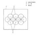
本実施の形態3と実施の形態1との違いは、図12の細胞保持基板12の上面図で示すように、細胞保持基板12の上面の全面に凹部13を形成したことである。(Embodiment 3)
The difference between the third embodiment and the first embodiment is that the
このような構成とすることによって、細胞19の凹部13へのトラップ率を著しく向上させることができる。 By setting it as such a structure, the trap rate to the recessed
また細胞保持基板12の上面から平面がほぼ完全に排除されることから、未保持の細胞19bと被験体細胞19aとの接触を著しく低減することができる。したがって、寄生容量成分の発生やイオンチャネルの封鎖、および印加した物理化学的信号の伝達の阻害による測定誤差を低減し、細胞電気生理センサ11の信頼性を向上させることができる。 Further, since the plane is almost completely removed from the upper surface of the
なお、本実施の形態3では、複数の凹部13のうち、最外周の凹部13は形状が不完全であるから、この凹部13にトラップされた被験体細胞19aは測定の対象から除外している。また、細胞保持基板12や第2電極槽17の形状により、貫通孔14が形成しにくい凹部13には貫通孔14を形成せず、測定の対象から除外している。 In the third embodiment, among the plurality of
その他の構成、動作方法、製造方法および効果については実施の形態1と同様であるため省略する。 Since other configurations, operation methods, manufacturing methods, and effects are the same as those in the first embodiment, the description thereof is omitted.
本発明の細胞電気生理センサおよびその製造方法は、細胞の凹部へのトラップ率を向上させることができる。 The cell electrophysiological sensor and the method for producing the same of the present invention can improve the trap rate of the cells into the recesses.
よって、少量の細胞で迅速な処理が可能となり、医療分野等における細胞電気生理センサとして、大いに利用可能性を有するものである。 Therefore, rapid processing is possible with a small amount of cells, and it has great applicability as a cell electrophysiological sensor in the medical field and the like.
11 細胞電気生理センサ
12 細胞保持基板
13 凹部
14 貫通孔
15 第1電極槽
16 第1電極
17 第2電極槽
18 第2電極
19 細胞
19a 被験体細胞
19b 未保持の細胞
20 第1電解液
21 第2電解液
22 マスク層
23 湾曲部DESCRIPTION OF
Claims (12)
Translated fromJapanesePriority Applications (1)
| Application Number | Priority Date | Filing Date | Title |
|---|---|---|---|
| JP2006046548AJP4844161B2 (en) | 2006-02-23 | 2006-02-23 | Cell electrophysiological sensor, measuring method using the same, and manufacturing method thereof |
Applications Claiming Priority (1)
| Application Number | Priority Date | Filing Date | Title |
|---|---|---|---|
| JP2006046548AJP4844161B2 (en) | 2006-02-23 | 2006-02-23 | Cell electrophysiological sensor, measuring method using the same, and manufacturing method thereof |
Publications (2)
| Publication Number | Publication Date |
|---|---|
| JP2007225425A JP2007225425A (en) | 2007-09-06 |
| JP4844161B2true JP4844161B2 (en) | 2011-12-28 |
Family
ID=38547383
Family Applications (1)
| Application Number | Title | Priority Date | Filing Date |
|---|---|---|---|
| JP2006046548AExpired - Fee RelatedJP4844161B2 (en) | 2006-02-23 | 2006-02-23 | Cell electrophysiological sensor, measuring method using the same, and manufacturing method thereof |
Country Status (1)
| Country | Link |
|---|---|
| JP (1) | JP4844161B2 (en) |
Families Citing this family (6)
| Publication number | Priority date | Publication date | Assignee | Title |
|---|---|---|---|---|
| KR101099670B1 (en)* | 2009-04-14 | 2011-12-29 | 한국과학기술원 | Single cell assay device |
| EP2554654A4 (en)* | 2010-03-30 | 2014-07-09 | Panasonic Corp | DETECTION DEVICE |
| WO2012120852A1 (en)* | 2011-03-04 | 2012-09-13 | パナソニック株式会社 | Sensor chip |
| US10138452B2 (en) | 2014-08-05 | 2018-11-27 | Yamaha Hatsudoki Kabushiki Kaisha | Object-holding device |
| JP6270918B2 (en)* | 2016-06-14 | 2018-01-31 | ヤマハ発動機株式会社 | Container structure |
| JP6218199B1 (en)* | 2016-10-06 | 2017-10-25 | 日本航空電子工業株式会社 | Electrochemical measuring device and transducer |
Family Cites Families (6)
| Publication number | Priority date | Publication date | Assignee | Title |
|---|---|---|---|---|
| JP2662215B2 (en)* | 1986-11-19 | 1997-10-08 | 株式会社日立製作所 | Cell holding device |
| JPH1183798A (en)* | 1997-09-02 | 1999-03-26 | Shimadzu Corp | Electrophoresis member and electrophoresis apparatus using the same |
| EP2332651A3 (en)* | 2001-10-25 | 2011-08-31 | Bar Ilan University | Interactive transparent individual cells biochip processor |
| JP2004333404A (en)* | 2003-05-12 | 2004-11-25 | Hitachi Ltd | Microreactor, method for manufacturing the same, and sample screening apparatus |
| US7547381B2 (en)* | 2003-09-26 | 2009-06-16 | Agency For Science, Technology And Research And National University Of Singapore | Sensor array integrated electrochemical chip, method of forming same, and electrode coating |
| WO2005116242A1 (en)* | 2004-05-31 | 2005-12-08 | Matsushita Electric Industrial Co., Ltd. | Medicine safety testing method and medicine safety testing system |
- 2006
- 2006-02-23JPJP2006046548Apatent/JP4844161B2/ennot_activeExpired - Fee Related
Also Published As
| Publication number | Publication date |
|---|---|
| JP2007225425A (en) | 2007-09-06 |
Similar Documents
| Publication | Publication Date | Title |
|---|---|---|
| US8354271B2 (en) | Biosensor | |
| JP4844161B2 (en) | Cell electrophysiological sensor, measuring method using the same, and manufacturing method thereof | |
| JP4784696B2 (en) | Cell potential measuring device, substrate used therefor, and method for manufacturing substrate for cell potential measuring device | |
| JP5458887B2 (en) | Silicon structure and sensor chip | |
| WO2003104788A1 (en) | Extracellular potential measuring device and method for fabricating the same | |
| JP4449519B2 (en) | Extracellular potential measuring device and manufacturing method thereof | |
| JP4596009B2 (en) | Cell electrophysiological sensor chip, cell electrophysiological sensor using the chip, and method for manufacturing cell electrophysiological sensor chip | |
| JP2004271331A (en) | Extracellular potential measurement device and method of manufacturing the same | |
| US8257962B2 (en) | Extracellular potential measuring device and its manufacturing method | |
| JP3945317B2 (en) | Extracellular potential measuring device and manufacturing method thereof | |
| JP4868067B2 (en) | Cell electrophysiological sensor chip, cell electrophysiological sensor using the same, and method for manufacturing cell electrophysiological sensor chip | |
| JP3925439B2 (en) | Extracellular potential measuring device and manufacturing method thereof | |
| US10962525B2 (en) | Process for characterizing a blood sample | |
| JP2009291135A (en) | Cellular electrophysiological sensor | |
| JP4742973B2 (en) | Cell electrophysiology measuring device and method of manufacturing the same | |
| US8202439B2 (en) | Diaphragm and device for measuring cellular potential using the same, manufacturing method of the diaphragm | |
| JP4747852B2 (en) | Cell electrophysiological sensor and manufacturing method thereof | |
| JP5011984B2 (en) | Cell electrophysiological sensor | |
| WO2012120852A1 (en) | Sensor chip | |
| JP4830545B2 (en) | Method for manufacturing cell electrophysiological sensor | |
| JP2009002876A (en) | Cell electrophysiological sensor | |
| KR20170116458A (en) | Wearable biodevice and manufacturing method thereof | |
| JP2013124861A (en) | Sensor chip |
Legal Events
| Date | Code | Title | Description |
|---|---|---|---|
| A621 | Written request for application examination | Free format text:JAPANESE INTERMEDIATE CODE: A621 Effective date:20081226 | |
| RD01 | Notification of change of attorney | Free format text:JAPANESE INTERMEDIATE CODE: A7421 Effective date:20091127 | |
| A977 | Report on retrieval | Free format text:JAPANESE INTERMEDIATE CODE: A971007 Effective date:20110127 | |
| A131 | Notification of reasons for refusal | Free format text:JAPANESE INTERMEDIATE CODE: A131 Effective date:20110201 | |
| A521 | Request for written amendment filed | Free format text:JAPANESE INTERMEDIATE CODE: A523 Effective date:20110330 | |
| TRDD | Decision of grant or rejection written | ||
| A01 | Written decision to grant a patent or to grant a registration (utility model) | Free format text:JAPANESE INTERMEDIATE CODE: A01 Effective date:20110913 | |
| A01 | Written decision to grant a patent or to grant a registration (utility model) | Free format text:JAPANESE INTERMEDIATE CODE: A01 | |
| A61 | First payment of annual fees (during grant procedure) | Free format text:JAPANESE INTERMEDIATE CODE: A61 Effective date:20110926 | |
| FPAY | Renewal fee payment (event date is renewal date of database) | Free format text:PAYMENT UNTIL: 20141021 Year of fee payment:3 | |
| R151 | Written notification of patent or utility model registration | Ref document number:4844161 Country of ref document:JP Free format text:JAPANESE INTERMEDIATE CODE: R151 | |
| FPAY | Renewal fee payment (event date is renewal date of database) | Free format text:PAYMENT UNTIL: 20141021 Year of fee payment:3 | |
| LAPS | Cancellation because of no payment of annual fees |