Movatterモバイル変換


[0]ホーム

URL:


JP4843254B2 - Router - Google Patents

Router
Download PDF

Info

Publication number
JP4843254B2
JP4843254B2JP2005151350AJP2005151350AJP4843254B2JP 4843254 B2JP4843254 B2JP 4843254B2JP 2005151350 AJP2005151350 AJP 2005151350AJP 2005151350 AJP2005151350 AJP 2005151350AJP 4843254 B2JP4843254 B2JP 4843254B2
Authority
JP
Japan
Prior art keywords
main body
base
engagement
router
work material
Prior art date
Legal status (The legal status is an assumption and is not a legal conclusion. Google has not performed a legal analysis and makes no representation as to the accuracy of the status listed.)
Expired - Fee Related
Application number
JP2005151350A
Other languages
Japanese (ja)
Other versions
JP2006326931A5 (en
JP2006326931A (en
Inventor
章 小野瀬
洋樹 内田
Current Assignee (The listed assignees may be inaccurate. Google has not performed a legal analysis and makes no representation or warranty as to the accuracy of the list.)
Koki Holdings Co Ltd
Original Assignee
Hitachi Koki Co Ltd
Priority date (The priority date is an assumption and is not a legal conclusion. Google has not performed a legal analysis and makes no representation as to the accuracy of the date listed.)
Filing date
Publication date
Application filed by Hitachi Koki Co LtdfiledCriticalHitachi Koki Co Ltd
Priority to JP2005151350ApriorityCriticalpatent/JP4843254B2/en
Priority to US11/438,369prioritypatent/US7367760B2/en
Priority to DE602006004249Tprioritypatent/DE602006004249D1/en
Priority to AT06252691Tprioritypatent/ATE417713T1/en
Priority to CN200610142276.9Aprioritypatent/CN1911594B/en
Priority to EP06252691Aprioritypatent/EP1726415B1/en
Publication of JP2006326931ApublicationCriticalpatent/JP2006326931A/en
Priority to US12/115,165prioritypatent/US7726918B2/en
Publication of JP2006326931A5publicationCriticalpatent/JP2006326931A5/ja
Application grantedgrantedCritical
Publication of JP4843254B2publicationCriticalpatent/JP4843254B2/en
Anticipated expirationlegal-statusCritical
Expired - Fee Relatedlegal-statusCriticalCurrent

Links

Images

Classifications

Landscapes

Abstract

A power tool has a base (110), a main unit (130), a cutter (151), a bolt (117), an engagement member (138), and a unit. The base has a sliding surface (110A) slidable on a workpiece, another surface opposite to the sliding surface, and an opening in the base. The main unit is movable in a first direction substantially perpendicular to the sliding surface. The cutter is driven by an electric motor in the main unit to protrude through the opening from the sliding surface during an operation. The bolt (117) extends in the first direction on the first side, a first male thread (117B), and one end supported by the base. The bolt is rotatable about the longitudinal axis. The engagement member (138) has a first female thread (138b) threadably engaged with the male thread. The engagement member is movable between an engaged position with the bolt and a disengaged position therewith. The unit (139,142,143) maintains the engagement member at the disengaged position in a second direction. The rotation of the bolt causes the first male thread portion (117B) to thread with respect to the first female thread portion (138b), thereby moving the main unit in the first direction and adjusting a distance of the main unit to the sliding surface.

Description

Translated fromJapanese

本発明はルータに関し、特にベースに対して本体を移動させることにより刃物の位置を微調整して、被削材に形成される溝の深さを調整するルータに関する。  The present invention relates to a router, and more particularly to a router that adjusts the depth of a groove formed in a work material by finely adjusting the position of a cutter by moving a main body with respect to a base.

被削材に溝等を形成するための電動工具たるルータが従来より知られている。ルータは、ベースと本体と刃物とハンドルとを備えており、ベースは被削材上を摺動する摺動面を有する。摺動面には、当該摺動面を垂直の方向に貫通するベース貫通孔が形成されている。  Conventionally, a router as an electric tool for forming a groove or the like in a work material is known. The router includes a base, a main body, a cutter, and a handle, and the base has a sliding surface that slides on the work material. A base through-hole penetrating the sliding surface in the vertical direction is formed on the sliding surface.

本体は、摺動面の反被削材側、即ち被削材が当接する摺動面の側とは反対の側において摺動面に垂直の方向にベースに対して移動可能に支持されている。通常では、摺動面が当接する被削材の面は水平に配置され、摺動面も水平に配置されるため、本体の移動方向である摺動面に垂直の方向は、鉛直上下方向に略一致する。従って、本体は、通常では、ベースに対して上下動可能に支持されている。また本体には、後述の一対の円柱部材を挿入するための一対の貫通孔が形成されている。  The main body is supported so as to be movable with respect to the base in a direction perpendicular to the sliding surface on the side opposite to the sliding surface on which the work material comes into contact, that is, on the side opposite to the sliding surface with which the work material comes into contact. . Normally, the surface of the work material with which the sliding surface abuts is arranged horizontally, and the sliding surface is also arranged horizontally, so the direction perpendicular to the sliding surface, which is the moving direction of the main body, is the vertical vertical direction. It almost agrees. Therefore, the main body is normally supported so as to be movable up and down with respect to the base. The main body is formed with a pair of through holes for inserting a pair of cylindrical members described later.

ベースに対する本体の支持は一対のコラムと呼ばれる円柱部材を介して行われる。一対の円柱部材は、摺動面に垂直の方向に指向し互いに平行に配置される。一対の円柱部材の一端はベースに対して移動不能に固定され、他端側は、本体に形成された一対の貫通孔に挿入されている。一対の貫通孔が形成されている本体の部分の一方には、本体に対して一対の円柱部材を一時的に移動不能に固定するための固定部材が設けられている。本体に対して一対の円柱部材を一時的に移動不能に固定することにより、ベースに対して本体を一時的に移動不能に固定することができる。  The main body is supported with respect to the base via a pair of columnar members called columns. The pair of cylindrical members are oriented in a direction perpendicular to the sliding surface and arranged in parallel to each other. One end of the pair of columnar members is fixed so as not to move with respect to the base, and the other end is inserted into a pair of through holes formed in the main body. One of the portions of the main body in which the pair of through holes is formed is provided with a fixing member for temporarily fixing the pair of columnar members to the main body so as not to move. By temporarily fixing the pair of columnar members to the main body so as not to move, the main body can be temporarily fixed to the base so as not to move.

また、本体は、被削材にベースの摺動面が当接し摺動面が水平とされた状態の本体の左右方向外方へ突出する本体突出部を有する。ハンドルは本体突出部の突出端にそれぞれ1つずつ設けられており、右手、左手でそれぞれ把持することができるように構成されている。  The main body has a main body protruding portion that protrudes outward in the left-right direction of the main body in a state where the sliding surface of the base is in contact with the work material and the sliding surface is horizontal. One handle is provided at each projecting end of the main body projecting portion, and is configured to be gripped by the right hand and the left hand.

また、本体内には電動機が内蔵されている。電動機には、摺動面に垂直の方向であって略ベースへ向かう方向へ延出する出力軸が設けられている。刃物は出力軸の端部に装着されている。本体が上下動することによりベース貫通孔内において、ベースの摺動面よりも被削材側、即ち、摺動面の被削材に当接している側へ突出可能である。  An electric motor is built in the main body. The electric motor is provided with an output shaft that extends in a direction perpendicular to the sliding surface and substantially toward the base. The blade is attached to the end of the output shaft. As the main body moves up and down, it can protrude from the sliding surface of the base to the work material side, that is, the side of the sliding surface that is in contact with the work material, in the base through hole.

ルータを用いて被削材に溝を形成する方法の一例を挙げると次のとおりである。固定部材による一対の円柱状部材の本体への固定を解除しベースに対して本体を移動可能の状態とし、作業者は、ルータのハンドルを右手、左手でそれぞれ把持することにより本体を支持しながら、ベースに対する所望の位置へ本体を移動させる。そして、固定部材によって一対の円柱状部材を本体へ固定して本体をベースに対して移動不能の状態とする。このことによりベース貫通孔内において、ベースの摺動面よりも被削材側へ刃物を所望の量だけ突出させる。この所望の量が被削材に形成される溝の深さとなる。  An example of a method for forming a groove in a work material using a router is as follows. The pair of columnar members fixed to the main body by the fixing member is released and the main body can be moved with respect to the base, and the operator supports the main body by holding the router handle with the right hand and the left hand respectively. , Move the body to the desired position relative to the base. Then, the pair of columnar members are fixed to the main body by the fixing member so that the main body cannot move relative to the base. As a result, a desired amount of the blade is projected from the sliding surface of the base to the work material side in the base through hole. This desired amount is the depth of the groove formed in the work material.

この状態で、ルータのハンドルを右手、左手でそれぞれ把持することによりルータ支持しながら、略水平とされた被削材上でベースの摺動面に当接する被削材の面に沿ってルータを移動させる。このことにより、ベースの摺動面よりも被削材側へ突出する刃物によって被削材に溝が形成される。このようなルータは、例えば特公平6−020726号公報(特許文献1)に記載されている。
特公平6−020726号公報
In this state, while holding the router handle with the right and left hands to support the router, hold the router along the surface of the work material that comes into contact with the sliding surface of the base on the work material that is approximately level. Move. As a result, a groove is formed in the work material by the blade that protrudes toward the work material from the sliding surface of the base. Such a router is described in, for example, Japanese Patent Publication No. 6-020726 (Patent Document 1).
Japanese Patent Publication No. 6-020726

しかし従来のルータでは、上述のように作業者は、ルータのハンドルを右手、左手でそれぞれ把持することにより本体を支持しながら、ベースに対する所望の本体の位置へ本体を移動させて、ベースの摺動面よりも被削材側へ刃物を所望の量だけ突出させていたため、刃物の突出量を微調整することは困難であった。  However, in the conventional router, as described above, the operator moves the main body to the desired position of the main body with respect to the base while supporting the main body by holding the router handle with the right hand and the left hand, respectively. Since the cutter is protruded by a desired amount to the work material side from the moving surface, it is difficult to finely adjust the protrusion amount of the cutter.

また、他のルータの使用方法としては、いわゆるルータテーブルの端縁部にルータを支持するための支持部材をルータに取付け、ルータのベースを本体に対して鉛直上方に位置させた状態で、当該支持部材によりルータテーブルの端縁部においてルータを支持した状態で使用する方法がある。この場合にはハンドルを右手、左手でそれぞれ把持することにより比較的重い本体を重力に抗して支持して鉛直上下方向に移動させて刃物の突出量を調整するため、刃物の突出量の微調整は更に困難であった。  In addition, as another method of using the router, a support member for supporting the router is attached to the edge of the so-called router table, and the router base is positioned vertically above the main body. There is a method in which the router is used in a state where the router is supported at the edge of the router table by the support member. In this case, holding the handle with the right hand and left hand respectively, the relatively heavy body is supported against gravity and moved vertically up and down to adjust the amount of protrusion of the blade. Adjustment was even more difficult.

また、例えば、ベースに対する本体の移動量を微調整可能とする微調整機構を設けることが考えられるが、微調整を行う前の段階では、本体を所望の位置の近傍へ移動させることは従来と同様に必要であるため、ハンドルを右手、左手でそれぞれ把持することにより本体を支持して移動させることもできなければならない。このため、微調整機構による微調整が可能な微調整モードと、微調整機構による微調整を行うことができずハンドルを把持して本体を支持しながら移動させる本体移動モードとの切替えが可能でなければならない。更に、これらのモードを、作業者が手で支持等することなく維持することができなければ、ハンドルを把持することにより本体を支持して移動させることや、微調整することを容易に行うことは困難である。  In addition, for example, it is conceivable to provide a fine adjustment mechanism that enables fine adjustment of the amount of movement of the main body with respect to the base. Similarly, since it is necessary, it must be possible to support and move the main body by holding the handle with the right hand and the left hand. For this reason, it is possible to switch between a fine adjustment mode in which fine adjustment by the fine adjustment mechanism is possible, and a main body movement mode in which the fine adjustment by the fine adjustment mechanism cannot be performed and the handle is held and moved while supporting the main body. There must be. Furthermore, if these modes cannot be maintained without manual support by the operator, the main body can be supported and moved by gripping the handle, and fine adjustment can be easily performed. It is difficult.

そこで、本発明は、ベースに対する本体の移動量を容易に微調整可能とすることにより刃物の突出量を微調整可能として、且つ、当該微調整を行う微調整のモードを維持することが可能なルータを提供することを目的とする。  Therefore, the present invention makes it possible to easily adjust the amount of movement of the main body with respect to the base, thereby making it possible to finely adjust the protrusion amount of the blade, and to maintain a fine adjustment mode for performing the fine adjustment. The purpose is to provide a router.

上記目的を達成するために、本発明は、開口部と被削材上を摺動する摺動面とを有するベースと、該摺動面の反被削材側において該摺動面の該反被削材側に対向して該ベースに垂直の方向に上下動可能に該ベースに支持され、電動機を内蔵し、該摺動面に略垂直の方向であって該ベースへ向かう方向へ該電動機から延出する出力軸を有する本体と、該出力軸の端部に装着された刃物とを備え、該開口部は該ベースを貫通して該被削材側と該反被削材側とに開口し、該刃物は、該本体の上下動により該反被削材側から該被削材側へと向かう方向において該ベースへ接近させられて該ベースの該摺動面よりも該被削材側に該開口部から突出可能なルータにおいて、該摺動面の該反被削材側において該摺動面に略垂直の方向に延出し、一端が該摺動面に垂直の方向へ移動不能且つ回転可能に該ベースに支承され、少なくとも一部に該反被削材側から該被削材側へと向かう方向において該本体を位置調整するための雄ネジ部を有するボルトと、該ボルトの該雄ネジ部と係合して螺合可能であり該反被削材側から該被削材側へと向かう方向において該本体を位置調整するための雌ネジを有し、該ボルトの該雄ネジ部と該雌ネジとが係合する係合位置と、該雄ネジ部と該雌ネジとの係合が解除される係合解除位置との間で移動可能な係合部材と、該係合部材を該係合解除位置に保持するための係合解除位置保持手段と、該係合部材を該係合位置に保持するための弾性部材と、を有し、該本体には本体雌ネジが螺刻され、該係合解除位置保持手段は該係合部材の移動方向において当接可能な駆動部材を備え、該駆動部材の外周面には該本体雌ネジと螺合する駆動部材雄ネジが設けられ、該駆動部材の雄ネジの螺進退により該係合部材を該係合位置又は該係合解除位置とするルータを提供している。In order to achieve the above object, the present invention provides a base having an opening and a sliding surface that slides on the work material, and the reaction of the sliding surface on the anti-work material side of the sliding surface. Opposite to the work material side, supported by the base so as to be movable up and down in a direction perpendicular to the base, incorporating an electric motor, and moving the electric motor in a direction substantially perpendicular to the sliding surface and toward the base A main body having an output shaft extending from the output shaft, and a cutter attached to an end portion of the output shaft, and the opening penetrates the base to the work material side and the anti-work material side. The cutting tool is opened and moved closer to the base in a direction from the anti-work material side to the work material side by the vertical movement of the main body, and the work material is more than the sliding surface of the base. In the router that can protrude from the opening to the side, the sliding surface extends in a direction substantially perpendicular to the sliding surface on the side opposite to the work material, and one end of the sliding surface A male threaded portion that is supported by the base so that it cannot move in a direction perpendicular to the base and is rotatable, and at least partially adjusts the position of the main body in the direction from the anti-work material side to the work material side And a female screw for adjusting the position of the main body in the direction from the opposite work material side to the work material side. And can be moved between an engagement position where the male screw portion and the female screw of the bolt are engaged, and an engagement release position where the engagement of the male screw portion and the female screw is released. An engagement member, an engagement release position holding means for holding the engagement member in the engagement release position, and an elastic member for holding the engagement member in the engagement position, The main body is threaded with a main body female screw, and the disengaging position holding means can be abutted in the moving direction of the engaging member. A drive member male screw threadably engaged with the main body female screw is provided on the outer peripheral surface of the drive member, and the engagement member is moved to the engagement position or the engagement by the forward and backward movement of the male screw of the drive member. A router is provided as arelease position .

また、該駆動部材雄ネジと該本体雌ネジとの螺合による該駆動部材の螺進退方向は該ボルトの軸心に垂直の方向に一致し、該係合部材は該駆動部材の螺進退に連動して該係合位置又は該係合解除位置となることが好ましい。Further, the screwing / retracting direction of the driving member by the screwing of the driving member male screw and the mainbody female screw coincides with the direction perpendicular to the axial center of the bolt, and the engaging member corresponds to the screwing / retreating of the driving member. It is preferable that the engagement position or the disengagement position is interlocked.

また、該係合部材は、該係合部材の移動方向へ該係合部材の外周面から延出する係合部材延出部を有し、該係合部材延出部の延出端にはフランジ状の当接部材が設けられ、該駆動部材は、該係合部材延出部の周面上であって該当接部材と該係合部材の外周面との間に配置され、該係合部材延出部の軸を中心として回動可能、且つ該当接部材と該係合部材の外周面とに当接可能であることが好ましい。  The engaging member has an engaging member extending portion extending from the outer peripheral surface of the engaging member in the moving direction of the engaging member, and the extending end of the engaging member extending portion is A flange-shaped contact member is provided, and the drive member is disposed on the peripheral surface of the engaging member extending portion and between the contact member and the outer peripheral surface of the engaging member. It is preferable that the member can be rotated about the axis of the member extending portion and can be brought into contact with the contact member and the outer peripheral surface of the engagement member.

また、該駆動部材は、該駆動部材雄ネジと該本体雌ネジとの螺合により該ボルトの軸心に垂直の方向に螺進退可能であり、該駆動部材が該ボルト側へ螺進することにより該駆動部材は該係合部材に対し当接押圧して該係合部材を該係合解除位置へ移動させ、該駆動部材を螺退させるときには、該係合部材は該弾性部材の押圧力により該係合位置へと移動させられることが好ましい。The drive member can be screwed back and forth in a direction perpendicular to the axial center of the bolt by screwing the drive member male screw and the mainbody female screw , and the drive member can be screwed to the bolt side. Thus, when the driving member contacts and presses against the engaging member to move the engaging member to the disengaged position, and the driving member is screwed out, the engaging member is pressed by the elastic member. Is preferably moved to the engagement position.

また、回動操作可能であり、回動操作されることにより該駆動部材が螺進退するように該駆動部材へ回動力を伝達する操作部材と、該操作部材の回動位置を規制する規制手段とを有し、該規制手段は該係合部材が該係合位置または該係合解除位置にあるときに該操作部材の回動を規制することが好ましい。  Further, an operation member that is capable of rotating operation and transmits a rotational force to the drive member so that the drive member is screwed back and forth by the rotation operation, and a restriction unit that restricts the rotation position of the operation member. Preferably, the restricting means restricts the rotation of the operating member when the engaging member is in the engaged position or the disengaged position.

また、該操作部材は、該駆動部材の回動軸に垂直の方向に延びる延出部を有するレバー部材であり、該規制手段は該延出部の回動範囲内の該本体の部分に設けられ、該延出部が回動して該延出部に当接することにより該レバー部材の回動を規制することが好ましい。  The operating member is a lever member having an extending portion extending in a direction perpendicular to the rotation axis of the drive member, and the restricting means is provided in a portion of the main body within the rotation range of the extending portion. In addition, it is preferable that the rotation of the lever member is restricted by the extension portion rotating and contacting the extension portion.

また、該レバー部材と該駆動部材とは互いに連結される連結部を有し該レバー部材と該駆動部材と相対的に回動可能であり、該連結部には、該レバー部材と該駆動部材との相対的な回動を規制し該レバー部材を該駆動部材に対して回動不能に固定する固定部材が設けられていることが好ましい。  Further, the lever member and the drive member have a connecting portion connected to each other, and are rotatable relative to the lever member and the driving member. The connecting member includes the lever member and the driving member. It is preferable to provide a fixing member that restricts relative rotation of the lever member and fixes the lever member to the drive member so as not to rotate.

請求項1記載のルータによれば、該摺動面の反被削材側において該摺動面に略垂直の方向に延出し、一端が該摺動面に垂直の方向へ移動不能且つ回転可能に該ベースに支承され、少なくとも一部に雄ネジ部を有するボルトと、該ボルトの該雄ネジ部とが係合して螺合可能な雌ネジを有し、該ボルトの該雄ネジ部と該雌ネジとが係合する係合位置と、該雄ネジ部と該雌ネジとの係合が解除される係合解除位置との間で移動可能な係合部材と、該係合部材を該係合解除位置に保持するための係合解除位置保持手段とを有するため、係合部材が係合位置にあるときに、ボルトを回転させることによってボルトに対して係合部材が螺進退し、係合部材が本体と一体でボルトの軸方向に移動可能である場合には、係合部材の螺進退により本体を当該螺進退方向へ移動させることができる。このため、ベース及びボルトに対する本体の位置を微調整することができる。また、係合部材を係合位置に保持するための弾性部材を有しているため、駆動部材の螺進退に伴い駆動部材と係合部材とが一体で移動可能な場合には、駆動部材の雄ネジを本体雌ネジに押圧させることができ、雄ネジと本体雌ネジとの間のガタの発生を防止することができる。また、該本体には本体雌ネジが螺刻され、該係合解除位置保持手段は該係合部材の移動方向において当接可能な駆動部材を備え、該駆動部材の外周面には該本体雌ネジと螺合する駆動部材雄ネジが設けられ、該駆動部材の雄ネジの螺進退により該係合部材を該係合位置又は該係合解除位置とするため、雄ネジを螺進退させなければ、係合部材を係合位置、又は係合解除位置に維持させることができる。このため、作業者が係合部材を係合位置、又は係合解除位置に維持させるための煩わしい操作の必要性をなくすことができる。According to the router ofclaim 1, the sliding surface extends in a direction substantially perpendicular to the sliding surface on the side opposite to the work material, and one end is immovable and rotatable in a direction perpendicular to the sliding surface. A bolt having a male threaded portion at least partially supported by the base, and a female screw engageable with the male threaded portion of the bolt, and the male threaded portion of the bolt. An engagement member movable between an engagement position where the female screw engages and an engagement release position where the male screw portion and the female screw are disengaged; and And a disengagement position retaining means for retaining the disengagement position. Therefore, when the engagement member is in the engagement position, the engagement member is screwed back and forth by rotating the bolt. When the engaging member is integral with the main body and is movable in the axial direction of the bolt, the main body is It can be moved in the direction. For this reason, the position of the main body with respect to the base and the bolt can be finely adjusted. In addition, since the elastic member for holding the engaging member in the engaging position is provided, when the driving member and the engaging member can move together as the driving member is screwed back and forth, the driving member The male screw can be pressed against the main female screw, and play between the male screw and the main female screw can be prevented.Also, a main body female screw is threaded on the main body, and the disengagement position holding means includes a drive member capable of contacting in the moving direction of the engagement member, and the main body female is provided on the outer peripheral surface of the drive member. A drive member male screw that engages with the screw is provided, and the engagement member is set to the engagement position or the disengagement position by screwing back and forth of the male screw of the drive member. The engagement member can be maintained in the engagement position or the engagement release position. For this reason, the necessity for the troublesome operation for an operator to maintain an engagement member in an engagement position or an engagement release position can be eliminated.

請求項3記載のルータによれば、該係合部材は、該係合部材の移動方向へ該係合部材の外周面から延出する係合部材延出部を有し、該係合部材延出部の延出端にはフランジ状の当接部材が設けられ、該駆動部材は、該係合部材延出部の周面上であって該当接部材と該係合部材の外周面との間に配置され、該係合部材延出部の軸を中心として回動可能、且つ該当接部材と該係合部材の外周面とに当接可能であるため、係合部材は駆動部材の螺進退に伴い駆動部材と一体で、係合位置から係合解除位置への移動、又は係合解除位置から係合解除位置への移動を行うことができる。According to the router ofclaim 3, the engaging member has an engaging member extending portion that extends from the outer peripheral surface of the engaging member in the moving direction of the engaging member, and the engaging member extends. A flange-shaped abutting member is provided at the extended end of the protruding portion, and the drive member is located on the peripheral surface of the engaging member extending portion and between the corresponding contact member and the outer peripheral surface of the engaging member. The engaging member is arranged between the engaging member extending portion and is rotatable about the axis of the engaging member extending portion, and can contact the contact member and the outer peripheral surface of the engaging member. Along with advancement and retraction, movement from the engagement position to the engagement release position or movement from the engagement release position to the engagement release position can be performed integrally with the drive member.

請求項4記載のルータによれば、該駆動部材は、該駆動部材雄ネジと該本体雌ネジとの螺合により該ボルトの軸心に垂直の方向に螺進退可能であるため、該駆動部材が該ボルト側へ螺進することにより該駆動部材は該係合部材に対し当接押圧して該係合部材を該係合解除位置へ移動させることができる。また、該駆動部材を螺退させるときには、該係合部材を該弾性部材の押圧力により該係合位置へと移動させることができる。According to the router of claim 4, the drive member can be screwed back and forth in a direction perpendicular to the axial center of the bolt by screwing the drive member male screw and the mainbody female screw. When the screw is screwed to the bolt side, the drive member can be pressed against the engagement member to move the engagement member to the disengagement position. Further, when the drive member is screwed, the engagement member can be moved to the engagement position by the pressing force of the elastic member.

請求項5又は請求項6記載のルータによれば、回動操作可能であり、回動操作されることにより該駆動部材が螺進退するように該駆動部材へ回動力を伝達する操作部材と、該操作部材の回動位置を規制する規制手段とを有し、該規制手段は該係合部材が該係合位置または該係合解除位置にあるときに該操作部材の回動を規制するため、係合部材が係合位置又は係合解除位置にあるときの操作部材の位置よりも更に操作部材が回動しすぎてしまうことを規制することができる。According to the router of claim 5 or 6, an operation member that is capable of rotating operation, and that transmits rotational force to the drive member so that the drive member is screwed back and forth by being rotated, Restricting means for restricting the rotation position of the operating member, and the restricting means restricts the rotation of the operating member when the engaging member is in the engaging position or the disengaging position. Further, it is possible to restrict the operation member from being rotated further than the position of the operation member when the engagement member is in the engagement position or the engagement release position.

請求項7記載のルータによれば、該レバー部材と該駆動部材とは互いに連結される連結部を有し該レバー部材と該駆動部材と相対的に回動可能であり、該連結部には、該レバー部材と該駆動部材との相対的な回動を規制し該レバー部材を該駆動部材に対して回動不能に固定可能な固定部材が設けられているため、連結部において固定部材による固定を解除してレバー部材と駆動部材との相対的な回動位置を微調整することができる。このため、規制手段によって操作部材が回動規制されているときに、係合部材が最適な係合位置、係合解除位置となるように駆動部材の位置を微調整することができる。According to the router of claim 7, the lever member and the drive member have a connecting portion connected to each other, and the lever member and the driving member can be rotated relative to each other. In addition, since a fixing member that restricts relative rotation between the lever member and the driving member and is fixed so that the lever member cannot be rotated with respect to the driving member is provided, The relative rotation position between the lever member and the drive member can be finely adjusted by releasing the fixing. For this reason, when the operation member is restricted by the restricting means, the position of the drive member can be finely adjusted so that the engagement member is at the optimum engagement position and engagement release position.

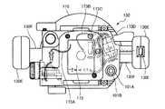
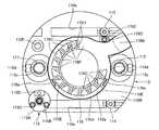
本発明の実施の形態によるルータについて図1乃至図34を参照しながら説明する。ルータ101は、図1に示すようにベース110と本体130と刃物151とを備えている。ベース110は所定の厚みを有し、一方の面110Aは図示せぬ被削材上を摺動する摺動面をなしている。摺動面をなす一方の面110Aに対する他方の面110Bの略中央の位置には、図示せぬ被削材に対して摺動面が摺動しているときの被削材側へ向けて、即ち、他方の面110Bから一方の面110Aへ向けて窪んだ略円柱形状の凹部110aが形成されている。凹部110aは、後述のダストガイド176を収容可能であり、反被削材側たるベース110の他方の面110Bの側へ開口する。当該開口する部分を画成するベース110の部分は開口部をなし、開口部を含む開口部近傍のベース110の部分はダストガイド収容部をなす。  A router according to an embodiment of the present invention will be described with reference to FIGS. Therouter 101 includes abase 110, amain body 130, and acutter 151 as shown in FIG. Thebase 110 has a predetermined thickness, and onesurface 110A forms a sliding surface that slides on a work material (not shown). At the substantially central position of theother surface 110B with respect to the onesurface 110A forming the sliding surface, toward the work material side when the sliding surface slides with respect to the work material (not shown), That is, a substantiallycylindrical recess 110a that is recessed from theother surface 110B toward the onesurface 110A is formed. Therecess 110a can accommodate adust guide 176, which will be described later, and opens to theother surface 110B side of the base 110 on the side opposite to the work material. The portion of the base 110 that defines the opening portion forms an opening, and the portion of the base 110 in the vicinity of the opening including the opening forms a dust guide housing portion.

開口部の略中央位置、即ち略円柱形状をした凹部110aの軸心の位置には、ベース貫通孔110bが形成されている。ベース貫通孔110bは、ベース110の一方の面110Aと他方の面110Bとを結ぶ方向に貫通しており、その径は後述の刃物151が同方向において通過可能な程度の大きさになっている。  A base through-hole 110b is formed at the approximate center position of the opening, that is, the position of the axial center of the substantiallycylindrical recess 110a. The base through-hole 110b penetrates in a direction connecting the onesurface 110A and theother surface 110B of thebase 110, and has a diameter that allows ablade 151 described later to pass in the same direction. .

ダストガイド収容部であって後述のダストガイド176の排出口176Bに対向するベース110の位置には、図23に示されるように傾斜面110Cが設けられている。傾斜面110Cは、ダストガイド収容部の凹部の底面からベース110の他方の面110B、即ち、ベース110の反被削材側の面へ向けて傾斜しており、後述のように、切粉をダストガイド176の内周面176Cにより画成される空間からダストガイド176の排出口176Bを通して、ベース110の反被削材の面側、即ち、他方の面110B側へ排出することができるように構成されている。  As shown in FIG. 23, aninclined surface 110C is provided at the position of the base 110 that is a dust guide accommodating portion and faces adischarge port 176B of adust guide 176 described later. Theinclined surface 110C is inclined from the bottom surface of the concave portion of the dust guide housing portion toward theother surface 110B of thebase 110, that is, the surface of the base 110 on the side opposite to the work material. The space defined by the innerperipheral surface 176C of thedust guide 176 can be discharged through thedischarge port 176B of thedust guide 176 to the surface side of the anti-work material of thebase 110, that is, theother surface 110B side. It is configured.

ベース110の反被削材側、即ち、他方の面110B側であってダストガイド収容部の外方の直径方向の位置には、図19に示されるように、コラム挿入凹部110cが形成されている。コラム挿入凹部110cは略円柱形状をなし、反被削材側から被削材側に向けて、即ち、ベース110の他方の面110Bから一方の面110Aに向けてベース110を貫通せずに所定の深さで形成されている。コラム挿入凹部110cには、平行に配置された円筒状のコラム111、112の一端が挿入されている。コラム111、112は円柱部材に相当する。  As shown in FIG. 19, acolumn insertion recess 110c is formed at a position in the diameter direction on the side opposite to the work material of thebase 110, that is, on theother surface 110B side and outside the dust guide housing portion. Yes. Thecolumn insertion recess 110c has a substantially cylindrical shape, and is predetermined from the opposite work material side toward the work material side, that is, without penetrating the base 110 from theother surface 110B of the base 110 to the onesurface 110A. It is formed with a depth of. One end ofcylindrical columns 111 and 112 arranged in parallel is inserted into thecolumn insertion recess 110c.Columns 111 and 112 correspond to cylindrical members.

コラム挿入凹部110cを画成するベース110の部分であってダストガイド収容部に最も近い位置に対するコラム挿入凹部110cの直径方向の位置には、それぞれピン挿入穴110d、110dが形成されている。ピン挿入穴110d、110dは、図1又は図19におけるベース110の左右側面からコラム挿入凹部110cの半径方向内方へ向けて形成されており、それぞれ1本ずつ図示せぬピンが挿入されている。図示せぬピンがコラム挿入凹部110cに挿入されたコラム111、112の一端部を図19の左方向又は右方向から押圧することにより、一対のコラム111、112はその一端がベース110に固定されベース110に対して移動不能となり、ベース110の反被削材側である他の面から垂直に起立した状態となっている。  Pin insertion holes 110d and 110d are formed at positions in the diameter direction of thecolumn insertion recess 110c that are portions of the base 110 that define thecolumn insertion recess 110c and are closest to the dust guide housing portion. Thepin insertion holes 110d and 110d are formed from the left and right side surfaces of the base 110 in FIG. 1 or FIG. 19 toward the inside in the radial direction of thecolumn insertion recess 110c, and one pin (not shown) is inserted. . A pair ofcolumns 111 and 112 are fixed to the base 110 at one end by pressing one end of thecolumns 111 and 112 inserted into thecolumn insertion recess 110c from the left or right direction in FIG. Thebase 110 becomes immovable with respect to thebase 110 and stands upright from the other surface of the base 110 on the side opposite to the work material.

また、ベース110のダストガイド収容部を間に挟んで図1の紙面の表寄り及び裏寄りの位置には、図19に示されるように、ベース110の略左右方向に直線状に一対の溝110e、110eが形成されている。一対の溝110e、110eは平行に形成されており、一対の溝110e、110eの所定の位置には固定ネジ113、114が設けられている。被削材の端面と当接する当接面を有する図示せぬ2本のL字状のガイドを一対の溝110e、110eにそれぞれ挿入して、固定ネジ113、114で図示せぬガイドをベース110に固定することにより、被削材に直線的な溝を切削する作業を行うことができるように構成されている。  Further, as shown in FIG. 19, a pair of grooves linearly extending substantially in the left-right direction of the base 110 are provided at positions near the front and back of the paper surface of FIG. 110e and 110e are formed. The pair ofgrooves 110e and 110e are formed in parallel, and fixingscrews 113 and 114 are provided at predetermined positions of the pair ofgrooves 110e and 110e. Two L-shaped guides (not shown) having contact surfaces that contact the end surfaces of the work material are inserted into the pair ofgrooves 110e and 110e, respectively, and the guides (not shown) are fixed to thebase 110 by fixingscrews 113 and 114. By fixing to, it is comprised so that the operation | work which cuts a linear groove | channel on a work material can be performed.

また、ベース110には、後述のボルト117の一端を挿入し固定するためのボルト固定用貫通孔110fが形成されている。ボルト固定用貫通孔110fは、ベース110の被削材側である一方の面110Aと反被削材側である他方の面110Bとを結ぶ方向にベース110を貫通している。一方ボルト117の一端よりの所定の位置には、図5に示されるように、段部117Aが設けられている。ボルト固定用貫通孔110fには、後述の円柱形状のボルト117の一端が挿入され、段部117Aがボルト固定用貫通孔110fの後述の本体130に対向する位置にある開口部の部分に当接する。そして、被削材側に位置するボルト117の一端にロックナット118が螺合することにより、図5に示されるように、ボルト117がベース110に対して固定される。ボルト117は、コラム111、112に平行に且つベース110に対して垂直に起立して設けられている。  Further, thebase 110 is formed with a bolt fixing throughhole 110f for inserting and fixing one end of abolt 117 described later. The bolt fixing throughhole 110f penetrates the base 110 in a direction connecting the onesurface 110A on the work material side of thebase 110 and theother surface 110B on the anti-work material side. On the other hand, a steppedportion 117A is provided at a predetermined position from one end of thebolt 117 as shown in FIG. One end of a later-describedcolumnar bolt 117 is inserted into the bolt fixing throughhole 110f, and the steppedportion 117A abuts on a portion of the opening portion of the bolt fixing throughhole 110f at a position facing a later-describedmain body 130. . Then, thelock nut 118 is screwed to one end of thebolt 117 located on the work material side, whereby thebolt 117 is fixed to the base 110 as shown in FIG. Thebolt 117 is provided so as to stand parallel to thecolumns 111 and 112 and perpendicular to thebase 110.

また、ベース110には、後述のストッパポール165の一端が当接可能なストッパポール当接位置調節手段115が設けられている。ストッパポール当接位置調節手段115は、図4、図19に示されるように、ターンテーブル部115Aと、複数の突出部115B、115Cと、固定手段115Dとを備える。ターンテーブル部115Aは、図19に示されるように、本体130からベース110へ向う方向で見た形状が略円形をなしており、その軸心がベース110の摺動面たる一方の面110Aに対して垂直をなし回転軸となるようにベース110に回転可能に支承されている。  Further, thebase 110 is provided with a stopper pole abutting position adjusting means 115 that can abut one end of astopper pole 165 described later. As shown in FIGS. 4 and 19, the stopper pole contact position adjusting means 115 includes aturntable portion 115A, a plurality of projectingportions 115B and 115C, and a fixing means 115D. As shown in FIG. 19, theturntable portion 115 </ b> A has a substantially circular shape when viewed in the direction from themain body 130 toward thebase 110, and its axis is formed on onesurface 110 </ b> A that is a sliding surface of thebase 110. Thebase 110 is rotatably supported so as to be perpendicular to the rotation axis.

より具体的には、図4に示されるように、ターンテーブル部115Aの軸心位置には略円柱形状の貫通孔115aが形成されており、貫通孔115aには、ベース110から本体130へ向けて突出する円柱形状の突出部110Dが挿入されている。突出部110Dの先端には、ワッシャ115Eを介してネジ115Fが突出部110Dに同軸的に螺着されている。ワッシャ115Eは、突出部110Dの先端においてフランジ状をなし、ターンテーブル部115Aに当接することによりターンテーブル部115Aが突出部110Dから外れてしまうことを防止する。  More specifically, as shown in FIG. 4, a substantially cylindrical throughhole 115a is formed at the axial center position of theturntable 115A, and the throughhole 115a is directed from the base 110 to themain body 130. A cylindrical projectingportion 110D that projects in a protruding manner is inserted. Ascrew 115F is coaxially screwed to theprotrusion 110D via awasher 115E at the tip of theprotrusion 110D. Thewasher 115E has a flange shape at the tip of the protrudingportion 110D, and prevents theturntable portion 115A from coming off the protrudingportion 110D by coming into contact with theturntable portion 115A.

複数の突出部115B、115Cは、ターンテーブル部115Aの周方向に沿った位置であって、図19で上方を0°とし反時計方向の角度を+の角度とした場合に120°の位置と240°の位置とにそれぞれ設けられている。突出部115B、115Cはそれぞれターンテーブル部115Aから垂直に延出しており、延出長さは異なり、それぞれ所定の延出長さを有する。また、突出部115B、115Cには、図示せぬ突出部雄ネジが設けられており、突出部115B、115Cを回転させることにより突出部115B、115Cをその軸方向へターンテーブル115Aに対して螺進退するように構成されている。  The plurality of projectingportions 115B and 115C are positions along the circumferential direction of theturntable portion 115A, and are 120 ° positions when the upper direction is 0 ° and the counterclockwise angle is a positive angle in FIG. It is provided at a position of 240 °. Each of the projectingportions 115B and 115C extends vertically from theturntable portion 115A, has a different extension length, and has a predetermined extension length. Theprotrusions 115B and 115C are provided with a protrusion male screw (not shown). By rotating theprotrusions 115B and 115C, theprotrusions 115B and 115C are screwed in the axial direction with respect to theturntable 115A. It is configured to advance and retreat.

ストッパポール当接位置調節手段115が設けられているため、被削材に対して溝を段階的に切削して、最終的に深い溝を形成することが可能となっている。例えば、加工材を切削することにより60mm等の比較的深い溝を形成する場合、後述のモータたる電動機131への負荷が大きいことから1回の切削作業で形成するのは困難であるため、溝を段階的に切削して最終的に深い溝とする必要がある。  Since the stopper pole contact position adjusting means 115 is provided, it is possible to form a deep groove finally by cutting the groove in a stepwise manner on the work material. For example, when a relatively deep groove of 60 mm or the like is formed by cutting a workpiece, it is difficult to form the groove by a single cutting operation because a load on amotor 131 which is a motor described later is large. Must be cut in stages to finally form deep grooves.

このような作業の際には、まず、ストッパポール165が、ターンテーブル部115Aの上面に当接した状態で刃物151がベース110の一方の面110Aから60mm突出した状態となるように調整する。また、ターンテーブル部115Aの上面からの突出部115Bの突出量が40mmとなるよう調整し、ターンテーブル部115Aの上面からの突出部115Cの突出量が20mmとなるよう調整する。  In such an operation, first, thecutter 151 is adjusted so as to protrude 60 mm from the onesurface 110A of the base 110 while thestopper pole 165 is in contact with the upper surface of theturntable portion 115A. Further, the protrusion amount of theprotrusion 115B from the upper surface of theturntable portion 115A is adjusted to 40 mm, and the protrusion amount of theprotrusion portion 115C from the upper surface of theturntable portion 115A is adjusted to 20 mm.

そして、突出量が40mmである突出部115Bにストッパポール165を当接させた状態で20mmの溝を切削する。その後、ターンテーブル部115Aを回転させ、突出量が20mmである突出部115Cにストッパポール165を当接させ、この状態で切削作業を行うと、既に形成されている20mmの溝の底から更に20mmの深さの溝、すなわち40mmの深さの溝が形成される。次いで更にターンテーブル部115Aを回転させ、ストッパポール165をターンテーブル部115Aに上面に当接させた状態で切削をすると40mmの深さ溝の底から更に20mmの深さの溝が形成され、合計60mmの深さの溝を形成することができる。  Then, a 20 mm groove is cut in a state where thestopper pole 165 is in contact with the protrudingportion 115B having a protruding amount of 40 mm. Thereafter, theturntable 115A is rotated, and thestopper pole 165 is brought into contact with theprotrusion 115C having a protrusion amount of 20 mm. When cutting is performed in this state, 20 mm further from the bottom of the already formed 20 mm groove. A groove having a depth of 40 mm, ie, a groove having a depth of 40 mm, is formed. Next, when theturntable portion 115A is further rotated and cutting is performed with thestopper pole 165 in contact with theturntable portion 115A on the upper surface, a groove having a depth of 20mm is further formed from the bottom of the 40mm depth groove. A groove with a depth of 60 mm can be formed.

このようにベース110上面に対して突出量が異なる突出部115B、115Cを有するストッパポール当接位置調節手段115にストッパポール165下端が当接することとしたため、被削材を段階的に切削して深い溝を形成する作業を容易に行うことができるようになっている。  In this way, the lower end of thestopper pole 165 is brought into contact with the stopper pole contact position adjusting means 115 having the protrudingportions 115B and 115C having different protruding amounts with respect to the upper surface of thebase 110, so that the work material is cut in stages. An operation for forming a deep groove can be easily performed.

また、固定手段115Dは、ターンテーブル部115Aの周方向に沿った位置であって、図19で上方を0°としたときの当該0°の位置に設けられている。固定手段115Dは、図4に示されるように、ベース110の一方の面110Aと他方の面110Bとを連通するようにしてベース110に形成された固定部貫通孔110gと、固定部貫通孔110gと平行にターンテーブル部115Aを貫通するターンテーブル部固定部貫通孔115bと、雄ネジと115Gとを有している。一方、後述のストッパポール165の一端部は、その内周面に第2雌ネジが螺刻されている。  Further, the fixing means 115D is provided at a position along the circumferential direction of theturntable portion 115A, and at the position of 0 ° when the upper direction is 0 ° in FIG. As shown in FIG. 4, the fixing means 115D includes a fixing portion through-hole 110g formed in the base 110 so that the onesurface 110A and theother surface 110B of the base 110 communicate with each other, and a fixing portion through-hole 110g. The turntable part fixing part through-hole 115b which penetrates theturntable part 115A in parallel with themale screw 115G. On the other hand, a second female screw is threaded on the inner peripheral surface of one end of astopper pole 165 described later.

ベース110の一方の面110A、即ち、被削材側から固定部貫通孔110g内、ターンテーブル部固定部貫通孔115b内にこの順で雄ネジ115Gを挿入してゆき、ベース110の他方の面110Bの側において後述のストッパポール165の一端部の第2雌ネジに螺合させることにより、ストッパポール165をベース110に固定して保持することができ、後述のように、本体130に対するストッパポール165の相対的な移動量、又は、本体130に対するベース110の相対的な移動量を検出することができるように構成されている。  Themale screw 115G is inserted in this order from onesurface 110A of the base 110 into the fixed part throughhole 110g and the turntable fixed part throughhole 115b from the work material side, and the other surface of thebase 110 is inserted. Thestopper pole 165 can be fixedly held on thebase 110 by being screwed onto a second female screw at one end of astopper pole 165 described later on the side of 110B. The relative movement amount of 165 or the relative movement amount of the base 110 with respect to themain body 130 can be detected.

また、ダストガイド収容部の開口部の内周面には、図19に示されるように、2つの爪部110E、110Eが設けられている。爪部110Eは、開口部の内周面において図19の上方を0°とし時計方向の角度を+の角度とした場合に120°の位置と240°の位置とに設けられている。  Further, as shown in FIG. 19, twoclaw portions 110E and 110E are provided on the inner peripheral surface of the opening of the dust guide accommodating portion. Theclaw portion 110E is provided at a position of 120 ° and a position of 240 ° when the upper part of FIG. 19 is 0 ° and the clockwise angle is a positive angle on the inner peripheral surface of the opening.

また、ベース110の他方の面110B、即ち、反被削材側の面には、図19に示されるようなダストガイド固定ネジ176Eが螺合する雌ネジが螺刻された図示せぬ穴部が形成されている。ダストガイド固定ネジ176Eは、後述のダストガイド176に設けられた延出部176Dに形成された貫通孔176bを貫通し、当該図示せぬ穴部に螺合することにより、ダストガイド176がダストガイド収容部内に収容された状態でダストガイド176をベース110に固定するように構成されている。  Further, theother surface 110B of thebase 110, that is, the surface on the side opposite to the work material is threaded with a female screw (not shown) into which a dustguide fixing screw 176E as shown in FIG. 19 is screwed. Is formed. The dustguide fixing screw 176E passes through a throughhole 176b formed in anextension portion 176D provided in thedust guide 176, which will be described later, and is screwed into a hole portion (not shown), so that thedust guide 176 becomes a dust guide. Thedust guide 176 is configured to be fixed to the base 110 while being housed in the housing portion.

一対のコラム111、112の外周は、図1、図2に示されるように、それぞれ保護部材111A、112Aにより保護されており、一対のコラム111、112の他端側は、後述のようにコラム111、112が本体貫通孔130b、130cに挿入されることにより本体130をコラム111、112に対して摺動可能に支承している。このことにより、本体130はベース110の摺動面である一方の面110Aに対して垂直の方向に、即ち図1において上下方向に移動可能に支持されている。  The outer peripheries of the pair ofcolumns 111 and 112 are protected byprotective members 111A and 112A, respectively, as shown in FIGS. 1 and 2, and the other end of the pair ofcolumns 111 and 112 is a column as described later. Themain body 130 is slidably supported with respect to thecolumns 111 and 112 by inserting 111 and 112 into the main body throughholes 130b and 130c. As a result, themain body 130 is supported so as to be movable in a direction perpendicular to the onesurface 110A that is the sliding surface of thebase 110, that is, in the vertical direction in FIG.

本体130は、電動機131の出力軸131Aを回転可能に支持しているが、変形等によって、電動機131の出力軸131Aが位置ずれしてしまい切削精度が低下することがないよう、電動機131の受け面となる図1の本体130の下部は硬度の高い金属等の導電性の材料(例えばアルミ合金)から構成される導電性ケーシング部130Aからなる。それよりも図1の上方の部分は樹脂製ケーシング部130Bとなっている。  Themain body 130 rotatably supports theoutput shaft 131A of theelectric motor 131. However, themain body 130 receives theelectric motor 131 so that theoutput shaft 131A of theelectric motor 131 is not displaced due to deformation or the like and the cutting accuracy is not lowered. The lower portion of themain body 130 in FIG. 1 that is a surface is formed of aconductive casing portion 130A made of a conductive material such as a metal having high hardness (for example, an aluminum alloy). 1 is aresin casing portion 130B.

本体130内部であって図1に示される左右方向の略中央の位置には、電動機131が内蔵されている。電動機131からは、図1の下方、即ち、摺動面たる一方の面110Aに垂直の方向であってベース110へ向かう方向へ出力軸131A(モータ軸)が延出しており、出力軸131Aの下端には、図1に示されるように、コレットチャック132を介して刃物(ビット)151が着脱可能に装着されている。  Anelectric motor 131 is built in themain body 130 at a substantially central position in the left-right direction shown in FIG. Anoutput shaft 131A (motor shaft) extends from theelectric motor 131 in the downward direction of FIG. 1, that is, in a direction perpendicular to the onesurface 110A that is a sliding surface and toward thebase 110. As shown in FIG. 1, a cutter (bit) 151 is detachably attached to the lower end via acollet chuck 132.

刃物151は、電動機131が駆動することにより回転し、本体130の上下動により、即ち、本体130がベース110に対して接近することより、ベース110の摺動面たる一方の面110Aよりも被削材側に開口部のベース貫通孔110bから突出可能である。従って、被削材上をベース110の摺動面が摺動しているときには、開口部のベース貫通孔110bから突出する刃物151が被削材に切込み、溝等を形成することができるように構成されている。また、図1に示されるように電動機131の出力軸131Aと同軸的に遠心ファン133が設けられており、ファン風を本体130からベース110へ向う方向へと送ることができるように構成されている。  Theblade 151 rotates when theelectric motor 131 is driven, and is moved more vertically than themain body 130, that is, themain body 130 approaches thebase 110, so that theblade 151 is covered more than the onesurface 110A that is the sliding surface of thebase 110. It can project from the base throughhole 110b of the opening to the cutting material side. Therefore, when the sliding surface of the base 110 slides on the work material, theblade 151 protruding from the base throughhole 110b in the opening can be cut into the work material to form a groove or the like. It is configured. Further, as shown in FIG. 1, acentrifugal fan 133 is provided coaxially with theoutput shaft 131A of theelectric motor 131 so that the fan air can be sent in the direction from themain body 130 toward thebase 110. Yes.

電動機131は、本体130を構成する導電性ケーシング部130Aの、図3の略中央の位置に載置固定される。導電性ケーシング部130Aには、図3に示されるように、コレットチャック132を外部に露出させるための貫通孔130aが図の略中央の位置に形成されており、また、電動機131が固定されている位置の図に示される左右両端には、一対の本体貫通孔130b、130cが形成されている。一対の本体貫通孔130b、130cには、それぞれ一対のコラム111、112の他端側が導電性ケーシング部130Aに対して摺動可能に挿入されている。また、ボルト117を挿入するためのボルト挿入用貫通孔130eが形成されている。  Theelectric motor 131 is placed and fixed at a substantially central position in FIG. 3 of theconductive casing portion 130 </ b> A constituting themain body 130. As shown in FIG. 3, theconductive casing portion 130 </ b> A has a throughhole 130 a for exposing thecollet chuck 132 to the outside at a substantially central position in the drawing, and theelectric motor 131 is fixed to theconductive casing portion 130 </ b> A. A pair of main body through-holes 130b and 130c are formed at the left and right ends shown in the figure of the position. The other end sides of the pair ofcolumns 111 and 112 are inserted into the pair of main body throughholes 130b and 130c so as to be slidable with respect to theconductive casing portion 130A. Also, a bolt insertion throughhole 130e for inserting thebolt 117 is formed.

(ファン風の流れについて)
また、請求項に係る発明と無関係であるが参考のためファン風の流れについて説明する。導電性ケーシングには、図1、図3に示されるように、貫通孔130aと同軸的にファン風をベース110へ送るための略環状貫通孔130dが形成されている。略環状貫通孔130dは、図1に示されるように、ベース110の開口部の略中央位置にあるベース貫通孔110bの方向へ傾斜する本体傾斜面130Cを有しており、ファン風がベース110に到達するまでの間に図1に示されるルータ1の左右外方へ流れ出てしまうことを防止することができるように構成されている。略環状貫通孔130dはファン風排出口に相当する。
(About fan-like flow)
Although notrelated to theclaimed invention, the flow of the fan wind will be described for reference. As shown in FIGS. 1 and 3, the conductive casing is formed with a substantially annular throughhole 130d coaxial with the throughhole 130a for sending fan air to thebase 110. As shown in FIG. 1, the substantially annular throughhole 130 d has a main body inclinedsurface 130 </ b> C that is inclined toward the base throughhole 110 b at a substantially central position of the opening of thebase 110. 1 so that therouter 1 can be prevented from flowing out to the left and right outside of therouter 1 shown in FIG. The substantially annular throughhole 130d corresponds to a fan wind outlet.

一対のコラム111、112の外径は同一であるが、これに対して一対の本体貫通孔130b、130cの径は同一ではない。図3に示されるように、図の右方に形成されている一方の本体貫通孔130cの径は、図の左方に形成されている他方の本体貫通孔130bの径よりも僅かに大きい。従って、一方の本体貫通孔130cの径と一方の本体貫通孔130cに挿入されている一方のコラム112の外径との差は、他方の本体貫通孔130bの径と他方の本体貫通孔130bに挿入されている他方のコラム111の外径との差よりも大きい。更に、図5に示されるように、他方の本体貫通孔130b内には環状部材134が圧入されており、環状部材134の内径はコラム111の外径と略同一である。従って、図3の左側に形成されている他方の本体貫通孔130bの方が、右側に形成されている一方の本体貫通孔130cよりもコラム111の位置の精度が高くなるように構成されている。  The outer diameters of the pair ofcolumns 111 and 112 are the same, whereas the diameters of the pair of body throughholes 130b and 130c are not the same. As shown in FIG. 3, the diameter of one main body throughhole 130c formed on the right side of the drawing is slightly larger than the diameter of the other main body throughhole 130b formed on the left side of the drawing. Therefore, the difference between the diameter of one main body throughhole 130c and the outer diameter of onecolumn 112 inserted into one main body throughhole 130c is the difference between the diameter of the other main body throughhole 130b and the other main body throughhole 130b. It is larger than the difference from the outer diameter of the other insertedcolumn 111. Further, as shown in FIG. 5, anannular member 134 is press-fitted into the other main body throughhole 130 b, and the inner diameter of theannular member 134 is substantially the same as the outer diameter of thecolumn 111. Therefore, the other body through-hole 130b formed on the left side in FIG. 3 is configured such that the position accuracy of thecolumn 111 is higher than the one body through-hole 130c formed on the right side. .

図5に示されるように、本体130内部であって一対のコラム111、112の他端と樹脂製ケーシング部130Bの一部との間には、外径がコラム111、112の内径よりも径の小さい一対の小径コラム135が配置されている。小径コラム135の一端は樹脂製ケーシング部13Bに固定されており、他端はコラム111、112の内部に摺動挿入可能である。なお、図5においては、一対の小径コラム135のうちの1本のみが現れている。  As shown in FIG. 5, the outer diameter is larger than the inner diameter of thecolumns 111 and 112 inside themain body 130 and between the other ends of the pair ofcolumns 111 and 112 and a part of theresin casing portion 130 </ b> B. A small pair ofsmall diameter columns 135 are arranged. One end of the small-diameter column 135 is fixed to the resin casing 13B, and the other end can be slid into thecolumns 111 and 112. In FIG. 5, only one of the pair ofsmall diameter columns 135 appears.

小径コラム135の外周面上には圧縮バネ136がそれぞれ巻回されており、圧縮バネ136の一端は樹脂製ケーシングに当接し、他端はコラム111、112の他端と環状部材134の内周面とにより規定される段部に当接している。圧縮バネ136は本体130を図5の上方へ、即ち、本体130をベース110から離間させる方向へ常時付勢している。  Acompression spring 136 is wound around the outer peripheral surface of thesmall diameter column 135, one end of thecompression spring 136 abuts on the resin casing, and the other end is the other end of thecolumns 111 and 112 and the inner periphery of theannular member 134. A step defined by the surface. Thecompression spring 136 constantly urges themain body 130 upward in FIG. 5, that is, in a direction to separate themain body 130 from thebase 110.

本体130の背面であって導電性ケーシングの部分には、図2に示されるように、ロックレバー137が回動可能に設けられている。ロックレバー137はノブ部137Aと図示せぬ雄ネジが螺刻された軸部137Bとを備えており、軸部137Bは、導電性ケーシング部130Aに形成され導電性ケーシング部130A外部と一方の本体貫通孔130cとを連通し内周面に雌ネジが螺刻された図示せぬロックレバー貫通孔に螺合している。軸部137Bの先端は一方のコラム112に対し当接押圧可能である。  As shown in FIG. 2, alock lever 137 is rotatably provided on the back surface of themain body 130 and the conductive casing. Thelock lever 137 includes aknob portion 137A and ashaft portion 137B in which a male screw (not shown) is screwed. Theshaft portion 137B is formed in theconductive casing portion 130A and is formed on the outside of theconductive casing portion 130A and one main body. The throughhole 130c communicates with and engages with a lock lever through hole (not shown) in which a female screw is threaded on the inner peripheral surface. The tip of theshaft portion 137B can be pressed against the onecolumn 112.

ロックレバー137を回動させて軸部137Bの先端を一方のコラム112に対して当接押圧することにより本体130を一方のコラム112に固定することができるように構成されている。また、ロックレバー137を逆方向に回動させて軸部137Bの先端をコラム112の外周面から離間させることによって、本体130のコラム112への固定が解除される。  Themain body 130 can be fixed to the onecolumn 112 by rotating thelock lever 137 and abutting and pressing the tip of theshaft portion 137B against the onecolumn 112. Further, thelock lever 137 is rotated in the reverse direction to separate the tip end of theshaft portion 137B from the outer peripheral surface of thecolumn 112, whereby the fixing of themain body 130 to thecolumn 112 is released.

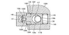
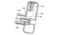
ベース110に対して垂直に起立して設けられたボルト117の、ベース110に固定されている一端部に対する他端側は、図5に示されるように本体130のボルト挿入用貫通孔130eを貫通している。ボルト挿入用貫通孔130e内に位置しているボルト117の外周面には、図6〜図9に示されるように雄ネジ部117Bが螺刻されている。ボルト挿入用貫通孔130eは、その内部がボルト117の軸方向に垂直の方向に向けて広く形成されており、当該内部に外形が略直方体形状をした係合部材138や後述の駆動部材139が設けられている。係合部材138は、このようにボルト挿入用貫通孔130eの内部が広く形成されているため、ボルト117の軸方向に垂直の方向へ移動可能である。広く形成されているボルト挿入用貫通孔130eの部分は、本体130の背面に向けて開口している。  As shown in FIG. 5, the other end side of thebolt 117, which is vertically provided with respect to thebase 110, with respect to the one end fixed to the base 110 passes through the bolt insertion through-hole 130e. is doing. Amale screw portion 117B is threaded on the outer peripheral surface of thebolt 117 positioned in the bolt insertion throughhole 130e as shown in FIGS. The bolt insertion through-hole 130e is formed so that the inside thereof is widely formed in a direction perpendicular to the axial direction of thebolt 117, and anengagement member 138 whose outer shape is a substantially rectangular parallelepiped shape and adrive member 139 described later are included therein. Is provided. Since theengagement member 138 is thus formed so that the inside of the bolt insertion through-hole 130e is wide, theengagement member 138 can move in a direction perpendicular to the axial direction of thebolt 117. A portion of the bolt insertion through-hole 130e that is widely formed opens toward the back surface of themain body 130.

係合部材138の略中央の位置には略円柱形状のボルト挿入孔138aが形成されており、ボルト挿入穴の径はボルト117の外径よりも大きい。ボルト挿入孔138aの内周面であって図7の右側の一部には、ボルト挿入孔138aの半径方向外方へ窪んだ円弧状の凹部138bが形成されており、凹部138bには雌ネジが螺刻されている。凹部138bの雌ネジには、ボルト117の雄ネジ部117Bが螺合可能である。図9に示されるように、ボルト117の雄ネジ部117Bと凹部138bの雌ネジとが係合する位置が係合位置であり、図7に示されるように、雄ネジ部117Bと雌ネジとの係合が解除される位置が係合解除位置であり、係合部材138は、係合位置と係合解除位置との間で移動可能である。  A substantially cylindricalbolt insertion hole 138 a is formed at a substantially central position of the engagingmember 138, and the diameter of the bolt insertion hole is larger than the outer diameter of thebolt 117. An arc-shapedrecess 138b that is recessed outward in the radial direction of thebolt insertion hole 138a is formed on the inner peripheral surface of thebolt insertion hole 138a on the right side of FIG. 7, and a female screw is formed in therecess 138b. Is threaded. Themale thread 117B of thebolt 117 can be screwed into the female thread of therecess 138b. As shown in FIG. 9, the position where themale thread 117B of thebolt 117 engages with the female thread of therecess 138b is the engaging position. As shown in FIG. 7, themale thread 117B and the female thread The position at which the engagement is released is the engagement release position, and theengagement member 138 is movable between the engagement position and the engagement release position.

係合部材138の外周面138Aには円柱形状の係合部材延出部138Bが設けられている。係合部材延出部138Bは、係合部材138の外周面138Aから本体130の背面の方向、即ち、図6の左方向へ向けて延出しており、その周面には略円柱形状の駆動部材139が、係合部材延出部138Bの軸と同軸的に且つ係合部材延出部138Bの軸を中心として回転可能に環装されている。駆動部材139は係合部材138の外周面138A寄りの部分が拡径部139Aとなっており、拡径部139Aの外周面には雄ネジ139Cが螺刻されている。駆動部材139は、拡径部139Aの部分までが、広く形成されているボルト挿入用貫通孔130e内に位置しており、その先の縮径部139Bは、本体130の背面から外部に突出している。  A cylindrical engagementmember extending portion 138B is provided on the outerperipheral surface 138A of theengagement member 138. The engagingmember extending portion 138B extends from the outerperipheral surface 138A of the engagingmember 138 toward the back surface of themain body 130, that is, toward the left in FIG. Themember 139 is mounted so as to be coaxial with the axis of the engagingmember extending portion 138B and rotatable about the axis of the engagingmember extending portion 138B. In thedrive member 139, a portion near the outerperipheral surface 138A of the engagingmember 138 is anenlarged diameter portion 139A, and amale screw 139C is threaded on the outer peripheral surface of theenlarged diameter portion 139A. Thedrive member 139 is located in the wide bolt insertion throughhole 130e up to theenlarged diameter portion 139A, and the reduceddiameter portion 139B of thedrive member 139 protrudes from the back surface of themain body 130 to the outside. Yes.

係合部材延出部138Bの延出端には凹部138cが形成されており、凹部138cには、ワッシャ140が環装されてネジ141が螺着されている。ワッシャ140は、係合部材延出部138Bの延出端においてフランジ状に係合部材延出部138Bの半径方向外方へ突出しており、駆動部材139の縮径部139Bが当接している。また、駆動部材139の拡径部139Aは係合部材138の外周面138Aに当接している。このことにより、係合部材延出部138Bの延出端と駆動部の縮径部139Bとは面一になっており、駆動部材139は、ワッシャ140と係合部材138の外周面138Aとの間に配置されて保持されている。ワッシャ140は当接部材に相当する。  A recessedportion 138c is formed at the extending end of the engagingmember extending portion 138B. Awasher 140 is mounted around the recessedportion 138c and ascrew 141 is screwed. Thewasher 140 protrudes outward in the radial direction of the engagingmember extending portion 138B in a flange shape at the extending end of the engagingmember extending portion 138B, and the reduceddiameter portion 139B of the drivingmember 139 is in contact therewith. Further, theenlarged diameter portion 139A of the drivingmember 139 is in contact with the outerperipheral surface 138A of the engagingmember 138. Thus, the extending end of the engagingmember extending portion 138B and the reduceddiameter portion 139B of the driving portion are flush with each other, and the drivingmember 139 is formed between thewasher 140 and the outerperipheral surface 138A of the engagingmember 138. Is held in between. Thewasher 140 corresponds to a contact member.

広く形成されているボルト挿入用貫通孔130eの一部を画成する本体130の一部であって拡径部139Aの雄ネジ139Cに対向する位置には、雌ネジ130fが螺刻されている。雌ネジ130fには駆動部材139の拡径部139Aの雄ネジ139Cが螺合しており、駆動部材139が係合部材延出部138Bを中心として回転することにより、ボルト117の軸方向へ螺進退可能に構成されている。雌ネジ130fは本体雌ネジに相当する。  Afemale screw 130f is threaded at a position that is a part of themain body 130 that defines a part of the widely formed bolt insertion throughhole 130e and faces themale screw 139C of theenlarged diameter portion 139A. . Amale screw 139C of a diameter-enlargedportion 139A of thedrive member 139 is screwed into thefemale screw 130f, and thedrive member 139 rotates around the engagingmember extending portion 138B, thereby screwing in the axial direction of thebolt 117. It is configured to be able to advance and retreat. Thefemale screw 130f corresponds to a main body female screw.

駆動部材139の縮径部139Bにはレバー部材142が環装されている。レバー部材142は、図6に示されるように、駆動部材139の回動軸に垂直の方向に延びる延出部142Aを有している。レバー部材142が環装されている駆動部材139の縮径部139Bと当該レバー部材142の部分は、レバー部材142と駆動部材139とを連結する連結部をなしており、レバー部材142の連結部の部分には内周面に雌ネジが螺刻された円柱形状の凹部142aが形成されている。凹部142aには、端部に六角形状の凹部が形成された無頭ネジ143が螺合しており、無頭ネジ143が螺進してゆき駆動部材139とレバー部材142とを押圧することによりレバー部材142を駆動部材139に対して回動不能に固定することができるように構成されている。レバー部材142は操作部材に相当する。  Alever member 142 is provided around the reduceddiameter portion 139B of thedrive member 139. As shown in FIG. 6, thelever member 142 has an extendingportion 142 </ b> A that extends in a direction perpendicular to the rotation axis of thedrive member 139. The reduceddiameter portion 139B of the drivingmember 139 and the portion of thelever member 142 around which thelever member 142 is mounted form a connecting portion that connects thelever member 142 and the drivingmember 139, and the connecting portion of thelever member 142 In this portion, a cylindricalconcave portion 142a in which a female screw is threaded is formed on the inner peripheral surface. Aheadless screw 143 having a hexagonal recess formed at the end is screwed into therecess 142a, and theheadless screw 143 is screwed to press thedrive member 139 and thelever member 142. Thelever member 142 can be fixed to thedrive member 139 so as not to rotate. Thelever member 142 corresponds to an operation member.

レバー部材142が駆動部材139に対して回動不能に固定された状態のときに、作業者は延出部142Aを摘んで回動させることにより、駆動部材139を回転させボルト117の軸心に垂直の方向へ螺進退させて、係合部材138の凹部138bの雌ネジとボルト117の雄ネジ部117Bとが螺合する係合位置に係合部材138を移動させたり、係合部材138の凹部138bの雌ネジとボルト117の雄ネジ部117Bとの螺合が解除される係合解除位置に係合部材138を移動させたりすることができるように構成されている。  When thelever member 142 is fixed to thedrive member 139 in a non-rotatable manner, the operator picks and rotates theextension 142A to rotate thedrive member 139 so that thebolt 117 is axially centered. The engagingmember 138 is moved to an engaging position where the female screw of theconcave portion 138b of the engagingmember 138 and themale screw portion 117B of thebolt 117 are screwed together by moving the engagingmember 138 in the vertical direction. Theengagement member 138 can be moved to an engagement release position where the screwing of the female screw of therecess 138b and themale screw portion 117B of thebolt 117 is released.

このように、駆動部材139を回転させることにより係合部材138を係合位置から係合解除位置へと移動させたり、また、係合解除位置から係合位置へと移動させたりするようにしたため、係合解除位置において駆動部材139を回転させないようにすることにより、係合部材138を係合解除位置に維持することができる。駆動部材139の雄ネジ139Cと当該雄ネジが螺合する本体130の雌ネジ130fとは係合解除位置保持手段に相当する。  As described above, thedrive member 139 is rotated to move theengagement member 138 from the engagement position to the engagement release position, or from the engagement release position to the engagement position. By preventing thedrive member 139 from rotating at the disengagement position, theengagement member 138 can be maintained at the disengagement position. Themale screw 139C of thedrive member 139 and thefemale screw 130f of themain body 130 into which the male screw is screwed correspond to the disengagement position holding means.

本体130の背面には、図2に示されるように背面から突出する回動規制部材144が設けられている。回動規制部材144は、レバー部材142の延出部142Aの回動範囲内に設けられており、延出部142Aが回動して延出部142Aに当接することによりレバー部材142の回動を規制するように構成されている。  As shown in FIG. 2, arotation restricting member 144 that protrudes from the back surface is provided on the back surface of themain body 130. Therotation restricting member 144 is provided within the rotation range of the extendingportion 142A of thelever member 142, and thelever member 142 rotates when the extendingportion 142A rotates and contacts the extendingportion 142A. Is configured to regulate.

ここで、前述の無頭ネジ143を螺退させて駆動部材139に対してレバー部材142を回動可能とし、回動角度を調整した後に無頭ネジ143を螺進させて駆動部材139に対してレバー部材142を回動不能とすることにより、レバー部材142の延出部142Aが回動規制部材144に当接した状態のときに係合部材138が係合位置となるようにすることができ、または、延出部が回動規制部材144に当接した状態のときに係合部材138が係合解除位置となるようにすることができる。  Here, the above-mentionedheadless screw 143 is screwed back so that thelever member 142 can be rotated with respect to thedrive member 139, and after adjusting the rotation angle, theheadless screw 143 is screwed forward with respect to thedrive member 139. By making thelever member 142 non-rotatable, the engagingmember 138 is brought into the engaging position when the extendingportion 142A of thelever member 142 is in contact with therotation restricting member 144. Alternatively, theengagement member 138 can be in the disengagement position when the extended portion is in contact with therotation restricting member 144.

また、無頭ネジ143を螺退させて駆動部材139に対してレバー部材142を回動可能とし、回動角度を微調整した後に無頭ネジ143を螺進させて駆動部材139に対してレバー部材142を回動不能とすることにより、レバー部材142の延出部142Aが回動規制部材144に当接した状態のときに係合部材138が係合位置となるようにしたときに、係合部材138の凹部138bの雌ネジとボルト117の雄ネジ部117Bとの螺合の具合を微調整することができ、強く螺合しすぎたり螺合が浅すぎたりしないように微調整することができる。  Further, theheadless screw 143 is screwed back so that thelever member 142 can be rotated with respect to thedrive member 139. After the rotation angle is finely adjusted, theheadless screw 143 is screwed forward to drive the lever against thedrive member 139. By disabling themember 142, when the engagingmember 138 is brought into the engaging position when the extendingportion 142A of thelever member 142 is in contact with therotation restricting member 144, the engagingmember 138 is engaged. The degree of screwing between the female screw of theconcave portion 138b of thecoupling member 138 and themale screw portion 117B of thebolt 117 can be finely adjusted, and fine adjustment is made so that the screwing is not too tight or the screwing is not too shallow. Can do.

広く形成されているボルト挿入用貫通孔130e内であって、係合部材延出部138Bが延出する方向に対して反対の側には、図6〜図9に示されるように圧縮バネ145が設けられている。圧縮バネ145は、図6〜図9に示されるように、一端がボルト挿入用貫通孔130eを画成する本体130の部分に当接し、他端が係合部材138に当接しており、係合部材138を常時本体130の背面方向、即ち、図6の左方向へ付勢している。このため、駆動部材139の雄ネジ139Cが、その螺進退方向において当該雄ネジが螺合する雌ネジ130fに押圧された状態となっているため、螺合におけるガタが生ずることを防止することができる。この結果、レバー部材142にガタが生ずることを防止することができる。  As shown in FIGS. 6 to 9, thecompression spring 145 is disposed on the opposite side to the extending direction of the engagingmember extending portion 138 </ b> B in the bolt insertion throughhole 130 e that is formed widely. Is provided. As shown in FIGS. 6 to 9, thecompression spring 145 has one end in contact with the portion of themain body 130 that defines the bolt insertion throughhole 130e, and the other end in contact with theengagement member 138. The combinedmember 138 is constantly urged toward the back of themain body 130, that is, to the left in FIG. For this reason, since themale screw 139C of thedrive member 139 is pressed by thefemale screw 130f to which the male screw is screwed in the screw advance / retreat direction, it is possible to prevent the play from being loosened. it can. As a result, thelever member 142 can be prevented from being loose.

ボルト117の上方、即ち、ボルト117の他端側には、図5に示されるように、円筒状の軸146が接続部材147を介してボルト117に同軸的に接続されて設けられている。接続部材147は略円筒形状をなしており、内部において軸方向の一端側の空間と他端側の空間とを分離する壁部147Aが設けられている。壁部147Aには内周面に雌ネジが螺刻された貫通孔が形成されており、当該雌ネジには雄ネジ148が螺合している。雄ネジ148は、ボルト117の他端に形成され内周面に雌ネジが形成された凹部の当該雌ネジに螺合することにより、接続部材147とボルト117とを一体回転可能に連結している。  As shown in FIG. 5, acylindrical shaft 146 is coaxially connected to thebolt 117 via a connectingmember 147 above thebolt 117, that is, on the other end side of thebolt 117. The connectingmember 147 has a substantially cylindrical shape, and is provided with awall portion 147A that separates a space on one end side in the axial direction and a space on the other end side in the inside. Thewall portion 147A is formed with a through hole in which a female screw is threaded on the inner peripheral surface, and amale screw 148 is screwed into the female screw. Themale screw 148 is coupled to the connectingmember 147 and thebolt 117 so as to be integrally rotatable by being screwed to the female screw of the recess formed on the other end of thebolt 117 and having a female screw formed on the inner peripheral surface. Yes.

軸146は、図5に示すように、コラム111、112の軸方向に平行の方向へ向けて本体130の樹脂製ケーシング部130Bに形成された円柱形状の挿通孔130gに挿通している。軸146の一端の周面には雄ネジ146Aが螺刻されており、一方、接続部材147の一端部の内周面には雌ネジ147aが螺刻されている。当該雌ネジ147aに雄ネジ146Aが螺合することにより、接続部材147と軸146とを一体回転可能に連結している。前述のように接続部材147とボルト117とが一体回転可能に連結されていることと相まって、軸146を回転させればボルト117が軸146と一体回転するように構成されている。  As shown in FIG. 5, theshaft 146 is inserted through acylindrical insertion hole 130 g formed in theresin casing portion 130 </ b> B of themain body 130 in a direction parallel to the axial direction of thecolumns 111 and 112. Amale screw 146A is threaded on the peripheral surface of one end of theshaft 146, while afemale screw 147a is threaded on the inner peripheral surface of one end of the connectingmember 147. When themale screw 146A is screwed into thefemale screw 147a, the connectingmember 147 and theshaft 146 are coupled so as to be integrally rotatable. As described above, theconnection member 147 and thebolt 117 are coupled so as to be integrally rotatable, so that thebolt 117 is integrally rotated with theshaft 146 when theshaft 146 is rotated.

接続部材147に接続されている軸の一端に対する他端には微調整ノブ149が固着されている。微調整ノブ149は、軸146に垂直の面で切った断面が円形状をなしており、その半径は軸146の半径よりもはるかに大きい。このため、微調整ノブ149を少し回すことによってボルト117を僅かに回転させることができ、ボルト117が回転することにより係合位置にある係合部材138をボルト117の雄ネジ部117Bに対して相対的に僅かに螺進退させることができる。係合部材138はボルト挿入用貫通孔130e内においてボルト117の軸方向には移動不能であるため、係合部材138が僅かに螺進退することにより、本体130を係合部材138と一体でボルト117の軸方向へ進退させることができる。  Afine adjustment knob 149 is fixed to the other end of the shaft connected to theconnection member 147. Thefine adjustment knob 149 has a circular cross section cut by a plane perpendicular to theshaft 146, and its radius is much larger than the radius of theshaft 146. Therefore, thebolt 117 can be slightly rotated by slightly turning thefine adjustment knob 149, and theengagement member 138 in the engagement position can be moved relative to themale screw portion 117B of thebolt 117 by rotating thebolt 117. The screw can be moved back and forth relatively slightly. Since the engagingmember 138 cannot move in the axial direction of thebolt 117 in the bolt insertion through-hole 130e, the engagingmember 138 is slightly screwed back and forth, so that themain body 130 and the engagingmember 138 are integrated with the bolt. It can be moved back and forth in the axial direction of 117.

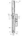
本体130の他方のコラム111が設けられた部分、即ち、図1に示される本体130の左側の部分の近傍の位置には、図10に示されるように、ストッパポール165が組み込まれたデジタル表示ユニット160が設けられている。デジタル表示ユニット160は、図1に示されるように、ビス162によって本体130に取り付けられたカバー161によってその周囲が覆われている。  A digital display in which a
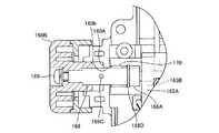
stopper pole 165 is incorporated, as shown in FIG. 10, at the position where theother column 111 of themain body 130 is provided, that is, in the vicinity of the left portion of themain body 130 shown in FIG. Aunit 160 is provided. As shown in FIG. 1, thedigital display unit 160 is covered with acover 161 attached to themain body 130 withscrews 162.

(ストッパポールについて)
請求項に係る発明と無関係であるが参考のためストッパポールについて説明する。デジタル表示ユニット160においては、互いに結合一体化されたハウジング163、164(図14)内に略板状をした長方形状のストッパポール165が、ハウジング163、164に対して移動可能に挿通支持されている。ストッパポール165の長手方向は、デジタル表示ユニット160を本体130に固着したときに、コラム111、112及びボルト117と平行の方向に指向し、後述のようにストッパポール165は、この方向へ本体130又はベース110に対して相対的に移動可能である。
(About stopper pole)
Although not related to the claimed invention, the stopper pole will be described for reference. In thedigital display unit 160, arectangular stopper pole 165 having a substantially plate shape is inserted into and supported by thehousings 163 and 164 inhousings 163 and 164 (FIG. 14) that are coupled and integrated with each other. Yes. The longitudinal direction of thestopper pole 165 is oriented in a direction parallel to thecolumns 111 and 112 and thebolt 117 when thedigital display unit 160 is fixed to themain body 130. As will be described later, thestopper pole 165 is oriented in this direction. Alternatively, it can move relative to thebase 110.

ハウジング163、164には、図14に示されるように、ハウジング163、164内部と外部とを連通する連通孔160aが形成されている。連通孔160aは、デジタル表示ユニット160を本体130に固着したときに最もベース110寄りとなるハウジング163、164の位置に形成されており、ベース110の方向に向けて開口している。連通孔160aにおいては、ストッパポール165がハウジング163、164内部から外部へと突出しており、ストッパポール165が上述のように移動し、連通孔160aから所定の長さだけベース110へ向けてストッパポール165が突出するように構成されている。  As shown in FIG. 14, thehousings 163 and 164 are formed withcommunication holes 160 a that allow the interiors of thehousings 163 and 164 to communicate with the outside. Thecommunication hole 160 a is formed at the position of thehousings 163 and 164 that are closest to the base 110 when thedigital display unit 160 is fixed to themain body 130, and opens toward thebase 110. In thecommunication hole 160a, thestopper pole 165 protrudes from the inside of thehousings 163 and 164 to the outside. Thestopper pole 165 moves as described above, and thestopper pole 165 moves from thecommunication hole 160a to thebase 110 by a predetermined length. 165 is configured to protrude.

ここでハウジング163、164内には、後述のように精密なスリットの形成されたテープ166や当該スリットを検出するための検出部171が設けられており、粉塵等のハウジング163、164内への浸入を避けるために、ハウジング163、164とハウジング163、164との接続面は図示せぬシール部材によりシールされている。また、連通孔160aの部分においても粉塵等の浸入を防止する必要があり、連通孔160aの開口の部分には、ストッパポール165に接触するフェルト167、167が設けられており、内部への粉塵等の侵入を防止可能としている。フェルト167はシール部材を構成する。  Here, in thehousings 163 and 164, as will be described later, atape 166 having a precise slit formed and adetection unit 171 for detecting the slit are provided, and dust or the like into thehousings 163 and 164 is provided. In order to avoid intrusion, the connection surfaces of thehousings 163 and 164 and thehousings 163 and 164 are sealed by a seal member (not shown). Further, it is necessary to prevent dust and the like from entering thecommunication hole 160a.Felts 167 and 167 that contact thestopper pole 165 are provided at the opening of thecommunication hole 160a. Etc. can be prevented. The felt 167 constitutes a seal member.

ストッパポール165の一部であってハウジング163、164内に位置している部分には、図11に示されるように、切欠き165aが形成されている。切欠き165aは、ストッパポール165の幅を部分的に狭くしたような形状となっており、当該部分は狭幅部165Aをなす。切欠き165aの部分には、狭幅部165Aに平行に多数の細いスリット166a(図15)が形成された薄いテープ166が掛渡されており、テーブ166の長手方向の両端は、図11に示されるように、ネジによって切欠き165aを画成するストッパポール165の部分に固着されている。テープ166のスリット166aは、テープ166の長手方向において1インチの間に150個形成されている。  As shown in FIG. 11, anotch 165 a is formed in a part of thestopper pole 165 and located in thehousings 163 and 164. Thenotch 165a has a shape in which the width of thestopper pole 165 is partially narrowed, and the portion forms anarrow width portion 165A. Athin tape 166 in which a large number ofthin slits 166a (FIG. 15) are formed in parallel with thenarrow width portion 165A is stretched over thenotch 165a, and both ends in the longitudinal direction of the table 166 are shown in FIG. As shown, it is secured to the portion of thestopper pole 165 that defines thenotch 165a with a screw. 150slits 166 a of thetape 166 are formed in one inch in the longitudinal direction of thetape 166.

ストッパポール165の狭幅部165Aであって図11に表れている部分の裏側には、図14に示されるようにラック165Bが形成されている。また、ハウジング20,21には、ハウジング163、164内部と外部とを連通する軸挿入用貫通孔160bが形成されている。  On the back side of thenarrow portion 165A of thestopper pole 165 that appears in FIG. 11, arack 165B is formed as shown in FIG. In addition, the housings 20 and 21 are formed with shaft insertion throughholes 160b that allow the insides of thehousings 163 and 164 to communicate with the outside.

軸挿入用貫通孔160bは、図11に示されるように、ストッパポール165に対して垂直の方向へ向けてハウジング163、164外部へ開口しており、軸挿入用貫通孔160b内には、軸168が当該軸挿入用貫通孔160b内で回転可能且つその軸方向に移動可能に支承されている。軸168の一端部はピニオン168Aを有しており、ストッパポール165のラック165Bに係合可能である。軸挿入用貫通孔160bがハウジング163、164外部へ開口する開口部には段部160Aが設けられており、後述のピン168Cが係合可能に構成されている。なお、図14においては、説明の便宜上ラック165Bは一部のみを図示している。  As shown in FIG. 11, the shaft insertion through-hole 160b opens to the outside of thehousings 163 and 164 in a direction perpendicular to thestopper pole 165, and the shaft insertion through-hole 160b includes ashaft 168 is supported so as to be rotatable in the shaft insertion through-hole 160b and movable in the axial direction. One end of theshaft 168 has apinion 168A and can be engaged with arack 165B of thestopper pole 165. Astep portion 160A is provided at an opening portion where the shaft insertion throughhole 160b opens to the outside of thehousings 163 and 164, and apin 168C described later is configured to be engageable therewith. In FIG. 14, only a part of therack 165B is shown for convenience of explanation.

軸168の他端にはノブ168Bが設けられている。ノブ168Bは、軸168に垂直に切った断面における外形輪郭が円形をなしており、その中心位置には、後述の雄ネジ169と螺合可能な雌ネジの形成された貫通孔が形成されている。貫通孔には、貫通孔の一方の開口部から雄ネジ169が螺合してゆき、貫通孔を貫通し、雄ネジの頭がノブ169に当接した状態となり、更に、貫通孔の他方の開口から突出した雄ネジ169が、軸の他端に形成され内周面に雌ネジが螺刻された図示せぬ凹部の当該図示せぬ雌ネジに螺合することにより、ノブ169は軸168と一体で回転可能且つ軸方向に移動可能となっている。また、軸168の長手方向における略中央の位置には、図13に示されるように、軸168の直径方向へ突出する円柱形状のピン168Cが設けられている。  Aknob 168B is provided at the other end of theshaft 168. Theknob 168B has a circular outer contour in a cross section cut perpendicular to theshaft 168, and a through hole formed with a female screw that can be screwed with amale screw 169 described later is formed at the center position. Yes. Themale screw 169 is screwed into the through hole from one opening of the through hole, passes through the through hole, and the head of the male screw is in contact with theknob 169. Themale screw 169 protruding from the opening is screwed into the not-shown female screw (not shown) formed on the other end of the shaft and screwed on the inner peripheral surface, so that theknob 169 has theshaft 168. It can be rotated integrally with it and can move in the axial direction. Further, as shown in FIG. 13, acylindrical pin 168 </ b> C that protrudes in the diameter direction of theshaft 168 is provided at a substantially central position in the longitudinal direction of theshaft 168.

ピニオン168Aが設けられている部分の軸168の他端寄りの端部には、図12、図13に示されるように段部168Dが設けられている。軸168の一部であってピニオン168Aよりも軸の他端寄りの位置には、圧縮バネ170が軸168の周りに巻回されている。圧縮バネ170の一端は段部168Dに当接し、他端は、ハウジング163、164の一部であって軸挿入用貫通孔160bを画成している部分に当接している。圧縮バネ170は、常時軸168を図12、図13の右方、即ち、図12、図13に示されるようにラック165Bにピニオン168Aが重なって係合するピニオン168Aの係合位置となる方向へ付勢している。  As shown in FIGS. 12 and 13, astep 168 </ b> D is provided at the end near the other end of theshaft 168 where thepinion 168 </ b> A is provided. Acompression spring 170 is wound around theshaft 168 at a position that is a part of theshaft 168 and closer to the other end of the shaft than thepinion 168A. One end of thecompression spring 170 is in contact with thestep portion 168D, and the other end is in contact with a part of thehousings 163 and 164 that defines the shaft insertion throughhole 160b. Thecompression spring 170 always moves theshaft 168 to the right side of FIGS. 12 and 13, that is, the direction to be the engagement position of thepinion 168A in which thepinion 168A is engaged with therack 165B as shown in FIGS. Is energized.

軸168の長手方向においてノブ168Bの一部と軸挿入用貫通孔160bを画成するハウジング163、164の一部とは、ノブ168Bに対して外部から本体130の外方へ引張る力が加わっていないときには、図11に示されるように互いに当接している。このときピニオン168Aは、ラック165Bと係合する係合位置にあり、ノブ168Bを回転させることにより、ストッパポール165をその長手方向へ移動させて、ストッパホールの位置を微調整することができるように構成されている。  In the longitudinal direction of theshaft 168, a part of theknob 168B and a part of thehousings 163 and 164 that define the shaft insertion throughhole 160b are subjected to a pulling force to theknob 168B from the outside to the outside of themain body 130. When not, they are in contact with each other as shown in FIG. At this time, thepinion 168A is in an engagement position where it engages with therack 165B. By rotating theknob 168B, thestopper pole 165 can be moved in the longitudinal direction so that the position of the stopper hole can be finely adjusted. It is configured.

ノブ168Bに対して外部から本体130の外方へ引張る力が加わることにより、ノブ168Bが図12に示されるように図の左方向に移動させられているときには、軸168の長手方向においてノブ168Bの一部と軸挿入用貫通孔160bを画成するハウジング163、164の一部とは互いに当接しておらず、ピニオン168Aは、ラック165Bと係合していない非係合位置にある。このため、ノブ168Bを回転させてもストッパポール165は移動しない。  When a pulling force is applied to theknob 168B from the outside to the outside of themain body 130, theknob 168B is moved in the longitudinal direction of theshaft 168 when theknob 168B is moved to the left as shown in FIG. And a part of thehousings 163 and 164 defining the shaft insertion throughhole 160b are not in contact with each other, and thepinion 168A is in a non-engagement position where it is not engaged with therack 165B. For this reason, even if theknob 168B is rotated, thestopper pole 165 does not move.

この状態のときに、ノブ168Bを回転させることにより軸168を回転させて、図12に示される状態から図13に示される状態とすると、ピン168Cが段部160Aに係合し、圧縮バネ170の付勢力に抗して軸168及びノブ168Bが図の右方向へ移動しようとすることを阻止し、ラック165Bとピニオン168Aとが係合していない状態が維持されるように構成されている。ピン168C及び段部160Aは非係合位置維持手段に相当する。  In this state, if theshaft 168 is rotated by rotating theknob 168B to change from the state shown in FIG. 12 to the state shown in FIG. 13, thepin 168C engages with thestep portion 160A, and thecompression spring 170 Theshaft 168 and theknob 168B are prevented from moving to the right in the figure against the urging force of the rack, and therack 165B and thepinion 168A are not engaged with each other. . Thepin 168C and thestep portion 160A correspond to a disengagement position maintaining unit.

図14に示されるように、ハウジング163、164内であってストッパポール165の切欠き165aに掛渡されたテープ166の位置には、ストッパポール165と一体に移動するテープ166の移動量を検出することによりストッパポール165の移動量を検出するための光電方式の検出部171が設けられている。検出部171は、図14に示されるように、テープ166をその厚さ方向において挟むようにして配置されており、テープ166の一方の側に光の照射部171Aが設けられ、テープ166の他方の側に光の受光部171Bが設けられている。照射部171Aと受光部171Bのセットは計2セット設けられ、1/4周期位相をずらして配置されており、テープ166の移動量のみならず、テープ166が図14に示される上方向に移動したのか下方向へ移動したのかを検出できるように構成されている。  As shown in FIG. 14, the amount of movement of thetape 166 that moves integrally with thestopper pole 165 is detected at the position of thetape 166 in thehousings 163 and 164 and spanned on thenotch 165 a of thestopper pole 165. Thus, aphotoelectric detection unit 171 for detecting the amount of movement of thestopper pole 165 is provided. As shown in FIG. 14, thedetection unit 171 is arranged so as to sandwich thetape 166 in the thickness direction, and alight irradiation unit 171A is provided on one side of thetape 166, and the other side of thetape 166 is provided. Is provided with alight receiving portion 171B. A total of two sets of theirradiation unit 171A and thelight receiving unit 171B are provided and are arranged with a ¼ period phase shifted, and thetape 166 moves upward as shown in FIG. 14 as well as the movement amount of thetape 166. It is configured to detect whether it has been moved or moved downward.

図11に示されるように、ハウジング163、164内であって、ストッパポール165に対向する位置には板バネ172が設けられている。板バネ172は、円弧状に湾曲され更にその湾曲された円弧の略中央位置をその円弧の半径方向に押圧することにより2箇所で円弧状に湾曲した形状をなしている。板バネ172は当該略中央位置とその両端の位置とにおいてハウジング163、164に支持されており、2個所の湾曲した部分がストッパポール165に当接することにより、常時ストッパポール165の長手方向に略垂直の方向からストッパポール165を押圧する。板バネ172が常時ストッパポール165を押圧するため、ストッパポール165がハウジング163、164内においてガタつくことを防止することができる。板バネ172は押圧手段に相当する。  As shown in FIG. 11, aleaf spring 172 is provided in thehousing 163, 164 at a position facing thestopper pole 165. Theleaf spring 172 is curved in an arc shape, and has a shape curved in an arc shape at two locations by pressing substantially the center position of the curved arc in the radial direction of the arc. Theleaf spring 172 is supported by thehousings 163 and 164 at the substantially central position and the positions of both ends thereof, and two curved portions abut against thestopper pole 165, so that theleaf spring 172 is always substantially in the longitudinal direction of thestopper pole 165. Thestopper pole 165 is pressed from the vertical direction. Since theleaf spring 172 always presses thestopper pole 165, thestopper pole 165 can be prevented from rattling in thehousings 163 and 164. Theleaf spring 172 corresponds to a pressing unit.

(デジタル表示ユニットについて)
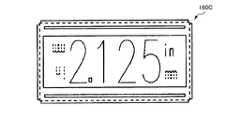
請求項に係る発明と無関係であるが参考のためデジタル表示ユニットについて説明する。デジタル表示ユニット160の正面には、図10に示すように表示部160Bが設けられており、この表示部160Bには、ストッパポール165の移動量をデジタル表示するためのLCD(液晶表示装置)160Cと、その周囲に配されたライトON/OFFスイッチ160D、零設定スイッチ160E、及び切替/TABLEスイッチ160Fとが設けられている。
(About digital display unit)
Although not related to the claimed invention, a digital display unit will be described for reference. Adisplay unit 160B is provided on the front surface of thedigital display unit 160 as shown in FIG. 10, and an LCD (liquid crystal display device) 160C for digitally displaying the amount of movement of thestopper pole 165 is provided on thedisplay unit 160B. And a light ON /OFF switch 160D, a zerosetting switch 160E, and a switch /TABLE switch 160F arranged around the switch.

ライトON/OFFスイッチ160Dは、ルータ1を図34に示すようにベース110を本体130に対して鉛直上方に位置させてルータテーブル2に取り付けた場合等において、表示部160Bが暗くて見づらいときに表示部160Bを照明するためのスイッチである。スイッチを押す毎に、「数値等の表示を一切しない表示なしの状態」と、「バックライトOFFで数値を表示する状態」と、「バックライトONで数値を表示する状態」との3つの状態にこの順で変わるように構成されている。零設定スイッチ160Eは、LCD160Cにデジタル表示されるストッパポール165の移動量の値を基準値である「0」にリセットするためのスイッチである。  The light ON /OFF switch 160D is used when thedisplay unit 160B is dark and difficult to see when therouter 1 is mounted on the router table 2 with the base 110 positioned vertically above themain body 130 as shown in FIG. It is a switch for illuminating thedisplay unit 160B. Each time the switch is pressed, there are three states: “a state where no numerical values are displayed”, “a state where numerical values are displayed when the backlight is turned off”, and “a state where numerical values are displayed when the backlight is turned on” It is configured to change in this order. The zerosetting switch 160E is a switch for resetting the value of the movement amount of thestopper pole 165 digitally displayed on theLCD 160C to “0” which is a reference value.

(上下逆転表示について)
請求項に係る発明と無関係であるが参考のため上下逆転表示について説明する。切替/TABLEスイッチ160Fは、切替スイッチとしての機能とTABLEスイッチとしての機能を兼備しており、これを所定時間(本実施の形態では、3秒)以上押し続けるとその機能が切り替えられる。切替スイッチとしては、LCD160Cにデジタル表示される数値たる移動量の単位を、図16、図17に示されるように「inch」又は「mm」に切り替える機能を果たし、TABLEスイッチとしては、図34に示されるように、LCD160Cにデジタル表示される数値たる移動量の上下を逆転させる機能を果たす。切替/TABLEスイッチ160Fは上下逆転表示手段に相当する。
(About upside down display)
Although not related to the claimed invention, the upside down display will be described for reference. The changeover /TABLE switch 160F has both a function as a changeover switch and a function as a TABLE switch, and the function is switched when it is continuously pressed for a predetermined time (3 seconds in the present embodiment). As the changeover switch, the function of changing the unit of the numerical movement amount digitally displayed on theLCD 160C to “inch” or “mm” as shown in FIGS. 16 and 17 is achieved. As the TABLE switch, as shown in FIG. As shown in the figure, it performs the function of reversing the movement amount, which is a numerical value digitally displayed on theLCD 160C. The switch /TABLE switch 160F corresponds to upside down display means.

デジタル表示ユニット160への電力の供給に際しては、電動機131へ電力を供給する電源回路173(図18)が共用される。図1に示される本体130の上部には、外部からの電力の供給を受けるための電源ケーブル101Aの一端部101Bが接続されており、電源回路173は、図18に示されるように、本体130内であって電源ケーブル101Aの一端部101Bが接続されている位置の近傍に配置されている。この位置に電源回路173が配置されているため、電源ケーブル101Aから供給された電力が電源回路173に入るまでの間に、本体130内においてノイズを拾ってしまうことを極力防止することができる。  When power is supplied to thedigital display unit 160, a power supply circuit 173 (FIG. 18) that supplies power to themotor 131 is shared. Oneend 101B of apower cable 101A for receiving external power supply is connected to the upper portion of themain body 130 shown in FIG. 1, and thepower supply circuit 173 has amain body 130 as shown in FIG. It is arrange | positioned in the vicinity of the position where the oneend part 101B of 101 A of power supply cables is connected. Since thepower supply circuit 173 is arranged at this position, it is possible to prevent as much as possible that noise is picked up in themain body 130 before the power supplied from thepower supply cable 101A enters thepower supply circuit 173.

電源回路173からはコード173Aがデジタル表示ユニット160へ至るまで延出しており、所定の電圧に変換されて、デジタル表示ユニット160へ電力供給される。また、電源回路173からはコード173Bがコネクタ173Cを介して電動機131へ至るまで延出しており、所定の電圧に変換されて電動機131へ電力供給される。電動機131へ電力を供給するためのコード173Bの途中には、ON/OFFスイッチ173Dが設けられており、スイッチ173DをONにすることにより電動機131の駆動が開始される。スイッチ173DをOFFにすることにより、電動機131の駆動が停止するように構成されている。また、ストッパポール165に対向する本体130の導電性ケーシング部130Aの位置には、図1に示されるように、ストッパポール165を一時的に本体130に対して移動不能とするためのノブ130Dが設けられている。  Thecord 173A extends from thepower supply circuit 173 to thedigital display unit 160, is converted into a predetermined voltage, and is supplied to thedigital display unit 160. Further, acord 173B extends from thepower supply circuit 173 to theelectric motor 131 via theconnector 173C, is converted into a predetermined voltage, and is supplied to theelectric motor 131. An ON /OFF switch 173D is provided in the middle of thecord 173B for supplying power to theelectric motor 131, and the driving of theelectric motor 131 is started by turning on theswitch 173D. By turning off theswitch 173D, the drive of theelectric motor 131 is stopped. Further, at the position of theconductive casing portion 130A of themain body 130 facing thestopper pole 165, as shown in FIG. 1, aknob 130D for temporarily disabling thestopper pole 165 relative to themain body 130 is provided. Is provided.

(ハンドルについて)
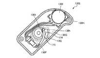
請求項に係る発明と無関係であるが参考のためハンドルについて説明する。図1に示される本体130の左右両端にはハンドル130E、130Eが設けられている。より具体的には、本体130を構成する導電性ケーシング部130Aの図1に示される左右両端の位置には、本体130の左右方向外方へ延出する本体突出部130F、130Fが設けられており、ハンドル130E、130Eは、本体突出部130F、130Fの先端に本体突出部130F、130Fに対してそれぞれ回動可能に支承されて設けられている。ハンドル130Eは略直方体形状をなしており、内部が中空でハンドル内空間130Gが形成されており、本体突出部130Fの突出方向に垂直な面で切った断面は、図24、図25に示されるように、長方形の長手方向の一端側における2つの角のうちの1つの角を曲線としたような形状をなしている。
(About the handle)
Although not related to the claimed invention, the handle will be described for reference.Handles 130E and 130E are provided at the left and right ends of themain body 130 shown in FIG. More specifically,main body protrusions 130F and 130F that extend outward in the left-right direction of themain body 130 are provided at the left and right end positions shown in FIG. 1 of theconductive casing portion 130A constituting themain body 130. Thehandles 130E and 130E are provided at the front ends of themain body protrusions 130F and 130F so as to be rotatable with respect to themain body protrusions 130F and 130F, respectively. Thehandle 130E has a substantially rectangular parallelepiped shape, is hollow inside and has a handleinner space 130G, and cross sections cut by a plane perpendicular to the protruding direction of the mainbody protruding portion 130F are shown in FIGS. In this way, one of the two corners on one end side in the longitudinal direction of the rectangle is curved.

当該2つの角のうちの曲線とされていない方の角の部分には、図24、図25に示されるように、ハンドル130Eの外方であって当該略長方形の長辺に略垂直の方向に突出する突出部130Hが設けられている。ハンドル130Eは、作業者の手によって図29、図30に示されるように把持される。このとき、作業者の人差し指の側面が突出部130Hに当接することによって、作業者の手に対して把持されているハンドル130Eの位置が、ハンドル130Eの長手方向へ移動することを防止することができる。  Of the two corners, the portion of the corner that is not a curve, as shown in FIG. 24 and FIG. 25, is the direction outside thehandle 130E and substantially perpendicular to the long side of the substantially rectangular shape. A projectingportion 130H that projects is provided. Thehandle 130E is gripped by the operator's hand as shown in FIGS. At this time, it is possible to prevent the position of thehandle 130E gripped with respect to the operator's hand from moving in the longitudinal direction of thehandle 130E by the side surface of the operator's index finger coming into contact with theprotrusion 130H. it can.

(速度可変ダイヤルについて)
請求項に係る発明と無関係であるが参考のため速度可変ダイヤルについて説明する。突出部130H近傍のハンドル130Eの位置であって、ハンドル130Eを作業者が手で把持したときに親指で操作可能なハンドル130Eの位置、即ち、図24、図25に示されるように本体突出部130Fの突出方向に垂直な面で切った断面形状である略長方形の角のうちの前述のように1つの角を曲線とした部分の位置には、電動機131の回転速度を調整可能な速度可変ダイヤル130Iが設けられている。速度可変ダイヤル130Iは可変抵抗器により構成されており、図24、図25に示されるように円形状をなし、その軸心を回転軸としてハンドル130Eに対して回転可能に支承され、その回転軸は本体突出部130Fの突出方向に平行である。
(About variable speed dial)
Although not related to the claimed invention, the speed variable dial will be described for reference. The position of thehandle 130E in the vicinity of theprotrusion 130H, and the position of thehandle 130E that can be operated with the thumb when the operator grips thehandle 130E with his / her hand, that is, as shown in FIGS. A variable speed capable of adjusting the rotational speed of theelectric motor 131 at the position of the curved portion of one of the substantially rectangular corners having a cross-sectional shape cut by a plane perpendicular to the protruding direction of 130F. A dial 130I is provided. The variable speed dial 130I is composed of a variable resistor and has a circular shape as shown in FIGS. 24 and 25. The variable speed dial 130I is rotatably supported with respect to thehandle 130E with its axis as a rotation axis. Is parallel to the protruding direction of the mainbody protruding portion 130F.

速度可変ダイヤル130Iは、図24、図25に示されるように、大部分がハンドル130Eの内部に収容されており、その周面の一部のみがハンドル130E外部に露出されている。外部に露出している速度可変ダイヤル130Iの部分はハンドル130Eの外形の輪郭よりも内方に位置しており、ハンドル130Eの外形の輪郭から突出していない。このため、作業者が誤って速度可変ダイヤル130Iを回転させてしまうことを防止することができる。  As shown in FIGS. 24 and 25, most of the variable speed dial 130I is accommodated inside thehandle 130E, and only a part of the peripheral surface is exposed to the outside of thehandle 130E. The portion of the variable speed dial 130I exposed to the outside is located inward of the outline of thehandle 130E and does not protrude from the outline of thehandle 130E. For this reason, it is possible to prevent the operator from rotating the speed variable dial 130I by mistake.

本体突出部130Fは、図27に示されるように、円柱の一部を切欠いた形状をしている。切欠かれた部分である円柱切欠き部130iは、円柱の軸心を中心として90°の扇形の部分であり、軸方向に沿って切欠かれた形状となっている。一方、ハンドル130Eの側には、円柱切欠き部130iの円弧の部分を補うような形状の円弧状部130Jがハンドル130Eから突出して設けられており、円弧状部130Jが本体突出部130Fに同軸的に配置されることにより、図24〜図26に示されるように、本体突出部130Fと円弧状部130Jとの間に本体突出部内空間130hが画成されている。  As shown in FIG. 27, the mainbody protruding portion 130F has a shape in which a part of a cylinder is cut out. Thecylindrical cutout portion 130i, which is a cutout portion, is a fan-shaped portion of 90 ° with the axial center of the cylinder as the center, and has a shape cutout along the axial direction. On the other hand, on the side of thehandle 130E, anarcuate portion 130J shaped to compensate for the arc portion of thecylindrical notch 130i is provided so as to protrude from thehandle 130E, and thearcuate portion 130J is coaxial with the mainbody protruding portion 130F. Accordingly, as shown in FIGS. 24 to 26, a main body protruding portioninner space 130h is defined between the mainbody protruding portion 130F and thearcuate portion 130J.

本体突出部130Fの円柱切欠き部130iには、絶縁性の材料により構成される絶縁部材174が設けられている。絶縁部材174は、図27に示されるように、円柱切欠き部130iの形状に倣った形状をしており、円柱切欠き部130iを覆うように設けられている。円柱切欠き部130iに対向する本体130の樹脂製ケーシング部130Bの部分には、コード175が挿通されるコード挿通孔130mが形成されている。  An insulatingmember 174 made of an insulating material is provided at thecylindrical cutout portion 130i of the mainbody protruding portion 130F. As shown in FIG. 27, the insulatingmember 174 has a shape that follows the shape of thecylindrical notch 130i, and is provided so as to cover thecylindrical notch 130i. Acord insertion hole 130m through which thecord 175 is inserted is formed in a portion of theresin casing portion 130B of themain body 130 facing thecylindrical notch portion 130i.

一方、本体突出部130Fに対向するハンドル130Eの部分には、ハンドル内空間130Gとハンドル130Eの外部とを連通するハンドル連通孔130jが形成されている。絶縁部材174は、その一部がハンドル連通孔130j内に突出しており、ハンドル130Eの回動方向におけるハンドル連通孔130jの一端及び他端を画成するハンドル130Eの部分にそれぞれ当接可能である。このように、絶縁部材174が当該ハンドル130Eの部分に当接することにより、ハンドル130Eの回動が規制されるように構成されている。ハンドル連通孔130jに対向する本体突出部内空間130hの部分は本体突出部連通孔130k(図26)を構成する。  On the other hand, ahandle communication hole 130j that connects the handleinner space 130G and the outside of thehandle 130E is formed in a portion of thehandle 130E facing themain body protrusion 130F. A part of the insulatingmember 174 protrudes into thehandle communication hole 130j, and can be brought into contact with a portion of thehandle 130E that defines one end and the other end of thehandle communication hole 130j in the rotation direction of thehandle 130E. . As described above, the rotation of thehandle 130E is restricted by the insulatingmember 174 coming into contact with thehandle 130E. The portion of the main body protrusioninner space 130h that faces thehandle communication hole 130j constitutes a main bodyprotrusion communication hole 130k (FIG. 26).

ハンドル内空間130Gと本体突出部内空間130hとは、ハンドル連通孔130jと本体突出部連通孔130kとを介して連通しており、その一部は、ハンドルの回動位置に関わらず連通した状態が維持されている。前述のようにハンドル130Eは本体突出部130Fに対して回動可能であるが、ハンドル130Eの回動に伴いハンドル内空間130Gと本体突出部内空間130hとが非連通状態とならないようにする必要がある。後述のようにハンドル内空間130Gと本体突出部内空間130hとに渡ってコード175(図24等)が配置されるためである。  The handleinner space 130G and the main body projecting portioninner space 130h communicate with each other via thehandle communication hole 130j and the main body projectingportion communication hole 130k, and a part of theinner space 130G communicates regardless of the rotation position of the handle. Maintained. As described above, thehandle 130E is rotatable with respect to themain body protrusion 130F. However, it is necessary to prevent the handleinner space 130G and the main body protrusioninner space 130h from being disconnected from each other as thehandle 130E rotates. is there. This is because the cord 175 (FIG. 24, etc.) is arranged across the handleinner space 130G and the main body protruding portioninner space 130h as will be described later.

このため、ハンドル130Eの回動方向におけるハンドル連通孔130jの一端には、図24、図25に示されるように、一端の位置よりもハンドル130Eの回動方向へ窪んだ凹部130lが形成されている。凹部130lを介してハンドル内空間130Gと本体突出部内空間130hとが常時連通状態となっており、凹部130lには、ハンドル130Eが回動されてハンドル連通孔130jの一端に絶縁部材174が当接するときに、コード175が一時的に退避可能に構成されている。  Therefore, at one end of thehandle communication hole 130j in the rotation direction of thehandle 130E, as shown in FIGS. 24 and 25, a recess 130l that is recessed in the rotation direction of thehandle 130E from the position of one end is formed. Yes. The handleinner space 130G and the main body protruding portioninner space 130h are always in communication with each other via the recess 130l. Thehandle 130E is rotated in the recess 130l so that the insulatingmember 174 abuts one end of thehandle communication hole 130j. Sometimes, thecode 175 is configured to be temporarily retractable.

コード175は、一端が電動機131(図1)に接続され、コード挿通孔130mを通り絶縁部材174を跨ぐようにして本体突出部内空間130h内を通り本体突出部連通孔130kとハンドル連通孔130jとを通り、ハンドル内空間130G内へ入り、速度可変ダイヤル130Iに接続されている。  One end of thecord 175 is connected to the electric motor 131 (FIG. 1), passes through thecord insertion hole 130m, straddles the insulatingmember 174, passes through the inside of the main body protruding portioninner space 130h, and the main body protrudingportion communication hole 130k and thehandle communication hole 130j , Enters the handleinner space 130G, and is connected to the variable speed dial 130I.

ハンドル130Eが回動可能であるため、作業者はハンドル130Eを所望の角度としてルータ1を使用することができる。ハンドル130Eが回動させる際に、ハンドル連通孔130jに凹部130lが形成されているため、ハンドル内空間130Gと本体突出部内空間130hとを常時連通状態とすることができ、コード175を通すことができる。  Since thehandle 130E is rotatable, the operator can use therouter 1 with thehandle 130E as a desired angle. Since the recess 130l is formed in thehandle communication hole 130j when thehandle 130E is rotated, the handleinner space 130G and the main body protruding portioninner space 130h can always be in communication with each other, and thecord 175 can be passed. it can.

また、上述のように、突出部130H近傍のハンドル130Eの位置であってハンドル130Eを作業者が手で把持したときに親指で操作可能なハンドル130Eの位置に、電動機131の回転速度を調整可能な速度可変ダイヤル130Iが設けられているため、刃物151で被削材に対して切込みながらその状態を目視して、電動機131を最適な回転数に調整することができる。  Further, as described above, the rotational speed of theelectric motor 131 can be adjusted to the position of thehandle 130E near theprotrusion 130H and to the position of thehandle 130E that can be operated with the thumb when the operator grips thehandle 130E by hand. Since the variable speed dial 130I is provided, the state can be visually observed while cutting the work material with theblade 151, and theelectric motor 131 can be adjusted to an optimum rotational speed.

(ダストガイドについて)
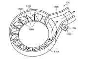
請求項に係る発明と無関係であるが参考のためダストガイドについて説明する。導電性ケーシング部130Aの略環状貫通孔130dに対向するベース110の位置に配置され前述のダストガイド収容部に収容されているダストガイド176は、図20に示されるように、軸方向の長さの短い略円筒形状部176Aと排出口176Bとを有しており、後述のように刃物151によって被削材に対して切込んでいるときには、ダストガイド176の略円筒形状部176Aの内周面176Cは、刃物151の回転軸を中心とする半径方向外方の位置において刃物151を中心として略円形に取囲んでいる。
(Dust guide)
Although not related to the claimed invention, the dust guide will be described for reference. As shown in FIG. 20, thedust guide 176 disposed at the position of the base 110 facing the substantially annular throughhole 130 d of theconductive casing portion 130 </ b> A is accommodated in the axial direction as shown in FIG. 20. Of the substantiallycylindrical portion 176A of thedust guide 176 when it is cut into the work material by theblade 151 as will be described later. 176 </ b> C surrounds theblade 151 in a substantially circular shape at a radially outward position centered on the rotation axis of theblade 151.

ダストガイド176の略円筒形状部176Aの外周面には、図19に示されるように2つの凹部176a、176aが形成されている。凹部176a、176aは、図19に示されるように本体130からベース110へ向う方向から見て時計周り方向を+の角度とした場合に、略円筒形状部176Aの後述の排出口176Bを略45°の位置としたときの120°の位置と240°の位置とに形成されており、ダストガイド収容部の2つの爪部110E、110Eにそれぞれ係合可能である。ダストガイド176の略円筒形状部176Aはダストガイド収容部の凹部110aの内壁のほぼ全周に渡って当接しており、ダストガイド176のダストガイド収容部内における半径方向の位置決めがなされている。また、ダストガイド固定ネジ176Eによってダストガイド176をベース160に固定することで、ダストガイド176の回転が規制される構造をしている。  As shown in FIG. 19, twoconcave portions 176a and 176a are formed on the outer peripheral surface of the substantiallycylindrical portion 176A of thedust guide 176. As shown in FIG. 19, therecesses 176a and 176a form adischarge port 176B, which will be described later, of the substantiallycylindrical portion 176A by approximately 45 when the clockwise direction as viewed from the direction from themain body 130 toward thebase 110 is a positive angle. It is formed at a position of 120 ° and a position of 240 ° with respect to the position of °, and can be engaged with the twoclaw portions 110E and 110E of the dust guide housing portion, respectively. The substantiallycylindrical portion 176A of thedust guide 176 is in contact with substantially the entire circumference of the inner wall of therecess 110a of the dust guide housing portion, and thedust guide 176 is positioned in the radial direction within the dust guide housing portion. Further, thedust guide 176 is fixed to thebase 160 by the dustguide fixing screw 176E, whereby the rotation of thedust guide 176 is restricted.

また、ダストガイド176の排出口176B近傍には、図19に示されるように、延出部176Dが設けられており、延出部176Dには、貫通孔176b(図20等)が形成されている。ダストガイド176がダストガイド収容部に収容されたときに、2つの爪部110E、110Eが2つの凹部176a、176aに一つずつ係合し、略円筒形状部176Aの延出部176Dの貫通孔176bをダストガイド固定ネジ176Eが貫通し、ダストガイド固定ネジ176Eが前述のベース110に形成された図示せぬ穴部に螺合することによってダストガイド176がベース110に固定される。  Further, as shown in FIG. 19, anextension 176D is provided in the vicinity of thedischarge port 176B of thedust guide 176, and a through-hole 176b (FIG. 20 and the like) is formed in theextension 176D. Yes. When thedust guide 176 is accommodated in the dust guide accommodating portion, the twoclaw portions 110E and 110E engage with the twoconcave portions 176a and 176a one by one, and the through hole of the extendingportion 176D of the substantiallycylindrical portion 176A A dustguide fixing screw 176E passes through 176b, and the dustguide fixing screw 176E is screwed into a hole (not shown) formed in thebase 110, whereby thedust guide 176 is fixed to thebase 110.

軸方向における一端であって本体130に対向する上端部には、ダストガイド176の略円筒形状部176Aの周面から半径方向へ延出する上壁部176Fが設けられている。上壁部176Fにおいては、図19に示されるように、ダストガイド176の略円筒形状部176Aの周方向へ略270°に渡り、軸方向に貫通する略台形状の貫通孔176cが所定間隔を隔てて計12個形成されており、貫通孔176cを通してファン風を略円筒形状部176Aの軸方向上端部から下端部へと通すことができるように構成されている。  Anupper wall portion 176F extending in the radial direction from the circumferential surface of the substantiallycylindrical portion 176A of thedust guide 176 is provided at an upper end portion that is one end in the axial direction and faces themain body 130. In theupper wall portion 176F, as shown in FIG. 19, a substantially trapezoidal through-hole 176c penetrating in the axial direction extends approximately 270 ° in the circumferential direction of the substantiallycylindrical portion 176A of thedust guide 176 at a predetermined interval. A total of twelve are formed, and the fan wind can be passed from the upper end in the axial direction of the substantiallycylindrical portion 176A to the lower end through the throughhole 176c.

上壁部176Fが設けられているため、略円筒形状部176Aの上壁部176Fの開口面積が小さくなっている。このため、後述のように刃物151が被削材に対して切込む際に生ずる切粉が、略円筒形状部176Aの内周面176Cにより画成される空間内から外部へ飛散することを極力防止することができると共にダストガイド176に図示せぬ集塵機と接続された図示せぬホースを接続して集塵しながら作業を行う際の集塵率を向上させることができるようにしている。  Since theupper wall portion 176F is provided, the opening area of theupper wall portion 176F of the substantiallycylindrical portion 176A is small. For this reason, it is as much as possible that the chips generated when thecutter 151 cuts into the work material as described later scatters from the space defined by the innerperipheral surface 176C of the substantiallycylindrical portion 176A to the outside. A dust hose connected to a dust collector (not shown) can be connected to thedust guide 176 to improve the dust collection rate when working while collecting dust.

ダストガイド176の略円筒形状部176Aの内周面176Cには第1壁部176Gと第2壁部176Hとが設けられている。第1壁部176G、第2壁部176Hは、上壁部176Fの略台形状の貫通孔と略同一形状の板状部材を、その一の角の近傍の位置であって当該一の角を挟む2つの辺の所定の位置を結ぶ直線で折り曲げたような形状をしており、第1壁部176Gは、当該折り曲げられた直線の位置を境界線として、当該折曲げられた板状部材の一方に相当し、第2壁部176Hは当該折曲げられた板状部材の他方に相当する。当該境界線を中心として第1壁部176Gの面と第2壁部176Hの面とは鈍角をなしている。  Afirst wall portion 176G and asecond wall portion 176H are provided on the innerperipheral surface 176C of the substantiallycylindrical portion 176A of thedust guide 176. Thefirst wall portion 176G and thesecond wall portion 176H are plate-like members having substantially the same shape as the substantially trapezoidal through hole of theupper wall portion 176F. Thefirst wall portion 176G has a shape that is bent along a straight line that connects a predetermined position between two sides sandwiched between thefirst wall portion 176G and the position of the bent straight line as a boundary line. Thesecond wall portion 176H corresponds to one side, and corresponds to the other of the bent plate-like members. The surface of thefirst wall portion 176G and the surface of thesecond wall portion 176H form an obtuse angle with the boundary line as the center.

第1壁部176Gは、ダストガイド176の内周面176Cの図19における時計方向へ向って、即ち、刃物151の回転駆動方向へ向かって、内周面176の軸方向の上端部から下端部へ、即ち、図19の紙面の表から裏へと傾斜している。第2壁部176Hは、ダストガイド176の内周面176Cの図19における時計方向へ向って即ち、刃物151の回転駆動方向へ向かって、且つ内周面176Cの半径方向外方へ向って、内周面176の軸方向の上端部から下端部へ、即ち、図19の紙面の表から裏へと傾斜している。  Thefirst wall portion 176G extends from the upper end portion in the axial direction to the lower end portion in the axial direction of the innerperipheral surface 176 toward the clockwise direction in FIG. 19 of the innerperipheral surface 176C of thedust guide 176, that is, toward the rotational drive direction of theblade 151. That is, it is inclined from the front to the back of the paper surface of FIG. Thesecond wall portion 176H faces the clockwise direction in FIG. 19 of the innerperipheral surface 176C of thedust guide 176, that is, toward the rotational drive direction of theblade 151 and outward in the radial direction of the innerperipheral surface 176C. The innerperipheral surface 176 is inclined from the upper end to the lower end in the axial direction, that is, from the front to the back of the paper surface of FIG.

このように第1壁部176Gと第2壁部176Hとが設けられているため、図21において矢印で示されるように、略円筒形状部176Aの内周面176C側において、略円筒形状部176Aの半径方向内方から略外方へ斜めにファン風を流すことができ、ファン風が流れる向きは刃物151の回転方向、即ち、切粉の飛散方向と一致するので、効率良く切粉を排出口176Bまでガイドすることができる。第1の壁部176Gと第2の壁部176Hは指向手段に相当する。  Since thefirst wall portion 176G and thesecond wall portion 176H are thus provided, the substantiallycylindrical portion 176A is provided on the innerperipheral surface 176C side of the substantiallycylindrical portion 176A as shown by the arrow in FIG. The fan wind can flow obliquely from the inside in the radial direction to the outside, and the direction in which the fan wind flows coincides with the direction of rotation of theblade 151, that is, the direction in which the chips are scattered. Guide to exit 176B. Thefirst wall portion 176G and thesecond wall portion 176H correspond to directing means.

排出口176Bは、図20、図21略円筒形状部176Aの周面から突出して設けられている。排出口176Bは、内部が中空になっておりファン風の流路が画成されている。ダストガイド176の略円筒形状部176Aに接続されている排出口176Bの部分は、図21に示されるように、略円筒形状部176Aの接線方向にファン風の流路が形成されるように、略円筒形状部176Aの内周面176Cに沿って当該内周面176Cにより画成される空間に対して開口しており、略円筒形状部176Aから所定距離だけ離間した位置から少し折曲がり、略円筒形状部176Aの略半径方向外方へ流路が形成されるように構成されている。  Thedischarge port 176B is provided so as to protrude from the peripheral surface of the substantiallycylindrical portion 176A of FIGS. Thedischarge port 176B is hollow inside, and a fan-like flow path is defined. As shown in FIG. 21, the portion of thedischarge port 176B connected to the substantiallycylindrical portion 176A of thedust guide 176 forms a fan-like flow path in the tangential direction of the substantiallycylindrical portion 176A. It opens to the space defined by the innerperipheral surface 176C along the innerperipheral surface 176C of the substantiallycylindrical portion 176A, and is slightly bent from a position separated by a predetermined distance from the substantiallycylindrical portion 176A. The flow path is formed substantially outward in the radial direction of thecylindrical portion 176A.

略円筒形状部176Aに接続されている排出口176Bは、図示せぬ集塵機のホースの一端を接続可能である。従って、図示せぬ集塵機を駆動させることにより、略円筒形状部176A内の切粉をダストガイド176の排出口176Bを介して集塵機に吸引することができる。  Adischarge port 176B connected to the substantiallycylindrical portion 176A can connect one end of a hose of a dust collector (not shown). Therefore, by driving a dust collector (not shown), the chips in the substantiallycylindrical portion 176A can be sucked into the dust collector through thedischarge port 176B of thedust guide 176.

また、集塵機のホースが接続されていない場合であっても、第1壁部176Gと第2壁部176Hとが設けられているため、上壁部176Fの貫通孔を通って略円筒形状部176Aの内周面176Cにより画成される空間内に入ってきたファン風を、図21、図23において矢印で示すように、略円筒形状部176Aの内周面176Cに沿って周方向へ流すことができる。このため、内周面176C近傍の位置に堆積しやすい切粉を、効果的に周方向へ飛ばすことができ、排出口176Bから排出させることができる。  Even if the dust collector hose is not connected, since thefirst wall portion 176G and thesecond wall portion 176H are provided, the substantiallycylindrical portion 176A passes through the through hole of theupper wall portion 176F. As shown by the arrows in FIGS. 21 and 23, the fan wind that has entered the space defined by the innerperipheral surface 176C is caused to flow in the circumferential direction along the innerperipheral surface 176C of the substantiallycylindrical portion 176A. Can do. For this reason, it is possible to effectively blow away chips that are likely to be deposited in the vicinity of the innerperipheral surface 176C in the circumferential direction, and can be discharged from thedischarge port 176B.

(電気的な構成及び制御について)
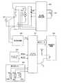
請求項に係る発明と無関係であるが参考のため電気的な構成及び制御について説明する。ルータ1の回路基板構成について、図31に示されるブロック図に基づき説明する。図31に示されるように、ルータ1の回路基板上には、マイクロプロセッサ201と、操作指示キー202と、エンコーダシステム203と、液晶表示装置204と、定速度制御装置205と、直流変換器206とが設けられている。後述のアップダウンカウンタと、アップダウンクロックと、演算処理装置と、インターフェイスコントローラユニットの各機能とは、マイクロプロセッサ201のハードウェア及びソフトウェアにより実現される。
(About electrical configuration and control)
Although not related to the claimed invention, the electrical configuration and control will be described for reference. The circuit board configuration of therouter 1 will be described based on the block diagram shown in FIG. As shown in FIG. 31, on the circuit board of therouter 1, amicroprocessor 201,operation instruction keys 202, anencoder system 203, a liquidcrystal display device 204, a constantspeed control device 205, and aDC converter 206 are provided. And are provided. Each function of an up / down counter, an up / down clock, an arithmetic processing unit, and an interface controller unit, which will be described later, is realized by hardware and software of themicroprocessor 201.

直流変換器206は前述の電源回路173である。マイクロプロセッサ201は、電動機131及び電動機131を定速度で制御する定速度制御装置205が接続された交流電源に直流変換器206を介して接続されている。定速度制御装置205には、速度可変ダイヤル130Iと、電動機131のモータの回転数を検出する回転数検出器208とが接続されている。直流変換器206は、交流電流を直流電流へ変換してマイクロプロセッサ201へ供給する。また、マイクロプロセッサ201は、操作指示キー202とエンコーダシステム203とに接続されている。マイクロプロセッサ201は、液晶表示装置204において被削材に形成される溝等の深さの値、即ち、切込み深さの値を表示するように、液晶表示装置204へ表示データを出力する。  TheDC converter 206 is thepower supply circuit 173 described above. Themicroprocessor 201 is connected via aDC converter 206 to an AC power source to which anelectric motor 131 and aconstant speed controller 205 for controlling theelectric motor 131 at a constant speed are connected. The constantspeed control device 205 is connected to a speed variable dial 130I and arotational speed detector 208 that detects the rotational speed of the motor of theelectric motor 131. TheDC converter 206 converts an alternating current into a direct current and supplies it to themicroprocessor 201. Themicroprocessor 201 is connected to theoperation instruction key 202 and theencoder system 203. Themicroprocessor 201 outputs display data to the liquidcrystal display device 204 so as to display a depth value of a groove or the like formed in the work material in the liquidcrystal display device 204, that is, a cut depth value.

液晶表示装置204は、前述のデジタル表示ユニット160の表示部160BのLCD160Cである。エンコーダシステム203は前述の検出部171であり、前述のように位相をずらして配置された2セットの照射部171Aと受光部171Bとにより、切込み深さの値のみならず、切込みの方向をも検出可能に構成されている。エンコーダは、図32に示されるように、信号Aと信号Bとの2つの信号をマイクロプロセッサ201に出力可能である。  The liquidcrystal display device 204 is theLCD 160C of thedisplay unit 160B of thedigital display unit 160 described above. Theencoder system 203 is thedetection unit 171 described above, and the two sets of theirradiation unit 171A and thelight receiving unit 171B arranged with the phases shifted as described above not only determine the cutting depth value but also the cutting direction. It is configured to be detectable. As shown in FIG. 32, the encoder can output two signals of signal A and signal B to themicroprocessor 201.

切込み深さが深くなる方向へストッパポール165が本体130に対して相対移動しているときには、図32に示されるように、信号Aが信号Bよりも90°位相が進んでいることを示しており、切込み深さが浅くなる方向へストッパポール165が本体130に対して相対移動しているときには、信号Aが信号Bよりも90°位相が遅れていることを示している。  When thestopper pole 165 moves relative to themain body 130 in the direction of increasing the depth of cut, the signal A indicates that the phase of the signal A is advanced by 90 ° with respect to the signal B, as shown in FIG. In addition, when thestopper pole 165 moves relative to themain body 130 in the direction in which the depth of cut becomes shallow, it indicates that the phase of the signal A is delayed by 90 ° from the signal B.

信号A、信号Bの立上がりと立下がりのタイミングで生ずる短いパルスを4分割パルスと呼ぶが、これは、この信号を入力するマイクロプロセッサ201内のアップダウンカウンタのアップダウンクロックとなる。  A short pulse generated at the rising and falling timings of the signals A and B is called a four-divided pulse. This is an up / down clock of an up / down counter in themicroprocessor 201 to which this signal is input.

アップダウン信号は、信号Aと信号Bとの位相の遅進により変化する信号であり、図32においては、切込み深さが深くなる方向では、信号Aが信号Bよりも90°位相が進むことによりアップダウン信号がハイレベルになり、アップダウンカウンタは、アップダウンクロックを入力する毎にインクリメントされる。切込み深さが浅くなる方向では、信号Aが信号Bよりも90°位相が遅れることによりアップダウン信号がロウレベルになり、アップダウンカウンタは、アップダウンクロックを入力する毎にデクリメントされるように構成されている。  The up / down signal is a signal that changes due to the phase delay between the signal A and the signal B. In FIG. 32, the signal A advances 90 ° in phase with respect to the signal B in the direction in which the cutting depth increases. As a result, the up / down signal becomes high level, and the up / down counter is incremented every time the up / down clock is input. In the direction in which the cutting depth becomes shallower, the up / down signal becomes low level because the signal A is delayed by 90 ° from the signal B, and the up / down counter is decremented every time the up / down clock is input. Has been.

操作指示キー202のSW1、SW2、SW3は、それぞれデジタル表示ユニット160の液晶表示装置204たる表示部160Bの周囲に配されたライトON/OFFスイッチ160D、切替/TABLEスイッチ160F、零設定スイッチ160Eである。前述のようにデジタル表示ユニット160の表示部160Bに表示される値の単位は、切替/TABLEスイッチ160FであるSW2が操作されることによりインチ法(inch)とメートル法(mm)とが切り換る。演算処理装置では、現在における状態がインチ法であるときには、アップダウンカウンタの値をインチ目盛りの長さの表示に換算する。現在における状態がメートル法であるときには、アップダウンカウンタの値をmm単位の長さの表示に換算する。  SW1, SW2, and SW3 of theoperation instruction key 202 are a light ON /OFF switch 160D, a switch /TABLE switch 160F, and a zerosetting switch 160E arranged around thedisplay unit 160B that is the liquidcrystal display device 204 of thedigital display unit 160, respectively. is there. As described above, the unit of the value displayed on thedisplay unit 160B of thedigital display unit 160 is switched between the inch method (inch) and the metric method (mm) by operating the SW2 which is the switch /TABLE switch 160F. . In the arithmetic processing unit, when the current state is the inch method, the value of the up / down counter is converted into the display of the length of the inch scale. When the current state is the metric system, the value of the up / down counter is converted into a display of length in mm.

現在における状態、即ち、インチ法であるかメートル法であるかの状態は、図示せぬ記憶手段に記憶されており、電源スイッチたるON/OFFスイッチ173DがOFFにされた後に再びONにされたときに、OFFにされる前の状態となるように構成されている。  The current state, that is, the state of the inch method or the metric method is stored in a storage means (not shown), and when the power switch ON /OFF switch 173D is turned OFF and then turned ON again. In addition, it is configured to be in a state before being turned off.

また、演算処理装置では、図示せぬ記憶装置に記憶されている「正常表示/逆表示フラグ」の状態が、正常表示の状態であるのか逆表示の状態であるのかを読出すことにより、液晶表示装置204たるデジタル表示ユニット160の表示部160BのLCD160Cに表示される数値を、正常の表示パターンコードに倣った表示とするか逆表示パターンコードに倣った表示とするか決定するように構成されている。  Further, the arithmetic processing unit reads out whether the state of the “normal display / reverse display flag” stored in a storage device (not shown) is a normal display state or a reverse display state. The numerical value displayed on theLCD 160C of thedisplay unit 160B of thedigital display unit 160 as thedisplay device 204 is configured to determine whether to display according to the normal display pattern code or to display according to the reverse display pattern code. ing.

次に、上述の構成のルータ1のマイクロプロセッサ201の動作について、図33に示されるフローチャートに基づき説明する。ON/OFFスイッチ173DがONにされると(スタート)、先ず、マイクロプロセッサ201自身のイニシャライズを行う(S1)。次に、「バックライトOFFで数値を表示する状態」とし(S2)、マイクロプロセッサ201のアップダウンカウンタの値をゼロにする(S3)。  Next, the operation of themicroprocessor 201 of therouter 1 having the above-described configuration will be described based on the flowchart shown in FIG. When the ON /OFF switch 173D is turned on (start), first, themicroprocessor 201 itself is initialized (S1). Next, it is set to “a state in which numerical values are displayed when the backlight is OFF” (S2), and the value of the up / down counter of themicroprocessor 201 is set to zero (S3).

次に、ストッパポール165の移動により生ずる信号A、信号Bの読込みの処理を開始する(S4)。先ず、信号A、信号Bの出力が変化することによりストッパポール165が移動したことを検出すると(S5:Yes)、ストッパポール165の移動方向がベース110から離間する方向か否かの判断を行う(S6)。このとき信号Aと信号Bとの組合せが00→10→11→01と変化した場合には、ベース110から離間する方向であると判断され(S6:Yes)、アップダウンカウンタに1プラスし(S8)、デジタル表示ユニット160の表示部160Bに表示される数値がインチ法か否かの判断を行う(S9)。  Next, the process of reading the signals A and B caused by the movement of thestopper pole 165 is started (S4). First, when it is detected that thestopper pole 165 has moved due to changes in the output of the signals A and B (S5: Yes), it is determined whether or not the moving direction of thestopper pole 165 is away from thebase 110. (S6). At this time, when the combination of the signal A and the signal B changes from 00 → 10 → 11 → 01, it is determined that the direction is away from the base 110 (S6: Yes), and 1 is added to the up / down counter ( In S8, it is determined whether or not the numerical value displayed on thedisplay unit 160B of thedigital display unit 160 is the inch method (S9).

信号Aと信号Bとの組合せが01→11→10→00と変化した場合には、ベース110に接近する方向であると判断され(S6:No)、アップダウンカウンタから1マイナスし(S7)、デジタル表示ユニット160の表示部160Bに表示される数値がインチ法か否かの判断を行う(S9)。信号A、信号Bの出力が変化せずストッパポール165の移動を検出できない場合には(S5:No)、デジタル表示ユニット160の表示部160Bに表示される数値がインチ法か否かの判断を行う(S9)。  When the combination of the signal A and the signal B changes from 01 → 11 → 10 → 00, it is determined that the direction is closer to the base 110 (S6: No), and 1 is subtracted from the up / down counter (S7). Then, it is determined whether or not the numerical value displayed on thedisplay unit 160B of thedigital display unit 160 is the inch method (S9). When the output of the signals A and B does not change and the movement of thestopper pole 165 cannot be detected (S5: No), it is determined whether or not the numerical value displayed on thedisplay unit 160B of thedigital display unit 160 is the inch method. Perform (S9).

図示せぬ記憶手段に記憶されている現在におけるインチ法であるかメートル法であるかの状態が、メートル法であるときには、アップダウンカウンタの値をmm単位の長さの表示に換算する(S10)。現在における状態がインチ法であるときには、アップダウンカウンタの値をインチ目盛りの長さの表示に換算する(S11)。  When the current state of the inch method or the metric system stored in the storage means (not shown) is the metric system, the value of the up / down counter is converted into a display of length in mm (S10). When the current state is the inch method, the value of the up / down counter is converted into an indication of the length of the inch scale (S11).

次に、図示せぬ記憶装置に記憶されている「正常表示/逆表示フラグ」の状態が、逆表示の状態である場合には(S12:Yes)、デジタル表示ユニット160の表示部160Bにおける切込み深さの表示を上下逆に表示させる(S14)。また、「正常表示/逆表示フラグ」の状態が、正常表示の状態である場合には(S12:No)、デジタル表示ユニット160の表示部160Bにおける切込み深さの表示を正常に表示させる(S13)。  Next, when the state of the “normal display / reverse display flag” stored in the storage device (not shown) is the reverse display state (S12: Yes), the cut in thedisplay unit 160B of thedigital display unit 160 is performed. The depth display is displayed upside down (S14). When the “normal display / reverse display flag” is in the normal display state (S12: No), the display of the depth of cut in thedisplay unit 160B of thedigital display unit 160 is displayed normally (S13). ).

次に、ライトON/OFFスイッチ160Dが操作されたか否かの判断を行う(S15)。ライトON/OFFスイッチ160Dが操作されていないために状態が変化していない場合には(S15:変化なし)、零設定スイッチ160Eが操作されたか否かの判断を行う(S19)。ライトON/OFFスイッチ160Dが、nを0以上の整数としてn+1回押されることによりバックライトをONにする状態となった場合には(S15:バックライトON)、表示部160Bに数値の表示を行い且つバックライトをONの状態とし(S18)、零設定スイッチ160Eが操作されたか否かの判断を行う(S19)。  Next, it is determined whether or not the light ON /OFF switch 160D has been operated (S15). If the state has not changed because the light ON /OFF switch 160D has not been operated (S15: no change), it is determined whether or not the zerosetting switch 160E has been operated (S19). When the light ON /OFF switch 160D is turned on by pressing n + 1 times with n being an integer of 0 or more (S15: Backlight ON), a numerical value is displayed on thedisplay unit 160B. And the backlight is turned on (S18), and it is determined whether or not the zerosetting switch 160E has been operated (S19).

ライトON/OFFスイッチ160Dがnを0以上の整数としてn+2回押されることによりバックライト及び数値等の表示を消す状態となった場合には(S15:消灯)、表示部160Bにおいて数値の表示をせず且つバックライトをOFFの状態とし(S16)、零設定スイッチ160Eが操作されたか否かの判断を行う(S19)。ライトON/OFFスイッチ160Dがnを0以上の整数としてn+3回押されることによりバックライトをOFFにする状態となった場合には(S15:バックライトOFF)、表示部160Bに数値の表示を行い且つバックライトをOFFの状態とし(S17)、零設定スイッチ160Eが操作されたか否かの判断を行う(S19)。  When the light ON /OFF switch 160D is turned off n + 2 times with n being an integer equal to or greater than 0 (S15: extinguished), the numerical value is displayed on thedisplay unit 160B. Then, the backlight is turned off (S16), and it is determined whether or not the zerosetting switch 160E is operated (S19). When the light ON /OFF switch 160D is pressed n + 3 times with n being an integer greater than or equal to 0 (S15: Backlight OFF), a numerical value is displayed on thedisplay unit 160B. Further, the backlight is turned off (S17), and it is determined whether or not the zerosetting switch 160E is operated (S19).

次に、零設定スイッチ160Eが操作された場合には(S19:Yes)、アップダウンカウンタの値をゼロにし(S20)、再びストッパポール165の移動により生ずる信号A、信号Bの読込みの処理を開始する(S4)。零設定スイッチ160Eが操作されない場合には(S19:No)、再びストッパポール165の移動により生ずる信号A、信号Bの読込みの処理を開始する(S4)。  Next, when the zerosetting switch 160E is operated (S19: Yes), the value of the up / down counter is set to zero (S20), and the process of reading the signals A and B caused by the movement of thestopper pole 165 is performed again. Start (S4). When the zerosetting switch 160E is not operated (S19: No), the process of reading the signals A and B caused by the movement of thestopper pole 165 is started again (S4).

次に、ルータ1を用いて被削材に対して切込みを行う作業について説明する。ルータ1を手で持って移動させることによって加工を行う手持ち作業においては、ルータ1は、図1に示すようにベース110が本体130に対して鉛直下方とされて使用される。手持ち作業に際しては、先ずベース110を被削材W上に載せ、ON/OFFスイッチ173DをONにして本体130に内蔵された電動機131に通電して電動機131を駆動させ、電動機131の出力軸131Aと出力軸131Aに装着された刃物151とを回転駆動する。  Next, an operation for cutting the work material using therouter 1 will be described. In the hand-held operation in which processing is performed by holding and moving therouter 1 by hand, therouter 1 is used with the base 110 positioned vertically below themain body 130 as shown in FIG. In the hand-held operation, first, thebase 110 is placed on the work material W, the ON /OFF switch 173D is turned on, themotor 131 built in themain body 130 is energized to drive themotor 131, and theoutput shaft 131A of themotor 131 is driven. And theblade 151 mounted on theoutput shaft 131A are rotationally driven.

この状態で、ストッパポール165の下端がベース110上のストッパポール位置調整手段115に当接するまで本体130をコラム111、112に沿って下動させると、刃物151は、ベース110の中央部に形成されたベース貫通孔110bを通過してベース110の下方へ突出して被削材Wに対して切込む。この状態でルータ1を被削材W上で移動させることによって、被削材Wが刃物151によって加工される。  In this state, when themain body 130 is moved down along thecolumns 111 and 112 until the lower end of thestopper pole 165 contacts the stopper pole position adjusting means 115 on thebase 110, theblade 151 is formed at the center of thebase 110. The workpiece passes through the base throughhole 110b and protrudes downward from the base 110 to cut into the work material W. In this state, the work material W is processed by theblade 151 by moving therouter 1 on the work material W.

このとき、刃物151のベース110の摺動面からの突出量が刃物151の被削材Wへの切込深さとなり、この切込深さは、ストッパポール165の本体130に対する移動量を調整することによってなされる。以下に切込深さの調整法について説明する。  At this time, the amount of protrusion of theblade 151 from the sliding surface of thebase 110 becomes the depth of cut of theblade 151 into the work material W, and this depth of cut adjusts the amount of movement of thestopper pole 165 relative to themain body 130. Made by doing. The method for adjusting the depth of cut will be described below.

切込深さの調整に際しては、先ず、ルータ1を被削材W上に載せ、ON/OFFスイッチ173DをONにしてデジタル表示ユニット160に通電する。そして、刃物151の先端が被削材Wの上面に当接するまで本体130を圧縮バネ136の付勢力に抗してコラム111、112に沿って下降させ、刃物151の先端が被削材Wの上面に当接した時点でロックレバー137を締め付けて本体130を固定する。  In adjusting the depth of cut, first, therouter 1 is placed on the work material W, the ON /OFF switch 173D is turned ON, and thedigital display unit 160 is energized. Then, themain body 130 is moved down along thecolumns 111 and 112 against the urging force of thecompression spring 136 until the tip of theblade 151 comes into contact with the upper surface of the workpiece W. When it comes into contact with the upper surface, thelock lever 137 is tightened to fix themain body 130.

その後、ノブ130Dを緩めてストッパポール165の固定を解除し、ストッパポール165を下降させてその下端をベース110のターンテーブル部115Aの固定手段115Dに突き当てる。このストッパポール165の位置は、切込深さ零に対応する位置となり、デジタル表示ユニット160の表示部160Bに設けられた零設定スイッチ160Eを押してLCD160Cにデジタル表示される数値を「0」にリセットする(零点調整)。  Thereafter, theknob 130D is loosened to release thestopper pole 165, thestopper pole 165 is lowered, and the lower end thereof abuts against the fixing means 115D of theturntable portion 115A of thebase 110. The position of thestopper pole 165 is a position corresponding to the depth of cut of zero, and the zerosetting switch 160E provided on thedisplay unit 160B of thedigital display unit 160 is pressed to reset the numerical value digitally displayed on theLCD 160C to “0”. Yes (zero adjustment).

次に、ノブ168Bを操作して軸168を回転させれば、軸168に設けられたピニオン168Aも一体に回転し、ピニオン168Aに噛合するラック165Bと一体でストッパポール165が本体130に対して上動するが、この移動量が刃物151の切り込み深さとなる。この際、検出部171においてスリット166aを通過した光を受光部171Bにて受光し、ストッパポール165の移動量に応じたスリット166aのパルス数を検出することにより、ストッパポール165の移動量、即ち切込深さが演算される。  Next, if theknob 168B is operated to rotate theshaft 168, thepinion 168A provided on theshaft 168 also rotates together, and thestopper pole 165 is integrated with therack 165B meshing with thepinion 168A. The amount of movement becomes the cutting depth of theblade 151. At this time, light that has passed through theslit 166a in thedetection unit 171 is received by thelight receiving unit 171B, and the number of pulses of theslit 166a corresponding to the amount of movement of thestopper pole 165 is detected. The depth of cut is calculated.

上述のようにして演算されたストッパポール165の移動量は、デジタル表示ユニット160の表示部160Bに設けられたLCD160Cにデジタル表示される。LCD160Cに表示される数値を見ながらその値が所望の切込深さに一致するまでストッパポール165を上動させ、デジタル表示と所望の切込深さとが一致した時点でノブ168Bを締め付けてストッパポール165をその位置に固定することにより、切込深さの調整が完了する。  The amount of movement of thestopper pole 165 calculated as described above is digitally displayed on theLCD 160C provided in thedisplay unit 160B of thedigital display unit 160. While observing the numerical value displayed on theLCD 160C, thestopper pole 165 is moved up until the value matches the desired cutting depth, and when the digital display matches the desired cutting depth, theknob 168B is tightened to stop the stopper. By fixing thepole 165 at that position, the adjustment of the cutting depth is completed.

次に、刃物151が被削材Wに接触しない状態で電動機131を駆動して刃物151を回転させ、ストッパポール165の下端がベース110のストッパポール位置調整手段115に当接するまで本体130をコラム111、112に沿って下降させる。この状態で本体130を所定長さ分だけ移動させて刃物151によって被削材Wを所定深さに加工した後、本体130を圧縮バネ136の付勢力によって上昇させるという作業を繰返すことにより、例えば図42に示すような被削材Wに矩形の溝W1を加工することができる。  Next, theelectric motor 131 is driven in a state where theblade 151 does not contact the work material W to rotate theblade 151, and themain body 130 is columned until the lower end of thestopper pole 165 contacts the stopper pole position adjusting means 115 of thebase 110. Lower along 111, 112. In this state, after moving themain body 130 by a predetermined length and processing the workpiece W to a predetermined depth with theblade 151, by repeating the operation of raising themain body 130 by the urging force of thecompression spring 136, for example, A rectangular groove W1 can be machined into the work material W as shown in FIG.

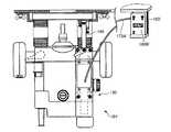
次に、図34に示すように、ルータ1をその上下を逆転させてルータテーブル102に固定して作業を行う場合において、ルータ1のベース110に対する本体130の移動量を利用する切込深さ調整方法について説明する。  Next, as shown in FIG. 34, when working with therouter 1 reversed upside down and fixed to the router table 102, the depth of cut using the amount of movement of themain body 130 relative to thebase 110 of therouter 1 is used. The adjustment method will be described.

先ず、ルータ1をルータテーブル102に取り付ける前に次の作業を行う。即ち、ストッパポール165を本体130に固定しているノブ130Dを緩め、ストッパポール165を移動させてその上端部をベース110上のターンテーブル部115Aの固定手段115Dに固定することによって、ストッパポール165をベース110に固定する。  First, the following work is performed before therouter 1 is attached to the router table 102. That is, theknob 130D that fixes thestopper pole 165 to themain body 130 is loosened, and thestopper pole 165 is moved to fix the upper end of thestopper pole 165 to the fixing means 115D of theturntable portion 115A on thebase 110. Is fixed to thebase 110.

この状態では、本体130がベース110及びストッパポール165に対して相対的に上下に移動し得ることとなり、本体130が移動すると、本体130と一体に移動するラック165Bがピニオン168A及び軸23を回転させる。このため、スリット166aを通抜ける光により発生するパルスを検出部171によって検出することによって、前述と同様に本体130の移動量を演算することができ、求められた本体130の移動量をデジタル表示ユニット160のLCD160C上に表示することができる。このように、本実施の形態では、同一のLCD160C上にストッパポール165の移動量と本体130の移動量との何れをも表示することができる。  In this state, themain body 130 can move up and down relatively with respect to thebase 110 and thestopper pole 165. When themain body 130 moves, therack 165B that moves integrally with themain body 130 rotates thepinion 168A and the shaft 23. Let Therefore, by detecting the pulse generated by the light passing through theslit 166a by thedetection unit 171, the movement amount of themain body 130 can be calculated in the same manner as described above, and the obtained movement amount of themain body 130 is digitally displayed. It can be displayed on theLCD 160C of theunit 160. Thus, in this embodiment, both the movement amount of thestopper pole 165 and the movement amount of themain body 130 can be displayed on thesame LCD 160C.

次に、図34に示すようにルータ1の上下を逆にして、つまりベース110側を本体130に対して鉛直上方として、ベース110に係合するための一対の取付ブラケット103、103を蝶ナット104、104でルータテーブル102の下面に固定することによって、ルータ1をルータテーブル102に取り付ける。そして、切替/TABLEスイッチ160Fを押し、LCD160Cにデジタル表示される本体130の移動量の数値を上下逆転させ、その数値が正面から正しく読み取れるようにする。このとき、デジタル表示ユニット160の表示部160Bの周辺が暗くてLCD160Cにデジタル表示される数値を読み取りづらい場合、またはルータ1を通常状態で使用する場合においても、薄暗い場所等でLCD160Cにデジタル表示される数値が読み取りづらい場合には、ライトスイッチ32を押して表示部160Bを照明してその部分を明るくする。なお、ルータ1をルータテーブル102に取り付けた場合においては、表示部160Bがルータテーブル102の影になって暗くなってしまうので、表示部160Bを照明してその部分を明るくすることは有用である。  Next, as shown in FIG. 34, therouter 1 is turned upside down, that is, the base 110 side is vertically above themain body 130, and the pair of mountingbrackets 103, 103 for engaging with the base 110 are attached to the wing nuts. Therouter 1 is attached to the router table 102 by being fixed to the lower surface of the router table 102 by 104 and 104. Then, the switch /TABLE switch 160F is pressed, and the numerical value of the movement amount of themain body 130 digitally displayed on theLCD 160C is turned upside down so that the numerical value can be read correctly from the front. At this time, even when the periphery of thedisplay unit 160B of thedigital display unit 160 is dark and it is difficult to read the numerical value digitally displayed on theLCD 160C, or when therouter 1 is used in a normal state, it is digitally displayed on theLCD 160C in a dim place. If it is difficult to read the numerical value, the light switch 32 is pressed to illuminate thedisplay unit 160B to brighten that portion. When therouter 1 is attached to the router table 102, thedisplay unit 160B becomes a shadow of the router table 102 and becomes dark. Therefore, it is useful to illuminate thedisplay unit 160B to brighten that portion. .

次に、レバー部材142を回動させることにより係合部材138と雄ネジ部117Bとを係合させ、本体130に対してボルト117が自由に移動できない状態とする。このときの本体130の位置が切込深さ零に対応する位置となり、デジタル表示ユニット160の表示部160Bに設けられた零設定スイッチ160Eを押してLCD160Cにデジタル表示される数値を「0」にリセットする(零点調整)。  Next, thelever member 142 is rotated to engage the engagingmember 138 and themale screw portion 117B so that thebolt 117 cannot move freely with respect to themain body 130. The position of themain body 130 at this time becomes a position corresponding to the cutting depth of zero, and the zerosetting switch 160E provided on thedisplay unit 160B of thedigital display unit 160 is pressed to reset the numerical value digitally displayed on theLCD 160C to “0”. Yes (zero adjustment).

次に、微調整ノブ149を操作してボルト117を回すことにより、ボルト117に螺合する係合部材138が本体130を押上げ本体130を鉛直上方へ移動させる。このときの本体130の移動量は、ルータテーブル102の上面からの刃物151の突出量に一致しており切り込み深さとなり、この移動量は前述のようにデジタル表示ユニット160のLCD160C上に表示される。このため、LCD160Cに表示される数値を見ながらその値が所望の切込深さに一致するまで本体130を上動させ、両者が一致した時点でロックレバー137を締め付けて本体130をその位置に固定すれば、切込深さの調整がなされ、刃物151はルータテーブル102の上面から所定長さ(切込深さ)だけ突出する。  Next, by operating thefine adjustment knob 149 and turning thebolt 117, the engagingmember 138 screwed to thebolt 117 pushes up themain body 130 and moves themain body 130 vertically upward. The amount of movement of themain body 130 at this time corresponds to the amount of protrusion of theblade 151 from the upper surface of the router table 102 and becomes the cutting depth, and this amount of movement is displayed on theLCD 160C of thedigital display unit 160 as described above. The Therefore, while watching the numerical value displayed on theLCD 160C, themain body 130 is moved up until the value matches the desired depth of cut, and when the two match, thelock lever 137 is tightened to bring themain body 130 to that position. If fixed, the cutting depth is adjusted, and theblade 151 protrudes from the upper surface of the router table 102 by a predetermined length (cutting depth).

この際、微調整ノブ149が設けられていない場合には、作業者はハンドル130Eを把持して、コラム111、112外周面上の圧縮バネ136によって本体130を鉛直下方へ押下げる力及び本体130の重力に抗して本体130を鉛直上方へ持上げて、最適な位置へ本体130を移動させる必要があり、これでは本体130の位置の微調整は極めて困難であったが、本実施の形態では、微調整ノブ149を回転させることにより本体130の位置の微調整を極めて容易に行うことができる。  At this time, if thefine adjustment knob 149 is not provided, the operator grasps thehandle 130E, and the force to push themain body 130 vertically downward by thecompression spring 136 on the outer peripheral surfaces of thecolumns 111 and 112 and themain body 130. It is necessary to lift themain body 130 vertically upward against the gravitational force and move themain body 130 to an optimum position. With this, fine adjustment of the position of themain body 130 is extremely difficult. By rotating thefine adjustment knob 149, the position of themain body 130 can be finely adjusted very easily.

上述のようにして切込深さの調整を行った後に、刃物151が被削材Wに接触しない状態で電動機131を駆動させて刃物151を回転させ、この状態で被削材Wをルータテーブル102上で移動させれば、被削材Wが刃物151によって所定の切り込み深さまで加工される。  After adjusting the depth of cut as described above, thecutter 131 is rotated by driving theelectric motor 131 in a state where thecutter 151 does not contact the workpiece W. In this state, the workpiece W is moved to the router table. If the workpiece W is moved on theworkpiece 102, the workpiece W is processed to a predetermined cutting depth by theblade 151.

このような切込深さ調整方法について、上述のようにルータテーブル102にルータ1を固定し本体130に対してベース110を鉛直上方に位置させた状態でルータ1を使用する場合について説明したが、前述のようにルータテーブル102を用いずにルータ1を使用する場合であっても同様に行うことができる。  Such a cutting depth adjustment method has been described in the case where therouter 1 is used with therouter 110 fixed to the router table 102 and the base 110 positioned vertically upward with respect to themain body 130 as described above. Even when therouter 1 is used without using the router table 102 as described above, the same operation can be performed.

以上のように、本実施の形態に係るルータ1によれば、ストッパポール165の本体130に対する移動量と本体130のベース110に対する移動量の双方を切込深さとしてLCD160Cにデジタル表示するようにしたため、そのデジタル表示される移動量を見ながらストッパポール165或は本体130を移動させて切込深さを調整することができ、手持ち作業時及びルータテーブル102を使用した固定作業時の切込深さを正確且つ容易に調整することができる。  As described above, according to therouter 1 according to the present embodiment, both the movement amount of thestopper pole 165 with respect to themain body 130 and the movement amount of themain body 130 with respect to the base 110 are digitally displayed on theLCD 160C as the depth of cut. Therefore, it is possible to adjust the cutting depth by moving thestopper pole 165 or themain body 130 while observing the movement amount displayed on the digital display. The depth can be adjusted accurately and easily.

又、手持ち作業時には、ラック&ピニオン機構によってストッパポール165を本体130に対して移動させることによって、手持ち作業時の切込深さを所定値に正確に調整することができる。  Further, at the time of hand-held work, the depth of cut at the time of hand-held work can be accurately adjusted to a predetermined value by moving thestopper pole 165 with respect to themain body 130 by the rack and pinion mechanism.

更に、ルータテーブル102を使用した固定作業時には、ノブ130Dによってストッパポール165をベース110に固定した状態で、本体130をベース110に対して移動させることによって、切込深さを所定値に調整することができるが、ストッパポール165のベース110に対する固定/解除により、本体130のベース110に対する移動量のデジタル表示とストッパポール165の本体130に対する移動量のデジタル表示の切り替えを容易に行うことができる。  Further, when the router table 102 is fixed, the depth of cut is adjusted to a predetermined value by moving themain body 130 relative to the base 110 while thestopper pole 165 is fixed to thebase 110 by theknob 130D. However, by fixing / releasing thestopper pole 165 with respect to thebase 110, it is possible to easily switch between the digital display of the movement amount of themain body 130 relative to thebase 110 and the digital display of the movement amount of thestopper pole 165 relative to themain body 130. .

又、本実施の形態では、ストッパポール165の本体130に対する移動量と本体130のベース110に対する移動量とを同一のLCD160C上にデジタル表示可能としたため、デジタル表示ユニット160を小型・コンパクト化することができるとともに、手持ち作業時とルータテーブル102を使用した固定作業時のLCD160C上への移動量の表示を同一操作で簡単に行うことができ、切込深さの調整作業が簡略化される。  In the present embodiment, since the movement amount of thestopper pole 165 relative to themain body 130 and the movement amount relative to thebase 110 of themain body 130 can be digitally displayed on thesame LCD 160C, thedigital display unit 160 can be reduced in size and size. In addition, it is possible to easily display the movement amount on theLCD 160C during the hand-held operation and during the fixing operation using the router table 102 by the same operation, and the cutting depth adjustment operation is simplified.

また、本実施の形態では、ストッパポール165の本体130に対する移動量及び本体130のベース110に対する移動量の数値を上下を逆転させてLCD160C上に表示可能としたため、ルータテーブル102を使用した固定作業時にルータ1を上下を逆転させて取り付けた場合であっても、デジタル表示ユニット160のLCD160Cには正しい向きで数値を表示することができ、その数値を正しく容易に読み取ることができる。  In this embodiment, since the numerical values of the amount of movement of thestopper pole 165 relative to themain body 130 and the amount of movement of themain body 130 relative to the base 110 can be displayed upside down on theLCD 160C, fixing work using the router table 102 is performed. Even when therouter 1 is sometimes mounted upside down, the numerical value can be displayed in the correct orientation on theLCD 160C of thedigital display unit 160, and the numerical value can be read correctly and easily.

本発明によるルータは、上述した実施の形態に限定されず、特許請求の範囲に記載した範囲で種々の変形や改良が可能である。例えば、本実施の形態では、係合部材138の係合部材延出部138Bの延出端にはワッシャ140が環装されてネジ141が螺着され、ワッシャ140には駆動部材139の縮径部139Bが当接しており、駆動部材139がボルト117から離間する方向へ移動しようとするときに、ワッシャ140に当接する駆動部材139がワッシャ140及び係合部材138を駆動部材139と一体で移動させることにより、係合部材138が係合解除位置から係合位置に移動させられるように構成されていたが、この構成に限定されない。  The router according to the present invention is not limited to the above-described embodiments, and various modifications and improvements can be made within the scope described in the claims. For example, in the present embodiment, awasher 140 is mounted around the extended end of the engagingmember extending portion 138B of the engagingmember 138 and thescrew 141 is screwed, and the diameter of the drivingmember 139 is reduced on thewasher 140. When theportion 139B is in contact and thedrive member 139 is about to move away from thebolt 117, thedrive member 139 that contacts thewasher 140 moves thewasher 140 and theengagement member 138 together with thedrive member 139. By doing so, theengagement member 138 is configured to be moved from the engagement release position to the engagement position. However, the present invention is not limited to this configuration.

例えば、図35〜図38に示されるように、係合部材138に係合部材延出部138Bを設けず、延出部の延出端に設けられていたワッシャ140やネジを省いた構成としてもよい。この構成では、駆動部材139がノブ部137Aの回動により回転させられて螺進しボルト117に接近する方向へ移動させられることにより、係合部材138が駆動部材139によって図35〜図38の右方向へ移動させられて係合解除位置となる。また、駆動部材139がノブ部137Aの回動により回転させられて螺退しボルト117から離間する方向へ移動させられると、係合部材138は、圧縮バネ145の付勢力によって、図35〜図38の左方向へ移動させられて係合位置となる。  For example, as shown in FIGS. 35 to 38, the engagingmember 138 is not provided with the engagingmember extending portion 138B, and thewasher 140 and the screw provided at the extending end of the extending portion are omitted. Also good. In this configuration, the drivingmember 139 is rotated by the rotation of theknob portion 137A, is screwed, and is moved in a direction approaching thebolt 117, whereby the engagingmember 138 is moved by the drivingmember 139 as shown in FIGS. It is moved to the right and becomes the disengagement position. Further, when the drivingmember 139 is rotated by the rotation of theknob portion 137A and is screwed out and moved away from thebolt 117, the engagingmember 138 is moved by the urging force of thecompression spring 145 as shown in FIGS. 38 is moved to the left to enter the engaged position.

また、図39、図40に示されるように、デジタル表示部ユニット160′を本体130から着脱自在なユニット構成としてもよい。この場合であってもデジタル表示ユニット160′には、本体130に対するストッパポール165の相対的な位置等を表示できるようにするために、デジタル表示ユニット160と本体130とが電気的に接続されている必要がある。このため、デジタル表示ユニット160と本体130とは、図39、図40に示されるようにコード173A′で接続される。  Also, as shown in FIGS. 39 and 40, thedigital display unit 160 ′ may be configured to be detachable from themain body 130. Even in this case, thedigital display unit 160 and themain body 130 are electrically connected to thedigital display unit 160 ′ so that the relative position of thestopper pole 165 with respect to themain body 130 can be displayed. Need to be. Therefore, thedigital display unit 160 and themain body 130 are connected by acord 173A ′ as shown in FIGS.

このように着脱自在とし、本体130からデジタル表示ユニット160′を外した状態でルータ101′を使用する場合には、ルータ101′が本体130に対してベース110を鉛直上方に位置した状態とされた場合であっても、ルータ101′が本体130に対してベース110を鉛直下方に位置した状態とされた場合であっても、デジタル表示ユニット160′の上下は変わらず、本実施の形態のように、デジタル表示ユニット160′の表示部160B′において数値を上下逆転表示可能としなくても、作業者は常に表示された数値を正しい向きで読取ることができる。  When therouter 101 ′ is used with thedigital display unit 160 ′ being detached from themain body 130 as described above, therouter 101 ′ is in a state where thebase 110 is positioned vertically above themain body 130. Even if therouter 101 ′ is in a state where thebase 110 is positioned vertically downward with respect to themain body 130, the top and bottom of thedigital display unit 160 ′ does not change. As described above, the operator can always read the displayed numerical value in the correct direction without making it possible to display the numerical value upside down on thedisplay unit 160B ′ of thedigital display unit 160 ′.

また、この場合、コードによりデジタル表示ユニット160′と本体130とを接続せずに、無線通信によりデジタル表示ユニット160′と本体130との間で数値のデータ等のやり取りを行うようにし、電動機を駆動させるための電源とは別個独立したデジタル表示ユニット専用の電源を設けるようにしてもよい。  In this case, thedigital display unit 160 ′ and themain body 130 are not connected by a cord, and numerical data and the like are exchanged between thedigital display unit 160 ′ and themain body 130 by wireless communication. You may make it provide the power supply for exclusive use of the digital display unit independent of the power supply for driving.

また、本体130の略環状貫通孔130dと対向するダストガイド176の上端部には、図41に示されるように、略環状貫通孔130dの方向へ延出する切粉飛散規制壁176Iが設けられていてもよい。切粉飛散規制壁176Iが設けられていることにより、刃物151による被削材への切込み時に、切粉飛散規制壁176Iよりもダストガイド176の外方へ切粉が飛散することを防止することができる。  Further, as shown in FIG. 41, a chip scattering restriction wall 176I extending in the direction of the substantially annular throughhole 130d is provided at the upper end portion of thedust guide 176 facing the substantially annular throughhole 130d of themain body 130. It may be. By providing the chip scattering restriction wall 176I, it is possible to prevent the chips from scattering outside thedust guide 176 from the chip scattering restriction wall 176I when thecutting tool 151 cuts into the work material. Can do.

また、検出部は本実施の形態の構成に限られない。例えば、遮光板の光センサを用いた光電式、静電容量変化を利用する静電容量方式、ストッパポールに等間隔で着磁された磁極の磁束を検出する磁気方式等の他の任意の検出方法を用いることができる。  Further, the detection unit is not limited to the configuration of the present embodiment. For example, any other detection such as a photoelectric method using a light sensor of a light shielding plate, a capacitance method using a change in capacitance, a magnetic method for detecting magnetic flux of magnetic poles magnetized at equal intervals on a stopper pole, etc. The method can be used.

また、固定手段115Dは、ストッパポール当接位置調節手段115のターンテーブル部115Aの周方向に沿った位置に設けられた構成となっていたが、この構成に限られない。ストッパポールの一端部に当接可能であり、ストッパポールをベースに対して移動不能に固定できればよい。  In addition, the fixingunit 115D is configured to be provided at a position along the circumferential direction of theturntable portion 115A of the stopper pole contactposition adjusting unit 115, but is not limited to this configuration. It is sufficient that the stopper pole can be brought into contact with one end of the stopper pole and the stopper pole can be fixed to the base so as not to move.

また、本体130内には遠心ファン133が設けられていたが、これに限定されず、他の構成のファンが設けられていてもよい。  Moreover, although thecentrifugal fan 133 is provided in themain body 130, it is not limited to this, The fan of another structure may be provided.

また、ダストガイドの略円筒形状部の内周面の径、即ち内径は、略環状貫通孔に対向する略円筒形状部の上端部における位置よりもベース110のダストガイド収容部に当接する略円筒形状部の下端部の位置の方が大きくてもよい。このような構成とすることにより、刃物151による被削材への切込み作業時に略円筒形状部の内周面側において、切粉をファン風によりダストガイドの半径方向外方へ、即ち略円筒形状部の中心寄りの位置から内周面へ接近する方向へと吹飛ばすことができる。  In addition, the diameter of the inner peripheral surface of the substantially cylindrical portion of the dust guide, that is, the inner diameter, is substantially cylindrical that comes into contact with the dust guide housing portion of the base 110 rather than the position at the upper end portion of the substantially cylindrical portion facing the substantially annular through hole. The position of the lower end part of the shape part may be larger. By adopting such a configuration, at the time of the cutting work into the work material by theblade 151, on the inner peripheral surface side of the substantially cylindrical portion, the chips are blown outward in the radial direction of the dust guide by the fan wind, that is, substantially cylindrical. It is possible to blow away from a position closer to the center of the part in a direction approaching the inner peripheral surface.

また、本実施の形態ではストッパポール165、165が設けられていたが、ストッパポールを有しない構成としてもよい。この場合には、本体に対するコラム又ボルトの相対的な位置を検出する等の構成とすればよい。  In this embodiment, thestopper poles 165 and 165 are provided. However, the stopper poles may not be provided. In this case, the configuration may be such as detecting the relative position of the column or bolt with respect to the main body.

また、図10においてライトON/OFFスイッチ160Dと零設定スイッチ160Eの位置を入れ替えて、零設定スイッチ160Eを図10における上方側の位置に配置してもよい。このような配置にすることにより、使用頻度の多い零設定スイッチ160Eがストッパポール165を微調整するノブ168B付近に位置するので、零設定スイッチ160Eを押しやすくなる。  Further, the positions of the light ON /OFF switch 160D and the zerosetting switch 160E in FIG. 10 may be interchanged, and the zerosetting switch 160E may be disposed at the upper position in FIG. With such an arrangement, the frequently used zero settingswitch 160E is positioned near theknob 168B for fine adjustment of thestopper pole 165, so that the zerosetting switch 160E can be easily pushed.

本発明は、ストッパポールを本体に対して移動させ、或は本体をベースに対して移動させることによって刃物の被削材への切込深さを調整する方法を採用する携帯用電気ルータ等の分野において有用である。  The present invention relates to a portable electric router or the like that employs a method of adjusting a cutting depth of a cutting tool into a work material by moving a stopper pole with respect to a main body or moving a main body with respect to a base. Useful in the field.

本発明の実施の形態によるルータを示す部分断面正面図。The fragmentary sectional front view which shows the router by embodiment of this invention.本発明の実施の形態によるルータを示す背面図。The rear view which shows the router by embodiment of this invention.本発明の実施の形態によるルータの導電性ケーシング部を示す要部断面図。The principal part sectional drawing which shows the electroconductive casing part of the router by embodiment of this invention.本発明の実施の形態によるルータのストッパポール位置調整手段を示す要部断面図。The principal part sectional drawing which shows the stopper pole position adjustment means of the router by embodiment of this invention.本発明の実施の形態によるルータを示す断面図。Sectional drawing which shows the router by embodiment of this invention.本発明の実施の形態によるルータの係合部材が係合解除位置にある状態を示す要部断面図。The principal part sectional drawing which shows the state which has the engaging member of the router by embodiment of this invention in a disengagement position.本発明の実施の形態によるルータの係合部材が係合解除位置にある状態を示す要部断面図。The principal part sectional drawing which shows the state which has the engaging member of the router by embodiment of this invention in a disengagement position.本発明の実施の形態によるルータの係合部材が係合位置にある状態を示す要部断面図。The principal part sectional drawing which shows the state which has the engaging member of the router by embodiment of this invention in an engaging position.本発明の実施の形態によるルータの係合部材が係合位置にある状態を示す要部断面図。The principal part sectional drawing which shows the state which has the engaging member of the router by embodiment of this invention in an engaging position.本発明の実施の形態によるルータのデジタル表示ユニットを示す正面図。The front view which shows the digital display unit of the router by embodiment of this invention.本発明の実施の形態によるルータのデジタル表示ユニットを示す分解正面図。The disassembled front view which shows the digital display unit of the router by embodiment of this invention.本発明の実施の形態によるルータのデジタル表示ユニットを示す要部分解正面図。The principal part disassembled front view which shows the digital display unit of the router by embodiment of this invention.本発明の実施の形態によるルータのデジタル表示ユニットを示す要部分解正面図。The principal part disassembled front view which shows the digital display unit of the router by embodiment of this invention.本発明の実施の形態によるルータのデジタル表示ユニットを示す側方断面図。The side sectional view showing the digital display unit of the router by the embodiment of the present invention.本発明の実施の形態によるルータのデジタル表示ユニットのテープを示す拡大図。The enlarged view which shows the tape of the digital display unit of the router by embodiment of this invention.本発明の実施の形態によるルータのデジタル表示ユニットのLCDにインチ法による表示をした状態を示す拡大図。The enlarged view which shows the state displayed on the LCD of the digital display unit of the router by embodiment of this invention by inch method.本発明の実施の形態によるルータのデジタル表示ユニットのLCDにメートル法による表示をした状態を示す拡大図。The enlarged view which shows the state which displayed on the LCD of the digital display unit of the router by embodiment of this invention by the metric system.本発明の実施の形態によるルータの電源回路を示す概念図。The conceptual diagram which shows the power supply circuit of the router by embodiment of this invention.本発明の実施の形態によるルータのベースを示す平面図。The top view which shows the base of the router by embodiment of this invention.本発明の実施の形態によるルータのダストガイドを示す斜視図。The perspective view which shows the dust guide of the router by embodiment of this invention.本発明の実施の形態によるルータのダストガイドを示す斜視図。The perspective view which shows the dust guide of the router by embodiment of this invention.本発明の実施の形態によるルータのダストガイドの第1壁部及び第2壁部を示す要部断面図。The principal part sectional drawing which shows the 1st wall part and 2nd wall part of the dust guide of the router by embodiment of this invention.本発明の実施の形態によるルータのベースを示す断面図。Sectional drawing which shows the base of the router by embodiment of this invention.本発明の実施の形態によるルータのハンドルを示す側方断面図。The side sectional view showing the handle of the router by an embodiment of the invention.本発明の実施の形態によるルータのハンドルが回動した状態を示す側方断面図。The side sectional view showing the state where the handle of the router by an embodiment of the invention rotated.本発明の実施の形態によるルータのハンドルを示す正面方向断面図。The front direction sectional view showing the handle of the router by an embodiment of the invention.本発明の実施の形態によるルータのハンドルと本体突出部との関係を示す分解概念図。The disassembled conceptual diagram which shows the relationship between the handle | steering-wheel of a router and the main-body protrusion part by embodiment of this invention.本発明の実施の形態によるルータのハンドルと本体突出部との接続位置を示す要部断面図。The principal part sectional drawing which shows the connection position of the handle | steering-wheel of a router and main body protrusion part by embodiment of this invention.本発明の実施の形態によるルータのハンドルを作業者が把持している状態を示す概念図。The conceptual diagram which shows the state in which the operator is holding the handle | steering-wheel of the router by embodiment of this invention.本発明の実施の形態によるルータのハンドルを作業者が把持しながら速度可変ダイヤルを操作している状態を示す概念図。The conceptual diagram which shows the state which is operating the speed variable dial, while the operator is holding the handle of the router by embodiment of this invention.本発明の実施の形態によるルータの回路構成を示すブロック図。The block diagram which shows the circuit structure of the router by embodiment of this invention.本発明の実施の形態によるルータにおける信号A、信号Bと切込み深さとの関係を示すグラフ。The graph which shows the relationship between the signal A and the signal B in the router by embodiment of this invention, and the cutting depth.本発明の実施の形態によるルータにおける動作を示すフローチャート。The flowchart which shows the operation | movement in the router by embodiment of this invention.本発明の実施の形態によるルータを、ルータテーブルを用いて使用している状態を示す正面図。The front view which shows the state which is using the router by embodiment of this invention using a router table.本発明の実施の形態の変形例によるルータの係合部材が係合解除位置にある状態を示す要部断面図。The principal part sectional drawing which shows the state which has the engaging member of the router by the modification of embodiment of this invention in a disengagement position.本発明の実施の形態の変形例によるルータの係合部材が係合解除位置にある状態を示す要部断面図。The principal part sectional drawing which shows the state which has the engaging member of the router by the modification of embodiment of this invention in a disengagement position.本発明の実施の形態の変形例によるルータの係合部材が係合位置にある状態を示す要部断面図。The principal part sectional drawing which shows the state which has the engaging member of the router by the modification of embodiment of this invention in an engaging position.本発明の実施の形態の変形例によるルータの係合部材が係合位置にある状態を示す要部断面図。The principal part sectional drawing which shows the state which has the engaging member of the router by the modification of embodiment of this invention in an engaging position.本発明の実施の形態の他の変形例によるルータを示す正面図。The front view which shows the router by the other modification of embodiment of this invention.本発明の実施の形態の他の変形例によるルータを、ルータテーブルを用いて使用している状態を示す正面図。The front view which shows the state which is using the router by the other modification of embodiment of this invention using a router table.本発明の実施の形態の他の変形例によるルータのダストガイドを示す斜視図。The perspective view which shows the dust guide of the router by the other modification of embodiment of this invention.溝加工が施された被削材の部分斜視図。The fragmentary perspective view of the to-be-cut material in which the groove process was given.

符号の説明Explanation of symbols

101、101′・・・ルータ 110・・・ベース 110A・・・摺動面 111、112・・・コラム 117・・・ボルト 117B・・・雄ネジ部 130・・・本体 138・・・係合部材 138A・・外周面 139・・・駆動部材 139C・・・雄ネジ 140・・・ワッシャ 142・・・レバー部材 143・・・無頭ネジ 144・・・回動規制部材 145・・・圧縮バネ 151・・・刃物101, 101 '...router 110 ...base 110A ... slidingsurface 111, 112 ...column 117 ... bolt 117B ...male screw part 130 ...main body 138 ...engagement Member 138A ··Outer surface 139 ···Drive member 139C · · ·Male screw 140 · · ·Washer 142 · · ·lever member 143 · · ·headless screw 144 · · ·rotation regulating member 145 · · ·compression spring 151 ... Cutlery

Claims (7)

Translated fromJapanese
開口部と被削材上を摺動する摺動面とを有するベースと、
該摺動面の反被削材側において該摺動面の該反被削材側に対向して該ベースに垂直の方向に上下動可能に該ベースに支持され、電動機を内蔵し、該摺動面に略垂直の方向であって該ベースへ向かう方向へ該電動機から延出する出力軸を有する本体と、
該出力軸の端部に装着された刃物とを備え、
該開口部は該ベースを貫通して該被削材側と該反被削材側とに開口し、該刃物は、該本体の上下動により該反被削材側から該被削材側へと向かう方向において該ベースへ接近させられて該ベースの該摺動面よりも該被削材側に該開口部から突出可能なルータにおいて、
該摺動面の該反被削材側において該摺動面に略垂直の方向に延出し、一端が該摺動面に垂直の方向へ移動不能且つ回転可能に該ベースに支承され、少なくとも一部に該反被削材側から該被削材側へと向かう方向において該本体を位置調整するための雄ネジ部を有するボルトと、
該ボルトの該雄ネジ部と係合して螺合可能であり該反被削材側から該被削材側へと向かう方向において該本体を位置調整するための雌ネジを有し、該ボルトの該雄ネジ部と該雌ネジとが係合する係合位置と、該雄ネジ部と該雌ネジとの係合が解除される係合解除位置との間で移動可能な係合部材と、
該係合部材を該係合解除位置に保持するための係合解除位置保持手段と、
該係合部材を該係合位置に保持するための弾性部材と、を有し
該本体には本体雌ネジが螺刻され、
該係合解除位置保持手段は該係合部材の移動方向において当接可能な駆動部材を備え、該駆動部材の外周面には該本体雌ネジと螺合する駆動部材雄ネジが設けられ、該駆動部材雄ネジの螺進退により該係合部材を該係合位置又は該係合解除位置とすることを特徴とするルータ。
A base having an opening and a sliding surface sliding on the work material;
The sliding surface is opposed to the anti-work material side of the sliding surface and is supported by the base so as to be movable up and down in a direction perpendicular to the base. A body having an output shaft extending from the motor in a direction substantially perpendicular to the moving surface and toward the base;
A cutter attached to the end of the output shaft,
The opening passes through the base and opens to the work material side and the anti-work material side, and the blade is moved from the anti-work material side to the work material side by the vertical movement of the main body. In a router that can be approached to the base in a direction toward the base and project from the opening to the work material side than the sliding surface of the base,
The sliding surface extends in a direction substantially perpendicular to the sliding surface on the side opposite to the work material, and one end of the sliding surface is supported by the base so as not to move in the direction perpendicular to the sliding surface and to be rotatable. A bolt having a male screw part for adjusting the position of the main body in a direction from the side opposite to the work material to the work material side,
The bolt has a female screw that can be engaged with and screwed with the male screw portion and adjusts the position of the main body in a direction from the anti-work material side to the work material side. An engagement member movable between an engagement position where the male screw portion and the female screw engage with each other, and an engagement release position where the engagement between the male screw portion and the female screw is released. ,
An engagement release position holding means for holding the engagement member in the engagement release position;
An elastic member for holding the engagement member in the engagement position,
The body is threaded with a body female screw,
The disengagement position holding means includes a drive member capable of abutting in the moving direction of the engagement member, and a drive member male screw that is screwed with the main body female screw is provided on an outer peripheral surface of the drive member. A router characterizedin that theengagement member is set to the engagement position or the engagement release position by screwing back and forth of a drive member male screw .
該駆動部材雄ネジと該本体雌ネジとの螺合による該駆動部材の螺進退方向は該ボルトの軸心に垂直の方向に一致し、該係合部材は該駆動部材の螺進退に連動して該係合位置又は該係合解除位置となることを特徴とする請求項1記載のルータ。Screw advancing and retracting direction of the drive member by threaded engagement with the drive member the male thread and thebody female screw coincides with the direction perpendicular to the axis of the bolt, engaging member is linked to the screw advancing and retreating of the driving member The router according toclaim 1 , wherein the router becomes the engagement position or the engagement release position. 該係合部材は、該係合部材の移動方向へ該係合部材の外周面から延出する係合部材延出部を有し、該係合部材延出部の延出端にはフランジ状の当接部材が設けられ、
該駆動部材は、該係合部材延出部の周面上であって該当接部材と該係合部材の外周面との間に配置され、該係合部材延出部の軸を中心として回動可能、且つ該当接部材と該係合部材の外周面とに当接可能であることを特徴とする請求項1記載のルータ。
The engaging member has an engaging member extending portion that extends from the outer peripheral surface of the engaging member in the moving direction of the engaging member, and the extending end of the engaging member extending portion has a flange shape. A contact member is provided,
The drive member is disposed on the peripheral surface of the engaging member extending portion and between the contact member and the outer peripheral surface of the engaging member, and rotates around the axis of the engaging member extending portion. The router according toclaim 1 , wherein the router is movable and is capable of coming into contact with a corresponding contact member and an outer peripheral surface of the engagement member.
該駆動部材は、該駆動部材雄ネジと該本体雌ネジとの螺合により該ボルトの軸心に垂直の方向に螺進退可能であり、該駆動部材が該ボルト側へ螺進することにより該駆動部材は該係合部材に対し当接押圧して該係合部材を該係合解除位置へ移動させ、
該駆動部材を螺退させるときには、該係合部材は該弾性部材の押圧力により該係合位置へと移動させられることを特徴とする請求項1記載のルータ。
The drive member by screwing between the drive member male screw and thebody a female screw may be threadably moved in the direction perpendicular to the axis of the bolt, said by the drive member is screwed into the bolt side The drive member abuts against the engagement member to move the engagement member to the engagement release position,
2. The router according toclaim 1, wherein when the drive member is screwed, the engagement member is moved to the engagement position by a pressing force of the elastic member.
回動操作可能であり、回動操作されることにより該駆動部材が螺進退するように該駆動部材へ回動力を伝達する操作部材と、
該操作部材の回動位置を規制する規制手段とを有し、
該規制手段は該係合部材が該係合位置または該係合解除位置にあるときに該操作部材の回動を規制することを特徴とする請求項2又は請求項4記載のルータ。
An operation member that is pivotable and transmits a rotational force to the drive member so that the drive member is screwed back and forth by being pivoted;
Regulating means for regulating the rotational position of the operating member;
5. The router according toclaim 2 , wherein the restricting means restricts the rotation of the operation member when the engaging member is at the engaging position or the disengaging position.
該操作部材は、該駆動部材の回動軸に垂直の方向に延びる延出部を有するレバー部材であり、
該規制手段は該延出部の回動範囲内の該本体の部分に設けられ、該延出部が回動して該延出部に当接することにより該レバー部材の回動を規制することを特徴とする請求項5記載のルータ。
The operating member is a lever member having an extending portion extending in a direction perpendicular to the rotation axis of the driving member,
The restricting means is provided in a portion of the main body within a rotation range of the extension portion, and the extension portion rotates to restrict rotation of the lever member by contacting the extension portion. The router according toclaim 5 .
該レバー部材と該駆動部材とは互いに連結される連結部を有し該レバー部材と該駆動部材と相対的に回動可能であり、該連結部には、該レバー部材と該駆動部材との相対的な回動を規制し該レバー部材を該駆動部材に対して回動不能に固定可能な固定部材が設けられていることを特徴とする請求項6記載のルータ。The lever member and the drive member have a connecting portion connected to each other, and are rotatable relative to the lever member and the driving member. The connecting portion includes a connection between the lever member and the driving member. The router according toclaim 6, further comprising a fixing member that restricts relative rotation and is capable of fixing the lever member to the driving member so as not to rotate.
JP2005151350A2005-05-242005-05-24 RouterExpired - Fee RelatedJP4843254B2 (en)

Priority Applications (7)

Application NumberPriority DateFiling DateTitle
JP2005151350AJP4843254B2 (en)2005-05-242005-05-24 Router
US11/438,369US7367760B2 (en)2005-05-242006-05-23Power tool
AT06252691TATE417713T1 (en)2005-05-242006-05-24 POWER TOOL
CN200610142276.9ACN1911594B (en)2005-05-242006-05-24 electrical tools
DE602006004249TDE602006004249D1 (en)2005-05-242006-05-24 power tool
EP06252691AEP1726415B1 (en)2005-05-242006-05-24Power tool
US12/115,165US7726918B2 (en)2005-05-242008-05-05Power tool

Applications Claiming Priority (1)

Application NumberPriority DateFiling DateTitle
JP2005151350AJP4843254B2 (en)2005-05-242005-05-24 Router

Publications (3)

Publication NumberPublication Date
JP2006326931A JP2006326931A (en)2006-12-07
JP2006326931A5 JP2006326931A5 (en)2008-07-03
JP4843254B2true JP4843254B2 (en)2011-12-21

Family

ID=36809647

Family Applications (1)

Application NumberTitlePriority DateFiling Date
JP2005151350AExpired - Fee RelatedJP4843254B2 (en)2005-05-242005-05-24 Router

Country Status (6)

CountryLink
US (2)US7367760B2 (en)
EP (1)EP1726415B1 (en)
JP (1)JP4843254B2 (en)
CN (1)CN1911594B (en)
AT (1)ATE417713T1 (en)
DE (1)DE602006004249D1 (en)

Families Citing this family (28)

* Cited by examiner, † Cited by third party
Publication numberPriority datePublication dateAssigneeTitle
USD546654S1 (en)*2004-01-292007-07-17Black & Decker Inc.Router with plunge base
JP4843254B2 (en)*2005-05-242011-12-21日立工機株式会社 Router
CN100563955C (en)*2005-11-092009-12-02苏州宝时得电动工具有限公司Bakelite mills
CN101007410B (en)*2006-01-262010-05-12苏州宝时得电动工具有限公司Electric wood milling machine
US20100018609A1 (en)*2006-04-262010-01-28Demain Technology Pty Ltd.Power Tool
DE102006061239A1 (en)*2006-12-222008-06-26Robert Bosch Gmbh router
US8967923B2 (en)2012-01-132015-03-03Aeg Electric Tools GmbhDust suction device for drilling machine
US9776296B2 (en)2008-05-092017-10-03Milwaukee Electric Tool CorporationPower tool dust collector
US8607833B2 (en)*2009-02-132013-12-17Robert Bosch GmbhRouter depth adjustment mechanism
JP2011073159A (en)*2009-09-292011-04-14Makita CorpPower tools
US8875804B2 (en)2010-01-072014-11-04Black & Decker Inc.Screwdriving tool having a driving tool with a removable contact trip assembly
CN102152342B (en)*2011-03-022013-12-18浙江亚特电器有限公司Chain saw speed regulating structure
WO2012159123A2 (en)*2011-05-192012-11-22Alec RiversAutomatically guided tools
US20120318113A1 (en)*2011-06-202012-12-20Dan CobleOptical Aid for Power Tools
JP5575713B2 (en)*2011-08-192014-08-20オトロデザイン株式会社 Device for adjusting the amount of protrusion of a blade in a cutting machine
CN103128862A (en)*2011-12-032013-06-05苏州豪特景精密机械有限公司Floating cutting device
EP3964902B1 (en)2012-04-262024-01-03Shaper Tools, Inc.Systems and methods for performing a task on a material, or locating the position of a device relative to the surface of the material
US20140251649A1 (en)*2013-03-112014-09-11Makita CorporationPower tool assembly, power tool, and auxiliary handle member
US9403221B2 (en)*2013-03-142016-08-02Robert Bosch GmbhOne handed plunge base for a router
WO2016089834A1 (en)*2014-12-012016-06-09Robert Bosch GmbhDual adjustable depth rod for router
WO2016183390A1 (en)2015-05-132016-11-17Taktia LlcSystems, methods and apparatus for guided tools
ITUB20169905A1 (en)*2016-01-112017-07-11Hartwig Kamelger Mortising machine for making joints
GB201600883D0 (en)*2016-01-182016-03-02Power Box AgImprovements to router apparatus
GB201600885D0 (en)*2016-01-182016-03-02Power Box AgImprovements to router apparatus
RU2748005C2 (en)2016-08-192021-05-18Шапер Тулс, Инк.Systems, methods and device for sharing tool manufacturing and design data
DE102017205565B4 (en)2017-03-312024-12-19Robert Bosch Gmbh hand tool machine
CN212042789U (en)2019-05-152020-12-01米沃奇电动工具公司 router
EP4052874A4 (en)*2019-10-312023-01-04Koki Holdings Co., Ltd. WOOD ROUTER

Family Cites Families (56)

* Cited by examiner, † Cited by third party
Publication numberPriority datePublication dateAssigneeTitle
US2664768A (en)1950-06-011954-01-05Aloysius R ClyneMotion limiting device
US4272821A (en)*1979-09-181981-06-09Black & Decker Inc.Digital blade adjustment read-out for a portable power tool
JPS5835441Y2 (en)*1979-09-181983-08-10日立工機株式会社 Electric router cutting depth adjustment mechanism
JPS5648604A (en)1979-09-281981-05-01Canon IncProduction of color filter
US4281694A (en)*1979-11-051981-08-04Gorman Thomas ECutting guide for a router or similar tool
JPS56123205U (en)*1980-02-181981-09-19
JPS56123205A (en)1980-02-221981-09-28Dainippon Printing Co LtdPacking method by baggin box
US4316685A (en)*1980-02-291982-02-23Black & Decker Inc.Plunge type router
US4317176A (en)*1980-03-241982-02-23Black & Decker Inc.Microcomputer controlled power tool
US4652191A (en)*1986-02-041987-03-24Lucien BernierPress router
US4770573A (en)*1986-10-151988-09-13Ryobi Ltd.Cutting depth adjusting mechanism of a router
JPH0611126Y2 (en)*1987-08-071994-03-23リョービ株式会社 Adjusting mechanism in router
US4836720A (en)*1988-06-221989-06-06Hadden Terrence BDrill guide
DE3824200C1 (en)*1988-07-161993-08-26Robert Bosch Gmbh, 7000 Stuttgart, De
US4982509A (en)*1988-08-191991-01-08Delta International Machinery Corp.Measurement system having multiple display orientations
US4938642A (en)*1988-09-021990-07-03Hitachi Koki Company, LimitedPortable electric router
JPH0620726B2 (en)1988-09-021994-03-23日立工機株式会社 Cutting depth adjustment method for portable electric router
DE3834418A1 (en)1988-10-101990-04-12Leitz Wild Gmbh SCREW GEAR
DE4008224A1 (en)*1990-03-151991-09-19Metabowerke Kg MILLING DEEP FINE ADJUSTING DEVICE OF A MILL
DE9007585U1 (en)1990-04-091993-02-18Hummel, Herbert, 7410 Reutlingen Snap-in threaded nut
DE4127730A1 (en)1991-08-221993-03-04Ford Werke Ag SHIFT LEVER BEARING FOR TRANSMISSION OF MOTOR VEHICLES
US5143494A (en)*1991-10-181992-09-01Ryobi Motor Products Corp.Depth of cut lock mechanism for a plunge type router
US5191921A (en)*1991-10-181993-03-09Ryobi Motor Products Corp.Adjustable depth of cut stop mechanism for a plunge type router
US5139061A (en)*1991-10-281992-08-18Neilson Patrick JRouter base table insert
DE9114811U1 (en)*1991-11-281993-04-01Robert Bosch Gmbh, 7000 Stuttgart Milling machine
US5207253A (en)*1992-03-201993-05-04Ryobi Motor Products, CorpPlunge router
JPH0620726A (en)1992-06-301994-01-28Meidensha CorpMeasuring method for charging depth of zinc-bromine battery
US5685676A (en)*1992-09-151997-11-11Johnson; Joe C.Router carriage attachment
US5353852A (en)*1993-09-161994-10-11Ryobi Motor Products CorporationDepth of cut locking mechanism for a plunge-type router
GB9404003D0 (en)*1994-03-021994-04-20Black & Decker IncPlunge type router
CA2143128E (en)*1994-03-032005-06-21Stefan BlickhanRouter
DE4426717A1 (en)*1994-07-211996-01-25Black & Decker Inc Device, in particular router for machining a workpiece
US5590989A (en)*1996-02-151997-01-07Mulvihill; RalphFlexible router height-adjustment mechanism
US5725036A (en)*1996-05-231998-03-10Walter; Daniel L.Plunge router with precision adjustment mechanism and conversion kit
US5853274A (en)*1997-11-041998-12-29S-B Power Tool CompanyVertical adjustment mechanism for fixed-base router
US6319233B1 (en)1998-04-172001-11-20Becton, Dickinson And CompanySafety shield system for prefilled syringes
US5918652A (en)*1998-08-281999-07-06Lee Valley Tools Ltd.Router bit positioning mechanism
US6261036B1 (en)*1998-11-162001-07-17Porter-Cable CorporationPlunge router locking system
US6079915A (en)*1998-11-162000-06-27Porter-Cable CorporationPlunge router depth stop system
US6113323A (en)*1998-11-162000-09-05Porter-Cable CorporationPlunge router sub-base alignment
US6139229A (en)*1998-11-162000-10-31Porter-Cable CorporationPlunge router fine depth adjustment system
US6065912A (en)*1998-11-162000-05-23Porter-Cable CorporationRouter switching system
US5998897A (en)*1998-11-161999-12-07Porter-Cable CorporationRouter chuck mounting system
US5988241A (en)*1998-11-161999-11-23Porter-Cable CorporationErgonomic router handles
US6318936B1 (en)*2000-06-132001-11-20Mcfarlin, Jr. Robert E.Plunge router adjustment mechanism and method
DE10029134A1 (en)*2000-06-142001-12-20Hilti Ag Depth stop for hand tools
DE60143412D1 (en)*2000-08-112010-12-16Milwaukee Electric Tool Corp router
US6474378B1 (en)*2001-05-072002-11-05S-B Power Tool CompanyPlunge router having electronic depth adjustment
US6863480B1 (en)*2002-08-062005-03-08Porter-Cable CorporationRouter plunge depth adjustment mechanism
US6896451B2 (en)*2003-10-142005-05-24Credo Technology CorporationDepth rod adjustment mechanism for a plunge-type router
US20060045643A1 (en)*2004-08-252006-03-02Phillip A. AdamsLevel-adjustable tool support
CN2753547Y (en)*2004-11-152006-01-25苏州宝时得电动工具有限公司Electric woodmilling machine
JP4843254B2 (en)*2005-05-242011-12-21日立工機株式会社 Router
CN100563955C (en)*2005-11-092009-12-02苏州宝时得电动工具有限公司Bakelite mills
CN101007410B (en)*2006-01-262010-05-12苏州宝时得电动工具有限公司Electric wood milling machine
JP2007203675A (en)*2006-02-032007-08-16Hitachi Koki Co Ltd Router

Also Published As

Publication numberPublication date
US7726918B2 (en)2010-06-01
US20080206008A1 (en)2008-08-28
US20060269377A1 (en)2006-11-30
EP1726415B1 (en)2008-12-17
ATE417713T1 (en)2009-01-15
US7367760B2 (en)2008-05-06
EP1726415A1 (en)2006-11-29
JP2006326931A (en)2006-12-07
DE602006004249D1 (en)2009-01-29
CN1911594A (en)2007-02-14
CN1911594B (en)2011-10-05

Similar Documents

PublicationPublication DateTitle
JP4843254B2 (en) Router
US8770076B2 (en)Cutter with laser generator that irradiates cutting position on workpiece to facilitate alignment of blade with cutting position
CN103537754B (en) portable cutting machine
US20180169885A1 (en)Portable cutting devices
JP4984313B2 (en) Tabletop cutting machine
JPH1134001A (en)Circular sawing machine
US10668644B2 (en)Portable cutting devices
US20040060178A1 (en)Circular saw
CN100462172C (en) Miter saw with angle adjustment mechanism
US7523691B2 (en)Miter saw having digital display capable of displaying specific angle
JP6878168B2 (en) Portable processing machine
JP2006130902A (en) Router
JP4599909B2 (en) Tabletop circular saw
JP2006326932A (en) Router
JP2006326933A (en) Router
US6260460B1 (en)Machining tools having adjustable fences
JP4656377B2 (en) Tabletop cutting machine
JP2021164982A (en)Portable cutting machine
JP5989453B2 (en) Electric rotary tool
JP2022090789A (en) Desktop cutting machine
CN118513604A (en) Electric cutting machine with quick-change guard set
TW202432305A (en)Electric cutting machine with quick-change guard assembly capable of automatically switching the rotation direction of the cutting tool when the quick-change guard assembly is installed, without the need of using additional switches to change the cutting tool direction
JP2006035608A (en) Tabletop cutting machine
JP2006035458A (en) Tabletop cutting machine
JPS63143094A (en) portable electric cutting tool

Legal Events

DateCodeTitleDescription
A521Request for written amendment filed

Free format text:JAPANESE INTERMEDIATE CODE: A523

Effective date:20080515

A621Written request for application examination

Free format text:JAPANESE INTERMEDIATE CODE: A621

Effective date:20080515

A977Report on retrieval

Free format text:JAPANESE INTERMEDIATE CODE: A971007

Effective date:20091222

A131Notification of reasons for refusal

Free format text:JAPANESE INTERMEDIATE CODE: A131

Effective date:20100105

A521Request for written amendment filed

Free format text:JAPANESE INTERMEDIATE CODE: A523

Effective date:20100303

A02Decision of refusal

Free format text:JAPANESE INTERMEDIATE CODE: A02

Effective date:20100817

A521Request for written amendment filed

Free format text:JAPANESE INTERMEDIATE CODE: A523

Effective date:20101117

A911Transfer to examiner for re-examination before appeal (zenchi)

Free format text:JAPANESE INTERMEDIATE CODE: A911

Effective date:20101130

A912Re-examination (zenchi) completed and case transferred to appeal board

Free format text:JAPANESE INTERMEDIATE CODE: A912

Effective date:20110204

A521Request for written amendment filed

Free format text:JAPANESE INTERMEDIATE CODE: A523

Effective date:20110905

A01Written decision to grant a patent or to grant a registration (utility model)

Free format text:JAPANESE INTERMEDIATE CODE: A01

A61First payment of annual fees (during grant procedure)

Free format text:JAPANESE INTERMEDIATE CODE: A61

Effective date:20111007

R150Certificate of patent or registration of utility model

Ref document number:4843254

Country of ref document:JP

Free format text:JAPANESE INTERMEDIATE CODE: R150

Free format text:JAPANESE INTERMEDIATE CODE: R150

FPAYRenewal fee payment (event date is renewal date of database)

Free format text:PAYMENT UNTIL: 20141014

Year of fee payment:3

S533Written request for registration of change of name

Free format text:JAPANESE INTERMEDIATE CODE: R313533

R350Written notification of registration of transfer

Free format text:JAPANESE INTERMEDIATE CODE: R350

LAPSCancellation because of no payment of annual fees

[8]ページ先頭

©2009-2025 Movatter.jp