Movatterモバイル変換


[0]ホーム

URL:


JP4842040B2 - Electronics - Google Patents

Electronics
Download PDF

Info

Publication number
JP4842040B2
JP4842040B2JP2006202284AJP2006202284AJP4842040B2JP 4842040 B2JP4842040 B2JP 4842040B2JP 2006202284 AJP2006202284 AJP 2006202284AJP 2006202284 AJP2006202284 AJP 2006202284AJP 4842040 B2JP4842040 B2JP 4842040B2
Authority
JP
Japan
Prior art keywords
heat
main body
refrigerant
circuit board
printed circuit
Prior art date
Legal status (The legal status is an assumption and is not a legal conclusion. Google has not performed a legal analysis and makes no representation as to the accuracy of the status listed.)
Expired - Fee Related
Application number
JP2006202284A
Other languages
Japanese (ja)
Other versions
JP2008028332A (en
Inventor
真純 鈴木
亨匡 青木
洋介 角田
益生 大西
正彦 服部
Current Assignee (The listed assignees may be inaccurate. Google has not performed a legal analysis and makes no representation or warranty as to the accuracy of the list.)
Fujitsu Ltd
Original Assignee
Fujitsu Ltd
Priority date (The priority date is an assumption and is not a legal conclusion. Google has not performed a legal analysis and makes no representation as to the accuracy of the date listed.)
Filing date
Publication date
Application filed by Fujitsu LtdfiledCriticalFujitsu Ltd
Priority to JP2006202284ApriorityCriticalpatent/JP4842040B2/en
Priority to TW096126926Aprioritypatent/TWI340316B/en
Priority to EP07113060Aprioritypatent/EP1884866A1/en
Priority to KR1020070074561Aprioritypatent/KR100916569B1/en
Priority to CN2007101390902Aprioritypatent/CN101115376B/en
Priority to US11/878,616prioritypatent/US7672125B2/en
Publication of JP2008028332ApublicationCriticalpatent/JP2008028332A/en
Application grantedgrantedCritical
Publication of JP4842040B2publicationCriticalpatent/JP4842040B2/en
Expired - Fee Relatedlegal-statusCriticalCurrent
Anticipated expirationlegal-statusCritical

Links

Images

Classifications

Landscapes

Description

Translated fromJapanese

本発明は、例えばノートブックパーソナルコンピュータといった電子機器に関する。  The present invention relates to an electronic device such as a notebook personal computer.

電子機器にはプリント基板が組み込まれる。プリント基板上にはLSIチップといった電子部品が実装される。電子部品の冷却にあたって、プリント基板上には液冷ユニットが配置される。電子部品上には液冷ジャケットといった受熱器が受け止められる。受熱器から冷媒の循環経路は一巡する。循環経路にはポンプやタンクが組み入れられる。ポンプやタンクはプリント基板上に配置される。
特開2005−19760号公報特開2005−317798号公報
A printed circuit board is incorporated in the electronic device. Electronic components such as LSI chips are mounted on the printed circuit board. A liquid cooling unit is disposed on the printed circuit board for cooling the electronic components. A heat receiver such as a liquid cooling jacket is received on the electronic component. The circulation path of the refrigerant from the heat receiver makes a round. Pumps and tanks are incorporated in the circulation path. Pumps and tanks are arranged on the printed circuit board.
Japanese Patent Laid-Open No. 2005-19760 JP 2005-317798 A

電子部品の処理動作中、電子部品は発熱する。電子部品の熱は受熱器やプリント基板に受け渡される。プリント基板の温度は上昇する。ポンプやタンクはプリント基板上に配置されることから、プリント基板の温度上昇に基づきポンプ内やタンク内で冷媒の温度は上昇してしまう。電子部品から冷媒に熱は十分に受け渡されることができない。  During the processing operation of the electronic component, the electronic component generates heat. The heat of the electronic component is transferred to the heat receiver or the printed circuit board. The temperature of the printed circuit board increases. Since the pump and the tank are arranged on the printed circuit board, the temperature of the refrigerant increases in the pump and the tank based on the temperature increase of the printed circuit board. Heat cannot be sufficiently transferred from the electronic component to the refrigerant.

本発明は、上記実状に鑑みてなされたもので、放熱の効率を高めることができる電子機器を提供することを目的とする。  This invention is made | formed in view of the said actual condition, and it aims at providing the electronic device which can raise the efficiency of heat dissipation.

上記目的を達成するために、第1発明によれば、プリント基板と、プリント基板に実装される電子部品と、伝熱板で電子部品に受け止められて、伝熱板上に冷媒の流通路を区画する受熱器と、受熱器から一巡する循環経路と、循環経路に組み入れられて、冷媒から熱を奪う熱交換器と、プリント基板の外側に配置されつつ循環経路に組み入れられて、循環経路内の空気を貯蔵するタンクとを備えることを特徴とする電子機器が提供される。  To achieve the above object, according to the first invention, a printed circuit board, an electronic component mounted on the printed circuit board, and a heat transfer plate are received by the electronic component, and a refrigerant flow path is provided on the heat transfer plate. A heat receiver that divides, a circulation path that makes a round from the heat receiver, a heat exchanger that is incorporated in the circulation path and takes heat away from the refrigerant, and is incorporated in the circulation path while being disposed outside the printed circuit board, There is provided an electronic device comprising a tank for storing the air.

こうした電子機器では、電子部品は発熱する。電子部品の熱は受熱器の伝熱板に受け渡される。熱は伝熱板から冷媒に受け渡される。冷媒の温度は上昇する。熱交換器は冷媒の熱を奪う。こうして冷媒は冷却される。その一方で、電子部品の熱はプリント基板に受け渡される。プリント基板内の配線パターンを介して熱はプリント基板内に広がる。タンクはプリント基板の外側に配置されることから、プリント基板内の熱はタンクに伝達されない。タンク内の冷媒の温度上昇は回避される。放熱の効率は高められることができる。  In such an electronic device, the electronic component generates heat. The heat of the electronic component is transferred to the heat transfer plate of the heat receiver. Heat is transferred from the heat transfer plate to the refrigerant. The temperature of the refrigerant rises. The heat exchanger takes away the heat of the refrigerant. Thus, the refrigerant is cooled. On the other hand, the heat of the electronic component is transferred to the printed circuit board. Heat spreads in the printed circuit board through the wiring pattern in the printed circuit board. Since the tank is disposed outside the printed circuit board, heat in the printed circuit board is not transferred to the tank. An increase in the temperature of the refrigerant in the tank is avoided. The efficiency of heat dissipation can be increased.

以上のような電子機器は、プリント基板の外側に配置されつつ循環経路に組み入れられて、循環経路で冷媒を循環させるポンプをさらに備えてもよい。こうしてポンプがプリント基板の外側に配置されれば、プリント基板内の熱はポンプに伝達されない。ポンプ内の冷媒の温度上昇は回避される。放熱の効率は一層高められることができる。その一方で、タンクおよびプリント基板の間には仕切り板が配置されてもよい。こうした仕切り板の働きでタンクに向かって電子部品の熱を帯びた空気の流通は回避される。タンク内の冷媒の温度上昇は回避される。  The electronic apparatus as described above may further include a pump that is incorporated in the circulation path while being arranged outside the printed circuit board and circulates the refrigerant in the circulation path. Thus, if the pump is arranged outside the printed circuit board, heat in the printed circuit board is not transferred to the pump. An increase in the temperature of the refrigerant in the pump is avoided. The efficiency of heat dissipation can be further increased. On the other hand, a partition plate may be disposed between the tank and the printed board. By such a function of the partition plate, circulation of air heated by electronic components toward the tank is avoided. An increase in the temperature of the refrigerant in the tank is avoided.

第2発明によれば、プリント基板と、プリント基板に実装される電子部品と、伝熱板で電子部品に受け止められて、伝熱板上に冷媒の流通路を区画する受熱器と、受熱器から一巡する循環経路と、循環経路に組み入れられて、冷媒から熱を奪う熱交換器と、プリント基板の外側に配置されつつ循環経路に組み入れられて、循環経路で冷媒を循環させるポンプとを備えることを特徴とする電子機器が提供される。前述と同様に、プリント基板内の熱はポンプに伝達されない。ポンプ内で冷媒の温度上昇は回避される。放熱の効率は高められることができる。その他、ポンプおよびプリント基板の間には仕切り板が配置されてもよい。  According to the second invention, a printed circuit board, an electronic component mounted on the printed circuit board, a heat receiver that is received by the electronic component by the heat transfer plate, and defines a refrigerant flow path on the heat transfer plate, and a heat receiver A circulation path that circulates from the inside, a heat exchanger that is incorporated in the circulation path to take heat away from the refrigerant, and a pump that is disposed outside the printed circuit board and is incorporated in the circulation path to circulate the refrigerant in the circulation path. An electronic apparatus characterized by the above is provided. As before, heat in the printed circuit board is not transferred to the pump. An increase in the temperature of the refrigerant in the pump is avoided. The efficiency of heat dissipation can be increased. In addition, a partition plate may be disposed between the pump and the printed board.

以上のように本発明によれば、放熱の効率を高めることができる電子機器が提供されることができる。  As described above, according to the present invention, it is possible to provide an electronic device that can increase the efficiency of heat dissipation.

以下、添付図面を参照しつつ本発明の一実施形態を説明する。  Hereinafter, an embodiment of the present invention will be described with reference to the accompanying drawings.

図1は本発明の第1実施形態に係る電子機器の一具体例すなわちノートブックパーソナルコンピュータ(ノートパソコン)11の外観を概略的に示す。このノートパソコン11は、薄型の第1筐体すなわち本体筐体12と、この本体筐体12に揺動自在に連結される第2筐体すなわちディスプレイ用筐体13とを備える。本体筐体12は、ベース12aと、ベース12aに着脱自在に結合されるカバー12bとを備える。本体筐体12の表面にはキーボード14やポインティングデバイス15といった入力装置が組み込まれる。利用者はこういった入力装置14、15から指示やデータを入力することができる。  FIG. 1 schematically shows an appearance of a specific example of an electronic apparatus according to the first embodiment of the present invention, that is, a notebook personal computer (notebook personal computer) 11. Thenotebook computer 11 includes a thin first housing, that is, amain body housing 12, and a second housing, that is, adisplay housing 13 that is swingably connected to themain body housing 12. Themain body housing 12 includes abase 12a and acover 12b that is detachably coupled to thebase 12a. Input devices such as akeyboard 14 and apointing device 15 are incorporated on the surface of themain housing 12. The user can input instructions and data from theseinput devices 14 and 15.

ディスプレイ用筐体13には例えばLCD(液晶ディスプレイ)パネルモジュール16が組み込まれる。LCDパネルモジュール16の画面は、ディスプレイ用筐体13に区画される窓孔17に臨む。画面にはテキストやグラフィックスが表示されることができる。利用者はそういったテキストやグラフィックスに基づきノートパソコン11の動作を確認することができる。ディスプレイ用筐体13は、本体筐体12に対する揺動を通じて本体筐体12に重ね合わせられることができる。  For example, an LCD (liquid crystal display)panel module 16 is incorporated in thedisplay housing 13. The screen of theLCD panel module 16 faces thewindow hole 17 defined in thedisplay housing 13. Text and graphics can be displayed on the screen. The user can confirm the operation of thenotebook computer 11 based on such text and graphics. Thedisplay housing 13 can be overlaid on the main body housing 12 through swinging with respect to themain body housing 12.

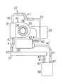
図2に示されるように、本体筐体12の収容空間にはプリント基板ユニット18が収容される。プリント基板ユニット18は、プリント基板19と、プリント基板19の表面に実装される電子部品すなわち第1および第2LSI(大規模集積回路)パッケージ21、22とを備える。第1LSIパッケージ21では、小型のプリント基板上に例えばCPU(中央演算処理装置)チップ(図示されず)が実装される。第2LSIパッケージ22では、小型のプリント基板上に例えばビデオチップ(図示されず)が実装される。CPUチップは例えばOS(オペレーティングシステム)やアプリケーションソフトウェアに基づき演算処理を実施する。ビデオチップは例えばCPUチップの演算処理に基づき画像処理を実行する。  As shown in FIG. 2, the printedcircuit board unit 18 is accommodated in the accommodating space of themain housing 12. The printedcircuit board unit 18 includes a printedcircuit board 19 and electronic components mounted on the surface of theprinted circuit board 19, that is, first and second LSI (large scale integrated circuit)packages 21 and 22. In thefirst LSI package 21, for example, a CPU (Central Processing Unit) chip (not shown) is mounted on a small printed circuit board. In thesecond LSI package 22, for example, a video chip (not shown) is mounted on a small printed circuit board. The CPU chip performs arithmetic processing based on, for example, an OS (operating system) or application software. For example, the video chip performs image processing based on arithmetic processing of the CPU chip.

プリント基板19の外側には、本体筐体12の収容空間にDVD駆動装置23やハードディスク駆動装置(HDD)24といった記録媒体駆動装置が収容される。前述のOSやアプリケーションソフトウェアは例えばHDD24に格納されればよい。本体筐体12の収容空間にはカードユニット25が収容される。カードユニット25には、カードスロットからメモリカードやSCSIカード、LANカードといったPCカードが差し込まれる。カードユニット25は例えばプリント基板19に実装されればよい。  A recording medium drive device such as aDVD drive device 23 or a hard disk drive device (HDD) 24 is housed in the housing space of themain body housing 12 outside the printedcircuit board 19. The OS and application software described above may be stored in theHDD 24, for example. Thecard unit 25 is accommodated in the accommodating space of themain body housing 12. A PC card such as a memory card, a SCSI card, or a LAN card is inserted into thecard unit 25 from a card slot. Thecard unit 25 may be mounted on the printedcircuit board 19, for example.

本体筐体12の収容空間にはプリント基板19上に液冷ユニット27が配置される。液冷ユニット27は、第1LSIパッケージ21に受け止められる第1受熱器28を備える。第1受熱器28はCPUチップの熱を奪う。第1受熱器28は例えばプリント基板19にねじ留めされればよい。液冷ユニット27では、第1受熱器28から一巡する冷媒の循環経路が確立される。ここでは、冷媒には例えばプロピレングリコール系の不凍液が用いられればよい。第1受熱器28の詳細は後述される。  Aliquid cooling unit 27 is disposed on the printedcircuit board 19 in the housing space of themain body housing 12. Theliquid cooling unit 27 includes afirst heat receiver 28 received by thefirst LSI package 21. Thefirst heat receiver 28 takes the heat of the CPU chip. Thefirst heat receiver 28 may be screwed to the printedcircuit board 19, for example. In theliquid cooling unit 27, a refrigerant circulation path that makes a round from thefirst heat receiver 28 is established. Here, for example, a propylene glycol antifreeze may be used as the refrigerant. Details of thefirst heat receiver 28 will be described later.

循環経路には第2LSIパッケージ22に受け止められる第2受熱器29が組み入れられる。第2受熱器29は第1受熱器28の下流で第1受熱器28に接続される。第2受熱器29は、ビデオチップに受け止められる伝熱板を備える。こうして第2受熱器29はビデオチップの熱を奪う。伝熱板は後述の金属管に取り付けられる。伝熱板は例えばプリント基板19にねじ留めされればよい。伝熱板は例えばアルミニウムといった熱伝導性の金属材料から形成されればよい。  Asecond heat receiver 29 that is received by thesecond LSI package 22 is incorporated in the circulation path. Thesecond heat receiver 29 is connected to thefirst heat receiver 28 downstream of thefirst heat receiver 28. Thesecond heat receiver 29 includes a heat transfer plate received by the video chip. Thus, thesecond heat receiver 29 takes the heat of the video chip. The heat transfer plate is attached to a metal tube described later. The heat transfer plate may be screwed to the printedcircuit board 19, for example. The heat transfer plate may be made of a heat conductive metal material such as aluminum.

循環経路には冷媒から熱を奪う熱交換器31が組み入れられる。熱交換器31は第2受熱器29の下流で第2受熱器29に接続される。熱交換器31にはファンユニット32の送風口が向き合わせられる。熱交換器31やファンユニット32は例えばプリント基板19にねじ留めされればよい。熱交換器31は、ファンユニット32と本体筐体12の排気口33との間に配置される。ファンユニット32は、熱交換器31から排気口33に抜ける気流を生成する。熱交換器31およびファンユニット32の詳細は後述される。ファンユニット32は、プリント基板19に形成される切り欠き内に配置されればよい。  Aheat exchanger 31 that takes heat away from the refrigerant is incorporated in the circulation path. Theheat exchanger 31 is connected to thesecond heat receiver 29 downstream of thesecond heat receiver 29. The air outlet of thefan unit 32 faces theheat exchanger 31. Theheat exchanger 31 and thefan unit 32 may be screwed to the printedcircuit board 19, for example. Theheat exchanger 31 is disposed between thefan unit 32 and theexhaust port 33 of themain body housing 12. Thefan unit 32 generates an airflow that flows from theheat exchanger 31 to theexhaust port 33. Details of theheat exchanger 31 and thefan unit 32 will be described later. Thefan unit 32 may be disposed in a notch formed in the printedcircuit board 19.

ファンユニット32はファンハウジング34を備える。ファンハウジング34は所定の収容空間を区画する。ファンハウジング34の底板および天板には吸気用開口35が形成される。吸気用開口35はファンハウジング34の内側の収容空間とファンハウジング34の外側の空間とを相互に接続する。ファンハウジング34の収容空間にはファン36が収容される。  Thefan unit 32 includes afan housing 34. Thefan housing 34 defines a predetermined accommodation space. Anintake opening 35 is formed in the bottom plate and the top plate of thefan housing 34. Theintake opening 35 connects the accommodation space inside thefan housing 34 and the space outside thefan housing 34 to each other. Afan 36 is housed in the housing space of thefan housing 34.

循環経路にはタンク37が組み入れられる。タンク37は熱交換器31の下流で熱交換器31に接続される。タンク37は例えばアルミニウムといった熱伝導性の金属材料から形成されればよい。タンク37は例えばプリント基板19にねじ留めされればよい。タンク37は循環経路内で冷媒や空気を貯蔵することができる。冷媒や空気はタンク37の貯蔵空間に貯蔵される。貯蔵空間には冷媒の流出口が区画される。冷媒の流出口は貯蔵空間の底面に近接して区画される。例えば蒸発に基づき冷媒が減少しても、重力の働きで冷媒は貯蔵空間の底面に溜まる。したがって、流出ノズルに空気の進入は回避されることができる。流出口には冷媒のみが流入することができる。  Atank 37 is incorporated in the circulation path. Thetank 37 is connected to theheat exchanger 31 downstream of theheat exchanger 31. Thetank 37 may be made of a heat conductive metal material such as aluminum. Thetank 37 may be screwed to the printedcircuit board 19, for example. Thetank 37 can store refrigerant and air in the circulation path. Refrigerant and air are stored in the storage space of thetank 37. A refrigerant outlet is defined in the storage space. The outlet of the refrigerant is partitioned close to the bottom surface of the storage space. For example, even if the refrigerant decreases due to evaporation, the refrigerant accumulates on the bottom surface of the storage space by the action of gravity. Therefore, the entry of air into the outflow nozzle can be avoided. Only the refrigerant can flow into the outlet.

循環経路にはポンプ38が組み入れられる。ポンプ38はタンク37の下流でタンク37に接続される。ポンプ38の下流には第1受熱器28が接続される。ポンプ38は例えばプリント基板19にねじ留めされればよい。ポンプ38には例えば圧電式ポンプが用いられればよい。圧電式ポンプには圧電素子が組み込まれる。圧電素子に電流が供給されると、圧電素子の振幅運動でポンプ38から第1受熱器28に向かって冷媒は吐き出される。こうしてポンプ38は循環経路で冷媒を循環させる。こうしたポンプ38は例えばポリフェニレンサルファイド(PPS)樹脂といった水分透過性の比較的に低い樹脂材料から形成されればよい。ポンプ38には例えばカスケードポンプやピストンポンプが用いられてもよい。  Apump 38 is incorporated in the circulation path. Thepump 38 is connected to thetank 37 downstream of thetank 37. Afirst heat receiver 28 is connected downstream of thepump 38. Thepump 38 may be screwed to the printedcircuit board 19, for example. For example, a piezoelectric pump may be used as thepump 38. A piezoelectric element is incorporated in the piezoelectric pump. When a current is supplied to the piezoelectric element, the refrigerant is discharged from thepump 38 toward thefirst heat receiver 28 by the amplitude motion of the piezoelectric element. Thus, thepump 38 circulates the refrigerant in the circulation path. Such apump 38 may be formed from a resin material having a relatively low moisture permeability, such as polyphenylene sulfide (PPS) resin. For example, a cascade pump or a piston pump may be used as thepump 38.

図3に示されるように、第1受熱器28および第2受熱器29の間、第2受熱器29および熱交換器31の間、熱交換器31およびタンク37の間、タンク37およびポンプ38の間、ポンプ38および第1受熱器28の間はそれぞれ1本のホース41で接続される。ホース41の両端は、第1受熱器28や第2受熱器29、熱交換器31、タンク37、ポンプ38の金属管42に結合される。ホース41や金属管42は例えば円筒形に形成される。ホース41および金属管42の結合にあたってホース41には留め具(図示されず)が取り付けられればよい。  As shown in FIG. 3, between thefirst heat receiver 28 and thesecond heat receiver 29, between thesecond heat receiver 29 and theheat exchanger 31, between theheat exchanger 31 and thetank 37, thetank 37 and thepump 38. During this time, thepump 38 and thefirst heat receiver 28 are each connected by asingle hose 41. Both ends of thehose 41 are coupled to thefirst heat receiver 28, thesecond heat receiver 29, theheat exchanger 31, thetank 37, and themetal pipe 42 of thepump 38. Thehose 41 and themetal pipe 42 are formed in a cylindrical shape, for example. A fastener (not shown) may be attached to thehose 41 when thehose 41 and themetal pipe 42 are coupled.

ホース41は例えばゴムといった可撓性の弾性樹脂材料から構成されればよい。金属管42は例えばアルミニウムといった熱伝導性の金属材料から形成されればよい。ホース41の弾性に基づき第1受熱器28や第2受熱器29、熱交換器31、タンク37、ポンプ38の相対的な位置ずれは許容される。ホース41の長さは、位置ずれを許容する最小値に設定されればよい。ホース41が金属管42から取り外されれば、第1受熱器28や第2受熱器29、熱交換器31、タンク37、ポンプ38はそれぞれ個別に簡単に交換されることができる。  Thehose 41 may be made of a flexible elastic resin material such as rubber. Themetal tube 42 may be made of a heat conductive metal material such as aluminum. Based on the elasticity of thehose 41, relative displacement of thefirst heat receiver 28, thesecond heat receiver 29, theheat exchanger 31, thetank 37, and thepump 38 is allowed. The length of thehose 41 may be set to a minimum value that allows positional deviation. If thehose 41 is removed from themetal pipe 42, thefirst heat receiver 28, thesecond heat receiver 29, theheat exchanger 31, thetank 37, and thepump 38 can be easily replaced individually.

図4に示されるように、第1受熱器28は例えば箱形の筐体44を備える。筐体44は、密閉された内部空間を区画する。筐体44は例えばアルミニウムといった熱伝導性の金属材料から形成されればよい。筐体44は底板で平板状の伝熱板45を区画する。伝熱板45上には冷媒の流通路46が区画される。  As shown in FIG. 4, thefirst heat receiver 28 includes a box-shapedhousing 44, for example. Thehousing 44 defines a sealed internal space. Thehousing 44 may be formed of a heat conductive metal material such as aluminum. Thehousing 44 defines a flatheat transfer plate 45 with a bottom plate. Arefrigerant flow passage 46 is defined on theheat transfer plate 45.

筐体44には、伝熱板45の外側で筐体44の外側から流通路46の上流端に臨む少なくとも2つの流入ノズル47、47が連結される。流入ノズル47は例えば円筒形に形成されればよい。流入ノズル47は金属管42から二股に分岐すればよい。流入ノズル47、47同士は相互に並列に配置される。ここでは、流入ノズル47、47は相互に平行に配置されればよい。流通路46は流入ノズル47の延長線上に延びる。  Connected to thehousing 44 are at least twoinflow nozzles 47, 47 facing the upstream end of theflow passage 46 from the outside of thehousing 44 outside theheat transfer plate 45. Theinflow nozzle 47 may be formed in a cylindrical shape, for example. Theinflow nozzle 47 may be bifurcated from themetal tube 42. The inflow nozzles 47 are arranged in parallel with each other. Here, theinflow nozzles 47 and 47 should just be arrange | positioned in parallel with each other. Theflow passage 46 extends on an extension line of theinflow nozzle 47.

その一方で、筐体44には、伝熱板45の外側で筐体44の外側から流通路46の下流端に臨む流出ノズル48が連結される。流出ノズル48は例えば円筒形に形成されればよい。流入ノズル47および流出ノズル48は同一の向きで配置される。筐体44内では、流入ノズル47から流通路46に流入した冷媒は筐体44の内壁に沿って流れる。冷媒は筐体44の内壁でUターンする。冷媒は筐体44の内壁に沿って流出ノズル48に向かって流通する。冷媒は流出ノズル48から吐き出される。伝熱板45から冷媒に熱は受け渡される。こうして筐体44内にはU字形の流通路46が区画される。On the other hand, thecasing 44 is connected to anoutflow nozzle 48 that faces the downstream end of theflow passage46 from the outside of thecasing 44 outside theheat transfer plate 45. Theoutflow nozzle 48 may be formed in a cylindrical shape, for example. Theinflow nozzle 47 and theoutflow nozzle 48 are arranged in the same direction. In thehousing 44, the refrigerant that has flowed into theflow passage 46 from theinflow nozzle 47 flows along the inner wall of thehousing 44. The refrigerant makes a U-turn on the inner wall of thehousing 44. The refrigerant flows along the inner wall of thehousing 44 toward theoutflow nozzle 48. The refrigerant is discharged from theoutflow nozzle 48. Heat is transferred from theheat transfer plate 45 to the refrigerant. Thus, aU-shaped flow passage 46 is defined in thehousing 44.

伝熱板45上には複数枚の放熱フィン49が千鳥状に配置される。放熱フィン49は伝熱板45の表面から立ち上がる。放熱フィン49は冷媒の流通方向に広がる。放熱フィン49は例えばアルミニウムといった熱伝導性の金属材料から形成されればよい。放熱フィン49は例えば伝熱板45に一体に形成されればよい。放熱フィン49、49は千鳥状に配置されることから、放熱フィン49、49同士の間には前述の流通路46が確保されることができる。流通路46で冷媒は淀みなく流れることができる。放熱フィン49には伝熱板45から熱が伝達される。放熱フィン49から冷媒に熱は受け渡される。  A plurality ofheat radiation fins 49 are arranged in a staggered pattern on theheat transfer plate 45. Theradiation fins 49 rise from the surface of theheat transfer plate 45. Theheat radiating fins 49 spread in the refrigerant flow direction. Theheat radiating fins 49 may be formed of a heat conductive metal material such as aluminum. The radiatingfins 49 may be formed integrally with theheat transfer plate 45, for example. Since theradiation fins 49 and 49 are arranged in a staggered manner, the above-describedflow passage 46 can be secured between theradiation fins 49 and 49. In theflow passage 46, the refrigerant can flow without stagnation. Heat is transmitted from theheat transfer plate 45 to theradiation fins 49. Heat is transferred from the radiatingfins 49 to the refrigerant.

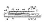
図5に示されるように、伝熱板45は第1LSIパッケージ21上のCPUチップ51に受け止められる。第1LSIパッケージ21は例えばPGA(ピングリッドアレイ)に基づきソケットを介してプリント基板19に固定されればよい。CPUチップ51および伝熱板45の間には熱拡散プレート52が挟み込まれる。熱拡散プレート52は例えば銅といった高熱伝導性の金属材料から形成されればよい。こうした熱拡散プレート52の働きでCPUチップ51から伝熱板45に効率的に熱は受け渡されることができる。  As shown in FIG. 5, theheat transfer plate 45 is received by theCPU chip 51 on thefirst LSI package 21. Thefirst LSI package 21 may be fixed to the printedcircuit board 19 via a socket based on, for example, PGA (pin grid array). Athermal diffusion plate 52 is sandwiched between theCPU chip 51 and theheat transfer plate 45. Thethermal diffusion plate 52 may be formed from a metal material having high thermal conductivity such as copper. Theheat diffusion plate 52 can efficiently transfer heat from theCPU chip 51 to theheat transfer plate 45.

筐体44は、流通路46の下流端および流出ノズル48の間で伝熱板45から窪む窪み53を備える。こうした窪み53に基づき筐体44は流通路46よりも低い空間54を区画する。空間54には流出ノズル48が臨む。こうして流出ノズル48は伝熱板45の縁に向き合う。同様に、筐体44では、流通路46の上流端および流入ノズル47、47の間で伝熱板45から窪む窪み53aが区画される。窪み53aに基づき流通路46よりも低い空間54aが区画される。空間54aには流入ノズル47、47が臨む。こうして流入ノズル47は伝熱板45の縁に向き合う。その一方で、筐体44には平板状の天板55が区画される。天板55は伝熱板45および窪み53、53aに向き合わせられる。  Thehousing 44 includes arecess 53 that is recessed from theheat transfer plate 45 between the downstream end of theflow passage 46 and theoutflow nozzle 48. Based on thedepression 53, thehousing 44 defines aspace 54 lower than theflow passage 46. Theoutflow nozzle 48 faces thespace 54. Thus, theoutflow nozzle 48 faces the edge of theheat transfer plate 45. Similarly, in thehousing 44, arecess 53 a that is recessed from theheat transfer plate 45 is defined between the upstream end of theflow passage 46 and theinflow nozzles 47 and 47. Aspace 54a lower than theflow passage 46 is defined based on therecess 53a.Inflow nozzles 47, 47 face thespace 54a. Thus, theinflow nozzle 47 faces the edge of theheat transfer plate 45. On the other hand, a flattop plate 55 is defined in thehousing 44. Thetop plate 55 is opposed to theheat transfer plate 45 and therecesses 53 and 53a.

こうした第1受熱器28では、窪み53、53aは流通路46の上流端や下流端と流入ノズル47や流出ノズル48との間に区画される。すなわち、空間54、54aは伝熱板45すなわち第1LSIパッケージ21の外側に配置される。こうした空間54、54aに流入ノズル47や流出ノズル48は臨む。その結果、流入ノズル47や流出ノズル48が第1LSIパッケージ21上で直接に流通路46に臨む場合に比べて、筐体44の厚みの増大は回避される。プリント基板19の表面から第1受熱器28の高さは抑制される。こうした第1受熱器28は本体筐体12の薄型化に大いに貢献することができる。  In thefirst heat receiver 28, therecesses 53 and 53 a are partitioned between the upstream end and the downstream end of theflow passage 46 and theinflow nozzle 47 and theoutflow nozzle 48. That is, thespaces 54 and 54 a are arranged outside theheat transfer plate 45, that is, thefirst LSI package 21. Theinflow nozzle 47 and theoutflow nozzle 48 face thespaces 54 and 54a. As a result, an increase in the thickness of thehousing 44 is avoided as compared with the case where theinflow nozzle 47 and theoutflow nozzle 48 directly face theflow path 46 on thefirst LSI package 21. The height of thefirst heat receiver 28 from the surface of the printedcircuit board 19 is suppressed. Such afirst heat receiver 28 can greatly contribute to the thinning of themain body housing 12.

筐体44では、伝熱板45は水平方向に広がる。空間54は流通路46よりも低いことから、重力の働きで冷媒は流路46から空間54に流れ込む。循環経路でポンプ38やホース41からの蒸発に基づき例えば冷媒が減少しても、冷媒は空間54に溜め込まれることができる。したがって、流通路46内に空気が混入したとしても、空間54内では空気は天板55側に集められる。その結果、流出ノズル48内に空気の進入はできる限り回避される。循環経路内で空気の流通は回避される。In thehousing 44, theheat transfer plate 45 extends in the horizontal direction.Space 54 from the lower than theflow passage 46, the refrigerant by the action of gravity flows into thespace 54 from the flowthroughpassage 46. Even if, for example, the refrigerant decreases based on evaporation from thepump 38 and thehose 41 in the circulation path, the refrigerant can be stored in thespace 54. Therefore, even if air enters theflow passage 46, the air is collected on thetop plate 55 side in thespace 54. As a result, entry of air into theoutflow nozzle 48 is avoided as much as possible. Air circulation is avoided in the circulation path.

図6に示されるように、ファン36はいわゆる遠心ファンに構成される。ファン36は、回転体56と、回転体56の周囲で回転体56から放射状に広がる複数枚の羽根57とを備える。ファン36が回転中心軸58回りで回転すると、ファンハウジング34の底板の吸気用開口35や天板の吸気用開口35から回転中心軸58に沿って空気は導入される。ファン36の回転で遠心方向に気流は生成される。  As shown in FIG. 6, thefan 36 is a so-called centrifugal fan. Thefan 36 includes arotator 56 and a plurality ofblades 57 that radiate from therotator 56 around therotator 56. When thefan 36 rotates about therotation center axis 58, air is introduced along therotation center axis 58 from theintake opening 35 on the bottom plate of thefan housing 34 and theintake opening 35 on the top plate. An air flow is generated in the centrifugal direction by the rotation of thefan 36.

ファンハウジング34には、ファン36の遠心方向外側に配置される送風口59が区画される。送風口59および排気口33の間には熱交換器31が配置される。遠心方向の気流はファンハウジング34の内面に沿って送風口59まで誘導される。こうして送風口59から気流は吐き出される。気流は熱交換器31を通過して排気口33に至る。熱交換器31は気流の流通方向に直交する方向に延びる。  Thefan housing 34 has ablower port 59 disposed outside thefan 36 in the centrifugal direction. Aheat exchanger 31 is disposed between theblower port 59 and theexhaust port 33. The centrifugal airflow is guided along the inner surface of thefan housing 34 to theair blowing port 59. In this way, the air current is discharged from theair blowing port 59. The airflow passes through theheat exchanger 31 and reaches theexhaust port 33. Theheat exchanger 31 extends in a direction perpendicular to the flow direction of the airflow.

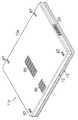
図7に示されるように、熱交換器31は、ベース12aの底面に平行に広がる第1平板61と、第1平板61の表面に向き合わせられる第2平板62とを備える。第2平板62は第1平板61に平行に広がる。第1および第2平板61、62の縁同士は結合される。こうして第1および第2平板61、62の間には第1平板61に沿って平たい空間63が区画される。空間63は冷媒の流通路として機能する。空間63は金属管42の中心軸に沿って広がる。第1および第2平板61、62は例えばアルミニウムといった熱伝導性の金属材料から形成される。  As shown in FIG. 7, theheat exchanger 31 includes a firstflat plate 61 that extends parallel to the bottom surface of the base 12 a and a secondflat plate 62 that faces the surface of the firstflat plate 61. The secondflat plate 62 extends in parallel to the firstflat plate 61. The edges of the first and secondflat plates 61 and 62 are joined together. Thus, aflat space 63 is defined between the first and secondflat plates 61 and 62 along the firstflat plate 61. Thespace 63 functions as a refrigerant flow path. Thespace 63 extends along the central axis of themetal tube 42. The first and secondflat plates 61 and 62 are made of a heat conductive metal material such as aluminum.

第1平板61の外向き面には複数枚の第1放熱フィン64が立ち上がる。第2平板62の外向き面には複数枚の第2放熱フィン65が立ち上がる。第1および第2放熱フィン64、65はファンユニット32の送風口59から排気口33に向かって延びる。こうして第1放熱フィン64、64同士の間や第2放熱フィン65、65同士の間には気流の流通路が区画される。気流は流通路や第1および第2平板61、62の外向き面に沿って流通する。第1および第2放熱フィン64、65は例えばアルミニウムといった熱伝導性の金属材料から形成される。  A plurality of firstheat radiation fins 64 rise on the outward surface of the firstflat plate 61. A plurality ofsecond radiating fins 65 rise on the outward surface of the secondflat plate 62. The first and second radiatingfins 64 and 65 extend from theblower port 59 of thefan unit 32 toward theexhaust port 33. Thus, an airflow passage is defined between thefirst radiating fins 64 and 64 and between thesecond radiating fins 65 and 65. The airflow flows along the outward passages of the flow passages and the first and secondflat plates 61 and 62. The first and second radiatingfins 64 and 65 are made of a heat conductive metal material such as aluminum.

図8に示されるように、空間63は平たく形成される。金属管42の断面積に比べて空間63では十分な断面積で冷媒の流通路が確保される。空間63では冷媒の流速は抑制される。こうして冷媒は空間63を比較的に緩やかに流れることができる。冷媒は長い時間にわたって第1および第2平板61、62に接触することができる。冷媒の熱は第1および第2平板61、62に十分に伝達されることができる。冷媒の熱は効率的に気流に受け渡されることができる。  As shown in FIG. 8, thespace 63 is formed flat. Compared to the cross-sectional area of themetal tube 42, the refrigerant 63 has a sufficient cross-sectional area in thespace 63. In thespace 63, the flow rate of the refrigerant is suppressed. Thus, the refrigerant can flow in thespace 63 relatively slowly. The refrigerant can contact the first and secondflat plates 61 and 62 for a long time. The heat of the refrigerant can be sufficiently transmitted to the first and secondflat plates 61 and 62. The heat of the refrigerant can be efficiently transferred to the airflow.

いま、冷媒が循環経路を循環する場面を想定する。前述されるように、冷媒には例えばプロピレングリコール系の不凍液が用いられる。ノートパソコン11の電源が入れられると、CPUチップ51はファンユニット32を稼働させる。ファン36は回転する。本体筐体12に形成される吸気口(図示されず)から外気が導入される。吸気用開口35から回転中心軸58に沿って空気は導入される。こうしてプリント基板19の表裏面に沿って気流は流通する。同時に、CPUチップ51はポンプ38を稼働させる。循環経路内で冷媒の流れは作り出される。  Now, assume that the refrigerant circulates in the circulation path. As described above, for example, propylene glycol antifreeze is used as the refrigerant. When the notebookpersonal computer 11 is powered on, theCPU chip 51 operates thefan unit 32. Thefan 36 rotates. Outside air is introduced from an air inlet (not shown) formed in themain body housing 12. Air is introduced from theintake opening 35 along therotation center axis 58. Thus, the airflow flows along the front and back surfaces of the printedcircuit board 19. At the same time, theCPU chip 51 operates thepump 38. A refrigerant flow is created in the circulation path.

CPUチップ51の処理動作中、CPUチップ51は第1発熱量で発熱する。CPUチップ51の熱は第1受熱器28の伝熱板45および放熱フィン49に受け渡される。伝熱板45や放熱フィン49の熱は流通路46内の冷媒に受け渡される。冷媒は2つの流入ノズル47、47から流通路46に流入する。こうして流通路46では2つの流れが生み出される。流通路46では冷媒の流れは大きく広がる。冷媒は流通路46内で淀みなく流れる。伝熱板45の熱は効率的に冷媒に受け渡されることができる。こうしてCPUチップ51は冷却される。  During the processing operation of theCPU chip 51, theCPU chip 51 generates heat with the first heat generation amount. The heat of theCPU chip 51 is transferred to theheat transfer plate 45 and theradiation fins 49 of thefirst heat receiver 28. The heat of theheat transfer plate 45 and theradiation fins 49 is transferred to the refrigerant in theflow passage 46. The refrigerant flows into theflow passage 46 from the twoinflow nozzles 47 and 47. In this way, two flows are produced in theflow passage 46. In theflow passage 46, the flow of the refrigerant greatly spreads. The refrigerant flows in theflow passage 46 without stagnation. The heat of theheat transfer plate 45 can be efficiently transferred to the refrigerant. Thus, theCPU chip 51 is cooled.

冷媒は第1受熱器28から第2受熱器29に流れる。ビデオチップの処理動作中、ビデオチップは、第1発熱量より小さい第2発熱量で発熱する。ビデオチップの熱は第2受熱器29の伝熱板に受け渡される。熱は伝熱板から金属管42内の冷媒に受け渡される。こうしてビデオチップは冷却される。冷媒は第2受熱器29から熱交換器31に流れる。ここでは、ビデオチップはCPUチップ51の第1発熱量より小さい第2発熱量で発熱することから、発熱量の大きいCPUチップ51が最初に冷却されることができる。こうしてCPUチップ51およびビデオチップは効率的に冷却されることができる。  The refrigerant flows from thefirst heat receiver 28 to thesecond heat receiver 29. During the processing operation of the video chip, the video chip generates heat with a second heat generation amount smaller than the first heat generation amount. The heat of the video chip is transferred to the heat transfer plate of thesecond heat receiver 29. Heat is transferred from the heat transfer plate to the refrigerant in themetal tube 42. Thus, the video chip is cooled. The refrigerant flows from thesecond heat receiver 29 to theheat exchanger 31. Here, since the video chip generates heat with a second heat generation amount smaller than the first heat generation amount of theCPU chip 51, theCPU chip 51 having a large heat generation amount can be cooled first. Thus, theCPU chip 51 and the video chip can be efficiently cooled.

熱交換器31では冷媒は空間63に流入する。冷媒の熱は第1および第2平板61、62や第1および第2放熱フィン64、65に受け渡される。ファンユニット32の働きで送風口59から排気口33に向かって気流は生み出される。冷媒の熱は第1および第2平板61、62の外向き面や第1および第2放熱フィン64、65の表面から大気中に放出される。冷媒は冷却される。気流は排気口33から本体筐体12の外側に吐き出される。冷媒はタンク37に流れる。その後、冷媒はタンク37からポンプ38に流れる。  In theheat exchanger 31, the refrigerant flows into thespace 63. The heat of the refrigerant is transferred to the first and secondflat plates 61 and 62 and the first andsecond radiation fins 64 and 65. An airflow is generated from theblower opening 59 toward theexhaust outlet 33 by the function of thefan unit 32. The heat of the refrigerant is released into the atmosphere from the outward surfaces of the first and secondflat plates 61 and 62 and the surfaces of the first and second radiatingfins 64 and 65. The refrigerant is cooled. The airflow is discharged from theexhaust port 33 to the outside of themain housing 12. The refrigerant flows into thetank 37. Thereafter, the refrigerant flows from thetank 37 to thepump 38.

以上のようなノートパソコン11では、本体筐体12の収容空間に液冷ユニット27が配置される。ディスプレイ用筐体13には液冷ユニット27の構成部品は組み込まれない。ホース41や金属管42が本体筐体12およびディスプレイ用筐体13の間で行き来する必要はない。ノートパソコン11の組立にあたって、液冷ユニット27は簡単に本体筐体12に組み込まれることができる。組立コストは抑制されることができる。同様に、液冷ユニット27は本体筐体12から簡単に取り外されることができる。  In thenotebook computer 11 as described above, theliquid cooling unit 27 is disposed in the housing space of themain body housing 12. Components of theliquid cooling unit 27 are not incorporated in thedisplay housing 13. Thehose 41 and themetal pipe 42 do not need to go back and forth between themain body housing 12 and thedisplay housing 13. In assembling thenotebook computer 11, theliquid cooling unit 27 can be easily incorporated into themain body housing 12. Assembly costs can be reduced. Similarly, theliquid cooling unit 27 can be easily detached from themain body housing 12.

しかも、ノートパソコン11は本体筐体12で例えば机上に設置される。前述の図1から明らかなように、ディスプレイ用筐体13は、水平姿勢を確立する本体筐体12の一端に沿って傾斜姿勢を確立する。液冷ユニット27が本体筐体12に組み込まれれば、液冷ユニット27の重量でノートパソコン11の重心は低く設定されることができる。ノートパソコン11の姿勢は安定することができる。  In addition, thenotebook computer 11 is installed on the desk, for example, on themain body housing 12. As is clear from FIG. 1 described above, thedisplay housing 13 establishes an inclined posture along one end of themain body housing 12 that establishes a horizontal posture. If theliquid cooling unit 27 is incorporated into themain body housing 12, the center of gravity of thenotebook computer 11 can be set low by the weight of theliquid cooling unit 27. The posture of thenotebook computer 11 can be stabilized.

加えて、液冷ユニット27では、第1受熱器28、第2受熱器29、熱交換器31、タンク37、金属管42はすべてアルミニウムから形成される。したがって、循環経路内で冷媒はアルミニウム以外の金属材料に接触しない。冷媒に金属イオンの溶出は回避される。第1受熱器28や第2受熱器29、熱交換器31、タンク37、金属管42の浸食は防止される。循環経路から液漏れは回避される。In addition, in theliquid cooling unit 27, thefirst heat receiver 28, thesecond heat receiver 29, theheat exchanger 31, thetank 37, and themetal pipe 42 are all formed from aluminum. Therefore, the refrigerant does not contact any metal material other than aluminum in the circulation path. The elution of metal ions in the refrigerant is avoided. Thefirst heat receiver 28, thesecond heat receiver 29, theheat exchanger 31, thetank37, the erosion of themetals tube 42 is prevented. Liquid leakage from the circulation path is avoided.

さらに、熱交換器31では、円筒状の管で冷媒の流通路が区画される場合に比べて、第1平板61や第2平板62は大きな面積で第1放熱フィン64や第2放熱フィン65に接触することができる。放熱の効率は高められることができる。さらにまた、空間63は金属管42の中心軸に沿って広がる。たとえ冷媒の量が減少しても、金属管42から空間63に空気の流入は回避される。冷媒は第2平板62に沿って流れることができる。放熱の効率は高められる。その一方で、第1および第2平板61、62に比べて円筒状の管は気流の流通を妨げてしまう。  Further, in theheat exchanger 31, the firstflat plate 61 and the secondflat plate 62 have a larger area than the case where the refrigerant flow path is defined by a cylindrical tube, and thefirst radiating fins 64 and thesecond radiating fins 65. Can contact. The efficiency of heat dissipation can be increased. Furthermore, thespace 63 extends along the central axis of themetal tube 42. Even if the amount of the refrigerant decreases, the inflow of air from themetal pipe 42 to thespace 63 is avoided. The refrigerant can flow along the secondflat plate 62. The efficiency of heat dissipation is increased. On the other hand, compared to the first and secondflat plates 61 and 62, the cylindrical tube hinders the flow of airflow.

図9に示されるように、第1受熱器28では、流入ノズル47の先端は例えば横長に広がってもよい。ここでは、流入ノズル47の先端は伝熱板45や天板55に沿って横長に広がればよい。こうした流入ノズル47によれば、冷媒は流入ノズル47の先端から流路46に横長に広がりつつ流入することができる。流通路46では冷媒の流れは一層大きく広がることができる。伝熱板45や放熱フィン49から冷媒に一層効率的に熱は受け渡されることができる。As shown in FIG. 9, in thefirst heat receiver 28, the tip of theinflow nozzle 47 may spread horizontally, for example. Here, the tip of theinflow nozzle 47 only needs to extend horizontally along theheat transfer plate 45 and thetop plate 55. According tosuch inflow nozzles 47, the coolant can flow while spreading horizontally to flowthroughpassage 46 from the distal end of theinflow nozzles 47. In theflow passage 46, the flow of the refrigerant can be further expanded. Heat can be transferred from theheat transfer plate 45 and theheat radiation fins 49 to the refrigerant more efficiently.

図10に示されるように、液冷ユニット27は前述の熱交換器31に代えて熱交換器31aを備えてもよい。熱交換器31aは、前述の第1および第2平板61、62に加えて、第3および第4平板66、67をさらに備える。第3平板66は第2平板62の表面に向き合わせられる。第4平板67は第3平板66の表面に向き合わせられる。第3および第4平板66、67の縁同士は結合される。こうして第3および第4平板66、67の間には第3平板66に沿って平たい空間68が区画される。空間68は冷媒の流通路として機能する。第3および第4平板66、67は例えばアルミニウムといった熱伝導性の金属材料から形成される。  As shown in FIG. 10, theliquid cooling unit 27 may include aheat exchanger 31 a instead of the above-describedheat exchanger 31. Theheat exchanger 31a further includes third and fourthflat plates 66 and 67 in addition to the first and secondflat plates 61 and 62 described above. The thirdflat plate 66 is opposed to the surface of the secondflat plate 62. The fourthflat plate 67 is opposed to the surface of the thirdflat plate 66. The edges of the third and fourthflat plates 66 and 67 are joined together. Thus, aflat space 68 is defined along the thirdflat plate 66 between the third and fourthflat plates 66 and 67. Thespace 68 functions as a refrigerant flow path. The third and fourthflat plates 66 and 67 are made of a heat conductive metal material such as aluminum.

前述の熱交換器31と同様に、第1平板61の外向き面には複数枚の第1放熱フィン64が立ち上がる。その一方で、複数枚の第2放熱フィン65は第4平板67の外向き面から立ち上がる。こうして第2平板62の表面および第3平板66の裏面の間には隙間が区画される。こうした隙間はファンユニット32の送風口59から排気口33に向かって気流の流通路として機能する。  Similar to theheat exchanger 31 described above, a plurality of firstheat radiation fins 64 rise on the outward surface of the firstflat plate 61. On the other hand, the plurality of secondheat radiation fins 65 rise from the outward surface of the fourthflat plate 67. Thus, a gap is defined between the front surface of the secondflat plate 62 and the back surface of the thirdflat plate 66. Such a gap functions as a flow path for the airflow from theair blowing port 59 of thefan unit 32 toward theexhaust port 33.

第2平板62の表面および第3平板66の裏面の隙間には支柱69、69が配置される。支柱69は第2平板62および第3平板66に受け止められる。こうして支柱69は第2平板62および第3平板66の隙間を維持する。こうして熱交換器31aの製造時、第1平板61および第4平板67すなわち第2平板62および第3平板66に相互に近づく方向に力が加えられても、第1〜第4平板61、62、66、67の撓みは回避される。撓みに基づく当該隙間の断面積の減少は回避される。Supports 69 and 69 are arranged in the gap between the front surface of the secondflat plate 62 and the back surface of the thirdflat plate 66. Thecolumn 69 is received by the secondflat plate 62 and the thirdflat plate 66. Thus, thesupport 69 maintains the gap between the secondflat plate 62 and the thirdflat plate 66. Thus, even when a force is applied to the firstflat plate 61 and the fourthflat plate 67, that is, the secondflat plate 62 and the thirdflat plate 66, when theheat exchanger 31a is manufactured, the first to fourthflat plates 61 and 62 are applied. , 66, 67 are avoided. A reduction in the cross-sectional area of thegap due to deflection is avoided.

こういった熱交換器31aでは、相互に並列に2つの空間63、68が区画される。空間63、68内で冷媒は流通する。前述の熱交換器31に比べて流通路の断面積は増大することができる。断面積の増大に基づき冷媒の流速は低下する。冷媒は空間63、68を一層緩やかに流れることができる。冷媒は長い時間にわたって第1および第2平板61、62並びに第3および第4平板66、67に接触する。冷媒の熱は第1および第2平板61、62並びに第3および第4平板66、67に十分に伝達される。冷媒の熱は効率的に気流に受け渡される。  In such aheat exchanger 31a, twospaces 63 and 68 are partitioned in parallel with each other. The refrigerant circulates in thespaces 63 and 68. Compared to theheat exchanger 31 described above, the cross-sectional area of the flow passage can be increased. As the cross-sectional area increases, the flow rate of the refrigerant decreases. The refrigerant can flow through thespaces 63 and 68 more gently. The refrigerant contacts the first and secondflat plates 61 and 62 and the third and fourthflat plates 66 and 67 for a long time. The heat of the refrigerant is sufficiently transmitted to the first and secondflat plates 61 and 62 and the third and fourthflat plates 66 and 67. The heat of the refrigerant is efficiently transferred to the airflow.

しかも、第2平板62および第3平板66の間に区画される隙間には気流が流れ込むことができる。こうした気流は第2平板62の表面および第3平板66の裏面に沿って流通する。その結果、第2平板62の表面および第3平板66の裏面から大気中に熱が放出される。前述の熱交換器31に比べて、放熱の効率は高められることができる。  In addition, airflow can flow into the gap defined between the secondflat plate 62 and the thirdflat plate 66. Such airflow flows along the front surface of the secondflat plate 62 and the back surface of the thirdflat plate 66. As a result, heat is released into the atmosphere from the front surface of the secondflat plate 62 and the back surface of the thirdflat plate 66. Compared with theheat exchanger 31 described above, the efficiency of heat dissipation can be increased.

図11に示されるように、液冷ユニット27は前述の熱交換器31、31aに代えて熱交換器31bを備えてもよい。この熱交換器31bは、熱交換器31aの第1および第2平板61、62並びに第3および第4平板66、67に加えて、第5および第6平板71、72をさらに備える。第5平板71は第2平板62の表面に向き合わせられる。第6平板72は第5平板71の表面に向き合わせられる。同時に、第6平板72は第3平板66の裏面に向き合わせられる。第5および第6平板71、72の縁同士は結合される。こうして第5および第6平板71、72の間には第5平板71に沿って平たい空間73が区画される。空間73は冷媒の流通路として機能する。第5および第6平板71、72は例えばアルミニウムといった熱伝導性の金属材料から形成される。  As shown in FIG. 11, theliquid cooling unit 27 may include aheat exchanger 31b instead of the above-describedheat exchangers 31 and 31a. Theheat exchanger 31b further includes fifth and sixthflat plates 71 and 72 in addition to the first and secondflat plates 61 and 62 and the third and fourthflat plates 66 and 67 of theheat exchanger 31a. The fifthflat plate 71 is opposed to the surface of the secondflat plate 62. The sixthflat plate 72 is opposed to the surface of the fifthflat plate 71. At the same time, the sixthflat plate 72 faces the back surface of the thirdflat plate 66. The edges of the fifth and sixthflat plates 71 and 72 are joined together. Thus, aflat space 73 is defined along the fifthflat plate 71 between the fifth and sixthflat plates 71 and 72. Thespace 73 functions as a refrigerant flow path. The fifth and sixthflat plates 71 and 72 are made of a heat conductive metal material such as aluminum.

前述の熱交換器31aと同様に、第1平板61の外向き面には複数枚の第1放熱フィン64が立ち上がる。第4平板67の外向き面には複数枚の第2放熱フィン65が立ち上がる。こうして第2平板62の表面および第5平板71の裏面の間には隙間が区画される。同時に、第6平板72の表面および第3平板66の裏面の間には隙間が区画される。こうした2つの隙間はファンユニット32の送風口59から排気口33に向かって気流の流通路として機能する。隙間には前述と同様に支柱69、69が配置されればよい。  Similar to theheat exchanger 31 a described above, a plurality of firstheat radiation fins 64 rise on the outward surface of the firstflat plate 61. A plurality ofsecond radiating fins 65 rise on the outward surface of the fourthflat plate 67. Thus, a gap is defined between the front surface of the secondflat plate 62 and the back surface of the fifthflat plate 71. At the same time, a gap is defined between the front surface of the sixthflat plate 72 and the back surface of the thirdflat plate 66. These two gaps function as airflow passages from theair outlet 59 of thefan unit 32 toward theair outlet 33. It is only necessary that thesupport columns 69 are disposed in the gap as described above.

こうした熱交換器31bでは、相互に並列に3つの空間63、68、73が区画される。空間63、68、73内で冷媒は流通する。前述の熱交換器31、31aに比べて流通路の断面積は増大することができる。前述に比べて、冷媒は空間63、68、73を一層緩やかに流れる。前述と同様に、冷媒の熱は効率的に気流に受け渡されることができる。こうして熱交換器31、31a、31bでは、空間63、68、73の数に基づき冷媒の流速は調整されることができる。しかも、2つの隙間には気流が流れ込むことができる。前述の熱交換器31、31aに比べて、放熱の効率は高められることができる。  In such aheat exchanger 31b, threespaces 63, 68, 73 are partitioned in parallel with each other. The refrigerant circulates in thespaces 63, 68, 73. Compared to theheat exchangers 31 and 31a described above, the cross-sectional area of the flow passage can be increased. Compared with the above, the refrigerant flows more gently in thespaces 63, 68, 73. As described above, the heat of the refrigerant can be efficiently transferred to the airflow. In this way, in theheat exchangers 31, 31a, 31b, the flow rate of the refrigerant can be adjusted based on the number ofspaces 63, 68, 73. Moreover, airflow can flow into the two gaps. Compared with theheat exchangers 31 and 31a described above, the efficiency of heat dissipation can be increased.

図12に示されるように、液冷ユニット27は、前述の熱交換器31、31a、31bに代えて、熱交換器31cを備えてもよい。この熱交換器31cでは、前述の熱交換器31の第1および第2平板61、62が冷媒の流通方向に2つに分割される。すなわち、熱交換器31cは、基準平面に沿って広がる第1平板74と、第1平板74の表面に向き合わせられる第2平板75とを備える。第1および第2平板74、75の間には平たい空間76が区画される。空間76は冷媒の流通路として機能する。第1および第2平板74、75は例えばアルミニウムといった熱伝導性の金属材料から形成される。  As shown in FIG. 12, theliquid cooling unit 27 may include aheat exchanger 31c instead of the above-describedheat exchangers 31, 31a, 31b. In theheat exchanger 31c, the first and secondflat plates 61 and 62 of theheat exchanger 31 are divided into two in the refrigerant flow direction. That is, theheat exchanger 31 c includes a firstflat plate 74 that extends along the reference plane and a secondflat plate 75 that faces the surface of the firstflat plate 74. Aflat space 76 is defined between the first and secondflat plates 74 and 75. Thespace 76 functions as a refrigerant flow path. The first and secondflat plates 74 and 75 are made of a heat conductive metal material such as aluminum.

同様に、熱交換器31cは、第3平板77と、第3平板77の表面に向き合わせられる第4平板78とを備える。第3平板77は前述の基準平面に沿って広がる。第3および第4平板77、78の間には平たい空間79が区画される。空間79は冷媒の流通路として機能する。空間79は空間76に並列に延びる。ここでは、送風口59から排気口33に向かう気流の流通方向に沿って規定される空間76の長さL1は、同様に規定される空間79の長さL2に等しく設定されればよい。第3および第4平板77、78は例えばアルミニウムといった熱伝導性の金属材料から形成される。  Similarly, theheat exchanger 31 c includes a thirdflat plate 77 and a fourthflat plate 78 that faces the surface of the thirdflat plate 77. The thirdflat plate 77 extends along the aforementioned reference plane. Aflat space 79 is defined between the third and fourthflat plates 77 and 78. Thespace 79 functions as a refrigerant flow path. Thespace 79 extends in parallel to thespace 76. Here, the length L1 of thespace 76 defined along the flow direction of the airflow from theblower port 59 to theexhaust port 33 may be set equal to the length L2 of thespace 79 similarly defined. The third and fourthflat plates 77 and 78 are made of a heat conductive metal material such as aluminum.

図13に示されるように、液冷ユニット27では、熱交換器31cに代えて、熱交換器31dが用いられてもよい。この熱交換器31dでは、前述の熱交換器31cの空間76、79の長さL1、L2が変更される。ここでは、空間79の長さL2は空間76の長さL1よりも大きく設定されればよい。ただし、空間79の長さL2が空間76の長さL1よりも小さく設定されてもよい。  As shown in FIG. 13, in theliquid cooling unit 27, aheat exchanger 31d may be used instead of theheat exchanger 31c. In theheat exchanger 31d, the lengths L1 and L2 of thespaces 76 and 79 of theheat exchanger 31c described above are changed. Here, the length L <b> 2 of thespace 79 may be set larger than the length L <b> 1 of thespace 76. However, the length L2 of thespace 79 may be set smaller than the length L1 of thespace 76.

図14は本発明の第2実施形態に係る電子機器の一具体例すなわちノートパソコン11aの内部構造を概略的に示す。このノートパソコン11aでは、本体筐体12の収容空間に液冷ユニット27aが配置される。液冷ユニット27aは、前述の第1受熱器28、第2受熱器29および熱交換器31に代えて、第1受熱器81、第2受熱器82および熱交換器83を備える。液冷ユニット27aでは第1受熱器81から一巡する循環経路が区画される。その他、前述のノートパソコン11と均等な構成や構造には同一の参照符号が付される。  FIG. 14 schematically shows an example of the electronic apparatus according to the second embodiment of the present invention, that is, the internal structure of thenotebook computer 11a. In the notebookpersonal computer 11 a, aliquid cooling unit 27 a is disposed in the housing space of themain body housing 12. Theliquid cooling unit 27a includes afirst heat receiver 81, asecond heat receiver 82, and aheat exchanger 83 in place of thefirst heat receiver 28, thesecond heat receiver 29, and theheat exchanger 31 described above. In theliquid cooling unit 27a, a circulation path that makes a round from thefirst heat receiver 81 is defined. Like reference numerals are attached to the structure or components equivalent to those of theaforementioned notebook computer 11.

液冷ユニット27aでは、ファンユニット32は冷媒の循環経路の外側に配置される。タンク37およびポンプ38はプリント基板19の外側に配置される。タンク37はプリント基板19およびDVD駆動装置23の間に配置される。ポンプ38はプリント基板19およびHDD24の間に配置される。タンク37やポンプ38は例えばベース12aの底板にねじ留めされればよい。なお、ベース12aの底板に例えば開口(図示されず)が区画されれば、タンク37やポンプ38はベース12aの底面側から交換されることができる。In theliquid cooling unit 27a, thefan unit 32 is disposed outside the refrigerant circulation path. Thetank 37 and thepump 38 are disposed outside the printedcircuit board 19. Thetank 37 is disposed between the printedcircuit board 19 and theDVD drive device 23 . Thepump 38 is disposed between the printedcircuit board 19 and theHDD 24 . Thetank 37 and thepump 38 may be screwed to the bottom plate of thebase 12a, for example. For example, if an opening (not shown) is defined in the bottom plate of thebase 12a, thetank 37 and thepump 38 can be replaced from the bottom surface side of thebase 12a.

タンク37およびポンプ38とプリント基板19との間には仕切り板84が配置される。仕切り板84はベース12aの底板から直立すればよい。仕切り板84は、プリント基板19の収容空間と、タンク37およびポンプ38の収容空間とを仕切る。その結果、プリント基板19の収容空間と、タンク37およびポンプ38の収容空間との間で空気の移動は抑制される。その結果、タンク37およびポンプ38の収容空間に、第1および第2LSIパッケージ21、22の熱を帯びた空気の進入は回避される。タンク37やポンプ38の温度上昇は回避される。ポンプ38から冷媒の蒸発は抑制される。  Apartition plate 84 is disposed between thetank 37 and thepump 38 and the printedcircuit board 19. Thepartition plate 84 may be upright from the bottom plate of thebase 12a. Thepartition plate 84 partitions the accommodation space for the printedcircuit board 19 and the accommodation spaces for thetank 37 and thepump 38. As a result, the movement of air between the accommodation space of the printedcircuit board 19 and the accommodation space of thetank 37 and thepump 38 is suppressed. As a result, the entry of the heated air of the first and second LSI packages 21 and 22 into the storage space of thetank 37 and thepump 38 is avoided. The temperature rise of thetank 37 and thepump 38 is avoided. The evaporation of the refrigerant from thepump 38 is suppressed.

図15に示されるように、ベース12aの底板には第1吸気口85および第2吸気口86が区画される。第1および第2吸気口85、86は本体筐体12外側の空間から本体筐体12内側の空間に空気を導入する。ここでは、第1吸気口85は本体筐体12内でタンク37に向き合わせられる。第2吸気口86は本体筐体12内でポンプ38に向き合わせられる。こうしてタンク37やポンプ38は本体筐体12外側の外気に曝されることができる。第1および第2吸気口85、86は一体化されてもよい。  As shown in FIG. 15, afirst intake port 85 and asecond intake port 86 are defined in the bottom plate of thebase 12a. The first andsecond intake ports 85 and 86 introduce air from the space outside themain body housing 12 to the space inside themain body housing 12. Here, thefirst air inlet 85 faces thetank 37 in themain body housing 12. Thesecond intake port 86 is opposed to thepump 38 in themain body housing 12. Thus, thetank 37 and thepump 38 can be exposed to the outside air outside themain body housing 12. The first andsecond intake ports 85 and 86 may be integrated.

本体筐体12の底面の四隅にはパッド87が固定される。パッド87は本体筐体12の底面から突き出る。こうしたパッド87は例えばゴムといった弾性樹脂材料から形成されればよい。ノートパソコン11aが机上に設置されると、本体筐体12はパッド87で机の表面に受け止められる。その結果、本体筐体12の底面および机の表面の間に隙間が形成されることができる。第1および第2吸気口85、86の遮蔽は回避されることができる。  Pads 87 are fixed to the four corners of the bottom surface of themain housing 12. Thepad 87 protrudes from the bottom surface of themain body housing 12. Such apad 87 may be formed of an elastic resin material such as rubber. When thenotebook computer 11a is installed on the desk, themain body housing 12 is received by thepad 87 on the surface of the desk. As a result, a gap can be formed between the bottom surface of themain body housing 12 and the surface of the desk. Shielding of the first andsecond inlets 85, 86 can be avoided.

図16に示されるように、第1受熱器81では、流入ノズル47、47および流出ノズル48は相互に向き合う。こうして伝熱板45上には、流入ノズル47、47から流出ノズル48に向かって真っ直ぐに流通路46が区画される。図17に示されるように、流入ノズル47は空間54aに臨む。流出ノズル48は空間54に臨む。こうして、前述と同様に、流入ノズル47および流出ノズル48は第1LSIパッケージ21の外側で流通路46に接続される。筐体44の厚みの増大は回避される。  As shown in FIG. 16, in thefirst heat receiver 81, theinflow nozzles 47, 47 and theoutflow nozzle 48 face each other. Thus, on theheat transfer plate 45, theflow passage 46 is partitioned straight from theinflow nozzles 47, 47 toward theoutflow nozzle 48. As shown in FIG. 17, theinflow nozzle 47 faces thespace 54a. Theoutflow nozzle 48 faces thespace 54. Thus, theinflow nozzle 47 and theoutflow nozzle 48 are connected to theflow path 46 outside thefirst LSI package 21 as described above. An increase in the thickness of thehousing 44 is avoided.

図18に示されるように、熱交換器83では、前述の熱交換器31cと同様に、相互に並列に延びる空間76、79が区画される。ただし、1対の金属管42が熱交換器83の一方の側面に接続される。こうして冷媒は一方の金属管42から空間79に流入する。空間79から空間76に冷媒は流れる。冷媒は空間76から他方の金属管42に流入する。こうして冷媒は長い時間にわたって第1および第2平板74、75並び第3および第4平板76、77に接触することができる。同時に、冷媒の流通路は細分化される。流通路内で冷媒は淀みなく流れることができる。冷媒の熱は効率的に気流に受け渡される。  As shown in FIG. 18, in theheat exchanger 83,spaces 76 and 79 extending in parallel with each other are partitioned in the same manner as theheat exchanger 31 c described above. However, a pair ofmetal tubes 42 is connected to one side surface of theheat exchanger 83. In this way, the refrigerant flows into thespace 79 from the onemetal pipe 42. The refrigerant flows from thespace 79 to thespace 76. The refrigerant flows into theother metal pipe 42 from thespace 76. Thus, the refrigerant can contact the first and secondflat plates 74 and 75 and the third and fourthflat plates 76 and 77 for a long time. At the same time, the refrigerant flow path is subdivided. The refrigerant can flow without stagnation in the flow path. The heat of the refrigerant is efficiently transferred to the airflow.

こうして空間76、79が並列に区画されれば、冷媒の流通路の確立にあたって1対の金属管42、42が熱交換器83の一方の側面に接続されれば足りる。熱交換器83では他方の側面に金属管42が連結される必要はない。熱交換器83の小型化は実現されることができる。同時に、プリント基板19上で電子部品の配置に応じて金属管42の配置は変更されることができる。本体筐体12の収容空間で電子部品は様々な配置をとることができる。  Thus, if thespaces 76 and 79 are partitioned in parallel, it is sufficient that the pair ofmetal tubes 42 and 42 are connected to one side surface of theheat exchanger 83 in establishing the refrigerant flow passage. In theheat exchanger 83, themetal tube 42 does not need to be connected to the other side surface. Miniaturization of theheat exchanger 83 can be realized. At the same time, the arrangement of themetal tubes 42 can be changed according to the arrangement of the electronic components on the printedcircuit board 19. The electronic components can be arranged in various ways in the housing space of themain body housing 12.

以上のようなノートパソコン11aでは、前述のノートパソコン11と同様に、ポンプ38の働きで循環経路に冷媒が循環する。CPUチップ51の熱は第1受熱器81に受け渡される。ビデオチップの熱は第2受熱器82に受け渡される。冷媒の温度は上昇する。冷媒は第2受熱器82から熱交換器83に導入される。熱交換器83では、冷媒の熱は大気中に放出される。冷媒は冷却される。気流は排気口33から本体筐体12の外側に吐き出される。冷却後の冷媒はタンク37に導入される。  In thenotebook computer 11a as described above, the refrigerant circulates in the circulation path by the action of thepump 38, as in the above-describednotebook computer 11. The heat of theCPU chip 51 is transferred to thefirst heat receiver 81. The heat of the video chip is transferred to thesecond heat receiver 82. The temperature of the refrigerant rises. The refrigerant is introduced from thesecond heat receiver 82 into theheat exchanger 83. In theheat exchanger 83, the heat of the refrigerant is released into the atmosphere. The refrigerant is cooled. The airflow is discharged from theexhaust port 33 to the outside of themain housing 12. The cooled refrigerant is introduced into thetank 37.

同時に、CPUチップ51の熱やビデオチップの熱はプリント基板19に受け渡される。プリント基板19内の配線パターンを介して熱はプリント基板19内に広がる。タンク37やポンプ38はプリント基板19の外側に配置されることから、タンク37やポンプ38にこうした熱は伝達されない。タンク37内の冷媒やポンプ38内の冷媒の温度上昇は回避される。タンク37やポンプ38では冷媒の熱は本体筐体12内に放出されることができる。  At the same time, the heat of theCPU chip 51 and the heat of the video chip are transferred to the printedcircuit board 19. Heat spreads in the printedcircuit board 19 through the wiring pattern in the printedcircuit board 19. Since thetank 37 and thepump 38 are disposed outside the printedcircuit board 19, such heat is not transmitted to thetank 37 and thepump 38. Temperature rises of the refrigerant in thetank 37 and the refrigerant in thepump 38 are avoided. In thetank 37 and thepump 38, the heat of the refrigerant can be released into themain body housing 12.

しかも、タンク37やポンプ38には第吸気口8や第吸気口8が向き合わせられる。第1吸気口85や第2吸気口86から本体筐体12内に外気が導入される。タンク37やポンプ38は外気に曝される。タンク37内の冷媒やポンプ38内の冷媒の熱はタンク37やポンプ38から外気中に放出される。熱交換器83に加えてタンク37やポンプ38でも冷媒の熱は大気中に放出されることができる。冷媒は一層効率的に冷却されることができる。Moreover, thefirst intake port8 5 and thesecond intake port8 6 is opposed to thetank 37 andpump 38. Outside air is introduced into themain body housing 12 from thefirst air inlet 85 and thesecond air inlet 86. Thetank 37 and thepump 38 are exposed to the outside air. Heat of the refrigerant in thetank 37 and the refrigerant in thepump 38 is released from thetank 37 and thepump 38 into the outside air. In addition to theheat exchanger 83, thetank 37 and thepump 38 can release the heat of the refrigerant into the atmosphere. The refrigerant can be cooled more efficiently.

その他、図19に示されるように、熱交換器83では、前述の熱交換器31dと同様に、空間76、79の長さL1、L2は変更されてもよい。ここでは、空間79の長さL2は空間76の長さL1よりも大きく設定されればよい。ただし、空間79の長さL2は空間76の長さL1よりも小さく設定されてもよい。  In addition, as shown in FIG. 19, in theheat exchanger 83, the lengths L <b> 1 and L <b> 2 of thespaces 76 and 79 may be changed similarly to theheat exchanger 31 d described above. Here, the length L <b> 2 of thespace 79 may be set larger than the length L <b> 1 of thespace 76. However, the length L2 of thespace 79 may be set smaller than the length L1 of thespace 76.

以上のような冷却ユニット27、27aは、ノートパソコン11、11aに加えて、例えば携帯情報端末(PDA)やデスクトップパーソナルコンピュータ、サーバコンピュータといったその他の電子機器に組み込まれることができる。  In addition to the notebookpersonal computers 11 and 11a, the coolingunits 27 and 27a as described above can be incorporated into other electronic devices such as a personal digital assistant (PDA), a desktop personal computer, and a server computer.

本発明の第1実施形態に係る電子機器の一具体例すなわちノートブックパーソナルコンピュータ(ノートパソコン)の外観を概略的に示す斜視図である。1 is a perspective view schematically showing an external appearance of a specific example of an electronic apparatus according to a first embodiment of the present invention, that is, a notebook personal computer (notebook personal computer).ノートパソコンの内部構造を概略的に示す斜視図である。It is a perspective view which shows roughly the internal structure of a notebook personal computer.本発明の一実施形態に係る液冷ユニットの構造を概略的に示す平面図である。It is a top view which shows roughly the structure of the liquid cooling unit which concerns on one Embodiment of this invention.本発明の一具体例に係る受熱器の構造を概略的に示す断面図である。It is sectional drawing which shows roughly the structure of the heat receiver which concerns on one specific example of this invention.図4の5−5線に沿った断面図である。FIG. 5 is a cross-sectional view taken along line 5-5 of FIG.ファンユニットの構造を概略的に示す部分断面図である。It is a fragmentary sectional view showing roughly the structure of a fan unit.図6の7−7線に沿った断面図であり、本発明の一具体例に係る熱交換器の構造を概略的に示す図である。FIG. 7 is a cross-sectional view taken along line 7-7 in FIG. 6, schematically showing the structure of the heat exchanger according to one specific example of the present invention.図7の8−8線に沿った断面図である。FIG. 8 is a cross-sectional view taken along line 8-8 in FIG. 7.流入ノズルの構造を概略的に示す図である。It is a figure which shows the structure of an inflow nozzle roughly.図7に対応し、本発明の他の具体例に係る熱交換器の構造を概略的に示す断面図である。FIG. 9 is a cross-sectional view schematically showing a structure of a heat exchanger according to another specific example of the present invention, corresponding to FIG. 7.図7に対応し、本発明のさらに他の具体例に係る熱交換器の構造を概略的に示す断面図である。FIG. 10 is a cross-sectional view schematically showing a structure of a heat exchanger according to still another specific example of the present invention, corresponding to FIG. 7.図8に対応し、本発明のさらに他の具体例に係る熱交換器の構造を概略的に示す断面図である。FIG. 9 is a cross-sectional view schematically showing a structure of a heat exchanger according to still another specific example of the present invention, corresponding to FIG. 8.図8に対応し、本発明のさらに他の具体例に係る熱交換器の構造を概略的に示す断面図である。FIG. 9 is a cross-sectional view schematically showing a structure of a heat exchanger according to still another specific example of the present invention, corresponding to FIG. 8.本発明の第2実施形態に係るノートパソコンの内部構造を概略的に示す斜視図である。It is a perspective view which shows roughly the internal structure of the notebook computer which concerns on 2nd Embodiment of this invention.本体筐体の構造を概略的に示す斜視図である。It is a perspective view which shows the structure of a main body housing | casing roughly.図4に対応し、本発明の他の具体例に係る受熱器の構造を概略的に示す断面図である。FIG. 5 is a cross-sectional view schematically showing a structure of a heat receiver according to another specific example of the present invention, corresponding to FIG. 4.図16の17−17線に沿った断面図である。FIG. 17 is a cross-sectional view taken along line 17-17 in FIG.図8に対応し、本発明のさらに他の具体例に係る熱交換器の構造を概略的に示す断面図である。FIG. 9 is a cross-sectional view schematically showing a structure of a heat exchanger according to still another specific example of the present invention, corresponding to FIG. 8.図8に対応し、本発明のさらに他の具体例に係る熱交換器の構造を概略的に示す断面図である。FIG. 9 is a cross-sectional view schematically showing a structure of a heat exchanger according to still another specific example of the present invention, corresponding to FIG. 8.

符号の説明Explanation of symbols

11、11a 電子機器(ノートブックパーソナルコンピュータ)、19 プリント基板、21 電子部品、22 電子部品、31 熱交換器、37 タンク、38 ポンプ、45 伝熱板、46 流通路、81 受熱器、82 受熱器、84 仕切り板。  11, 11a Electronic device (notebook personal computer), 19 Printed circuit board, 21 Electronic component, 22 Electronic component, 31 Heat exchanger, 37 Tank, 38 Pump, 45 Heat transfer plate, 46 Flow path, 81 Heat receiver, 82Heat receiver 84, partition plate.

Claims (5)

Translated fromJapanese
本体筐体と、前記本体筐体に対して開閉自在に前記本体筐体に連結されるディスプレイ用筐体と、前記本体筐体に収容され、電子部品が実装されたプリント基板と、前記本体筐体内に収容され、伝熱板で前記電子部品に受け止められて、前記伝熱板上に冷媒の流通路を区画する受熱器と、前記本体筐体内に収容され、前記受熱器から一巡する循環経路と、前記本体筐体内に収容され、前記循環経路に組み入れられて、前記冷媒から熱を奪う熱交換器と、前記本体筐体内で前記プリント基板の輪郭の外側に配置されつつ前記循環経路に組み入れられて、前記循環経路内の空気を貯蔵するタンクとを備えることを特徴とする電子機器。A main body case,a display case connected to the main body case so as to be openable and closable with respect to the main body case, a printed circuit board housed in the main body caseand mounted with electronic components, and themain body case housed in the body, are received on the electronic component with heat transfer plate, a heat receiver defining a flow passage on the heat transfer plate,it is accommodated in the main body casing, the circulation path to cycle from the heat receiver And a heat exchangerhoused in the main body casing and incorporated in the circulation path to take heat away from the refrigerant, and incorporated in the circulation path while being disposed outside theoutline of the printed circuit board in the main body casing. And a tank that stores air in the circulation path. 請求項1に記載の電子機器において、前記プリント基板の輪郭の外側に配置されつつ前記循環経路に組み入れられて、前記循環経路で冷媒を循環させるポンプをさらに備える特徴とする電子機器。2. The electronic device according to claim 1, further comprising a pump that is arranged outside theoutline of the printed circuit board and is incorporated in the circulation path to circulate a refrigerant in the circulation path. 請求項1または2に記載の電子機器において、前記本体筐体内に収容され、前記タンクおよび前記プリント基板の間に配置される仕切り板と、前記本体筐体に形成され、前記タンクに向き合わせられる吸気口と、前記本体筐体に収容され、前記吸気口から導入され前記仕切り板を通過して前記プリント基板に沿って流れる気流を生成するファンユニットとをさらに備えることを特徴とする電子機器。3. The electronic device according to claim 1,wherein the electronic deviceis housed in themain body casing, is formed between the tank and the printed circuit board, is formed in the main body casing, and is opposed to the tank. An electronic apparatus, furthercomprising: an air inlet; and a fan unit that is housed in the main body housing and that is introduced from the air inlet and passes through the partition plate to generate an airflow that flows along the printed circuit board . 本体筐体と、前記本体筐体に対して開閉自在に前記本体筐体に連結されるディスプレイ用筐体と、前記本体筐体に収容され、電子部品が実装されたプリント基板と、前記本体筐体内に収容され、伝熱板で前記電子部品に受け止められて、前記伝熱板上に冷媒の流通路を区画する受熱器と、前記本体筐体内に収容され、前記受熱器から一巡する循環経路と、前記本体筐体内に収容され、前記循環経路に組み入れられて、前記冷媒から熱を奪う熱交換器と、前記本体筐体内で前記プリント基板の輪郭の外側に配置されつつ前記循環経路に組み入れられて、前記循環経路で前記冷媒を循環させるポンプとを備えることを特徴とする電子機器。A main body case,a display case connected to the main body case so as to be openable and closable with respect to the main body case, a printed circuit board housed in the main body caseand mounted with electronic components, and themain body case housed in the body, are received on the electronic component with heat transfer plate, a heat receiver defining a flow passage on the heat transfer plate,it is accommodated in the main body casing, the circulation path to cycle from the heat receiver And a heat exchangerhoused in the main body casing and incorporated in the circulation path to take heat away from the refrigerant, and incorporated in the circulation path while being disposed outside theoutline of the printed circuit board in the main body casing. And a pump that circulates the refrigerant in the circulation path. 請求項4に記載の電子機器において、前記本体筐体内に収容され、前記ポンプおよび前記プリント基板の間に配置される仕切り板と、前記本体筐体に形成され、前記ポンプに向き合わせられる吸気口と、前記本体筐体に収容され、前記吸気口から導入され前記仕切り板を通過して前記プリント基板に沿って流れる気流を生成するファンユニットとをさらに備えることを特徴とする電子機器。5. The electronic device according to claim 4,wherein the partition plateishoused in the main body casing and is disposed between the pump and the printed circuit board,and the air inlet is formed in the main body casing and faces the pump. And a fan unit that is housed in the main body casing, is introduced from the air inlet, passes through the partition plate, and generates an airflow that flows along the printed circuit board .
JP2006202284A2006-07-252006-07-25 ElectronicsExpired - Fee RelatedJP4842040B2 (en)

Priority Applications (6)

Application NumberPriority DateFiling DateTitle
JP2006202284AJP4842040B2 (en)2006-07-252006-07-25 Electronics
TW096126926ATWI340316B (en)2006-07-252007-07-24Electronic apparatus
EP07113060AEP1884866A1 (en)2006-07-252007-07-24Electronic apparatus
KR1020070074561AKR100916569B1 (en)2006-07-252007-07-25 Electronics
CN2007101390902ACN101115376B (en)2006-07-252007-07-25Electronic apparatus
US11/878,616US7672125B2 (en)2006-07-252007-07-25Electronic apparatus

Applications Claiming Priority (1)

Application NumberPriority DateFiling DateTitle
JP2006202284AJP4842040B2 (en)2006-07-252006-07-25 Electronics

Publications (2)

Publication NumberPublication Date
JP2008028332A JP2008028332A (en)2008-02-07
JP4842040B2true JP4842040B2 (en)2011-12-21

Family

ID=38617306

Family Applications (1)

Application NumberTitlePriority DateFiling Date
JP2006202284AExpired - Fee RelatedJP4842040B2 (en)2006-07-252006-07-25 Electronics

Country Status (6)

CountryLink
US (1)US7672125B2 (en)
EP (1)EP1884866A1 (en)
JP (1)JP4842040B2 (en)
KR (1)KR100916569B1 (en)
CN (1)CN101115376B (en)
TW (1)TWI340316B (en)

Families Citing this family (15)

* Cited by examiner, † Cited by third party
Publication numberPriority datePublication dateAssigneeTitle
JP5283836B2 (en)*2006-07-252013-09-04富士通株式会社 Heat receiver and liquid cooling unit for liquid cooling unit and electronic device
JP5133531B2 (en)*2006-07-252013-01-30富士通株式会社 Heat exchanger for liquid cooling unit, liquid cooling unit and electronic equipment
JP5024265B2 (en)*2008-11-212012-09-12株式会社デンソー Heat spreader
CN102591409A (en)*2011-01-052012-07-18英业达股份有限公司Circuit board fixing mechanism
EP2941784B1 (en)*2012-12-102017-02-15Sieva, Podjetje Za Razvoj In Trzenje V Avtomobilski Industrij, D.O.O.Advanced heat exchanger with integrated coolant fluid flow deflector
CN103687450B (en)*2013-12-132016-02-03陕西宝成航空仪表有限责任公司Wiring board heat transfer for aeronautical product optimizes module
AU2015320407B2 (en)2014-09-262019-09-12Boston Scientific Scimed, Inc.Medical devices and related methods of use
EP3455878B1 (en)2016-05-112023-07-05Hypertechnologie Ciara IncCpu cooling system with direct spray cooling
KR102530934B1 (en)*2017-12-082023-05-11현대자동차주식회사Apparatus for heating coolant of vehicle
CN107995832A (en)*2017-12-112018-05-04南京邮电大学 A dense heat dissipation circuit board
US11466190B2 (en)*2018-06-252022-10-11Abb Schweiz AgForced air cooling system with phase change material
TWI718485B (en)*2019-02-272021-02-11雙鴻科技股份有限公司Heat exchange device
DE102020207966A1 (en)*2019-11-252021-05-27Volkswagen Aktiengesellschaft Cooling arrangement for electronic components of a motor vehicle
CN111352490B (en)*2020-02-292021-04-27苏州浪潮智能科技有限公司 A liquid cooling device for a server with a central jet and an adjustable return tank
CN114068450A (en)*2020-07-302022-02-18舍弗勒技术股份两合公司Cooling member for printed circuit board member and printed circuit system

Family Cites Families (89)

* Cited by examiner, † Cited by third party
Publication numberPriority datePublication dateAssigneeTitle
JPS62139346A (en)1985-12-131987-06-23Hitachi Ltd integrated circuit cooling structure
US4698728A (en)*1986-10-141987-10-06Unisys CorporationLeak tolerant liquid cooling system
JP2708495B2 (en)1988-09-191998-02-04株式会社日立製作所 Semiconductor cooling device
US4884168A (en)1988-12-141989-11-28Cray Research, Inc.Cooling plate with interboard connector apertures for circuit board assemblies
US5043797A (en)1990-04-031991-08-27General Electric CompanyCooling header connection for a thyristor stack
US5285347A (en)*1990-07-021994-02-08Digital Equipment CorporationHybird cooling system for electronic components
US5323847A (en)*1990-08-011994-06-28Hitachi, Ltd.Electronic apparatus and method of cooling the same
JPH04133497A (en)1990-09-261992-05-07Hitachi LtdCooling structure of electronic device
US5205348A (en)1991-05-311993-04-27Minnesota Mining And Manufacturing CompanySemi-rigid heat transfer devices
JPH05136305A (en)1991-11-081993-06-01Hitachi Ltd Heating element cooling device
JP3070787B2 (en)*1991-12-192000-07-31株式会社日立製作所 Electronic equipment
US5316075A (en)1992-12-221994-05-31Hughes Aircraft CompanyLiquid jet cold plate for impingement cooling
US5473508A (en)1994-05-311995-12-05At&T Global Information Solutions CompanyFocused CPU air cooling system including high efficiency heat exchanger
US5606341A (en)1995-10-021997-02-25Ncr CorporationPassive CPU cooling and LCD heating for a laptop computer
MY115676A (en)1996-08-062003-08-30Advantest CorpPrinted circuit board with electronic devices mounted thereon
US6111749A (en)1996-09-252000-08-29International Business Machines CorporationFlexible cold plate having a one-piece coolant conduit and method employing same
US6152213A (en)1997-03-272000-11-28Fujitsu LimitedCooling system for electronic packages
US6005772A (en)*1997-05-201999-12-21Denso CorporationCooling apparatus for high-temperature medium by boiling and condensing refrigerant
WO1999046544A1 (en)1998-03-131999-09-16Hitachi, Ltd.Coolant distributor, and air conditioner using it
JP2001024126A (en)1999-07-092001-01-26Fuji Electric Co Ltd Inflatable cold plate
US6173758B1 (en)1999-08-022001-01-16General Motors CorporationPin fin heat sink and pin fin arrangement therein
US6360814B1 (en)*1999-08-312002-03-26Denso CorporationCooling device boiling and condensing refrigerant
US6166907A (en)*1999-11-262000-12-26Chien; Chuan-FuCPU cooling system
EP1243886A4 (en)*1999-12-272006-05-03Sumitomo Prec Products CompanyPlate fin type heat exchanger for high temperature
US20020117291A1 (en)*2000-05-252002-08-29Kioan CheonComputer having cooling apparatus and heat exchanging device of the cooling apparatus
US6313990B1 (en)2000-05-252001-11-06Kioan CheonCooling apparatus for electronic devices
JP2002099356A (en)*2000-09-212002-04-05Toshiba Corp Electronic equipment cooling device and electronic equipment
JP3607608B2 (en)2000-12-192005-01-05株式会社日立製作所 Liquid cooling system for notebook computers
JP2002261481A (en)2001-03-022002-09-13Sanyo Electric Co LtdCooler for electronic component which generates heat
KR100909544B1 (en)*2001-03-022009-07-27산요덴키가부시키가이샤 Electronic device
US6651735B2 (en)2001-05-152003-11-25Samsung Electronics Co., Ltd.Evaporator of CPL cooling apparatus having fine wick structure
JP3636118B2 (en)2001-09-042005-04-06株式会社日立製作所 Water cooling device for electronic equipment
JP2003078270A (en)*2001-09-072003-03-14Hitachi Ltd Electronic equipment
JP3946018B2 (en)2001-09-182007-07-18株式会社日立製作所 Liquid-cooled circuit device
US6981543B2 (en)*2001-09-202006-01-03Intel CorporationModular capillary pumped loop cooling system
US6587345B2 (en)*2001-11-092003-07-01International Business Machines CorporationElectronic device substrate assembly with impermeable barrier and method of making
JP2003152376A (en)*2001-11-122003-05-23Hitachi Ltd Electronic equipment
JP2003161547A (en)2001-11-212003-06-06Kobe Steel LtdPlate type heat exchanger for evaporator
JP3961844B2 (en)*2002-02-082007-08-22株式会社日立製作所 Coolant tank
JP2003248530A (en)2002-02-222003-09-05Sanyo Electric Co LtdElectronic device
JP2003243869A (en)*2002-02-222003-08-29Sanyo Electric Co LtdElectronic device
JP4053793B2 (en)*2002-03-082008-02-27古河スカイ株式会社 Manufacturing method of aluminum alloy composite for heat exchanger and aluminum alloy composite
ES2327830T3 (en)2002-03-292009-11-04Schering Corporation ANTI-INTERLEUQUINA-5 HUMAN MONOCLONAL ANTIBODIES AND METHODS AND COMPOSITIONS CONTAINING THEM.
US6839234B2 (en)2002-05-152005-01-04Matsushita Electric Industrial Co., Ltd.Cooling device and an electronic apparatus including the same
SE0201597L (en)*2002-05-292003-10-21Alfa Laval Corp Ab Flat heat exchanger device and heat exchanger plate
JP2004251474A (en)2003-02-182004-09-09Matsushita Electric Ind Co Ltd Electronic equipment cooling device
US6867973B2 (en)2003-03-052005-03-15Shyy-Woei ChangHeat dissipation device with liquid coolant
JP2004289049A (en)2003-03-252004-10-14Seiko Instruments IncHeat transport device and portable electronic equipment with the device
JP2004293833A (en)2003-03-262004-10-21Mitsubishi Heavy Ind LtdCooling device
JP4122250B2 (en)2003-03-312008-07-23山洋電気株式会社 Electronic component cooling system
JP2005011983A (en)2003-06-192005-01-13Matsushita Electric Ind Co LtdCooling device
US6763880B1 (en)*2003-06-262004-07-20Evserv Tech CorporationLiquid cooled radiation module for servers
JP2005019760A (en)2003-06-272005-01-20Matsushita Electric Ind Co Ltd Cooling system
JP2005066509A (en)2003-08-262005-03-17Casio Comput Co Ltd Method for producing catalytic reactor
JP3908705B2 (en)2003-08-292007-04-25株式会社東芝 Liquid cooling device and liquid cooling system
US7508672B2 (en)*2003-09-102009-03-24Qnx Cooling Systems Inc.Cooling system
JP4157451B2 (en)*2003-09-302008-10-01株式会社東芝 Gas-liquid separation mechanism, reserve tank, and electronic equipment
JP2005122503A (en)*2003-10-172005-05-12Hitachi Ltd Cooling device and electronic device incorporating the same
FR2861894B1 (en)2003-10-312008-01-18Valeo Equip Electr Moteur DEVICE FOR COOLING A POWER ELECTRONIC
JP2005166855A (en)2003-12-022005-06-23Hitachi Ltd Electronics
JP4272503B2 (en)*2003-12-172009-06-03株式会社日立製作所 Liquid cooling system
JP2005229047A (en)*2004-02-162005-08-25Hitachi Ltd Electronic device cooling system and electronic device using the same
JP2005228237A (en)2004-02-162005-08-25Hitachi Ltd Liquid cooling system and electronic apparatus equipped with the same
JP2005229033A (en)2004-02-162005-08-25Hitachi Ltd Liquid cooling system and electronic apparatus equipped with the same
JP4592355B2 (en)2004-03-312010-12-01株式会社東芝 Liquid feed pump, cooling system, and electrical equipment
US6955212B1 (en)*2004-04-202005-10-18Adda CorporationWater-cooler radiator module
JP2005311162A (en)*2004-04-232005-11-04Toshiba Home Technology CorpCooling system
JP2005317798A (en)2004-04-282005-11-10Toshiba Corp Electronics
JP4377742B2 (en)2004-04-302009-12-02株式会社東芝 Electronic device having a radiator, a cooling device, and a cooling device
DE202004007907U1 (en)*2004-05-172004-10-28Uni-Calsonic Corp., San YiWater cooler for use in a computer system has radiator in a closed circuit with cool air flow provided by a fan
US7212405B2 (en)*2004-05-272007-05-01Intel CorporationMethod and apparatus for providing distributed fluid flows in a thermal management arrangement
JP2004303268A (en)2004-06-012004-10-28Hitachi Ltd Liquid cooling system and personal computer using the same
US7013962B2 (en)*2004-07-232006-03-21Homayoun SanatgarHigh pressure fluid cooler
JP2006049382A (en)2004-07-302006-02-16Toshiba Corp Cooling device and electronic equipment
JP4434880B2 (en)2004-08-252010-03-17株式会社東芝 Cooling system and electrical equipment
US7355852B2 (en)2004-09-302008-04-08Amphenol CorporationModular liquid cooling of electronic assemblies
JP4527557B2 (en)*2005-01-262010-08-18株式会社ティラド Heat exchanger
JP2006215882A (en)*2005-02-042006-08-17Hitachi Ltd Disk array device and liquid cooling device thereof
JP2006229142A (en)2005-02-212006-08-31Toshiba Corp Cooling device and electronic device having cooling device
US7516776B2 (en)*2005-05-192009-04-14International Business Machines CorporationMicrojet module assembly
JP4928749B2 (en)*2005-06-302012-05-09株式会社東芝 Cooling system
US7658224B2 (en)*2005-09-192010-02-09Dana Canada CorporationFlanged connection for heat exchanger
JP2007095902A (en)2005-09-282007-04-12Toshiba Corp Cooling device and electronic device having cooling device
JP2007094648A (en)*2005-09-282007-04-12Toshiba Corp Electronics
US8051897B2 (en)2005-11-302011-11-08International Business Machines CorporationRedundant assembly for a liquid and air cooled module
US20070175610A1 (en)*2006-01-302007-08-02Yun-Yu YehHeat dissipating device
US7841385B2 (en)2006-06-262010-11-30International Business Machines CorporationDual-chamber fluid pump for a multi-fluid electronics cooling system and method
US7372698B1 (en)2006-12-212008-05-13Isothermal Systems Research, Inc.Electronics equipment heat exchanger system
JP5035719B2 (en)*2007-03-302012-09-26Smc株式会社 Chemical heat exchanger and chemical temperature controller using the same

Also Published As

Publication numberPublication date
EP1884866A1 (en)2008-02-06
TWI340316B (en)2011-04-11
TW200813696A (en)2008-03-16
US20080024981A1 (en)2008-01-31
CN101115376A (en)2008-01-30
KR100916569B1 (en)2009-09-11
KR20080010335A (en)2008-01-30
CN101115376B (en)2011-09-14
JP2008028332A (en)2008-02-07
US7672125B2 (en)2010-03-02

Similar Documents

PublicationPublication DateTitle
JP4842040B2 (en) Electronics
JP5148079B2 (en) Heat exchanger for liquid cooling unit, liquid cooling unit and electronic equipment
JP5283836B2 (en) Heat receiver and liquid cooling unit for liquid cooling unit and electronic device
JP4781929B2 (en) Electronics
KR100892626B1 (en)Liquid cooling unit and electronic apparatus
KR100935142B1 (en) Electronics
JP5133531B2 (en) Heat exchanger for liquid cooling unit, liquid cooling unit and electronic equipment

Legal Events

DateCodeTitleDescription
A621Written request for application examination

Free format text:JAPANESE INTERMEDIATE CODE: A621

Effective date:20090409

A977Report on retrieval

Free format text:JAPANESE INTERMEDIATE CODE: A971007

Effective date:20101115

A131Notification of reasons for refusal

Free format text:JAPANESE INTERMEDIATE CODE: A131

Effective date:20101124

A521Request for written amendment filed

Free format text:JAPANESE INTERMEDIATE CODE: A523

Effective date:20110121

A131Notification of reasons for refusal

Free format text:JAPANESE INTERMEDIATE CODE: A131

Effective date:20110405

A521Request for written amendment filed

Free format text:JAPANESE INTERMEDIATE CODE: A523

Effective date:20110606

TRDDDecision of grant or rejection written
A01Written decision to grant a patent or to grant a registration (utility model)

Free format text:JAPANESE INTERMEDIATE CODE: A01

Effective date:20111004

A01Written decision to grant a patent or to grant a registration (utility model)

Free format text:JAPANESE INTERMEDIATE CODE: A01

A61First payment of annual fees (during grant procedure)

Free format text:JAPANESE INTERMEDIATE CODE: A61

Effective date:20111005

R150Certificate of patent or registration of utility model

Ref document number:4842040

Country of ref document:JP

Free format text:JAPANESE INTERMEDIATE CODE: R150

Free format text:JAPANESE INTERMEDIATE CODE: R150

FPAYRenewal fee payment (event date is renewal date of database)

Free format text:PAYMENT UNTIL: 20141014

Year of fee payment:3

LAPSCancellation because of no payment of annual fees

[8]ページ先頭

©2009-2025 Movatter.jp