JP4841773B2 - Apparatus, systems and methods for processing and processing biological fluids with light - Google Patents
Apparatus, systems and methods for processing and processing biological fluids with lightDownload PDFInfo
- Publication number
- JP4841773B2 JP4841773B2JP2001501265AJP2001501265AJP4841773B2JP 4841773 B2JP4841773 B2JP 4841773B2JP 2001501265 AJP2001501265 AJP 2001501265AJP 2001501265 AJP2001501265 AJP 2001501265AJP 4841773 B2JP4841773 B2JP 4841773B2
- Authority
- JP
- Japan
- Prior art keywords
- container
- fluid
- light
- compartment
- drawer
- Prior art date
- Legal status (The legal status is an assumption and is not a legal conclusion. Google has not performed a legal analysis and makes no representation as to the accuracy of the status listed.)
- Expired - Lifetime
Links
- 238000012545processingMethods0.000titleclaimsdescription156
- 239000013060biological fluidSubstances0.000titleclaimsdescription102
- 238000000034methodMethods0.000titledescription48
- 239000012530fluidSubstances0.000claimsdescription143
- 239000000463materialSubstances0.000claimsdescription42
- 239000003550markerSubstances0.000claimsdescription29
- 239000011521glassSubstances0.000claimsdescription10
- 238000001514detection methodMethods0.000claimsdescription7
- 239000002991molded plasticSubstances0.000claimsdescription4
- 230000008569processEffects0.000description22
- 239000003795chemical substances by applicationSubstances0.000description19
- 239000000306componentSubstances0.000description17
- 230000006870functionEffects0.000description17
- 239000003463adsorbentSubstances0.000description14
- 239000003570airSubstances0.000description13
- 244000052769pathogenSpecies0.000description12
- 239000010836blood and blood productSubstances0.000description10
- 210000004369bloodAnatomy0.000description9
- 239000008280bloodSubstances0.000description9
- 229940125691blood productDrugs0.000description9
- 238000013019agitationMethods0.000description8
- 230000002779inactivationEffects0.000description8
- 229920003023plasticPolymers0.000description8
- 239000004033plasticSubstances0.000description8
- 230000001717pathogenic effectEffects0.000description7
- 230000009471actionEffects0.000description6
- 210000001772blood plateletAnatomy0.000description6
- 230000004907fluxEffects0.000description5
- 210000002381plasmaAnatomy0.000description5
- 239000000047productSubstances0.000description5
- 238000003860storageMethods0.000description5
- 230000004913activationEffects0.000description4
- 229920001400block copolymerPolymers0.000description4
- 230000000670limiting effectEffects0.000description4
- VGGSQFUCUMXWEO-UHFFFAOYSA-NEtheneChemical compoundC=CVGGSQFUCUMXWEO-UHFFFAOYSA-N0.000description3
- 239000005977EthyleneSubstances0.000description3
- 239000004793PolystyreneSubstances0.000description3
- XAGFODPZIPBFFR-UHFFFAOYSA-NaluminiumChemical compound[Al]XAGFODPZIPBFFR-UHFFFAOYSA-N0.000description3
- 229910052782aluminiumInorganic materials0.000description3
- 238000003491arrayMethods0.000description3
- 239000006227byproductSubstances0.000description3
- 229920001577copolymerPolymers0.000description3
- 238000000605extractionMethods0.000description3
- 238000009434installationMethods0.000description3
- 238000005304joiningMethods0.000description3
- 210000000265leukocyteAnatomy0.000description3
- 238000012423maintenanceMethods0.000description3
- 239000000203mixtureSubstances0.000description3
- 230000036961partial effectEffects0.000description3
- 238000005192partitionMethods0.000description3
- -1polypropylenePolymers0.000description3
- 229920002223polystyrenePolymers0.000description3
- 230000004044responseEffects0.000description3
- 238000000926separation methodMethods0.000description3
- 230000001954sterilising effectEffects0.000description3
- 238000004659sterilization and disinfectionMethods0.000description3
- 238000012360testing methodMethods0.000description3
- 239000003634thrombocyte concentrateSubstances0.000description3
- 241000894006BacteriaSpecies0.000description2
- OKTJSMMVPCPJKN-UHFFFAOYSA-NCarbonChemical compound[C]OKTJSMMVPCPJKN-UHFFFAOYSA-N0.000description2
- 229920002633Kraton (polymer)Polymers0.000description2
- 239000004743PolypropyleneSubstances0.000description2
- 239000012503blood componentSubstances0.000description2
- 238000004891communicationMethods0.000description2
- 238000013479data entryMethods0.000description2
- 229920001971elastomerPolymers0.000description2
- 239000005038ethylene vinyl acetateSubstances0.000description2
- 239000004811fluoropolymerSubstances0.000description2
- 229920002313fluoropolymerPolymers0.000description2
- 238000005286illuminationMethods0.000description2
- 230000000415inactivating effectEffects0.000description2
- 230000036512infertilityEffects0.000description2
- 238000001802infusionMethods0.000description2
- 238000003780insertionMethods0.000description2
- 230000037431insertionEffects0.000description2
- 238000007689inspectionMethods0.000description2
- 238000002955isolationMethods0.000description2
- 238000012544monitoring processMethods0.000description2
- 230000002186photoactivationEffects0.000description2
- 229920003229poly(methyl methacrylate)Polymers0.000description2
- 229920000642polymerPolymers0.000description2
- 239000004926polymethyl methacrylateSubstances0.000description2
- 229920001155polypropylenePolymers0.000description2
- 229920001343polytetrafluoroethylenePolymers0.000description2
- 239000004810polytetrafluoroethyleneSubstances0.000description2
- 238000007781pre-processingMethods0.000description2
- 125000000383tetramethylene groupChemical group[H]C([H])([*:1])C([H])([H])C([H])([H])C([H])([H])[*:2]0.000description2
- 239000012815thermoplastic materialSubstances0.000description2
- 229920001862ultra low molecular weight polyethylenePolymers0.000description2
- WJFKNYWRSNBZNX-UHFFFAOYSA-N10H-phenothiazineChemical compoundC1=CC=C2NC3=CC=CC=C3SC2=C1WJFKNYWRSNBZNX-UHFFFAOYSA-N0.000description1
- HZLFSOZSLFKJKA-JSXRDJHFSA-N2-[2-[[(1s,3s,4r,5r)-3-(4-chlorophenyl)-8-methyl-8-azabicyclo[3.2.1]octan-4-yl]methyl-(2-sulfanylethyl)amino]ethylamino]ethanethiolChemical compoundC1([C@@H]2[C@H](CN(CCS)CCNCCS)[C@H]3CC[C@@H](C2)N3C)=CC=C(Cl)C=C1HZLFSOZSLFKJKA-JSXRDJHFSA-N0.000description1
- RBTBFTRPCNLSDE-UHFFFAOYSA-N3,7-bis(dimethylamino)phenothiazin-5-iumChemical compoundC1=CC(N(C)C)=CC2=[S+]C3=CC(N(C)C)=CC=C3N=C21RBTBFTRPCNLSDE-UHFFFAOYSA-N0.000description1
- 229920006353Acrylite®Polymers0.000description1
- 239000004952PolyamideSubstances0.000description1
- 241000347485Silurus glanisSpecies0.000description1
- 241000700605VirusesSpecies0.000description1
- 239000012080ambient airSubstances0.000description1
- 239000011324beadSubstances0.000description1
- 239000000560biocompatible materialSubstances0.000description1
- DQXBYHZEEUGOBF-UHFFFAOYSA-Nbut-3-enoic acid;etheneChemical compoundC=C.OC(=O)CC=CDQXBYHZEEUGOBF-UHFFFAOYSA-N0.000description1
- 238000004364calculation methodMethods0.000description1
- 238000005119centrifugationMethods0.000description1
- 230000008859changeEffects0.000description1
- 238000004140cleaningMethods0.000description1
- 150000001875compoundsChemical class0.000description1
- 238000012790confirmationMethods0.000description1
- 239000000356contaminantSubstances0.000description1
- 238000001816coolingMethods0.000description1
- 230000008878couplingEffects0.000description1
- 238000010168coupling processMethods0.000description1
- 238000005859coupling reactionMethods0.000description1
- 238000005520cutting processMethods0.000description1
- 238000013500data storageMethods0.000description1
- 230000003247decreasing effectEffects0.000description1
- 238000010586diagramMethods0.000description1
- 239000000386donorSubstances0.000description1
- 239000000806elastomerSubstances0.000description1
- 238000010894electron beam technologyMethods0.000description1
- 238000005516engineering processMethods0.000description1
- 210000003743erythrocyteAnatomy0.000description1
- 238000001914filtrationMethods0.000description1
- 230000028993immune responseEffects0.000description1
- 239000007788liquidSubstances0.000description1
- 238000011068loading methodMethods0.000description1
- 238000007726management methodMethods0.000description1
- 230000000873masking effectEffects0.000description1
- 239000012528membraneSubstances0.000description1
- 229960000907methylthioninium chlorideDrugs0.000description1
- 238000002156mixingMethods0.000description1
- 238000012986modificationMethods0.000description1
- 230000004048modificationEffects0.000description1
- 230000005693optoelectronicsEffects0.000description1
- 239000002245particleSubstances0.000description1
- 229950000688phenothiazineDrugs0.000description1
- 229920001200poly(ethylene-vinyl acetate)Polymers0.000description1
- 229920000058polyacrylatePolymers0.000description1
- 229920002647polyamidePolymers0.000description1
- 229920000098polyolefinPolymers0.000description1
- 239000004800polyvinyl chlorideSubstances0.000description1
- 229920000915polyvinyl chloridePolymers0.000description1
- 230000002028prematureEffects0.000description1
- 238000007639printingMethods0.000description1
- 238000003672processing methodMethods0.000description1
- ZCCUUQDIBDJBTK-UHFFFAOYSA-NpsoralenChemical classC1=C2OC(=O)C=CC2=CC2=C1OC=C2ZCCUUQDIBDJBTK-UHFFFAOYSA-N0.000description1
- 230000005855radiationEffects0.000description1
- 230000002829reductive effectEffects0.000description1
- 230000008439repair processEffects0.000description1
- 238000011160researchMethods0.000description1
- 230000000717retained effectEffects0.000description1
- 239000005060rubberSubstances0.000description1
- 238000005070samplingMethods0.000description1
- 238000007789sealingMethods0.000description1
- 230000035945sensitivityEffects0.000description1
- 238000003756stirringMethods0.000description1
- 239000000126substanceSubstances0.000description1
- 229920001169thermoplasticPolymers0.000description1
- 238000012546transferMethods0.000description1
Images


Classifications
- A—HUMAN NECESSITIES
- A61—MEDICAL OR VETERINARY SCIENCE; HYGIENE
- A61L—METHODS OR APPARATUS FOR STERILISING MATERIALS OR OBJECTS IN GENERAL; DISINFECTION, STERILISATION OR DEODORISATION OF AIR; CHEMICAL ASPECTS OF BANDAGES, DRESSINGS, ABSORBENT PADS OR SURGICAL ARTICLES; MATERIALS FOR BANDAGES, DRESSINGS, ABSORBENT PADS OR SURGICAL ARTICLES
- A61L2/00—Methods or apparatus for disinfecting or sterilising materials or objects other than foodstuffs or contact lenses; Accessories therefor
- A61L2/02—Methods or apparatus for disinfecting or sterilising materials or objects other than foodstuffs or contact lenses; Accessories therefor using physical phenomena
- A61L2/08—Radiation
- A61L2/084—Visible light
- A—HUMAN NECESSITIES
- A61—MEDICAL OR VETERINARY SCIENCE; HYGIENE
- A61L—METHODS OR APPARATUS FOR STERILISING MATERIALS OR OBJECTS IN GENERAL; DISINFECTION, STERILISATION OR DEODORISATION OF AIR; CHEMICAL ASPECTS OF BANDAGES, DRESSINGS, ABSORBENT PADS OR SURGICAL ARTICLES; MATERIALS FOR BANDAGES, DRESSINGS, ABSORBENT PADS OR SURGICAL ARTICLES
- A61L2/00—Methods or apparatus for disinfecting or sterilising materials or objects other than foodstuffs or contact lenses; Accessories therefor
- A61L2/0005—Methods or apparatus for disinfecting or sterilising materials or objects other than foodstuffs or contact lenses; Accessories therefor for pharmaceuticals, biologicals or living parts
- A61L2/0011—Methods or apparatus for disinfecting or sterilising materials or objects other than foodstuffs or contact lenses; Accessories therefor for pharmaceuticals, biologicals or living parts using physical methods
- A—HUMAN NECESSITIES
- A61—MEDICAL OR VETERINARY SCIENCE; HYGIENE
- A61L—METHODS OR APPARATUS FOR STERILISING MATERIALS OR OBJECTS IN GENERAL; DISINFECTION, STERILISATION OR DEODORISATION OF AIR; CHEMICAL ASPECTS OF BANDAGES, DRESSINGS, ABSORBENT PADS OR SURGICAL ARTICLES; MATERIALS FOR BANDAGES, DRESSINGS, ABSORBENT PADS OR SURGICAL ARTICLES
- A61L2/00—Methods or apparatus for disinfecting or sterilising materials or objects other than foodstuffs or contact lenses; Accessories therefor
- A61L2/0005—Methods or apparatus for disinfecting or sterilising materials or objects other than foodstuffs or contact lenses; Accessories therefor for pharmaceuticals, biologicals or living parts
- A61L2/0082—Methods or apparatus for disinfecting or sterilising materials or objects other than foodstuffs or contact lenses; Accessories therefor for pharmaceuticals, biologicals or living parts using chemical substances
- A—HUMAN NECESSITIES
- A61—MEDICAL OR VETERINARY SCIENCE; HYGIENE
- A61L—METHODS OR APPARATUS FOR STERILISING MATERIALS OR OBJECTS IN GENERAL; DISINFECTION, STERILISATION OR DEODORISATION OF AIR; CHEMICAL ASPECTS OF BANDAGES, DRESSINGS, ABSORBENT PADS OR SURGICAL ARTICLES; MATERIALS FOR BANDAGES, DRESSINGS, ABSORBENT PADS OR SURGICAL ARTICLES
- A61L2/00—Methods or apparatus for disinfecting or sterilising materials or objects other than foodstuffs or contact lenses; Accessories therefor
- A61L2/02—Methods or apparatus for disinfecting or sterilising materials or objects other than foodstuffs or contact lenses; Accessories therefor using physical phenomena
- A61L2/08—Radiation
- A61L2/10—Ultraviolet radiation
- A—HUMAN NECESSITIES
- A61—MEDICAL OR VETERINARY SCIENCE; HYGIENE
- A61L—METHODS OR APPARATUS FOR STERILISING MATERIALS OR OBJECTS IN GENERAL; DISINFECTION, STERILISATION OR DEODORISATION OF AIR; CHEMICAL ASPECTS OF BANDAGES, DRESSINGS, ABSORBENT PADS OR SURGICAL ARTICLES; MATERIALS FOR BANDAGES, DRESSINGS, ABSORBENT PADS OR SURGICAL ARTICLES
- A61L2/00—Methods or apparatus for disinfecting or sterilising materials or objects other than foodstuffs or contact lenses; Accessories therefor
- A61L2/26—Accessories or devices or components used for biocidal treatment
- A—HUMAN NECESSITIES
- A61—MEDICAL OR VETERINARY SCIENCE; HYGIENE
- A61M—DEVICES FOR INTRODUCING MEDIA INTO, OR ONTO, THE BODY; DEVICES FOR TRANSDUCING BODY MEDIA OR FOR TAKING MEDIA FROM THE BODY; DEVICES FOR PRODUCING OR ENDING SLEEP OR STUPOR
- A61M1/00—Suction or pumping devices for medical purposes; Devices for carrying-off, for treatment of, or for carrying-over, body-liquids; Drainage systems
- A61M1/36—Other treatment of blood in a by-pass of the natural circulatory system, e.g. temperature adaptation, irradiation ; Extra-corporeal blood circuits
- A61M1/3681—Other treatment of blood in a by-pass of the natural circulatory system, e.g. temperature adaptation, irradiation ; Extra-corporeal blood circuits by irradiation
- A61M1/3683—Other treatment of blood in a by-pass of the natural circulatory system, e.g. temperature adaptation, irradiation ; Extra-corporeal blood circuits by irradiation using photoactive agents
- A—HUMAN NECESSITIES
- A61—MEDICAL OR VETERINARY SCIENCE; HYGIENE
- A61L—METHODS OR APPARATUS FOR STERILISING MATERIALS OR OBJECTS IN GENERAL; DISINFECTION, STERILISATION OR DEODORISATION OF AIR; CHEMICAL ASPECTS OF BANDAGES, DRESSINGS, ABSORBENT PADS OR SURGICAL ARTICLES; MATERIALS FOR BANDAGES, DRESSINGS, ABSORBENT PADS OR SURGICAL ARTICLES
- A61L2/00—Methods or apparatus for disinfecting or sterilising materials or objects other than foodstuffs or contact lenses; Accessories therefor
- A61L2/24—Apparatus using programmed or automatic operation
- A—HUMAN NECESSITIES
- A61—MEDICAL OR VETERINARY SCIENCE; HYGIENE
- A61L—METHODS OR APPARATUS FOR STERILISING MATERIALS OR OBJECTS IN GENERAL; DISINFECTION, STERILISATION OR DEODORISATION OF AIR; CHEMICAL ASPECTS OF BANDAGES, DRESSINGS, ABSORBENT PADS OR SURGICAL ARTICLES; MATERIALS FOR BANDAGES, DRESSINGS, ABSORBENT PADS OR SURGICAL ARTICLES
- A61L2202/00—Aspects relating to methods or apparatus for disinfecting or sterilising materials or objects
- A61L2202/10—Apparatus features
- A61L2202/12—Apparatus for isolating biocidal substances from the environment
- A61L2202/122—Chambers for sterilisation
- A—HUMAN NECESSITIES
- A61—MEDICAL OR VETERINARY SCIENCE; HYGIENE
- A61L—METHODS OR APPARATUS FOR STERILISING MATERIALS OR OBJECTS IN GENERAL; DISINFECTION, STERILISATION OR DEODORISATION OF AIR; CHEMICAL ASPECTS OF BANDAGES, DRESSINGS, ABSORBENT PADS OR SURGICAL ARTICLES; MATERIALS FOR BANDAGES, DRESSINGS, ABSORBENT PADS OR SURGICAL ARTICLES
- A61L2202/00—Aspects relating to methods or apparatus for disinfecting or sterilising materials or objects
- A61L2202/10—Apparatus features
- A61L2202/14—Means for controlling sterilisation processes, data processing, presentation and storage means, e.g. sensors, controllers, programs
- A—HUMAN NECESSITIES
- A61—MEDICAL OR VETERINARY SCIENCE; HYGIENE
- A61L—METHODS OR APPARATUS FOR STERILISING MATERIALS OR OBJECTS IN GENERAL; DISINFECTION, STERILISATION OR DEODORISATION OF AIR; CHEMICAL ASPECTS OF BANDAGES, DRESSINGS, ABSORBENT PADS OR SURGICAL ARTICLES; MATERIALS FOR BANDAGES, DRESSINGS, ABSORBENT PADS OR SURGICAL ARTICLES
- A61L2202/00—Aspects relating to methods or apparatus for disinfecting or sterilising materials or objects
- A61L2202/20—Targets to be treated
- A61L2202/22—Blood or products thereof
- A—HUMAN NECESSITIES
- A61—MEDICAL OR VETERINARY SCIENCE; HYGIENE
- A61M—DEVICES FOR INTRODUCING MEDIA INTO, OR ONTO, THE BODY; DEVICES FOR TRANSDUCING BODY MEDIA OR FOR TAKING MEDIA FROM THE BODY; DEVICES FOR PRODUCING OR ENDING SLEEP OR STUPOR
- A61M2205/00—General characteristics of the apparatus
- A61M2205/14—Detection of the presence or absence of a tube, a connector or a container in an apparatus
Landscapes
- Health & Medical Sciences (AREA)
- Life Sciences & Earth Sciences (AREA)
- Animal Behavior & Ethology (AREA)
- General Health & Medical Sciences (AREA)
- Public Health (AREA)
- Veterinary Medicine (AREA)
- Epidemiology (AREA)
- Chemical & Material Sciences (AREA)
- Engineering & Computer Science (AREA)
- Biomedical Technology (AREA)
- Medicinal Chemistry (AREA)
- Molecular Biology (AREA)
- Chemical Kinetics & Catalysis (AREA)
- Vascular Medicine (AREA)
- Heart & Thoracic Surgery (AREA)
- Cardiology (AREA)
- Anesthesiology (AREA)
- Hematology (AREA)
- Apparatus For Disinfection Or Sterilisation (AREA)
- Apparatus Associated With Microorganisms And Enzymes (AREA)
- External Artificial Organs (AREA)
- Radiation-Therapy Devices (AREA)
Description
Translated fromJapanese【0001】
(発明の背景)
本発明は、概して、生物学的流体(例えば、血液および血液成分)を加工および処理する装置、システムおよび方法に関する。より詳細には、本発明は、このような生物学的流体中に存在し得る病原体を不活化する目的で、光活性化光化学薬剤を含有する生物学的流体を光処理するための、改良された装置、システムおよび方法に関する。
【0002】
生物学的流体(例えば、血液および血液成分)を光で処理するための装置、方法およびシステムは周知である。例えば、米国特許第4,952,812号(本明細書中に参考として援用される)は、血小板濃縮物中の不要な白血球を、紫外線照射で処理して、患者における免疫反応を誘発する白血球の能力を制限するための装置を開示する。血小板濃縮物の容器を処理するために、この容器はスライド可能な引出しに配置され、この引出しは、この容器の両側から照射するためのランプの向かい合ったアレイの間にあるハウジング内に導入される。照射の間、引出し(または引出しの一部)は、揺れ動作で旋回して血小板濃縮物を攪拌し得る。
【0003】
米国特許第5,557,098号(これもまた、本明細書中に参考として援用される)は、生物学的流体中に存在し得る病原体を不活化する目的で、生物学的流体を光で処理するためのシステムおよび装置を開示する。スライド可能な引出しが、生物学的流体の容器を発光ダイオードの向かい合ったアレイの間に配置するために使用される。容器上の拡張されたフラップ(光の場の外に位置づけられる)は、自動的に穴があけられて光処理の異なる段階を示す。
【0004】
米国特許出願第08/121,820号(1993年9月15日出願)(これもまた、本明細書中に参考として援用される)は、2つの向かい合った光のアレイの間にある血液生成物の容器を処理するための装置および方法を開示する。この容器は、紫外光に曝された場合に色が変化する感光性のテープを備え、それによって処理プロセスが完了したときを示す。
【0005】
生物学的流体を処理するためのさらに他の装置およびシステムが、米国特許第5,709,991号および米国特許出願第09/081,168号(1998年5月18日出願)(これらはいずれも本明細書中に参考として援用される)に開示される。
【0006】
先行技術の装置、システムおよび方法は、概して満足に働いたが、例えば、改良された信頼性、さらなる自由性および有効性、改良された使い易さおよび保守性、ならびに向上したトラッキング、記録保存などを提供する、新規かつ改良された装置、システムおよび方法を開発するための研究が続いている。
【0007】
(発明の要旨)
以下の要旨は、本発明の特定の局面の概要として意図される。この要旨によって、本発明の範囲を規定する特許請求の範囲を限定または拡大することは意図されない。この要旨における特定の特徴または要素の記載は、このような要素または特徴が、本発明をその最も広い局面または他の局面で使用または実施するために必要であるということも、このような特徴または要素を明確に列挙しないように特許請求の範囲を読み取るべきであるということも意味しない。逆に、特定の要素または特徴のいかなる記載もないことによって、このような要素または特徴が明確に含まれる特許請求の範囲におけるこれらの要素または特徴の意味を損なうことを意図されない。
【0008】
1つの局面において、本発明は、生物学的流体を保持するための第1の引出し、およびこの第1の引出しが閉じられた場合に生物学的流体に向けられる、容易にアクセス可能な光源を備える、生物学的流体を処理するための装置を包含する。
【0009】
別の局面においては、本発明は、流体処理モジュールおよび制御モジュールを備えるモジュラー装置を包含する。この流体処理モジュールおよび制御モジュールは、容易に電気的に接続可能かつ分離可能である。
【0010】
別の局面においては、本発明は、流体処理チャンバ、および流体処理チャンバの上または下のいずれかに配置された少なくとも1つの光源を備える、生物学的流体を処理するための装置を包含する。この装置は、流体処理チャンバ内に配置するように適応されたトレイを備える。このトレイは、第1の隔室および第2の隔室を備える。この装置は、第1の隔室が実質的に流体処理チャンバ内にあるか否かを示すための指示器を備える。
【0011】
別の局面においては、本発明は、生物学的流体を処理するための装置を包含する。この装置は、上面および底面を有するハウジング、ならびにこのハウジング内にある流体処理チャンバを備える。光源は、ハウジングの上、ハウジングの下、またはハウジングの上下のいずれかに配置される。この装置は、生物学的流体をチャンバ内に誘導およびチャンバから取り出すための引出しを備える。この引出しは、ハウジングに関して旋回移動して、チャンバの外側でこの引出しの下向きの旋回移動を可能にし得る。
【0012】
本発明はまた、生物学的流体を処理するための方法に関する。1つの局面においては、本発明は生物学的流体を処理する工程に関し、この工程は、流体処理チャンバおよび流体処理チャンバに向けられる少なくとも1つの光源を備える装置を提供する工程を包含する。この方法は、第2の容器に一体となって接続される生物学的流体の第1の容器を提供する工程、および第1の容器を流体処理チャンバ内に位置づける工程を包含する。この方法は、生物学的流体を光源からの光と接触させる工程、接触させる工程の間生物学的流体を攪拌する工程、および接触させる工程の状態を第2の容器に示す工程をさらに包含する。
【0013】
(詳細な説明)
例示の目的で、本発明の種々の局面が、大部分でそれらの好ましい実施形態と共に記載される。しかし、本発明の異なる局面を具体化する装置、システムおよび方法は、本明細書中の特定の詳細な説明に限定されないことが理解されるべきである。
【0014】
生物学的流体を処理するための装置は、概して図1〜14に示され、そして本明細書中では概してライトボックス10という。ライトボックス10は、種々の目的で種々の材料を処理するために使用され得る。
【0015】
ライトボックス10は、生物学的流体の処理において特に有用である。本明細書中で使用される場合、生物学的流体は、身体内で見出されるかまたは身体内に導入され得る任意の流体をいい、血液および血液生成物が挙げられるが、これらに限定されない。本明細書中で使用される場合、「血液生成物」は全血または全血の成分(例えば、赤血球、白血球、血小板、血漿、または全血から分離されたこのような成分の1つ以上の組み合わせをいう。
【0016】
ライトボックス10の1つの特定の、非限定的な使用は、光に供された場合の活性化のための光化学薬剤と組み合わされた血液生成物の処理である。このような光化学薬剤は、例えば、ウイルス、細菌、白血球および他の混入物(本明細書中ではまとめて「病原体」という)。病原体不活化適用においては、活性化された薬剤は、血液生成物中に存在し得る病原体を不活化する。
【0017】
代表的に、処理されるべき生物学的流体は、柔軟な、プラスチックの、滅菌可能な、半透明の、生物学的に適合性の容器中で、ライトボックス10内の流体処理チャンバに導入される。本発明の局面に従って、この容器は、ライトボックス10によって提供される処理の前および後の両方での生物学的流体の加工において有用な、他の容器およびプラスチックチューブと一体的に接続され得る。使い捨て加工セットおよびその構成要素の例は、図15〜18に示される。ライトボックス、使い捨て加工セットおよびそれらの使用方法は、以下により詳細に記載される。
【0018】
(a.ライトボックス)
図1に示されるように、ライトボックス10は、頂部パネル14,底部パネル16,正面および背面パネル17、ならびに側面パネル18によって規定されるハウジング12を備える。ハウジング12は、底面パネル16に取り付けられた脚13(図4)によって支えられる。好ましい実施形態においては、脚13は、ゴムまたは他のエラストマーの台である。側面パネル18は、ライトボックス10を把持および運搬するためのハンドル22を備え得る。側面パネル18の開放可能または取り外し可能なドア24は、ライトボックス10の内部、より詳細にはライトボックス10の電子構成要素(これは、以下により詳細に記載される)へのアクセスを可能にする。ドア24は、回転留め具25によって開かれ得るかまたは取り外され得る。
【0019】
便利さおよび有効性のために、ライトボックス10はかなりコンパクトであることが好ましい。1つの非限定的な例においては、ライトボックス10は、幅約100cm、奥行20〜40cm、および高さ約30〜40cmの間であり得る。コンパクトな機器は、例えば、処理センター当たりのより多数の機器の設置を可能にし、そして/またはお互いの上部へ2つ以上の機器を積み重ねること(図13に示されるように)を可能にし得、水平方向の領域または空間(すなわち、卓上空間、棚空間)当たりの生物学的流体のより高い処理能力を生じる。
【0020】
ライトボックス10は、制御モジュール26および流体処理モジュール28を備え得る。以下により詳細に記載されるように、制御モジュール26は、生物学的流体の処理のためのコマンド要素および制御要素を備え、そして/または収納し得る。流体処理モジュール28は、流体加工が行われる要素および構成要素を収納する。
【0021】
制御モジュール26および流体処理モジュール28は、同じハウジング内に含まれ得るが、好ましい実施形態においては、図2に示されるように、これらは容易に分離可能なモジュールである。制御モジュール26および流体処理モジュール28は、ライトボックス10が使用される場合に電気的かつ物理的に接続されるが、図2に示されるように分離され得る。1つの実施形態においては、制御モジュール26および流体処理モジュール28は、ドローピン30(図4)によって部分的に結合され、このドローピン30は、一致し合う(interfitting)モジュールの部品を結合する。制御モジュール26および流体処理モジュール28は、ドローピン30を取り外し、図4に示される留め具31を回転させることによって分離され得る。留め具31は、側面パネル18のドア24(図1に示される)を取り外すことによってアクセスされ得る。当然、制御モジュールと流体処理モジュールとを接続し、容易に分離する他の手段が使用され得、これらの手段としては、制御モジュール26および流体処理モジュール28の向かい合ったパネル上のクリップとスロットとの接合が挙げられる。
【0022】
2つの容易に分離可能なモジュール26および28でライトボックス10を提供することによって、制御モジュール26および流体処理モジュール28へのより容易なアクセスを可能にし、そして一般的に、ライトボックス10のより容易な保守性を提供する。例えば、制御モジュール26のみについてオフサイトサービスが必要である場合、このモジュールは、ライトボックス10全体の取り外しおよび輸送の必要なしで取り外され得る。
【0023】
図1および2に示されるように、制御モジュール26の外側は、ライトボックス10の前面に位置づけられる制御パネル32を備える。制御パネル32は、処理プロセスに関する画像情報、文字情報および数字情報をオペレータに提供するためのディスプレイスクリーン37(例えば、LCDディスプレイが挙げられるが、これに限定されない)を備える。制御モジュール26の制御パネル32にはまた、オペレータがプロセスを制御することを可能にするためおよび/またはオペレータによるデータ入力のためのキーパッド39が備えられる。データ入力のさらなる手段は、バーコードリーダー41(これは、使用されない場合、スロット43に載っている)によって提供される。トラフ45は、バーコードリーダー41のコイルケーブルのために提供され得る。制御パネルはまた、ライトボックス10のためのオン/オフスイッチ35を備え得る。
【0024】
制御モジュール26の内部構成要素は、一般的に図4に示される。制御モジュール26は、代表的に、ライトボックス10の操作のためのプログラム可能なマイクロプロッセッサを備え、これは、中央演算処理装置27およびメモリデバイス(例えば、ランダムアクセスメモリ(RAM)ならびにシステムプログラムの記憶のためのEPROMおよびバックアップデータの記憶のための揮発性メモリ)を備える。制御モジュール26はさらに、AC入力電圧をDC制御システム電圧に変換するため、および漏れ電流を医用デバイスに対して許容可能な限度内に維持するための絶縁変圧器29を備え得る。制御モジュール内の他の構成要素としては、入力/出力ボード33および電源引き込みモジュール34、外部光強度検出デバイスと共に使用するためのフィルターパススルー(filtered pass through)34aおよび入力/出力パススルー34bが挙げられる。
【0025】
制御モジュール26は、パラレルポートおよび/またはシリアルポート34Cを通した外部構成要素(例えば、プリンター500(図14))との接続、またはいくつかのライトボックスおよび/または他の医用デバイスと接続されている中央コンピュータ502(図14)との接続のために適応され得る。中央コンピュータ52は、いくつかの機器からデータを受け取り、処理センターのオペレータがいくつかの手順に関する情報を検索することを可能にし得る。当業者によって理解されるように、制御モジュール26はまた、他の構成要素(例えば、図14に示されるさらなるプリント基板)を備え得る。
【0026】
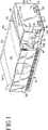
ここで流体処理モジュール28を参照すると、図1〜3に示されるように、流体処理モジュール28は前面ドア36を備え、これは以下により詳細に記載されるように、開かれた場合に、流体処理チャンバ内への生物学的流体の導入および取り出しを可能にする。流体処理モジュール28の前面パネル17はまた、開かれて流体処理モジュールの内部へのより完全なアクセスを可能にする。図3に示されるように、パネル17は留め具17aを備え、これは回転すると、前面パネル17を開いたり取り外したりすることを可能にする。
【0027】
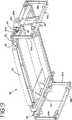
図4〜5は、一般的に、少なくとも頂部パネル14および前面パネル17が取り外された状態の流体処理モジュール28の内部を示す。図5において最もよく理解されるように、流体処理モジュール28は、流体処理チャンバ40を部分的に規定する内部枠組み38、ならびに光源を収納するための光チャンバ42および44(以下により詳細に記載される)を備える。枠組み38は、代表的には、図13に一般的に示されるようにライトボックス10が1つ以上のさらなるライトボックスを支えることを可能にする、任意の頑丈な材料で構成され得る。好ましい材料はアルミニウムであり、そして特にT−6まで強化されたアルミニウム6061である。
【0028】
図5を参照すると、光チャンバ42および44は、流体処理チャンバ40の上下に位置づけられて、生物学的流体の両側からの照射を提供する。当然、ライトボックス10は、流体処理チャンバに近接して配置された単一の光チャンバ、または「頂部および底部」の位置以外で流体処理チャンバの周りに配置された2つ以上の光チャンバを備え得ることが理解される。
【0029】
図3〜5に示されるように、流体処理チャンバ40は、流体保持引出し50を受けるように適応される。光チャンバ42および44は、光引出し60および70を受けるように適応される。流体処理モジュール28はさらに、例えば、図5に示される容器マーカーアセンブリ74を備え得る。以下により詳細に考察されるように、マーカーアセンブリ74は、処理の前および/または後で容器をマークするための1つ以上のマーカー76a〜76dを有し得る。
【0030】
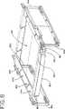
流体保持引出し50の記載をより詳細に参照すると、図13に示されるように、流体保持引出し50は、流体処理チャンバ40への生物学的流体の導入を可能にする。流体保持引出し50は、手動または自動のいずれかで、流体処理チャンバ40の中および外へ移動可能であり得る。流体保持引出し50の手動移動が必要である場合、引出し40はハンドル80を備え得る。1つの実施形態においては、流体保持引出し50の移動は、引出し50の片側または両側のいずれかにあるスライド82によって円滑にされ、このスライド82は、図8、9および13において最もよく理解されるように、枠組み38のレール86内に配置される。あるいは、流体保持引出し50は、ローラーまたは引出し50の流体処理チャンバ40の中および外への移動を可能にする他のデバイスを備え得る。
【0031】
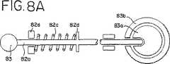
生物学的流体の容器の取り付けおよび取り外しを容易にするために、流体保持引出し50は、好ましくは、引出しが十分に引き出された場合に下向きに傾くことを可能にする旋回台を備える。引出し50の下向きに傾く能力は、図13に示されるように2つ以上のライトボックスがお互いの頂部に積み重ねられた場合に、上側にあるライトボックス内に流体の容器を取り付けるために特に有用であり得る。1つの実施形態においては、流体保持引出し50は、枠組み38に蝶番で取り付けられ得、その結果、流体保持引出し50が十分に開いてハウジング12の外側に出る場合に、引出し50の前端が、例えば54°の角度で下向きに傾き得る。流体保持引出し50が傾くことを可能にするために、ライトボックス10は、チルトノブ83に取り付けられたバネを備え、このバネは、引っ張られた場合に流体保持引出し50を解放して、流体保持引出し50が上記の様式で傾くことを可能にする。より詳細には、図8Aに示されるように、チルトノブ83は、スライド82(図9)に取り付けられた棒82aに接続される。棒82aの端部は、引出し50に取り付けられたリング83bに接続される旋回部材83aに連結される。棒82aはさらに、バネ82cおよびバネ止め82dを備える。棒82aの端部が旋回部材83aに連結された場合、(図8Aに示されるように)リング83bの移動が妨げられる。しかし、ノブ83が引っ張られる場合、(図8Bに示されるように)棒82aは旋回部材83aに連結されず、リングが旋回部材83aに関して回転することを可能にし、それによって、図13に示されるように引出し50が下向きに傾くことを可能にする。
【0032】
図8〜9に示されるように、流体保持引出し50は、一般的には開いていて、図7に示される容器保持トレイ90の配置を可能にするための中央キャビティ88を有する。容器保持トレイ90は流体保持引出し50と一体であり得るが、取り外し可能な一体となっていないトレイ90もまた、より容易な容器の取り付けおよび/またはトレイの掃除のために好ましくあり得る。
【0033】
生物学的流体の処理の間、流体保持引出し50内の流体は、連続的または周期的に攪拌されて生物学的流体の混合を提供し、そして実質的にすべての生物学的流体が、光および/または任意の光化学薬剤に十分かつ均一に曝されることを確実にすることが所望され得る。従って、流体保持引出し50には、生物学的流体を攪拌するための手段が取り付けられ得る。
【0034】
図9および10に示されるように、流体保持引出し50は、例えば、トレイ90の横方向への振動を提供する攪拌アセンブリを備え得る。攪拌アセンブリは、光チャンバ内を前後に延びる一対の固定された下部レール95bを備え得る。上部レール95aは、旋回するように取り付けられたリンクアーム93aおよび93bによって下部レールに取り付けられる。リンクアームは、上部レール95aの横方向の動きを可能にする。振動を提供するために、電気モーター92下部レール95bに取り付けられる。モーター92は、カム97aを回転させる。カム97aは、ローラー97に取り付けられたL型のクランクまたはブラケットであり得る。ローラー97は、上部レール95aから垂れ下がっている平行な壁97bの間に取り込まれる。クランク97aは、ローラー97をモーター92の軸の周りで周回させるので、ローラーは、壁97bの間を前後および上下にスライドし、上部レール95aに横方向の運動を与える。
【0035】
ライトボックス10は、好ましくは流体処理チャンバの上下に配置された、1つ以上の光源を備え得る。保守性(例えば、ランプ交換)の容易さのために、光源は容易にアクセス可能であることが好ましい。本明細書中で使用される場合、「容易にアクセス可能」は、光源へのアクセスが、例えば、スクリュードライバーまたは他の道具の使用なしで、迅速かつ容易であり得ることを意味する。例えば、1つの実施形態においては、光源は、ハウジング12および/または流体処理モジュール28から部分的に取り外されるかまたは完全に取り外されるかのいずれかであることが所望され得る。光源は、前面パネル、側面パネル、頂部パネル、底部パネルのいずれか1つを通してアクセス可能であり得る。1つの実施形態においては、光源は、光引出し60および70内に収納される。図5に示されるように、前面パネル17および/またはドア36が取り外されるかまたは開かれた場合、光引出しは、流体処理モジュール28の中および外へ移動可能であり得る(または、完全に取り除かれさえし得る)。光引出し60および70は、引出し60および70の底面に取り付けられたスライド99(図6)を備え得る。スライド99は、図5に示されるように、ブラケット96および枠組み38のスライド取付けブロック98の上に載って移動する。光引出し60および70はまた、挿入および取り外しの間の把持のためのハンドル84を備え得る。
【0036】
図6に示されるように、光引出し60および/または光引出し70は、仕切り壁102によって分離された2つ以上のチャンバ101および103に分配される。仕切り壁102は、一方の光チャンバの照射からの他方の光チャンバへの光を最小化する。これは、各ランプまたはランプアレイから放出される光および接触している生物学的流体が実質的に一定であることを確実にする。さらに、光チャンバ101および103内の各光アレイは、制御モジュール26により別々にモニターおよび制御され得る。従って、ランプの1つのアレイが切られた場合でも、他のランプのアレイは点いたままであり得る。以下により詳細に記載されるように、このことは、異なるレベルの処理を必要とする生物学的流体の2つ以上の容器が処理されている場合に特に有用であり得る。
【0037】
光引出し60または70の光チャンバ101および103の各々は、一般的に、4枚の側壁105a〜dおよび底壁107によって規定される。壁105a〜dおよび107は、生物学的流体に送達される光の量を最大にするために、反射材料から作製され得るかまたは反射材料でコートされ得る。1つの特定の実施形態においては、光源が紫外A(UVA)の範囲の光を提供する場合、壁105a〜dおよび107は、UVA光の実質的な反射を提供するために、高反射性のアルミニウムから作製され得る。このような材料は、1500G−2の商品名で販売され、ALANOD(Ennepetal,Germany)から入手可能である。
【0038】
本発明における使用のために適切な光源は、特定の生物学的流体を処理するための特定の波長および強度の光を提供し得る任意の光源を備え得る。例えば、白色光、赤色光、赤外光、紫外A光および/または紫外B光を提供し得る光源が使用され得る。光引出し60および70は、単一のランプまたは複数のランプのアレイ100を備え得る。1つの実施形態においては、光源は、UVA(紫外A)の範囲の波長の光を提供し得る標準的な蛍光ランプまたは蛍光電球を備え得る。このようなランプは、製品コードBL352のもとで日本のSagyo Denkaiから入手され得る。光引出し60および70は、ランプ100(より詳細には、ランプフィラメントまたはその近くにあるランプ100の端部)を冷却するためのファン109をさらに備える。
【0039】
図6に示されるように、ランプ100の端部は、ソケットパネル106に収納されるソケット104に挿入される。ソケットパネルはまた、プリント回路基板として役立ち得る。ソケットパネル106は、蝶番で動いて開くことができ、ランプ100への容易なアクセス、ランプ100の容易な挿入および取り外し、および一般的には、光引出し60および70のより容易な保守性を可能にし得る。
【0040】
図5に示されるように、流体処理チャンバ40の一部(詳細には、流体保持引出し50)は、ガラス板110によって光引出し60および70から分離している。図5に示されるように、上部ガラス板110は、枠組み38に載っており、そして一般的には、クランプ112および114によってその場に保持される。流体保持引出し50の一部を下部光引出し70から分離する下部ガラス板110もまた含まれ得る。ガラス板110は、生物学的流体の処理のために使用される波長の光に対して実質的に半透明である。好ましくは、ガラス板110はまた、不必要な光をフィルターにかけ得る。あるいは、分離フィルターが光源と流体処理チャンバ40との間に配置するために提供され得る。1つの特定の実施形態においては、UVA光を用いる生物学的流体の処理が所望される場合、ガラス板110は320〜400nmの範囲内の紫外光に対しては実質的に半透明であり得るが、約320nm未満の波長の光に対しては半透明ではない。このようなガラス板は、製品名B−270のもとでSchott Glass(Yonkers,New York)から市販されている。
【0041】
上記のように、流体処理モジュール28はさらに、マーカーアセンブリ74を備える。マーカーアセンブリ74は、流体処理チャンバ内の容器をマークするための1つ以上のマーカー76a〜76dを備え得る。1つ以上のマーカー76は、処理の異なる段階にある容器をマークするために提供され得る。米国特許第5,557,098号(これは、参考として援用される)に記載されるように、マーカー76a〜76dは、容器の一部(例えば、例えば、容器のフラップ)に穴をあけるためのパンチであり得る。あるいはより好ましくは、マーカーは、容器の指定された部分にインクでスタンプを押すスタンパーであり得る。このようなマーカーは、商品名Printy4911のもとでTrodat(Wels,Austria)から市販されている。
【0042】
図11に示されるように、マーカーアセンブリ74は、光処理の異なる段階の間に複数の容器をマークするための複数のマーカー76a〜dを備え得る。マーカー76a〜dは、スライド114を備えるブラケット78に取り付けられ得る。スライド114は、トラック116からぶら下がっており、トラック116内を移動可能である。トラック116は、ライトボックス10の内部枠組み38に取り付けられる。従って図5に示されるように、アセンブリ74全体は、インク交換、マーカー76の交換のためまたは一般的な修理のために流体処理モジュール28から引き出され得る。
【0043】
図12に示されるように、各それぞれのマーカーユニットは、ギア122、ギア124、リードスクリュー128、リードナット126、ブラケット130およびバネ132を介して、マーカー76を上下に動かす。ギア122および124の動作は、リードスクリュー128の動作を開始させ、そしてリードナット126、ブラケット130および結果的にマーカー76の下向きおよび/または上向きの動作を生じる。
【0044】
流体処理モジュール28は送風機134を備え、これは、流体処理チャンバ40および流体容器内に気流を提供し、それによって流体処理チャンバ40の温度制御を提供する(図5)。送風機134は、送風機134の下に位置する底壁16の開口を介して周囲の空気を受け取る。流体処理チャンバ40に空気を提供することに加えて、送風機134からの空気はまた、例えば図2および4で理解されるように、流体処理モジュール28の開口136および制御モジュール26の穿孔または開口136aを通過し得る。
【0045】
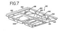
流体処理モジュール28、より詳細には流体保持引出し50を参照して、図5および13に示されるように、流体保持引出し50は、生物学的流体の1つ以上の容器を保持するためのトレイ90を備え得る。図7に示されるように、トレイ90は、流体保持引出し50のキャビティ88内に配置され得る(図8)。1つの実施形態においては、トレイ90は成形プラスチック材料から作製され得る。生物学的流体が2つの側面から処理される場合、成形プラスチック材料はランプ100によって提供される光に対して十分に半透明であるべきである。トレイ90のための適切な材料としては、アクリルポリマー(例えば、ポリメタクリル酸メチル(PMMA))またはポリオレフィンファミリーのメンバー(例えば、メチルペンテンコポリマー)が挙げられる。このような材料は多くの供給元から入手可能であり、CYRO Industries(Rockaway,New Jersey)の商品名ACRYLITE(登録商標)OP4またはMitsui Plastics(White Plains,New York)の商品名TPXが挙げられる。
【0046】
1つ以上の容器が処理される場合、トレイ90は仕切り壁184によって分離される第1の部分180および第2の部分182に分割され得る。図7に示されるように、トレイ90は、生物学的流体容器206のスリットまたは他の開口部をタブ186の上に配置して、トレイ90内の容器の動作を制限し、そして容器が光源によって提供される光の場の中に実質的にあることを確実にするための固定タブ186を備え得る。トレイ90の容積は、少なくとも容器内に含まれる生物学的流体の容積全体を保持するために十分であるべきであり、その結果、攪拌の間でさえも、容器が漏れた場合に液体が溢れてライトボックス10の電気的構成要素および機械的構成要素と接触するリスクを最小化する。
【0047】
生物学的容器が一体となった流体加工セットの一部である場合、トレイ90は区切られて、片方は容器が処理を受けるため、そしてもう片方は残りの使い捨て加工セットのまたは残りの使い捨て加工セットの一部のための、別々の隔室を提供し得る。例えば、図7に示されるように、第1の部分180および第2の部分182はそれぞれ、非連続的な壁192によって分離される第1の隔室188および第2の隔室190を備える。第1の隔室188は、生物学的流体の容器206を保持し得、第2の隔室は流体加工セットの残りの構成要素を保持し得る。壁192のスロットは、容器206を使い捨て加工セットの残りと連結するチューブを収容する。トレイ90またはトレイの第2の隔室190は、容器保持タブまたは釘193をさらに備え、容器を第2の隔室内の適所に保持し、トレイ90内のこのような容器の動きを制限することを補助し得る。
【0048】
使い捨て加工セットを有するトレイ90が流体処理チャンバ50に導入される場合、第1の隔室188内の容器206は、光源によって提供される光の場の中に実質的に位置づけられる。使い捨て加工セットの残りおよび/または第二の隔室190内の容器は、図4および5に示されるように、マーカーアセンブリ74と実質的に並んでいる。従って、処理の状態は、マーカー76a〜dによって第2の隔室190内にある加工セットの他の容器に示され得る。
【0049】
ライトボックス10は、前処理および処理プロセスの間の異なる状態を検出するためのセンサーを備え得る。センサーは、制御モジュール26内に収納されるライトボックスのマイクロプロセッサへ信号を中継する。例えば、図14に示されるように、センサー(例えば、404,430)は、センサー入力/出力ボード170を通して信号を送り、このボードはその信号をマイクロプロセッサ160によって認識可能なフォーマットに変換する。コンピュータは、警報音またはディスプレイスクリーン37上のメッセージのいずれかによって、オペレーターに警告する。オペレーターは、警報またはメッセージに応答して、キーパッド39を介して行動をとる。あるいは、特定の警告状態に応答して、制御システムは必要な場合には自動的に行動(例えば、処理の終了)をとるように前もってプログラムされ得る。
【0050】
例えば、ライトボックス10は、ランプ100によって流体処理チャンバ50に提供される光の強度を測定するための内部光強度センサー404を備え得る。ランプ100によって提供される光の強度が所望の処理のために十分ではない場合、センサー404は、上記のように入力/出力ボード170(図14)を介して信号をマイクロプロセッサ160に送る。
【0051】
1つの実施形態においては、光強度センサー404は、光引出し60および70の光チャンバ101および103(図6)の中に配置され得る。1つの実施形態においては、光引出し60および/または光引出し70は、光強度センサーサブアセンブリ402を引出し60および/または引出し70の裏側に備える。図6aに示されるように、サブアセンブリ402は、サブアセンブリ402に取り付けられ、引出し60および/または引出し70の底壁107に配置されるセンサーウインドウ406内に配置される2つ以上のセンサー404を備える。センサーウインドウ406は、ランプ100からの光が通過し、センサー404と接触することを可能にする。センサー404は、1つ以上のフィルターを備えるかまたは1つ以上のフィルターと共に使用されて、不必要な光をフィルター除去し得る。より詳細には、ライトボックス10が光化学薬剤を活性化するために使用される場合、センサー404と共に使用されるフルターは、特定の光化学薬剤が最も効果的に活性化される範囲の波長(すなわち、アクションカーブ)と実質的に一致する波長の範囲内で、最大の感度を有することが所望され得る。このことは、センサー404が光化学活性化の有効性を検出することを可能にする。このようなセンサーは、製品コードTSL230Bのもとで、Texas Advanced Optoelectronics Solutionsから入手可能である。フィルターは、種々の供給元(例えば、Schott Technical Glass(Duryea,Pennsylvania))から入手可能である。
【0052】
流体保持引出しセンサー144は、流体処理チャンバ40内の流体保持引出しの位置をモニターするために備えられ得る。流体保持引出し位置センサー144は、引出し50が完全に閉じた位置にあり、従って生物学的流体の容器がランプ100によって提供される光の場の中に実質的にあることを確実にする。引出しが完全に閉じた位置にない場合、センサー144はマイクロプロセッサに信号を送り、オペレーターに警告し、そして処理が進行することを防ぐ。
【0053】
ライトボックス10は、直接的または間接的のいずれかで、流体処理チャンバ40内の温度をモニターおよび測定するための温度センサー145をさらに備え得る。温度センサーは、流体処理チャンバ40内に配置され得るか、または図4および5に示されるように、ライトボックス10の外部に配置されて外側の環境の周囲温度を測定し得る。例えば、周囲温度センサー145は、ライトボックス10の表面のいずれかに配置され得る。1つの実施形態においては、図1および2に示されるように、周囲温度センサー145は制御モジュール26またはその近くに配置される。周囲温度センサー145は、送風機134によって流体処理チャンバに送達されている空気の温度を示す。温度が予め決められた温度範囲から外れた場合、周囲温度センサーは上記で一般的に記載されたようにマイクロプロセッサに信号を送る。この信号は、温度がその限界に近づいているか、またはその限界を超えたことをオペレーターに警告する。従って、オペレーターおよび/または機器は、さらなる行動をとり得る。
【0054】
攪拌アセンブリによって提供される攪拌をモニターするためのセンサーを含む、さらなるセンサーが提供され得る。センサー430は、図11Aに示されるようにマーカーアセンブリ74に取り付けられ得、上記の攪拌アセンブリの動作を測定する。1つの実施形態においては、センサー430は、赤外光源(例えば、発光ダイオード(LED)またはレーザーがあるが、これらに限定されない)を備え得、これは攪拌アセンブリの選択された反射部分と接触する。センサー430が反射を検出しないかまたは予め決められた振動数の反射を検出しない場合、従ってそれはマイクロプロセッサに信号を送る。
【0055】
ライトボックス10はまた、ライトボックスの前面ドアが処理の間閉じているか否かを検出するセンサー440を備え得る。ドアセンサーは、図3に示されるドア36と磁石プレート441との間の接触を検出する磁気スイッチであり得る。また、プランジャースイッチ36a(図4)は、ドア36が閉じている場合に押される。ドア36が開いている場合、プランジャースイッチ36aは、電気の遮断として役立つ。ドアが開いている場合、このシステムは処理を進行させない。
【0056】
ライトボックス10はまた、容器がマーカー76によってマークされるための位置にあるか否かを決定するためのセンサー450を備え得る。図11Aに示されるように、センサー450はマーカー76に取り付けられ得、そして代表的には流体保持トレイ90の下に位置する発光ダイオード(LED)(示されない)と並んでいる光レシーバを備え得る。容器のラベルは、トレイ90の第2の隔室190の中に配置されて、光レシーバー450がLED信号を受け取ることを防ぎ、容器の存在を示す。逆に、センサー450が信号を受け取る場合、このことは、容器が存在せず、そしてマーカーが起動しないことを示す。さらに、各マーカー76a〜dは、マーカーの移動が起こったか否かを検出し、そしてマーカーを構成する部品に対する機械的故障または損傷を防ぐためのマイクロスイッチ(図14で470として示される)を備え得る。
【0057】
さらに、ライトボックス10によって提供される光の強度を検査するためおよびライトボックス10の較正のための、ポータブルかつ取り付け可能な、光強度を検出する検査および較正デバイスまたはラジオメーター460が提供され得る。ラジオメーター460は、生物学的流体に送達されるエネルギー線量を測定するために、流体処理チャンバ内に配置されるように適応され得る。より詳細には、ラジオメーター460は、流体容器保持トレイ90の中に配置されるように適応され得る。1つの実施形態においては、ラジオメーター460は、トレイ90の隔室(例えば、トレイ90の第1の隔室188)内に配置されるように適応され得る。
【0058】
図14Aに示されるように、ラジオメーター460は、上面467および底面468を有する支持体465を備え得る。支持体465は、代表的にはプリント回路基板である。1つ以上のセンサー469は、電気的および物理的に支持体465に接続される。
【0059】
光源は常に均一に発光するわけではないことは公知である。例えば、ランプの使用期間に依存して、ランプの一部分から発する光の強度は、ランプの別の部分から発する光の強度と同じであるわけではない。従って、好ましい実施形態においては、図14Aに示されるように、ラジオメーター460は、上面および/または底面にわたって間隔をあけて配置された複数のセンサーを備え、1つ以上のランプの異なる点からの光を受け取り得る。また、センサー469は、支持体465の片面に配置され得るが、好ましくは上面467および底面468の両方に配置される。センサー469の上下の配置は、ラジオメーター460が(ライトボックス10の1つの実施形態におけるように)2つの向かい合った光源によって提供される光を測定するために使用される場合に、特に好ましい。
【0060】
電気コード(示されない)は、ライトボックス10(例えば、ポート461(図5))への電気的接続のために、ラジオメーター460に取り付けられる。このことは、ラジオメーター460がライトボックス10のコンピュータに基づく制御システムにデータを伝達することを可能にし、このシステムは、伝達されたデータに基づいて、オペレーターに情報を提供し、そして/または自動的に行動をとる。ラジオメーター460はまた、ライトボックス10のトレイ90内のタブ186上に配置するためのスリット472を備え得る。
【0061】
センサー469は、代表的には選択された波長の光を検出し得る光ダイオードであり得る。センサー469はまた、実質的に上記に記載されたように、望ましくない光をフィルター除去するためのフィルターを備え得るか、またはフィルタ0と共に使用され得る。
【0062】
ライトボックス10と共に使用される場合、ラジオメーター460の寸法は、ライトボックス10と共に使用される、流体が充填された容器の寸法と実質的に等しいことが好ましい。従って、ラジオメーター460の光検出領域は、このような充填された容器と実質的に等しい高さ、幅および厚さを有することが好ましい。流体が充填された容器と実質的に等しい寸法を有するラジオメーターは、流体に送達されているエネルギーおよび処理の有効性の信頼のおける近似を提供する。
【0063】
上記のように、ラジオメーター460は、例えばオペレーターによる光強度検査および一般的にはライトボックス10およびより詳細には、内部センサー404の較正のために使用され得る。光強度検査のためにラジオメーター460を用いる方法に従って、オペレーターは、トレイ90の第1の隔室内にラジオメーター460を配置し得る。コードは、ライトボックス10内の歪み解放タブ474に押し込まれ得る(図8)。流体保持引出し50は流体処理チャンバ40に挿入され、そしてドア36は閉められる。ランプ10は点灯され、そして送達された光はセンサー469によって測定される。詳細には、センサー469によって測定された光は、システムのマイクロプロセッサによって処理され、流体処理チャンバ40に提供されているエネルギーの示度を提供する。オペレーターは、ランプ100の出力をモニターし得、そしてその示度を予め設定された受容可能なエネルギー線量の範囲と比較することによって、ランプの出力における任意の減少を決定し得る。さらに、センサー469によって提供された示度はまた、センサー404によって提供された示度と比較され、センサー404の任意の減少した検出能力を検出する。
【0064】
従って、例えば、ラジオメーター460によって測定されたエネルギー線量が、センサー404によって検出されたエネルギー線量と実質的に等しいが、予め設定された線量範囲外にある場合、このことはランプ100の出力が減少し、そしてランプ100は交換されなければならないであろうということが示され得る。あるいは、ラジオメーター460によって測定されたエネルギー線量が、機器の予め設定された予想された線量と実質的に等しいが、いずれもセンサー404によって測定されたエネルギー線量と異なる場合、このことはセンサー404の検出能力が減少したことを示し得る。最後に、センサー404によって測定された線量が、予め設定された予想された線量と実質的に等しいが、ラジオメーター460によって測定されたエネルギー線量と異なる場合、このことはラジオメーター検出能力が減少したことを示し得る。ラジオメーターはまた、ライトボックス10を較正するために使用され得る。ラジオメーター460は、標準(例えば、National Institute for Standards and Technology(すなわち、NIST)による標準)に対してそれ自身較正され得る。
【0065】
当然、ラジオメーター460は他の適応における用途を有し得、そして本発明の装置または方法における使用に限定されないことは理解される。実際に、ラジオメーター460は、拡張された表面領域にわたって光が測定されるべき場合はいつでも使用され得る。
【0066】
攪拌アセンブリ、光源、送風機、マーカーアセンブリを含む流体処理モジュール28の構成要素は、図14に示される電源によって電力を供給される。(図14において、文字「n」は、電気的構成要素または機械的構成要素(例えば、センサー、ランプ、バラストなど)を表す)。例えば、ランプ100に電力を共有するための電源(バラスト)166は、中継ボードおよび絶縁変圧器29を通る。振とうモーター92は、中継ボードおよび絶縁変圧器29を介して電力が供給される。さらなる電源168は、送風機134、光引出しファン101、およびマーカー76a〜dおよびドアロック480のための駆動モーター120に電力を供給する。好ましくは、これらの構成要素に電力を供給するための電源は、約24ボルトDCであり得る。電源167は、+5、+12、−12ボルトDCを、例えばコンピュータボード160に供給し得る。
【0067】
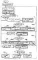
最後に、ライトボックス10は、ライトボックスの操作を制御するために、プログラム可能なコンピュータソフトウエアに基づく制御システムを備える。この制御システムは、図19〜23に一般的かつ概略的に示され、そして生物学的流体を加工および処理する方法の説明と共により詳細に記載され、この説明は以下に提供される使い捨て加工セットの説明の後に記載される。
【0068】
(b.使い捨て加工セット)
ライトボックス10と共に有用な使い捨て加工セットは、図15〜18に示される。代表的に、使い捨て加工セットは、プラスチックチューブによって一体的に接続された2つ以上のプラスチック容器を備える。少なくとも1つの容器は、光処理の間に生物学的流体を保持するために適しているべきである。他の容器は、処理後の生物学的流体を保存するために適しているべきである。以下により詳細に記載されるように、使い捨て加工セットは、生物学的流体の容器に結合され得、そして流体は使い捨て加工セットの容器に移され得る。
【0069】
使い捨て流体加工セット200の1つの実施形態が図15に示される。処理セット200は、容器202、容器206、容器210および容器214を備える。これらの容器は、以下に一般的に示されそして詳細に記載されるようなチューブセグメントで一体的に相互接続される。容器202、206、210および214の内部容積は、処理されている生物学的流体に依存して変化し得る。非限定的な例においては、容器202は約15〜30ml、容器206および210は約1000ml、そして容器214は約1000〜1500mlの間の流体を保持し得る。当然、他の所望の大きさおよび容積が使用され得、それらは本発明の範囲内である。
【0070】
使い捨て加工セットが病原体不活化処理において、またはその一部として使用される場合、容器202は、例えば、生物学的流体と混合される光化学薬剤を含有し得る。このような光化学薬剤の例としては、米国特許第5,709,991号に記載されるソラレン化合物およびフェノチアジン色素のファミリーの化合物(例えば、メチレンブルーがあるがこれに限定されない)が挙げられる。容器202は、このような光化学薬剤を保持するために適切な任意の材料から作製され得る。1つのこのような材料は、エチレンポリプロピレン、ポリアミド、およびポリスチレンの末端ブロックを有するエチレンとブチレンとのブロックコポリマーのブレンドであり得る。このような材料から作製される容器は、PL2411の商品名のもとでBaxter Healthcare Corporationから入手可能である。容器202は、その容器から延びていて、封着された端部204を有するチューブセグメント203を備える。容器202から延びている第2のチューブ205は、容器206と一体的に接続される。別の実施形態においては、光化学薬剤は容器206に収納され得るかまたは予め配置され、それによって光化学薬剤を保持するための別の容器202の必要性を排除する。なお別の実施形態においては、光化学薬剤は、使い捨て加工セットと併合される前に生物学的流体と合わされ得る。例えば、光化学薬剤は、ドナーから集められた生物学的流体を保持するために使用される容器201(図17)に含まれ得る。
【0071】
容器206は、好ましくは光処理の間に生物学的流体を保持するために適した容器である。従って、容器206は、選択された波長の光に対して半透明であり、そして公知の滅菌形態(蒸気滅菌、ガンマ線照射および電子線照射を含む)によって滅菌可能である、透明な、耐久性のある熱可塑性材料から作製されることが望ましい。例えば、処理されるべき血液生成物が血小板または血漿を含み、かつその処理がUVA範囲の光を用いるべきである場合、容器は、UVA光に対して実質的に半透明であり、かつ滅菌後も安定なままである材料から作製される。このような材料としては、ポリ塩化ビニルが挙げられ得るが、より好ましくは、熱可塑性ポリマーおよびコポリマーのブレンド(汎用ポリマー、エラストマーなどを含む)であり得る。1つのこのような材料としては、エチレンとブチレンとの中央ブロックおよびポリスチレンの末端ブロックを含む上記のブロックコポリマーが挙げられる。上記の型のブロックコポリマーは、KRATONの商品名のもとでShell Chemical Companyから入手可能である。ブロックコポリマーは、他のポリマー(例えば、超低密度ポリエチレン(ULDPE)およびエチレン酢酸ビニル(EVA))とブレンドされ得る。ブレンド材料から作製された容器は、PL−2410の商品名のもとで、Baxter Healthcare Corporation(Deerfield,Illinois)から入手可能である。他の熱可塑性材料はまた、容器206のために適切であり得、KRATON、EVA、およびポリプロピレンを含む材料が挙げられる。このような材料から作製された容器はまた、PL−732の商品名のもとでBaxter Healthcare Corporationから入手可能である。容器206のためのなお他の適切な材料としては、フルオロポリマー(例えば、ポリテトラフルオロエチレン(PTFE)、PFA、またはこのようなフルオロポリマーを含むコポリマーが挙げられる。
【0072】
容器206はさらにスリット207を備え、これは上記のように、トレイ90の固定タブ186の上に配置され得る。容器206は、チューブセグメント208を備え、これは、容器210と一体的に接続され得る。
【0073】
生物学的流体の病原体不活化においては、容器210は、例えば過剰な光化学薬剤または光活性化プロセスの副生成物を除去するための吸着材料211を含み得る。吸着材料は、好ましくは容器210の内部チャンバ内の容器の壁またはその一部に固定された、半透過性の袋に含まれ得る。容器210の内部チャンバは、容器206からの生物学的流体を保持するために十分な容積を有する。このような容器および吸着材料は、「Plastic Containers Having Inner Pouches and Methods for Making Such Containers」と題された同時係属中の特許出願(これは、Mahmood Mohiuddin、George D.CiminoおよびDerek J.Heiの名義で本出願と同時に出願され、そしてその全体が参考として援用される)により詳細に開示される。上記のPL−2410容器およびPL−732容器において使用されるような材料は、容器210における使用のために適切である。
【0074】
容器210はまた、時間感応性のテープ209を備え得る。テープ209は、時間と共に色が変化し、従って生物学的流体が十分な時間の間吸着材料と接触したか否かをオペレーターに知らせる。容器210は、チューブセグメント211によって別の容器214に一体的に接続され得、この容器214は生物学的流体の保存のために適している。図15に示されるように、容器210の内部と連通しているチューブセグメント211の部分は、吸着剤の遊離している粒子(それがある場合)を捕捉するためのフィルター211aを備え得る。
【0075】
容器214は、ラベル216を備え得、そして/またはラベル216を受容し得る。このラベル216は、バーコード222、または生物学的流体に関する情報を提供する他の印を有し得る。例えば、バーコード222は、ドナー、製品、生物学的流体のロット番号、有効期限などを識別し得る。容器214は、流体処理の状態または進行に関する情報を提供するために使用されるさらなるバーコードまたは印224(以下により詳細に記載される)を備え得る。容器214はまた、トレイ90の対応する釘(193)に配置するためのスリット226および/または開口部228、230を備え得る。上記のような材料は、容器214において使用するために適している。容器214はまた、当業者によって認識されるように、サンプリング袋214a、および後の輸液の間の流体のアクセスを可能にするためのアクセスポート214bを備え得る。
【0076】
代替の実施形態においては、使い捨て加工セットは、容器210の吸着材料を収納し、そして生物学的流体を保存するための単一の容器を備え得、それによって上記の容器210および214の機能を組み合わせる。
【0077】
本明細書中に記載される使い捨て加工セット200は、図15に示されるように、チューブセグメントに配置される破断可能な部材230(a〜c)をさらに備え得る。破断可能な部材230は、適切な時間に破断されて加工セット200の容器の間の流体連絡を確立する。このような破断可能なコネクタは、米国特許第4,294,297号(これは、本明細書中に参考として援用される)に詳細に記載される。使い捨て加工セット200のチューブセグメントは、トレイ90内の使い捨て加工セットの適切な位置を示すため(以下により詳細に記載されるように)および/またはチューブが切断されそして封着されるべき場所の指標として役立つための、指標234aおよび234bをチューブ上にさらに備え得る。1つの実施形態においては、指標234は、チューブセグメントの周りに配置されるプラスチックリングであり得る。当然、他のチューブ指標手段も使用され得る。
【0078】
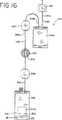
流体加工セットの別の実施形態は、図16に示される。図16において、使い捨て加工セット240はまた、光化学薬剤を有する容器242、光処理の間に生物学的流体を保持する容器244、過剰な光化学薬剤および/または光活性化プロセスの副生成物を取り除くための吸着材料を含む容器246、ならびに生物学的流体の保存のために適切な容器248を備える。容器248は、バーコードまたは他の印を有するラベル249を受容するように適応され、そしてさらなる印251(例えば、実質的に上記に記載されたようなさらなるバーコードを含む)を備え得る。
【0079】
先に記載された実施形態の容器210とは対照的に、容器246は、吸着材料212を含むが、任意の有意な時間の間に生物学的流体を保持するためのチャンバを有さない貫流デバイスである。このような貫流デバイスは、国際公開WO96/40857(これは、本明細書中に参考として援用される)に記載される。使い捨て加工セット240は、空気リザーバ256および空気シンク258をさらに備え得る。空気リザーバ256は、容器244からの生物学的流体の追い出しを補助するための空気を提供し、そして空気シンク258は、処理の後に保存容器258から追い出された過剰な空気を受け取る。空気リザーバ256および空気シンク258は、任意の適切な生体適合性材料(上記の材料を含む)から作製され得る。同様に、使い捨て加工セット240の容器もまた、上記で一般的に記載された材料から作製され得る。好ましくは、容器256は、実質的に空気を透過しない。
【0080】
図15の実施形態のように、図16に示される使い捨て加工セット240の容器は、チューブセグメント243、245および247によって一体的に相互接続され得る。チューブセグメントは、容器間の流体連絡を開放するための破断可能な部材249(a〜c)をさらに備え得る。
【0081】
使い捨て加工セット200(または240)は、代表的には、ユーザーが開封および使用することが容易な様式で封着された包装で、ユーザーに提供される。例えば、包装を開封する際、流体加工において最初に使用されるべき容器は、包装の最上部近くに位置されることが好ましい。例えば、図15に示される加工セット200においては、容器202は、包装の最上部近くに位置され、続いて、容器206、続いて容器210および214を含む使い捨て加工セットの残りが位置される。さらに、使い捨て加工セットが容器202(または図16の実施形態においては242)を備える場合、少なくともこのような容器は、内容物(すなわち、光化学薬剤)が光化学薬剤の早期の活性化を生じ得る光に曝されることを防ぐための、別のさらなる光不透過性の上包みを備えるべきである。1つの実施形態においては、光不透過性の上包みは、容器202の外壁に持続的に封着され得る。
【0082】
好ましい実施形態においては、容器210および214は、ホルダー内に含まれ得るか、またはホルダーによって一緒に保持され得る。ホルダーは、容器210および214を一緒に保持する任意のデバイス(例えば、クランプ)であり得る。ホルダーは、使い捨て加工セットと一体であり得るか、または別々に提供され得る。
【0083】
より好ましくは、ホルダー260(図17〜18に示される)は、レセプタクルまたは他の貝殻様保持デバイスであり得る。1つの実施形態においては、ホルダー260は底壁262を備え得、これは容器210および214を容器206から分離する。好ましい実施形態においては、ホルダー260は、図17〜18に示されるように、側壁262および264、後面壁268を有し得、そして実質的に開いた前面部分を含む。さらに、底壁262は、使い捨て加工セット200の容器を接続するチューブを収容するためのスロット263を備え得る。ホルダー260はまた、使い捨て加工セットの開封の前に容器202のチューブセグメントを保持するためのさらなる側開口265(例えば、図17に示される)を備え得る。ホルダー260は、任意の適切な材料(例えば、プラスチックまたは厚紙があるが、これらに限定されない)から作製され得る。好ましくは、ホルダー260は、滅菌可能かつ耐衝撃性であり得る成形プラスチック材料から作製される。
【0084】
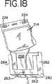
ホルダー260の代替の実施形態は、図18A〜18Dに示される。図18A〜18Cに示されるように、ホルダーは2つの枠または部分的な枠部分600および602を備え得る。図18Bおよび18Cに示されるように、枠部分600および602は結合され得、そして蝶番604を備え得る。あるいは、枠部材600および602は、図18Dに示されるように、完全に分離可能であり得る。枠部分600および602は、枠部分600および602は、これらの枠部分を共に固定するための手段(例えば、示されるような接合スロット605およびピンまたは突起606)を備える。図18A〜18Dに示されるホルダー260は中央開口608を備え、これは、ホルダー260内に配置された容器のラベルが外部の環境に曝されることを可能にし、以下に記載されるように、例えば、バーコードリーダーによってスキャンすることおよび/またはマーカー76によってマークすることを可能にする。
【0085】
1つの実施形態においては、容器210はホルダー260の前面部分に配置され、その結果、図17に示されるように、容器210に適用されるべきラベルおよび容器自体にある他の印が、ホルダー260の開口部分を介して外部の環境に曝される。例示の目的のために、図17〜18において、容器214に適用された場合のラベルが示される。1つの実施形態においては、容器214は使用時にラベルを備え得ず、そしてラベルは生物学的流体の容器から容器214に移され得る。あるいは、容器214はラベルを備え得、そしてさらなるラベルが生物学的流体の容器から移され得る。任意の場合において、容器214は、容器214の後ろに配置される容器210(これもまた折り畳まれる)と一緒に、半分(または三つ折り)に折り畳まれ得る。さらに、折り畳まれた容器214は、その端部で軽くスポット溶着され得、容器を折り畳まれたままに保ち、そして容器の取り扱い性を改善する。溶着は、容器214を折り畳まれた位置に保つために十分に強力であるべきであるが、ユーザーによって適用される過度の力が溶着された端部をはずすために必要とされるほど強力ではない。スポット溶着された容器210の端部は、ユーザーによってゆっくりと引っ張られた場合に離れるべきである。
【0086】
(c.流体を加工および処理する方法)
使い捨て加工セット200(または240)を用いて流体を加工する方法、および例えばライトボックス10において光を用いて生物学的流体を処理する方法が、ここに記載される。以下の記載は、生物学的流体における病原体の引き続く不活化のために生物学的流体を加工することに関連して提供されるが、以下に記載される多くの工程はまた、病原体不活化に関与しない他の流体加工および処理方法において行われ得ることが理解されるべきである。以下の記載は、図15の使い捨て加工セットを例として用いて提供されるが、この記載はまた、他の加工セット(例えば、図16のセット)に適用され得ることが理解される。
【0087】
生物学的流体(例えば、血液)を加工セット200を用いて加工する方法に従って、収集された血液または生物学的流体の容器が提供される。収集の方法は本出願の範囲を超えるが、血液生成物を収集する代表的な方法としては、自動または手動の遠心加工、血液生成物の分離および収集、血液生成物の膜分離など芽挙げられる。遠心血液加工システムの一例は、Baxter Healthcare Corporationによって販売されるAMICUS(登録商標)分離器である。
【0088】
収集方法に関わらず、収集された血液生成物の容器は、代表的には、ドナー、血液生成物およびロット番号を識別する情報を含むラベルを有する。最も代表的には、このような情報は、ラベル上の1つ以上のバーコードの形態で示され、これはバーコードリーダー(例えば、ライトボックス10のバーコードリーダー41)によってスキャンされ得、そして読み取られ得る。このようなラベルは、取り外し可能であり、そして使い捨て加工セット200の容器214に移転可能である。
【0089】
代表的には、収集容器はそこから延びているチューブセグメントを備える。従って、収集容器201からのチューブおよび使い捨て加工セット200からのチューブセグメント203は、図17に一般的に示されるように、滅菌様式で合わされて結合される。チューブ部分の滅菌結合のために有用なデバイスは、日本のTerumo Corporationから入手可能であり、Terumo SCDの商品名のもとで販売される。このデバイスは、2つの向かい合ったチューブ部分を滅菌様式で熱封着する。熱封着による熱は、チューブセグメントの中に侵入し得るかまたはその中に存在し得る外部環境からのいかなる細菌も死滅させ、それによって加工セット全体の無菌性を維持する。当然、無菌性を維持しつつ2つのチューブセグメントを結合するための任意の方法および装置が使用され得る。
【0090】
一旦、チューブセグメントが結合されたら、破断可能な部材230aは破断され、収集容器201から容器206(図15)への開放流路を提供する。容器202からの光化学薬剤はまた、容器206へ流入する。容器206への流体移動後、チューブセグメントは切断および封着され、そして容器202および収集容器201を備えた使い捨て加工セットの部分は廃棄される。指標234aは、チューブが切断されるべき場所に関する参照点を提供する。指標は、容器206に可能な限り近くに配置されることが好ましく、その結果、ほとんどの生物学的流体が、最も混合および処理されそうな容器206内に保持される。
【0091】
使い捨て加工セットをトレイ90へ配置する前または後に、オペレーターは、バーコードリーダー41でラベルおよび他の容器の印をスキャンし得る。主要な容器ラベル216または容器自体のバーコード222は、処理されるべき生物学的流体に関する情報を機器に提供する。このデータに基づいて、光処理機器またはオペレーターは、光の線量を指示し、次いで処理の持続時間を計算する。
【0092】
使い捨て加工セット200の容器206は、代表的にはトレイ90の第1の隔室内に配置される。容器206のスリット207は、第1の隔室188の保持タブ186上に配置され、そしてその中に容器が配置された状態のホルダー260は、トレイ90の第2の隔室190内に配置される。容器216のスリットおよび/または開口部は、同様に第2の隔室190の保持タブまたは釘193上に配置される。容器206を容器210(および/または214)と接続しているチューブは、壁192のスロット内に押し込まれ得る。チューブは、上記の攪拌アセンブリによって提供される横方向の振動の方向と平行に位置づけられることが好ましい。このことは、チューブセグメント208内の任意の流体もまた混合されることをさらに確実にする。指標234bは、チューブの切断のための参照点として役立つだけでなく、実質的に容器全体およびその中の生物学的流体が光の場の中にあることを確実にすることによって容器を配置するための参照点として役立つ。この指標は、スロットの幅よりも大きい直径を有する。
【0093】
一旦、容器がトレイ90のそれぞれの隔室内に入ると、流体保持引出し50は閉じられる。上記のように、プランジャースイッチ36a(図4)は、ドア36が閉じられたときに押される。ドア36が開いている場合、プランジャースイッチ36aは、電気の遮断として役立つ。ドアが開いている場合、このシステムは処理を進行させない。
【0094】
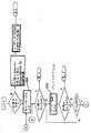
ライトボックス10は、ライトボックス10の操作を制御するためのプログラム可能なコンピュータソフトウエアに基づく制御システムを備える。この制御システムは、図19〜23に一般的かつ概略的に図示される。図19〜23に示されるように、このシステムはライトボックス10の種々の局面および処理操作(例えば、ライトボックス操作の起動段階、容器装着段階、容器処理段階および容器取り外し段階)を試験し、モニターしそして制御する。この制御システムは、スクリーン37上に表示された英数字ユーザインタフェースまたはグラフィカルユーザインタフェースのいずれかを介して、オペレーターが行動をとるかまたはオペレーターに処理状態の通知をすることを可能にする。種々の機能が制御パネルを介してオペレーターによって開始され得るか、または制御システム自体によって自動的に開始され得る。
【0095】
例えば、図19に示されるように、オペレーターが機器を作動させた(工程300)後、制御システムは、ソフトウエア301をロードする工程301、ソフトウエアを初期設定する工程302、ならびにグラフィカルユーザインターフェーススクリーンおよびメニューを表示する工程304を包含する、一連の工程を開始させる。次いでオペレーターは、処理機能306または一般的なユーザー機能308を含む利用可能な一連の機能から選択し得る。あるいは、オペレーターは、システム312を終了させることを選択し得る。診断チェック310もまた、代表的にはサービス技術者によって選択および実行され得る。
【0096】
処理機能306が選択される場合、制御システムは、処理が適切であるか否か、より詳細には、ライトボックス10が図20Aに示されるように処理のために準備されているか否かを、プログラムされたソフトウエアを介して自動的に決定する。従って、例えばこのシステムが、光源の故障またはセンサーもしくは他の機器のうちの1つの故障を検出する場合、処理は可能ではなく、そしてその状態が修理されるまで進行しない。しかし、処理が可能である場合、このシステムはオペレーターにそのオペレーター固有の識別名を入力することを指示し(314)、次いで容器(すなわち、生物学的流体)の情報を入力することを要求する(316)。容器の情報は、手動で、または例えば図15に示される容器214上のバーコード222をスキャンすることによって入力され得る。処理が適切である場合、このシステムは一般的に図20Bに示されるような次の機能または段階に進む。
【0097】
図20Bに示されるように、制御システムはオペレーターが選択するためのさらなるオプションを表示する。例えば、オペレーターは、工程320に示されるように、容器の処理を進行するか、第2の容器の処理を要求するか、または操作全体をキャンセルし得る。「バッグ2」オプションが選択される場合、オペレーターは再び容器の情報を入力することを要求され(322)、そしてシステムは上記に一般的に記載される工程を繰り返す。単一の容器に対する処理が行われるべきである場合、オペレーターは処理機能を選択する(324)(これは図20Bに一般的に示され、そして以下により詳細に記載される)。
【0098】
容器がトレイ90に配置された後、処理を開始するために、システムは図21の工程328に示されるように光源100、振とうモーター92およびファンを活性化する。機器は、オペレーターによる確認のために、処理されるべき流体および処理プロセスに関する情報を一般的に表示し得る。例えば、1つの実施形態においては、330に示されるように、機器は、容器に適用されるべきエネルギーの予め決定された標的線量、選択された処理時間、および処理の間に生物学的流体に適用されている線量パーセントの稼働値を表示し得る。処理は、オペレーターによって終了されるか、または警告状態に応答した機器によって自動的に終了されない限り継続する。
【0099】
1つの実施形態においては、処理の開始時および処理が完了した後に、容器はマーカー76によってマークされる。マーカー76によってつけられたマークは、バーコードを消すかそうでなければマスクし、バーコードを読み込み不可能にする。従って、2つのマスクされたバーコード224を有する容器は、処理が首尾良く完了したことを示す。一方、バーコード224の1つのみがマスクされた場合、これは処理が首尾良く完了せず、そして容器は廃棄されるべきであり得ることの指標として役立つ。マーカー76によるバーコード224のマスキングはまた、処理された容器が再び処理されないことを確実にする。
【0100】
処理の間、システムはエネルギー計算332を行い、これは光強度センサーの示度に予め選択された較正ファクターを乗算し、同じチャンバおよび平面におけるセンサーにわたる示度を平均し、そして同じチャンバ内の平面について受け取った示度を加えることによって計算される。制御システムはさらに、処理状態334を確認する。処理が完了した場合、336に示されるように、このシステムは自動的にランプ100を消灯する。
【0101】
このシステムは、337に示されるように、ランプの寿命についての情報を自動的にアップデートし得、そして容器の記録をアップデートし得る(338)。制御システムは、終了するまで振とうモーター92に電力を供給し続ける。結果は中央コンピュータ502(図14)に伝達され得る。処理後、このシステムはオペレーターに容器を取り外すように促し(342)、そして所望の場合、図20Bの325に示されるように、ユーザーが別の処理を行うことを促し得る。このプロセスは、上記に一般的に記載されるように繰り返され得る。
【0102】
処理時間およびエネルギー線量は、処理されるべき生物学的流体に依存して変化する。例えば、処理時間は少なくとも1分間であり得るが、1分間未満でもあり得る。ライトボックス10のが生物学的流体の病原体不活化のために使用される場合、処理は、代表的には1〜30分間の間のいずれかであり得る。例えば、血小板の病原体不活化に対しては、処理は代表的には1〜10分間の間であるが、より代表的には約3〜4分間である。例えば、血漿の病原体不活化に対しては、処理はまた、好ましくは約3〜4分間である。
【0103】
単位面積当たりのエネルギー(すなわち、エネルギー束)は、単位面積当たりの(または放射束の場合、標的への)電力と曝露時間との積である。従って、標的(例えば、1つの実施形態においては、生物学的流体)へ送達される単位面積当たりのエネルギーの量は、曝露の持続時間および照射量(標的に入射する単位面積当たりの放射電力)とともに変化する。1つの実施形態においては、送達される全放射エネルギー束は、約400〜700nmの間の波長範囲にわたって測定して、約1〜100J/cm2の間であり得る。別の実施形態においては、光源がほぼ紫外範囲の光を提供する場合、生物学的流体に送達される全放射エネルギー束は、約320〜400nmの間の波長範囲にわたって測定して、好ましくは1〜20ジュール/cm2の間であり得る。1つの特定の実施形態においては、血小板または血漿に送達される全放射エネルギー束は、約320〜400nmの間の波長範囲にわたって測定して、約1〜5J/cm2の間であり得、より代表的には約3〜4J/cm2の間であり得る。流体処理チャンバ40内に発生する過剰な熱は避けられるべきなので、好ましくは、エネルギーは予め決定された範囲外であるべきではない。血小板および血漿の光処理に対しては、例えばチャンバ40内の温度は、代表的には37℃を超えるべきではない。上記の型の外部温度センサーが使用される場合、周囲温度は10℃〜30℃の間であるべきである。
【0104】
処理の間、トレイ90は、好ましくは予め設定された振動数で攪拌される。当然、振動数は、生物学的流体またはその成分に害を与えるほど大きくあるべきではない。代表的には、トレイ90は約50〜100サイクル/分の間で攪拌され得、血小板に対しては、より好ましくは約55〜80サイクル/分の間で攪拌され得る。サイクルは、引出し80の1回の完全な前後振動として規定される。
【0105】
一旦、処理が首尾良く完了したら、容器206からの流体は、破断可能な部材230bを破断し、容器206と容器210との間の流路を開放することによって容器21に移され得る(図15)。一旦、容器210の内に入ると、生物学的流体は選択された時間の間、吸着材料と接触するようになる。上記のように、1つの実施形態においては、容器210はまた、時間の経過と共に色が変化する時間感応性のタブ209を備え得る。このように、オペレーターは、容器が吸着材料と適切な時間の間接触したか否かを知る。吸着材料は、生物学的流体に含まれ得る任意の残留光化学薬剤または光化学処理の任意の副生成物を除去するように選択される。吸着材料は、ポリスチレンビーズまたは活性炭または他の吸着材料を含み得る。このような材料は、国際公開WO96/40857(本明細書中に参考として援用される)により詳細に記載される。
【0106】
あるいは、図16に示される使い捨て加工セット240においては、生物学的流体は、いかなる有意な時間もその容器内に留まることなく、単に容器246を通過する。使用される除去プロセスおよび材料の詳細は、上記の国際公開WO96/40857に記載される。
【0107】
容器210(または246)内の生物学的流体の滞留時間(存在する場合)は、約30秒と7日間の間のいずれかである。さらに、生物学的流体の容器210の材料との接触の間、吸着材料との最大の接触を確実にするために、容器210を振とうするかそうでなければ攪拌することが望ましくあり得る。
【0108】
どの使い捨てセットが使用されるかに関わらず、必要とされる滞留時間(存在する場合)の後、生物学的流体は、破断可能な部材230cを破断することによって容器214(または図16の248)に移され、この容器はレシピエントへの輸液の前に保存され得る。ラベル216(または249)は、保存容器214(または248)に適用され、ここでドナーおよび流体に関する識別情報を保有する。マスクされたバーコード224(または251)は、生物学的流体の成功した処理、およびさらなる処理が必要とされないことを示す。この容器は、上記に一般的に記載されたように、使い捨て加工セットの残りの部分から切断および封着され得る。
【0109】
上記に一般的に記載された処理機能に加え、制御システムはオペレーターに他の機能(例えば、メンテナンス機能336(これは、メンテナンスログの印刷338、ランプ時間のリセット340、バッグマーカーカウントのリセット342を包含し得る))を実行することを促進し得る。オペレーターはまた、オペレーターが、日付343、時間346、言語348をセットすることを可能にするシステムセッティング機能343を選択し得る。最後に、制御システムは、図22に一般的に示されるように、オペレーターが特定の容器管理機能(例えば、容器の記録を伝達(350)もしくは印刷(352)する機能、または容器の記録を上書きする機能(354))を行うことを可能にし得る。
【0110】
あるいは、図23に一般的に示される診断機能が選択され得る。診断機能を選択することは、図23に一般的に示されるように、機器が、システムテスト356、デバイステスト358を行うか、またはシステム識別設定、温度パラメータ、振とうパラメータ、ランプパラメータ、ラジオメーターパラメータ、ランプ要素および光を選択(または変更)するための設定メニュー360をオペレーターに提供することを可能にする。
【0111】
本明細書中に記載された実施形態および方法の種々の変更は、添付の特許請求の範囲に記載される本発明の範囲に従って可能であることは、明らかである。
【図面の簡単な説明】
【図1】 図1は、本発明を具体化する、生物学的流体を光で処理するための装置の斜視図である。
【図2】 図2は、分離された装置のモジュラー構成要素を示す、図1の装置の斜視図である。
【図3】 図3は、正面のアクセスドアが開いた状態の、図1の装置の斜視図である。
【図4】 図4は、正面、頂部、および側面のパネルが取り除かれた状態の、図1の装置の斜視図である。
【図5】 図5は、図1の装置の部分分解図である。
【図6】 図6は、ソケットパネルが開いた状態の、光の引出しの斜視図である。
【図6A】 図6Aは、図6の光の引出しの分解図である。
【図7】 図7は、流体容器保持トレイの斜視図である。
【図8】 図8は、トレイが取り除かれた状態の、流体保持引出しの斜視図である。
【図8A】 図8Aは、引出しチルトノブおよび流体保持引出しのアセンブリの部分側面図である。
【図8B】 図8Bは、引出しチルトノブおよび流体保持引出しのアセンブリの変更した部分側面図である。
【図9】 図9は、流体容器保持トレイを有さない流体保持引出しの、裏面からの別の斜視図である。
【図10】 図10は、トレイの横方向への振動を示す、流体保持トレイが取り除かれた状態の流体保持引出しの正面図である。
【図11】 図11は、容器マーカーアセンブリの斜視図である。
【図11A】 図11Aは、容器マーカーアセンブリの、裏側からの別の斜視図である。
【図12】 図12は、容器マーカーアセンブリの個々のマーキングユニットの拡大斜視図である。
【図13】 図13は、本発明を具体化する積み重ねられた装置の斜視図である。
【図14】 図14は、本発明を具体化する装置の制御システムのブロック図である。
【図14A】 図14Aは、図1の装置と共に使用され得る光検出デバイスの斜視図である。
【図15】 図15は、本発明を具体化する使い捨て流体加工セットの平面図である。
【図16】 図16は、本発明を具体化する別の使い捨て流体加工セットの平面図である。
【図17】 図17は、収集された生物学的流体の容器を取り付けるための位置にある、本発明を具体化する使い捨て流体加工セットの平面図である。
【図18】 図18は、ホルダーに配置された少なくとも1つの容器を備える、本発明を具体化する使い捨て流体加工セットの一部の斜視図である。
【図18A】 図18Aは、容器が配置されて閉じた位置にあるホルダーの代替の実施形態の斜視図である。
【図18B】 図18Bは、開いた位置にあるが容器を有さない図18Aのホルダーの斜視図である。
【図18C】 図18Cは、開いた位置にあるホルダーの別の代替の実施形態の斜視図である。
【図18D】 図18Dは、枠部分が分離された状態の、ホルダーの別の代替の実施形態の斜視図である。
【図19】 図19は、本発明のための制御システムの起動段階を示すフローチャートである。
【図20A】 図20Aは、本発明のための制御システムの前処理段階を示すフローチャートである。
【図20B】 図20Bは、図20Aのフローチャートの続きである。
【図21】 図21は、本発明のための制御システムの処理段階を示すフローチャートである。
【図22】 図22は、本発明のための制御システムのオペレータ起動機器設定動作を示すフローチャートである。
【図23】 図23は、本発明のための制御システムの診断機能を示すフローチャートである。[0001]
(Background of the Invention)
The present invention relates generally to devices, systems and methods for processing and processing biological fluids (eg, blood and blood components). More particularly, the present invention is an improved process for phototreating biological fluids containing photoactivated photochemicals for the purpose of inactivating pathogens that may be present in such biological fluids. And apparatus, systems and methods.
[0002]
Devices, methods and systems for treating biological fluids (eg, blood and blood components) with light are well known. For example, U.S. Pat. No. 4,952,812 (incorporated herein by reference) discloses that leukocytes in platelet concentrates are treated with ultraviolet radiation to induce an immune response in a patient. An apparatus for limiting the ability of In order to process the platelet concentrate container, the container is placed in a slidable drawer, which is introduced into a housing between opposing arrays of lamps for irradiation from both sides of the container. . During irradiation, the drawer (or part of the drawer) can be swung in a rocking motion to agitate the platelet concentrate.
[0003]
US Pat. No. 5,557,098 (also incorporated herein by reference) illuminates biological fluids for the purpose of inactivating pathogens that may be present in the biological fluid. Disclosed are systems and devices for processing. A slidable drawer is used to place a biological fluid container between opposing arrays of light emitting diodes. Expanded flaps (located outside the light field) on the container are automatically punctured to indicate different stages of light processing.
[0004]
US patent application Ser. No. 08 / 121,820 (filed Sep. 15, 1993), which is also incorporated herein by reference, describes blood generation between two opposing arrays of light. An apparatus and method for processing a container of objects is disclosed. The container comprises a photosensitive tape that changes color when exposed to ultraviolet light, thereby indicating when the processing process is complete.
[0005]
Still other devices and systems for processing biological fluids are disclosed in US Pat. No. 5,709,991 and US patent application Ser. No. 09 / 081,168 (filed May 18, 1998) Are also incorporated herein by reference).
[0006]
Prior art devices, systems and methods have generally worked satisfactorily, for example, improved reliability, additional freedom and effectiveness, improved ease of use and maintainability, and improved tracking, record keeping, etc. Research continues to develop new and improved devices, systems and methods that provide
[0007]
(Summary of the Invention)
The following summary is intended as an overview of certain aspects of the invention. This summary is not intended to limit or extend the scope of the claims which define the scope of the invention. The recitation of particular features or elements in this summary also indicates that such elements or features are necessary to use or practice the invention in its broadest or other aspects. Nor does it mean that the claims should be read so as not to explicitly enumerate the elements. On the contrary, the absence of any mention of particular elements or features is not intended to detract from the meaning of these elements or features in the claims where such elements or features are expressly included.
[0008]
In one aspect, the present invention provides a first drawer for holding biological fluid, and an easily accessible light source that is directed to the biological fluid when the first drawer is closed. Including a device for processing a biological fluid.
[0009]
In another aspect, the present invention includes a modular device comprising a fluid treatment module and a control module. The fluid treatment module and the control module are easily electrically connectable and separable.
[0010]
In another aspect, the invention includes an apparatus for processing biological fluid comprising a fluid processing chamber and at least one light source disposed either above or below the fluid processing chamber. The apparatus comprises a tray adapted to be placed in a fluid processing chamber. The tray includes a first compartment and a second compartment. The apparatus includes an indicator for indicating whether the first compartment is substantially within the fluid treatment chamber.
[0011]
In another aspect, the invention includes an apparatus for processing a biological fluid. The apparatus includes a housing having a top surface and a bottom surface, and a fluid treatment chamber within the housing. The light source is disposed either above the housing, below the housing, or above and below the housing. The apparatus comprises a drawer for directing and removing biological fluid into the chamber. The drawer may pivot with respect to the housing to allow downward pivoting movement of the drawer outside the chamber.
[0012]
The invention also relates to a method for treating a biological fluid. In one aspect, the invention relates to processing a biological fluid, which includes providing a device comprising a fluid processing chamber and at least one light source directed to the fluid processing chamber. The method includes providing a first container of biological fluid that is integrally connected to a second container, and positioning the first container within the fluid processing chamber. The method further includes contacting the biological fluid with light from the light source, agitating the biological fluid during the contacting step, and indicating the state of the contacting step to the second container. .
[0013]
(Detailed explanation)
For purposes of illustration, various aspects of the invention will be described, for the most part, with their preferred embodiments. However, it should be understood that devices, systems and methods embodying different aspects of the invention are not limited to the specific details described herein.
[0014]
An apparatus for processing biological fluids is generally shown in FIGS. 1-14 and is generally referred to herein as a
[0015]
The
[0016]
One specific, non-limiting use of
[0017]
Typically, the biological fluid to be processed is introduced into the fluid processing chamber within the
[0018]
(A. Light box)
As shown in FIG. 1, the
[0019]
For convenience and effectiveness, the
[0020]
The
[0021]
The
[0022]
Providing the
[0023]
As shown in FIGS. 1 and 2, the outside of the
[0024]
The internal components of the
[0025]
The
[0026]
Referring now to the
[0027]
4-5 generally illustrate the interior of the
[0028]
Referring to FIG. 5,
[0029]
As shown in FIGS. 3-5, the
[0030]
Referring to the description of the
[0031]
In order to facilitate the installation and removal of biological fluid containers, the
[0032]
As shown in FIGS. 8-9, the
[0033]
During biological fluid processing, the fluid in the
[0034]
As shown in FIGS. 9 and 10, the
[0035]
The
[0036]
As shown in FIG. 6, the
[0037]
Each of the
[0038]
A light source suitable for use in the present invention may comprise any light source that can provide light of a specific wavelength and intensity for processing a specific biological fluid. For example, a light source that can provide white light, red light, infrared light, ultraviolet A light and / or ultraviolet B light can be used. The
[0039]
As shown in FIG. 6, the end portion of the
[0040]
As shown in FIG. 5, a portion of fluid processing chamber 40 (specifically, fluid holding drawer 50) is separated from
[0041]
As described above, the
[0042]
As shown in FIG. 11, the
[0043]
As shown in FIG. 12, each respective marker unit moves the
[0044]
The
[0045]
Referring to the
[0046]
When one or more containers are processed, the
[0047]
If the biological container is part of an integrated fluid processing set, the
[0048]
When a
[0049]
The
[0050]
For example, the
[0051]
In one embodiment, the
[0052]
A fluid
[0053]
The
[0054]
Additional sensors can be provided, including sensors for monitoring the agitation provided by the agitation assembly.
[0055]
The
[0056]
The
[0057]
Further, a portable and attachable light intensity detecting and calibration device or
[0058]
As shown in FIG. 14A, the
[0059]
It is known that light sources do not always emit uniformly. For example, depending on the duration of use of the lamp, the intensity of light emitted from one part of the lamp is not the same as the intensity of light emitted from another part of the lamp. Thus, in a preferred embodiment, as shown in FIG. 14A, the
[0060]
An electrical cord (not shown) is attached to the
[0061]
The
[0062]
When used with the
[0063]
As noted above, the
[0064]
Thus, for example, if the energy dose measured by the
[0065]
Of course, it will be appreciated that the
[0066]
The components of the
[0067]
Finally, the
[0068]
(B. Disposable processing set)
A disposable processing set useful with the
[0069]
One embodiment of a disposable fluid processing set 200 is shown in FIG. The processing set 200 includes a
[0070]
If the disposable processing set is used in or as part of a pathogen inactivation process, the
[0071]
[0072]
The
[0073]
For pathogen inactivation of biological fluids, the
[0074]
[0075]
The
[0076]
In an alternative embodiment, the disposable processing set may comprise a single container for containing the adsorbent material of
[0077]
The disposable processing set 200 described herein may further comprise a breakable member 230 (ac) disposed on the tube segment, as shown in FIG. The breakable member 230 is broken at an appropriate time to establish fluid communication between the containers of the
[0078]
Another embodiment of a fluid processing set is shown in FIG. In FIG. 16, disposable processing set 240 also removes
[0079]
In contrast to the
[0080]
As in the embodiment of FIG. 15, the containers of the disposable processing set 240 shown in FIG. 16 may be integrally interconnected by
[0081]
The disposable processing set 200 (or 240) is typically provided to the user in a package that is sealed in a manner that is easy to open and use by the user. For example, when opening a package, the container to be used first in fluid processing is preferably located near the top of the package. For example, in the processing set 200 shown in FIG. 15, the
[0082]
In a preferred embodiment,
[0083]
More preferably, the holder 260 (shown in FIGS. 17-18) can be a receptacle or other shell-like holding device. In one embodiment, the
[0084]
An alternative embodiment of the
[0085]
In one embodiment, the
[0086]
(C. Method for processing and processing fluid)
A method of processing fluid using the disposable processing set 200 (or 240) and a method of processing biological fluid using light, for example, in the
[0087]
In accordance with a method of processing biological fluid (eg, blood) using
[0088]
Regardless of the method of collection, the collected blood product container typically has a label that includes information identifying the donor, blood product, and lot number. Most typically, such information is shown in the form of one or more barcodes on the label, which can be scanned by a barcode reader (eg,
[0089]
Typically, the collection container comprises a tube segment extending therefrom. Accordingly, the tube from the
[0090]
Once the tube segments are joined, the breakable member 230a is broken to provide an open flow path from the
[0091]
Before or after placing the disposable processing set on the
[0092]
The
[0093]
Once the container has entered each compartment of the
[0094]
The
[0095]
For example, as shown in FIG. 19, after the operator activates the instrument (step 300), the control system loads the
[0096]
If the
[0097]
As shown in FIG. 20B, the control system displays additional options for the operator to select. For example, the operator may proceed with processing the container, request processing of the second container, or cancel the entire operation, as shown at
[0098]
After the container is placed on the
[0099]
In one embodiment, the container is marked by a
[0100]
During processing, the system performs an
[0101]
The system may automatically update information about lamp life, as shown at 337, and update container records (338). The control system continues to supply power to the shaking
[0102]
The processing time and energy dose will vary depending on the biological fluid to be processed. For example, the treatment time can be at least 1 minute, but can be less than 1 minute. If the
[0103]
The energy per unit area (ie energy flux) is the product of the power per unit area (or target in the case of radiant flux) and the exposure time. Thus, the amount of energy per unit area delivered to the target (eg, in one embodiment, a biological fluid) is the duration of exposure and the dose (radiated power per unit area incident on the target). Change with. In one embodiment, the total radiant energy flux delivered is about 1-100 J / cm, measured over a wavelength range between about 400-700 nm.2 Can be between. In another embodiment, if the light source provides light in the approximately ultraviolet range, the total radiant energy flux delivered to the biological fluid is preferably measured as measured over a wavelength range between about 320-400 nm. ~ 20 joules / cm2 Can be between. In one particular embodiment, the total radiant energy flux delivered to the platelets or plasma is about 1-5 J / cm, measured over a wavelength range between about 320-400 nm.2 More typically about 3-4 J / cm2 Can be between. Preferably, the energy should not be outside a predetermined range, as excessive heat generated in the
[0104]
During processing, the
[0105]
Once the process is successfully completed, fluid from the
[0106]
Alternatively, in the disposable processing set 240 shown in FIG. 16, the biological fluid simply passes through the
[0107]
The residence time (if any) of the biological fluid in container 210 (or 246) is between about 30 seconds and 7 days. Furthermore, it may be desirable to shake or otherwise agitate the
[0108]
Regardless of which disposable set is used, after the required dwell time (if any), the biological fluid breaks the container 214 (or 248 of FIG. 16) by breaking the
[0109]
In addition to the processing functions generally described above, the control system allows the operator to perform other functions (eg, maintenance function 336 (this includes
[0110]
Alternatively, the diagnostic function generally shown in FIG. 23 can be selected. Selecting a diagnostic function may be performed by the instrument performing a
[0111]
Obviously, various modifications may be made in the embodiments and methods described herein in accordance with the scope of the invention as set forth in the appended claims.
[Brief description of the drawings]
FIG. 1 is a perspective view of an apparatus for treating biological fluids with light, embodying the present invention.
FIG. 2 is a perspective view of the device of FIG. 1, showing the modular components of the device separated.
FIG. 3 is a perspective view of the apparatus of FIG. 1 with the front access door open.
FIG. 4 is a perspective view of the apparatus of FIG. 1 with the front, top, and side panels removed.
FIG. 5 is a partially exploded view of the apparatus of FIG.
FIG. 6 is a perspective view of light extraction with the socket panel open.
6A is an exploded view of the light extraction of FIG. 6. FIG.
FIG. 7 is a perspective view of a fluid container holding tray.
FIG. 8 is a perspective view of the fluid holding drawer with the tray removed.
FIG. 8A is a partial side view of a drawer tilt knob and fluid retention drawer assembly.
FIG. 8B is a modified partial side view of a drawer tilt knob and fluid retention drawer assembly.
FIG. 9 is another perspective view from the back of a fluid holding drawer that does not have a fluid container holding tray.
FIG. 10 is a front view of the fluid holding drawer with the fluid holding tray removed, showing lateral vibration of the tray.
FIG. 11 is a perspective view of a container marker assembly.
FIG. 11A is another perspective view of the container marker assembly from the back side.
FIG. 12 is an enlarged perspective view of an individual marking unit of a container marker assembly.
FIG. 13 is a perspective view of a stacked apparatus embodying the present invention.
FIG. 14 is a block diagram of an apparatus control system embodying the present invention.
14A is a perspective view of a light detection device that may be used with the apparatus of FIG. 1. FIG.
FIG. 15 is a plan view of a disposable fluid processing set embodying the present invention.
FIG. 16 is a plan view of another disposable fluid processing set embodying the present invention.
FIG. 17 is a plan view of a disposable fluid processing set embodying the present invention in a position for mounting a container of collected biological fluid.
FIG. 18 is a perspective view of a portion of a disposable fluid processing set embodying the present invention comprising at least one container disposed in a holder.
FIG. 18A is a perspective view of an alternative embodiment of the holder with the container in place and in the closed position.
FIG. 18B is a perspective view of the holder of FIG. 18A in the open position but without the container.
FIG. 18C is a perspective view of another alternative embodiment of the holder in an open position.
FIG. 18D is a perspective view of another alternative embodiment of the holder with the frame portion separated.
FIG. 19 is a flow chart showing the startup phase of the control system for the present invention.
FIG. 20A is a flowchart showing the pre-processing steps of the control system for the present invention.
FIG. 20B is a continuation of the flowchart of FIG. 20A.
FIG. 21 is a flow chart showing the processing steps of the control system for the present invention.
FIG. 22 is a flowchart showing an operator-initiated device setting operation of the control system for the present invention.
FIG. 23 is a flowchart showing a diagnostic function of the control system for the present invention.
Claims (27)
Translated fromJapanese流体処理チャンバ(40);
前記流体処理チャンバ(40)の上方および下方に配置された第1および第2の光源;および流体処理チャンバ内に配置するために適合されたトレイ(90)であって、該トレイは、第1の部分(180)および第2の部分(182)を備え、該第1の部分(180)および第2の部分(182)の各自は、容器を保持するための、第1の隔室(188)および該第1の隔室から分離された第2の隔室(190)を備え;
前記第1の光源が、前記流体処理チャンバ(40)の上方に配置されたスライドして移動可能な第1の引出し(60)内に収容され、前記装置が、第2の光源を収容する、スライドして移動可能な第2の引出し(70)をさらに備え、該第2の光源は、該流体処理チャンバが閉じている場合に、前記生物学的流体に向けられ、該第2の引出しの光源は、該流体処理チャンバの下方に配置される、装置。An apparatus for processing a biological fluid comprising:
A fluid treatment chamber (40);
First and second light sources disposed above and below the fluid treatment chamber (40); and a tray (90) adapted for placement within the fluid treatment chamber, the tray comprising: Part (180) and a second part (182), each of the first part (180) and the second part (182) each having a first compartment (188) for holding a container And a second compartment (190) separated from the first compartment;
The first light source is housed in a slidably movable first drawer (60) disposed above the fluid treatment chamber (40), and the apparatus houses a second light source; A second drawer (70) slidably movable is provided, the second light source being directed to the biological fluid when the fluid treatment chamber is closed, and the second drawer of the second drawer (70). An apparatus, wherein a light source is disposed below the fluid treatment chamber .
流体処理チャンバ(40);
前記流体処理チャンバ(40)の上方および下方に配置された第1および第2の光源;
および該流体処理チャンバ内に配置するために適合されたトレイ(90)であって、該トレイは、第1の部分(180)および第2の部分(182)を備え、該第1の部分(180)および第2の部分(182)の各自は、容器を保持するための、第1の隔室(188)、および該第1の隔室から分離された第2の隔室(190)を備え;
前記トレイ(90)は、前記第2の光源から前記生物学的流体を処理するために有効な量の光を透過させることができる半透明の成形プラスチック材料製であることを特徴とする、装置。An apparatus for processing a biological fluid comprising:
A fluid treatment chamber (40);
First and second light sources disposed above and below the fluid treatment chamber (40);
And a tray (90) adapted for placement in the fluid processing chamber, the tray comprising a first portion (180) and a second portion (182),wherein the first portion ( 180) and second portion (182) each have a first compartment (188) and a second compartment (190) separated from the first compartment for holding the container. Preparation;
The tray (90) is made of a translucent molded plastic material capable of transmitting an effective amount of light for processing the biological fluid from the second light source. .
Applications Claiming Priority (3)
| Application Number | Priority Date | Filing Date | Title |
|---|---|---|---|
| US09/325,325US6565802B1 (en) | 1999-06-03 | 1999-06-03 | Apparatus, systems and methods for processing and treating a biological fluid with light |
| US09/325,325 | 1999-06-03 | ||
| PCT/US2000/014924WO2000074731A1 (en) | 1999-06-03 | 2000-05-31 | Apparatus, systems and methods for processing and treating a biological fluid with light |
Publications (3)
| Publication Number | Publication Date |
|---|---|
| JP2003501148A JP2003501148A (en) | 2003-01-14 |
| JP2003501148A5 JP2003501148A5 (en) | 2007-07-26 |
| JP4841773B2true JP4841773B2 (en) | 2011-12-21 |
Family
ID=23267416
Family Applications (1)
| Application Number | Title | Priority Date | Filing Date |
|---|---|---|---|
| JP2001501265AExpired - LifetimeJP4841773B2 (en) | 1999-06-03 | 2000-05-31 | Apparatus, systems and methods for processing and processing biological fluids with light |
Country Status (15)
| Country | Link |
|---|---|
| US (3) | US6565802B1 (en) |
| EP (1) | EP1181061B1 (en) |
| JP (1) | JP4841773B2 (en) |
| CN (1) | CN1285384C (en) |
| AR (1) | AR024273A1 (en) |
| AT (1) | ATE337021T1 (en) |
| AU (1) | AU779308B2 (en) |
| BR (1) | BRPI0011562B8 (en) |
| CA (1) | CA2373899C (en) |
| DE (1) | DE60030277T2 (en) |
| ES (1) | ES2270838T3 (en) |
| MX (1) | MXPA01012433A (en) |
| NZ (1) | NZ515444A (en) |
| WO (1) | WO2000074731A1 (en) |
| ZA (1) | ZA200108985B (en) |
Families Citing this family (73)
| Publication number | Priority date | Publication date | Assignee | Title |
|---|---|---|---|---|
| US20020074559A1 (en)* | 1997-08-26 | 2002-06-20 | Dowling Kevin J. | Ultraviolet light emitting diode systems and methods |
| US7445756B2 (en)* | 1999-06-03 | 2008-11-04 | Fenwal, Inc. | Fluid processing sets and organizers for the same |
| US7025877B1 (en)* | 1999-06-03 | 2006-04-11 | Baxter International Inc. | Processing set for processing and treating a biological fluid |
| US7068361B2 (en)* | 1999-06-03 | 2006-06-27 | Baxter International | Apparatus, systems and methods for processing and treating a biological fluid with light |
| US6565802B1 (en)* | 1999-06-03 | 2003-05-20 | Baxter International Inc. | Apparatus, systems and methods for processing and treating a biological fluid with light |
| TW590780B (en) | 2000-06-02 | 2004-06-11 | Gambro Inc | Additive solutions containing riboflavin |
| US7985588B2 (en) | 2000-06-02 | 2011-07-26 | Caridianbct Biotechnologies, Llc | Induction of and maintenance of nucleic acid damage in pathogens using riboflavin and light |
| US7648699B2 (en) | 2000-06-02 | 2010-01-19 | Caridianbct Biotechnologies, Llc | Preventing transfusion related complications in a recipient of a blood transfusion |
| US9044523B2 (en) | 2000-06-15 | 2015-06-02 | Terumo Bct, Inc. | Reduction of contaminants in blood and blood products using photosensitizers and peak wavelengths of light |
| US6843961B2 (en)* | 2000-06-15 | 2005-01-18 | Gambro, Inc. | Reduction of contaminants in blood and blood products using photosensitizers and peak wavelengths of light |
| US7101512B2 (en)* | 2000-12-15 | 2006-09-05 | Ethicon, Inc. | Cassette and delivery system |
| US20030069480A1 (en)* | 2001-04-28 | 2003-04-10 | Baxter International Inc. | A system and method for networking blood collection instruments within a blood collection facility |
| US20030141260A1 (en)* | 2001-12-28 | 2003-07-31 | Frank Corbin | Oxygen-enhanced pathogen inactivation |
| WO2002102419A2 (en)* | 2001-06-15 | 2002-12-27 | Uv-Solutions, Llc. | Method and apparatus for sterilizing or disinfecting a region through a bandage |
| JP2005503870A (en)* | 2001-09-27 | 2005-02-10 | ガンブロ、 インコーポレイテッド | High frequency or electromagnetic information apparatus and method for use in extracorporeal blood treatment |
| US20050112040A1 (en)* | 2002-03-11 | 2005-05-26 | Hitoshi Hasegawa | Sterilization apparatus |
| WO2003090795A1 (en)* | 2002-04-26 | 2003-11-06 | Gambro, Inc. | Apparatus and method for irradiating and mixing fluids in containers |
| AU2003285101A1 (en)* | 2002-11-06 | 2004-06-03 | Fenwal, Inc. | Method and apparatus for a pathogen inactivation management system |
| SE524497C2 (en)* | 2002-12-13 | 2004-08-17 | Tetra Laval Holdings & Finance | sterilization device |
| US8296071B2 (en)* | 2004-03-15 | 2012-10-23 | Terumo Bct Biotechnologies, Llc | Methods for uniformly treating biological samples with electromagnetic radiation |
| US20060285336A1 (en)* | 2004-10-22 | 2006-12-21 | Harry Davies | High intensity back light assembly |
| EP1685852A1 (en)* | 2005-02-01 | 2006-08-02 | Fondation pour la Recherche Diagnostique | Set of disposable bags for viral inactivation of biological fluids |
| US20070102858A1 (en)* | 2005-11-07 | 2007-05-10 | Navigant Biotechnologies, Inc. | Clamps and methods for displacing fluid from portions of fluid containers |
| US20070264130A1 (en)* | 2006-01-27 | 2007-11-15 | Phluid, Inc. | Infusion Pumps and Methods for Use |
| JP5008103B2 (en)* | 2007-07-02 | 2012-08-22 | テルモ ビーシーティー バイオテクノロジーズ,エルエルシー | Device for photoreducing pollutants in blood and blood products using measuring means |
| US8986253B2 (en) | 2008-01-25 | 2015-03-24 | Tandem Diabetes Care, Inc. | Two chamber pumps and related methods |
| WO2009143188A2 (en)* | 2008-05-19 | 2009-11-26 | Diperna Paul M | Disposable pump reservoir and related methods |
| US9187344B2 (en) | 2008-08-01 | 2015-11-17 | Silver Bullet Water Treatment Company, Llc | Water treatment device and methods of use |
| US8361384B1 (en) | 2008-08-01 | 2013-01-29 | Aardvark Ip Holding, Llc | Water treatment device and methods of use |
| US8408421B2 (en) | 2008-09-16 | 2013-04-02 | Tandem Diabetes Care, Inc. | Flow regulating stopcocks and related methods |
| CA2737461A1 (en) | 2008-09-19 | 2010-03-25 | Tandem Diabetes Care, Inc. | Solute concentration measurement device and related methods |
| EP2724739B1 (en) | 2009-07-30 | 2015-07-01 | Tandem Diabetes Care, Inc. | Portable infusion pump system |
| US20120270292A1 (en)* | 2009-12-21 | 2012-10-25 | Georgia State University Research Foundation | Photo-Inactivated Viruses and Systems and Methods of Using the Same |
| ES2657897T3 (en) | 2011-04-12 | 2018-03-07 | Silver Bullet Water Treatment Company, Llc | Systems and method of water treatment by UV radiation |
| US8389956B2 (en)* | 2011-08-03 | 2013-03-05 | Robert Rife | Laryngoscope disinfector |
| WO2013106605A1 (en) | 2012-01-11 | 2013-07-18 | Terumo Bct Biotechnologies, Llc | Slidable clamp for port isolation |
| US9399093B2 (en) | 2012-01-27 | 2016-07-26 | Fenwal, Inc. | Systems and methods for performing online extracorporeal photopheresis |
| US8847174B2 (en)* | 2012-02-16 | 2014-09-30 | Georg Domenig | Systems methods and devices for disinfecting using UV light |
| US9180242B2 (en) | 2012-05-17 | 2015-11-10 | Tandem Diabetes Care, Inc. | Methods and devices for multiple fluid transfer |
| US9555186B2 (en) | 2012-06-05 | 2017-01-31 | Tandem Diabetes Care, Inc. | Infusion pump system with disposable cartridge having pressure venting and pressure feedback |
| US9381297B2 (en) | 2012-06-07 | 2016-07-05 | Tandem Diabetes Care, Inc. | Sealed infusion device with electrical connector port |
| USRE49580E1 (en) | 2013-02-27 | 2023-07-18 | Dimer, Llc | Sanitizing surfaces |
| US8907304B2 (en)* | 2013-02-27 | 2014-12-09 | Arthur Kreitenberg | Ultraviolet autonomous trolley for sanitizing aircraft |
| US9173998B2 (en) | 2013-03-14 | 2015-11-03 | Tandem Diabetes Care, Inc. | System and method for detecting occlusions in an infusion pump |
| EP3313418B1 (en) | 2015-06-26 | 2024-03-13 | Cerus Corporation | Cryoprecipitate compositions and methods of preparation thereof |
| CN113069570B (en)* | 2015-06-26 | 2023-07-14 | 首尔伟傲世有限公司 | Portable Sterilizer |
| SE1550920A1 (en)* | 2015-06-30 | 2016-11-29 | A system for UV light treatment of a fluid | |
| US20170028121A1 (en)* | 2015-07-31 | 2017-02-02 | Fenwal, Inc. | Irradiation device for biological fluids |
| US10434240B2 (en) | 2015-08-17 | 2019-10-08 | Fenwal, Inc. | Methods and systems for processing and washing a photopheresis mononuclear cell product |
| WO2017062260A2 (en)* | 2015-10-02 | 2017-04-13 | The United States Of America, As Represented By The Secretary, Department Of Health And Human Services | Inactivation of pathogens in ex vivo blood products in storage bags using visible light |
| CA3003097A1 (en) | 2015-10-23 | 2017-04-27 | Cerus Corporation | Plasma compositions and methods of use thereof |
| DE102015224206B3 (en)* | 2015-12-03 | 2016-12-08 | Fraunhofer-Gesellschaft zur Förderung der angewandten Forschung e.V. | Irradiation of biological media in transported foil bags |
| JP6591932B2 (en)* | 2016-06-09 | 2019-10-16 | 株式会社日立ハイテクノロジーズ | Automatic analyzer |
| DE102017000533A1 (en) | 2017-01-11 | 2018-07-12 | Fresenius Medical Care Deutschland Gmbh | Apparatus and method for the preparation of ready-to-use solutions for peritoneal dialysis |
| CA3055203A1 (en) | 2017-03-03 | 2018-09-07 | Cerus Corporation | Kits and methods for preparing pathogen-inactivated platelet compositions |
| WO2019018314A1 (en)* | 2017-07-19 | 2019-01-24 | Siemens Healthcare Diagnostics Inc. | Methods and apparatus for specimen characterization using hyperspectral imaging |
| US11554185B2 (en) | 2017-12-29 | 2023-01-17 | Cerus Corporation | Systems and methods for treating biological fluids |
| KR102233946B1 (en)* | 2018-12-19 | 2021-03-30 | 한국원자력의학원 | X-ray Radiator for a single blood bag |
| US11504463B2 (en) | 2019-01-10 | 2022-11-22 | Fenwal, Inc. | Systems and methods for verifying that a biological product is ready for treatment |
| EP3682745A1 (en)* | 2019-01-21 | 2020-07-22 | Heraeus Noblelight Ltd. | Flashlamp cartridge for decontamination and decontamination unit |
| JP7176088B2 (en) | 2019-02-25 | 2022-11-21 | 大塚電子株式会社 | Photodynamic therapy device |
| WO2020176204A1 (en) | 2019-02-25 | 2020-09-03 | Dimer, Llc | Mobile uv disinfecting system |
| WO2020229861A1 (en)* | 2019-05-16 | 2020-11-19 | Germitec | Disinfection system for reusable medical instruments |
| US11865242B2 (en)* | 2019-06-07 | 2024-01-09 | Fenwal, Inc. | System and method addressing premature procedure termination |
| EP3987533A1 (en) | 2019-06-22 | 2022-04-27 | Cerus Corporation | Systems and methods for implementing treatment of biological fluids |
| KR20220024691A (en) | 2019-06-22 | 2022-03-03 | 세루스 코포레이션 | biological fluid treatment system |
| AU2020308035B2 (en)* | 2019-06-28 | 2025-07-24 | Cerus Corporation | System and methods for implementing a biological fluid treatment device |
| US10806813B1 (en)* | 2019-06-29 | 2020-10-20 | Brian E. Wind | Marking device |
| CN111529089B (en)* | 2020-05-29 | 2021-04-09 | 温州医科大学附属第一医院 | Malignant tumor surgical instrument for interventional department |
| CN116568346A (en) | 2020-10-19 | 2023-08-08 | 塞鲁斯公司 | Modular Lighting Units for Biofluid Handling Systems |
| USD1042788S1 (en) | 2020-12-20 | 2024-09-17 | Cerus Corporation | Illuminator device |
| US20220339305A1 (en)* | 2021-04-25 | 2022-10-27 | Thomas Ellis Stanley Haskins | System for disinfecting objects |
| CN115350296A (en)* | 2022-08-30 | 2022-11-18 | 南京双威生物医学科技有限公司 | Blood pathogen inactivation treatment system based on riboflavin photochemical method |
Citations (6)
| Publication number | Priority date | Publication date | Assignee | Title |
|---|---|---|---|---|
| JPS6229369Y2 (en)* | 1982-04-26 | 1987-07-28 | ||
| JPS63119767A (en)* | 1986-11-10 | 1988-05-24 | テルモ株式会社 | Mount stand for heat sterilization treatment of medical plastic container equipped with tube |
| JPH05337082A (en)* | 1992-06-10 | 1993-12-21 | Olympus Optical Co Ltd | Autoclave device |
| JPH07308369A (en)* | 1994-03-24 | 1995-11-28 | Minolta Co Ltd | Far infrared sterilizing device |
| JPH1033643A (en)* | 1996-07-26 | 1998-02-10 | Hisaka Works Ltd | Oscillating rotary spray retort sterilization method and apparatus |
| WO1998028607A1 (en)* | 1996-12-20 | 1998-07-02 | Baxter International Inc. | Systems and methods for quantifying photoreactions in light activated materials |
Family Cites Families (149)
| Publication number | Priority date | Publication date | Assignee | Title |
|---|---|---|---|---|
| US2937279A (en) | 1957-10-25 | 1960-05-17 | Ethicon Inc | Sterilization indicator |
| US3078182A (en) | 1960-09-09 | 1963-02-19 | Shuford Mills Inc | Color-changing pressure-sensitive adhesive indicator tapes |
| US3221741A (en) | 1962-06-18 | 1965-12-07 | Veen Harry H Le | Container for collecting and storing blood having anticoagulant means therein |
| US3346464A (en) | 1965-10-23 | 1967-10-10 | Ritter Pfaudler Corp | Biological sterility indicator and method for making and using same |
| FR2088635A5 (en) | 1970-04-20 | 1972-01-07 | Labaz | |
| US3692493A (en) | 1970-09-22 | 1972-09-19 | Us Health Education & Welfare | Lymphocyte transport bag |
| JPS544121Y2 (en) | 1974-07-05 | 1979-02-23 | ||
| US3924700A (en) | 1974-11-29 | 1975-12-09 | Lifeline Instr Inc | Blood withdrawing device |
| US4092246A (en) | 1975-05-16 | 1978-05-30 | Abcor, Inc. | Helically wound blood filter |
| US3966286A (en)* | 1975-10-31 | 1976-06-29 | Pauline Inez Groseclose | Blood-specimen procurement cart |
| US4082509A (en) | 1976-08-05 | 1978-04-04 | Dow Corning Corporation | Method of storing blood and a blood storage bag therefor |
| US4066556A (en) | 1976-10-28 | 1978-01-03 | Johnson & Johnson | Fluid filter and method of making same |
| US4073723A (en) | 1976-11-15 | 1978-02-14 | Swank Roy L | Anti-coagulating and filtering blood |
| US4121714A (en) | 1977-03-23 | 1978-10-24 | Faser Industries | Sterilizable package with tear-off indicators |
| FR2389383A1 (en) | 1977-05-04 | 1978-12-01 | Johnson & Johnson | |
| US4294247A (en) | 1977-07-25 | 1981-10-13 | Baxter Travenol Laboratories, Inc. | Frangible, resealable closure for a flexible tube |
| US4194622A (en) | 1978-07-03 | 1980-03-25 | Faser Industries | Sterilizable package and a method of packaging for sterilization |
| JPS55129067A (en)* | 1979-03-28 | 1980-10-06 | Terumo Corp | Device for moving hollow thread type substance |
| US4321232B1 (en) | 1980-03-25 | 1997-12-09 | Abtox Inc | Package and sterilizing process for same |
| DE3033932C2 (en) | 1980-09-10 | 1984-05-24 | Biotest-Serum-Institut Gmbh, 6000 Frankfurt | Process for the cold sterilization of preparations containing blood coagulation factor VIII |
| US4348357A (en) | 1980-12-12 | 1982-09-07 | Motorola, Inc. | Plasma pressure pulse sterilization |
| US4437472A (en) | 1981-06-19 | 1984-03-20 | Henry Naftulin | Apparatus for collecting fluids |
| US4396383A (en) | 1981-11-09 | 1983-08-02 | Baxter Travenol Laboratories, Inc. | Multiple chamber solution container including positive test for homogenous mixture |
| US4458733A (en) | 1982-04-06 | 1984-07-10 | Baxter Travenol Laboratories, Inc. | Mixing apparatus |
| US4484920A (en) | 1982-04-06 | 1984-11-27 | Baxter Travenol Laboratories, Inc. | Container for mixing a liquid and a solid |
| US4507114A (en) | 1983-10-21 | 1985-03-26 | Baxter Travenol Laboratories, Inc. | Multiple chamber container having leak detection compartment |
| US4880425A (en) | 1984-06-08 | 1989-11-14 | Miles Laboratories, Inc. | Blood bag having label providing enhanced gas transmissibility |
| US4596547A (en)* | 1984-10-29 | 1986-06-24 | Mcneilab, Inc. | Valve apparatus for photoactivation patient treatment system |
| US4573961A (en)* | 1984-10-29 | 1986-03-04 | Extracorporeal Medical Specialties, Inc. | Electronic control methods for puvapheresis apparatus |
| US4573962A (en)* | 1984-10-29 | 1986-03-04 | Extracorporeal Medical Specialties, Inc. | Cassette drawer assembly for photoactivation patient treatment system |
| US4573960A (en)* | 1984-10-29 | 1986-03-04 | Extracorporeal Medical Specialties, Inc. | Three phase irradiation treatment process |
| US4578056A (en)* | 1984-10-29 | 1986-03-25 | Extracorporeal Medical Specialties, Inc. | Patient photopheresis treatment apparatus and method |
| US4568328A (en)* | 1984-10-29 | 1986-02-04 | Extracorporeal Medical Specialties, Inc. | Automated photophoresis blood portion control methods and apparatus |
| US4623328A (en)* | 1984-10-29 | 1986-11-18 | Mcneilab, Inc. | Pump monitor for photoactivation patient treatment system |
| DK507185A (en) | 1984-11-05 | 1986-05-06 | Du Pont | METHOD OF INACTIVATING HUMAN TUMOR LEUKAEMI VIRUS III |
| US4608255A (en) | 1985-01-31 | 1986-08-26 | American National Red Cross | Biocompatible method for in situ production of functional platelets and product produced thereby lacking immunogenicity |
| JPS61275228A (en) | 1985-03-14 | 1986-12-05 | バクスタ−、トラベノ−ル、ラボラトリ−ズ、インコ−ポレイテツド | Photodynamic inactivity of virus in therapeutical protein composition |
| US5354262A (en) | 1986-02-18 | 1994-10-11 | Boehringer Laboratories | Apparatus for removal of insoluble fat from blood of a patient |
| GB8605734D0 (en) | 1986-03-07 | 1986-04-16 | Unilever Plc | Dispensing treatment agents |
| US4866282A (en) | 1986-08-26 | 1989-09-12 | Baxter International Inc. | Irradiation of blood products |
| US4952812A (en)* | 1986-08-26 | 1990-08-28 | Baxter International Inc. | Irradiation of blood products |
| US4726949A (en) | 1986-08-26 | 1988-02-23 | Baxter Travenol Laboratories, Inc. | Irradiation of blood products |
| EP0258795B1 (en) | 1986-08-27 | 1993-11-03 | Kawasumi Laboratories, Inc. | A method for cultivating cells and an instrument therefor |
| US4834743A (en) | 1986-11-10 | 1989-05-30 | Sherwood Medical Company | Autologous transfusion system and apparatus |
| US5304113A (en) | 1986-11-21 | 1994-04-19 | The Mcw Research Foundation, Inc. | Method of eradicating infectious biological contaminants |
| US4816221A (en)* | 1986-12-08 | 1989-03-28 | Baxter Travenol Laboratories, Inc. | Method of simultaneously assembling and sterilizing a unitary container and a fluid transfer set |
| US4900321A (en) | 1986-12-12 | 1990-02-13 | Baxter International Inc. | Set with integrally formed sample cell |
| CH686778A5 (en) | 1987-05-29 | 1996-06-28 | Vifor Medical Ag | Container for separate storage of active compounds and their subsequent mixing. |
| US4878891A (en) | 1987-06-25 | 1989-11-07 | Baylor Research Foundation | Method for eradicating infectious biological contaminants in body tissues |
| US4877964A (en) | 1987-08-05 | 1989-10-31 | Kureha Chemical Industry Co., Ltd. | Ultraviolet sterilizing apparatus |
| GB8807380D0 (en) | 1988-03-29 | 1988-05-05 | Gunn A | Blood processing apparatus |
| US5288647A (en) | 1988-05-02 | 1994-02-22 | Stratagene | Method of irradiating biological specimens |
| US4976707A (en) | 1988-05-04 | 1990-12-11 | Sherwood Medical Company | Fluid collection, storage and infusion apparatus |
| US4976851A (en) | 1988-06-06 | 1990-12-11 | Terumo Kabushiki Kaisha | Liquid separator |
| US5096813A (en) | 1988-07-18 | 1992-03-17 | Massachusetts Institute Of Technology | Visual indicator system |
| US5571666A (en) | 1988-10-28 | 1996-11-05 | Oklahoma Medical Research Foundation | Thiazine dyes used to inactivate HIV in biological fluids |
| US5100401A (en) | 1988-11-14 | 1992-03-31 | Baxter International Inc. | Plastic composition with anti-hemolytic effect |
| US4921473A (en) | 1989-02-02 | 1990-05-01 | Therakos, Inc. | Multicomponent fluid separation and irradiation system |
| US5049146A (en) | 1989-05-31 | 1991-09-17 | Baxter International, Inc. | Blood/gas separator and flow system |
| DE3930510A1 (en) | 1989-09-13 | 1991-03-21 | Blutspendedienst Dt Rote Kreuz | PROCESS FOR INACTIVATING VIRUSES IN BLOOD AND BLOOD PRODUCTS |
| SE469261B (en) | 1989-10-18 | 1993-06-14 | Ljungberg & Koegel Ab | BLOOD ROCK |
| US5184020A (en) | 1989-10-26 | 1993-02-02 | Hearst David P | Device and method for photoactivation |
| US5503721A (en) | 1991-07-18 | 1996-04-02 | Hri Research, Inc. | Method for photoactivation |
| US5120499A (en) | 1990-01-11 | 1992-06-09 | U. V. Black Box Corporation | Method and system for asepticizing contact lenses and storing device |
| US5087636A (en) | 1990-02-20 | 1992-02-11 | University Of British Columbia | Method to destroy malignant cells in mononuclear cell populations |
| CA2079331A1 (en) | 1990-03-30 | 1991-10-01 | Jack Edgar Bridges | Method and apparatus for rendering medical materials safe |
| US5545516A (en) | 1990-05-01 | 1996-08-13 | The American National Red Cross | Inactivation of extracellular enveloped viruses in blood and blood components by phenthiazin-5-ium dyes plus light |
| US5080747A (en) | 1990-05-07 | 1992-01-14 | Klockner Bartelt, Inc. | Heat sealing mechanism with linearly movable seal bars |
| US5658722A (en) | 1990-05-15 | 1997-08-19 | New York Blood Center, Inc. | Process for the sterilization of biological compositions using UVA1 irradiation |
| US5120649A (en) | 1990-05-15 | 1992-06-09 | New York Blood Center, Inc. | Photodynamic inactivation of viruses in blood cell-containing compositions |
| EP0531429B1 (en) | 1990-06-01 | 1995-12-27 | O'REILLY, Daniel Joseph | Single use dispensing sachet |
| CA2086124C (en) | 1990-07-06 | 2002-04-16 | Jack E. Bridges | Method and apparatus for rendering medical materials safe |
| US5024536A (en) | 1990-07-16 | 1991-06-18 | Hill Diane E | Resealable compartmented bags |
| US5176634A (en) | 1990-08-02 | 1993-01-05 | Mcgaw, Inc. | Flexible multiple compartment drug container |
| WO1992006696A1 (en) | 1990-10-11 | 1992-04-30 | Innovatsionno-Venchurnaya Firma 'chernovitsky Gorodskoi Tsentr Nauchno-Tekhnicheskogo Tvorchestva Molodezhi 'ort' | Method for obtaining bioactive preparation from blood |
| US5019256A (en) | 1990-10-19 | 1991-05-28 | Fischer & Porter Company | Ultraviolet lamp rack assembly |
| EP0516836B1 (en) | 1990-12-20 | 1996-03-13 | Baxter International Inc. | A device and method for eradicating contaminants in fluids |
| ZA919934B (en) | 1990-12-20 | 1992-09-30 | Baxter Int | Systems and methods for eradicating contaminants using photoactive materials in fluids like blood using discrete sources of radiation |
| DE69131797T2 (en) | 1990-12-20 | 2000-06-29 | Baxter International Inc., Deerfield | SYSTEMS AND METHODS FOR THE SIMULTANEOUS REMOVAL OF FREE AND TIED IMPURITIES FROM LIQUIDS, LIKE BLOOD, WITH THE AID OF PHOTOACTIVE THERAPY AND CELL SEPARATION TECHNIQUES |
| US5935092A (en) | 1990-12-20 | 1999-08-10 | Baxter International Inc. | Systems and methods for removing free and entrained contaminants in plasma |
| EP0525138B1 (en) | 1990-12-20 | 1998-09-16 | Baxter International Inc. | A device for eradicating contaminants in fluids |
| US5071565A (en) | 1991-02-04 | 1991-12-10 | Iowa State University Research Foundation, Inc. | Modified resins for solid-phase extraction |
| DE9102709U1 (en) | 1991-03-07 | 1991-05-23 | Blutspendedienst der Landesverbände des Deutschen Roten Kreuzes Niedersachsen, Oldenburg und Bremen Gemeinnützige GmbH, 3257 Springe | Blood bag arrangement |
| EP0551453B1 (en) | 1991-05-08 | 1995-01-18 | Baxter International Inc. | Container for irradiation of blood products |
| US5269946A (en) | 1991-05-22 | 1993-12-14 | Baxter Healthcare Corporation | Systems and methods for removing undesired matter from blood cells |
| FR2677883B1 (en) | 1991-06-24 | 1997-07-18 | Maco Pharma Sa | FILTER POCKET FOR ALLOWING STERILE BLOOD FILTRATION AND BLOOD COLLECTION POCKET SET. |
| US5695489A (en) | 1991-09-30 | 1997-12-09 | Baxter International Inc. | Blood filtering container |
| EP0563364A4 (en) | 1991-10-18 | 1994-08-17 | Baxter Int | Bone marrow kit |
| WO1996014740A1 (en) | 1992-03-02 | 1996-05-23 | Cerus Corporation | Synthetic media for blood components |
| US6433343B1 (en) | 1992-03-02 | 2002-08-13 | Cerus Corporation | Device and method for photoactivation |
| US5288605A (en) | 1992-03-02 | 1994-02-22 | Steritech, Inc. | Methods for inactivating bacteria in blood preparations with 8-methoxypsoralen |
| US5459030A (en) | 1992-03-02 | 1995-10-17 | Steritech, Inc. | Synthetic media compositions for inactivating bacteria and viruses in blood preparations with 8-methoxypsoralen |
| US5618662A (en) | 1992-03-02 | 1997-04-08 | Cerus Corporation | Intravenous administration of psoralen |
| US5709991A (en) | 1992-03-02 | 1998-01-20 | Cerus Corporation | Proralen inactivation of microorganisms and psoralen removal |
| US5314421A (en) | 1992-03-05 | 1994-05-24 | Baxter International Inc. | Blood pack labels and the like |
| US5275585A (en) | 1992-06-03 | 1994-01-04 | Zimmer Patient Care | Autotransfusion system with portable detachable vacuum source |
| DE4224308A1 (en) | 1992-07-23 | 1994-01-27 | Brueck Gernot K | Sterilization container |
| CA2141803C (en) | 1992-08-07 | 2003-06-17 | Lily Lin | Methods for inactivating bacteria in blood preparations with 8-methoxypsoralen |
| EP0591980B1 (en) | 1992-10-07 | 1999-05-06 | Asahi Medical Co., Ltd. | Leukocyte-removing filter device and system |
| KR100299630B1 (en) | 1993-01-19 | 2001-11-22 | 데이비드 씨. 맥키, 토마스 제어. 시바티노 | Multi Chamber Container |
| US5462733A (en) | 1993-02-04 | 1995-10-31 | Yale University | Immune system modulation using psoralens activated with visible light |
| US5627426A (en) | 1993-03-22 | 1997-05-06 | General Electric Company | Lamp with IR reflecting film and light-scattering coating |
| US5869341A (en) | 1996-01-11 | 1999-02-09 | California South Pacific Investors | Detection of contaminants in food |
| US5593823A (en) | 1993-06-28 | 1997-01-14 | Cerus Corporation | Method for inactivating pathogens in blood using photoactivation of 4'-primary amino-substituted psoralens |
| JPH08501807A (en) | 1993-07-12 | 1996-02-27 | バクスター、インターナショナル、インコーポレイテッド | Device and method for inactivating viral contaminants in body fluids |
| US5427695A (en) | 1993-07-26 | 1995-06-27 | Baxter International Inc. | Systems and methods for on line collecting and resuspending cellular-rich blood products like platelet concentrate |
| US5443987A (en) | 1993-09-02 | 1995-08-22 | Decicco; Benedict T. | Detection system for microbial contamination in health-care products |
| US5591337A (en) | 1993-09-14 | 1997-01-07 | Baxter International Inc. | Apparatus for filtering leukocytes from blood cells |
| US5462526A (en) | 1993-09-15 | 1995-10-31 | Mcgaw, Inc. | Flexible, sterile container and method of making and using same |
| IT1260685B (en) | 1993-09-29 | 1996-04-22 | Sorin Biomedica Spa | BLOOD CONTAINMENT DEVICE |
| US5569928A (en) | 1993-12-14 | 1996-10-29 | Therakos, Inc | Photoactivation light array |
| US5459322A (en) | 1993-12-14 | 1995-10-17 | Therakos, Inc. | Ultraviolet light chamber |
| US5772644A (en) | 1993-12-28 | 1998-06-30 | Microtek Medical, Inc. | Filter pouch for stone and tissue sample collection |
| US5567616A (en) | 1994-03-07 | 1996-10-22 | Dill Instruments | Apparatus for supporting and driving a rotating cylinder |
| US5446289A (en) | 1994-04-15 | 1995-08-29 | Despatch Industries Limited Partnership | Ultraviolet passthrough sterilization device |
| JP3637362B2 (en) | 1994-05-11 | 2005-04-13 | バクスター、インターナショナル、インコーポレイテッド | Blood collection system |
| FI942576A0 (en) | 1994-06-01 | 1994-06-01 | Suomen Punainen Risti Veripalv | Behandling of plasma |
| WO1996000091A1 (en) | 1994-06-25 | 1996-01-04 | Opperbas Holding B.V. | A method of virus inactivation in samples by uv irradiation |
| US5762867A (en) | 1994-09-01 | 1998-06-09 | Baxter International Inc. | Apparatus and method for activating photoactive agents |
| US5691132A (en) | 1994-11-14 | 1997-11-25 | Cerus Corporation | Method for inactivating pathogens in red cell compositions using quinacrine mustard |
| US5527704A (en) | 1994-12-06 | 1996-06-18 | Baxter International Inc. | Apparatus and method for inactivating viral contaminants in body fluids |
| US6158319A (en) | 1994-12-20 | 2000-12-12 | Baxter International Inc. | System to identify the status of bags that have been subjected to viral inactivation |
| US5557098A (en) | 1994-12-20 | 1996-09-17 | Baxter International Inc. | System to identify bags disinfected by irradiation which punches holes in a polarized portion of the bag to indicate processing thereof |
| US5514106A (en) | 1994-12-20 | 1996-05-07 | Baxter International Inc. | Bag including an identification system indicative of treatment of the bag |
| US5637451A (en) | 1995-03-29 | 1997-06-10 | New York Blood Center, Inc. | Photodynamic treatment of red blood cells with phthalocyanines and red light at higher light fluence rates is protective of red blood cells |
| WO1996040857A1 (en) | 1995-06-07 | 1996-12-19 | Cerus Corporation | Methods and devices for the removal of psoralens from blood products |
| US5606169A (en) | 1995-09-25 | 1997-02-25 | Westvaco Corporation | Ultraviolet light sterilization retrofit for paperboard packaging filling machines |
| CH691219A5 (en) | 1995-10-26 | 2001-05-31 | Medtronic Electromedics Inc | Disposable filtration flexible bag. |
| WO1997018844A1 (en) | 1995-11-21 | 1997-05-29 | Pall Corporation | Inactivation method and system in biological fluids |
| DE69527813T2 (en) | 1995-12-19 | 2002-12-19 | Fresenius Ag | Communication system, for example for biomedical applications |
| US5925885A (en) | 1996-05-22 | 1999-07-20 | Purepulse Technologies, Inc. | Parametric control in pulsed light sterilization of packages and their contents |
| US5786598A (en) | 1996-05-22 | 1998-07-28 | Purepulse Technologies, Inc. | Sterilization of packages and their contents using high-intensity, short-duration pulses of incoherent, polychromatic light in a broad spectrum |
| DE19613678C1 (en) | 1996-04-05 | 1998-01-08 | Fresenius Ag | Arrangement for administering a medical liquid |
| US5910138A (en) | 1996-05-13 | 1999-06-08 | B. Braun Medical, Inc. | Flexible medical container with selectively enlargeable compartments and method for making same |
| US5928213A (en) | 1996-05-13 | 1999-07-27 | B. Braun Medical, Inc. | Flexible multiple compartment medical container with preferentially rupturable seals |
| US5858641A (en) | 1996-09-17 | 1999-01-12 | Shanbrom Technologies, Llc | Disinfectant dye removal from blood and blood fractions using a porous poly(vinyl alcohol-acetal) copolymer |
| US6190609B1 (en) | 1996-11-19 | 2001-02-20 | Baxter International Inc. | Methods and apparatus for inactivating contaminants in biological fluid |
| US5922278A (en) | 1996-11-19 | 1999-07-13 | Baxter International Inc. | Method and apparatus for inactivating contaminants in biological fluid |
| US5951509A (en) | 1996-11-22 | 1999-09-14 | Therakos, Inc. | Blood product irradiation device incorporating agitation |
| AU7298698A (en) | 1996-11-22 | 1998-06-10 | Therakos, Inc. | Integrated cassette for valving, pumping and controlling movement of fluids |
| EP0954374B1 (en) | 1997-01-06 | 2004-11-24 | Cerus Corporation | Adsorbens and devices for the reduction of small organic compounds from blood products |
| SE521219C2 (en)* | 1998-10-23 | 2003-10-14 | Gambro Ab | Method and apparatus for reducing the degradation of heat sensitive components in medical substances during heat sterilization |
| US6329136B1 (en) | 1998-10-30 | 2001-12-11 | The Regents Of The University Of California | Method for laser inactivation of infectious agents |
| RU2001125094A (en) | 1999-02-13 | 2003-09-27 | Пьюрпалс Текнолоджиз, Инк. (Us) | METHODS FOR INACTIVATING PATHOGENS USING A WIDE SPECTRUM PULSE LIGHT |
| DE19914850A1 (en) | 1999-04-01 | 2000-10-05 | Gerhard Saalmann | Device for inactivating viruses, especially human immunodeficiency virus (HIV) from blood products, uses coloring agents and radiation |
| US7025877B1 (en) | 1999-06-03 | 2006-04-11 | Baxter International Inc. | Processing set for processing and treating a biological fluid |
| US6565802B1 (en)* | 1999-06-03 | 2003-05-20 | Baxter International Inc. | Apparatus, systems and methods for processing and treating a biological fluid with light |
| US6661927B1 (en) | 2000-07-27 | 2003-12-09 | Motorola, Inc. | System and method for efficiently encoding an image by prioritizing groups of spatially correlated coefficients based on an activity measure |
| US20020022072A1 (en) | 2000-08-17 | 2002-02-21 | Burke David L. | Seasoning system and method |
- 1999
- 1999-06-03USUS09/325,325patent/US6565802B1/ennot_activeExpired - Lifetime
- 2000
- 2000-05-31CNCNB008083843Apatent/CN1285384C/ennot_activeExpired - Lifetime
- 2000-05-31AUAU51742/00Apatent/AU779308B2/ennot_activeExpired
- 2000-05-31ATAT00936425Tpatent/ATE337021T1/ennot_activeIP Right Cessation
- 2000-05-31ESES00936425Tpatent/ES2270838T3/ennot_activeExpired - Lifetime
- 2000-05-31BRBRPI0011562Apatent/BRPI0011562B8/ennot_activeIP Right Cessation
- 2000-05-31MXMXPA01012433Apatent/MXPA01012433A/enactiveIP Right Grant
- 2000-05-31WOPCT/US2000/014924patent/WO2000074731A1/enactiveIP Right Grant
- 2000-05-31EPEP00936425Apatent/EP1181061B1/ennot_activeExpired - Lifetime
- 2000-05-31NZNZ515444Apatent/NZ515444A/enunknown
- 2000-05-31DEDE60030277Tpatent/DE60030277T2/ennot_activeExpired - Lifetime
- 2000-05-31JPJP2001501265Apatent/JP4841773B2/ennot_activeExpired - Lifetime
- 2000-05-31CACA002373899Apatent/CA2373899C/ennot_activeExpired - Lifetime
- 2000-06-02ARARP000102756Apatent/AR024273A1/enactiveIP Right Grant
- 2001
- 2001-10-31ZAZA200108985Apatent/ZA200108985B/enunknown
- 2002
- 2002-07-29USUS10/207,744patent/US6986867B2/ennot_activeExpired - Lifetime
- 2005
- 2005-07-27USUS11/191,134patent/US7459695B2/ennot_activeExpired - Fee Related
Patent Citations (6)
| Publication number | Priority date | Publication date | Assignee | Title |
|---|---|---|---|---|
| JPS6229369Y2 (en)* | 1982-04-26 | 1987-07-28 | ||
| JPS63119767A (en)* | 1986-11-10 | 1988-05-24 | テルモ株式会社 | Mount stand for heat sterilization treatment of medical plastic container equipped with tube |
| JPH05337082A (en)* | 1992-06-10 | 1993-12-21 | Olympus Optical Co Ltd | Autoclave device |
| JPH07308369A (en)* | 1994-03-24 | 1995-11-28 | Minolta Co Ltd | Far infrared sterilizing device |
| JPH1033643A (en)* | 1996-07-26 | 1998-02-10 | Hisaka Works Ltd | Oscillating rotary spray retort sterilization method and apparatus |
| WO1998028607A1 (en)* | 1996-12-20 | 1998-07-02 | Baxter International Inc. | Systems and methods for quantifying photoreactions in light activated materials |
Also Published As
| Publication number | Publication date |
|---|---|
| JP2003501148A (en) | 2003-01-14 |
| BRPI0011562B8 (en) | 2021-06-22 |
| CA2373899C (en) | 2008-07-22 |
| US7459695B2 (en) | 2008-12-02 |
| BR0011562B1 (en) | 2012-06-12 |
| US6565802B1 (en) | 2003-05-20 |
| ZA200108985B (en) | 2002-08-28 |
| EP1181061A1 (en) | 2002-02-27 |
| AU779308B2 (en) | 2005-01-13 |
| CA2373899A1 (en) | 2000-12-14 |
| US20030035751A1 (en) | 2003-02-20 |
| AR024273A1 (en) | 2002-09-25 |
| CN1285384C (en) | 2006-11-22 |
| CN1450916A (en) | 2003-10-22 |
| NZ515444A (en) | 2003-09-26 |
| US20050258109A1 (en) | 2005-11-24 |
| EP1181061B1 (en) | 2006-08-23 |
| EP1181061A4 (en) | 2003-02-12 |
| BR0011562A (en) | 2002-04-16 |
| ATE337021T1 (en) | 2006-09-15 |
| MXPA01012433A (en) | 2005-07-01 |
| DE60030277T2 (en) | 2007-08-30 |
| WO2000074731A1 (en) | 2000-12-14 |
| AU5174200A (en) | 2000-12-28 |
| ES2270838T3 (en) | 2007-04-16 |
| DE60030277D1 (en) | 2006-10-05 |
| US6986867B2 (en) | 2006-01-17 |
Similar Documents
| Publication | Publication Date | Title |
|---|---|---|
| JP4841773B2 (en) | Apparatus, systems and methods for processing and processing biological fluids with light | |
| JP4541614B2 (en) | Processing set and method for processing and processing biological fluids | |
| EP1551324B1 (en) | Fluid processing sets and organizers for the same | |
| EP1551462B1 (en) | Apparatus for processing and treating a biological fluid with light | |
| HK1078753B (en) | Fluid processing sets and organizers for the same |
Legal Events
| Date | Code | Title | Description |
|---|---|---|---|
| A521 | Request for written amendment filed | Free format text:JAPANESE INTERMEDIATE CODE: A523 Effective date:20070525 | |
| A621 | Written request for application examination | Free format text:JAPANESE INTERMEDIATE CODE: A621 Effective date:20070525 | |
| RD04 | Notification of resignation of power of attorney | Free format text:JAPANESE INTERMEDIATE CODE: A7424 Effective date:20070531 | |
| RD02 | Notification of acceptance of power of attorney | Free format text:JAPANESE INTERMEDIATE CODE: A7422 Effective date:20070605 | |
| A521 | Request for written amendment filed | Free format text:JAPANESE INTERMEDIATE CODE: A523 Effective date:20070615 | |
| A711 | Notification of change in applicant | Free format text:JAPANESE INTERMEDIATE CODE: A711 Effective date:20080626 | |
| A131 | Notification of reasons for refusal | Free format text:JAPANESE INTERMEDIATE CODE: A131 Effective date:20100330 | |
| RD02 | Notification of acceptance of power of attorney | Free format text:JAPANESE INTERMEDIATE CODE: A7422 Effective date:20100408 | |
| A521 | Request for written amendment filed | Free format text:JAPANESE INTERMEDIATE CODE: A523 Effective date:20100526 | |
| A601 | Written request for extension of time | Free format text:JAPANESE INTERMEDIATE CODE: A601 Effective date:20100629 | |
| A521 | Request for written amendment filed | Free format text:JAPANESE INTERMEDIATE CODE: A523 Effective date:20100702 | |
| A602 | Written permission of extension of time | Free format text:JAPANESE INTERMEDIATE CODE: A602 Effective date:20100706 | |
| A02 | Decision of refusal | Free format text:JAPANESE INTERMEDIATE CODE: A02 Effective date:20110426 | |
| A521 | Request for written amendment filed | Free format text:JAPANESE INTERMEDIATE CODE: A523 Effective date:20110829 | |
| A911 | Transfer to examiner for re-examination before appeal (zenchi) | Free format text:JAPANESE INTERMEDIATE CODE: A911 Effective date:20110905 | |
| TRDD | Decision of grant or rejection written | ||
| A01 | Written decision to grant a patent or to grant a registration (utility model) | Free format text:JAPANESE INTERMEDIATE CODE: A01 Effective date:20111004 | |
| A01 | Written decision to grant a patent or to grant a registration (utility model) | Free format text:JAPANESE INTERMEDIATE CODE: A01 | |
| A61 | First payment of annual fees (during grant procedure) | Free format text:JAPANESE INTERMEDIATE CODE: A61 Effective date:20111005 | |
| R150 | Certificate of patent or registration of utility model | Ref document number:4841773 Country of ref document:JP Free format text:JAPANESE INTERMEDIATE CODE: R150 Free format text:JAPANESE INTERMEDIATE CODE: R150 | |
| FPAY | Renewal fee payment (event date is renewal date of database) | Free format text:PAYMENT UNTIL: 20141014 Year of fee payment:3 | |
| R250 | Receipt of annual fees | Free format text:JAPANESE INTERMEDIATE CODE: R250 | |
| R250 | Receipt of annual fees | Free format text:JAPANESE INTERMEDIATE CODE: R250 | |
| R250 | Receipt of annual fees | Free format text:JAPANESE INTERMEDIATE CODE: R250 | |
| R250 | Receipt of annual fees | Free format text:JAPANESE INTERMEDIATE CODE: R250 | |
| R250 | Receipt of annual fees | Free format text:JAPANESE INTERMEDIATE CODE: R250 | |
| R250 | Receipt of annual fees | Free format text:JAPANESE INTERMEDIATE CODE: R250 | |
| EXPY | Cancellation because of completion of term |