JP4840867B2 - Component mounting machine and component mounting method - Google Patents
Component mounting machine and component mounting methodDownload PDFInfo
- Publication number
- JP4840867B2 JP4840867B2JP2007014995AJP2007014995AJP4840867B2JP 4840867 B2JP4840867 B2JP 4840867B2JP 2007014995 AJP2007014995 AJP 2007014995AJP 2007014995 AJP2007014995 AJP 2007014995AJP 4840867 B2JP4840867 B2JP 4840867B2
- Authority
- JP
- Japan
- Prior art keywords
- suction
- mounting
- component
- cycle
- suction nozzle
- Prior art date
- Legal status (The legal status is an assumption and is not a legal conclusion. Google has not performed a legal analysis and makes no representation as to the accuracy of the status listed.)
- Expired - Fee Related
Links
Images


Landscapes
- Supply And Installment Of Electrical Components (AREA)
Description
Translated fromJapanese本発明は、回転型の装着ヘッドに設けられた複数本の吸着ノズルの部品吸着状態を順番に撮像するカメラを搭載した部品装着機及び部品装着方法に関する発明である。 The present invention relates to a component mounting machine and a component mounting method in which a camera that sequentially images a component suction state of a plurality of suction nozzles provided in a rotary mounting head is mounted.
従来より、回転型の装着ヘッドを備えた部品装着機においては、特許文献1(特開2000−294990号公報)に記載されているように、回転型の装着ヘッドに対して、その回転中心を中心とする同一円周線に沿って複数本の吸着ノズルを所定間隔で配列して昇降可能に設け、前記装着ヘッドが部品吸着ステーション上に位置するときに、前記複数本の吸着ノズルのうち、吸着・装着ポイントに位置する吸着ノズルを下降させて部品を吸着して上昇させた後、前記装着ヘッドを次の吸着ノズルが前記吸着・装着ポイントに到達するまで回転させて当該次の吸着ノズルを下降させて部品を吸着して上昇させるという動作を繰り返して、前記複数本の吸着ノズルに順番に部品を吸着させる吸着サイクルを実行する。そして、この吸着サイクル終了後に、前記装着ヘッドを部品装着ステーション上へ移動させて、前記複数本の吸着ノズルのうち、前記吸着・装着ポイントに位置する吸着ノズルを下降させて部品を回路基板に装着して当該吸着ノズルを上昇させた後、前記装着ヘッドを次の吸着ノズルが前記吸着・装着ポイントに到達するまで回転させて当該次の吸着ノズルを下降させて部品を前記回路基板に装着して上昇させるという動作を繰り返して、前記複数本の吸着ノズルに吸着されていた部品を順番に前記回路基板に装着する装着サイクルを実行する。そして、この装着サイクル終了後に、前記装着ヘッドを前記部品吸着ステーション上へ戻して前記吸着サイクルを実行するという動作を繰り返して部品装着作業を実行する。 2. Description of the Related Art Conventionally, in a component mounting machine having a rotary mounting head, as described in Patent Document 1 (Japanese Patent Laid-Open No. 2000-294990), the rotational center of the rotary mounting head is set. A plurality of suction nozzles are arranged at a predetermined interval along the same circumferential line as a center so as to be movable up and down, and when the mounting head is located on a component suction station, among the plurality of suction nozzles, After lowering the suction nozzle located at the suction / mounting point to suck and raise the component, the mounting head is rotated until the next suction nozzle reaches the suction / mounting point to move the next suction nozzle. By repeating the operation of lowering and picking up and raising the components, a suction cycle is performed in which the plurality of suction nozzles pick up the components in order. Then, after this suction cycle is completed, the mounting head is moved onto the component mounting station, and among the plurality of suction nozzles, the suction nozzle located at the suction / mounting point is lowered to mount the component on the circuit board. After raising the suction nozzle, the mounting head is rotated until the next suction nozzle reaches the suction / mounting point, and the next suction nozzle is lowered to mount the component on the circuit board. By repeating the operation of raising, a mounting cycle for mounting the components sucked by the plurality of suction nozzles in order on the circuit board is executed. Then, after this mounting cycle is completed, the component mounting operation is performed by repeating the operation of returning the mounting head onto the component suction station and executing the suction cycle.
このような部品装着機においては、吸着サイクル終了後に、装着ヘッドが部品吸着ステーションから部品装着ステーション上へ移動する途中で、装着ヘッドが固定カメラの上方を通過して、この固定カメラで各吸着ノズルの部品吸着状態を撮像してその画像データに基づいて各吸着ノズルの部品未吸着や部品吸着姿勢の異常の有無を判定するようにしたものがある。 In such a component mounting machine, after the suction cycle is completed, the mounting head passes over the fixed camera while the mounting head is moving from the component suction station onto the component mounting station. In this case, the component suction state is picked up, and based on the image data, it is determined whether there is any component non-suction or abnormality in the component suction posture of each suction nozzle.
しかし、この構成では、装着サイクル終了後に装着ヘッドが固定カメラの上方を通過するまでは、部品未吸着や部品吸着姿勢の異常を検出できず、しかも、装着ヘッドが固定カメラの上方を通過してから部品装着動作を開始するまでの間に吸着部品が脱落したり吸着姿勢が異常になっても、それを全く検出できないため、そのままの状態で部品装着動作を行って部品装着不良が発生することを未然に防止できない。また、吸着ノズルの先端にクリーム半田や接着剤等が付着している場合には、部品装着動作を行っても、部品が回路基板に正常に装着されずに吸着ノズルに張り付いたまま持ち帰られてしまう装着ミスが発生する可能性がある。このような装着ミスは、吸着ノズルに帯電した静電気によっても起こり得る。 However, with this configuration, until the mounting head passes over the fixed camera after the mounting cycle is completed, no component non-adsorption or abnormal component adsorption posture can be detected, and the mounting head passes over the fixed camera. Even if the suction component falls off or the suction posture becomes abnormal during the period from the start of the component mounting operation to the start of the component mounting operation, it cannot be detected at all, so the component mounting operation is performed as it is and component mounting failure occurs Cannot be prevented. Also, if cream solder or adhesive is attached to the tip of the suction nozzle, even if the component mounting operation is performed, the component is not properly mounted on the circuit board and can be brought back to the suction nozzle. Installation errors may occur. Such a mounting mistake can also be caused by static electricity charged in the suction nozzle.
この対策として、特許文献2(特開2004−71830号公報)に記載されているように、吸着部品の落下を検出することを目的として、部品吸着動作後に各吸着ノズルに繋がるバキュームラインの真空到達圧の変化量を計測して吸着部品の落下を検出するようにしたものがある。 As a countermeasure against this, as described in Patent Document 2 (Japanese Patent Application Laid-Open No. 2004-71830), the vacuum line connected to each suction nozzle reaches the vacuum after the component suction operation for the purpose of detecting the fall of the suction component. There is one that measures the amount of change in pressure to detect the fall of the suction component.
或は、特許文献3(特開2002−208800号公報)に記載されているように、吸着ノズルの昇降経路の所定高さ位置に、吸着ノズルの先端又は吸着部品を検出する光センサを配置して、部品装着動作時に吸着ノズルの先端又は吸着部品が所定位置から光センサの高さ位置に至まで移動する時間を測定し、その測定時間に基づいて吸着ノズルの部品吸着・装着状態の良否を判定するようにしたものがある。
本発明者は、上記特許文献2,3の方法よりも吸着ノズルの部品吸着・装着状態の良否を精度良く判定するために、図4及び図5に示すように、カメラ14を用いて部品未吸着や部品吸着姿勢の異常の有無を判定する技術(比較例)を検討した。この技術(比較例)は、吸着・装着ポイントAに位置する吸着ノズル13の部品吸着状態を撮像するカメラ14を装着ヘッド11に取り付け、吸着・装着ポイントAに位置する吸着ノズル13が下降して部品を吸着・装着して元の位置まで上昇したところで、当該吸着ノズル13の部品吸着状態をカメラ14で撮像し、撮像終了後に、装着ヘッド11を次の吸着ノズル13が吸着・装着ポイントAに到達するまで回転させるという動作を繰り返して、装着ヘッド11の全ての吸着ノズル13の部品吸着状態を撮像するものである。 The present inventor uses the
しかし、この方法では、図5に示すように、各吸着ノズル13の部品吸着・装着動作終了後に開始されるカメラ14の撮像時間(画像データ取り込み時間)中は装着ヘッド11の回転を停止した状態に維持し、撮像終了後に装着ヘッド11の回転動作を開始して次の吸着ノズル13を吸着・装着ポイントAに移動させることになる。このため、カメラ撮像時間(画像データ取り込み時間)分だけサイクルタイムが増加して生産能率が低下したり、高速カメラが必要となり、コストアップするという欠点がある。 However, in this method, as shown in FIG. 5, the rotation of the
本発明はこのような事情を考慮してなされたものであり、従ってその目的は、回転型の装着ヘッドを搭載した部品装着機において、部品吸着動作後の吸着ノズルの部品吸着状態と部品装着動作前の吸着ノズルの部品吸着状態をカメラの撮像画像データに基づいて検査するシステムにおいて、カメラ撮像時間(画像データ取り込み時間)によるサイクルタイムの増加がなく、サイクルタイムの短縮化の要求を満たすことができると共に、カメラの高速化を必要とせず、低コスト化の要求も満たすことができる部品装着機及び部品装着方法を提供することにある。 The present invention has been made in consideration of such circumstances, and therefore, the object thereof is the component suction state and component mounting operation of the suction nozzle after the component suction operation in the component mounting machine equipped with the rotary mounting head. In the system that inspects the component suction state of the previous suction nozzle based on the captured image data of the camera, the cycle time does not increase due to the camera imaging time (image data capture time), and the requirement for shortening the cycle time can be satisfied Another object of the present invention is to provide a component mounting machine and a component mounting method which can satisfy the demand for cost reduction without requiring a high-speed camera.
上記目的を達成するために、請求項1,6に係る発明は、回転型の装着ヘッドを搭載した部品装着機及び部品装着方法において、吸着・装着ポイント以外の特定の停止ポイントで停止している吸着ノズルの部品吸着状態を撮像するように装着ヘッドに取り付けられたカメラと、吸着サイクルと装着サイクルで、それぞれ、前記吸着・装着ポイントに位置する吸着ノズルが部品の吸着・装着動作を行う期間に前記カメラで撮像した画像データを取り込んで前記特定の停止ポイントで停止している吸着ノズルの少なくとも部品未吸着の有無を判定する画像処理手段とを備え、前記吸着サイクルと前記装着サイクルとで前記装着ヘッドの回転方向を反対にすると共に、カメラで撮像する吸着ノズルの停止位置となる特定の停止ポイントは、吸着・装着ポイントに対して吸着サイクルでの装着ヘッドの回転方向に隣接する停止ポイントであることを特徴とするものである。In order to achieve the above object, the invention according to
本発明の特徴は、(1)吸着・装着ポイント以外の特定の停止ポイントで停止している吸着ノズルの部品吸着状態をカメラで撮像すること、(2)吸着サイクルと装着サイクルとで装着ヘッドの回転方向を反対にすることである。 The feature of the present invention is that (1) the component suction state of the suction nozzle stopped at a specific stop point other than the suction / mounting point is imaged with a camera, and (2) the mounting head of the mounting head in the suction cycle and the mounting cycle. To reverse the direction of rotation.
ここで、吸着・装着ポイント以外の特定の停止ポイントで停止している吸着ノズルは、吸着・装着ポイントの吸着ノズルが部品の吸着・装着動作を行う期間に停止状態に維持されるため、比較的処理速度が遅いカメラでも、吸着・装着ポイントの吸着ノズルが部品の吸着・装着動作を行う期間をカメラの撮像時間に使用して、十分に時間的な余裕を持って吸着ノズルの部品吸着状態の画像データを取り込むことができる。これにより、カメラの高速化を必要とせず、比較的低コストのカメラを使用できると共に、各吸着ノズルの部品吸着・装着動作終了後のカメラ撮像時間が不要になるため、各吸着ノズルの部品吸着・装着動作終了後に直ちに装着ヘッドの回転動作を開始することができ、カメラ撮像時間(画像データ取り込み時間)によるサイクルタイムの増加がなく、サイクルタイムの短縮化の要求を満たすことができる。Here, the suction nozzle that stops at a specific stop point other than the suction / mounting point is maintained in a stopped state during the period when the suction nozzle at the suction / mounting point performs the suction / mounting operation of the parts. Even for cameras with slow processing speeds, use the period during which the suction nozzle at the suction / mounting point picks up and mounts parts as the imaging time for the camera. Image data can be captured. Thus, without requiring a camera faster, relatively low cost of the camera together with available for camera imaging time after completion of component suction-mounting operation of each suction nozzle is not required, partof each suctionNozzle The rotation operation of themounting head can be started immediately after completion of the suction / mounting operation, and the cycle time is not increased by the camera imaging time (image data capturing time), and the demand for shortening the cycle time can be satisfied.
本発明は、吸着サイクルと装着サイクルとで装着ヘッドの回転方向を反対にするようにしているが、この理由は、吸着サイクルと装着サイクルとで装着ヘッドを同じ方向に回転させると、吸着サイクルと装着サイクルのいずれか一方しか部品吸着状態を撮像できなくなってしまうためである。このように、吸着サイクルと装着サイクルとで装着ヘッドを同じ方向に回転させる場合でも、吸着・装着ポイントの両側にそれぞれカメラを1台ずつ配置すれば、吸着サイクルと装着サイクルの両方の部品吸着状態を撮像することが可能であるが、この構成では、2台のカメラを必要とするため、コスト高になるという欠点がある。 According to the present invention, the rotation direction of the mounting head is reversed between the suction cycle and the mounting cycle. This is because when the mounting head is rotated in the same direction in the suction cycle and the mounting cycle, This is because only one of the mounting cycles can image the component adsorption state. In this way, even when the mounting head is rotated in the same direction in the suction cycle and the mounting cycle, if one camera is placed on each side of the suction / mounting point, the component suction state of both the suction cycle and the mounting cycle However, since this configuration requires two cameras, there is a disadvantage that the cost is increased.
これに対して、本発明では、吸着サイクルと装着サイクルとで装着ヘッドの回転方向を反対にするため、1台のカメラで吸着サイクルと装着サイクルの両方の部品吸着状態を撮像することが可能となり、低コスト化の要求を満たすことができる。 In contrast, in the present invention, since the rotation direction of the mounting head is reversed between the suction cycle and the mounting cycle, it is possible to image the component suction states of both the suction cycle and the mounting cycle with one camera. It can meet the demand for cost reduction.
この場合、カメラで撮像する吸着ノズルの停止位置となる「特定の停止ポイント」に関しては、吸着・装着ポイント以外の停止ポイントのうち、吸着・装着ポイントに対して吸着サイクルでの装着ヘッドの回転方向に隣接する停止ポイントを「特定の停止ポイント」とするようにしている。このようにすれば、吸着サイクルで各吸着ノズルの部品吸着動作直後に部品吸着状態を撮像して検査できると共に、装着サイクルで各吸着ノズルの部品装着動作直前に部品吸着状態を撮像して検査できる利点がある。In this case,regarding the “specific stop point”that is the stop position of the suction nozzle imaged by the camera,among the stop points other than the suction / mounting point, the rotation direction of the mounting head in the suction cycle with respect tothe suction / mounting pointso that the "specific stopping point" a stopping point adjacent. Thus, with the component attracted state can be inspected by imaging immediately component suction operation of each suction nozzle in the suction cycle, by imaging a component suction state DepartmentShinaSo Chakudosa immediately before each suction nozzle mounted cycle There is an advantage that can be inspected.
また、請求項2のように、画像処理手段が吸着サイクル中に部品未吸着を検出したときに、当該吸着サイクルにおいて部品未吸着が検出された吸着ノズルを再び吸着・装着ポイントまで移動させて部品吸着動作を再実行するようにすると良い。このようにすれば、吸着サイクル中にいずれかの吸着ノズルで部品未吸着が発生しても、当該吸着サイクルで部品の再吸着を行うことができる。Moreover, as of
また、請求項3のように、画像処理手段は、吸着サイクル中に部品未吸着の他に部品吸着姿勢の異常の有無を判定し、吸着サイクル中に部品吸着姿勢の異常を検出した場合に、当該部品吸着姿勢の異常が検出された吸着ノズルについては次の装着サイクルで部品装着動作を行わないようにすると良い。このようにすれば、部品吸着姿勢が異常な吸着ノズルの部品装着動作を未然に防止することができ、部品装着不良が発生することを未然に防止できる。Further, as in
また、請求項4のように、画像処理手段は、装着サイクル中に部品装着動作を行う前の吸着ノズルについて部品未吸着又は部品吸着姿勢の異常の有無を判定し、部品装着動作前の吸着ノズルについて部品未吸着又は部品吸着姿勢の異常を検出した場合に、当該吸着ノズルについては部品装着動作を行わないようにすると良い。このようにすれば、部品未吸着の吸着ノズルが無駄な部品装着動作を行わずに済むと共に、部品未吸着の吸着ノズルの先端が回路基板表面のクリーム半田や接着剤等に接触してこれらが吸着ノズルの先端に付着することを未然に防止でき、装着ミス部品持ち帰りの発生を未然に防止できる。また、部品吸着姿勢が異常な吸着ノズルの部品装着動作を未然に防止でき、部品装着不良が発生することを未然に防止できる。According to afourth aspect of the present invention, the image processing means determines whether or not there is any component non-adsorption or component adsorption posture abnormality for the suction nozzle before performing the component mounting operation during the mounting cycle, and the suction nozzle before the component mounting operation. When a component non-suction or a component suction posture abnormality is detected, it is preferable not to perform the component mounting operation for the suction nozzle. In this way, the suction nozzle that is not attracted to the component does not need to perform a wasteful component mounting operation, and the tip of the suction nozzle that is not attracted to the component comes into contact with the cream solder or adhesive on the surface of the circuit board. It is possible to prevent the suction nozzle from adhering to the tip of the suction nozzle, and to prevent the installation of a misplaced component. Further, it is possible to prevent the component mounting operation of the suction nozzle having an abnormal component suction posture, and to prevent the component mounting failure from occurring.
また、請求項5のように、装着サイクル終了後に装着ヘッドを部品装着ステーションから部品吸着ステーション上へ移動させる際に、装着ヘッドを回転させて複数の吸着ノズルを順番に特定の停止ポイントへ移動させてカメラで撮像した画像データを画像処理手段に取り込んで各吸着ノズルの装着ミス部品持ち帰りの有無を判定するようにしても良い。このようにすれば、装着サイクルで、部品が回路基板に正常に装着されずに吸着ノズルに張り付いたまま持ち帰られてしまう装着ミスが発生しても、その装着ミス部品持ち帰りを検出することができ、適宜のエラー処理を行うことができる。これにより、装着ミス部品持ち帰りの吸着ノズルが部品の吸着・装着動作を繰り返して多数の不良回路基板を生産してしまうことを未然に防止できる。Further, as described in claim5 , when the mounting head is moved from the component mounting station onto the component suction station after the mounting cycle is completed, the mounting head is rotated to sequentially move the plurality of suction nozzles to a specific stop point. Then, the image data captured by the camera may be taken into the image processing means to determine whether or not each suction nozzle has been misplaced. In this way, even if a mounting mistake occurs in the mounting cycle where the component is not properly mounted on the circuit board and is brought back to the suction nozzle, it can be detected that the component has been misplaced. And appropriate error processing can be performed. Thus, it is possible to prevent a suction nozzle that is brought back from a misplaced component from repeatedly producing a number of defective circuit boards by repeatedly sucking and mounting the component.
以下、本発明を実施するための最良の形態を具体化した一実施例を説明する。
本実施例では、例えば特開2000−294990号公報に記載された部品装着機を使用する。この部品装着機の機械的構成は、上記公報に記載された構成と同じもので良いので、説明を省略し、主要な部分に付いてのみ説明する。Hereinafter, an embodiment embodying the best mode for carrying out the present invention will be described.
In the present embodiment, for example, a component mounting machine described in JP 2000-294990 A is used. Since the mechanical configuration of this component mounting machine may be the same as that described in the above publication, description thereof will be omitted and only the main part will be described.
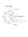
図1及び図2に示すように、回転型の装着ヘッド11に対して、その回転軸12を中心とする同一円周線に沿って、複数本(k本)の吸着ノズル13(N1 、N2 、N3 、…、Nk-2 、Nk-1 、Nk )が所定間隔で配列されて昇降可能に組み付けられている。 As shown in FIGS. 1 and 2, with respect to the
この部品装着機の運転を制御する制御装置(制御手段,画像処理手段)は、装着ヘッド11が部品吸着ステーション(部品供給装置から部品が供給される位置)上に位置するときに、装着ヘッド11の複数本の吸着ノズル13のうち、吸着・装着ポイントAに位置する吸着ノズル13(図1ではN1 )を下降させて部品を吸着して上昇させた後、装着ヘッド11を次の吸着ノズル13が吸着・装着ポイントAに到達するまで回転させて当該次の吸着ノズル13を下降させて部品を吸着して上昇させるという動作を繰り返して、複数本の吸着ノズル13に順番に部品を吸着させる吸着サイクルを実行する。 The control device (control means, image processing means) for controlling the operation of the component mounting machine has a mounting
この吸着サイクル終了後に、装着ヘッド11を部品装着ステーション上(回路基板の上方)へ移動させて、装着ヘッド11の複数本の吸着ノズル13のうち、吸着・装着ポイントAに位置する吸着ノズル13を下降させて部品を回路基板に装着して当該吸着ノズル13を上昇させた後、装着ヘッド11を次の吸着ノズル13が吸着・装着ポイントAに到達するまで回転させて当該次の吸着ノズル13を下降させて部品を回路基板に装着して上昇させるという動作を繰り返して、複数本の吸着ノズル13に吸着されていた部品を順番に回路基板に装着する装着サイクルを実行する。 After the suction cycle is completed, the mounting
この装着サイクル終了後に、装着ヘッド11を部品装着ステーションから部品吸着ステーション上へ戻して吸着サイクルを実行するという動作を繰り返して部品装着作業を実行する。 After the end of this mounting cycle, the component mounting operation is performed by repeating the operation of returning the mounting
本実施例では、吸着・装着ポイントA以外の特定の停止ポイント、例えば吸着・装着ポイントAに対して吸着サイクルでの装着ヘッド11の回転方向(正方向)に隣接する停止ポイントを撮像ポイントBとして、この撮像ポイントBで停止している吸着ノズル13の部品吸着状態を撮像するようにカメラ14を装着ヘッド11に取り付けると共に、吸着サイクルと装着サイクルとで装着ヘッド11の回転方向を反対にする。そして、吸着サイクルと装着サイクルで、それぞれ、吸着・装着ポイントAに位置する吸着ノズル13が部品の吸着・装着動作を行う期間に、カメラ14で撮像した画像データを取り込んで前記撮像ポイントBで停止している吸着ノズル13の部品未吸着や部品吸着姿勢の異常の有無を判定する。 In the present embodiment, a specific stop point other than the suction / mounting point A, for example, a stop point adjacent to the suction / mounting point A in the rotation direction (positive direction) of the mounting
この場合、吸着サイクル中に部品未吸着を検出したときには、当該吸着サイクルにおいて部品未吸着が検出された吸着ノズル13を再び吸着・装着ポイントAまで移動させて部品吸着動作を再実行する。このようにすれば、吸着サイクル中にいずれかの吸着ノズル13で部品未吸着が発生しても、当該吸着サイクルで部品の再吸着を行うことができる。 In this case, when the component non-adsorption is detected during the adsorption cycle, the
また、吸着サイクル中に部品吸着姿勢の異常を検出した場合には、当該部品吸着姿勢の異常が検出された吸着ノズル13については次の装着サイクルで部品装着動作を行わないようにすると共に、当該吸着ノズル13の再吸着動作は、次回の吸着サイクルで行うようにする。このようにすれば、部品吸着姿勢が異常な吸着ノズル13の部品装着動作を未然に防止することができ、部品装着不良が発生することを未然に防止できる。なお、吸着姿勢が異常であったため装着されなかった部品は、装着サイクル終了後に装着ヘッド11が部品吸着ステーション上に移動する間に、廃棄したり、回収トレイ・コンベア上に載せる等の処理を行う。 In addition, when an abnormality in the component suction posture is detected during the suction cycle, the
また、装着サイクル中に、部品装着動作前の吸着ノズル13について部品未吸着又は部品吸着姿勢の異常を検出した場合には、当該吸着ノズル13については部品装着動作を行わなず、次回の吸着サイクルで当該吸着ノズル13に部品を吸着させるようにする。このようにすれば、部品未吸着の吸着ノズル13が無駄な部品装着動作を行わずに済むと共に、部品未吸着の吸着ノズル13の先端が回路基板表面のクリーム半田や接着剤等に接触してこれらが吸着ノズル13の先端に付着することを未然に防止でき、装着ミス部品持ち帰りの発生を未然に防止できる。また、部品吸着姿勢が異常な吸着ノズル13の部品装着動作を未然に防止でき、部品装着不良が発生することを未然に防止できる。 In addition, when a component non-suction or an abnormality in the component suction posture is detected for the
また、装着サイクル終了後に装着ヘッド11を部品装着ステーションから部品吸着ステーション上へ移動させる際に、装着ヘッド11を回転させて複数の吸着ノズル13を順番に撮像ポイントBへ移動させてカメラ14で撮像した画像データを制御装置に取り込んで各吸着ノズル13の装着ミス部品持ち帰りの有無、及び、ゴミ・半田等の付着の有無を判定し、装着ミス部品持ち帰り又はゴミ・半田等の付着を検出したときには、適宜のエラー処理(警報動作等)を行う。このようにすれば、装着サイクルで、部品が回路基板に正常に装着されずに吸着ノズル13に張り付いたまま持ち帰られてしまう装着ミスが発生しても、その装着ミス部品持ち帰りを検出することができると共に、ゴミ・半田等の付着も検出することができ、適宜のエラー処理を行うことができる。これにより、装着ミス部品持ち帰りやゴミ・半田等の付着が生じた吸着ノズル13が部品の吸着・装着動作を繰り返して多数の不良回路基板を生産してしまうことを未然に防止できる。 Further, when the mounting
ところで、図4及び図5に示す比較例では、吸着・装着ポイントAに位置する吸着ノズル13の部品吸着状態を撮像するカメラ14を装着ヘッド11に取り付け、吸着・装着ポイントAに位置する吸着ノズル13が下降して部品を吸着・装着して元の位置まで上昇したところで、当該吸着ノズル13の部品吸着状態をカメラ14で撮像し、撮像終了後に、装着ヘッド11を次の吸着ノズル13が吸着・装着ポイントAに到達するまで回転させるという動作を繰り返して、装着ヘッド11の全ての吸着ノズル13の部品吸着状態を撮像するようにしている。 By the way, in the comparative example shown in FIGS. 4 and 5, a
しかし、この比較例の構成では、図5に示すように、各吸着ノズル13の部品吸着・装着動作終了後に開始されるカメラ14の撮像時間(画像データ取り込み時間)中は装着ヘッド11の回転を停止した状態に維持し、撮像終了後に装着ヘッド11の回転動作を開始して次の吸着ノズル13を吸着・装着ポイントAに移動させることになる。このため、カメラ撮像時間(画像データ取り込み時間)分だけサイクルタイムが増加して生産能率が低下したり、高速カメラが必要となり、コストアップするという欠点がある。 However, in the configuration of this comparative example, as shown in FIG. 5, the mounting
そこで、本実施例では、吸着・装着ポイントA以外の特定の停止ポイント(例えば吸着・装着ポイントAに対して吸着サイクルでの装着ヘッド11の回転方向に隣接する停止ポイント)を撮像ポイントBとして、この撮像ポイントBで停止している吸着ノズル13の部品吸着状態を撮像するようにしている。この場合、撮像ポイントBは吸着・装着ポイントA以外の停止ポイントであるため、この撮像ポイントBで停止している吸着ノズル13は、吸着・装着ポイントAの吸着ノズル13が部品の吸着・装着動作を行う期間に停止状態に維持される。このため、使用するカメラ14が比較的処理速度が遅いカメラであっても、図3に示すように、吸着・装着ポイントAの吸着ノズル13が部品の吸着・装着動作を行う期間をカメラ14の撮像時間に使用して、十分に時間的な余裕を持って吸着ノズル13の部品吸着状態の画像データを取り込むことができる。これにより、カメラ14の高速化を必要とせず、比較的低コストのカメラを使用できると共に、各吸着ノズル13の部品吸着・装着動作終了後のカメラ撮像時間が不要になるため、各吸着ノズル13の部品吸着・装着動作終了後に直ちに吸着ノズル13の回転動作を開始することができ、カメラ撮像時間(画像データ取り込み時間)によるサイクルタイムの増加がなく、サイクルタイムの短縮化の要求を満たすことができる。 Therefore, in this embodiment, a specific stop point other than the suction / mounting point A (for example, a stop point adjacent to the suction / mounting point A in the rotation direction of the mounting
更に、本実施例では、吸着サイクルと装着サイクルとで装着ヘッド11の回転方向を反対にするようにしているが、この理由は、吸着サイクルと装着サイクルとで装着ヘッド11を同じ方向に回転させると、吸着サイクルと装着サイクルのいずれか一方しか部品吸着状態を撮像できなくなってしまうためである。つまり、吸着サイクルでは、部品吸着動作後の部品吸着状態を撮像し、装着サイクルでは、部品装着動作前の部品吸着状態を撮像する必要があるが、吸着サイクルと装着サイクルとで装着ヘッド11を同じ方向に回転させると、吸着サイクルで部品吸着動作後の吸着ノズル13が撮像ポイントBを通過する場合は、装着サイクルでは部品装着動作を終了した吸着ノズル13のみが撮像ポイントBを通過するようになってしまい、部品装着動作前の部品吸着状態を撮像することができない。 Furthermore, in this embodiment, the rotation direction of the mounting
このように、吸着サイクルと装着サイクルとで装着ヘッド11を同じ方向に回転させる場合でも、吸着・装着ポイントAの両側にそれぞれカメラを1台ずつ配置すれば、吸着サイクルと装着サイクルの両方の部品吸着状態を撮像することが可能であるが、この構成では、2台のカメラを必要とするため、コスト高になるという欠点がある。 As described above, even when the mounting
これに対して、本実施例では、吸着サイクルと装着サイクルとで装着ヘッド11の回転方向を反対にするため、1台のカメラ14で吸着サイクルと装着サイクルの両方の部品吸着状態を撮像することが可能となり、低コスト化の要求を満たすことができる。 On the other hand, in this embodiment, since the rotation direction of the mounting
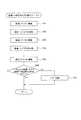
以上説明した本実施例の吸着サイクルと装着サイクルの制御は、部品装着機の制御装置(制御手段,画像処理手段)によって図6乃至図8の各ルーチンに従って実行される。以下、これら各ルーチンの処理内容を説明する。以下の説明では、装着ヘッド11に設けらたれたk本の吸着ノズル13のうち、吸着サイクルで最初に部品吸着動作を実行する吸着ノズル13を「吸着ノズルN1 」と表記し、以後、順番に「吸着ノズルN2 」、「吸着ノズルN3 」、……、「吸着ノズルNk-2 」、「吸着ノズルNk-1 」、「吸着ノズルNk 」と表記する。 The suction cycle and mounting cycle control of the present embodiment described above is executed according to the routines shown in FIGS. 6 to 8 by the control device (control unit, image processing unit) of the component mounting machine. The processing contents of these routines will be described below. In the following description, among the
[吸着サイクル制御ルーチン]
図6の吸着サイクル制御ルーチンは、吸着サイクル中に実行される。本ルーチンが起動されると、まずステップ101で、装着ヘッド11のk本の吸着ノズル13のうち、吸着・装着ポイントAに位置する1番目の吸着ノズルN1 を下降させて部品を吸着して上昇させる。この後、ステップ102に進み、装着ヘッド11を2番目の吸着ノズルN2 が吸着・装着ポイントAに到達するまで正方向に回転させる。これにより、部品吸着動作直後の1番目の吸着ノズルN1 が撮像ポイントBに到達する。[Adsorption cycle control routine]
The adsorption cycle control routine of FIG. 6 is executed during the adsorption cycle. When this routine is started, first, in
この後、ステップ103に進み、吸着・装着ポイントAに位置する2番目の吸着ノズルN2 を部品吸着動作させると共に、この部品吸着動作中に撮像ポイントBに位置する部品吸着動作直後の1番目の吸着ノズルN1 の部品吸着状態をカメラ14で撮像する。 Thereafter, the process proceeds to step 103, where the second suction nozzle N2 located at the suction / mounting point A is caused to perform the component suction operation, and the first suction immediately after the component suction operation located at the imaging point B during the component suction operation. The
これらの動作終了後に、ステップ104に進み、装着ヘッド11を3番目の吸着ノズルN3 が吸着・装着ポイントAに到達するまで正方向に回転させる。これにより、部品吸着動作直後の2番目の吸着ノズルN2 が撮像ポイントBに到達する。 After completion of these operations, the routine proceeds to step 104 where the mounting
この後、ステップ105に進み、吸着・装着ポイントAに位置する3番目の吸着ノズルN3 を部品吸着動作させると共に、この部品吸着動作中に撮像ポイントBに位置する部品吸着動作直後の2番目の吸着ノズルN2 の部品吸着状態をカメラ14で撮像する。 Thereafter, the process proceeds to step 105, where the third suction nozzle N3 located at the suction / mounting point A is caused to perform the part suction operation, and the second suction immediately after the part suction operation located at the imaging point B during the part suction operation. The
以後、同様に、装着ヘッド11を正方向に回転させて(ステップ106)、吸着・装着ポイントAの吸着ノズルの部品吸着動作と撮像ポイントBの吸着ノズルの部品吸着状態の撮像を同時に実行するという動作を各吸着ノズル毎に順番に繰り返す。 Thereafter, similarly, the mounting
そして、最後の吸着ノズルNk の部品吸着動作とその1つ前の吸着ノズルNk-1 の部品吸着状態の撮像を同時に実行した後(ステップ107)、装着ヘッド11を正方向に回転させて、部品吸着動作直後の最後の吸着ノズルNk を撮像ポイントBまで移動させる。この後、ステップ109に進み、部品吸着動作直後の最後の吸着ノズルNk の部品吸着状態をカメラ14で撮像する。 After the component suction operation of the last suction nozzle Nk and the imaging of the component suction state of the previous suction nozzle Nk-1 are simultaneously executed (step 107), the mounting
以上のようにして、全ての吸着ノズルN1 〜Nk について部品吸着動作と部品吸着状態の撮像を行った後、ステップ110に進み、各吸着ノズルN1 〜Nk の部品吸着状態の撮像画像データに基づいて全ての吸着ノズルN1 〜Nk に部品が吸着されたか否かを判定し、全ての吸着ノズルN1 〜Nk に部品が吸着されたと判定されれば、吸着サイクルを終了して、ステップ112に進み、装着ヘッド11を部品吸着ステーションから部品装着ステーション上へ移動させて、後述する図7の装着サイクル制御ルーチンを実行する。 As described above, after the component suction operation and the component suction state are imaged for all of the suction nozzles N1 to Nk, the process proceeds to step 110, based on the captured image data of the component suction states of the suction nozzles N1 to Nk. It is determined whether or not the parts have been sucked by all the suction nozzles N1 to Nk. If it is determined that the parts have been picked up by all the suction nozzles N1 to Nk, the suction cycle is completed, and the process proceeds to step 112 to install the parts. The
これに対して、上記ステップ110で、いずれかの吸着ノズルが部品未吸着であると判定されれば、ステップ111に進み、リカバリ動作を実行する。このリカバリ動作では、部品未吸着が検出された吸着ノズルを再び吸着・装着ポイントAまで移動させて部品吸着動作を実行した後、当該吸着ノズルを撮像ポイントBまで移動させて当該吸着ノズルの部品吸着状態を撮像する。このリカバリ動作における装着ヘッド11の回転方向は、吸着サイクルの通常の回転方向と同じ方向(正方向)でも良いし、逆方向でも良く、或は、部品未吸着が検出された吸着ノズルと吸着・装着ポイントAとの間の距離が短い方向を選択して装着ヘッド11を回転させるようにしても良い。リカバリ動作終了後は、各吸着ノズルN1 〜Nk の位置をリカバリ動作前の元の位置に戻す。 On the other hand, if it is determined in
このリカバリ動作終了後に、ステップ112に進み、全ての吸着ノズルN1 〜Nk に部品が吸着されたか否かを判定し、再び部品の吸着に失敗した吸着ノズルが存在すれば、リカバリ動作を再実行する。そして、全ての吸着ノズルN1 〜Nk に部品が吸着されたことが確認された段階で、吸着サイクルを終了して、ステップ112に進み、装着ヘッド11を部品吸着ステーションから部品装着ステーション上へ移動させて図7の装着サイクル制御ルーチンを実行する。 After this recovery operation is completed, the process proceeds to step 112, where it is determined whether or not the parts have been picked up by all the picking nozzles N1 to Nk. If there is a picking nozzle that has failed to pick up the parts again, the recovery operation is re-executed. . Then, when it is confirmed that the parts have been sucked by all the suction nozzles N1 to Nk, the suction cycle is completed, and the process proceeds to step 112, where the mounting
[装着サイクル制御ルーチン]
図7の装着サイクル制御ルーチンは、装着サイクル終了後に装着ヘッド11が部品装着ステーション上まで移動された段階で実行される。図7の装着サイクル制御ルーチンが起動されると、まずステップ201で、撮像ポイントBに位置する部品吸着動作直前のk番目の吸着ノズルNk (吸着サイクルで最後に撮像した吸着ノズルNk )の部品吸着状態をカメラ14で撮像する。[Mounting cycle control routine]
The mounting cycle control routine of FIG. 7 is executed when the mounting
この後、ステップ202に進み、装着ヘッド11を吸着サイクルでの回転方向(正方向)とは逆方向に回転させて、撮像済みのk番目の吸着ノズルNk を吸着・装着ポイントAまで移動させる。これにより、「k−1」番目の吸着ノズルNk-1 が撮像ポイントBに到達する。 Thereafter, the process proceeds to step 202, where the mounting
そして、次のステップ203で、吸着・装着ポイントAに位置するk番目の吸着ノズルNk の部品吸着状態が正常であるか否かをカメラ14の撮像画像データに基づいて判定し、その部品吸着状態が正常であれば、ステップ204に進み、吸着・装着ポイントAに位置するk番目の吸着ノズルNk を下降させて部品を回路基板に装着して当該吸着ノズルNk を上昇させると共に、この部品装着動作中に撮像ポイントBに位置する部品装着動作直前の「k−1」番目の吸着ノズルNk-1 の部品吸着状態をカメラ14で撮像する。 In the
これに対して、上記ステップ203で、吸着・装着ポイントAに位置するk番目の吸着ノズルNk の部品吸着状態が異常(部品吸着姿勢が異常又は部品未吸着)であると判定されれば、ステップ205に進み、当該吸着ノズルNk ついては部品装着動作を行わず、撮像ポイントBに位置する部品装着動作直前の「k−1」番目の吸着ノズルNk-1 の部品吸着状態をカメラ14で撮像する処理のみを実行する。 On the other hand, if it is determined in
上記ステップ204又はステップ205の処理後、ステップ206に進み、装着ヘッド11を撮像済みの「k−1」番目の吸着ノズルNk-1 が吸着・装着ポイントAに到達するまで逆方向に回転させる。以後、上記ステップ203〜206と同様の処理を各吸着ノズル毎に順番に繰り返して、吸着・装着ポイントAの吸着ノズルの部品装着動作と撮像ポイントBの吸着ノズルの部品吸着状態の撮像を同時に実行した後、装着ヘッド11を逆方向に回転させる処理を各吸着ノズル毎に順番に実行し、いずれかの吸着ノズルで部品吸着状態の異常(部品吸着姿勢の異常又は部品未吸着)が検出されれば、当該吸着ノズルついては部品装着動作を行わず、撮像ポイントBに位置する部品装着動作直前の吸着ノズルの部品吸着状態をカメラ14で撮像する処理のみを実行する(ステップ206〜209)。 After the processing of
そして、最後の吸着ノズルN1 の部品吸着状態をカメラ14で撮像した後、ステップ210に進み、装着ヘッド11を撮像済みの吸着ノズルN1 が吸着・装着ポイントAに到達するまで逆方向に回転させる。 Then, after imaging the component suction state of the last suction nozzle N1 with the
そして、次のステップ211で、吸着・装着ポイントAに位置する吸着ノズルN1 の部品吸着状態が正常であるか否かをカメラ14の撮像画像データに基づいて判定し、その部品吸着状態が正常であれば、ステップ212に進み、吸着・装着ポイントAに位置する吸着ノズルN1 を部品装着動作させる。 In the
この後、ステップ213に進み、全ての吸着ノズルN1 〜Nk の部品吸着状態が正常であったか否かを判定し、全ての吸着ノズルN1 〜Nk の部品吸着状態が正常であった場合は、装着サイクルを終了して、装着ヘッド11を部品装着ステーションから部品吸着ステーション上へ戻して吸着サイクルを実行したり、或は、このまま部品装着作業を終了する場合もある。 Thereafter, the process proceeds to step 213, where it is determined whether or not the component suction states of all the suction nozzles N1 to Nk are normal. If the component suction states of all the suction nozzles N1 to Nk are normal, the mounting cycle is performed. In some cases, the mounting
これに対して、上記ステップ213で、いずれかの吸着ノズルの部品吸着状態が異常(部品吸着姿勢が異常又は部品未吸着)であると判定されれば、ステップ214に進み、リカバリ動作を実行する。このリカバリ動作では、装着ヘッド11を部品吸着ステーション上へ移動させて、部品吸着状態の異常が検出された吸着ノズルを、通常の吸着サイクルと同様の方法で吸着・装着ポイントAまで移動させて部品吸着動作を実行してカメラ14の撮像画像データに基づいて部品未吸着が無いことを確認した後、装着ヘッド11を部品装着ステーション上へ戻して、部品吸着状態の異常が検出された吸着ノズルについて、部品装着動作直前の部品吸着状態の撮像と部品装着動作を再実行する。 On the other hand, if it is determined in
この後、ステップ215に進み、全ての吸着ノズルN1 〜Nk の部品吸着状態が正常であったか否かを判定し、再び、いずれかの吸着ノズルで部品吸着状態の異常が検出されれば、リカバリ動作を再実行する。そして、全ての吸着ノズルN1 〜Nk の部品吸着状態が正常であったことが確認された段階で、装着サイクルを終了する。 Thereafter, the process proceeds to step 215, where it is determined whether or not the component suction states of all the suction nozzles N1 to Nk are normal, and if an abnormality in the component suction state is detected again by any of the suction nozzles, the recovery operation is performed. Try again. Then, when it is confirmed that the component suction states of all the suction nozzles N1 to Nk are normal, the mounting cycle is finished.
[装着ミス部品持ち帰り検出ルーチン]
図8の装着ミス部品持ち帰り検出ルーチンは、装着サイクル終了後に装着ヘッド11を部品装着ステーションから部品吸着ステーション上へ移動させる動作と並行して実行される。図8の装着ミス部品持ち帰り検出ルーチンが起動されると、まずステップ301で、撮像ポイントBに位置する吸着ノズルN1 の先端部分(正常装着時には部品が吸着されていない状態)をカメラ14で撮像する。[Mounting parts take-off detection routine]
8 is executed in parallel with the operation of moving the mounting
この後、ステップ302に進み、装着ヘッド11を2番目の吸着ノズルN2 が撮像ポイントBに到達するまで正方向に回転させ、次のステップ303で、当該2番目の吸着ノズルN2 の先端部分をカメラ14で撮像する。以後、装着ヘッド11の正方向回転と吸着ノズルの先端部分の撮像を各吸着ノズル毎に順番に繰り返す(ステップ304〜305)。 Thereafter, the process proceeds to step 302 where the mounting
以上のようにして、全ての吸着ノズルN1 〜Nk の先端部分をカメラ14で撮像した後、ステップ306に進み、各吸着ノズルN1 〜Nk の先端部分の撮像画像データに基づいていずれかの吸着ノズルで装着ミス部品持ち帰りやゴミ・半田等の付着が有るか否かを判定し、装着ミス部品持ち帰りやゴミ・半田等の付着が無ければ、そのまま本ルーチンを終了する。 As described above, after the front end portions of all the suction nozzles N1 to Nk are imaged by the
これに対して、上記ステップ306で、いずれかの吸着ノズルで装着ミス部品持ち帰りやゴミ・半田等の付着が有ると判定されれば、ステップ307に進み、警報動作等のエラー処理を実行して本ルーチンを終了する。 On the other hand, if it is determined in
尚、図8の装着ミス部品持ち帰り検出ルーチンでは、装着ヘッド11を正方向に回転させたが、逆方向に回転させて、吸着ノズルN1 〜Nk の先端部分を上記順序とは逆順でカメラ14で撮像するようにしても良い。 8, the mounting
この場合、「正方向」とは吸着サイクルでの装着ヘッド11の回転方向を意味する。この吸着サイクルでの装着ヘッド11の回転方向(正方向)は、図1において時計回り方向に限定されず、反時計回り方向であっても良いことは言うまでもない。 In this case, the “positive direction” means the rotation direction of the mounting
また、カメラ14で撮像する吸着ノズルN1 〜Nk の停止位置となる「特定の停止ポイント」は、吸着・装着ポイントA以外の停止ポイントのうち、吸着・装着ポイントAに対して吸着サイクルでの装着ヘッド11の回転方向(正方向)に隣接する停止ポイントを「特定の停止ポイント」とすれば良い。このようにすれば、吸着サイクルで各吸着ノズルN1 〜Nk の部品吸着動作直後に部品吸着状態を撮像して検査できると共に、装着サイクルで各吸着ノズルN1 〜Nk の部品装着動作直前に部品吸着状態を撮像して検査できる利点がある。
The “specific stop point” that is the stop position of the suction nozzles N1 to Nk picked up by the
11…装着ヘッド、12…回転軸、13(N1 〜Nk )…吸着ノズル、14…カメラ、A…吸着・装着ポイント、B…撮像ポイント(特定の停止ポイント) DESCRIPTION OF
Claims (6)
Translated fromJapanese前記装着ヘッドが部品吸着ステーション上に位置するときに、前記複数本の吸着ノズルのうち、吸着・装着ポイントに位置する吸着ノズルを下降させて部品を吸着して上昇させた後、前記装着ヘッドを次の吸着ノズルが前記吸着・装着ポイントに到達するまで回転させて当該次の吸着ノズルを下降させて部品を吸着して上昇させるという動作を繰り返して、前記複数本の吸着ノズルに順番に部品を吸着させる吸着サイクルを実行し、
この吸着サイクル終了後に前記装着ヘッドを部品装着ステーション上へ移動させて、前記複数本の吸着ノズルのうち、前記吸着・装着ポイントに位置する吸着ノズルを下降させて部品を回路基板に装着して上昇させた後、前記装着ヘッドを次の吸着ノズルが前記吸着・装着ポイントに到達するまで回転させて当該次の吸着ノズルを下降させて部品を前記回路基板に装着して上昇させるという動作を繰り返して、前記複数本の吸着ノズルに吸着されていた部品を順番に前記回路基板に装着する装着サイクルを実行し、
この装着サイクル終了後に前記装着ヘッドを前記部品装着ステーションから前記部品吸着ステーション上へ戻して前記吸着サイクルを実行するという動作を繰り返して部品装着作業を実行する制御手段を備えた部品装着機において、
前記吸着・装着ポイント以外の特定の停止ポイントで停止している吸着ノズルの部品吸着状態を撮像するように前記装着ヘッドに取り付けられたカメラと、
前記吸着サイクルと前記装着サイクルで、それぞれ、前記吸着・装着ポイントに位置する吸着ノズルが部品の吸着・装着動作を行う期間に前記カメラで撮像した画像データを取り込んで前記特定の停止ポイントで停止している吸着ノズルの少なくとも部品未吸着の有無を判定する画像処理手段とを備え、
前記制御手段は、前記吸着サイクルと前記装着サイクルとで前記装着ヘッドの回転方向を反対にし、
前記特定の停止ポイントは、前記吸着・装着ポイントに対して前記吸着サイクルでの前記装着ヘッドの回転方向に隣接する停止ポイントであることを特徴とする部品装着機。For a rotary mounting head, a plurality of suction nozzles are arranged at predetermined intervals along the same circumferential line around the rotation axis, and are provided so as to be lifted and lowered.
When the mounting head is positioned on the component suction station, the suction nozzle located at the suction / mounting point among the plurality of suction nozzles is lowered to suck and raise the component, and then the mounting head is moved. Rotate the next suction nozzle until it reaches the suction / mounting point, and repeat the operation of lowering the next suction nozzle and picking up and lifting the parts, and in order to place the parts on the plurality of suction nozzles in order. Run the adsorption cycle to adsorb,
After the suction cycle is completed, the mounting head is moved onto the component mounting station, and among the plurality of suction nozzles, the suction nozzle located at the suction / mounting point is lowered and the component is mounted on the circuit board and lifted. After that, the mounting head is rotated until the next suction nozzle reaches the suction / mounting point, and the next suction nozzle is lowered to repeat the operation of mounting the component on the circuit board and raising it. , Executing a mounting cycle in which the components that have been sucked by the plurality of suction nozzles are sequentially mounted on the circuit board;
In a component mounting machine comprising a control means for performing a component mounting operation by repeating the operation of returning the mounting head from the component mounting station onto the component suction station and executing the suction cycle after the end of this mounting cycle.
A camera attached to the mounting head so as to image the component suction state of the suction nozzle stopped at a specific stop point other than the suction / mounting point;
In the suction cycle and the mounting cycle, the image data captured by the camera is captured during a period in which the suction nozzle located at the suction / mounting point performs the suction / mounting operation of the component, and stops at the specific stop point. Image processing means for determining whether or not the suction nozzle is at least unsucked,
The control means reverses the rotation direction of the mounting head between the adsorption cycle and the mounting cycle,
The specific mounting point is a mounting point adjacent to the suction / mounting point in the rotation direction of the mounting head in the suction cycle .
前記制御手段は、前記画像処理手段が前記吸着サイクル中に部品吸着姿勢の異常を検出した場合に、当該部品吸着姿勢の異常が検出された吸着ノズルについては次の装着サイクルで部品装着動作を行わないことを特徴とする請求項1又は2に記載の部品装着機。The image processing means determines whether or not there is an abnormality in the component adsorption posture in addition to component non-adsorption during the adsorption cycle,
When the image processing unit detects an abnormality in the component suction posture during the suction cycle, the control unit performs a component mounting operation in the next mounting cycle for the suction nozzle in which the abnormality in the component suction posture is detected. component mounting machine according to claim 1or 2, characterized in that there is no.
前記制御手段は、前記画像処理手段が部品装着動作前の吸着ノズルについて部品未吸着又は部品吸着姿勢の異常を検出した場合に、当該吸着ノズルについては部品装着動作を行わないことを特徴とする請求項1乃至3のいずれかに記載の部品装着機。The image processing means determines whether or not there is a component non-suction or a component suction posture abnormality for the suction nozzle before performing a component mounting operation during the mounting cycle,
The control unit does not perform a component mounting operation for the suction nozzle when the image processing unit detects an unsucked component or an abnormality in a component suction posture with respect to the suction nozzle before the component mounting operation. Item mounting machine according to any one of Items 1 to3 .
前記装着ヘッドが部品吸着ステーション上に位置するときに、前記複数本の吸着ノズルのうち、前記吸着・装着ポイントに位置する吸着ノズルを下降させて部品を吸着して上昇させた後、前記装着ヘッドを次の吸着ノズルが前記吸着・装着ポイントに到達するまで回転させて当該次の吸着ノズルを下降させて部品を吸着して上昇させるという動作を繰り返して、前記複数本の吸着ノズルに順番に部品を吸着させる吸着サイクルを実行し、
この吸着サイクル終了後に前記装着ヘッドを部品装着ステーション上へ移動させて、前記複数本の吸着ノズルのうち、前記吸着・装着ポイントに位置する吸着ノズルを下降させて部品を回路基板に装着して上昇させた後、前記装着ヘッドを次の吸着ノズルが前記吸着・装着ポイントに到達するまで回転させて当該次の吸着ノズルを下降させて部品を前記回路基板に装着して上昇させるという動作を繰り返して、前記複数本の吸着ノズルに吸着されていた部品を順番に前記回路基板に装着する装着サイクルを実行し、
この装着サイクル終了後に前記装着ヘッドを前記部品装着ステーションから前記部品吸着ステーション上へ戻して前記吸着サイクルを実行するという動作を繰り返して部品装着作業を実行する部品装着方法において、
前記吸着サイクルと前記装着サイクルとで前記装着ヘッドの回転方向を反対にすると共に、前記特定の停止ポイントは、前記吸着・装着ポイントに対して前記吸着サイクルでの前記装着ヘッドの回転方向に隣接する停止ポイントであり、
前記吸着サイクルと前記装着サイクルで、それぞれ、前記吸着・装着ポイントに位置する吸着ノズルが部品の吸着・装着動作を行う期間に、前記カメラで撮像した画像データを取り込んで前記特定の停止ポイントで停止している吸着ノズルの少なくとも部品未吸着の有無を判定することを特徴とする部品装着方法。For a rotary mounting head, a plurality of suction nozzles are arranged at predetermined intervals along the same circumference around the rotation axis, and can be moved up and down. Using a component mounting machine equipped with a camera attached to the mounting head so as to image the component suction state of the suction nozzle stopped at
When the mounting head is positioned on a component suction station, the mounting head is moved up by sucking a component by lowering the suction nozzle positioned at the suction / mounting point among the plurality of suction nozzles. Rotate the next suction nozzle until it reaches the suction / mounting point, and repeat the operation of lowering the next suction nozzle and picking up and lifting the parts. Execute an adsorption cycle to adsorb
After the suction cycle is completed, the mounting head is moved onto the component mounting station, and among the plurality of suction nozzles, the suction nozzle located at the suction / mounting point is lowered and the component is mounted on the circuit board and lifted. After that, the mounting head is rotated until the next suction nozzle reaches the suction / mounting point, and the next suction nozzle is lowered to repeat the operation of mounting the component on the circuit board and raising it. , Executing a mounting cycle in which the components that have been sucked by the plurality of suction nozzles are sequentially mounted on the circuit board;
In the component mounting method for performing the component mounting operation by repeating the operation of returning the mounting head from the component mounting station onto the component suction station and executing the suction cycle after the end of the mounting cycle,
The rotation direction of the mounting head is reversed between the suction cycle and the mounting cycle, and thespecific stop point is adjacent to the rotation direction of the mounting head in the suction cycle with respect to the suction / mounting point. Stop point,
During the suction cycle and the mounting cycle, the image data captured by the camera is captured and stopped at the specific stop point during the period in which the suction nozzle located at the suction / mounting point performs the part suction / mounting operation. A component mounting method comprising: determining whether or not at least a component is not attracted by a suction nozzle.
Priority Applications (1)
| Application Number | Priority Date | Filing Date | Title |
|---|---|---|---|
| JP2007014995AJP4840867B2 (en) | 2007-01-25 | 2007-01-25 | Component mounting machine and component mounting method |
Applications Claiming Priority (1)
| Application Number | Priority Date | Filing Date | Title |
|---|---|---|---|
| JP2007014995AJP4840867B2 (en) | 2007-01-25 | 2007-01-25 | Component mounting machine and component mounting method |
Publications (2)
| Publication Number | Publication Date |
|---|---|
| JP2008182095A JP2008182095A (en) | 2008-08-07 |
| JP4840867B2true JP4840867B2 (en) | 2011-12-21 |
Family
ID=39725754
Family Applications (1)
| Application Number | Title | Priority Date | Filing Date |
|---|---|---|---|
| JP2007014995AExpired - Fee RelatedJP4840867B2 (en) | 2007-01-25 | 2007-01-25 | Component mounting machine and component mounting method |
Country Status (1)
| Country | Link |
|---|---|
| JP (1) | JP4840867B2 (en) |
Families Citing this family (4)
| Publication number | Priority date | Publication date | Assignee | Title |
|---|---|---|---|---|
| JP6470469B2 (en)* | 2016-03-24 | 2019-02-13 | ヤマハ発動機株式会社 | Component mounter and nozzle imaging method thereof |
| CN111788881B (en)* | 2018-03-15 | 2021-09-10 | 株式会社富士 | Mounting device and control method of mounting device |
| JP2023030718A (en)* | 2021-08-24 | 2023-03-08 | パナソニックIpマネジメント株式会社 | Component mounting system and component mounting method |
| CN113838762B (en)* | 2021-09-06 | 2024-11-26 | 佑光智能半导体科技(深圳)有限公司 | Semiconductor mounting method |
Family Cites Families (8)
| Publication number | Priority date | Publication date | Assignee | Title |
|---|---|---|---|---|
| JP2003008291A (en)* | 2002-05-16 | 2003-01-10 | Fuji Mach Mfg Co Ltd | Electronic component mounter |
| JP2004319854A (en)* | 2003-04-17 | 2004-11-11 | Yamagata Casio Co Ltd | Component packaging apparatus and suction state detecting method |
| JP4421281B2 (en)* | 2003-12-12 | 2010-02-24 | ヤマハ発動機株式会社 | Component recognition method, component recognition device, surface mounter, component test device, and board inspection device |
| JP4421406B2 (en)* | 2004-07-27 | 2010-02-24 | ヤマハ発動機株式会社 | Surface mount machine |
| JP4494933B2 (en)* | 2004-10-26 | 2010-06-30 | Juki株式会社 | Electronic component mounting equipment |
| JP2006135159A (en)* | 2004-11-08 | 2006-05-25 | Matsushita Electric Ind Co Ltd | Component adsorption detection device and detection method, component mounting device and component mounting method |
| JP4546935B2 (en)* | 2005-02-14 | 2010-09-22 | パナソニック株式会社 | Component mounting method, component mounting machine, and program |
| JP4634204B2 (en)* | 2005-04-05 | 2011-02-16 | Juki株式会社 | Electronic component mounting equipment |
- 2007
- 2007-01-25JPJP2007014995Apatent/JP4840867B2/ennot_activeExpired - Fee Related
Also Published As
| Publication number | Publication date |
|---|---|
| JP2008182095A (en) | 2008-08-07 |
Similar Documents
| Publication | Publication Date | Title |
|---|---|---|
| JP6462000B2 (en) | Component mounter | |
| JP6421320B2 (en) | Component mounting method | |
| EP2538373B1 (en) | Picking system | |
| JP4904237B2 (en) | Substrate processing apparatus, surface mounting machine, printing machine, inspection machine, and coating machine | |
| JP4865496B2 (en) | Imaging apparatus and imaging method | |
| JP6021560B2 (en) | Parts inspection method and apparatus | |
| JP6717816B2 (en) | Component mounter | |
| JP2017220544A (en) | Component mounter | |
| JP4758263B2 (en) | Component transfer device, surface mounter and component inspection device | |
| JPH1013093A (en) | Electronic component mounting method | |
| JP2008218706A (en) | Component transfer device, surface mounter, and electronic component inspection device | |
| JP4840867B2 (en) | Component mounting machine and component mounting method | |
| JP2016103574A (en) | Classification device | |
| JP2003304100A (en) | Component placement management method, placement inspection device and placement system | |
| JP2013243273A (en) | Component suction operation monitoring device and component presence detection device | |
| JP6037580B2 (en) | Component mounter | |
| JP4455260B2 (en) | Component conveying device, surface mounter and component testing device | |
| JP2021158372A (en) | Parts mounting machine | |
| US20190380237A1 (en) | Component mounting device | |
| JP6470469B2 (en) | Component mounter and nozzle imaging method thereof | |
| JP5408148B2 (en) | Component mounting apparatus and component mounting method | |
| JP6587086B2 (en) | Component mounting method | |
| JP6883663B2 (en) | Parts mounting machine | |
| JP6997069B2 (en) | Parts mounting machine | |
| JP6652787B2 (en) | Mounting apparatus and control method thereof |
Legal Events
| Date | Code | Title | Description |
|---|---|---|---|
| A621 | Written request for application examination | Free format text:JAPANESE INTERMEDIATE CODE: A621 Effective date:20091005 | |
| A977 | Report on retrieval | Free format text:JAPANESE INTERMEDIATE CODE: A971007 Effective date:20110616 | |
| A131 | Notification of reasons for refusal | Free format text:JAPANESE INTERMEDIATE CODE: A131 Effective date:20110620 | |
| A521 | Request for written amendment filed | Free format text:JAPANESE INTERMEDIATE CODE: A523 Effective date:20110810 | |
| TRDD | Decision of grant or rejection written | ||
| A01 | Written decision to grant a patent or to grant a registration (utility model) | Free format text:JAPANESE INTERMEDIATE CODE: A01 Effective date:20110929 | |
| A01 | Written decision to grant a patent or to grant a registration (utility model) | Free format text:JAPANESE INTERMEDIATE CODE: A01 | |
| A61 | First payment of annual fees (during grant procedure) | Free format text:JAPANESE INTERMEDIATE CODE: A61 Effective date:20110929 | |
| R150 | Certificate of patent or registration of utility model | Ref document number:4840867 Country of ref document:JP Free format text:JAPANESE INTERMEDIATE CODE: R150 Free format text:JAPANESE INTERMEDIATE CODE: R150 | |
| FPAY | Renewal fee payment (event date is renewal date of database) | Free format text:PAYMENT UNTIL: 20141014 Year of fee payment:3 | |
| R250 | Receipt of annual fees | Free format text:JAPANESE INTERMEDIATE CODE: R250 | |
| R250 | Receipt of annual fees | Free format text:JAPANESE INTERMEDIATE CODE: R250 | |
| R250 | Receipt of annual fees | Free format text:JAPANESE INTERMEDIATE CODE: R250 | |
| R250 | Receipt of annual fees | Free format text:JAPANESE INTERMEDIATE CODE: R250 | |
| S533 | Written request for registration of change of name | Free format text:JAPANESE INTERMEDIATE CODE: R313533 | |
| R350 | Written notification of registration of transfer | Free format text:JAPANESE INTERMEDIATE CODE: R350 | |
| R250 | Receipt of annual fees | Free format text:JAPANESE INTERMEDIATE CODE: R250 | |
| R250 | Receipt of annual fees | Free format text:JAPANESE INTERMEDIATE CODE: R250 | |
| R250 | Receipt of annual fees | Free format text:JAPANESE INTERMEDIATE CODE: R250 | |
| R250 | Receipt of annual fees | Free format text:JAPANESE INTERMEDIATE CODE: R250 | |
| R250 | Receipt of annual fees | Free format text:JAPANESE INTERMEDIATE CODE: R250 | |
| R250 | Receipt of annual fees | Free format text:JAPANESE INTERMEDIATE CODE: R250 | |
| LAPS | Cancellation because of no payment of annual fees |