JP4839307B2 - Apparatus and method for treating hardened vascular lesions - Google Patents
Apparatus and method for treating hardened vascular lesionsDownload PDFInfo
- Publication number
- JP4839307B2 JP4839307B2JP2007505113AJP2007505113AJP4839307B2JP 4839307 B2JP4839307 B2JP 4839307B2JP 2007505113 AJP2007505113 AJP 2007505113AJP 2007505113 AJP2007505113 AJP 2007505113AJP 4839307 B2JP4839307 B2JP 4839307B2
- Authority
- JP
- Japan
- Prior art keywords
- balloon
- catheter
- incision
- catheter body
- compliance
- Prior art date
- Legal status (The legal status is an assumption and is not a legal conclusion. Google has not performed a legal analysis and makes no representation as to the accuracy of the status listed.)
- Expired - Lifetime
Links
- 0CC*N1CC1Chemical compoundCC*N1CC10.000description1
Images


Classifications
- A—HUMAN NECESSITIES
- A61—MEDICAL OR VETERINARY SCIENCE; HYGIENE
- A61M—DEVICES FOR INTRODUCING MEDIA INTO, OR ONTO, THE BODY; DEVICES FOR TRANSDUCING BODY MEDIA OR FOR TAKING MEDIA FROM THE BODY; DEVICES FOR PRODUCING OR ENDING SLEEP OR STUPOR
- A61M25/00—Catheters; Hollow probes
- A61M25/10—Balloon catheters
- A61M25/104—Balloon catheters used for angioplasty
- A—HUMAN NECESSITIES
- A61—MEDICAL OR VETERINARY SCIENCE; HYGIENE
- A61B—DIAGNOSIS; SURGERY; IDENTIFICATION
- A61B17/00—Surgical instruments, devices or methods
- A61B17/32—Surgical cutting instruments
- A61B17/3205—Excision instruments
- A61B17/3207—Atherectomy devices working by cutting or abrading; Similar devices specially adapted for non-vascular obstructions
- A61B17/320725—Atherectomy devices working by cutting or abrading; Similar devices specially adapted for non-vascular obstructions with radially expandable cutting or abrading elements
- A—HUMAN NECESSITIES
- A61—MEDICAL OR VETERINARY SCIENCE; HYGIENE
- A61B—DIAGNOSIS; SURGERY; IDENTIFICATION
- A61B17/00—Surgical instruments, devices or methods
- A61B2017/00831—Material properties
- A61B2017/00867—Material properties shape memory effect
- A—HUMAN NECESSITIES
- A61—MEDICAL OR VETERINARY SCIENCE; HYGIENE
- A61B—DIAGNOSIS; SURGERY; IDENTIFICATION
- A61B17/00—Surgical instruments, devices or methods
- A61B17/22—Implements for squeezing-off ulcers or the like on inner organs of the body; Implements for scraping-out cavities of body organs, e.g. bones; for invasive removal or destruction of calculus using mechanical vibrations; for removing obstructions in blood vessels, not otherwise provided for
- A61B2017/22051—Implements for squeezing-off ulcers or the like on inner organs of the body; Implements for scraping-out cavities of body organs, e.g. bones; for invasive removal or destruction of calculus using mechanical vibrations; for removing obstructions in blood vessels, not otherwise provided for with an inflatable part, e.g. balloon, for positioning, blocking, or immobilisation
- A61B2017/22061—Implements for squeezing-off ulcers or the like on inner organs of the body; Implements for scraping-out cavities of body organs, e.g. bones; for invasive removal or destruction of calculus using mechanical vibrations; for removing obstructions in blood vessels, not otherwise provided for with an inflatable part, e.g. balloon, for positioning, blocking, or immobilisation for spreading elements apart
- A—HUMAN NECESSITIES
- A61—MEDICAL OR VETERINARY SCIENCE; HYGIENE
- A61B—DIAGNOSIS; SURGERY; IDENTIFICATION
- A61B17/00—Surgical instruments, devices or methods
- A61B17/22—Implements for squeezing-off ulcers or the like on inner organs of the body; Implements for scraping-out cavities of body organs, e.g. bones; for invasive removal or destruction of calculus using mechanical vibrations; for removing obstructions in blood vessels, not otherwise provided for
- A61B2017/22051—Implements for squeezing-off ulcers or the like on inner organs of the body; Implements for scraping-out cavities of body organs, e.g. bones; for invasive removal or destruction of calculus using mechanical vibrations; for removing obstructions in blood vessels, not otherwise provided for with an inflatable part, e.g. balloon, for positioning, blocking, or immobilisation
- A61B2017/22065—Functions of balloons
- A61B2017/22069—Immobilising; Stabilising
- A—HUMAN NECESSITIES
- A61—MEDICAL OR VETERINARY SCIENCE; HYGIENE
- A61M—DEVICES FOR INTRODUCING MEDIA INTO, OR ONTO, THE BODY; DEVICES FOR TRANSDUCING BODY MEDIA OR FOR TAKING MEDIA FROM THE BODY; DEVICES FOR PRODUCING OR ENDING SLEEP OR STUPOR
- A61M25/00—Catheters; Hollow probes
- A61M25/10—Balloon catheters
- A61M2025/1043—Balloon catheters with special features or adapted for special applications
- A61M2025/1086—Balloon catheters with special features or adapted for special applications having a special balloon surface topography, e.g. pores, protuberances, spikes or grooves
- A—HUMAN NECESSITIES
- A61—MEDICAL OR VETERINARY SCIENCE; HYGIENE
- A61M—DEVICES FOR INTRODUCING MEDIA INTO, OR ONTO, THE BODY; DEVICES FOR TRANSDUCING BODY MEDIA OR FOR TAKING MEDIA FROM THE BODY; DEVICES FOR PRODUCING OR ENDING SLEEP OR STUPOR
- A61M25/00—Catheters; Hollow probes
- A61M25/10—Balloon catheters
- A61M2025/1043—Balloon catheters with special features or adapted for special applications
- A61M2025/109—Balloon catheters with special features or adapted for special applications having balloons for removing solid matters, e.g. by grasping or scraping plaque, thrombus or other matters that obstruct the flow
Landscapes
- Health & Medical Sciences (AREA)
- Life Sciences & Earth Sciences (AREA)
- Heart & Thoracic Surgery (AREA)
- Animal Behavior & Ethology (AREA)
- General Health & Medical Sciences (AREA)
- Engineering & Computer Science (AREA)
- Biomedical Technology (AREA)
- Veterinary Medicine (AREA)
- Public Health (AREA)
- Vascular Medicine (AREA)
- Surgery (AREA)
- Pulmonology (AREA)
- Child & Adolescent Psychology (AREA)
- Biophysics (AREA)
- Anesthesiology (AREA)
- Hematology (AREA)
- Molecular Biology (AREA)
- Medical Informatics (AREA)
- Nuclear Medicine, Radiotherapy & Molecular Imaging (AREA)
- Media Introduction/Drainage Providing Device (AREA)
- Surgical Instruments (AREA)
Description
Translated fromJapanese 1.発明の分野
本発明は医療機器の分野に関し、より詳細には、血管系内の狭窄症の処置を目的とした医療機器に関する。1. The present invention relates to the field of medical devices, and more particularly to medical devices intended for the treatment of stenosis in the vascular system.
バルーン拡張(血管形成)は、拡張バルーンを有するカテーテルを血管系内に挿入することにより狭窄血管の血行再建を行なうことを主に目的とする一般的な医療手順である。血管の内壁に径方向の圧力をかけ、血管内の狭窄領域を広げて血流を良くするために、狭窄領域内でバルーンを膨張させる。 Balloon dilatation (angiogenesis) is a general medical procedure whose main purpose is to revascularize stenotic blood vessels by inserting a catheter having an dilatation balloon into the vasculature. In order to apply a radial pressure to the inner wall of the blood vessel and widen the stenotic region in the blood vessel to improve blood flow, the balloon is inflated in the stenotic region.
多くの場合、このバルーン拡張手順の直後に、ステントを留置して血管形成後の血管開通を維持するステント留置手順が行なわれる。しかしながら、血管形成バルーンで狭窄血管を適切に拡げることができなければ、血管内でのステントの位置取りが不適切になる場合がある。薬剤溶出ステントを用いる場合、その有効性がそのような不適切な位置取りによって損なわれ、結果的に再狭窄率が高くなる可能性がある。これには、ステントと血管壁間の隙間の存在、バルーンによって適切に処置されなかった石灰化部位、などを含むいくつかの要因がある。 In many cases, a stent placement procedure is performed immediately after this balloon expansion procedure to place the stent and maintain vascular patency after angioplasty. However, if the stenotic blood vessel cannot be properly expanded with the angioplasty balloon, positioning of the stent within the blood vessel may become inappropriate. When using a drug eluting stent, its effectiveness can be compromised by such improper positioning, resulting in a high restenosis rate. This has several factors including the presence of a gap between the stent and the vessel wall, a calcification site that was not properly treated by the balloon, and the like.
同様に、従来のバルーン血管形成には、他にも多数の欠点がある。バルーン拡張手順は、罹患血管をその弾性限度以上に引き伸ばし得る強引なバルーンの膨張により血管に損傷を与える場合もある。そのような過剰な膨張は、血管壁を傷つけ、バルーンによって引き伸ばされた部分が再狭窄する可能性がある。他にも、拡張手順中にバルーンが滑脱する場合がある。これは、結果的に、処置された病変を覆う血管壁を損傷する可能性がある。滑脱が生じる可能性がある1つの手順は、現在血管形成バルーンでは処置が困難なステント内再狭窄の処置中である。繊維化した病変もまた、従来のバルーンを用いた処置が難しく、これらの病変を処置した後には、通常、弾性収縮が見られる。長い病変の多くが、血管形成バルーンを用いて処置することが困難な繊維化した部分を有する。 Similarly, conventional balloon angioplasty has a number of other disadvantages. Balloon dilation procedures may also damage the blood vessel by aggressive balloon inflation that can stretch the affected blood vessel beyond its elastic limits. Such excessive inflation can damage the vessel wall and restenose the portion stretched by the balloon. In other cases, the balloon may slip during the expansion procedure. This can result in damage to the vessel wall covering the treated lesion. One procedure in which slippage can occur is during the treatment of in-stent restenosis that is currently difficult to treat with angioplasty balloons. Fibrotic lesions are also difficult to treat with conventional balloons, and elastic contraction is usually seen after treating these lesions. Many long lesions have fibrotic parts that are difficult to treat with an angioplasty balloon.
バルーン血管形成による処置に関するさらなる問題としては、「ウォーターメロンシード効果(watermelon seed effect)」がある。血管形成は、代表的には、最大20気圧以上の非常に高い圧力で実施され、バルーンの半径方向外側からの圧力は、スイカの種を指で強く押したように、バルーンを軸方向にずらす可能性がある。このような軸方向のずれは、もちろん、バルーン拡張の有効性を低減する。従来の血管形成バルーン設計に関する他の問題としては、バルーンの収縮がある。膨張媒体をバルーンから取り除いた後でさえ、収縮構成は、脈管構造に入れられた元の折り畳み構成よりも大きな幅を有する。このような形状の増大は、バルーンの除去を困難にし得る。 A further problem with the treatment by balloon angioplasty is the “water melon seed effect”. Angiogenesis is typically performed at very high pressures of up to 20 atmospheres or more, and the pressure from the radially outer side of the balloon causes the balloon to shift axially as if the watermelon seed was pressed hard with a finger. there is a possibility. Such axial misalignment, of course, reduces the effectiveness of balloon expansion. Another problem with conventional angioplasty balloon designs is balloon deflation. Even after the inflation medium is removed from the balloon, the contracted configuration has a greater width than the original folded configuration placed in the vasculature. Such an increase in shape can make removal of the balloon difficult.
プラーク/血栓物質を除去することを目的とするアテローム切除/血栓摘出装置もまた、病変内で拡張する構造を備える場合があり、この構造内にプラーク/血栓除去メカニズムが存在する。除去された物質は、カテーテル内に堆積されるか、またはカテーテルを介して吸い出される。この手順が終わると、上記拡張可能な構造が縮小し、カテーテルが除去される。異物除去装置は、通常、異物を集めるために拡張し、その後、回収のために縮小する必要があるバスケット構造を備える。遠位保護装置は、通常、処置病変の遠位で拡張し、遊離性物体を集め、回収のために縮小する必要があるメッシュを支持するバスケット構造を備える。 An atherectomy / thrombectomy device intended to remove plaque / thrombotic material may also include a structure that expands within the lesion, within which there is a plaque / thrombus removal mechanism. The removed material is deposited in the catheter or aspirated through the catheter. At the end of this procedure, the expandable structure shrinks and the catheter is removed. Foreign matter removal devices typically include a basket structure that needs to be expanded to collect foreign matter and then reduced for collection. The distal protector typically includes a basket structure that supports a mesh that expands distal to the treatment lesion, collects free objects, and needs to be reduced for retrieval.
これらの装置は、通常、血管系内で拡張しその役割を果たした後、回収を容易にするために小径に縮小する必要がある伸縮性金属材料を備える。この縮小(閉)構成から拡張(開)構成への移行は、2つの方法で行なうことができる:上記構造は、通常は閉じた(縮小した)構成とすることができ、当該構造を拡張させるために力が加えられる。この場合、上記構造は、拡張させる力がなくなると、弾性収縮により縮小して閉構成に戻る。この構造はまた、通常は開いた(拡張した)構成であってもよく、上から拘束エレメントで押され、縮小構成とするために押えつけられる(例えば、拘束管)。この拘束エレメントが取り除かれると、この構造は、自由に拡張(開)構成に拡張させることができる。構造材料は非弾性であってもよい。この場合、上記構造は、縮小構成と拡張構成間の移行を強制的に行なう必要がある。 These devices typically comprise a stretchable metallic material that, after expanding and playing its role in the vasculature, needs to be reduced to a smaller diameter to facilitate retrieval. This transition from a reduced (closed) configuration to an expanded (open) configuration can be done in two ways: the structure can be a normally closed (reduced) configuration, which expands the structure. Power is applied for. In this case, when the expansion force is lost, the structure is contracted by elastic contraction and returns to the closed configuration. This structure may also be a normally open (expanded) configuration that is pushed from above with a restraining element and pressed into a reduced configuration (eg, a restraining tube). When the restraining element is removed, the structure can be freely expanded to an expanded (open) configuration. The structural material may be inelastic. In this case, the structure needs to forcibly shift between the reduced configuration and the expanded configuration.
従来の血管形成拡張システムに関する1つの問題は、縮小構成と拡張構成との間の移行が大きな回転反力および軸反力を伴うことである。これらの反力は、カテーテルが上記構造を拡張させるためまたは閉じるために力を加えた結果、当該構造によりカテーテル上に加えられる。軸反力は、上記構造が拡張時に縮むことにより生じる。回転反力(トルク)は、非長手方向側エレメントが拡張/縮小させられるときに生じる。カテーテルは、通常、上記構造ほど固くはないため、これらの反力により、当該構造が適切に拡張または縮小しなかったり、あるいは、カテーテル自体に不要な変形を生じたりする可能性がある。 One problem with conventional angioplasty dilation systems is that the transition between the contracted configuration and the expanded configuration involves large rotational and axial reaction forces. These reaction forces are exerted on the catheter by the structure as a result of the force applied by the catheter to expand or close the structure. The axial reaction force is generated when the above structure contracts during expansion. The rotational reaction force (torque) is generated when the non-longitudinal element is expanded / reduced. Since catheters are usually not as stiff as the above structures, these reaction forces may cause the structures to not expand or contract properly, or cause unnecessary deformation of the catheter itself.
これらの問題これらの問題の少なくともいくつかを克服するために、特許文献1は、バルーンに切断刃を付加することを記載している。これらの刃は、バルーンが膨張する際に病変を切断することが可能である。特許文献2は、バルーンに鋭利な切刃端を装着する同様の方法を記載している。特許文献3は、膨張時の血管形成バルーンを留めるための非軸方向グリップを有するステント状構造を記載している。特許文献4は、その外面に隆起部を有するバルーンカテーテルを記載している。特許文献5は、バルーン形状を小さくして、窮屈な病変を通過させる方法を記載している。特許文献6は、病変または狭窄内において長手方向に通路を作る可撓性細長エレメントを有するバルーン血管形成カテーテルを記載している。 These problems In order to overcome at least some of these problems, US Pat. These blades can cut the lesion as the balloon is inflated.
切断刃を有する血管形成バルーンの使用は、多くの状況において大いに有利であることが分かっているが、現在の切断バルーン設計およびそれらの使用法は、依然として欠点を有している。現在マサチューセッツ州ナティックのBOSTON SCIENTIFICが所有するカリフォルニア州サンディエゴのINTERVENTIONAL TECHNOLOGIES,INC.から入手可能なものを始めとする最も商業的な切断バルーン設計は、血管形成バルーンの外面上に比較的に長く、軸方向に並べられた刃を有する。代表的には、これらの刃は、バルーンの外面に直接装着された比較的硬質の基部上に取り付けられる。そのような硬質で、細長い刃構造を付加することにより、バルーン自体が非常に固くなり、バルーンを脈管構造の苦痛を与える領域、特に、冠状脈管構造内のより細い血管に入れる能力が制限される。さらに、切断バルーンは収縮および縮小が困難であり、切断刃を備えていない類似の血管形成バルーンの場合よりも、バルーンを脈管構造から除去することが困難になる可能性がある。また、そのような従来の切断バルーンにより施された軸方向に向けられた切断部は、所望される繊維化病変の改良された拡張および処置を必ずしも行なうとは限らない。 Although the use of angioplasty balloons with cutting blades has proven to be highly advantageous in many situations, current cutting balloon designs and their use still have drawbacks. INTERVENTIONAL TECHNOLOGIES, INC. Of San Diego, California, currently owned by BOSTON SCIENTIFIC of Natick, Massachusetts. Most commercial cutting balloon designs, including those available from, have relatively long, axially aligned blades on the outer surface of an angioplasty balloon. Typically, these blades are mounted on a relatively rigid base that is mounted directly on the outer surface of the balloon. By adding such a rigid, elongated blade structure, the balloon itself becomes very stiff and limits the ability of the balloon to enter into vascular pain areas, especially the smaller blood vessels within the coronary vasculature. Is done. Furthermore, the cutting balloon is difficult to contract and shrink, and it may be more difficult to remove the balloon from the vasculature than in the case of similar angioplasty balloons that do not have a cutting blade. Also, such axially oriented cuts made by such conventional cutting balloons do not necessarily provide improved dilation and treatment of the desired fibrotic lesion.
2.背景技術の説明
下記の米国特許および刊行物は、切断バルーンおよびバルーン構造に関する:特許文献7;特許文献8;特許文献5;特許文献9;特許文献10;特許文献11;特許文献12;特許文献13;特許文献14;特許文献15;特許文献16;特許文献17;特許文献18;特許文献19;特許文献2;特許文献20;特許文献21;特許文献1;特許文献22;特許文献23;および特許文献3。他の関連米国特許として、特許文献24;特許文献25;特許文献26;特許文献27;および特許文献28が挙げられる。
これらの理由のため、改良された切断バルーン設計およびそれらの使用法を提供することが望ましい。特に、バルーン構造の長さ全体に渡って非常に柔軟であり、容易に収縮させることができ、脈管構造からの除去を容易にし、罹患動脈の石灰化が進んだプラーク領域の処置、ステントを利用できない小血管および/または血管分岐部の処置、動脈口病変の処置、ならびにステント内再狭窄(ISR)の処置を含むがこれらに限定されないあらゆる形態の血管狭窄症の処置に効果的な切断バルーンを提供することが望ましい。さらに、このようなバルーン構造およびそれらの使用法が狭窄領域の拡張時に改良されたバルーンのアンカーリングを提供することが望ましい。 For these reasons, it is desirable to provide improved cutting balloon designs and their use. In particular, treatment of plaque areas, stents that are very flexible over the entire length of the balloon structure, can be easily deflated, facilitate removal from the vasculature and advanced calcification of the affected artery A cutting balloon effective for the treatment of all forms of vascular stenosis including, but not limited to, treatment of unavailable small vessels and / or vascular bifurcations, treatment of arterial lesions, and treatment of in-stent restenosis (ISR) It is desirable to provide Furthermore, it would be desirable for such balloon structures and their use to provide improved balloon anchoring during dilatation of the stenosis region.
外部構造がカテーテルに加える反力を最小化すると同時に、上記拡張可能な構造の拡張を制御することができればさらに望ましい。また、上記拡張可能な構造の材料または幾何学形状を変更することなく、予測可能な方法でシステムのコンプライアンスを調整することも望ましい。これらの目的のうち少なくともいくつかは、以下に記載の発明により達成される。 It would be further desirable to be able to control the expansion of the expandable structure while minimizing the reaction force applied to the catheter by the external structure. It is also desirable to adjust the compliance of the system in a predictable manner without changing the material or geometry of the expandable structure. At least some of these objectives will be achieved by the invention described below.
発明の要旨
本発明は、脈管構造内の狭窄領域を拡張するための改良された装置および方法を提供する。狭窄領域は、繊維化、石灰化もしくは他の硬化プラーク部位、または従来の血管形成バルーンを用いて拡張することが困難であり得るタイプの他の狭窄物質を含む場合が多い。これらの方法および装置は、冠動脈管構造を備えるがこれに限定されない動脈管構造の処置に最もよく利用される場合が多いが、静脈および/または末梢脈管構造の処置、ステントを利用できない小血管および/または血管分岐部の処置、動脈口病変の処置、ならびにISRの処置にも利用される場合がある。SUMMARY OF THE INVENTION The present invention provides an improved device and method for dilating a stenotic region within a vasculature. The stenotic region often includes fibrosis, calcification or other hardened plaque sites, or other types of stenotic material that can be difficult to expand using conventional angioplasty balloons. These methods and devices are most often used for the treatment of arterial vasculature, including but not limited to coronary vasculature, but for treatment of venous and / or peripheral vasculature, small vessels that cannot utilize stents And / or vascular bifurcation, arterial lesion treatment, and ISR treatment.
本発明の第1の局面では、切込形成カテーテルが、近位端および遠位端を有するカテーテル本体と、前記カテーテル本体の前記遠位端近傍で半径方向に拡張可能なシェル(代表的には、血管形成バルーン)と、前記シェル上に載せられる非軸方向の切込形成構造とを備える。「非軸方向の切込形成構造」とは、処置された血管内の狭窄物質に、一般に非軸方向の線に沿って切込を形成するかまたはそれを切断することができる構造を意味する。例えば、切込形成線は、らせん状、蛇行、ジグザグであってもよく、あるいはそのような非軸方向コンポーネントと軸方向コンポーネントを組み合わせてもよい。通常、得られる非軸方向の切込形成パターンは、全体的に見ると、通常は血管内壁の全体であるが少なくともその大部分に1回は外接し、好ましくは1回よりも多く、通常は2回よりも多く外接し、少なくとも3回外接することが多く、大抵は少なくとも4回、5回、または6回以上外接することが多い切込形成セグメントを備える。結果的に得られる血管内壁に外接する切込形成パターンは、その後のバルーン拡張時の結果を改良すると見られる。 In a first aspect of the invention, an incision catheter includes a catheter body having a proximal end and a distal end, and a radially expandable shell (typically, near the distal end of the catheter body). , An angioplasty balloon) and a non-axial incision forming structure placed on the shell. By “non-axial incision forming structure” is meant a structure capable of making or cutting an incision in a stenotic material within a treated blood vessel, generally along a non-axial line. . For example, the score line may be helical, serpentine, zigzag, or a combination of such non-axial and axial components. Usually, the resulting non-axial incision pattern is generally the entire inner wall of the blood vessel, but at least most of it is circumscribed once, preferably more than once, usually It has a notch segment that circumscribes more than two times, often circumscribed at least three times, and often circumscribed at least four times, five times, or more than six times. The resulting incision pattern circumscribing the vessel inner wall appears to improve the subsequent balloon dilation results.
通常、切込形成構造は、少なくとも1つの連続的な、すなわち、区切りのない切込形成エレメントを含み、このエレメントは少なくとも0.5cm、より普通には少なくとも1cmの長さを有し、少なくとも2cmの長さを有することも多く、通常は少なくとも3cmの長さで、場合によっては少なくとも4cm以上の長さを有する。あるいは、切込形成構造は、バルーン上にらせん状または他のパターンに配列され得る複数のはるかに小さなセグメントを含んでもよく、代表的には、このセグメントは0.1cm〜2cmの範囲の長さを有し、0.5cm以下の長さの場合も多く、0.3cm以下の長さの場合もある。 Typically, the incision forming structure comprises at least one continuous, ie uninterrupted, incision forming element, which element has a length of at least 0.5 cm, more usually at least 1 cm, and at least 2 cm. The length is usually at least 3 cm, and in some cases at least 4 cm. Alternatively, the incision structure may include a plurality of much smaller segments that can be arranged in a spiral or other pattern on the balloon, typically the segments having a length in the range of 0.1 cm to 2 cm. In many cases, the length is 0.5 cm or less, and the length is 0.3 cm or less.
下側の拡張可能なシェルが拡張した際に血管壁の切込形成を助長するために、切込形成構造は、通常、血管接触領域を有しており、この接触領域は、上記拡張可能なシェルの面積の20%以下であり、通常は10%を下回り、拡張可能なシェルの面積の1%〜5%の範囲である場合も多い。そのような比較的に小さな接触領域を有するシェルの使用により、下側の拡張可能なシェルの拡張によって上記構造を介して血管壁に加えられる力の量が増大する。切込形成構造は様々な特定の構成を有することができ、円形、正方形または他の断面形状を有するワイヤまたはスロット付きチューブの形態である場合が多い。好ましくは、切込形成構造のコンポーネントは、ホーニング刃、角型ショルダー等のいずれかの形態の切込形成エッジを備える。現在好まれる切込形成エッジは電解研磨されており、比較的小さい。 In order to facilitate incision formation of the vessel wall when the lower expandable shell is expanded, the incision forming structure typically has a vascular contact area that is expandable as described above. 20% or less of the area of the shell, usually less than 10% and often in the range of 1% to 5% of the area of the expandable shell. The use of a shell having such a relatively small contact area increases the amount of force applied to the vessel wall through the structure by expansion of the lower expandable shell. The cut-in structure can have a variety of specific configurations, often in the form of a wire or slotted tube having a circular, square or other cross-sectional shape. Preferably, the component of the cut forming structure comprises a cut forming edge in any form such as a honing blade, a square shoulder or the like. The currently preferred cut forming edge is electropolished and is relatively small.
好ましい実施形態では、切込形成構造は、カテーテルの拡張可能なシェル上に位置する個別の拡張式ケージとして形成されてもよい。このケージは、通常、拡張可能なシェルの片側でカテーテル本体上に配置するためのカラーまたは他のアタッチメント構造を各端部に有する。カラーは単純なチューブであってもよく、他のアタッチメント構造は、通常、蛇行したものまたは他のリング構造等、カテーテル本体にクリンプ可能であるかまたは機械的に装着可能である。このケージ上のアタッチメント構造は、両側がカテーテル本体に装着されてもよいが、より普通には一端のみが装着されており、他端は自由に浮遊するようにしている。このような自由度により、上記構造が拡張可能なシェル上で拡張した際に切込形成構造が短縮することが可能である。特定の実施形態では、切込形成構造の両端がカテーテル本体に固定されるが、上記アタッチメント構造のうちの少なくとも1つは、切込形成構造の中央が縮まった際に軸方向の拡張をもたらすバネまたは他のコンプライアンスアタッチメントコンポーネントを有する。 In a preferred embodiment, the incision forming structure may be formed as a separate expandable cage located on the expandable shell of the catheter. The cage typically has a collar or other attachment structure at each end for placement on the catheter body on one side of the expandable shell. The collar may be a simple tube and other attachment structures are usually crimpable or mechanically attachable to the catheter body, such as a serpentine or other ring structure. The attachment structure on the cage may be attached to the catheter body on both sides, but more usually only one end is attached, and the other end is allowed to float freely. With such a degree of freedom, it is possible to shorten the notch forming structure when the structure is expanded on an expandable shell. In certain embodiments, both ends of the incision forming structure are secured to the catheter body, but at least one of the attachment structures is a spring that provides axial expansion when the center of the incision forming structure contracts. Or have other compliance attachment components.
多くの場合、切込形成エレメントが非軸方向であるため、バルーンの拡張時および切込形成構造の短縮時にトルクが誘発される。これらのトルクは大きくてもよく、切込形成構造の一端で回転が抑制されると、切込形成エレメントは適切に拡張しない。切込形成エレメントの最終拡張構成は、短縮および回転により得られる。 In many cases, since the incision forming element is non-axial, torque is induced when the balloon is expanded and the incision formation is shortened. These torques may be large, and if rotation is constrained at one end of the cut forming structure, the cut forming element will not expand properly. The final expanded configuration of the incision forming element is obtained by shortening and rotation.
好ましい実施形態では、切込形成エレメントの両側がカテーテルに固定されるが、少なくとも一方側は、軸方向張力を生じると同時に、切込形成エレメントが回転してその最終構成になることを可能にするコンプライアンス構造を有する。 In a preferred embodiment, both sides of the incision forming element are secured to the catheter, but at least one side creates axial tension while simultaneously allowing the incision forming element to rotate to its final configuration. Has a compliance structure.
切込形成エレメントの両端が固定され、上記短縮がワイヤの変形により得られる場合もある。例えば、ワイヤは、伸びることを可能にする第2の構造(例えば、コイルフィラメントであってもよい)を有するようにすることができるか、または伸びることを可能にする材料、例えば、ニチノールで形成することができる。切込形成エレメントは、回転を可能にするように、両側を装着することができる。(切込形成エレメントの設計に応じて)トルクが小さい場合、回転の必要はなく、切込形成エレメントまたはカテーテルのいずれかによってトルクを吸収することができる。 In some cases, both ends of the incision forming element are fixed, and the shortening is obtained by deformation of the wire. For example, the wire can have a second structure that allows it to stretch (eg, it can be a coil filament) or can be formed of a material that allows it to stretch, such as Nitinol. can do. The incision forming element can be mounted on both sides to allow rotation. If the torque is small (depending on the design of the incision forming element), there is no need for rotation and the torque can be absorbed by either the incision forming element or the catheter.
あらゆる場合において、切込形成構造は、好ましくは、弾性材料で構成され、より好ましくは、ニチノール等の超弾性材料で構成される。よって、切込形成構造は、拡張可能なシェル、代表的には従来の血管形成バルーンと同様の膨張式バルーン上で弾力的に拡張される。収縮時には、切込形成構造は、弾力的に閉じてその元の非拡張構成に戻ることにより、バルーンまたは他の拡張可能なシェルを閉じて拡張を抑制する助けとなる。 In all cases, the notch forming structure is preferably composed of an elastic material, more preferably a superelastic material such as Nitinol. Thus, the incision forming structure is elastically expanded on an expandable shell, typically an inflatable balloon similar to a conventional angioplasty balloon. When deflated, the incision-forming structure helps close the balloon or other expandable shell and restrain expansion by resiliently closing back to its original unexpanded configuration.
切込形成エレメントは、1つより多くの材料の組み合わせである場合もある。1つの場合では、切込形成エレメントはニチノールで構成することができ、その一部をステンレス鋼で構成することができる。他の場合には、切込形成エレメントはステンレス鋼またはニチノールで構成することができ、その一部をポリマーで構成して変形を大きくすることができる。 The incision forming element may be a combination of more than one material. In one case, the incision forming element can be composed of nitinol, a portion of which can be composed of stainless steel. In other cases, the incision forming element can be composed of stainless steel or nitinol, a portion of which can be composed of polymer to increase deformation.
他の好ましい実施形態では、シェルと切込形成構造のアセンブリが十分な可撓性を有し、脈管構造のねじれた領域の通過を可能にするが、例えば、45°、90°以上に曲がった冠状脈管構造を進める際に10mm以下の半径で曲げることが可能である。通常、切込形成構造は1つ以上の切込形成エレメントを含み、切込形成エレメントの累積長の70%未満が、拡張時にシェル上で軸方向にそろえられるが、好ましくは、累積長の50%未満であり、より好ましくは、累積長の25%未満である。他の場合には、切込形成構造は1つ以上の切込形成エレメントを含んでもよく、切込形成エレメントの累積長は、少なくとも10mmの非軸方向コンポーネントを備えるが、好ましくは少なくとも12mmであり、より好ましくは36mmである。好ましくは、切込形成エレメントの少なくともいくつかが、膨張および収縮時ならびに膨張されている際に、その長さの少なくとも大半が常時半径方向外側に向けられた切込形成エッジを有する。「半径方向外側」とは、上記エレメントの鋭利なエッジまたはショルダーが、特にシェルが膨張しているときに、狭窄物質または処置された血管の内壁に切込を入れたり、それを切断するような方向に向けられたりすることを意味する。 In other preferred embodiments, the shell and incision forming assembly is sufficiently flexible to allow passage through torsional areas of the vasculature, but bend, for example, 45 °, 90 ° or more. When advancing the coronary vasculature, it can be bent with a radius of 10 mm or less. Typically, the cut forming structure includes one or more cut forming elements and less than 70% of the cumulative length of the cut forming elements is aligned axially on the shell when expanded, but preferably the cumulative length of 50 %, More preferably less than 25% of the cumulative length. In other cases, the incision forming structure may include one or more incision forming elements, the cumulative length of the incision forming elements comprising at least 10 mm non-axial components, but preferably at least 12 mm More preferably, it is 36 mm. Preferably, at least some of the incision elements have an incision edge whose length is always directed radially outward when expanded and contracted as well as when expanded. “Radially outside” means that the sharp edges or shoulders of the element make a cut or cut into the inner wall of the stenotic material or treated blood vessel, especially when the shell is inflated. It means being directed in the direction.
切込形成エレメントは、通常、それらの長さの少なくとも一部の上に切込形成エッジが形成されているが、必ずしもそのようにする必要はない。「切込形成エッジ」は、ナイフの刃の様に研がれたもしくはホーニングされた領域または鋏もしくは他の剪断のような角型のショルダーを含んでもよい。あるいは、切込形成エレメントは、明確な切込形成エッジがなくてもよく、例えば、円形または他の非切断形状を有する。そのような円形の切込形成エレメントは、バルーンの半径方向外側に向かう力を集中させて、処置されているプラークもしくは他の狭窄物質に切込形成または他の分裂を行なう。 Incision forming elements are usually provided with an incision forming edge on at least a portion of their length, but this is not necessarily so. “Incision edges” may include sharpened or honed areas like knife blades or square shoulders such as scissors or other shears. Alternatively, the incision forming element may not have a distinct incision forming edge, for example having a circular or other uncut shape. Such a circular incision element concentrates a force radially outward of the balloon to effect incision or other splitting on the plaque or other stenotic material being treated.
本発明の第2の局面では、切込形成カテーテルは、一般に上記で示したように、カテーテル本体および半径方向に拡張可能なシェルを備える。この切込形成構造は、この半径方向に拡張可能なシェルに外接するエレメントで構成される。「半径方向に拡張可能なシェルに外接する」とは、切込形成構造の少なくともいくつかの切込形成エレメントが、拡張時に、拡張可能なシェルの外部の周囲に連続した周辺経路を形成することを意味する。そのような完全外接構造の一例は、拡張前、拡張中および拡張後にバルーンの周囲に最大360°の経路を完成するらせん状構造であるが、通常は完全な2回転を完成させ、完全な3回転または4回転以上の場合も多い。例示的ならせん状構造は、2、3または4つ以上の個別のエレメントを含んでもよく、これらの各々は半径方向に拡張可能なシェル上でらせん状に配列される。 In a second aspect of the invention, the incision catheter generally comprises a catheter body and a radially expandable shell, as indicated above. This incision forming structure is composed of elements circumscribing the radially expandable shell. “Surrounding the radially expandable shell” means that at least some notch forming elements of the notch forming structure form a continuous peripheral path around the outside of the expandable shell when expanded. Means. An example of such a full circumscribing structure is a helical structure that completes a path of up to 360 ° around the balloon before, during, and after expansion, but usually completes two complete revolutions, There are many cases of rotation or four or more rotations. An exemplary helical structure may include two, three, four or more individual elements, each of which is arranged in a spiral on a radially expandable shell.
本発明の第3の局面では、切込形成カテーテルは、一般に上記で示したように、カテーテル本体と半径方向に拡張可能なシェルを備える。細長の切込形成構造がシェル上に載せられ、シェルと切込形成構造のアセンブリは可撓性が高く、ガイドワイヤ上への導入を容易にしているが、拡張していないときにねじれたり損傷したりすることなく少なくとも90°、好ましくは180°の角度で、1cmの半径に曲げられるように十分な可撓性を有することが好ましい。このような可撓性は、例えば、1cmの半径を有する固体円柱であって、当該円柱状に切込形成構造と拡張可能なシェルのアセンブリを適合させる固体円柱を設けることにより決定することができる。あるいは、上記アセンブリは、半径1センチの180°に折れ曲がった部分を有するガイドワイヤまたは同様のエレメント上を進めることができる。いずれの場合においても、アセンブリが、ねじれまたは他の損傷なしで曲がれば、上述した要件が満たされる。この本発明のカテーテルのさらなる実施形態における他の特定の特徴は、前述の実施形態に関連して上述したとおりである。 In a third aspect of the present invention, an incision catheter generally comprises a catheter body and a radially expandable shell, as indicated above. An elongate notch structure is placed on the shell, and the shell and notch structure assembly is highly flexible and easy to introduce onto the guidewire, but is twisted or damaged when not expanded It is preferable to have sufficient flexibility so that it can be bent to a radius of 1 cm at an angle of at least 90 °, preferably 180 ° without any undue effort. Such flexibility can be determined, for example, by providing a solid cylinder having a radius of 1 cm and adapting the notch forming structure and the expandable shell assembly to the cylinder. . Alternatively, the assembly can be advanced over a guidewire or similar element having a 1 centimeter radius of bent 180 °. In any case, if the assembly bends without twisting or other damage, the above requirements are met. Other specific features of this further embodiment of the catheter of the present invention are as described above in connection with the previous embodiment.
本発明の第4の局面では、プラーク切込形成カテーテルは、一般に上記で示したように、カテーテル本体および半径方向に拡張可能なバルーンを備える。複数の切込形成エレメントがバルーン上に分散しており、代表的にはバルーンの外面に直接装着されている。切込形成エレメントは比較的に短く、代表的にはバルーン長の約25%未満の長さであり、好ましくはバルーン長の2%〜10%の範囲の長さである。比較的に短く、セグメント化された切込形成エレメントにより、可撓性が高いバルーンと切込形成エレメントのアセンブリが一般に上記の可撓性要件を満たすことができる。切込形成エレメントは、バルーン上に不規則に配列されてもよいが、より普通には、バルーン上に均等に分散される。特定の実施形態では、切込形成エレメントは、バルーンに外接するらせん状、蛇行または他の規則的なパターンで配列されてもよい。バルーンが拡張する際、このような短いセグメントは、一般に、互いに離れていくが、それでもバルーンが膨張する際に血管壁に所望の切込形成パターンを作る。 In a fourth aspect of the present invention, a plaque incision catheter generally comprises a catheter body and a radially expandable balloon, as indicated above. A plurality of incision forming elements are dispersed on the balloon and are typically mounted directly on the outer surface of the balloon. The incision forming element is relatively short, typically less than about 25% of the balloon length, and preferably in the range of 2% to 10% of the balloon length. The relatively short and segmented cut forming element allows a highly flexible balloon and cut forming element assembly to generally meet the above flexibility requirements. The incision forming elements may be randomly arranged on the balloon, but more usually are evenly distributed on the balloon. In certain embodiments, the incision forming elements may be arranged in a spiral, serpentine or other regular pattern circumscribing the balloon. As the balloon expands, such short segments generally move away from each other, but still produce the desired incision pattern in the vessel wall as the balloon is inflated.
第5の実施形態では、本発明に係る切込形成カテーテルは、上記で示したように、カテーテル本体と半径方向に拡張可能なバルーンを備える。バルーンは、当該バルーンの端部間に延びる複数の突出部を有し、これらの突出部のうちの少なくとも1つに、バルーンが拡張した際に狭窄物質に切込を入れるように配列された少なくとも1つの切込形成エレメントが形成される。突出部は、通常、らせん状パターンであり、代表的には2、3個以上の突出部が設けられる。らせん状の突出部の場合、切込形成エレメントは、通常、バルーンが膨張した際にらせん状突出部によって規定されるらせん状の尖端部に沿って配置される。このようならせん状切込形成エレメントは、代表的には引き伸ばし可能であるか、セグメント化されている等、バルーンの膨張に対応するように配列される。 In a fifth embodiment, an incision forming catheter according to the present invention comprises a catheter body and a radially expandable balloon as indicated above. The balloon has a plurality of protrusions extending between the ends of the balloon, and at least one of the protrusions is at least arranged to cut into the stenotic material when the balloon is expanded. One incision forming element is formed. The protrusions are usually in a spiral pattern, and typically a few or more protrusions are provided. In the case of a helical protrusion, the incision forming element is typically placed along the helical tip defined by the helical protrusion when the balloon is inflated. Such helical incision elements are typically arranged to accommodate balloon inflation, such as being stretchable or segmented.
本発明の装置のさらに他の局面では、拡張式切込形成ケージは、バルーンカテーテルのバルーン上に載せられるように適合される。切込形成ケージは、非軸方向パターンで配列された1つ以上の細長の弾力性切込形成エレメントのアセンブリを備える。上記で定義したように、非軸方向パターンは、軸方向セグメントおよび非軸方向セグメントの両方を備えてもよい。上記アセンブリは、通常、半径方向に縮小した構成であり、バルーン上で拡張して半径方向に拡張した構成にすることが可能である。バルーンが収縮すると、アセンブリは、好ましくは切込形成ケージの弾力性の助力を得て半径方向に縮小した構成に戻る。切込形成ケージが下側のバルーンまたは他の拡張可能なシェルの均等な拡張を助長し、血管形成バルーンの各端部が過剰に膨張して血管解離の危険性を増大させる傾向にある「ドッグボーニング(dog−boning)」を防ぐことは有利である。切込形成エレメントは、血管内腔内でバルーンにより拡張された際にプラークまたは繊維化物質等、硬化した狭窄物質に切込を入れるように適合される。切込形成ケージは、一般に前述した実施形態に関連して上述したように、一端または両端がバルーンに貼り付けられた状態でバルーンに取り付けられるように適合させてもよい。切込形成エレメントの好適な幾何学形状は、バルーンと外接する形状、バルーン上でらせん状に配列される形状、バルーン上で蛇行パターンで配列される形状等を備える。 In yet another aspect of the device of the present invention, the expandable incision cage is adapted to be placed on the balloon of a balloon catheter. The incision cage comprises an assembly of one or more elongated resilient incision elements arranged in a non-axial pattern. As defined above, the non-axial pattern may comprise both axial and non-axial segments. The assembly is typically a radially reduced configuration and can be expanded on the balloon to a radially expanded configuration. When the balloon is deflated, the assembly returns to a radially contracted configuration, preferably with the aid of the elasticity of the notching cage. “Dogs” where the incision cage facilitates even expansion of the underlying balloon or other expandable shell, and each end of the angioplasty balloon tends to over-inflate, increasing the risk of vascular dissection It is advantageous to prevent “dog-boning”. The incision element is adapted to make an incision in a hardened stenotic material, such as plaque or fibrotic material, when expanded by a balloon within the vessel lumen. The incision forming cage may be adapted to be attached to the balloon with one or both ends affixed to the balloon, generally as described above in connection with the previously described embodiments. Suitable geometric shapes of the incision forming element include a shape circumscribing the balloon, a shape arranged in a spiral on the balloon, a shape arranged in a serpentine pattern on the balloon, and the like.
本発明のさらに他の局面では、血管内の狭窄領域を拡張する方法は、切込形成構造を載せるシェルを半径方向に拡張させる工程を包含する。切込形成構造は狭窄領域に切込を入れて拡張し、シェルが拡張された際に血管の内壁周りに外接切込パターンを作るように配列された1つ以上の非軸方向の切込形成エレメントを備える。狭窄領域は、代表的には、石灰化プラーク、繊維化プラークまたは拡張前に切込が入れられることが好ましい他の硬化狭窄物質が存在することを特徴とする。好ましくは、切込形成構造は、狭窄領域とかみ合っている間は軸方向には移動せず、任意に、切込形成構造を軸方向切込形成エレメントと固定しないようにしてもよい。 In yet another aspect of the present invention, a method for expanding a stenotic region in a blood vessel includes radially expanding a shell on which an incision forming structure is placed. The incision structure is inflated by making incisions in the stenotic region and one or more non-axial incisions arranged to create a circumscribed incision pattern around the inner wall of the blood vessel when the shell is expanded With elements. The stenotic region is typically characterized by the presence of calcified plaques, fibrotic plaques or other hardened stenotic material that is preferably incised prior to expansion. Preferably, the incision forming structure does not move axially while engaging the constriction region, and optionally the incision forming structure may not be secured to the axial incision forming element.
本発明のさらに他の局面では、血管形成カテーテルは、カテーテル本体およびカテーテル本体の遠位端近傍で半径方向に拡張可能なシェルを備える。切込形成構造または切断構造等の外部構造は、シェル上に載せられるが当該シェルには装着されていない。カテーテルは、近位端および切込形成構造に装着された遠位端を有するアタッチメント構造であって、切込形成構造がシェルによって拡張させられた際に生じた反力および寸法形状の変化に対応するために十分な大きさとコンプライアンスを有するアタッチメント構造をさらに備える。一般に、上記切込形成構造の少なくとも一部は、シェル上でらせん状に配列される。しかしながら、切込形成構造は、上述したような種々の異なる構成を有してもよい。 In yet another aspect of the invention, an angioplasty catheter comprises a catheter body and a radially expandable shell near the distal end of the catheter body. An external structure such as a cut forming structure or a cutting structure is mounted on the shell but is not attached to the shell. The catheter is an attachment structure having a proximal end and a distal end attached to the incision forming structure, which responds to reaction forces and dimensional changes that occur when the incision forming structure is expanded by the shell. And an attachment structure having a size and compliance sufficient for the purpose. Generally, at least a part of the notch forming structure is arranged in a spiral on the shell. However, the cut forming structure may have various different configurations as described above.
本発明の1つの局面では、アタッチメント構造の近位端はカテーテル本体に固定され、アタッチメント構造の遠位端は切込形成構造の近位端に止められる。あらゆる場合において、アタッチメント構造は、シェルが拡張された際に、軸方向および回転方向に延びて切込形成構造の縮みに対応することができる。 In one aspect of the invention, the proximal end of the attachment structure is secured to the catheter body, and the distal end of the attachment structure is stopped at the proximal end of the notch forming structure. In all cases, the attachment structure can extend axially and rotationally to accommodate the shrinkage of the notch forming structure when the shell is expanded.
好ましい実施形態では、アタッチメント構造は、アタッチメント構造は、外径および内径を有し、カテーテル本体上を延びるコンプライアンスチューブを備える。コンプライアンスチューブの内径は、一般に、カテーテル本体の外径よりも大きく、コンプライアンスチューブは、切込形成構造が縮まった際にカテーテル本体に対して自由に伸び、かつ/もしくは回転する。 In a preferred embodiment, the attachment structure comprises a compliance tube that has an outer diameter and an inner diameter and extends over the catheter body. The inner diameter of the compliance tube is generally larger than the outer diameter of the catheter body, and the compliance tube freely extends and / or rotates relative to the catheter body when the incision forming structure is contracted.
コンプライアンスチューブはまた、切込形成構造と拡張可能なシェルのコンプライアンスを制御する大きさにすることもできる。一般には、コンプライアンスチューブは、コンプライアンスチューブは、0.001インチ〜0.1インチの範囲の肉厚を有し、好ましくは、0.005インチ〜0.05インチである。この肉厚は、システムのコンプライアンスを低くするように厚くしても、高いコンプライアンスを得るために薄くしてもよい。コンプライアンスチューブの長さも、システムのコンプライアンスを制御するように調節してもよい。一般に、コンプライアンスチューブは、1cm〜10cmの範囲の長さを有するが、チューブがカテーテル本体の長さに渡って延びる実施形態の場合には最大30cm以上の範囲にしてもよい。 The compliance tube can also be sized to control the notch forming structure and the compliance of the expandable shell. Generally, the compliance tube has a wall thickness in the range of 0.001 inch to 0.1 inch, preferably 0.005 inch to 0.05 inch. This wall thickness may be increased to reduce system compliance or may be decreased to achieve higher compliance. The length of the compliance tube may also be adjusted to control system compliance. In general, the compliance tube has a length in the range of 1 cm to 10 cm, but in embodiments in which the tube extends over the length of the catheter body, it may be in the range of up to 30 cm or more.
多くの場合、コンプライアンスチューブの材料は、切込形成構造と拡張可能なシェルのコンプライアンスを制御するように選択されてもよい。一般に、コンプライアンスチューブは弾性材料を含んでおり、好ましくはナイロンまたはペバックスTM等のポリマーである。あるいは、コンプライアンスチューブは、編組物質、金属またはワイヤメッシュを含んでもよい。In many cases, the material of the compliance tube may be selected to control the compliance of the notch forming structure and the expandable shell. In general, the compliance tube comprises an elastic material, preferably a polymer such as nylon or Pebax™ . Alternatively, the compliance tube may comprise braided material, metal or wire mesh.
本発明のいくつかの局面では、コンプライアンスチューブは、切込形成構造と拡張可能なシェルのコンプライアンスを制御するための1つ以上の穿孔を有してもよい。一般に、これらの穿孔は、コンプライアンスチューブの外周に沿って延びる1つ以上のスロットを備える。これらのスロットは、コンプライアンスチューブの外周に沿ってパターンを形成してもよい。これらのスロットは相互に平行であってもよく、かつ/あるいはコンプライアンスチューブの周囲を渡ってらせん状または半径方向に延びてもよい。これらのスロットは、それ自体が円形または矩形等、種々の形で形成されていてもよい。 In some aspects of the invention, the compliance tube may have one or more perforations to control the compliance of the notch forming structure and the expandable shell. In general, these perforations comprise one or more slots that extend along the outer periphery of the compliance tube. These slots may form a pattern along the outer periphery of the compliance tube. These slots may be parallel to each other and / or extend helically or radially around the periphery of the compliance tube. These slots may themselves be formed in various shapes, such as circular or rectangular.
好ましくは、コンプライアンスチューブは、その遠位端から近位端に向かって先細りする外径を有するため、近位端の外径は内径よりも若干大きく、遠位端の外径は、縮小構成時に、切込形成構造の直径に近似する大きさである。これによって、血管壁につかえたり、引っかかったりすることなくカテーテルを血管から容易に取り除くことが可能になる。先細り形状の構成については、コンプライアンスチューブの外径は、カテーテル本体と拡張ケージのサイズに応じて変わるが、直径は、一般に、遠位端から近位端に向かって0.004インチ〜0.010インチの範囲で先細りする。 Preferably, the compliance tube has an outer diameter that tapers from its distal end toward the proximal end, so the outer diameter of the proximal end is slightly larger than the inner diameter, and the outer diameter of the distal end is The size approximates the diameter of the notch forming structure. This allows the catheter to be easily removed from the blood vessel without being caught or caught on the vessel wall. For tapered configurations, the outer diameter of the compliance tube will vary depending on the size of the catheter body and expansion cage, but the diameter is generally 0.004 inches to 0.010 from the distal end to the proximal end. Taper in inches.
この発明の他の局面では、アタッチメント構造は、遠位端が切込形成構造に接続され、近位端がマニピュレータに接続される。代表的には、マニピュレータは、カテーテル本体の近位端に位置し、アタッチメント構造は、切込形成構造からカテーテル本体の長さに渡って延びる。あらゆる場合において、アタッチメント構造は、シェルが拡張された際に、軸方向および回転方向に延びて切込形成構造の縮みに対応することができる。 In another aspect of the invention, the attachment structure has a distal end connected to the notch forming structure and a proximal end connected to the manipulator. Typically, the manipulator is located at the proximal end of the catheter body and the attachment structure extends from the incision forming structure over the length of the catheter body. In all cases, the attachment structure can extend axially and rotationally to accommodate the shrinkage of the notch forming structure when the shell is expanded.
好ましい実施形態では、アタッチメント構造は、外径および内径を有し、カテーテル本体上を延びるコンプライアンスチューブを備える。代表的には、コンプライアンスチューブの内径はカテーテル本体の外径よりも大きく、コンプライアンスチューブは、切込形成構造が縮まった際にカテーテル本体に対して自由に伸び、かつ回転する。切込形成構造と拡張可能なシェルのコンプライアンスは、コンプライアンスチューブの肉厚、長さまたは材料選択を調整することにより制御してもよい。 In a preferred embodiment, the attachment structure comprises a compliance tube having an outer diameter and an inner diameter and extending over the catheter body. Typically, the inner diameter of the compliance tube is larger than the outer diameter of the catheter body, and the compliance tube freely extends and rotates relative to the catheter body when the incision forming structure is contracted. The notch formation and expandable shell compliance may be controlled by adjusting the thickness, length or material selection of the compliance tube.
いくつかの実施形態では、切込形成構造のコンプライアンスは、半径方向に拡張可能なシェルの伸縮時にマニピュレータを作動させることにより制御される。詳細には、アタッチメント構造は、バルーンが膨張または収縮している際にカテーテル本体に対して軸方向に進んでもよい。例えば、アタッチメント構造は、バルーンが当該バルーンのコンプライアンスを抑制するように拡張させられている間、カテーテル本体の遠位端から引き離されてもよい。あるいは、カテーテル本体に対してアタッチメント構造を回転させ、状態移行中にバルーンのコンプライアンスを制御するためにマニピュレータを用いてもよい。 In some embodiments, the compliance of the notch forming structure is controlled by actuating the manipulator during expansion and contraction of the radially expandable shell. Specifically, the attachment structure may advance axially relative to the catheter body when the balloon is inflated or deflated. For example, the attachment structure may be pulled away from the distal end of the catheter body while the balloon is expanded to suppress compliance of the balloon. Alternatively, the manipulator may be used to rotate the attachment structure relative to the catheter body and control balloon compliance during state transitions.
本発明の他の実施形態では、血管内の狭窄領域を拡張する方法は、アタッチメント構造によりカテーテル本体に接続された拡張可能なシェル上に載せられた切込形成構造を入れて、血管内の狭窄領域で切込形成構造を拡張させる工程を包含する。この方法では、アタッチメント構造は、シェルが拡張した際に、軸方向および/または回転方向に伸びて切込形成構造の縮みに対応する。アタッチメント構造は、一般に、外径および内径を有し、カテーテル本体上を延びるコンプライアンスチューブを含み、コンプライアンスチューブの内径はカテーテル本体の外径よりも大きく、コンプライアンスチューブは、切込形成構造が縮まった際にカテーテル本体に対して自由に伸び、かつ回転する。コンプライアンスチューブの肉厚、長さおよび材料を選択して、切込形成構造と拡張可能なシェルのコンプライアンスを制御してもよい。 In another embodiment of the present invention, a method for dilating a stenotic region in a blood vessel includes inserting a notch forming structure mounted on an expandable shell connected to the catheter body by an attachment structure to provide a stenosis within the blood vessel. Including expanding the cut forming structure in the region. In this method, the attachment structure extends in the axial direction and / or rotational direction when the shell is expanded to accommodate the shrinkage of the notch forming structure. The attachment structure generally includes a compliance tube having an outer diameter and an inner diameter and extending over the catheter body, the inner diameter of the compliance tube being larger than the outer diameter of the catheter body, and the compliance tube is formed when the notch forming structure is contracted. Freely extends and rotates relative to the catheter body. The thickness, length and material of the compliance tube may be selected to control the compliance of the notch forming structure and the expandable shell.
いくつかの実施形態では、上記方法は、アタッチメント構造の近位端をカテーテル本体に固定する工程をさらに包含する。あるいは、上記方法は、アタッチメント構造の近位端をマニピュレータに固定する工程を包含してもよい。このような実施形態では、マニピュレータはカテーテル本体の近位端に位置し、アタッチメント構造は、切込形成構造からカテーテル本体の長さに渡って延びる。これによって、半径方向に拡張可能なシェルの収縮時にマニピュレータを作動させることにより、切込形成構造とバルーンのコンプライアンスを制御することができる。マニピュレータの作動は、カテーテル本体に対してアタッチメント構造を軸方向に進めたり、引っ張ったり回転させることにより行なってもよい。 In some embodiments, the method further comprises securing the proximal end of the attachment structure to the catheter body. Alternatively, the method may include the step of securing the proximal end of the attachment structure to the manipulator. In such an embodiment, the manipulator is located at the proximal end of the catheter body and the attachment structure extends from the notch forming structure over the length of the catheter body. Thereby, the compliance of the incision forming structure and the balloon can be controlled by operating the manipulator when the radially expandable shell contracts. The manipulator may be actuated by advancing, pulling or rotating the attachment structure in the axial direction relative to the catheter body.
発明の詳細な説明
以下の説明では、本発明の種々の局面を説明する。本発明の十分な理解を得るために、特定の構成および事項について説明する。しかしながら、本明細書中において提示する特定の事項がなくとも本発明が実施可能であることは当業者には明らかである。さらに、本発明を不明瞭にしないために、周知の特徴を省略または簡略化する場合がある。DETAILED DESCRIPTION OF THE INVENTION In the following description, various aspects of the present invention will be described. In order to provide a thorough understanding of the present invention, specific configurations and items are described. However, it will be apparent to those skilled in the art that the present invention may be practiced without the specific details presented herein. Furthermore, well-known features may be omitted or simplified in order not to obscure the present invention.
本発明の実施形態は、狭窄血管の血行再建のための装置に関し、詳細には、外部エレメントを有するバルーンカテーテルに関する。拡張装置は、ポリマー製バルーン等の従来の拡張バルーンおよびバルーンカテーテル上に取り付けられた渦巻状または他の構成の外部エレメントを備える。 Embodiments of the present invention relate to a device for revascularization of a stenotic blood vessel, and in particular to a balloon catheter having an external element. The dilator includes a conventional dilatation balloon, such as a polymer balloon, and a spiral or other configuration external element mounted on a balloon catheter.
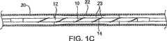
ここで、本発明の実施形態に係る拡張装置10の模式図である図1、図1Aおよび図1Bを参照する。拡張装置10は、インターベンショナル心臓病専門医または放射線科医により一般に用いられるような従来の血管形成バルーンであってもよい拡張バルーン12、および拡張バルーン12上に取り付けまたは装着されたらせん状部または渦巻部14を備える。バルーンと切込形成エレメントのコンプライアンスは、当該組み合わせ構造が病変内で拡張する際、実質的に「ドッグボーニング」にならずにバルーンが確実に均等に拡張するように選択されるべきである。コンプライアンスバルーンまたはセミコンプライアンスバルーンが用いられ、切込形成エレメントのコンプライアンスをバルーンの特性に合わせて適合させていない場合、バルーン−切込形成エレメントシステムの拡張は均等ではない。この不均等性は、切込形成カテーテルの有効性を損なう可能性があり、性能が低下する場合もある。例えば、所与の圧力下では、バルーンの特定の部分は拡張させることができるが、他の部分は切込形成エレメントの過剰な抵抗により拘束される。 Reference is now made to FIGS. 1, 1A and 1B, which are schematic diagrams of an
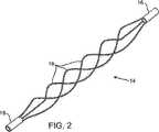
らせん状部14は、代表的には、ニチノールで構成される。らせん状部14は、ステンレス鋼、コバルト−クロム合金、チタン等、他の金属で構成されてもよい。あるいは、渦巻部14は、ポリマー製渦巻線であってもよく、他の弾性材料で構成されてもよい。らせん状部14は、その近位端および遠位端が拡張バルーン12の近位端17および遠位端18に装着されていてもよい。あるいは、渦巻部14は、カラー状アタッチメントエレメント15および16によって拡張バルーン12の遠位端および/または近位端に装着されてもよい。バネまたは他のコンプライアンスエレメントをアタッチメントエレメントの一部として代替的にまたは付加的に設けて、らせん状部が拡張した際にその短縮化に対応するようにしてもよい。 The
拡張装置10は、例えば、従来のカテーテル手順を用いて、血管系から血管20の狭窄物22の領域に挿入される。(「狭窄」という用語は、本明細書中では、例えば、バルーンが拡げるべき血管の狭まった部分である血管病変を意味するために用いられる。)狭窄部位において、拡張バルーン12は、例えば、バルーン内への液体流によって膨張する。らせん状部14は、膨張した拡張バルーン12上で拡がる。図1Bに示すように、拡張バルーン12は、膨張時に、らせん状部14とともに血管20の壁に押し当てられる。 The
次に、拡張バルーン12の収縮後の血管20を示す図1Cを参照する。拡張バルーン12を収縮させると、らせん状部14が縮み、それにより拡張装置10が縮んで、血管20から容易に取り出すことができる。バルーン10の収縮形状は扁平で、概ね円形である。血管20内の狭窄物22は、血管20の壁に押し当てられ、有効な内腔を広げて血流を促進する。らせん状部14を血管20の壁に押し当てることにより、狭窄部位に切込23を入れる。 Reference is now made to FIG. 1C showing the blood vessel 20 after deflation of the dilatation balloon 12. When the dilatation balloon 12 is deflated, the
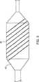
次に、単線24が拡張バルーン12の周囲にらせん状構成で巻かれた切込形成構造を示す図3を参照する。 Reference is now made to FIG. 3, which shows a cut forming structure in which a
他の実施形態では、本発明の切込形成構造は、非らせん状構成を有するようにすることができる。膨張時のバルーン12の直径の増加に対応することができ、バルーンが収縮した際に元の構成に戻ることが可能なデザインの切込形成構造が本発明に有用な適切なデザインである。切込形成エレメントの少なくとも一部は、柔軟性を高め、切込の入れ方を改良するために、バルーンカテーテルの長手軸とは平行にしない。 In other embodiments, the incision forming structure of the present invention can have a non-helical configuration. A suitable notch design useful in the present invention is a notched structure that can accommodate an increase in the diameter of the balloon 12 when inflated and can return to its original configuration when the balloon is deflated. At least a portion of the incision forming element is not parallel to the longitudinal axis of the balloon catheter in order to increase flexibility and improve incision making.
図1A〜図1Cを再度参照して、らせん状部14は、バルーン12の膨張により外側に押され、バルーンの膨張により引き伸ばされる。バルーンが収縮すると、らせん状部14は、その弾性収縮力によりこの収縮を補助する。この能動的収縮は早く、結果として収縮したバルーンは扁平形状になる。バルーン12はらせん状部14内に配置されており、らせん状部は膨張前の形に戻ってバルーンを扁平な円形状にする。 Referring again to FIGS. 1A-1C, the
本発明の他の実施形態では、拡張装置10はステントを有してもよい。ステントは、らせん状部14上にクリンプすることができる。このように、らせん状部14は、病変の固い部位にステントを押し当て、固い石灰化病変の場合でも予め拡張させることなく、血管壁に対して適切にステントを配置することができる。 In other embodiments of the invention, the
次に、本発明の実施形態に係るらせん状部14を示す図2を参照する。らせん状部14は、代表的には、ニチノールで構成される。らせん状部14は、近位端および遠位端がそれぞれカラー15および16に装着された3本のワイヤ19を備える。あるいは、切込形成構造を、スロット付きチューブで構成することができる金属ケージまたはポリマーケージもしくはポリマー製外部エレメントとして形成してもよい。あるいは、切込形成構造は、バルーン材料に直接またはバルーン端部付近に装着した他のエレメントのワイヤを備えてもよい。 Reference is now made to FIG. 2 showing a
ワイヤ19(図2)は、カラー14とカラー15の間に装着される。このワイヤの直径は、代表的には、0.05mm〜0.5mmの範囲である。あるいは、ケージ(例えば、スロット付きチューブで構成された金属ケージ)は、局部応力集中を可能にするいくつかの構成で用いることができる。ケージエレメントの断面サイズおよび断面形状またはワイヤの断面サイズおよび断面形状は変更が可能である。この断面は、円形、矩形、三角形または他の形とすることができる。 The wire 19 (FIG. 2) is attached between the
代替的な実施形態では、ワイヤ19は、バルーン12に装着された小区画を含んでもよい。 In an alternative embodiment, the
本発明のさらに代替的な実施形態では、らせん状部14は、拡張バルーン12の一端または両端に、接着、熱接合または融着するか、機械的に装着してもよい。 In a further alternative embodiment of the present invention, the spiral 14 may be glued, thermally bonded or fused or mechanically attached to one or both ends of the dilatation balloon 12.
さらに他の実施形態では、切込形成構造は、拡張バルーン12にらせん状構成または他の構成で装着されるワイヤを備えてもよい。これらのワイヤは、バルーン12に、熱により装着されるか、接着されるか、または機械的に装着されるなどしてもよい。 In still other embodiments, the incision forming structure may comprise a wire that is attached to the dilatation balloon 12 in a helical or other configuration. These wires may be attached to the balloon 12 by heat, glued, mechanically attached, or the like.
さらに他の実施形態では、切込形成構造は、バルーン12の長手軸に平行ではないため、切込形成構造19とバルーン12の組み合わせが柔軟性を維持するワイヤまたはケージエレメントを備える。 In yet other embodiments, the notch formation structure is not parallel to the longitudinal axis of the balloon 12, so that the combination of the
他の実施形態では、拡張バルーン12と切込形成構造の組み合わせにより病変に切込を入れ、血管壁に対するステントの位置取りを良くしつつ病変内の切込を介して薬剤を拡散させることにより、薬剤を溶出するステントにとって血管をより良好な状態にする。 In another embodiment, the combination of the dilatation balloon 12 and the incision forming structure cuts the lesion and diffuses the drug through the incision in the lesion while improving the positioning of the stent relative to the vessel wall, It makes blood vessels better for stents that elute drugs.
これらの実施形態では、病変の切込により血管壁への薬剤の送達を助長することが可能な場合、薬剤を病変に送達するプラットフォームとしてバルーンを用いることができる。 In these embodiments, a balloon can be used as a platform to deliver the drug to the lesion if the incision of the lesion can facilitate delivery of the drug to the vessel wall.
これらの実施形態では、バルーンを用いて薬剤カプセル、薬剤含有ポリマー等を狭窄物を介して血管壁に埋め込むことにより局部的に薬剤を送達することができる。 In these embodiments, a drug can be locally delivered by embedding a drug capsule, drug-containing polymer, or the like into a blood vessel wall through a stenosis using a balloon.
上記から、本発明がカテーテルおよび切込形成構造を備え、当該切込形成構造がバルーンの上側またはカテーテルの他の拡張可能なシェルの上側に配置されることが分かる。切込形成構造は、バルーンまたは他のシェルに直接装着されてもよく、バルーン材料に埋め込む場合もあるが、より一般的には、バルーンの上側に配置され、バルーンの両側のアタッチメントエレメントを介してカテーテルに装着される個別のケージ構造として形成される。上記拡張可能なケージは、ハイポチューブおよび他の管状構造のレーザー切断、ハイポチューブおよび管のEDM形成、ワイヤおよび他のコンポーネントの溶接等、ステント製造に用いられる技術等の従来の医療機器製造技術を用いて形成してもよい。 From the above, it can be seen that the present invention comprises a catheter and a notch forming structure, which is located on the upper side of the balloon or other expandable shell of the catheter. The incision forming structure may be attached directly to the balloon or other shell and may be embedded in the balloon material, but more commonly is located on the upper side of the balloon and via attachment elements on both sides of the balloon It is formed as a separate cage structure that is attached to the catheter. The expandable cage is a conventional medical device manufacturing technology, such as laser cutting of hypotubes and other tubular structures, EDM formation of hypotubes and tubes, welding of wires and other components, etc. May be used.
代表的には、このような拡張可能なシェル構造は、アタッチメントエレメントおよびそれらアタッチメントエレメント間の中間切込形成部を備える。上記実施形態で例示したように、アタッチメントエレメントは、バルーンまたは他の拡張可能なシェルの両側でカテーテル本体と外接する単純な円形または管構造であってもよい。この単純な管構造は、カテーテル本体上を浮遊した状態、すなわち、未装着であってもよく、あるいはカテーテル本体に固定されていてもよい。アタッチメントエレメントについて、多数の代替的実施形態を下記の実施形態に関連して説明する。 Typically, such an expandable shell structure includes attachment elements and intermediate notch formations between the attachment elements. As illustrated in the above embodiments, the attachment element may be a simple circular or tubular structure circumscribing the catheter body on either side of a balloon or other expandable shell. This simple tube structure may be suspended on the catheter body, i.e., not mounted, or may be fixed to the catheter body. For the attachment element, a number of alternative embodiments are described in connection with the following embodiments.
中間切込形成部はまた、切込形成エレメントの少なくともいくつかが、代表的には、非軸構成に配置される、すなわち、上記拡張可能なケージの軸方向と平行でない方向に配置される種々の構成を有してもよい。中間切込形成部の好適な構成は、一般に、上記実施形態に示すように、1つ以上のらせん状エレメントを備える。他の例示的な構成は、後述する実施形態で示す。 The intermediate incision forming section also includes various in which at least some of the incision forming elements are typically arranged in a non-axial configuration, i.e. in a direction not parallel to the axial direction of the expandable cage. You may have the structure of. Suitable configurations for the intermediate cut forming section generally comprise one or more helical elements as shown in the above embodiments. Other exemplary configurations are shown in the embodiments described below.
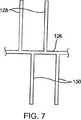
次に、特に図4および図5を参照して、拡張式切込形成ケージ100は、第1および第2のアタッチメントエレメント102および104と、複数の湾曲蛇行部材110を備えた中間切込形成部106とを備える。蛇行部材110は、交互に逆方向に向かって円周状に延びる。これは、図5に示すような蛇行エレメントの「展開」図を見れば理解可能である。第2の代替的な切込形成ケージ構造120を図6〜図8に示す。切込形成ケージ120は、スパイン126により接合された第1および第2のアタッチメントエレメント122および124を備える。複数のC形切込形成エレメント128および130がスパインに装着され、逆向きの円周方向に延びる。このエレメントの形は、図8で見ることができる。上記逆方向は、図7の展開図で見ることができる。 Next, with particular reference to FIGS. 4 and 5, the expandable
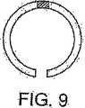
図6〜図8のC形構造の代わりに、種々の異なる円周構造が使用可能であることは言うまでもない。例えば、図9に示すように、一対の対向するC形部分リング構造を用いてもよい。図6のC形構造または図9の二重C形構造はまた、スパイン構造126の上側または下側でバルーンの周囲を一回以上覆うように延ばすことも可能である。 It goes without saying that various different circumferential structures can be used instead of the C-shaped structures of FIGS. For example, as shown in FIG. 9, a pair of opposed C-shaped partial ring structures may be used. The C-shaped structure of FIG. 6 or the double C-shaped structure of FIG. 9 can also be extended to cover the periphery of the balloon one or more times above or below the
拡張式ケージ構造100および120は各々、図1〜図3のバルーン等の拡張バルーン上に、当該拡張バルーンの両側でカテーテル本体に留められたアタッチメントエレメントを用いて取り付けられる。管または円筒状アタッチメントエレメント102、104、122および124は、カテーテル本体上を単に浮遊するようにしてもよい。他の実施形態では、しかしながら、接着剤またはこれらアタッチメントエレメントの一方または両方をカテーテル本体に貼り付ける他の手段を用いることが望ましい場合がある。しかしながら、少なくとも1つの浮遊アタッチメントエレメントを有することが望ましい場合が多く、これは、中間切込形成部が半径方向に拡張する際、当該部分の短縮化に対応することが可能なためである。しかしながら、他の場合には、個々の切込形成エレメントがそのような短縮化に対応するために十分な弾性を有していてもよい。例えば、ニチノールおよび他の形状記憶合金は、代表的には、8%のオーダーの大きな伸縮性を有しており、バルーンの半径方向への拡張により中間切込形成部にかけられた張力への対応には、これで十分な場合もある。 Each of the
次に、図10〜図12を参照して、中間切込形成部を構成する3つのらせん状切込形成エレメント142を備えた拡張式切込形成ケージ140の実施形態について代替的なアタッチメントエレメントを示す。第1のアタッチメントエレメント146は、図11に最適に示す一重蛇行リングを含み、第2のアタッチメントエレメント148は、図12に最適に示す一対の二重蛇行リング150および152を備える。このような蛇行アタッチメント構造の使用は、これら構造の一方または両方を、当該構造の一端または両端を固定するために、カテーテル本体上にクリンプすることができるため有利である。通常、一重蛇行アタッチメント構造48は、カテーテル本体に貼り付けられるが、二段蛇行構造は、切込形成ケージの当該端部の移動を可能にし、下側にあるバルーンの半径方向の拡張に対応するために固定されない。 10-12, an alternative attachment element for an embodiment of an expandable incision forming cage 140 with three helical
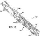
次に、図13および図14を参照して、本発明の切込形成ケージに有用なアタッチメントエレメントのさらに代替的な実施形態を例示する。アタッチメントエレメント180は、一般に図13に示すような一対の蛇行リング182および184を含み、該リング182と184の間に位置するコイルバネ構造186と組み合わせている。コイルバネ構造186は、各々がそれぞれ蛇行リング182および184上にある曲げ構造192および194のうちの一方と接合する3つの入れ子コイルバネ190を備える。バネ構造および隣接する蛇行リングの構造は、図14に示す展開構成を参照することで理解可能である。 Reference is now made to FIGS. 13 and 14 to illustrate further alternative embodiments of attachment elements useful in the incision cage of the present invention.
アタッチメント構造180は、内側リング184を浮遊させたまま最外部リング182を下側のカテーテル本体に固定して装着することができ、らせん状エレメント196を備える中間切込形成部の拡張および収縮に対してはコイルバネ構造186によって対応するため有利である。切込形成ケージがカテーテルに固定されるため、紛失またはバルーンからの滑脱の危険性を低減する一方、十分なコンプライアンスが得られ、中間切込形成部の半径方向の拡張に容易に対応できる。構造180を、切込形成ケージの少なくとも一端、好ましくは両端に装着することにより、ステントと干渉する危険性が低減する。 The
いくつかの実施形態では、図1および図2に示すようなカラー、または図10〜図12に示すようなアタッチメントエレメントは、カラーまたはアタッチメントエレメントをバルーンカテーテル上に取り付けたまま拡張させ、その後カテーテルの直径程度に縮小することを可能にする可撓性材料を含んでもよい。カラーおよび/またはアタッチメントエレメントの拡張性は、ニチノールもしくはポリマー等のコンプライアンス記憶材料または図10〜図12に示すような可撓性蛇行設計の使用により得てもよい。カラーを用いる場合、当該カラーはバルーン上に取り付けられている間は拡張するように成形するかまたは外周にスリット(図示せず)を有するようにしてもよい。あるいは、カラーは、バルーン径への取り付けに対応するように大きくして、その後に切込形成構造をカテーテル本体に留めるためにクリンプしてもよい。 In some embodiments, a collar as shown in FIGS. 1 and 2, or an attachment element as shown in FIGS. 10-12, is allowed to expand while the collar or attachment element remains mounted on the balloon catheter, It may include a flexible material that allows it to be reduced to about the diameter. The expandability of the collar and / or attachment element may be obtained through the use of a compliance memory material such as nitinol or polymer or a flexible serpentine design as shown in FIGS. When a collar is used, the collar may be shaped to expand while attached to the balloon or may have a slit (not shown) on the outer periphery. Alternatively, the collar may be enlarged to accommodate attachment to the balloon diameter and then crimped to secure the incision forming structure to the catheter body.
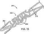
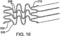
本発明のアタッチメントエレメントのさらに他の実施形態は、図15および図16に示すような軸バネを備える。アタッチメントエレメント200は、末端蛇行リング202と、多数の軸方向蛇行バネエレメント206を備える中間バネ構造204とを備える。蛇行リングエレメント206の性質は、図16の展開構成において見ることができる。任意に、第2の蛇行リング210を、アタッチメント構造200と中間切込形成部212のらせん状切込形成エレメントの間に設けてもよい。 Still another embodiment of the attachment element of the present invention includes an axial spring as shown in FIGS. 15 and 16. The
図13〜図16の実施形態は、半径方向の拡張時の切込形成構造の軸短縮に対応するバネ状エレメント186および204を備える。他の金属および非金属製の軸方向に拡張可能な構造をそのようなアタッチメント構造に使用できることは言うまでもない。例えば、弾性ポリマーチューブの一端を切込形成構造に装着し、他端をカテーテル本体(またはカテーテル本体に固定されるリング、カラーもしくは他の構造)に装着することができる。 The embodiment of FIGS. 13-16 includes spring-
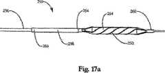
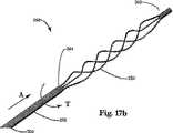
次に、図17aおよび図17bを参照して、軸方向に拡大可能なアタッチメント構造258を有する血管形成カテーテル250のさらなる実施形態を例示する。外部構造252が拡張式拡張バルーン254上に保持され、その一端がカテーテル本体256の遠位端260に固定される。この外部構造は、切込形成構造、切断構造または圧搾構造等、代表的には血管壁からプラーク/血栓を除去するために用いられるいずれの構造を含んでもよい。外部構造252の近位端262は、アタッチメント構造258の遠位端264に接続される。アタッチメント構造258の近位端266は、カテーテル本体256に固定される。後述するように、アタッチメント構造258は、バルーン254の伸縮時に外部構造252およびカテーテル本体256にかかる力を低減するように構成してもよい。 Referring now to FIGS. 17a and 17b, a further embodiment of an angioplasty catheter 250 having an axially expandable attachment structure 258 is illustrated. An
好ましい実施形態では、アタッチメント構造258は、弾性材料で構成された円筒状オーバーチューブまたはコンプライアンスチューブを備える。オーバーチューブ258は、一般に、カテーテル本体256の外径よりも若干大きな内径を有する。アタッチメント構造258の近位端のわずかな部分のみがカテーテル本体に固定されるため、外部構造252に装着された遠位端264は移動が自由であり、カテーテル本体256に対して軸方向および回転方向に自由に摺動する。アタッチメント構造252は、例えば、接着剤により、直接カテーテル本体256および外部構造252、またはカラーもしくは他の中間アタッチメント手段に固定されてもよい。 In a preferred embodiment, the attachment structure 258 comprises a cylindrical overtube or compliance tube made of an elastic material. The overtube 258 generally has an inner diameter that is slightly larger than the outer diameter of the
バルーン254が拡張すると、外部構造252の外周が拡張し、カテーテル本体256に沿って軸方向に収縮し、アタッチメント構造258上に軸方向の力Aが生じる。端部266でカテーテルに固定されたアタッチメント構造258は軸方向に伸び、外部構造252の軸移動に対応する。外部構造252はまた、カテーテル本体256の周囲を回転し、ねじり力Tを引き起こす。アタッチメント構造258の遠位端264は、切込形成構造252の全運動範囲に渡って回転してねじり力Tに対応する一方、近位端266は、カテーテル本体256に対して静止したままである。 When the
図17aおよび図17bに示す構成は、拡張式システムのコンプライアンスを制御することが可能である。一般に、切込形成構造の一端が接続されていない場合、拡張式システムのコンプライアンスは、バルーンと切込形成構造のコンプライアンスを組み合わせたものとなる。しかしながら、図17に示す拡張式システムの端部は遠位端260および近位端266で固定されているため、アタッチメント構造が拡張式システムのコンプライアンスを制御する。 The configuration shown in FIGS. 17a and 17b can control the compliance of the expandable system. In general, when one end of the incision forming structure is not connected, the compliance of the expandable system is a combination of the compliance of the balloon and the incision forming structure. However, because the end of the expandable system shown in FIG. 17 is secured at the
このシステムのコンプライアンスは、オーバーチューブ258の材料選択、肉厚または長さのいずれの組み合わせによっても変更することが可能である。オーバーチューブ258は、ナイロン、ペバックスまたはPETのような弾性ポリマー等、いずれのエラストマーを含んでもよい。代表的には、コンプライアンスチューブ258は、押し出し管で形成されるが、編組ポリマーもしくは金属繊維またはワイヤメッシュを含んでもよい。ニチノールまたはステンレス鋼等の高記憶性金属を用いてもよい。コンプライアンスチューブが押し出しポリマーチューブを備える場合、肉厚を上記の範囲で変更することができ、管長を1cm〜10cmの範囲にすることができる。同じ材料について、管厚がより薄くなり、かつ管長が長くなるにつれて、システムのコンプライアンスはより高くなる。 The compliance of this system can be altered by any combination of material selection, wall thickness or length of the overtube 258. Overtube 258 may include any elastomer, such as an elastic polymer such as nylon, Pebax or PET. Typically, the compliance tube 258 is formed of an extruded tube, but may include braided polymer or metal fiber or wire mesh. High memory metals such as Nitinol or stainless steel may be used. When the compliance tube includes an extruded polymer tube, the wall thickness can be changed in the above range, and the tube length can be in the range of 1 cm to 10 cm. For the same material, the compliance of the system is higher as the tube thickness is reduced and the tube length is increased.
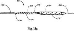
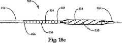
図18a〜cを参照して、血管形成カテーテル300のコンプライアンスも、コンプライアンスチューブ258内に1つ以上の穿孔をあけることにより変更することができる。この穿孔は、チューブの外周の1つ以上のスロットを含んでもよい。このスロットは、コンプライアンスチューブ258の長さに渡って渦巻状に延びる1つの連続的なスロットを備えるか、または任意の数のらせん状312もしくは径方向314等のパターンで配列された多数のスロットであってもよい。これらのスロットはまた、任意の数の円形または矩形等の形状であってもよく、その長さ方向で不連続であったり、コンプライアンスチューブの表面に渡って連続であったりしてもよい。 With reference to FIGS. 18 a-c, compliance of the angioplasty catheter 300 can also be altered by drilling one or more perforations in the compliance tube 258. This perforation may include one or more slots on the outer periphery of the tube. This slot comprises one continuous slot that spirals across the length of the compliance tube 258, or a number of slots arranged in a pattern such as any number of spirals 312 or radial 314. There may be. These slots may also be in any number of shapes, such as circular or rectangular, and may be discontinuous in length or continuous across the surface of the compliance tube.
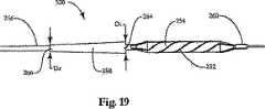
図19を参照して、切込形成カテーテル320の送達および内腔内の処置部位からの回収を容易にするために、コンプライアンスチューブ258の外径を先細り形状にしてもよい。一般に、この外径は、コンプライアンスチューブ258の遠位端264では大きく、コンプライアンスチューブの近位端266では小さくなる。遠位端の外径D1は、切込形成構造およびバルーンが縮小した際の形状に応じて変化するが、その変化は、代表的には、近位端の外径D2よりも0.004インチ〜0.01インチ大きい範囲である。近位端の外径D2は、一般に、コンプライアンスチューブとカテーテルの移行部を滑らかにするために、できる限りカテーテル本体の外径と近くする。一例として、0.033インチの外径を有するカテーテル本体については、コンプライアンスチューブの遠位端がカテーテル本体に対して移動できるようにカテーテル本体との間に隙間を作る0.038インチの内径に対して、遠位端の外径D1は0.042インチすることができる。これに対応して、近位端の外径D2を、内径0.034インチに対して0.0345インチにまで先細りさせて、接着剤でカテーテル本体と接着するために十分な隙間を設ける外径を有したカテーテル本体と密接に合わせてもよい。Referring to FIG. 19, the outer diameter of the compliance tube 258 may be tapered to facilitate delivery of the incision catheter 320 and retrieval from the treatment site within the lumen. Generally, this outer diameter is larger at the
この先細り形状は、コンプライアンスチューブの全長に渡っていてもよく、あるいは、コンプライアンスチューブの長さの一部のみが先細り形状になっていてもよい。先細り形状のコンプライアンスチューブ258は、切込形成構造とカテーテル本体の移行部を滑らかにし、カテーテルの送達または回収時に外管または切込形成構造が内腔壁の一部に引っかかったり、つかえたりする可能性を最小限に抑える。 This tapered shape may extend over the entire length of the compliance tube, or only a portion of the length of the compliance tube may be tapered. The tapered compliance tube 258 smooths the transition between the incision-forming structure and the catheter body, allowing the outer tube or incision-forming structure to be caught or gripped by a portion of the lumen wall during catheter delivery or retrieval Minimize sex.
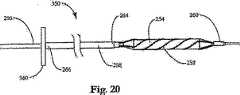
次に、図20を参照して、マニピュレータ360を有する切込形成カテーテル350の代替的な実施形態を示す。アタッチメント構造258は、その遠位端264で切込形成構造252に接続される。カテーテル本体256に直接留める代わりに、近位端266がマニピュレータ360に装着される。代表的には、マニピュレータ360は、カテーテル本体256の近位端に位置し、アタッチメント構造258は、切込形成構造からカテーテル本体の長さに渡って延びる。上記の実施形態と同様に、アタッチメント構造は、シェルが拡張すると、切込形成構造の縮みに対応するために軸方向および回転方向に延びることが可能である。 Referring now to FIG. 20, an alternative embodiment of an incision catheter 350 having a
いくつかの実施形態では、切込形成構造252とバルーン254のコンプライアンスは、半径方向に拡張可能なシェルの伸縮時にマニピュレータを作動させることにより制御される。1つの局面では、アタッチメント構造258は、バルーンが膨張または収縮している際にカテーテル本体256に対して軸方向に進んでもよい。例えば、アタッチメント構造258は、バルーン254がバルーンのコンプライアンスを抑制するように拡張させられている間、カテーテル本体256の遠位端から引き離されてもよい。アタッチメント構造258はまた、バルーンおよび切込形成構造の形状を最小化するためにバルーン254が収縮している最中またはその後にカテーテル本体256の遠位端から引き離されてもよい。あるいは、カテーテル本体256に対してアタッチメント構造258を回転させ、縮小状態から拡張状態への移行中および縮小状態に戻る間、バルーンと切込形成構造のコンプライアンスを制御するためにマニピュレータ360を用いてもよい。 In some embodiments, the compliance of the
次に、図21および図22を参照して、2層積層コンプライアンスチューブ402を有する切込形成ケージ構造400を例示する。図22に示すように、コンプライアンスチューブ402は、少なくともその遠位端410に積層構造404を有する。図22の破線で示すように、この積層構造は、切込形成エレメント406の近位端408を保持する。図22に示すように、切込形成エレメント406は、コンプライアンスチューブ402の外側で当該エレメントを覆う積層板に嵌るような大きさにしてもよい。あるいは、コンプライアンススリーブ管402は、切込形成構造406の内側で、当該エレメント406上に形成された積層(図示せず)と嵌る大きさにしてもよい。 Next, with reference to FIGS. 21 and 22, an
上記積層構造は、コンプライアンスチューブ402と同様のポリマーで構成されてもよく、熱収縮または溶解してコンプライアンススリーブとコンプライアンスチューブを熱接着し、切込形成構造406を挟んでもよい。あるいは、接着剤または超音波もしくはRFエネルギー等の他の接着方法を用いて上記構造を接着してもよい。図21および図22に示すような積層構造は、切込形成ケージとアタッチメント構造の移行部を滑らかにし、それらの接着を強化する。このような滑らかな移行部は、切込形成ケージを脈管構造から抜き取る際に特に有利である。 The laminated structure may be made of the same polymer as the
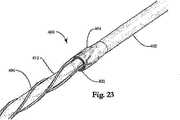
図23および図24は、拡張式拡張バルーン412上に位置する切込形成ケージ400を示す。図24に示すように、切込形成構造の遠位端418は、エンドキャップ416によりカテーテル本体の遠位先端414と結合させてもよい。エンドキャップ416は、適合性ポリマーで構成し、カテーテル本体と熱接合させて切込形成構造の遠位端418をカテーテル本体に固定してもよい。 23 and 24 show the
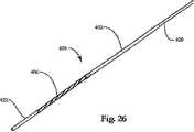
次に、図25〜図27を参照して、拡張式切込形成ケージ406をバルーンカテーテル上に取り付ける方法を例示する。切込形成ケージ406を、バルーン412の外径よりも若干大きな内径を有する挿入管422上に取り付けて予め拡張させる。次に、バルーン412を有するカテーテル本体420を挿入管422の内径に挿入し、図26に示すように、バルーン412が切込形成構造406に対して適切な位置につくまで進める。次いで、図27に示すように、拡張した切込形成構造がバルーン412およびカテーテル本体420上で縮小するように挿入管422を引き戻す。次いで、切込形成構造406の遠位端418をカテーテル本体420の遠位先端414に留めて、その切込形成構造/アタッチメント構造アセンブリの近位端424をカテーテル本体420の中間位置に留めてもよい。 Next, with reference to FIGS. 25-27, a method of mounting the
当業者は、本発明が特に上記記載事項に限定されないことを理解する。本発明の範囲に該当する代替的な実施形態が予期される。 The person skilled in the art understands that the present invention is not particularly limited to the above description. Alternative embodiments are contemplated that fall within the scope of the invention.
Claims (8)
Translated fromJapanese近位端および遠位端を有するカテーテル本体と、
前記カテーテル本体の前記遠位端近傍で半径方向に拡張可能なシェルと、
前記シェル上に載せられるが前記シェルに装着されていない外部構造であって、前記外部構造は、その遠位端において、前記カテーテル本体に装着され、前記シェルが半径方向に拡張した際に、軸方向に縮まる、および/または、前記カテーテル本体に対して回転する、外部構造と、
前記カテーテル本体に固定して装着された近位端と前記外部構造の前記近位端に装着された遠位端とを有するアタッチメント構造であって、前記アタッチメント構造は、前記外部構造が前記シェルによって拡張させられた際に生じた寸法形状の変化および反力に対応するために十分な大きさとコンプライアンスを有する、アタッチメント構造と、
を備える、カテーテル。An angioplasty catheter,
A catheter body having a proximal end and a distal end;
A radially expandable shell near the distal end of the catheter body;
An external structure in which the rests on the shell is not mounted ontheshell, wherein the outer structure includes at its distal end, is attached to the catheter body, when said shell is expanded radially, the axial An external structure that shrinks in a direction and / or rotates relative to the catheter body;
A attachment structure havinga distalend, wherein mounted on theproximal end of the outer structureand a proximal endthat is fixedly attached to the catheter body,wherein the attachment structure, bythe outer structure is the shell An attachment structure having sufficient size and compliance to accommodate dimensional changes and reaction forces that occur when expanded;
A catheter.
Applications Claiming Priority (5)
| Application Number | Priority Date | Filing Date | Title |
|---|---|---|---|
| US10/810,330US7955350B2 (en) | 2003-01-21 | 2004-03-25 | Apparatus and methods for treating hardened vascular lesions |
| US10/810,330 | 2004-03-25 | ||
| US10/917,917US8080026B2 (en) | 2003-01-21 | 2004-08-13 | Apparatus and methods for treating hardened vascular lesions |
| US10/917,917 | 2004-08-13 | ||
| PCT/US2005/009571WO2005094477A2 (en) | 2004-03-25 | 2005-03-21 | Apparatus and methods for treating hardened vascular lesions |
Publications (3)
| Publication Number | Publication Date |
|---|---|
| JP2007530158A JP2007530158A (en) | 2007-11-01 |
| JP2007530158A5 JP2007530158A5 (en) | 2008-04-24 |
| JP4839307B2true JP4839307B2 (en) | 2011-12-21 |
Family
ID=35064384
Family Applications (1)
| Application Number | Title | Priority Date | Filing Date |
|---|---|---|---|
| JP2007505113AExpired - LifetimeJP4839307B2 (en) | 2004-03-25 | 2005-03-21 | Apparatus and method for treating hardened vascular lesions |
Country Status (4)
| Country | Link |
|---|---|
| US (5) | US8080026B2 (en) |
| EP (1) | EP1740105B1 (en) |
| JP (1) | JP4839307B2 (en) |
| WO (1) | WO2005094477A2 (en) |
Families Citing this family (120)
| Publication number | Priority date | Publication date | Assignee | Title |
|---|---|---|---|---|
| CN100502806C (en) | 2001-11-09 | 2009-06-24 | 诺沃斯特公司 | Balloon catheter with non-deployable stent |
| US20040111108A1 (en) | 2001-11-09 | 2004-06-10 | Farnan Robert C. | Balloon catheter with non-deployable stent |
| US8080026B2 (en)* | 2003-01-21 | 2011-12-20 | Angioscore, Inc. | Apparatus and methods for treating hardened vascular lesions |
| US7131981B2 (en)* | 2003-03-25 | 2006-11-07 | Angiodynamics, Inc. | Device and method for converting a balloon catheter into a cutting balloon catheter |
| US7771447B2 (en)* | 2003-12-19 | 2010-08-10 | Boston Scientific Scimed, Inc. | Balloon refolding device |
| US20050240148A1 (en)* | 2004-04-21 | 2005-10-27 | Scimed Life Systems, Inc. | Traction cutting balloon |
| US7976557B2 (en)* | 2004-06-23 | 2011-07-12 | Boston Scientific Scimed, Inc. | Cutting balloon and process |
| JP4940398B2 (en)* | 2004-12-30 | 2012-05-30 | クック メディカル テクノロジーズ エルエルシー | Catheter assembly with plaque cutting balloon |
| US20060178685A1 (en)* | 2004-12-30 | 2006-08-10 | Cook Incorporated | Balloon expandable plaque cutting device |
| US20060173487A1 (en)* | 2005-01-05 | 2006-08-03 | Cook Incorporated | Angioplasty cutting device and method for treating a stenotic lesion in a body vessel |
| US8465509B2 (en)* | 2005-02-28 | 2013-06-18 | Avraham Shekalim | Apparatus and method for removing deposits from tubular structure, particularly atheroma from blood vessels |
| US10076641B2 (en) | 2005-05-11 | 2018-09-18 | The Spectranetics Corporation | Methods and systems for delivering substances into luminal walls |
| US7708753B2 (en) | 2005-09-27 | 2010-05-04 | Cook Incorporated | Balloon catheter with extendable dilation wire |
| US20090281387A1 (en)* | 2005-10-05 | 2009-11-12 | Olympus Medical Systems Corp. | Capsule-type medical apparatus, guidance system and guidance method therefor, and intrasubject insertion apparatus |
| WO2007053728A1 (en)* | 2005-11-01 | 2007-05-10 | Cook Incorporated | Angioplasty cutting device and method |
| US8388573B1 (en) | 2006-06-28 | 2013-03-05 | Abbott Cardiovascular Systems Inc. | Local delivery with a balloon covered by a cage |
| AU2007231733B2 (en)* | 2006-11-28 | 2014-03-13 | Cathrx Ltd | A catheter steering system |
| US20080228139A1 (en) | 2007-02-06 | 2008-09-18 | Cook Incorporated | Angioplasty Balloon With Concealed Wires |
| US8323307B2 (en) | 2007-02-13 | 2012-12-04 | Cook Medical Technologies Llc | Balloon catheter with dilating elements |
| US20080300610A1 (en) | 2007-05-31 | 2008-12-04 | Cook Incorporated | Device for treating hardened lesions and method of use thereof |
| US20090171284A1 (en)* | 2007-12-27 | 2009-07-02 | Cook Incorporated | Dilation system |
| US20090171283A1 (en)* | 2007-12-27 | 2009-07-02 | Cook Incorporated | Method of bonding a dilation element to a surface of an angioplasty balloon |
| WO2009114425A1 (en) | 2008-03-13 | 2009-09-17 | Cook Incorporated | Cutting balloon with connector and dilation element |
| AU2009256738C1 (en)* | 2008-06-10 | 2013-08-01 | Bavaria Medizin Technologie Gmbh | Scoring catheter for treating diseased heart valves |
| US20100010521A1 (en)* | 2008-07-10 | 2010-01-14 | Cook Incorporated | Cutting balloon with movable member |
| EP2172242A1 (en)* | 2008-10-03 | 2010-04-07 | National University of Ireland Galway | Intravascular Treatment Device |
| US20100286593A1 (en)* | 2009-05-11 | 2010-11-11 | Hotspur Technologies, Inc. | Balloon catheter with cutting features and methods for use |
| CN102740807B (en) | 2009-11-30 | 2015-11-25 | 恩多斯潘有限公司 | Multi-component stent-graft system for implantation into vessels with multiple branches |
| GB0921236D0 (en)* | 2009-12-03 | 2010-01-20 | Angiomed Ag | Stent device delivery system and method of making such |
| GB0921240D0 (en)* | 2009-12-03 | 2010-01-20 | Angiomed Ag | Stent device delivery system and method of making such |
| US8348987B2 (en)* | 2009-12-22 | 2013-01-08 | Cook Medical Technologies Llc | Balloon with scoring member |
| US9468517B2 (en)* | 2010-02-08 | 2016-10-18 | Endospan Ltd. | Thermal energy application for prevention and management of endoleaks in stent-grafts |
| US9199066B2 (en) | 2010-03-12 | 2015-12-01 | Quattro Vascular Pte Ltd. | Device and method for compartmental vessel treatment |
| EP2380604A1 (en) | 2010-04-19 | 2011-10-26 | InnoRa Gmbh | Improved coating formulations for scoring or cutting balloon catheters |
| US8632559B2 (en)* | 2010-09-21 | 2014-01-21 | Angioscore, Inc. | Method and system for treating valve stenosis |
| US8685049B2 (en) | 2010-11-18 | 2014-04-01 | Rex Medical L.P. | Cutting wire assembly for use with a catheter |
| US8685050B2 (en) | 2010-10-06 | 2014-04-01 | Rex Medical L.P. | Cutting wire assembly for use with a catheter |
| US9282991B2 (en) | 2010-10-06 | 2016-03-15 | Rex Medical, L.P. | Cutting wire assembly with coating for use with a catheter |
| DE102010051740A1 (en)* | 2010-11-19 | 2012-05-24 | Phenox Gmbh | thrombectomy |
| US8702736B2 (en) | 2010-11-22 | 2014-04-22 | Rex Medical L.P. | Cutting wire assembly for use with a catheter |
| GB2485769B (en)* | 2010-11-22 | 2012-12-05 | Cook Medical Technologies Llc | Scoring balloon and method of making same |
| CA2826022A1 (en) | 2011-02-03 | 2012-08-09 | Endospan Ltd. | Implantable medical devices constructed of shape memory material |
| WO2012117395A1 (en) | 2011-03-02 | 2012-09-07 | Endospan Ltd. | Reduced-strain extra- vascular ring for treating aortic aneurysm |
| US9095370B2 (en)* | 2011-06-29 | 2015-08-04 | Cordis Corporation | System and method for dilating and adjusting flexibility in a guiding device |
| US9254209B2 (en) | 2011-07-07 | 2016-02-09 | Endospan Ltd. | Stent fixation with reduced plastic deformation |
| WO2013023121A1 (en) | 2011-08-11 | 2013-02-14 | Boston Scientific Scimed, Inc. | Expandable scaffold with cutting elements mounted thereto |
| US9839510B2 (en) | 2011-08-28 | 2017-12-12 | Endospan Ltd. | Stent-grafts with post-deployment variable radial displacement |
| US10610255B2 (en) | 2011-09-13 | 2020-04-07 | John P. Pigott | Intravascular catheter having an expandable incising portion and medication delivery system |
| US12324603B2 (en) | 2011-09-13 | 2025-06-10 | Venturemed Group, Inc. | Intravascular catheter having an expandable incising portion |
| EP2755714B1 (en) | 2011-09-13 | 2020-03-11 | Pigott, John, P. | Intravascular catheter having an expandable incising portion |
| US11559325B2 (en) | 2011-09-13 | 2023-01-24 | Venturemed Group, Inc. | Intravascular catheter having an expandable incising portion and grating tool |
| US10463387B2 (en) | 2011-09-13 | 2019-11-05 | John P. Pigott | Intravascular catheter having an expandable incising portion for incising atherosclerotic material located in a blood vessel |
| US11413062B2 (en) | 2011-09-13 | 2022-08-16 | Venturemed Group, Inc. | Methods for preparing a zone of attention within a vascular system for subsequent angioplasty with an intravascular catheter device having an expandable incising portion and an integrated embolic protection device |
| US11357533B2 (en) | 2011-09-13 | 2022-06-14 | Venturemed Group, Inc. | Intravascular catheter having an expandable incising portion and abrasive surfaces |
| US9427339B2 (en) | 2011-10-30 | 2016-08-30 | Endospan Ltd. | Triple-collar stent-graft |
| US9364255B2 (en) | 2011-11-09 | 2016-06-14 | Boston Scientific Scimed, Inc. | Medical cutting devices and methods of use |
| DE102011120004B3 (en)* | 2011-11-30 | 2013-03-14 | Universitätsklinikum Freiburg | Device for detaching wall-shaped thrombi from a body vessel |
| SG11201403991RA (en) | 2012-02-01 | 2014-09-26 | Quattro Vascular Pte Ltd | Device for compartmental dilatation of blood vessels |
| US9216033B2 (en) | 2012-02-08 | 2015-12-22 | Quattro Vascular Pte Ltd. | System and method for treating biological vessels |
| CN104168859B (en) | 2012-02-08 | 2016-06-29 | 夸超脉管私人有限公司 | There is the restraining structure of non-linear axial pillar |
| CN104936550B (en) | 2012-11-15 | 2017-09-22 | 恩菲纽姆血管技术有限公司 | Temporary vascular scaffolds and scoring devices |
| US9993360B2 (en) | 2013-01-08 | 2018-06-12 | Endospan Ltd. | Minimization of stent-graft migration during implantation |
| KR101917918B1 (en)* | 2013-02-22 | 2018-11-12 | 뉴로바스크 테크놀로지스, 아이엔씨. | Blood flow restriction apparatus and method for embolus removal in human vasculature |
| US9668892B2 (en) | 2013-03-11 | 2017-06-06 | Endospan Ltd. | Multi-component stent-graft system for aortic dissections |
| US10842567B2 (en) | 2013-03-13 | 2020-11-24 | The Spectranetics Corporation | Laser-induced fluid filled balloon catheter |
| US9320530B2 (en)* | 2013-03-13 | 2016-04-26 | The Spectranetics Corporation | Assisted cutting balloon |
| US20140309672A1 (en)* | 2013-03-15 | 2014-10-16 | Cook Medical Technologies Llc | Clot buster aspiration catheter |
| US9808276B2 (en)* | 2013-04-25 | 2017-11-07 | Invatec S.P.A. | Angioplasty balloon having selectively deployable cutting or scoring element and related methods |
| US10828471B2 (en) | 2013-07-15 | 2020-11-10 | John P. Pigott | Balloon catheter having a retractable sheath |
| US10130798B2 (en) | 2013-07-15 | 2018-11-20 | John P. Pigott | Balloon catheter having a retractable sheath and locking mechanism |
| US11202892B2 (en) | 2013-07-15 | 2021-12-21 | John P. Pigott | Balloon catheter having a retractable sheath |
| US10315014B2 (en) | 2013-07-15 | 2019-06-11 | John P. Pigott | Balloon catheter having a retractable sheath and locking mechanism with balloon recapture element |
| US10117668B2 (en)* | 2013-10-08 | 2018-11-06 | The Spectranetics Corporation | Balloon catheter with non-deployable stent having improved stability |
| EP3127497B1 (en)* | 2013-11-07 | 2018-01-31 | Cook Medical Technologies LLC | Balloon catheter with lithotripsy amplification system |
| US10201685B2 (en) | 2013-11-13 | 2019-02-12 | West Coast Catheter, Inc. | High-pressure balloons |
| US9149612B2 (en) | 2013-11-13 | 2015-10-06 | West Coast Catheter, Inc. | Flexible high-pressure balloons |
| US9782571B2 (en) | 2014-01-30 | 2017-10-10 | Chuter A. M. Timothy | Flexible high-pressure angioplasty balloons |
| AU2014349155B2 (en)* | 2013-11-13 | 2019-10-03 | Chuter, Timothy A. M. | Flexible high-pressure balloons |
| WO2015075708A1 (en) | 2013-11-19 | 2015-05-28 | Endospan Ltd. | Stent system with radial-expansion locking |
| US10286190B2 (en) | 2013-12-11 | 2019-05-14 | Cook Medical Technologies Llc | Balloon catheter with dynamic vessel engaging member |
| EP2898920B1 (en) | 2014-01-24 | 2018-06-06 | Cook Medical Technologies LLC | Articulating balloon catheter |
| US9724121B2 (en) | 2014-02-02 | 2017-08-08 | TriReme Medical, LLC | Apparatus and methods for recannalization, valve repair and replacement |
| US9943322B2 (en)* | 2014-07-09 | 2018-04-17 | Boston Scientific Scimed, Inc. | Medical retrieval devices and methods |
| USD868253S1 (en) | 2014-10-13 | 2019-11-26 | Boston Scientific Scimed, Inc. | Macerator wire |
| WO2016079649A1 (en) | 2014-11-17 | 2016-05-26 | Quattro Vascular Pte Ltd. | Balloon catheter system |
| EP3226783B1 (en) | 2014-12-03 | 2024-01-10 | PAVmed Inc. | Systems for percutaneous division of fibrous structures |
| CN106029005B (en) | 2014-12-18 | 2018-01-19 | 恩都思潘有限公司 | The Endovascular stent-graft of horizontal conduit with tired resistance |
| EP3240603B1 (en) | 2014-12-30 | 2019-05-01 | The Spectranetics Corporation | Laser-induced fluid filled balloon catheter |
| WO2016109739A1 (en) | 2014-12-30 | 2016-07-07 | The Spectranetics Corporation | Electrically-induced pressure wave emitting catheter sheath |
| US11058492B2 (en) | 2014-12-30 | 2021-07-13 | The Spectranetics Corporation | Laser-induced pressure wave emitting catheter sheath |
| EP3244815B1 (en) | 2015-01-13 | 2020-04-22 | Pigott, John, P. | Intravascular catheter having an expandable portion |
| US10603069B2 (en) | 2015-01-13 | 2020-03-31 | John P. Pigott | Intravascular catheter balloon device having a tool for atherectomy or an incising portion for atheromatous plaque scoring |
| EP3072463B1 (en)* | 2015-03-25 | 2022-08-17 | B. Braun Melsungen AG | Medical kit or set for treating a diseased hollow organ |
| US10182841B1 (en)* | 2015-06-16 | 2019-01-22 | C.R. Bard, Inc. | Medical balloon with enhanced focused force control |
| US10299823B2 (en)* | 2015-10-20 | 2019-05-28 | Medtronic Vascular, Inc. | Scoring balloon catheter |
| US11969567B2 (en) | 2015-11-18 | 2024-04-30 | Spectranetics Llc | Balloon angioplasty catheter coating to encourage vessel repair and further reduce restenosis |
| US20180104458A1 (en)* | 2016-10-17 | 2018-04-19 | Cook Medical Technologies Llc | Shape controlled balloon catheter |
| ES2831026T3 (en) | 2017-02-24 | 2021-06-07 | Venturemed Group Inc | Intravascular catheter that has an expandable incision portion and abrasive surfaces |
| EP4018946A1 (en) | 2017-05-03 | 2022-06-29 | Medtronic Vascular, Inc. | Tissue-removing catheter |
| US11690645B2 (en) | 2017-05-03 | 2023-07-04 | Medtronic Vascular, Inc. | Tissue-removing catheter |
| JP7167020B2 (en)* | 2017-06-23 | 2022-11-08 | 株式会社グッドマン | balloon catheter |
| US11490923B2 (en) | 2018-01-05 | 2022-11-08 | Cook Medical Technologies Llc | Device with sharp and blunt regions for removing occlusions |
| EP4295892B1 (en) | 2018-04-09 | 2025-08-20 | Boston Scientific Scimed, Inc. | Cutting balloon catheter |
| CN108577937B (en)* | 2018-05-18 | 2020-09-18 | 鼎科医疗技术(苏州)有限公司 | Cutting balloon and balloon catheter |
| JP2022500190A (en)* | 2018-09-22 | 2022-01-04 | トランジット サイエンティフィック,エルエルシー | Expandable exoskeleton device for delivering medicinal products |
| CN118697424A (en) | 2018-11-16 | 2024-09-27 | 美敦力瓦斯科尔勒公司 | Tissue Removal Catheter |
| US11819236B2 (en) | 2019-05-17 | 2023-11-21 | Medtronic Vascular, Inc. | Tissue-removing catheter |
| CN110339464B (en)* | 2019-08-14 | 2022-05-10 | 北京弘海科技发展有限公司 | Balloon catheter with metal sheath and processing method of metal sheath |
| WO2021127609A1 (en) | 2019-12-20 | 2021-06-24 | Surmodics, Inc. | Universal scoring device |
| US12011184B2 (en) | 2020-02-10 | 2024-06-18 | Elixir Medical Corporation | Methods and apparatus for plaque disruption |
| US12114885B2 (en)* | 2020-04-30 | 2024-10-15 | Brosmed Medical Co., Ltd. | Cutting device and cutting balloon |
| US12156693B2 (en) | 2020-05-27 | 2024-12-03 | PAVmed Inc. | Systems and methods for minimally-invasive division of fibrous structures |
| US20230190328A1 (en)* | 2020-06-12 | 2023-06-22 | C.R. Bard, Inc. | Balloon catheter with selective scoring function |
| JP2023159897A (en)* | 2020-09-04 | 2023-11-02 | テルモ株式会社 | medical device |
| US20250228581A1 (en)* | 2021-10-11 | 2025-07-17 | Bard Peripheral Vascular, Inc. | Endovascular thrombus scraper and related methods |
| CN114098902B (en)* | 2021-12-02 | 2023-12-15 | 山东吉威医疗制品有限公司 | Silk knife and sacculus device |
| CN116328153A (en)* | 2021-12-24 | 2023-06-27 | 上海博畅医疗科技有限公司 | balloon catheter |
| US12408932B2 (en) | 2022-03-23 | 2025-09-09 | Venturemed Group, Inc. | Intravascular device having feedback elements |
| US20240149020A1 (en) | 2022-11-04 | 2024-05-09 | Controlled Delivery Systems, Inc. | Catheters for the aspiration controlled delivery of closure agents |
| EP4611658A1 (en) | 2022-11-04 | 2025-09-10 | Solvein Inc. | Catheters and related methods for aspiration and controlled delivery of closure agents |
Family Cites Families (367)
| Publication number | Priority date | Publication date | Assignee | Title |
|---|---|---|---|---|
| US10487A (en)* | 1854-01-31 | Chtjkbt | ||
| US2701559A (en) | 1951-08-02 | 1955-02-08 | William A Cooper | Apparatus for exfoliating and collecting diagnostic material from inner walls of hollow viscera |
| US2854983A (en) | 1957-10-31 | 1958-10-07 | Arnold M Baskin | Inflatable catheter |
| US3045677A (en) | 1960-05-03 | 1962-07-24 | American Cystoscope Makers Inc | Inflatable balloon catheter |
| US3467101A (en) | 1965-09-30 | 1969-09-16 | Edwards Lab Inc | Balloon catheter |
| US3825013A (en) | 1973-03-12 | 1974-07-23 | Mcm Hospital Supplies Inc | Balloon catheter |
| US4327736A (en) | 1979-11-20 | 1982-05-04 | Kanji Inoue | Balloon catheter |
| US4483340A (en) | 1980-10-20 | 1984-11-20 | Thomas J. Fogarty | Dilatation catheter |
| US4456011A (en) | 1980-12-22 | 1984-06-26 | Irene Warnecke | Balloon-catheter |
| US4604762A (en) | 1981-02-13 | 1986-08-12 | Thoratec Laboratories Corporation | Arterial graft prosthesis |
| US4637396A (en) | 1984-10-26 | 1987-01-20 | Cook, Incorporated | Balloon catheter |
| US4737589A (en) | 1985-08-27 | 1988-04-12 | Nippon Kayaku Kabushiki Kaisha | Platinum Complexes |
| CH659166GA3 (en) | 1985-10-07 | 1987-01-15 | ||
| US4733665C2 (en) | 1985-11-07 | 2002-01-29 | Expandable Grafts Partnership | Expandable intraluminal graft and method and apparatus for implanting an expandable intraluminal graft |
| US5102417A (en) | 1985-11-07 | 1992-04-07 | Expandable Grafts Partnership | Expandable intraluminal graft, and method and apparatus for implanting an expandable intraluminal graft |
| US4649922A (en) | 1986-01-23 | 1987-03-17 | Wiktor Donimik M | Catheter arrangement having a variable diameter tip and spring prosthesis |
| US5350395A (en) | 1986-04-15 | 1994-09-27 | Yock Paul G | Angioplasty apparatus facilitating rapid exchanges |
| US4723549A (en) | 1986-09-18 | 1988-02-09 | Wholey Mark H | Method and apparatus for dilating blood vessels |
| US4838853A (en) | 1987-02-05 | 1989-06-13 | Interventional Technologies Inc. | Apparatus for trimming meniscus |
| US4796629A (en) | 1987-06-03 | 1989-01-10 | Joseph Grayzel | Stiffened dilation balloon catheter device |
| US4969458A (en) | 1987-07-06 | 1990-11-13 | Medtronic, Inc. | Intracoronary stent and method of simultaneous angioplasty and stent implant |
| US5133732A (en) | 1987-10-19 | 1992-07-28 | Medtronic, Inc. | Intravascular stent |
| US4942788A (en) | 1987-11-23 | 1990-07-24 | Interventional Technologies, Inc. | Method of manufacturing a cutter for atherectomy device |
| US4887613A (en) | 1987-11-23 | 1989-12-19 | Interventional Technologies Inc. | Cutter for atherectomy device |
| US4895166A (en) | 1987-11-23 | 1990-01-23 | Interventional Technologies, Inc. | Rotatable cutter for the lumen of a blood vesel |
| FR2624747A1 (en) | 1987-12-18 | 1989-06-23 | Delsanti Gerard | REMOVABLE ENDO-ARTERIAL DEVICES FOR REPAIRING ARTERIAL WALL DECOLLEMENTS |
| US5423745A (en) | 1988-04-28 | 1995-06-13 | Research Medical, Inc. | Irregular surface balloon catheters for body passageways and methods of use |
| US4921484A (en) | 1988-07-25 | 1990-05-01 | Cordis Corporation | Mesh balloon catheter device |
| DE68912713T2 (en) | 1988-10-28 | 1994-05-19 | Kanji Inoue | Balloon catheter. |
| US5904679A (en) | 1989-01-18 | 1999-05-18 | Applied Medical Resources Corporation | Catheter with electrosurgical cutter |
| US5779698A (en) | 1989-01-18 | 1998-07-14 | Applied Medical Resources Corporation | Angioplasty catheter system and method for making same |
| US5628746A (en) | 1989-01-18 | 1997-05-13 | Applied Medical Resources Corporation | Dilatation catheter assembly with cutting element and method of using the same |
| US4950277A (en) | 1989-01-23 | 1990-08-21 | Interventional Technologies, Inc. | Atherectomy cutting device with eccentric wire and method |
| US4966604A (en) | 1989-01-23 | 1990-10-30 | Interventional Technologies Inc. | Expandable atherectomy cutter with flexibly bowed blades |
| US4986807A (en) | 1989-01-23 | 1991-01-22 | Interventional Technologies, Inc. | Atherectomy cutter with radially projecting blade |
| ES2049204T3 (en) | 1989-01-30 | 1994-07-16 | Bard Inc C R | RAPIDLY CHANGEABLE CORONARY CATHETER. |
| US4976711A (en) | 1989-04-13 | 1990-12-11 | Everest Medical Corporation | Ablation catheter with selectively deployable electrodes |
| US5116318A (en) | 1989-06-06 | 1992-05-26 | Cordis Corporation | Dilatation balloon within an elastic sleeve |
| WO1991002494A1 (en) | 1989-08-18 | 1991-03-07 | Evi Corporation | Catheter atherotome |
| US5263963A (en) | 1989-09-08 | 1993-11-23 | Advanced Cardiovascular Systems, Inc. | Expandable cage catheter for repairing a damaged blood vessel |
| US4986830A (en) | 1989-09-22 | 1991-01-22 | Schneider (U.S.A.) Inc. | Valvuloplasty catheter with balloon which remains stable during inflation |
| US5062648A (en) | 1989-09-26 | 1991-11-05 | Interventional Technologies, Inc. | Seal for rotating torque tube with seal valve |
| US5026384A (en) | 1989-11-07 | 1991-06-25 | Interventional Technologies, Inc. | Atherectomy systems and methods |
| US5019088A (en) | 1989-11-07 | 1991-05-28 | Interventional Technologies Inc. | Ovoid atherectomy cutter |
| US5062384A (en) | 1989-11-13 | 1991-11-05 | Mfm Technology, Inc. | Vacuum chuck rotary seal |
| US5019089A (en) | 1989-12-07 | 1991-05-28 | Interventional Technologies Inc. | Atherectomy advancing probe and method of use |
| US5304121A (en) | 1990-12-28 | 1994-04-19 | Boston Scientific Corporation | Drug delivery system making use of a hydrogel polymer coating |
| US5674192A (en) | 1990-12-28 | 1997-10-07 | Boston Scientific Corporation | Drug delivery |
| US5003918A (en) | 1989-12-28 | 1991-04-02 | Interventional Technologies, Inc. | Apparatus for manufacturing atherectomy torque tubes |
| US5108416A (en) | 1990-02-13 | 1992-04-28 | C. R. Bard, Inc. | Stent introducer system |
| US5221261A (en) | 1990-04-12 | 1993-06-22 | Schneider (Usa) Inc. | Radially expandable fixation member |
| US5071407A (en) | 1990-04-12 | 1991-12-10 | Schneider (U.S.A.) Inc. | Radially expandable fixation member |
| US5342301A (en)* | 1992-08-13 | 1994-08-30 | Advanced Polymers Incorporated | Multi-lumen balloons and catheters made therewith |
| US5624392A (en) | 1990-05-11 | 1997-04-29 | Saab; Mark A. | Heat transfer catheters and methods of making and using same |
| US5120322A (en) | 1990-06-13 | 1992-06-09 | Lathrotec, Inc. | Method and apparatus for treatment of fibrotic lesions |
| US5320634A (en) | 1990-07-03 | 1994-06-14 | Interventional Technologies, Inc. | Balloon catheter with seated cutting edges |
| US5196024A (en) | 1990-07-03 | 1993-03-23 | Cedars-Sinai Medical Center | Balloon catheter with cutting edge |
| US5101682A (en) | 1990-07-06 | 1992-04-07 | Interventional Technologies, Inc. | Reinforced tubing |
| US5098440A (en) | 1990-08-14 | 1992-03-24 | Cordis Corporation | Object retrieval method and apparatus |
| US5100423A (en) | 1990-08-21 | 1992-03-31 | Medical Engineering & Development Institute, Inc. | Ablation catheter |
| US5222971A (en) | 1990-10-09 | 1993-06-29 | Scimed Life Systems, Inc. | Temporary stent and methods for use and manufacture |
| US5449372A (en) | 1990-10-09 | 1995-09-12 | Scimed Lifesystems, Inc. | Temporary stent and methods for use and manufacture |
| US5350101A (en) | 1990-11-20 | 1994-09-27 | Interventional Technologies Inc. | Device for advancing a rotatable tube |
| US5112345A (en) | 1990-12-17 | 1992-05-12 | Interventional Technologies | Atherectomy cutter with arcuate blades |
| US5102402A (en) | 1991-01-04 | 1992-04-07 | Medtronic, Inc. | Releasable coatings on balloon catheters |
| US5295958A (en) | 1991-04-04 | 1994-03-22 | Shturman Cardiology Systems, Inc. | Method and apparatus for in vivo heart valve decalcification |
| US5181911A (en) | 1991-04-22 | 1993-01-26 | Shturman Technologies, Inc. | Helical balloon perfusion angioplasty catheter |
| US5190058A (en) | 1991-05-22 | 1993-03-02 | Medtronic, Inc. | Method of using a temporary stent catheter |
| US5458568A (en) | 1991-05-24 | 1995-10-17 | Cortrak Medical, Inc. | Porous balloon for selective dilatation and drug delivery |
| US5217474A (en) | 1991-07-15 | 1993-06-08 | Zacca Nadim M | Expandable tip atherectomy method and apparatus |
| ATE191325T1 (en) | 1991-07-15 | 2000-04-15 | Nadim M Zacca | ARTERY REMOVAL AND ANGIOPLASTY DEVICE |
| CA2079417C (en) | 1991-10-28 | 2003-01-07 | Lilip Lau | Expandable stents and method of making same |
| EP0549100A1 (en) | 1991-12-20 | 1993-06-30 | Interventional Technologies Inc | Catheter balloon formed from a polymeric composite |
| US5224949A (en) | 1992-01-13 | 1993-07-06 | Interventional Technologies, Inc. | Camming device |
| US5192291A (en) | 1992-01-13 | 1993-03-09 | Interventional Technologies, Inc. | Rotationally expandable atherectomy cutter assembly |
| US5742019A (en) | 1992-01-13 | 1998-04-21 | Interventional Technologies Inc. | Method for manufacturing an atherectomy cutter having a positive angle of attack |
| US5224945A (en) | 1992-01-13 | 1993-07-06 | Interventional Technologies, Inc. | Compressible/expandable atherectomy cutter |
| US5209727A (en) | 1992-01-29 | 1993-05-11 | Interventional Technologies, Inc. | Guide wire with integral angioplasty balloon |
| US5226887A (en) | 1992-02-07 | 1993-07-13 | Interventional Technologies, Inc. | Collapsible folding angioplasty balloon |
| US5295959A (en) | 1992-03-13 | 1994-03-22 | Medtronic, Inc. | Autoperfusion dilatation catheter having a bonded channel |
| US5295493A (en) | 1992-03-19 | 1994-03-22 | Interventional Technologies, Inc. | Anatomical guide wire |
| US5282823A (en) | 1992-03-19 | 1994-02-01 | Medtronic, Inc. | Intravascular radially expandable stent |
| US5306250A (en) | 1992-04-02 | 1994-04-26 | Indiana University Foundation | Method and apparatus for intravascular drug delivery |
| US5176693A (en) | 1992-05-11 | 1993-01-05 | Interventional Technologies, Inc. | Balloon expandable atherectomy cutter |
| US5524635A (en) | 1992-09-14 | 1996-06-11 | Interventional Technologies Inc. | Apparatus for advancing a guide wire |
| US5243997A (en) | 1992-09-14 | 1993-09-14 | Interventional Technologies, Inc. | Vibrating device for a guide wire |
| US5443078A (en) | 1992-09-14 | 1995-08-22 | Interventional Technologies, Inc. | Method for advancing a guide wire |
| US5460607A (en) | 1992-09-30 | 1995-10-24 | Nippon Zeon Co., Ltd. | Balloon catheter |
| US5336178A (en) | 1992-11-02 | 1994-08-09 | Localmed, Inc. | Intravascular catheter with infusion array |
| US5501694A (en) | 1992-11-13 | 1996-03-26 | Scimed Life Systems, Inc. | Expandable intravascular occlusion material removal devices and methods of use |
| US5490859A (en) | 1992-11-13 | 1996-02-13 | Scimed Life Systems, Inc. | Expandable intravascular occlusion material removal devices and methods of use |
| US5376077A (en) | 1992-12-04 | 1994-12-27 | Interventional Technologies, Inc. | Introducer sheath with seal protector |
| US5318576A (en) | 1992-12-16 | 1994-06-07 | Plassche Jr Walter M | Endovascular surgery systems |
| US6576008B2 (en) | 1993-02-19 | 2003-06-10 | Scimed Life Systems, Inc. | Methods and device for inserting and withdrawing a two piece stent across a constricting anatomic structure |
| US5308356A (en) | 1993-02-25 | 1994-05-03 | Blackshear Jr Perry L | Passive perfusion angioplasty catheter |
| DK171747B1 (en) | 1993-03-02 | 1997-05-05 | Metra Aps | dilatation catheter |
| WO1994023787A1 (en) | 1993-04-22 | 1994-10-27 | Rammler David H | Sampling balloon catheter |
| US5344419A (en) | 1993-04-23 | 1994-09-06 | Wayne State University | Apparatus and method for making a diffusing tip in a balloon catheter system |
| CA2161640C (en) | 1993-04-29 | 2005-04-12 | Thomas V. Ressemann | Expandable intravascular occlusion material removal device |
| CA2118886C (en) | 1993-05-07 | 1998-12-08 | Dennis Vigil | Method and apparatus for dilatation of a stenotic vessel |
| US5456667A (en) | 1993-05-20 | 1995-10-10 | Advanced Cardiovascular Systems, Inc. | Temporary stenting catheter with one-piece expandable segment |
| ES2112931T3 (en) | 1993-06-23 | 1998-04-16 | Mihai Iacob | PERFUSION CATHETER FOR ANGIOPLASTY. |
| IT1265179B1 (en) | 1993-11-12 | 1996-10-31 | Elcon Instr Srl | DEVICE FOR INTERCONNECTION BETWEEN CIRCUITERIES IN INDUSTRIAL APPLICATIONS |
| US5545132A (en) | 1993-12-21 | 1996-08-13 | C. R. Bard, Inc. | Helically grooved balloon for dilatation catheter and method of using |
| US6245040B1 (en) | 1994-01-14 | 2001-06-12 | Cordis Corporation | Perfusion balloon brace and method of use |
| ATE361028T1 (en) | 1994-01-26 | 2007-05-15 | Kyphon Inc | IMPROVED INFLATABLE DEVICE FOR USE IN SURGICAL METHODS OF FIXATION OF BONE |
| US5891090A (en) | 1994-03-14 | 1999-04-06 | Advanced Cardiovascular Systems, Inc. | Perfusion dilatation catheter with expanded support coil |
| US5733303A (en) | 1994-03-17 | 1998-03-31 | Medinol Ltd. | Flexible expandable stent |
| US5449373A (en) | 1994-03-17 | 1995-09-12 | Medinol Ltd. | Articulated stent |
| US5562620A (en) | 1994-04-01 | 1996-10-08 | Localmed, Inc. | Perfusion shunt device having non-distensible pouch for receiving angioplasty balloon |
| US5456666A (en) | 1994-04-26 | 1995-10-10 | Boston Scientific Corp | Medical balloon folding into predetermined shapes and method |
| US5810767A (en) | 1994-05-11 | 1998-09-22 | Localmed, Inc. | Method and apparatus for pressurized intraluminal drug delivery |
| DK63894A (en) | 1994-06-06 | 1996-01-08 | Meadox Medicals Inc | Stent catheter and method for making such a stent catheter |
| WO1996000242A1 (en) | 1994-06-24 | 1996-01-04 | Human Genome Sciences, Inc. | Retinoic acid receptor epsilon |
| US5470314A (en) | 1994-07-22 | 1995-11-28 | Walinsky; Paul | Perfusion balloon catheter with differential compliance |
| US5575816A (en) | 1994-08-12 | 1996-11-19 | Meadox Medicals, Inc. | High strength and high density intraluminal wire stent |
| US6015429A (en) | 1994-09-08 | 2000-01-18 | Gore Enterprise Holdings, Inc. | Procedures for introducing stents and stent-grafts |
| EP0707942B1 (en) | 1994-10-20 | 2000-03-01 | Interventional Technologies Inc | Method for manufacturing a polymeric material with enhanced mechanical properties |
| US5707385A (en) | 1994-11-16 | 1998-01-13 | Advanced Cardiovascular Systems, Inc. | Drug loaded elastic membrane and method for delivery |
| US5620457A (en) | 1994-11-23 | 1997-04-15 | Medinol Ltd. | Catheter balloon |
| US5628755A (en) | 1995-02-20 | 1997-05-13 | Schneider (Europe) A.G. | Balloon catheter and stent delivery system |
| US5755708A (en) | 1994-12-09 | 1998-05-26 | Segal; Jerome | Mechanical apparatus and method for deployment of expandable prosthesis |
| US5527282A (en) | 1994-12-09 | 1996-06-18 | Segal; Jerome | Vascular dilatation device and method |
| CA2157697C (en) | 1995-01-10 | 2007-03-13 | Banning Gray Lary | Vascular incisor/dilator |
| NL9500468A (en) | 1995-03-08 | 1996-10-01 | Cordis Europ | Balloon catheter and method of making it. |
| US5624433A (en) | 1995-04-24 | 1997-04-29 | Interventional Technologies Inc. | Angioplasty balloon with light incisor |
| US5556408A (en) | 1995-04-27 | 1996-09-17 | Interventional Technologies Inc. | Expandable and compressible atherectomy cutter |
| US5730698A (en) | 1995-05-09 | 1998-03-24 | Fischell; Robert E. | Balloon expandable temporary radioisotope stent system |
| NL1000413C2 (en) | 1995-05-22 | 1996-11-25 | Cordis Europ | Balloon catheter with balloon protection jacket. |
| US6602281B1 (en) | 1995-06-05 | 2003-08-05 | Avantec Vascular Corporation | Radially expansible vessel scaffold having beams and expansion joints |
| US5766201A (en) | 1995-06-07 | 1998-06-16 | Boston Scientific Corporation | Expandable catheter |
| JPH11508790A (en) | 1995-06-30 | 1999-08-03 | ボストン・サイエンティフィック・コーポレイション | Ultrasound projection catheter with cutting element |
| US5873852A (en) | 1995-07-10 | 1999-02-23 | Interventional Technologies | Device for injecting fluid into a wall of a blood vessel |
| US5713863A (en) | 1996-01-11 | 1998-02-03 | Interventional Technologies Inc. | Catheter with fluid medication injectors |
| US5746716A (en) | 1995-07-10 | 1998-05-05 | Interventional Technologies Inc. | Catheter for injecting fluid medication into an arterial wall |
| US6102904A (en) | 1995-07-10 | 2000-08-15 | Interventional Technologies, Inc. | Device for injecting fluid into a wall of a blood vessel |
| IL123039A (en) | 1995-07-25 | 2002-02-10 | Medstent Inc | Expandible stent |
| US5776141A (en) | 1995-08-28 | 1998-07-07 | Localmed, Inc. | Method and apparatus for intraluminal prosthesis delivery |
| US5556382A (en) | 1995-08-29 | 1996-09-17 | Scimed Life Systems, Inc. | Balloon perfusion catheter |
| US5556405A (en) | 1995-10-13 | 1996-09-17 | Interventional Technologies Inc. | Universal dilator with reciprocal incisor |
| US6287336B1 (en) | 1995-10-16 | 2001-09-11 | Medtronic, Inc. | Variable flexibility stent |
| US5840008A (en) | 1995-11-13 | 1998-11-24 | Localmed, Inc. | Radiation emitting sleeve catheter and methods |
| US5607442A (en) | 1995-11-13 | 1997-03-04 | Isostent, Inc. | Stent with improved radiopacity and appearance characteristics |
| US5749848A (en) | 1995-11-13 | 1998-05-12 | Cardiovascular Imaging Systems, Inc. | Catheter system having imaging, balloon angioplasty, and stent deployment capabilities, and method of use for guided stent deployment |
| US5697944A (en) | 1995-11-15 | 1997-12-16 | Interventional Technologies Inc. | Universal dilator with expandable incisor |
| EP0950385A3 (en) | 1995-12-14 | 1999-10-27 | Prograft Medical, Inc. | Stent-graft deployment apparatus and method |
| US6203569B1 (en) | 1996-01-04 | 2001-03-20 | Bandula Wijay | Flexible stent |
| US5690642A (en) | 1996-01-18 | 1997-11-25 | Cook Incorporated | Rapid exchange stent delivery balloon catheter |
| DE19610461C2 (en) | 1996-03-16 | 1999-02-11 | Osypka Peter | Catheter with an insertion tube |
| US6071285A (en) | 1996-03-25 | 2000-06-06 | Lashinski; Robert D. | Rapid exchange folded balloon catheter and stent delivery system |
| US5718684A (en) | 1996-05-24 | 1998-02-17 | Gupta; Mukesh | Multi-lobed balloon catheter |
| US5697971A (en) | 1996-06-11 | 1997-12-16 | Fischell; Robert E. | Multi-cell stent with cells having differing characteristics |
| US5735816A (en) | 1996-07-23 | 1998-04-07 | Medtronic, Inc. | Spiral sheath retainer for autoperfusion dilatation catheter balloon |
| US7252650B1 (en) | 1996-08-02 | 2007-08-07 | Ranier Limited | Balloon catheter |
| GB9616267D0 (en) | 1996-08-02 | 1996-09-11 | Ranier Ltd | Balloon catheter |
| US5755781A (en) | 1996-08-06 | 1998-05-26 | Iowa-India Investments Company Limited | Embodiments of multiple interconnected stents |
| US5830217A (en) | 1996-08-09 | 1998-11-03 | Thomas J. Fogarty | Soluble fixation device and method for stent delivery catheters |
| US6156265A (en) | 1996-08-19 | 2000-12-05 | Sumitomo Electric Industries, Ltd. | Powder compacting apparatus and method of forming helical gear wheel using said powder compacting apparatus |
| US6123712A (en) | 1996-08-23 | 2000-09-26 | Scimed Life Systems, Inc. | Balloon catheter with stent securement means |
| CA2213015A1 (en) | 1996-08-23 | 1998-02-23 | Arterial Vascular Engineering, Inc. | A profiled stent and method of manufacture |
| JP3968444B2 (en) | 1996-08-23 | 2007-08-29 | ボストン サイエンティフィック サイムド,インコーポレイテッド | Stent delivery mechanism with stent fixation device |
| CA2209366C (en) | 1996-09-13 | 2004-11-02 | Interventional Technologies, Inc. | Incisor-dilator with tapered balloon |
| US6555292B1 (en) | 1996-09-24 | 2003-04-29 | Misty Huang | Liquid photopolymer useful in fabricating printing plates which are resistant to solvent based ink |
| US5797935A (en)* | 1996-09-26 | 1998-08-25 | Interventional Technologies Inc. | Balloon activated forced concentrators for incising stenotic segments |
| US6117153A (en) | 1996-10-03 | 2000-09-12 | Interventional Technologies, Inc. | Neovascularization catheter |
| US5800450A (en) | 1996-10-03 | 1998-09-01 | Interventional Technologies Inc. | Neovascularization catheter |
| US6464697B1 (en) | 1998-02-19 | 2002-10-15 | Curon Medical, Inc. | Stomach and adjoining tissue regions in the esophagus |
| US5755778A (en) | 1996-10-16 | 1998-05-26 | Nitinol Medical Technologies, Inc. | Anastomosis device |
| US5879342A (en) | 1996-10-21 | 1999-03-09 | Kelley; Gregory S. | Flexible and reinforced tubing |
| US6835203B1 (en) | 1996-11-04 | 2004-12-28 | Advanced Stent Technologies, Inc. | Extendible stent apparatus |
| US5713913A (en) | 1996-11-12 | 1998-02-03 | Interventional Technologies Inc. | Device and method for transecting a coronary artery |
| US5916166A (en) | 1996-11-19 | 1999-06-29 | Interventional Technologies, Inc. | Medical guidewire with fully hardened core |
| US5807355A (en) | 1996-12-09 | 1998-09-15 | Advanced Cardiovascular Systems, Inc. | Catheter with rapid exchange and OTW operative modes |
| US6332880B1 (en) | 1996-12-19 | 2001-12-25 | Ep Technologies, Inc. | Loop structures for supporting multiple electrode elements |
| US5868719A (en) | 1997-01-15 | 1999-02-09 | Boston Scientific Corporation | Drug delivery balloon catheter device |
| US5827321A (en) | 1997-02-07 | 1998-10-27 | Cornerstone Devices, Inc. | Non-Foreshortening intraluminal prosthesis |
| JP2001512334A (en) | 1997-02-12 | 2001-08-21 | プロリフィックス メディカル,インコーポレイテッド | Equipment for removing material from stents |
| US6071286A (en) | 1997-02-19 | 2000-06-06 | Mawad; Michel E. | Combination angioplasty balloon/stent deployment device |
| US6152944A (en) | 1997-03-05 | 2000-11-28 | Scimed Life Systems, Inc. | Catheter with removable balloon protector and stent delivery system with removable stent protector |
| US6554795B2 (en) | 1997-03-06 | 2003-04-29 | Medtronic Ave, Inc. | Balloon catheter and method of manufacture |
| US5792144A (en) | 1997-03-31 | 1998-08-11 | Cathco, Inc. | Stent delivery catheter system |
| US5902475A (en) | 1997-04-08 | 1999-05-11 | Interventional Technologies, Inc. | Method for manufacturing a stent |
| US5868783A (en) | 1997-04-16 | 1999-02-09 | Numed, Inc. | Intravascular stent with limited axial shrinkage |
| US5868708A (en) | 1997-05-07 | 1999-02-09 | Applied Medical Resources Corporation | Balloon catheter apparatus and method |
| US6221467B1 (en) | 1997-06-03 | 2001-04-24 | Scimed Life Systems, Inc. | Coating gradient for lubricious coatings on balloon catheters |
| US5904698A (en) | 1997-06-10 | 1999-05-18 | Applied Medical Resources Corporation | Surgical shaving device for use within body conduits |
| EP0884029B1 (en) | 1997-06-13 | 2004-12-22 | Gary J. Becker | Expandable intraluminal endoprosthesis |
| ES2214600T3 (en) | 1997-06-30 | 2004-09-16 | Medex Holding Gmbh | INTRALUMINAL IMPLANT. |
| US6306166B1 (en) | 1997-08-13 | 2001-10-23 | Scimed Life Systems, Inc. | Loading and release of water-insoluble drugs |
| US5868779A (en)* | 1997-08-15 | 1999-02-09 | Ruiz; Carlos E. | Apparatus and methods for dilating vessels and hollow-body organs |
| US6206910B1 (en) | 1997-09-11 | 2001-03-27 | Wake Forest University | Compliant intraluminal stents |
| US6592548B2 (en) | 1997-09-18 | 2003-07-15 | Iowa-India Investments Company Limited Of Douglas | Delivery mechanism for balloons, drugs, stents and other physical/mechanical agents and method of use |
| US6361545B1 (en) | 1997-09-26 | 2002-03-26 | Cardeon Corporation | Perfusion filter catheter |
| WO1999016499A1 (en) | 1997-10-01 | 1999-04-08 | Boston Scientific Corporation | Dilation systems and related methods |
| US5994667A (en) | 1997-10-15 | 1999-11-30 | Scimed Life Systems, Inc. | Method and apparatus for laser cutting hollow workpieces |
| US6190356B1 (en) | 1997-10-20 | 2001-02-20 | Robert M. Bersin | Helical spiral balloon catheter |
| US6224625B1 (en) | 1997-10-27 | 2001-05-01 | Iowa-India Investments Company Limited | Low profile highly expandable stent |
| US6309414B1 (en) | 1997-11-04 | 2001-10-30 | Sorin Biomedica Cardio S.P.A. | Angioplasty stents |
| US6013055A (en) | 1997-11-13 | 2000-01-11 | Boston Scientific Corporation | Catheter balloon having selected folding characteristics |
| US6319229B1 (en) | 1998-02-19 | 2001-11-20 | Medtronic Percusurge, Inc. | Balloon catheter and method of manufacture |
| US6258087B1 (en) | 1998-02-19 | 2001-07-10 | Curon Medical, Inc. | Expandable electrode assemblies for forming lesions to treat dysfunction in sphincters and adjoining tissue regions |
| US6540693B2 (en) | 1998-03-03 | 2003-04-01 | Senorx, Inc. | Methods and apparatus for securing medical instruments to desired locations in a patients body |
| US6241762B1 (en) | 1998-03-30 | 2001-06-05 | Conor Medsystems, Inc. | Expandable medical device with ductile hinges |
| US6306151B1 (en) | 1998-03-31 | 2001-10-23 | Interventional Technologies Inc. | Balloon with reciprocating stent incisor |
| US6364856B1 (en) | 1998-04-14 | 2002-04-02 | Boston Scientific Corporation | Medical device with sponge coating for controlled drug release |
| US20010001113A1 (en) | 1998-04-21 | 2001-05-10 | Florencia Lim | Balloon catheter |
| US6287314B1 (en) | 1998-04-21 | 2001-09-11 | Advanced Cardiovascular Systems, Inc. | Stent deploying catheter system |
| US6626861B1 (en)* | 1998-04-22 | 2003-09-30 | Applied Medical Resources | Balloon catheter apparatus and method |
| US6450989B2 (en) | 1998-04-27 | 2002-09-17 | Artemis Medical, Inc. | Dilating and support apparatus with disease inhibitors and methods for use |
| US6447501B1 (en) | 1998-05-15 | 2002-09-10 | X Technologies Inc. | Enhanced stent delivery system |
| US6780199B2 (en) | 1998-05-15 | 2004-08-24 | Advanced Cardiovascular Systems, Inc. | Enhanced stent delivery system |
| CA2330134A1 (en) | 1998-05-15 | 1999-11-25 | Medgination, Inc. | Enhanced balloon dilatation system |
| US6206283B1 (en) | 1998-12-23 | 2001-03-27 | At&T Corp. | Method and apparatus for transferring money via a telephone call |
| US6416494B1 (en) | 1998-06-11 | 2002-07-09 | Infinity Extrusion & Engineering, Inc. | Semi-compliant catheter balloons and methods of manufacture thereof |
| US5987661A (en) | 1998-06-25 | 1999-11-23 | Sportsstuff, Inc. | Inflatable swimming pool and supporting net |
| US6261319B1 (en) | 1998-07-08 | 2001-07-17 | Scimed Life Systems, Inc. | Stent |
| US6136011A (en) | 1998-07-14 | 2000-10-24 | Advanced Cardiovascular Systems, Inc. | Stent delivery system and method of use |
| US6036708A (en) | 1998-08-13 | 2000-03-14 | Advanced Cardiovascular Systems, Inc. | Cutting stent with flexible tissue extractor |
| US6036686A (en) | 1998-08-17 | 2000-03-14 | Brymill Corporation | Cryosurgical instrument with grip |
| US6325813B1 (en) | 1998-08-18 | 2001-12-04 | Scimed Life Systems, Inc. | Method and apparatus for stabilizing vascular wall |
| DE19840701A1 (en) | 1998-08-21 | 2000-02-24 | Biotronik Mess & Therapieg | Balloon catheter |
| US6117104A (en) | 1998-09-08 | 2000-09-12 | Advanced Cardiovascular Systems, Inc. | Stent deployment system and method of use |
| US6053913A (en) | 1998-09-10 | 2000-04-25 | Tu; Lily Chen | Rapid exchange stented balloon catheter having ablation capabilities |
| US6036689A (en)* | 1998-09-24 | 2000-03-14 | Tu; Lily Chen | Ablation device for treating atherosclerotic tissues |
| US6319251B1 (en) | 1998-09-24 | 2001-11-20 | Hosheng Tu | Medical device and methods for treating intravascular restenosis |
| US5919200A (en) | 1998-10-09 | 1999-07-06 | Hearten Medical, Inc. | Balloon catheter for abrading a patent foramen ovale and method of using the balloon catheter |
| US6475234B1 (en) | 1998-10-26 | 2002-11-05 | Medinol, Ltd. | Balloon expandable covered stents |
| US6123718A (en) | 1998-11-02 | 2000-09-26 | Polymerex Medical Corp. | Balloon catheter |
| US6190403B1 (en) | 1998-11-13 | 2001-02-20 | Cordis Corporation | Low profile radiopaque stent with increased longitudinal flexibility and radial rigidity |
| US6289568B1 (en) | 1998-11-16 | 2001-09-18 | Cordis Corporation | Method for making a balloon catheter stent deployment system |
| US6355059B1 (en) | 1998-12-03 | 2002-03-12 | Medinol, Ltd. | Serpentine coiled ladder stent |
| US6129706A (en) | 1998-12-10 | 2000-10-10 | Janacek; Jaroslav | Corrugated catheter balloon |
| US6210392B1 (en) | 1999-01-15 | 2001-04-03 | Interventional Technologies, Inc. | Method for treating a wall of a blood vessel |
| US6077298A (en) | 1999-02-20 | 2000-06-20 | Tu; Lily Chen | Expandable/retractable stent and methods thereof |
| US6743196B2 (en) | 1999-03-01 | 2004-06-01 | Coaxia, Inc. | Partial aortic occlusion devices and methods for cerebral perfusion augmentation |
| US6258099B1 (en) | 1999-03-31 | 2001-07-10 | Scimed Life Systems, Inc. | Stent security balloon/balloon catheter |
| US6325825B1 (en) | 1999-04-08 | 2001-12-04 | Cordis Corporation | Stent with variable wall thickness |
| WO2000067825A1 (en) | 1999-05-07 | 2000-11-16 | Microheart, Inc. | Apparatus and method for delivering therapeutic and diagnostic agents |
| US6146323A (en) | 1999-05-14 | 2000-11-14 | Isostent, Inc. | Delivery catheter for a radioisotope stent |
| US6312459B1 (en) | 1999-06-30 | 2001-11-06 | Advanced Cardiovascular Systems, Inc. | Stent design for use in small vessels |
| US6193686B1 (en) | 1999-06-30 | 2001-02-27 | Advanced Cardiovascular Systems, Inc. | Catheter with enhanced flexibility |
| NL1012527C2 (en) | 1999-07-06 | 2001-01-09 | Cordis Europ | Balloon catheter with tear line. |
| US6454775B1 (en) | 1999-12-06 | 2002-09-24 | Bacchus Vascular Inc. | Systems and methods for clot disruption and retrieval |
| WO2001035846A1 (en) | 1999-11-16 | 2001-05-25 | Ganz Robert A | System and method of treating abnormal tissue in the human esophagus |
| US20040127475A1 (en) | 1999-12-29 | 2004-07-01 | Estrogen Vascular Technology, Llc | Apparatus and method for delivering compounds to a living organism |
| US6450988B1 (en) | 1999-12-29 | 2002-09-17 | Advanced Cardiovascular Systems, Inc. | Centering catheter with improved perfusion |
| US6471979B2 (en) | 1999-12-29 | 2002-10-29 | Estrogen Vascular Technology, Llc | Apparatus and method for delivering compounds to a living organism |
| US6695813B1 (en) | 1999-12-30 | 2004-02-24 | Advanced Cardiovascular Systems, Inc. | Embolic protection devices |
| US6540722B1 (en) | 1999-12-30 | 2003-04-01 | Advanced Cardiovascular Systems, Inc. | Embolic protection devices |
| AU3826601A (en) | 2000-02-15 | 2001-08-27 | Eva Corp | Temporary stent assembly for use in a surgical procedure |
| SI1255506T1 (en) | 2000-02-18 | 2004-02-29 | E.V.R. Endovascular Researches S.A. | Endolumenal device for delivering and deploying an endolumenal expandable prosthesis |
| JP2001318758A (en) | 2000-03-03 | 2001-11-16 | Sony Computer Entertainment Inc | Operation unit and signal output adjustment method for the unit |
| US20010031981A1 (en) | 2000-03-31 | 2001-10-18 | Evans Michael A. | Method and device for locating guidewire and treating chronic total occlusions |
| US7517352B2 (en) | 2000-04-07 | 2009-04-14 | Bacchus Vascular, Inc. | Devices for percutaneous remote endarterectomy |
| JP2003534064A (en) | 2000-05-26 | 2003-11-18 | ヴァルステン・メディカル・エス・アー | Balloon catheter |
| US6569180B1 (en) | 2000-06-02 | 2003-05-27 | Avantec Vascular Corporation | Catheter having exchangeable balloon |
| US6478807B1 (en) | 2000-06-08 | 2002-11-12 | Advanced Cardiovascular Systems, Inc. | Pre-formed expandable member having grooves |
| US20020029015A1 (en)* | 2000-07-04 | 2002-03-07 | Edoardo Camenzind | Device for administering a composition in a duct of a human or animal body |
| US6942680B2 (en) | 2000-07-24 | 2005-09-13 | Jeffrey Grayzel | Stiffened balloon catheter for dilatation and stenting |
| AU5795401A (en) | 2000-08-10 | 2002-02-14 | Cordis Corporation | Low profile radio-opaque stent with increased longitudinal flexibility and radial rigidity |
| EP1498084B1 (en) | 2000-10-16 | 2014-06-18 | Innovational Holdings, LLC | Expandable medical device for delivery of beneficial agent |
| AU2001294738A1 (en) | 2000-10-31 | 2002-05-15 | Scimed Life Systems, Inc. | Endoluminal device having superelastic and plastically deformable sections |
| US6458401B1 (en) | 2000-11-15 | 2002-10-01 | Roquette Freres | Process for producing a powder containing crystalline particles of maltitol |
| US6547768B2 (en) | 2000-12-14 | 2003-04-15 | Cordis Corporation | Medical devices with reduced friction polyamides, and method |
| US6840950B2 (en) | 2001-02-20 | 2005-01-11 | Scimed Life Systems, Inc. | Low profile emboli capture device |
| US6783542B2 (en) | 2001-02-22 | 2004-08-31 | Scimed Life Systems, Inc | Crimpable balloon/stent protector |
| US20030097169A1 (en) | 2001-02-26 | 2003-05-22 | Brucker Gregory G. | Bifurcated stent and delivery system |
| WO2002067816A1 (en) | 2001-02-26 | 2002-09-06 | Scimed Life Systems, Inc. | Bifurcated stent and delivery system |
| US6740114B2 (en) | 2001-03-01 | 2004-05-25 | Cordis Corporation | Flexible stent |
| US6500186B2 (en) | 2001-04-17 | 2002-12-31 | Scimed Life Systems, Inc. | In-stent ablative tool |
| US6425882B1 (en) | 2001-05-01 | 2002-07-30 | Interventional Technologies Inc. | Folding spring for a catheter balloon |
| EP1254644A1 (en) | 2001-05-01 | 2002-11-06 | Pan Medical Limited | Variable form stent and deployment arrangement for use therewith |
| US8771302B2 (en) | 2001-06-29 | 2014-07-08 | Medtronic, Inc. | Method and apparatus for resecting and replacing an aortic valve |
| US6679909B2 (en) | 2001-07-31 | 2004-01-20 | Advanced Cardiovascular Systems, Inc. | Rapid exchange delivery system for self-expanding stent |
| CA2427536A1 (en) | 2001-08-08 | 2003-04-30 | Kaneka Corporation | Dilatation catheter |
| US6562062B2 (en) | 2001-08-10 | 2003-05-13 | Scimed Life Systems, Inc. | Balloon anchoring system |
| US6632231B2 (en) | 2001-08-23 | 2003-10-14 | Scimed Life Systems, Inc. | Segmented balloon catheter blade |
| CZ20022888A3 (en) | 2001-08-27 | 2003-04-16 | Medinol Ltd. | Stent system for easy introduction |
| US6656351B2 (en) | 2001-08-31 | 2003-12-02 | Advanced Cardiovascular Systems, Inc. | Embolic protection devices one way porous membrane |
| US20030065381A1 (en) | 2001-09-28 | 2003-04-03 | Solar Ronald J. | Longitudinal focussed force stent |
| US6918920B1 (en) | 2001-11-01 | 2005-07-19 | Advanced Cardiovascular Systems, Inc. | Catheter having an improved distal tip |
| CN100502806C (en) | 2001-11-09 | 2009-06-24 | 诺沃斯特公司 | Balloon catheter with non-deployable stent |
| WO2003039628A2 (en) | 2001-11-09 | 2003-05-15 | Novoste Corporation | Balloon catheter with non-slip balloon |
| US20040111108A1 (en) | 2001-11-09 | 2004-06-10 | Farnan Robert C. | Balloon catheter with non-deployable stent |
| US20030144683A1 (en) | 2001-12-13 | 2003-07-31 | Avantec Vascular Corporation | Inflatable members having concentrated force regions |
| US6951566B2 (en) | 2002-01-25 | 2005-10-04 | Scimed Life Systems, Inc. | Reciprocating cutting and dilating balloon |
| US7186237B2 (en) | 2002-02-14 | 2007-03-06 | Avantec Vascular Corporation | Ballon catheter for creating a longitudinal channel in a lesion and method |
| US20030195609A1 (en) | 2002-04-10 | 2003-10-16 | Scimed Life Systems, Inc. | Hybrid stent |
| US20030208244A1 (en) | 2002-04-26 | 2003-11-06 | Medtronic, Inc. | Voltage/current regulator improvements for an implantable medical device |
| US6986785B2 (en) | 2002-05-03 | 2006-01-17 | Medtronic Vascular, Inc. | Stent balloon assembly and methods of making same |
| DE10244847A1 (en) | 2002-09-20 | 2004-04-01 | Ulrich Prof. Dr. Speck | Medical device for drug delivery |
| US7060051B2 (en) | 2002-09-24 | 2006-06-13 | Scimed Life Systems, Inc. | Multi-balloon catheter with hydrogel coating |
| JP2004148013A (en) | 2002-10-31 | 2004-05-27 | Kanegafuchi Chem Ind Co Ltd | Balloon, and balloon catheter |
| US7494497B2 (en) | 2003-01-02 | 2009-02-24 | Boston Scientific Scimed, Inc. | Medical devices |
| US7763043B2 (en) | 2003-01-09 | 2010-07-27 | Boston Scientific Scimed, Inc. | Dilatation catheter with enhanced distal end for crossing occluded lesions |
| US7102206B2 (en) | 2003-01-20 | 2006-09-05 | Matsushita Electric Industrial Co., Ltd. | Semiconductor substrate, method for fabricating the same, and method for fabricating semiconductor device |
| US20050021070A1 (en) | 2003-01-21 | 2005-01-27 | Angioscore, Inc. | Methods and apparatus for manipulating vascular prostheses |
| US8080026B2 (en) | 2003-01-21 | 2011-12-20 | Angioscore, Inc. | Apparatus and methods for treating hardened vascular lesions |
| US7686824B2 (en) | 2003-01-21 | 2010-03-30 | Angioscore, Inc. | Apparatus and methods for treating hardened vascular lesions |
| US6746463B1 (en) | 2003-01-27 | 2004-06-08 | Scimed Life Systems, Inc | Device for percutaneous cutting and dilating a stenosis of the aortic valve |
| US7314480B2 (en) | 2003-02-27 | 2008-01-01 | Boston Scientific Scimed, Inc. | Rotating balloon expandable sheath bifurcation delivery |
| US7131981B2 (en) | 2003-03-25 | 2006-11-07 | Angiodynamics, Inc. | Device and method for converting a balloon catheter into a cutting balloon catheter |
| US6958073B2 (en) | 2003-04-21 | 2005-10-25 | Medtronic Vascular, Inc. | Method and system for stent retention using an adhesive |
| US6846323B2 (en) | 2003-05-15 | 2005-01-25 | Advanced Cardiovascular Systems, Inc. | Intravascular stent |
| AU2004259206B2 (en) | 2003-07-22 | 2009-12-17 | Corazon Technologies, Inc. | Devices and methods for treating aortic valve stenosis |
| JP4396814B2 (en) | 2003-09-01 | 2010-01-13 | セイコーエプソン株式会社 | Capacitance detection device and electronic device |
| US8021331B2 (en) | 2003-09-15 | 2011-09-20 | Atrium Medical Corporation | Method of coating a folded medical device |
| US20050119723A1 (en) | 2003-11-28 | 2005-06-02 | Medlogics Device Corporation | Medical device with porous surface containing bioerodable bioactive composites and related methods |
| US7022104B2 (en) | 2003-12-08 | 2006-04-04 | Angioscore, Inc. | Facilitated balloon catheter exchange |
| US20050131512A1 (en) | 2003-12-12 | 2005-06-16 | Design & Performance-Cyprus Ltd | Stent delivery catheter |
| US7354445B2 (en) | 2003-12-15 | 2008-04-08 | Medtronic Vascular Inc. | Embolic containment system with asymmetric frictional control |
| US7381219B2 (en) | 2003-12-23 | 2008-06-03 | Sadra Medical, Inc. | Low profile heart valve and delivery system |
| US7780715B2 (en) | 2004-03-04 | 2010-08-24 | Y Med, Inc. | Vessel treatment devices |
| US7566319B2 (en) | 2004-04-21 | 2009-07-28 | Boston Scientific Scimed, Inc. | Traction balloon |
| US20060004323A1 (en) | 2004-04-21 | 2006-01-05 | Exploramed Nc1, Inc. | Apparatus and methods for dilating and modifying ostia of paranasal sinuses and other intranasal or paranasal structures |
| US8043259B2 (en) | 2004-05-24 | 2011-10-25 | Boston Scientific Scimed, Inc. | Medical device systems |
| US20050271844A1 (en) | 2004-06-07 | 2005-12-08 | Scimed Life Systems, Inc. | Artificial silk reinforcement of PTCA balloon |
| US7976557B2 (en) | 2004-06-23 | 2011-07-12 | Boston Scientific Scimed, Inc. | Cutting balloon and process |
| AU2004324043A1 (en) | 2004-10-02 | 2006-04-20 | Christoph Hans Huber | Methods and devices for repair or replacement of heart valves or adjacent tissue without the need for full cardiopulmonary support |
| US8066726B2 (en) | 2004-11-23 | 2011-11-29 | Boston Scientific Scimed, Inc. | Serpentine cutting blade for cutting balloon |
| US7736375B2 (en) | 2004-11-29 | 2010-06-15 | Boston Scientific Scimed, Inc. | Balloon catheter with controller depth incising blade |
| US7658744B2 (en) | 2004-12-03 | 2010-02-09 | Boston Scientific Scimed, Inc. | Multiple balloon catheter |
| JP4940398B2 (en) | 2004-12-30 | 2012-05-30 | クック メディカル テクノロジーズ エルエルシー | Catheter assembly with plaque cutting balloon |
| US20060173487A1 (en) | 2005-01-05 | 2006-08-03 | Cook Incorporated | Angioplasty cutting device and method for treating a stenotic lesion in a body vessel |
| US20060184191A1 (en) | 2005-02-11 | 2006-08-17 | Boston Scientific Scimed, Inc. | Cutting balloon catheter having increased flexibility regions |
| US7708748B2 (en) | 2005-03-30 | 2010-05-04 | Ethicon Endo-Surgery, Inc. | Anastomosis device |
| US20060247674A1 (en) | 2005-04-29 | 2006-11-02 | Roman Ricardo D | String cutting balloon |
| US10076641B2 (en) | 2005-05-11 | 2018-09-18 | The Spectranetics Corporation | Methods and systems for delivering substances into luminal walls |
| US8052703B2 (en) | 2005-06-29 | 2011-11-08 | Boston Scientific Scimed, Inc. | Medical devices with cutting elements |
| US7708753B2 (en) | 2005-09-27 | 2010-05-04 | Cook Incorporated | Balloon catheter with extendable dilation wire |
| WO2007053728A1 (en) | 2005-11-01 | 2007-05-10 | Cook Incorporated | Angioplasty cutting device and method |
| US8764820B2 (en) | 2005-11-16 | 2014-07-01 | Edwards Lifesciences Corporation | Transapical heart valve delivery system and method |
| JP2009520575A (en) | 2005-12-20 | 2009-05-28 | メデイカル コンポーネンツ,インコーポレーテツド | Cutting balloon catheter assembly |
| US20100179647A1 (en) | 2006-09-11 | 2010-07-15 | Carpenter Judith T | Methods of reducing embolism to cerebral circulation as a consequence of an index cardiac procedure |
| US7963942B2 (en) | 2006-09-20 | 2011-06-21 | Boston Scientific Scimed, Inc. | Medical balloons with modified surfaces |
| US7780798B2 (en) | 2006-10-13 | 2010-08-24 | Boston Scientific Scimed, Inc. | Medical devices including hardened alloys |
| US8323307B2 (en) | 2007-02-13 | 2012-12-04 | Cook Medical Technologies Llc | Balloon catheter with dilating elements |
| US20080300610A1 (en) | 2007-05-31 | 2008-12-04 | Cook Incorporated | Device for treating hardened lesions and method of use thereof |
| US9370642B2 (en) | 2007-06-29 | 2016-06-21 | J.W. Medical Systems Ltd. | Adjustable-length drug delivery balloon |
| US20090105687A1 (en) | 2007-10-05 | 2009-04-23 | Angioscore, Inc. | Scoring catheter with drug delivery membrane |
| US8585713B2 (en) | 2007-10-17 | 2013-11-19 | Covidien Lp | Expandable tip assembly for thrombus management |
| WO2009114425A1 (en) | 2008-03-13 | 2009-09-17 | Cook Incorporated | Cutting balloon with connector and dilation element |
| EP2283890A4 (en) | 2008-03-21 | 2013-12-25 | Nipro Corp | Catheter balloon assembly |
| US9480826B2 (en) | 2008-03-21 | 2016-11-01 | Cagent Vascular, Llc | Intravascular device |
| US20090264859A1 (en) | 2008-04-21 | 2009-10-22 | Medtronic Vascular, Inc. | Catheter Having a Selectively Expandable Distal Tip |
| AU2009256738C1 (en) | 2008-06-10 | 2013-08-01 | Bavaria Medizin Technologie Gmbh | Scoring catheter for treating diseased heart valves |
| JP5588978B2 (en) | 2008-07-27 | 2014-09-10 | ピー・アイ−アール スクエアド エル・ティー・ディー | Fracture of calcification in heart valve |
| US8992553B2 (en) | 2009-10-01 | 2015-03-31 | Cardioniti | Cutting balloon assembly and method of manufacturing thereof |
| JP5782042B2 (en) | 2009-10-30 | 2015-09-24 | ヤンセン ファーマシューティカ エヌ.ベー. | Pyrimidine compounds as delta opioid receptor modulators |
| US8348987B2 (en) | 2009-12-22 | 2013-01-08 | Cook Medical Technologies Llc | Balloon with scoring member |
| US9339291B2 (en) | 2009-12-29 | 2016-05-17 | Cook Medical Technologies Llc | Cutting or scoring balloon, system and method of making a cutting or scoring balloon |
| US9199066B2 (en) | 2010-03-12 | 2015-12-01 | Quattro Vascular Pte Ltd. | Device and method for compartmental vessel treatment |
| US8808237B2 (en) | 2010-04-26 | 2014-08-19 | Joseph Michael Thielen | Expandable perfusion balloon |
| US8632559B2 (en) | 2010-09-21 | 2014-01-21 | Angioscore, Inc. | Method and system for treating valve stenosis |
| US8685050B2 (en) | 2010-10-06 | 2014-04-01 | Rex Medical L.P. | Cutting wire assembly for use with a catheter |
| GB2487400B (en) | 2011-01-20 | 2013-07-10 | Cook Medical Technologies Llc | Scoring balloon with offset scoring elements |
| US9055964B2 (en) | 2011-03-15 | 2015-06-16 | Angio Dynamics, Inc. | Device and method for removing material from a hollow anatomical structure |
| WO2013023121A1 (en) | 2011-08-11 | 2013-02-14 | Boston Scientific Scimed, Inc. | Expandable scaffold with cutting elements mounted thereto |
| GB2494395B (en) | 2011-09-02 | 2014-01-08 | Cook Medical Technologies Llc | Ultrasonically visible scoring balloon |
| EP2755714B1 (en) | 2011-09-13 | 2020-03-11 | Pigott, John, P. | Intravascular catheter having an expandable incising portion |
| EP2768568B1 (en) | 2011-10-18 | 2020-05-06 | Boston Scientific Scimed, Inc. | Integrated crossing balloon catheter |
| US8574248B2 (en) | 2011-12-12 | 2013-11-05 | Kassab Kughn Endovascular Devices | Catheter system with balloon-mounted plaque-modifying elements |
| SG11201403991RA (en) | 2012-02-01 | 2014-09-26 | Quattro Vascular Pte Ltd | Device for compartmental dilatation of blood vessels |
| US9216033B2 (en) | 2012-02-08 | 2015-12-22 | Quattro Vascular Pte Ltd. | System and method for treating biological vessels |
| CN104168859B (en) | 2012-02-08 | 2016-06-29 | 夸超脉管私人有限公司 | There is the restraining structure of non-linear axial pillar |
| CN104936550B (en) | 2012-11-15 | 2017-09-22 | 恩菲纽姆血管技术有限公司 | Temporary vascular scaffolds and scoring devices |
| US10117668B2 (en) | 2013-10-08 | 2018-11-06 | The Spectranetics Corporation | Balloon catheter with non-deployable stent having improved stability |
- 2004
- 2004-08-13USUS10/917,917patent/US8080026B2/enactiveActive
- 2005
- 2005-03-21EPEP05733012.8Apatent/EP1740105B1/ennot_activeExpired - Lifetime
- 2005-03-21WOPCT/US2005/009571patent/WO2005094477A2/enactiveApplication Filing
- 2005-03-21JPJP2007505113Apatent/JP4839307B2/ennot_activeExpired - Lifetime
- 2011
- 2011-11-09USUS13/292,716patent/US8454636B2/ennot_activeExpired - Fee Related
- 2013
- 2013-03-15USUS13/841,755patent/US8721667B2/ennot_activeExpired - Lifetime
- 2014
- 2014-05-12USUS14/275,264patent/US9962529B2/ennot_activeExpired - Lifetime
- 2018
- 2018-03-28USUS15/938,909patent/US10722694B2/ennot_activeExpired - Lifetime
Also Published As
| Publication number | Publication date |
|---|---|
| EP1740105B1 (en) | 2020-07-29 |
| WO2005094477A3 (en) | 2006-08-17 |
| US9962529B2 (en) | 2018-05-08 |
| US20050021071A1 (en) | 2005-01-27 |
| EP1740105A4 (en) | 2013-12-18 |
| US20130226220A1 (en) | 2013-08-29 |
| US10722694B2 (en) | 2020-07-28 |
| WO2005094477A2 (en) | 2005-10-13 |
| US20120053605A1 (en) | 2012-03-01 |
| US8721667B2 (en) | 2014-05-13 |
| US20140288586A1 (en) | 2014-09-25 |
| US20180353734A1 (en) | 2018-12-13 |
| US8454636B2 (en) | 2013-06-04 |
| US8080026B2 (en) | 2011-12-20 |
| EP1740105A2 (en) | 2007-01-10 |
| JP2007530158A (en) | 2007-11-01 |
Similar Documents
| Publication | Publication Date | Title |
|---|---|---|
| JP4839307B2 (en) | Apparatus and method for treating hardened vascular lesions | |
| US7955350B2 (en) | Apparatus and methods for treating hardened vascular lesions | |
| US10485571B2 (en) | Balloon catheter with non-deployable stent having improved stability | |
| US20180056051A1 (en) | Apparatus and methods for treating hardened vascular lesions | |
| US6800083B2 (en) | Compressible atherectomy burr | |
| JP2008509749A (en) | Method and apparatus for manipulating a vascular prosthesis | |
| US7691119B2 (en) | Balloon catheter with non-deployable stent | |
| JP4602977B2 (en) | Balloon catheter with non-deployable stent | |
| JP2016521169A (en) | Expandable balloon | |
| JP6946265B2 (en) | Medical device | |
| JP2003088530A (en) | Catheter device | |
| WO2018052123A1 (en) | Medical device |
Legal Events
| Date | Code | Title | Description |
|---|---|---|---|
| A521 | Request for written amendment filed | Free format text:JAPANESE INTERMEDIATE CODE: A523 Effective date:20080307 | |
| A621 | Written request for application examination | Free format text:JAPANESE INTERMEDIATE CODE: A621 Effective date:20080307 | |
| A131 | Notification of reasons for refusal | Free format text:JAPANESE INTERMEDIATE CODE: A131 Effective date:20100709 | |
| A601 | Written request for extension of time | Free format text:JAPANESE INTERMEDIATE CODE: A601 Effective date:20101007 | |
| A602 | Written permission of extension of time | Free format text:JAPANESE INTERMEDIATE CODE: A602 Effective date:20101015 | |
| A521 | Request for written amendment filed | Free format text:JAPANESE INTERMEDIATE CODE: A523 Effective date:20101108 | |
| A131 | Notification of reasons for refusal | Free format text:JAPANESE INTERMEDIATE CODE: A131 Effective date:20110307 | |
| TRDD | Decision of grant or rejection written | ||
| A01 | Written decision to grant a patent or to grant a registration (utility model) | Free format text:JAPANESE INTERMEDIATE CODE: A01 Effective date:20110907 | |
| A01 | Written decision to grant a patent or to grant a registration (utility model) | Free format text:JAPANESE INTERMEDIATE CODE: A01 | |
| A61 | First payment of annual fees (during grant procedure) | Free format text:JAPANESE INTERMEDIATE CODE: A61 Effective date:20111003 | |
| FPAY | Renewal fee payment (event date is renewal date of database) | Free format text:PAYMENT UNTIL: 20141007 Year of fee payment:3 | |
| R150 | Certificate of patent or registration of utility model | Ref document number:4839307 Country of ref document:JP Free format text:JAPANESE INTERMEDIATE CODE: R150 Free format text:JAPANESE INTERMEDIATE CODE: R150 | |
| R250 | Receipt of annual fees | Free format text:JAPANESE INTERMEDIATE CODE: R250 | |
| R250 | Receipt of annual fees | Free format text:JAPANESE INTERMEDIATE CODE: R250 | |
| R250 | Receipt of annual fees | Free format text:JAPANESE INTERMEDIATE CODE: R250 | |
| R250 | Receipt of annual fees | Free format text:JAPANESE INTERMEDIATE CODE: R250 | |
| R250 | Receipt of annual fees | Free format text:JAPANESE INTERMEDIATE CODE: R250 | |
| R250 | Receipt of annual fees | Free format text:JAPANESE INTERMEDIATE CODE: R250 | |
| R250 | Receipt of annual fees | Free format text:JAPANESE INTERMEDIATE CODE: R250 | |
| R250 | Receipt of annual fees | Free format text:JAPANESE INTERMEDIATE CODE: R250 | |
| R250 | Receipt of annual fees | Free format text:JAPANESE INTERMEDIATE CODE: R250 | |
| R250 | Receipt of annual fees | Free format text:JAPANESE INTERMEDIATE CODE: R250 | |
| R250 | Receipt of annual fees | Free format text:JAPANESE INTERMEDIATE CODE: R250 | |
| EXPY | Cancellation because of completion of term |