JP4839091B2 - Database recovery method and computer system - Google Patents
Database recovery method and computer systemDownload PDFInfo
- Publication number
- JP4839091B2 JP4839091B2JP2006019245AJP2006019245AJP4839091B2JP 4839091 B2JP4839091 B2JP 4839091B2JP 2006019245 AJP2006019245 AJP 2006019245AJP 2006019245 AJP2006019245 AJP 2006019245AJP 4839091 B2JP4839091 B2JP 4839091B2
- Authority
- JP
- Japan
- Prior art keywords
- volume
- data
- database
- update
- log
- Prior art date
- Legal status (The legal status is an assumption and is not a legal conclusion. Google has not performed a legal analysis and makes no representation as to the accuracy of the status listed.)
- Active
Links
Images


Classifications
- G—PHYSICS
- G06—COMPUTING OR CALCULATING; COUNTING
- G06F—ELECTRIC DIGITAL DATA PROCESSING
- G06F11/00—Error detection; Error correction; Monitoring
- G06F11/07—Responding to the occurrence of a fault, e.g. fault tolerance
- G06F11/14—Error detection or correction of the data by redundancy in operation
- G06F11/1402—Saving, restoring, recovering or retrying
- G06F11/1471—Saving, restoring, recovering or retrying involving logging of persistent data for recovery
- G—PHYSICS
- G06—COMPUTING OR CALCULATING; COUNTING
- G06F—ELECTRIC DIGITAL DATA PROCESSING
- G06F2201/00—Indexing scheme relating to error detection, to error correction, and to monitoring
- G06F2201/80—Database-specific techniques
- G—PHYSICS
- G06—COMPUTING OR CALCULATING; COUNTING
- G06F—ELECTRIC DIGITAL DATA PROCESSING
- G06F2201/00—Indexing scheme relating to error detection, to error correction, and to monitoring
- G06F2201/84—Using snapshots, i.e. a logical point-in-time copy of the data
- Y—GENERAL TAGGING OF NEW TECHNOLOGICAL DEVELOPMENTS; GENERAL TAGGING OF CROSS-SECTIONAL TECHNOLOGIES SPANNING OVER SEVERAL SECTIONS OF THE IPC; TECHNICAL SUBJECTS COVERED BY FORMER USPC CROSS-REFERENCE ART COLLECTIONS [XRACs] AND DIGESTS
- Y10—TECHNICAL SUBJECTS COVERED BY FORMER USPC
- Y10S—TECHNICAL SUBJECTS COVERED BY FORMER USPC CROSS-REFERENCE ART COLLECTIONS [XRACs] AND DIGESTS
- Y10S707/00—Data processing: database and file management or data structures
- Y10S707/99941—Database schema or data structure
- Y10S707/99944—Object-oriented database structure
- Y10S707/99945—Object-oriented database structure processing
- Y—GENERAL TAGGING OF NEW TECHNOLOGICAL DEVELOPMENTS; GENERAL TAGGING OF CROSS-SECTIONAL TECHNOLOGIES SPANNING OVER SEVERAL SECTIONS OF THE IPC; TECHNICAL SUBJECTS COVERED BY FORMER USPC CROSS-REFERENCE ART COLLECTIONS [XRACs] AND DIGESTS
- Y10—TECHNICAL SUBJECTS COVERED BY FORMER USPC
- Y10S—TECHNICAL SUBJECTS COVERED BY FORMER USPC CROSS-REFERENCE ART COLLECTIONS [XRACs] AND DIGESTS
- Y10S707/00—Data processing: database and file management or data structures
- Y10S707/99951—File or database maintenance
- Y10S707/99952—Coherency, e.g. same view to multiple users
- Y10S707/99953—Recoverability
Landscapes
- Engineering & Computer Science (AREA)
- Theoretical Computer Science (AREA)
- Quality & Reliability (AREA)
- Physics & Mathematics (AREA)
- General Engineering & Computer Science (AREA)
- General Physics & Mathematics (AREA)
- Information Retrieval, Db Structures And Fs Structures Therefor (AREA)
Description
Translated fromJapanese本発明は、計算機システムの運用に関し、特に計算機システムに導入されたデータベース管理システムが管理するデータベースの回復方法に関する。 The present invention relates to the operation of a computer system, and more particularly to a database recovery method managed by a database management system installed in the computer system.
データベースサーバ及び記憶装置システムを備える計算機システムは、突発的な事故や災害等によって障害が発生したとき、早急にデータベースを回復させる必要がある。 A computer system including a database server and a storage device system needs to recover a database immediately when a failure occurs due to a sudden accident or disaster.
そこで、データベースの回復に関して、特許文献1に示す技術が開示されている。この文献によると、データベース管理システムは、バックアップ取得後の最初のトランザクションを更新ログであるデータベースログ(DBログ)に記憶する。そして、データベース管理システムは、バックアップデータに対してトランザクションが記憶された位置からDBログを適用することによってデータベースを回復させる。 Therefore, a technique disclosed in
また、特許文献2には記憶装置システムのスナップショットと更新ジャーナルを用いたボリュームの回復方法が開示されている。この文献によると、記憶装置システムは、回復対象となるボリュームのスナップショットと更新ジャーナルとを保持する。スナップショットとは、ある時点における回復対象のボリュームの複製である。更新ジャーナルには、スナップショットを取得してからの対象ボリュームの更新情報が保持される。そして、記憶装置システムは、ボリュームに障害が発生すると、更新ジャーナルの情報を適用してスナップショットを更新し、ボリュームを回復させる。
特許文献1に開示された従来技術では、記憶装置システムの記憶媒体にバックアップデータを展開し、DBログを適用してデータベースを回復させる。ところが、バックアップデータや古いDBログはテープなどの記憶媒体に格納されることが多いため、データの読み出しに多くの時間を必要とした。また、データベースの回復は、バックアップデータを取得した後のすべてのDBログをバックアップデータに適用する必要があるため、DBログの量が多い場合には、さらに多くの時間を要することとなった。 In the prior art disclosed in
また、特許文献2に開示された従来技術では、記憶装置システムは、記憶装置のブロック毎にデータを回復する。データベース管理システムは、データベースへの書き出しをトランザクションと非同期に実行する。そのため、ブロック単位でデータベースを回復しても、トランザクションの整合性を確保することができないという問題点があった。 In the prior art disclosed in
本発明は、前述した問題に鑑みてなされたものであり、データベースボリュームの障害が発生してから迅速にデータベースを回復させる方法を提供することを目的とする。 The present invention has been made in view of the above-described problems, and an object of the present invention is to provide a method for quickly recovering a database after a database volume failure occurs.
本発明の代表的な実施の形態では、データベース管理システムを有する計算機と、前記計算機からアクセスされるデータを格納する記憶装置システムとを含む計算機システムにおけるデータベース回復方法であって、前記計算機は、前記記憶装置システムに接続されるポート、前記ポートに接続されるプロセッサ、及び前記プロセッサに接続されるメモリを備え、前記記憶装置システムは、前記計算機に接続されるポート、前記ポートに接続されプロセッサ及びメモリを備える制御部、及び前記計算機から書き込み要求がされるデータを格納するディスクドライブを備え、前記ディスクドライブは、前記データを格納するデータボリューム、前記データボリュームの複製であるスナップショットボリューム、前記データの更新ログを格納するデータベースログ、及び前記データボリュームの更新情報を保持する更新ジャーナルを保持し、前記データベース管理システムは、前記データボリュームが破損したときに前記更新ジャーナルを適用する範囲と前記データベースログを適用する範囲とを切り替える回復ポイントを記録するものとし、前記データベース回復方法は、前記スナップショットボリュームに前記更新ジャーナルのうち前記回復ポイントにより特定される範囲の更新ジャーナルを適用するステップと、更新後の前記スナップショットボリュームを前記破損したデータボリュームに代わるデータボリュームとして切り替えるステップと、前記切り替えられたデータボリュームに対して前記データベースログのうち前記回復ポイントにより特定される範囲のデータベースログを適用するステップとを有することを特徴とする。In a typical embodiment of the present invention, there is provided a database recovery method in a computer system including a computer having a database management system and a storage device system for storing data accessed from the computer. A port connected to a storage system, a processor connected to the port, and a memory connected to the processor, the storage system including a port connected to the computer, a processor connected to the port, and a memory A control unit, and a disk drive that stores data requested to be written by the computer, the disk drive including a data volume for storing the data, a snapshot volume that is a copy of the data volume, Store the update log A database log and an update journal that holds update information of the data volume, and the database management system switches between a range to which the update journal is applied and a range to which the database log is applied when the data volume is damaged and records the recovery point, the database recovery method,thesteps of applyingthe update journal range specified by the recovery pointamong the update journal to the snapshotvolume, the snapshot volume after the updateand step toggleitsas data volume in place of corrupted datavolume, database bin the range specified by the recovery pointamong the database log to the switched data volume Characterizedby a step of applying.
本発明の代表的な実施の形態によれば、更新ジャーナルを適用してデータを回復させた後に、最小限のデータベースログを適用してトランザクションの整合性を確保する。したがって、トランザクションの整合性を確保した上で、迅速にデータベースを回復させることができる。 According to an exemplary embodiment of the present invention, after applying an update journal to recover data, a minimum database log is applied to ensure transaction consistency. Therefore, the database can be quickly recovered while ensuring transaction consistency.
また、本発明の代表的な実施の形態によれば、回復ポイント以降のDBログを管理すればよいため、更新ログの管理負担を軽減することができる。 Further, according to the representative embodiment of the present invention, it is only necessary to manage the DB log after the recovery point, so that the management burden of the update log can be reduced.
以下、本発明の実施の形態について説明する。 Embodiments of the present invention will be described below.
(第1の実施の形態)
図1は、第1の実施の形態の計算機システムを示す構成図である。(First embodiment)
FIG. 1 is a configuration diagram illustrating a computer system according to the first embodiment.
計算機システムは、データベースサーバ(DBサーバ)1A及び記憶装置システム2を備える。DBサーバ1Aと記憶装置システム2とは、第1のネットワーク3A及び第2のネットワーク4によって接続される。 The computer system includes a database server (DB server) 1A and a
DBサーバ1Aは、CPU11A、主記憶12A、ネットワークインタフェース13A、ディスプレイ14A、キーボード15A、CD−ROM16A、コントローラ17A、記憶装置18A及びデータインタフェース19Aを備える。CPU11A、主記憶12A、ネットワークインタフェース13A、ディスプレイ14A、キーボード15A、CD−ROM16A、記憶装置18A及びデータインターフェイス19Aは、コントローラ17Aを経由して互いに接続される。 The
CPU11Aは、主記憶12Aに読み出されたプログラムを実行することによって、各種処理を実行する。 The
主記憶12Aは、CPU11Aによって実行されるプログラム及び処理に必要なデータを読み出して格納する。 The
ディスプレイ14Aは、処理結果などの情報を画面に表示する。 The
キーボード15Aは、必要な情報の入力及び実行する処理を指示する。 The
記憶装置18Aは、CPU11Aによって実行されるプログラム及び処理に必要なデータを格納する。これらのプログラムには、データベース管理システム101A及びデータベース回復制御プログラム106Aが含まれる。 The storage device 18A stores a program executed by the
データベース管理システム(DBMS)101Aは、共有データとしてのデータベースを管理する。DBMS101Aは、格納されたデータに対するアプリケーションからの要求を受けて、記憶装置システム2に格納されるデータを取得及び更新する。 The database management system (DBMS) 101A manages a database as shared data. The DBMS 101A acquires and updates data stored in the
また、DBMS101Aは、チェックポイント取得プログラム102A及びログ適用プログラム103Aを含む。チェックポイント取得プログラム102Aは、図6にて後述するように、データベースに更新後のデータの書き出しなどの処理を行なってチェックポイントを設定する。ログ適用プログラム103Aは、例えば、バックアップデータに更新ログを適用してデータベースを回復させる。 The DBMS 101A includes a checkpoint acquisition program 102A and a log application program 103A. As will be described later with reference to FIG. 6, the checkpoint acquisition program 102A sets a checkpoint by performing processing such as writing updated data in the database. For example, the log application program 103A applies an update log to backup data to recover the database.
データベース回復制御プログラム(DB回復制御プログラム)106Aは、図8にて後述するように、DBボリューム110Aに障害が発生したときにデータベースを回復させる。 As will be described later with reference to FIG. 8, the database recovery control program (DB recovery control program) 106A recovers the database when a failure occurs in the
データインターフェイス19Aは、第1のネットワーク3Aと接続する。第1のネットワーク3Aは、例えば、ファイバチャネルプロトコルを用いたデータ転送に適したネットワークである。なお、データインターフェイス19Aは、複数備わっていてもよい。 The
ネットワークインタフェース13Aは、第2のネットワーク4と接続される。第2のネットワーク4は、例えば、IPプロトコルを用いたネットワークである。 The
CD−ROM16Aは、記憶装置18Aに格納されるDBMS101Aなどのプログラムを供給する装置であり、フロッピーディスク(登録商標)やテープなどの他の記憶媒体であってもよい。また、これらのプログラムは、ネットワークインタフェース13A経由で記憶装置18Aに格納されてもよい。 The CD-
記憶装置システム2は、ポート21A、ポート21B、ディスクコントローラ22、記憶装置26(26A〜26D)及びネットワークインタフェース27を備える。記憶装置システム2は、ポート21Aを経由して第1のネットワーク3Aと接続する。また、記憶装置システム2は、ネットワークインタフェース27を経由して第2のネットワーク4Aと接続する。さらに、記憶装置システム2は、ポート21Bを経由して他のネットワークと接続することも可能である。 The
記憶装置26は、磁気ディスクドライブを備える。記憶装置26は、複数のディスクドライブによってRAIDを構成してもよい。 The storage device 26 includes a magnetic disk drive. The storage device 26 may form a RAID by a plurality of disk drives.
記憶装置26Aには、データベースボリューム(DBボリューム)110Aが作成される。DBボリューム110Aは、DBデータ120Aを格納する。 A database volume (DB volume) 110A is created in the
記憶装置26Bには、データベースログボリューム(DBログボリューム)110Bが作成される。DBログボリューム110Bは、DBデータ120Aのデータベースログ(DBログ)121Aを格納する。DBログ121Aには、図3にて後述するように、トランザクションの開始及び完了を含めた入出力情報が記録される。 A database log volume (DB log volume) 110B is created in the
記憶装置26Cには、スナップショットボリューム110Cが作成される。スナップショットボリューム110Cは、スナップショット取得時点におけるDBボリューム110Aの複製である。スナップショットボリューム110Cは、DBボリューム110Aとリアルタイムに同期させる必要はなく、周期的に同期させてもよい。 A
記憶装置26Dには、ジャーナルボリューム110Dが作成される。ジャーナルボリューム110Dは、更新ジャーナル113A及び回復位置データ114Aを格納する。 A
更新ジャーナル113Aは、図4にて後述するように、DBボリューム110Aの更新情報である。したがって、更新ジャーナル113Aは、DBデータ120Aの内容が更新されると、更新内容に応じて更新情報が追加される。 The
回復位置データ114Aは、図5にて後述するように、DBボリューム110Aに障害が発生したときにDBログ121Aを適用する開始位置(回復ポイント)を含む。第1の実施の形態では、回復ポイントは、更新ジャーナル113AとDBログ121Aとの対応関係である。 As will be described later with reference to FIG. 5, the
ディスクコントローラ22は、DBサーバ1AのDBMS101A及びDB回復制御プログラム106Aの要求に応じて所定の処理を実行する。ディスクコントローラ22は、制御メモリ23、プロセッサ24及びキャッシュメモリ25を備える。 The disk controller 22 executes predetermined processing in response to requests from the
制御メモリ23は、記憶装置26に対する制御に必要なプログラムや情報を格納する。具体的には、制御メモリ23は、ジャーナル取得プログラム104、ジャーナル適用プログラム105及びボリューム管理テーブル107を格納する。 The control memory 23 stores programs and information necessary for controlling the storage device 26. Specifically, the control memory 23 stores a journal acquisition program 104, a journal application program 105, and a volume management table 107.
ジャーナル取得プログラム104は、チェックポイント取得プログラム102Aと連携して動作する。また、ジャーナル取得プログラム104は、図7にて後述するように、DBデータ120Aが更新されたときに更新ジャーナル113Aに更新情報を追加する。さらに、ジャーナル取得プログラム104は、回復位置データ114Aにレコードを追加する。 The journal acquisition program 104 operates in cooperation with the checkpoint acquisition program 102A. Further, as will be described later with reference to FIG. 7, the journal acquisition program 104 adds update information to the
ジャーナル適用プログラム105は、DB回復制御プログラム106Aと連携して動作する。また、ジャーナル適用プログラム105は、図9にて後述するように、更新ジャーナル113Aをスナップショットボリューム110Cに適用して更新情報を反映させる。 The journal application program 105 operates in cooperation with the DB recovery control program 106A. Further, as will be described later with reference to FIG. 9, the journal application program 105 applies the
ボリューム管理テーブル107は、図2にて後述するように、各ボリュームの属性及び各ボリューム間の関係を格納する。 As will be described later with reference to FIG. 2, the volume management table 107 stores the attributes of each volume and the relationship between the volumes.
プロセッサ24は、ジャーナル取得プログラム104及びジャーナル適用プログラム105などの処理を実行する。 The processor 24 executes processes such as the journal acquisition program 104 and the journal application program 105.
キャッシュメモリ25は、データの読み書きを高速に処理するためにDBデータ120Aに格納された又は格納されるべきデータを一時的に格納する。 The cache memory 25 temporarily stores data stored in or to be stored in the DB data 120A in order to process data reading and writing at high speed.
次に、第1の実施の形態の実施に必要なデータを格納するテーブルについて説明する。 Next, a table for storing data necessary for implementation of the first embodiment will be described.
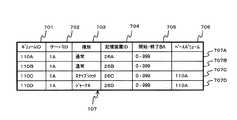
図2は、ボリューム管理テーブル107の構成を示す図である。ボリューム管理テーブル107は、各ボリュームの属性、各ボリューム間の関係及び記憶装置との対応を格納する。第1の実施の形態では、1ボリュームにつき1レコードのデータがボリューム管理テーブル107に作成される。 FIG. 2 is a diagram showing the configuration of the volume management table 107. The volume management table 107 stores the attribute of each volume, the relationship between each volume, and the correspondence with the storage device. In the first embodiment, one record of data per volume is created in the volume management table 107.
ボリューム管理テーブル107は、ボリュームIDフィールド701、サーバIDフィールド702、種別フィールド703、記憶装置IDフィールド704、開始・終了BAフィールド705及びベースボリュームフィールド706を含む。 The volume management table 107 includes a
ボリュームIDフィールド701は、各ボリュームの一意の識別子を格納する。 The
サーバIDフィールド702は、当該ボリュームにアクセスするデータベースサーバの一意の識別子を格納する。 The
種別フィールド703は、ボリュームの用途を示す種別を格納する。具体的には、DBボリューム110A及びDBログボリューム110Bは、DBMS101Aから直接アクセスされるので「通常」と設定される。スナップショットボリューム110Cは、DBボリューム110Aの複製なので「スナップショット」と設定される。ジャーナルボリューム110Dは、ジャーナルのデータを格納するので「ジャーナル」と設定される。 The
記憶装置IDフィールド704は、当該ボリュームが配置される記憶装置26の一意の識別子を格納する。開始・終了BAフィールド705は、記憶装置26において、当該ボリュームが開始するブロックアドレス及び終了するブロックアドレスを格納する。記憶装置IDフィールド704及び開始・終了BAフィールド705に格納された情報によって、当該ボリュームが物理的に格納される場所を特定することができる。 The storage
ベースボリュームフィールド706は、ボリューム種別フィールド703に設定されたボリュームの種別が「スナップショット」又は「ジャーナル」の場合に、取得元のボリュームのボリュームIDを格納する。 The
図3は、DBログ121Aの構成を示す図である。DBログ121Aは、DBデータ120Aの更新履歴をはじめとするDBMS101Aの作業履歴を格納する。 FIG. 3 is a diagram showing the configuration of the
DBログ121Aは、ログ通番フィールド401及びログレコードフィールド402を含む。ログ通番フィールド401は、DBログ121Aにレコードが追加された順序であるログ通番を格納する。ログレコードフィールド402は、データベースに対して実行された具体的な作業内容(ログデータ)を保持する。また、ログデータは、更新処理を行なった場合、更新前のデータと更新後のデータを含む。 The
DBMS101Aは、DBログ適用プログラム103を実行し、バックアップデータなどに対してDBログ121Aを適用してデータベースを回復させる。DBMS101Aは、ログデータに含まれる更新前後のデータを用いることによって、トランザクションの整合性を確保することができる。具体的には、障害発生時にトランザクションが完了している場合にはロールフォワードして更新後のデータを反映させる。また、障害発生時にトランザクションが完了していない場合にはロールバックして更新前のデータを反映させる。 The
図4は、更新ジャーナル113Aの構成を示す図である。更新ジャーナル113Aのレコードは、DBデータ120Aの更新履歴である。更新ジャーナル113Aは、更新データとしてブロックアドレスとデータイメージを保持する点でDBログ121Aと構成が異なる。データイメージとは、ディスクに記録された内容をそのまま複製したものである。また、更新ジャーナル113Aは、更新後のデータのみを保持する点でもDBログ121Aと相違する。 FIG. 4 is a diagram showing the configuration of the
更新ジャーナル113Aは、更新番号フィールド201、LBAフィールド202及びデータフィールド203を含む。 The
更新番号フィールド201は、データの更新順序を示す更新番号を格納する。更新番号は、1から順次増加する数値である。記憶装置システム2は、更新番号をレコード挿入時に自動的に付与してもよい。 The
LBAフィールド202は、更新後のデータが格納された領域の論理ブロックアドレス(LBA)を格納する。 The
データフィールド203は、更新後のデータイメージを格納する。 The
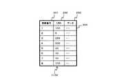
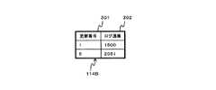
図5は、回復位置データ114Aの構成を示す図である。回復位置データ114Aは、回復ポイントを格納する。第1の実施の形態では、回復位置データ114Aは、DBログ121Aと更新ジャーナル113Aの各レコードの対応関係を格納する。 FIG. 5 is a diagram showing the configuration of the
回復位置データ114Aは、更新番号フィールド301及びログ通番フィールド302を含む。 The
更新番号フィールド301は、更新ジャーナル113Aの更新番号を格納する。 The
回復IDフィールド302は、更新番号と対応するDBログ121Aのログ通番を格納する。 The
なお、回復位置データ114Aは、前述のようにジャーナルボリューム110Dに格納されているが、DBサーバ1Aの記憶装置18Aに格納されてもよい。 The
ここで、本発明によるデータベース回復の処理について説明する。第1の実施の形態では、計算機システムの通常運用時における回復ポイントの記録処理と、障害発生時におけるデータベースの回復処理に分けることができる。 Here, the database recovery processing according to the present invention will be described. The first embodiment can be divided into recovery point recording processing during normal operation of the computer system and database recovery processing when a failure occurs.
最初に、計算機システムの通常運用時における回復ポイントの記録処理について説明する。 First, recovery point recording processing during normal operation of the computer system will be described.
図6は、チェックポイント取得プログラム102Aのフローチャートである。 FIG. 6 is a flowchart of the checkpoint acquisition program 102A.
ここで、いわゆるチェックポイントについて説明する。更新データをDBボリューム110Aに実際に記録するタイミングは、トランザクションの完了と同時ではなく、周期的に又は特定の処理に伴って行なわれる。チェックポイントとは、更新データをDBボリューム110Aに記録するタイミングをいう。また、チェックポイントを設定するということは、更新データをDBボリューム110Aに記録する処理も含む。 Here, so-called check points will be described. The timing at which the update data is actually recorded in the
DBMS101Aは、チェックポイント取得プログラム102Aを周期的に実行する。DBMS101Aは、更新データがDBボリューム110Aに記録されていない状態で一定量以上蓄積されたときに、チェックポイント取得プログラム102Aを実行してもよい。 The
まず、DBMS101Aは、チェックポイントの取得開始をDBログ121Aに追加する(ステップ501)。 First, the
次に、DBMS101Aは、チェックポイント取得処理を実行する(ステップ502)。チェックポイント取得処理は、更新データをDBボリューム110Aに記録してチェックポイントを取得する。 Next, the
チェックポイント取得処理が完了すると、DBMS101Aは、チェックポイントの取得終了をDBログ121Aに追加する(ステップ503)。 When the checkpoint acquisition process is completed, the
次に、DBMS101Aは、チェックポイント取得終了ログのログ通番及びDBボリューム110AのボリュームIDを記憶装置システム2に通知して、ジャーナル取得プログラム104を実行する(ステップ504)。 Next, the
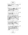
図7は、ジャーナル取得プログラム104のフローチャートである。ジャーナル取得プログラム104は、更新ジャーナル113Aに更新情報を追加し、及び回復位置データ114Aに回復ポイントを記録する。 FIG. 7 is a flowchart of the journal acquisition program 104. The journal acquisition program 104 adds update information to the
記憶装置システム2は、DBサーバ1Aからの通知を受けてジャーナル取得プログラム104を起動する。ジャーナル取得プログラム104は、制御メモリ23に格納されており、プロセッサ24によって実行される。 The
まず、記憶装置システム2は、DBサーバ1Aからの実行指示が通常の入出力指示か、回復位置通知かを判定する(ステップ801)。DBMS101は、チェックポイント取得プログラム102Aからジャーナル取得プログラム104を起動させるとき、回復位置通知フラグの値をONに設定する。記憶装置システム2は、この回復位置通知フラグの値によって実行する処理を判定する。 First, the
DBサーバ1Aからの実行指示が通常の入出力指示の場合には、記憶装置システム2は、DBサーバ1Aから通知されたボリュームIDの値からボリューム管理テーブル107を参照する。そして、指定されたボリュームが配置されている記憶装置26に対する入出力処理を実行する(ステップ802)。 When the execution instruction from the
次に、記憶装置システム2は、指示された処理が書き込みか読み出しかを判断する(ステップ803)。書き込みの場合には、ボリューム管理テーブル107を参照し、指定されたボリュームに対応するジャーナルボリュームIDを取得する(ステップ804)。 Next, the
次に、記憶装置システム2は、取得したジャーナルボリューム110Dに格納される更新ジャーナル113Aに対して、更新されたLBA及び更新後データを追加する(ステップ805)。 Next, the
一方、DBサーバ1Aからの実行指示が回復位置通知の場合には、記憶装置システム2は、通知されたボリュームIDとボリューム管理テーブル107から指定されたボリュームに対応するジャーナルボリュームIDを取得する(ステップ806)。この処理は、前述したステップ804の処理と同じである。 On the other hand, when the execution instruction from the
次に、記憶装置システム2は、取得したジャーナルボリューム110Dに格納される回復位置データ114Aに対して、更新ジャーナル113Aの最大更新番号と、サーバから通知されたDBログ121Aのログ通番を追加する(ステップ807)。 Next, the
ここで、障害発生時におけるデータベースの回復処理について説明する。データベース回復処理の概要は、まず、スナップショットボリューム110Cに更新ジャーナル114を適用する。次に、スナップショットボリューム110CをDBボリュームに切り替える。最後に、切替後のDBボリュームに対してDBログ121Aを適用してトランザクションの整合性を確保する。 Here, database recovery processing when a failure occurs will be described. As an overview of the database recovery process, first, the update journal 114 is applied to the
図8は、データベースの回復処理を行なうDB回復制御プログラム102のフローチャートである。DB回復制御プログラム102は、DBサーバ1Aが稼働している間はDBMS101Aとともに主記憶12Aに常駐する。 FIG. 8 is a flowchart of the DB recovery control program 102 that performs database recovery processing. The DB recovery control program 102 resides in the
DBサーバ1Aは、DB回復制御プログラム102を起動すると、DBボリューム110Aの破壊通知を受信するまでステップ601で待機する。破壊通知は、DBMS101AがDBボリューム110Aの障害発生を検出したときに、DBボリューム110AのボリュームIDとともに通知される。DBボリューム110Aの障害発生は、DBMS101AがDBボリューム110Aへのアクセスに失敗した原因などから判断される。 When the DB recovery control program 102 is activated, the
DBサーバ1Aは、DBボリューム110Aの破壊通知を受信すると(ステップ601)、DBログ120を参照してチェックポイント取得完了を示す最新のレコードを取得する(ステップ602)。さらに、DBサーバ1Aは、取得したレコードからログ通番401の値を取得する(ステップ603)。 When the
次に、DBサーバ1Aは、ステップ601で通知されたボリュームIDとステップ603で取得したログ通番401とを、記憶装置システム2に通知して、ジャーナル適用プログラム105の実行を指示する(ステップ604)。記憶装置システム2は、ジャーナル適用プログラム105を実行し、スナップショットボリューム110Cに更新ジャーナル113Aを適用する。その後、記憶装置システム2は、スナップショットボリューム110CをDBボリュームに切り替える。ジャーナル適用プログラム105の処理の詳細は図9にて後述する。 Next, the
次に、DBサーバ1Aは、ステップ603で取得したチェックポイント取得完了を示すレコードに対応するチェックポイント取得開始を示すレコードのログ通番401をDBログ121Aから取得する(ステップ605)。 Next, the
最後に、DBサーバ1Aは、DBMS101Aのログ適用プログラム103Aを実行する(ステップ606)。ログ適用プログラム103Aは、ステップ605で取得したログ通番以降のログを切替後のDBボリュームに対して適用する。 Finally, the
図9は、ジャーナル適用プログラム105のフローチャートである。ジャーナル適用プログラム105は、DB回復制御プログラム102からの起動指示を受けて実行される。また、記憶装置システム2は、ジャーナル適用プログラム105の起動指示とともに、破損したDBボリューム110AのボリュームIDと最新のチェックポイントを設定したときのログ通番が通知される。 FIG. 9 is a flowchart of the journal application program 105. The journal application program 105 is executed in response to an activation instruction from the DB recovery control program 102. In addition, the
記憶装置システム2は、DBサーバ1Aから通知されたボリュームIDに基づいてボリューム管理テーブル107を参照し、対応するジャーナルボリューム110Dを取得する(ステップ901)。 The
次に、記憶装置システム2は、ステップ901で取得したジャーナルボリューム110Dの回復位置データ114Aを参照する。そして、DBサーバ1Aから通知されたログ通番に対応する更新番号301の値を取得する(ステップ902)。 Next, the
次に、記憶装置システム2は、DBサーバ1Aから通知されたボリュームIDに基づいてボリューム管理テーブル107を参照し、対応するスナップショットボリューム110Cを取得する(ステップ903)。 Next, the
次に、記憶装置システム2は、ステップ903で取得したスナップショットボリューム110Cに対して更新ジャーナル113Aを適用する(ステップ904)。具体的には、LBAフィールドから求めたアドレスに対し、更新ジャーナル113Aのデータフィールドの内容を、ステップ902で取得した更新番号まで更新番号順に上書きする。 Next, the
最後に、記憶装置システム2は、スナップショットボリューム110CをDBボリュームに切り替える(ステップ905)。具体的には、ボリューム管理テーブル107に格納されたスナップショットボリューム110Cに対応するレコードについて、種別を「スナップショット」から「通常」に変更する。次に、ボリューム管理テーブル107から破損したDBボリューム110Aに該当するレコードを削除する。さらに、スナップショットボリューム110CのボリュームIDを破損したDBボリューム110AのボリュームIDに書き換える。 Finally, the
ここで、図2から図5に示した表に記載されたデータを例として、第1の実施の形態によるデータベースの回復方法の機能について説明する。 Here, the function of the database recovery method according to the first embodiment will be described using the data described in the tables shown in FIGS. 2 to 5 as an example.
まず、DBMS101AがDBデータ120Aに対して通常の入出力を行う場合の処理について説明する。 First, processing when the
DBMS101Aは、主記憶12Aに格納された更新データをDBボリューム110Aに書き込むために、図6に示すチェックポイント取得プログラム102Aを実行する。 The
DBMS101Aは、まず、チェックポイント開始を示すログレコード403BをDBログ121Aに記録する(ステップ501)。この時点でDBログ121Aに1000件のレコードが格納されているものとすると、図3に示すように、追加されたレコード403Bのログ通番は「1001」となる。 The
次に、DBMS101Aは、チェックポイント取得処理を実行する(ステップ502)。チェックポイント取得処理は、主記憶12Aに記憶された更新データをDBボリューム110Aに書き込んでチェックポイントを設定する。このとき、DBMS101Aは、データインターフェイス19を経由して記憶装置システム2に書き込み(WRITE)命令を送信する。記憶装置システム2は、この書き込み命令を受信してジャーナル取得プログラム104を実行する。 Next, the
ここから図7を参照しながら、ジャーナル取得プログラム104の処理を説明する。 The processing of the journal acquisition program 104 will now be described with reference to FIG.
記憶装置システム2がDBMS101Aから受信したWRITE命令は、通常の入出力である(ステップ801の結果が「Y」)。また、記憶装置システム2は、WRITE命令とともに、ボリュームID、LBA及び更新データを受信する。ここで、ボリュームIDは、DBボリューム110AのボリュームIDである「110A」、LBAは「100」とする。 The WRITE command received from the
記憶装置システム2は、受信したボリュームIDから書き込み対象の記憶装置を取得する。記憶装置システム2は、受信したボリュームIDと一致するボリュームIDのレコードをボリューム管理テーブル107から検索する。記憶装置システム2は、ボリュームID「110A」を受信しているため、ボリュームIDが一致するレコード707Aを取得する。この結果、記憶装置システム2は、取得したレコード707Aの記憶装置IDの値から、入出力の対象が記憶装置26Aであることを認識することができる。 The
さらに、記憶装置システム2は、受信したLBAに開始ブロックアドレスを加算することによって、更新データを書き込むブロックアドレスを特定する。開始ブロックアドレスは、レコード707Aの開始・終了BAフィールド705に格納されている。したがって、記憶装置システム2は、レコード707Aに格納された開始ブロックアドレス「0」に受信したLBA「100」を加算してブロックアドレス「100」に受信した更新データを書き込む(ステップ802)。 Furthermore, the
その後、入出力命令がWRITE命令であるため(ステップ803の結果が「Y」)、記憶装置システム2は、更新ジャーナル113Aに更新情報を記録する。 Thereafter, since the input / output command is a WRITE command (the result of
記憶装置システム2は、まず、受信したボリュームIDに対応するジャーナルボリュームを取得する(ステップ804)。具体的には、記憶装置システム2は、受信したボリュームIDとベースボリュームが一致し、かつ、種別が「ジャーナル」であるレコードをボリューム管理テーブル107から検索する。この結果、記憶装置システム2は、これらの条件に合致するレコード707Dを取得する。 The
記憶装置システム2は、ジャーナルボリューム110Dに格納されている更新ジャーナル113Aに更新情報を記録する(ステップ805)。なお、図4に示す更新ジャーナル113Aは既にレコードが追加された状態であるが、この時点ではレコードは格納されていないものとする。 The
具体的には、記憶装置システム2は、更新ジャーナル113Aにレコード204を追加する。レコード204は、更新ジャーナル113Aの最初のレコードとなるため、更新番号には「1」が設定される。また、レコード204のLBAフィールド及びデータフィールドは、DBMS101Aから入出力命令とともに送信されたLBA「100」及び更新データを格納する。 Specifically, the
DBMS101A及び記憶装置システム2は、DBボリューム110Aへの書き込みが完了していない他の更新データについても同様に処理する。このようにして、更新ジャーナル113Aには、図4に示すように更新番号1から8のレコードが追加される。 The
DBボリューム110Aへの更新データの書き込みが完了すると、再びチェックポイント取得プログラム102Aに処理が復帰する。 When the writing of the update data to the
その後、DBMS101Aは、チェックポイント終了を示すログレコード403CをDBログ121Aに記録する(ステップ503)。なお、チェックポイント取得プログラム102Aの実行中にもDBMS101Aは並行して他の処理を行なっているため、ログデータは継続して蓄積される。そのため、チェックポイントの取得開始から取得終了までの間にログ通番1002から1050までのレコードが追加され、図3に示すようにレコード403Cのログ通番は「1051」となっている。 Thereafter, the
その後、DBMS101Aは、障害発生時に回復処理の開始地点となる回復位置を記録する。具体的には、DBMS101Aは、記憶装置システム2に入出力命令として回復位置通知を送信する。DBMS101Aは、この入出力命令とともにチェックポイントの取得終了を示すレコード403Cのログ通番「1051」を記憶装置システム2に通知する(ステップ504)。このとき、DBMS101Aは、回復位置通知フラグをONに設定する。 Thereafter, the
記憶装置システム2は、回復位置通知を受信すると、ジャーナル取得プログラム104を実行する。ここで、再び図7を参照しながら、ジャーナル取得プログラム104の回復位置通知処理を説明する。 When the
記憶装置システム2が受信した回復位置通知には、チェックポイント終了ログのログ通番「1051」の他に、回復対象となるDBボリューム110AのボリュームID「110A」を含む。 The recovery position notification received by the
記憶装置システム2は、回復位置通知フラグを参照し、受信した入出力命令が通常の入出力でないと判定する(ステップ801の結果が「N」)。 The
次に、記憶装置システム2は、受信したボリュームID「110A」とベースボリュームの値が一致し、かつ、種別が「ジャーナル」であるレコードをボリューム管理テーブル107から検索する(ステップ806)。この結果、記憶装置システム2は、これらの条件に満たすレコード707Dを取得する。 Next, the
記憶装置システム2は、ジャーナルボリューム110Dに格納されている回復位置データ114Aにレコード303を追加する(ステップ807)。回復位置データ114Aは、更新ジャーナル113Aの最新の更新番号302とDBログ121Aのチェックポイント終了ログのログ通番401との対応関係を格納する。したがって、更新番号フィールド301には更新ジャーナル113Aを参照して「8」が、ログ通番フィールド302には通知されたログ通番「1051」がレコード303として格納される。 The
回復位置データ114Aに対するデータの追加が完了すると、ジャーナル取得プログラム104の処理は完了する。その後、記憶装置システム2は、DBMS101Aに処理を復帰させる。また、チェックポイント取得プログラム102Aの処理も、回復位置データ114Aへのデータの追加をもって完了する。 When the addition of data to the
以上のように、DBMS101Aは、チェックポイント取得プログラム102Aを実行し、更新データの書き込みと同時に、回復ポイントを記憶装置システム2の回復位置データ114Aに記録する。 As described above, the
次に、記憶装置26Aに障害が発生したときに、DBデータ120Aを回復させるための処理について説明する。 Next, processing for recovering the DB data 120A when a failure occurs in the
DB回復制御プログラム102は、DBサーバ1Aの起動とともに実行され、正常に稼働している間は主記憶12Aに常駐する。そして、DBサーバ1Aは、DBボリューム110Aの破壊通知を受信するまでDB回復制御プログラム102の処理を待機させる(ステップ601)。 The DB recovery control program 102 is executed when the
破壊通知は、DBMS101AがDBボリューム110Aの障害発生を検出したときに通知される。DBボリューム110Aの障害発生は、DBMS101AがDBボリューム110Aへのアクセスに失敗した原因などから判断される。 The destruction notification is notified when the
DBサーバ1Aは、DBボリューム110Aの破壊通知を受信すると、DBログ120からチェックポイント取得完了を示す最新のレコードを取得する(ステップ602)。図3を参照すると、レコード403Cが最新のレコードに該当する。DBサーバ1Aは、レコード403Cからログ通番「1051」を取得する(ステップ603)。 When the
その後、DBサーバ1Aは、記憶装置システム2にジャーナル適用プログラム105の実行を指示する(ステップ604)。このとき、DBサーバ1Aは、記憶装置システム2にDBボリューム110AのボリュームID「110A」とログ通番「1051」を通知する(ステップ604)。 Thereafter, the
記憶装置システム2は、DBサーバ1Aから通知を受けると、ジャーナル適用プログラム105を実行する。 When the
記憶装置システム2は、まず、受信したボリュームIDに対応するジャーナルボリュームを取得する(ステップ901)。具体的には、記憶装置システム2は、受信したボリュームIDとベースボリュームが一致し、かつ、種別が「ジャーナル」であるレコードをボリューム管理テーブル107から検索する。この結果、記憶装置システム2は、これらの条件に合致するレコード707Dを取得する。本例では、ジャーナルボリューム110Dが取得される。 The
次に、記憶装置システム2は、ジャーナルボリューム110Dに格納された回復位置データ114Aを参照する。記憶装置システム2は、DBサーバ1Aから通知されたログ通番を元に回復位置データ114Aを検索し、対応する更新番号を得る(ステップ902)。図5によると、通知されたログ通番は「1051」であるため、レコード303が検索され、更新番号「8」を得る。 Next, the
次に、記憶装置システム2は、受信したボリュームIDに対応するスナップショットボリュームを取得する(ステップ903)。具体的には、記憶装置システム2は、受信したボリュームIDとベースボリュームが一致し、かつ、種別が「スナップショット」であるレコードをボリューム管理テーブル107から検索する。この結果、記憶装置システム2は、これらの条件に合致するレコード707Cを取得する。本例では、スナップショットボリューム110Cが取得される。 Next, the
次に、記憶装置システム2は、更新ジャーナル113Aに格納された更新情報をスナップショットボリューム110Cに適用する(ステップ904)。記憶装置システム2は、ステップ902で取得した更新番号までの更新情報を更新番号順に適用する。 Next, the
具体的には、記憶装置システム2は、例えば、更新ジャーナル113Aのレコード204を適用する場合、スナップショットボリューム110Cの開始ブロックアドレス「0」に論理ブロックアドレス「100」を加算して絶対アドレス「100」を算出することができる。そして、記憶装置システム2は、このアドレスにデータフィールド203の内容を上書きする。 Specifically, for example, when the
このようにして、最新のチェックポイントまでの更新情報がスナップショットボリューム110Cに反映される。このとき、記憶装置システム2は、更新を反映させた更新ジャーナル113Aの更新情報を削除する。こうすることによって、更新ジャーナル113Aの適用開始位置を保持する必要がなくなる。 In this way, update information up to the latest checkpoint is reflected in the
以上より、DBデータ120Aは、スナップショットボリューム110Cに更新番号8までの更新情報が反映された状態まで復元される。 As described above, the DB data 120A is restored to a state in which the update information up to the
その後、記憶装置システム2は、スナップショットボリューム110CをDBボリュームに変更する(ステップ905)。具体的には、記憶装置システム2は、まず、ボリューム管理テーブル107に格納された破損したDBボリューム110Aに対応するレコード707Aを削除する。そして、記憶装置システム2は、スナップショットボリューム110Cに対応するレコード707CのボリュームIDを「110C」からDBサーバ1Aより通知されたボリュームID「110A」に変更する。さらに、記憶装置システム2は、種別703を「通常」に変更して、ベースボリューム706の値を消去する。 Thereafter, the
DBボリュームの切替が完了すると、ジャーナル適用プログラム105の処理が終了し、記憶装置システム2は、DBサーバ1Aに処理を復帰させる。 When the switching of the DB volume is completed, the processing of the journal application program 105 ends, and the
DBボリュームの切替後のDBデータ120Aは、この時点では、最新のチェックポイントまでの更新が反映されている。したがって、チェックポイント以降の更新情報が反映されておらず、トランザクションの整合性は確保されていない。そこで、DBサーバ1Aは、切替後のDBデータ120Aに対してDBログ121Aを適用し、トランザクションの整合性を確保する。 The DB data 120A after switching the DB volume reflects the update up to the latest checkpoint at this point. Therefore, update information after the checkpoint is not reflected, and transaction consistency is not ensured. Therefore, the
DBサーバ1Aは、まず、ステップ603で取得したチェックポイント取得完了レコード403Cに対応するチェックポイント取得開始レコードをDBログ121Aから取得する(ステップ605)。本例では、ログ通番「1001」のレコード403Bがチェックポイント取得開始レコードに該当する。 First, the
次に、DBサーバ1Aは、ログ適用プログラム103Aを実行し、ログ通番「1001」以降のログレコードを切替後のDBデータ120Aに対して適用する。そこで、障害発生までにコミットが完了しているデータについてはロールフォワードを行い、コミットが完了していないデータについてはロールバックを行なってトランザクションの整合性を確保する。 Next, the
以上の処理をもって、ログ適用プログラム103Aの実行が完了し、データベースの回復処理が終了する。 With the above processing, the execution of the log application program 103A is completed, and the database recovery processing ends.
第1の実施の形態によれば、DBサーバ1Aは、更新ジャーナル113Aによるデータベースの回復とDBログ121Aによる回復とを併用する。また、トランザクションの整合性を確保しながら、ジャーナル適用プログラム105による回復範囲ができるだけ広範囲となるように、チェックポイントと連動させて回復ポイントを設定する。 According to the first embodiment, the
ジャーナル適用プログラム105による処理は、記憶装置システム2内で完結するため、DBサーバ1Aと記憶装置システム2との間の転送データ量を削減することができる。さらに、記憶装置の絶対アドレスに対して直接更新データを書き込むため、高速にデータを復元することができる。 Since the processing by the journal application program 105 is completed within the
また、最新のチェックポイント以降の更新データについては、更新ジャーナル113Aの適用後のデータに対してDBログ121Aを適用することによって、トランザクションの整合性を確実に保証することができる。 For update data after the latest checkpoint, the consistency of transactions can be reliably ensured by applying the DB log 121A to the data after the application of the
したがって、第1の実施の形態によれば、トランザクションの整合性を確保しながら、高速にデータベースを回復させることができる。 Therefore, according to the first embodiment, the database can be recovered at a high speed while ensuring the consistency of transactions.
また、第1の実施の形態によれば、チェックポイント以降のDBログ121Aを保持すればよい。したがって、チェックポイント以前のDBログ121Aを退避して管理対象の更新ログを減らすことができ、管理負担を軽減することができる。 Further, according to the first embodiment, the
(第2の実施の形態)
第2の実施の形態では、データベースサーバが複数存在する計算機システムに対して本発明のデータベースの回復方法を適用した実施の形態について説明する。なお、第1の実施の形態と同様の機能を果たす構成には同一の符号を付して重複する説明を適宜省略する。(Second Embodiment)
In the second embodiment, an embodiment in which the database recovery method of the present invention is applied to a computer system having a plurality of database servers will be described. In addition, the same code | symbol is attached | subjected to the structure which performs the function similar to 1st Embodiment, and the overlapping description is abbreviate | omitted suitably.
図10は、2つのDBサーバ1A及び1Bを含む計算機システムの構成を示す。第2の実施の形態の計算機システムは、2つのDBサーバ1A及び1Bが記憶装置システム2に対してアクセスする。DBサーバ1Aの構成は、第1の実施の形態のDBサーバ1Aと同じである。DBサーバ1Bの構成も、第1の実施の形態のDBサーバ1Aと略同じである。 FIG. 10 shows a configuration of a computer system including two
DBサーバ1Aは、第1の実施の形態と同様にデータインターフェイス19Aを経由して第1のネットワーク3Aに接続する。同様に、DBサーバ1Bは、データインターフェイス19Bを経由して第3のネットワーク3Bに接続する。さらに、DBサーバ1Aは、ネットワークインタフェース13Aを経由して第2のネットワーク4に接続する。また、DBサーバ1Bは、ネットワークインタフェース13Bを経由して第2のネットワーク4に接続する。 The
記憶装置システム2の構成は、第1の実施の形態の記憶装置システム2と略同様である。記憶装置システム2は、ポート21A及び21Bを備える。記憶装置システム2は、ポート21Aを経由して第1のネットワーク3AからDBサーバ1Aと接続する。同様に、記憶装置システム2は、ポート21Bを経由して第3のネットワーク3BからDBサーバ1Bと接続する。 The configuration of the
記憶装置26A〜26Dは、DBサーバ1Aによってアクセスされるボリューム110A〜110Dに加えて、DBサーバ1Bによってアクセスされるボリューム110E〜110Hを備える。ボリューム110E〜110Hは、それぞれ同一の記憶装置に格納されているボリューム110A〜110Dとそれぞれ同じ用途である。例えば、DBボリューム110Eは、DBボリューム110Aを備える記憶装置26Aに配置される。さらに、他のボリューム110F〜110Hについても同じである。 The
また、DBボリューム110Eは、DBMS101BによってアクセスされるDBデータ120Bを格納する。同様に、DBログボリューム110Fは、DBログ121Bを格納する。さらに、ジャーナルボリューム110Hは、DBボリューム110Eの更新ジャーナル113B及び回復位置データ114Bを格納する。 The
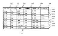
ボリューム管理テーブル107は、第1の実施の形態と同様に各ボリュームの情報を格納して管理する。ボリューム110E〜110Hは、具体的には、図11に示すようにレコード707E〜707Hのように表わされる。また、レコード707A〜707Dは、第1の実施の形態と同じボリューム110A〜110Dを表わしている。 The volume management table 107 stores and manages information on each volume, as in the first embodiment. Specifically, the
図12は、DBボリューム110EのDBログ121Bの例を示す。また、図13は、DBボリューム110Eの更新ジャーナル113Bの例である。さらに、図14は、DBボリューム110Eの回復位置データ114Bの例である。これらのテーブルの構成は、すべて第1の実施の形態と同様である。これらのテーブルには、DBMS101Bによるアクセスに基づくデータが記録されている。 FIG. 12 shows an example of the DB log 121B of the
以下、記憶装置26Aに障害が発生したときに、DBデータ120A及び120Bを回復する方法について説明する。 Hereinafter, a method for recovering the DB data 120A and 120B when a failure occurs in the
第2の実施の形態の計算機システムは、図10に示す構成を備える。ボリューム管理テーブル107は、図11に示すデータを格納する。その他のデータの構成及び内容は、DBサーバ1Aについては図3〜5に示したデータ、DBサーバ1Bについては図12〜14に示したデータと同じである。また、各DBサーバに格納されているプログラムについても、第1の実施の形態と同じである。 The computer system according to the second embodiment has the configuration shown in FIG. The volume management table 107 stores the data shown in FIG. The configuration and contents of other data are the same as the data shown in FIGS. 3 to 5 for the
DBMS101Aは、記憶装置26Aの破壊を検知すると、DB回復制御プログラム106Aを実行してデータベースを回復させる。同様に、DBMS101Bは、DB回復制御プログラム106Bを実行する。 When the
DB回復制御プログラム106A及び106Bは、それぞれ独立して図8に示した処理を実行する。したがって、DB回復制御プログラム106A及び106Bは、それぞれ記憶装置システム2に通知してジャーナル適用プログラム105を実行させる。そこで、記憶装置システム2は、それぞれ独立に図9に示した処理を実行する。処理の具体的な内容の説明については、第1の実施の形態と同様であるため省略する。 The DB recovery control programs 106A and 106B independently execute the process shown in FIG. Accordingly, the DB recovery control programs 106A and 106B notify the
その後、DBボリューム110Aがスナップショットボリューム110Cに切り替えられ、DBボリューム110Eがスナップショットボリューム110Gに切り替えられる。さらに、ログ適用プログラム103A及び103Bが適用されるため、ボリューム切替後の各DBデータ120A及び120Bは、トランザクションの整合性が確保された状態で回復される。 Thereafter, the
以上示したように、データベースサーバを複数備える計算機システムであっても、本発明によるデータベース回復方法を適用することができる。 As described above, the database recovery method according to the present invention can be applied even to a computer system including a plurality of database servers.
したがって、複数のデータベースサーバが連携して稼働する大規模な計算機システムについても、記憶装置に障害が発生したときに、データベースをトランザクションの整合性を確保した状態まで短時間で回復させることができる。 Accordingly, even for a large-scale computer system in which a plurality of database servers operate in cooperation, when a failure occurs in a storage device, the database can be recovered to a state in which transaction consistency is ensured in a short time.
1A、1B DBサーバ
11A、11B CPU
12A、12B 主記憶
13A、13B ネットワークインタフェース
14A、14B ディスプレイ
15A、15B キーボード
16A、16B CD−ROM
17A、17B コントローラ
18A、18B 記憶装置
19A、19B データインタフェース
2 記憶装置システム
21A、21B ポート
22 ディスクコントローラ
23 制御メモリ
24 プロセッサ
25 キャッシュメモリ
26A〜26D 記憶装置
27 ネットワークインタフェース
3A 第1のネットワーク
3B 第3のネットワーク
4 第2のネットワーク
101A、101B データベース管理システム
102A、102B チェックポイント取得プログラム
103A、103B ログ適用プログラム
104 ジャーナル取得プログラム
105 ジャーナル適用プログラム
106A、106A DB回復制御プログラム
107 ボリューム管理テーブル
110A、110E DBボリューム
110B、110F DBログボリューム
110C、110G スナップショットボリューム
110D、110H ジャーナルボリューム
113A、113B 更新ジャーナル
114A、114B 回復位置データ
120A、120B DBデータ
121A、121B DBログ1A,
12A,
17A, 17B Controller 18A,
Claims (12)
Translated fromJapanese前記計算機は、前記記憶装置システムに接続されるポート、前記ポートに接続されるプロセッサ、及び前記プロセッサに接続されるメモリを備え、
前記記憶装置システムは、前記計算機に接続されるポート、前記ポートに接続されプロセッサ及びメモリを備える制御部、及び前記計算機から書き込み要求がされるデータを格納するディスクドライブを備え、
前記ディスクドライブは、前記データを格納するデータボリューム、前記データボリュームの複製であるスナップショットボリューム、前記データの更新ログを格納するデータベースログ、及び前記データボリュームの更新情報を保持する更新ジャーナルを保持し、
前記データベース管理システムは、前記データボリュームが破損したときに前記更新ジャーナルを適用する範囲と前記データベースログを適用する範囲とを切り替える回復ポイントを記録するものとし、
前記データベース回復方法は、
前記スナップショットボリュームに前記更新ジャーナルのうち前記回復ポイントにより特定される範囲の更新ジャーナルを適用するステップと、
更新後の前記スナップショットボリュームを前記破損したデータボリュームに代わるデータボリュームとして切り替えるステップと、
前記切り替えられたデータボリュームに対して前記データベースログのうち前記回復ポイントにより特定される範囲のデータベースログを適用するステップとを有することを特徴とするデータベース回復方法。A database recovery method in a computer system, comprising: a computer having a database management system; and a storage system that stores data accessed from the computer,
The computer includes a port connected to the storage system, a processor connected to the port, and a memory connected to the processor,
The storage device system includes a port connected to the computer, a control unit connected to the port and including a processor and a memory, and a disk drive for storing data requested to be written from the computer,
The disk drive holds a data volume that stores the data, a snapshot volume that is a duplicate of the data volume, a database log that stores the update log of the data, and an update journal that holds update information of the data volume. ,
The database management system records a recovery point for switching between a range to which the update journal is applied and a range to which the database log is applied when the data volume is damaged,
The database recovery method includes:
Applying anupdate journal in a range specified by the recovery pointamong the update journals to the snapshot volume;
And Step toggleits said snapshot volume after updatingas data volume in place of the corrupted datavolume,
Database recoverymethod characterized bya step of applying a database logrange specified by the recovery pointamong the database log to the switched data volume.
前記回復ポイントは、最新のチェックポイントを設定したときに記録されることを特徴とする請求項1に記載のデータベース回復方法。The database management system temporarily stores the updated data, sets a checkpoint for recording the updated data stored at a predetermined timing in a batch on the data volume,
The database recovery method according to claim 1, wherein the recovery point is recorded when a latest checkpoint is set.
前記回復ポイントは、前記データベースログに記録されたチェックポイントと、前記更新ジャーナルの最新の更新情報との対応関係を含むことを特徴とする請求項5に記載のデータベース回復方法。The checkpoint is recorded in the database log,
6. The database recovery method according to claim 5, wherein the recovery point includes a correspondence relationship between a check point recorded in the database log and the latest update information of the update journal.
前記計算機は、前記記憶装置システムに接続されるポート、前記ポートに接続されるプロセッサ、及び前記プロセッサに接続されるメモリを備え、
前記記憶装置システムは、前記計算機に接続されるポート、前記ポートに接続されプロセッサ及びメモリを備える制御部、及び前記計算機から書き込み要求がされるデータを格納するディスクドライブを備え、
前記ディスクドライブは、前記データを格納するデータボリューム、前記データボリュームの複製であるスナップショットボリューム、前記データの更新ログを格納するデータベースログ、及び前記データボリュームの更新情報を保持する更新ジャーナルを保持し、
前記データベース管理システムは、前記計算機システムが正常に稼働している間に、前記データボリュームが破損したときに前記更新ジャーナルを適用する範囲と前記データベースログを適用する範囲とを切り替える回復ポイントを記録し、前記データボリュームに障害が発生したときには、前記スナップショットボリュームに前記更新ジャーナルを前記回復ポイントまで適用し、前記スナップショットボリュームを前記データボリュームに切り替え、さらに、前記回復ポイント以降の前記データベースログを適用する、
ことを特徴とする計算機システム。A computer system comprising: a computer having a database management system; and a storage device system for storing data accessed from the computer,
The computer includes a port connected to the storage system, a processor connected to the port, and a memory connected to the processor,
The storage device system includes a port connected to the computer, a control unit connected to the port and including a processor and a memory, and a disk drive for storing data requested to be written from the computer,
The disk drive holds a data volume that stores the data, a snapshot volume that is a duplicate of the data volume, a database log that stores the update log of the data, and an update journal that holds update information of the data volume. ,
The database management system records a recovery point for switching between a range to which the update journal is applied and a range to which the database log is applied when the data volume is damaged while the computer system is operating normally. When a failure occurs in the data volume, the update journal is applied to the snapshot volume up to the recovery point, the snapshot volume is switched to the data volume, and the database log after the recovery point is applied. To
A computer system characterized by that.
前記回復ポイントは、最新のチェックポイントを設定したときに記録されることを特徴とする請求項7に記載の計算機システム。The database management system has a checkpoint setting function for temporarily storing updated data, and collectively recording the updated data stored at a predetermined timing in the data volume,
The computer system according to claim 7, wherein the recovery point is recorded when a latest checkpoint is set.
前記回復ポイントは、前記データベースログに記録されたチェックポイントと、前記更新ジャーナルの最新の更新情報との対応関係を含むことを特徴とする請求項11に記載の計算機システム。The checkpoint is recorded in the database log,
12. The computer system according to claim 11, wherein the recovery point includes a correspondence relationship between a check point recorded in the database log and the latest update information of the update journal.
Priority Applications (3)
| Application Number | Priority Date | Filing Date | Title |
|---|---|---|---|
| JP2006019245AJP4839091B2 (en) | 2006-01-27 | 2006-01-27 | Database recovery method and computer system |
| US11/386,982US7472139B2 (en) | 2006-01-27 | 2006-03-23 | Database recovery method applying update journal and database log |
| US12/329,143US7991749B2 (en) | 2006-01-27 | 2008-12-05 | Database recovery method applying update journal and database log |
Applications Claiming Priority (1)
| Application Number | Priority Date | Filing Date | Title |
|---|---|---|---|
| JP2006019245AJP4839091B2 (en) | 2006-01-27 | 2006-01-27 | Database recovery method and computer system |
Publications (3)
| Publication Number | Publication Date |
|---|---|
| JP2007200114A JP2007200114A (en) | 2007-08-09 |
| JP2007200114A5 JP2007200114A5 (en) | 2008-12-11 |
| JP4839091B2true JP4839091B2 (en) | 2011-12-14 |
Family
ID=38335268
Family Applications (1)
| Application Number | Title | Priority Date | Filing Date |
|---|---|---|---|
| JP2006019245AActiveJP4839091B2 (en) | 2006-01-27 | 2006-01-27 | Database recovery method and computer system |
Country Status (2)
| Country | Link |
|---|---|
| US (2) | US7472139B2 (en) |
| JP (1) | JP4839091B2 (en) |
Cited By (1)
| Publication number | Priority date | Publication date | Assignee | Title |
|---|---|---|---|---|
| US10599530B2 (en) | 2015-11-04 | 2020-03-24 | Hitachi, Ltd. | Method and apparatus for recovering in-memory data processing system |
Families Citing this family (42)
| Publication number | Priority date | Publication date | Assignee | Title |
|---|---|---|---|---|
| JP4704893B2 (en)* | 2005-11-15 | 2011-06-22 | 株式会社日立製作所 | Computer system, management computer, storage system, and backup management method |
| US8069439B2 (en)* | 2006-03-30 | 2011-11-29 | Microsoft Corporation | Framework for modeling continuations in workflows |
| JP4859605B2 (en)* | 2006-09-20 | 2012-01-25 | 株式会社日立製作所 | Information processing system |
| US20080256312A1 (en)* | 2007-04-12 | 2008-10-16 | International Business Machines Corporation | Apparatus and method to detect and repair a broken dataset |
| US7979742B2 (en)* | 2007-07-19 | 2011-07-12 | Hewlett-Packard Development Company, L.P. | Recoverability of a dataset associated with a multi-tier storage system |
| JP4560074B2 (en)* | 2007-09-26 | 2010-10-13 | 株式会社東芝 | Virtual computer system and virtual computer restoration method in the same system |
| JP2009080692A (en)* | 2007-09-26 | 2009-04-16 | Toshiba Corp | Virtual computer system and service takeover control method in the same system |
| JP4510064B2 (en)* | 2007-09-27 | 2010-07-21 | 株式会社東芝 | Virtual computer system and virtual machine restoration method in the same system |
| US8286030B1 (en) | 2009-02-09 | 2012-10-09 | American Megatrends, Inc. | Information lifecycle management assisted asynchronous replication |
| JP5091894B2 (en)* | 2009-03-13 | 2012-12-05 | 株式会社日立製作所 | Stream recovery method, stream recovery program, and failure recovery apparatus |
| US8332365B2 (en)* | 2009-03-31 | 2012-12-11 | Amazon Technologies, Inc. | Cloning and recovery of data volumes |
| US8713060B2 (en) | 2009-03-31 | 2014-04-29 | Amazon Technologies, Inc. | Control service for relational data management |
| US9705888B2 (en) | 2009-03-31 | 2017-07-11 | Amazon Technologies, Inc. | Managing security groups for data instances |
| US9207984B2 (en) | 2009-03-31 | 2015-12-08 | Amazon Technologies, Inc. | Monitoring and automatic scaling of data volumes |
| US8307003B1 (en) | 2009-03-31 | 2012-11-06 | Amazon Technologies, Inc. | Self-service control environment |
| US9135283B2 (en) | 2009-10-07 | 2015-09-15 | Amazon Technologies, Inc. | Self-service configuration for data environment |
| JP5039891B2 (en)* | 2009-10-19 | 2012-10-03 | インターナショナル・ビジネス・マシーンズ・コーポレーション | Apparatus and method for generating a replica of a database |
| US8676753B2 (en) | 2009-10-26 | 2014-03-18 | Amazon Technologies, Inc. | Monitoring of replicated data instances |
| US8335765B2 (en) | 2009-10-26 | 2012-12-18 | Amazon Technologies, Inc. | Provisioning and managing replicated data instances |
| US8074107B2 (en) | 2009-10-26 | 2011-12-06 | Amazon Technologies, Inc. | Failover and recovery for replicated data instances |
| US8805711B2 (en)* | 2009-12-22 | 2014-08-12 | International Business Machines Corporation | Two-layer data architecture for reservation management systems |
| US8930321B2 (en) | 2010-06-30 | 2015-01-06 | Microsoft Corporation | Logical recovery with unbundled transaction services |
| IL208641A0 (en)* | 2010-10-12 | 2010-12-30 | Eci Telecom Ltd | Method for accelerating start up of a computerized system |
| JP5825655B2 (en)* | 2010-12-09 | 2015-12-02 | 日本電気株式会社 | Replication system |
| US9582382B1 (en)* | 2010-12-16 | 2017-02-28 | EMC IP Holding Company LLC | Snapshot hardening |
| JP5759203B2 (en)* | 2011-02-25 | 2015-08-05 | インターナショナル・ビジネス・マシーンズ・コーポレーションInternational Business Machines Corporation | Asynchronous checkpoint acquisition and recovery from iterative parallel computer computations |
| US11003687B2 (en) | 2012-05-15 | 2021-05-11 | Splunk, Inc. | Executing data searches using generation identifiers |
| US9130971B2 (en) | 2012-05-15 | 2015-09-08 | Splunk, Inc. | Site-based search affinity |
| US10387448B2 (en) | 2012-05-15 | 2019-08-20 | Splunk Inc. | Replication of summary data in a clustered computing environment |
| US8788459B2 (en) | 2012-05-15 | 2014-07-22 | Splunk Inc. | Clustering for high availability and disaster recovery |
| US9003162B2 (en) | 2012-06-20 | 2015-04-07 | Microsoft Technology Licensing, Llc | Structuring storage based on latch-free B-trees |
| EP2975523A4 (en) | 2013-03-12 | 2017-02-08 | Toshiba Solutions Corporation | Database system, program, and data processing method |
| US9665599B2 (en) | 2013-06-03 | 2017-05-30 | International Business Machines Corporation | Maintaining database consistency when nearing the end of a database recovery log |
| US9519591B2 (en) | 2013-06-22 | 2016-12-13 | Microsoft Technology Licensing, Llc | Latch-free, log-structured storage for multiple access methods |
| WO2015025384A1 (en) | 2013-08-21 | 2015-02-26 | 株式会社東芝 | Database system, program, and data processing method |
| JP6122126B2 (en) | 2013-08-27 | 2017-04-26 | 株式会社東芝 | Database system, program, and data processing method |
| WO2015183316A1 (en)* | 2014-05-30 | 2015-12-03 | Hewlett-Packard Development Company, L. P. | Partially sorted log archive |
| US9514211B2 (en) | 2014-07-20 | 2016-12-06 | Microsoft Technology Licensing, Llc | High throughput data modifications using blind update operations |
| US10339101B1 (en)* | 2015-09-11 | 2019-07-02 | Cohesity, Inc. | Distributed write journals that support fast snapshotting for a distributed file system |
| CN107544859B (en)* | 2017-07-12 | 2020-11-24 | 上海交通大学 | Checkpointing methods used to ensure data consistency on mixed memory systems |
| CN109117086B (en)* | 2018-07-16 | 2021-09-21 | 北京百度网讯科技有限公司 | Storage device data position processing method, device, equipment and storage medium |
| US11372976B2 (en)* | 2020-07-08 | 2022-06-28 | Hitachi, Ltd. | Accelerating method of snapshot investigation for rollback from ransomware |
Family Cites Families (13)
| Publication number | Priority date | Publication date | Assignee | Title |
|---|---|---|---|---|
| EP0516900B1 (en) | 1991-06-04 | 1996-05-01 | International Business Machines Corporation | Data backup and recovery in a data processing system |
| US6877109B2 (en)* | 2001-11-19 | 2005-04-05 | Lsi Logic Corporation | Method for the acceleration and simplification of file system logging techniques using storage device snapshots |
| US7426559B2 (en)* | 2002-05-09 | 2008-09-16 | International Business Machines Corporation | Method for sequential coordination of external database application events with asynchronous internal database events |
| US7353305B2 (en)* | 2002-06-28 | 2008-04-01 | Brocade Communications Systems, Inc. | Apparatus and method for data virtualization in a storage processing device |
| US7398422B2 (en) | 2003-06-26 | 2008-07-08 | Hitachi, Ltd. | Method and apparatus for data recovery system using storage based journaling |
| US7111136B2 (en) | 2003-06-26 | 2006-09-19 | Hitachi, Ltd. | Method and apparatus for backup and recovery system using storage based journaling |
| JP4321705B2 (en)* | 2003-07-29 | 2009-08-26 | 株式会社日立製作所 | Apparatus and storage system for controlling acquisition of snapshot |
| US7490103B2 (en)* | 2004-02-04 | 2009-02-10 | Netapp, Inc. | Method and system for backing up data |
| US7783606B2 (en)* | 2004-02-04 | 2010-08-24 | Netapp, Inc. | Method and system for remote data recovery |
| JP4483342B2 (en)* | 2004-02-27 | 2010-06-16 | 株式会社日立製作所 | System recovery method |
| JP2006004031A (en)* | 2004-06-16 | 2006-01-05 | Hitachi Ltd | Data processing method and system, storage apparatus method and processing program therefor |
| US7549027B1 (en)* | 2004-07-01 | 2009-06-16 | Emc Corporation | System and method for managing replication of data in a data storage environment |
| US7840539B2 (en)* | 2006-01-24 | 2010-11-23 | International Business Machines Corporation | Method and system for building a database from backup data images |
- 2006
- 2006-01-27JPJP2006019245Apatent/JP4839091B2/enactiveActive
- 2006-03-23USUS11/386,982patent/US7472139B2/enactiveActive
- 2008
- 2008-12-05USUS12/329,143patent/US7991749B2/enactiveActive
Cited By (1)
| Publication number | Priority date | Publication date | Assignee | Title |
|---|---|---|---|---|
| US10599530B2 (en) | 2015-11-04 | 2020-03-24 | Hitachi, Ltd. | Method and apparatus for recovering in-memory data processing system |
Also Published As
| Publication number | Publication date |
|---|---|
| US20070185923A1 (en) | 2007-08-09 |
| US7991749B2 (en) | 2011-08-02 |
| US7472139B2 (en) | 2008-12-30 |
| US20090125568A1 (en) | 2009-05-14 |
| JP2007200114A (en) | 2007-08-09 |
Similar Documents
| Publication | Publication Date | Title |
|---|---|---|
| JP4839091B2 (en) | Database recovery method and computer system | |
| JP4550541B2 (en) | Storage system | |
| JP4809040B2 (en) | Storage apparatus and snapshot restore method | |
| US8209507B2 (en) | Storage device and information management system | |
| US7860836B1 (en) | Method and apparatus to recover data in a continuous data protection environment using a journal | |
| JP3992427B2 (en) | File system | |
| JP2003223287A (en) | Storage device, backup method and program for the storage device | |
| JP4884041B2 (en) | Storage system for issuing optimal I/O commands to automatically expandable volumes and control method thereof | |
| JP2004127294A (en) | Virtual storage system and its operation method | |
| JP4398464B2 (en) | System, method, and program for managing point-in-time copy relationships between one target volume and one source volume | |
| JP4249719B2 (en) | Backup system, program, and backup method | |
| JP2006004031A (en) | Data processing method and system, storage apparatus method and processing program therefor | |
| CN108604201B (en) | Snapshot rollback method, device, storage controller and system | |
| JP2002132554A (en) | Database access method | |
| WO2007099636A1 (en) | File system migration method, program and apparatus | |
| JP2008033527A (en) | Storage device, disk device, and data restoration method | |
| US10078558B2 (en) | Database system control method and database system | |
| JP2006268139A (en) | Data reproduction device, method and program and storing system | |
| US8527723B1 (en) | Storage system and control method for storage system | |
| US8131958B2 (en) | Storage system, storage device, and data updating method using a journal volume | |
| US20210232466A1 (en) | Storage system and restore control method | |
| JP4394467B2 (en) | Storage system, server apparatus, and preceding copy data generation method | |
| US9513809B2 (en) | Obtaining additional data storage from another data storage system | |
| US10656867B2 (en) | Computer system, data management method, and data management program | |
| CN115599756A (en) | Data writing method, storage medium and device for database |
Legal Events
| Date | Code | Title | Description |
|---|---|---|---|
| A521 | Request for written amendment filed | Free format text:JAPANESE INTERMEDIATE CODE: A523 Effective date:20081024 | |
| A621 | Written request for application examination | Free format text:JAPANESE INTERMEDIATE CODE: A621 Effective date:20081024 | |
| A977 | Report on retrieval | Free format text:JAPANESE INTERMEDIATE CODE: A971007 Effective date:20110602 | |
| A131 | Notification of reasons for refusal | Free format text:JAPANESE INTERMEDIATE CODE: A131 Effective date:20110712 | |
| A521 | Request for written amendment filed | Free format text:JAPANESE INTERMEDIATE CODE: A523 Effective date:20110902 | |
| TRDD | Decision of grant or rejection written | ||
| A01 | Written decision to grant a patent or to grant a registration (utility model) | Free format text:JAPANESE INTERMEDIATE CODE: A01 Effective date:20110927 | |
| A01 | Written decision to grant a patent or to grant a registration (utility model) | Free format text:JAPANESE INTERMEDIATE CODE: A01 | |
| A61 | First payment of annual fees (during grant procedure) | Free format text:JAPANESE INTERMEDIATE CODE: A61 Effective date:20111003 | |
| FPAY | Renewal fee payment (event date is renewal date of database) | Free format text:PAYMENT UNTIL: 20141007 Year of fee payment:3 | |
| R150 | Certificate of patent or registration of utility model | Ref document number:4839091 Country of ref document:JP Free format text:JAPANESE INTERMEDIATE CODE: R150 Free format text:JAPANESE INTERMEDIATE CODE: R150 |