JP4838267B2 - Small incision intraocular lens having anti-PCO function - Google Patents
Small incision intraocular lens having anti-PCO functionDownload PDFInfo
- Publication number
- JP4838267B2 JP4838267B2JP2007549487AJP2007549487AJP4838267B2JP 4838267 B2JP4838267 B2JP 4838267B2JP 2007549487 AJP2007549487 AJP 2007549487AJP 2007549487 AJP2007549487 AJP 2007549487AJP 4838267 B2JP4838267 B2JP 4838267B2
- Authority
- JP
- Japan
- Prior art keywords
- intraocular lens
- lens according
- approximately
- iol
- optical
- Prior art date
- Legal status (The legal status is an assumption and is not a legal conclusion. Google has not performed a legal analysis and makes no representation as to the accuracy of the status listed.)
- Active
Links
- 230000003287optical effectEffects0.000claimsdescription81
- 230000002093peripheral effectEffects0.000claimsdescription31
- 230000035807sensationEffects0.000claimsdescription18
- 238000000034methodMethods0.000claimsdescription16
- 238000003801millingMethods0.000claimsdescription7
- 239000010421standard materialSubstances0.000claims1
- 239000002775capsuleSubstances0.000description31
- 210000001508eyeAnatomy0.000description30
- 210000000695crystalline lenAnatomy0.000description23
- 210000001542lens epithelial cellAnatomy0.000description21
- 208000002177CataractDiseases0.000description10
- 238000001356surgical procedureMethods0.000description10
- 239000000463materialSubstances0.000description8
- 210000001525retinaAnatomy0.000description8
- NIXOWILDQLNWCW-UHFFFAOYSA-Nacrylic acid groupChemical groupC(C=C)(=O)ONIXOWILDQLNWCW-UHFFFAOYSA-N0.000description6
- 230000004888barrier functionEffects0.000description6
- 238000005520cutting processMethods0.000description6
- 238000000605extractionMethods0.000description6
- 210000004087corneaAnatomy0.000description5
- 238000003780insertionMethods0.000description4
- 230000037431insertionEffects0.000description4
- 230000015541sensory perception of touchEffects0.000description4
- 230000007704transitionEffects0.000description4
- 210000001742aqueous humorAnatomy0.000description3
- 238000005452bendingMethods0.000description3
- 210000004240ciliary bodyAnatomy0.000description3
- 239000000835fiberSubstances0.000description3
- 238000004519manufacturing processMethods0.000description3
- 210000004127vitreous bodyAnatomy0.000description3
- 206010036346Posterior capsule opacificationDiseases0.000description2
- 210000002159anterior chamberAnatomy0.000description2
- 230000006835compressionEffects0.000description2
- 238000007906compressionMethods0.000description2
- 230000006870functionEffects0.000description2
- 238000002513implantationMethods0.000description2
- 238000004246ligand exchange chromatographyMethods0.000description2
- 230000035515penetrationEffects0.000description2
- 229920003229poly(methyl methacrylate)Polymers0.000description2
- 239000004926polymethyl methacrylateSubstances0.000description2
- 238000012545processingMethods0.000description2
- 230000006641stabilisationEffects0.000description2
- 238000011105stabilizationMethods0.000description2
- 230000001629suppressionEffects0.000description2
- 206010002945AphakiaDiseases0.000description1
- 0C1C2=CCCC2*1Chemical compoundC1C2=CCCC2*10.000description1
- 208000008516Capsule OpacificationDiseases0.000description1
- 206010027476MetastasesDiseases0.000description1
- 108010084592SaporinsProteins0.000description1
- 206010047571Visual impairmentDiseases0.000description1
- 208000027418Wounds and injuryDiseases0.000description1
- 238000009825accumulationMethods0.000description1
- 230000001154acute effectEffects0.000description1
- 238000013459approachMethods0.000description1
- 201000009310astigmatismDiseases0.000description1
- 230000015572biosynthetic processEffects0.000description1
- 210000004556brainAnatomy0.000description1
- 150000001875compoundsChemical class0.000description1
- 230000008094contradictory effectEffects0.000description1
- 238000012937correctionMethods0.000description1
- 230000006378damageEffects0.000description1
- 238000013461designMethods0.000description1
- 238000011161developmentMethods0.000description1
- 229910003460diamondInorganic materials0.000description1
- 239000010432diamondSubstances0.000description1
- 201000010099diseaseDiseases0.000description1
- 208000037265diseases, disorders, signs and symptomsDiseases0.000description1
- 239000003814drugSubstances0.000description1
- 229940079593drugDrugs0.000description1
- 230000000694effectsEffects0.000description1
- 210000002257embryonic structureAnatomy0.000description1
- 210000002919epithelial cellAnatomy0.000description1
- -1for exampleSubstances0.000description1
- 230000036571hydrationEffects0.000description1
- 238000006703hydration reactionMethods0.000description1
- 239000000017hydrogelSubstances0.000description1
- 239000003112inhibitorSubstances0.000description1
- 208000014674injuryDiseases0.000description1
- 238000007689inspectionMethods0.000description1
- 210000003041ligamentAnatomy0.000description1
- 238000003754machiningMethods0.000description1
- 230000009401metastasisEffects0.000description1
- 230000011278mitosisEffects0.000description1
- 210000001328optic nerveAnatomy0.000description1
- 238000004806packaging method and processMethods0.000description1
- 238000005498polishingMethods0.000description1
- 229920001296polysiloxanePolymers0.000description1
- 230000002265preventionEffects0.000description1
- 230000002062proliferating effectEffects0.000description1
- 230000002269spontaneous effectEffects0.000description1
- 230000001988toxicityEffects0.000description1
- 231100000419toxicityToxicity0.000description1
- 238000012546transferMethods0.000description1
- 208000029257vision diseaseDiseases0.000description1
- 230000004393visual impairmentEffects0.000description1
Images


Classifications
- A—HUMAN NECESSITIES
- A61—MEDICAL OR VETERINARY SCIENCE; HYGIENE
- A61F—FILTERS IMPLANTABLE INTO BLOOD VESSELS; PROSTHESES; DEVICES PROVIDING PATENCY TO, OR PREVENTING COLLAPSING OF, TUBULAR STRUCTURES OF THE BODY, e.g. STENTS; ORTHOPAEDIC, NURSING OR CONTRACEPTIVE DEVICES; FOMENTATION; TREATMENT OR PROTECTION OF EYES OR EARS; BANDAGES, DRESSINGS OR ABSORBENT PADS; FIRST-AID KITS
- A61F2/00—Filters implantable into blood vessels; Prostheses, i.e. artificial substitutes or replacements for parts of the body; Appliances for connecting them with the body; Devices providing patency to, or preventing collapsing of, tubular structures of the body, e.g. stents
- A61F2/02—Prostheses implantable into the body
- A61F2/14—Eye parts, e.g. lenses or corneal implants; Artificial eyes
- A61F2/16—Intraocular lenses
- A61F2/1613—Intraocular lenses having special lens configurations, e.g. multipart lenses; having particular optical properties, e.g. pseudo-accommodative lenses, lenses having aberration corrections, diffractive lenses, lenses for variably absorbing electromagnetic radiation, lenses having variable focus
- A61F2/1616—Pseudo-accommodative, e.g. multifocal or enabling monovision
- A—HUMAN NECESSITIES
- A61—MEDICAL OR VETERINARY SCIENCE; HYGIENE
- A61F—FILTERS IMPLANTABLE INTO BLOOD VESSELS; PROSTHESES; DEVICES PROVIDING PATENCY TO, OR PREVENTING COLLAPSING OF, TUBULAR STRUCTURES OF THE BODY, e.g. STENTS; ORTHOPAEDIC, NURSING OR CONTRACEPTIVE DEVICES; FOMENTATION; TREATMENT OR PROTECTION OF EYES OR EARS; BANDAGES, DRESSINGS OR ABSORBENT PADS; FIRST-AID KITS
- A61F2/00—Filters implantable into blood vessels; Prostheses, i.e. artificial substitutes or replacements for parts of the body; Appliances for connecting them with the body; Devices providing patency to, or preventing collapsing of, tubular structures of the body, e.g. stents
- A61F2/02—Prostheses implantable into the body
- A61F2/14—Eye parts, e.g. lenses or corneal implants; Artificial eyes
- A61F2/16—Intraocular lenses
- A—HUMAN NECESSITIES
- A61—MEDICAL OR VETERINARY SCIENCE; HYGIENE
- A61F—FILTERS IMPLANTABLE INTO BLOOD VESSELS; PROSTHESES; DEVICES PROVIDING PATENCY TO, OR PREVENTING COLLAPSING OF, TUBULAR STRUCTURES OF THE BODY, e.g. STENTS; ORTHOPAEDIC, NURSING OR CONTRACEPTIVE DEVICES; FOMENTATION; TREATMENT OR PROTECTION OF EYES OR EARS; BANDAGES, DRESSINGS OR ABSORBENT PADS; FIRST-AID KITS
- A61F2/00—Filters implantable into blood vessels; Prostheses, i.e. artificial substitutes or replacements for parts of the body; Appliances for connecting them with the body; Devices providing patency to, or preventing collapsing of, tubular structures of the body, e.g. stents
- A61F2/02—Prostheses implantable into the body
- A61F2/14—Eye parts, e.g. lenses or corneal implants; Artificial eyes
- B—PERFORMING OPERATIONS; TRANSPORTING
- B29—WORKING OF PLASTICS; WORKING OF SUBSTANCES IN A PLASTIC STATE IN GENERAL
- B29D—PRODUCING PARTICULAR ARTICLES FROM PLASTICS OR FROM SUBSTANCES IN A PLASTIC STATE
- B29D11/00—Producing optical elements, e.g. lenses or prisms
- B—PERFORMING OPERATIONS; TRANSPORTING
- B29—WORKING OF PLASTICS; WORKING OF SUBSTANCES IN A PLASTIC STATE IN GENERAL
- B29D—PRODUCING PARTICULAR ARTICLES FROM PLASTICS OR FROM SUBSTANCES IN A PLASTIC STATE
- B29D11/00—Producing optical elements, e.g. lenses or prisms
- B29D11/00932—Combined cutting and grinding thereof
- B29D11/00942—Combined cutting and grinding thereof where the lens material is mounted in a support for mounting onto a cutting device, e.g. a lathe, and where the support is of machinable material, e.g. plastics
- B—PERFORMING OPERATIONS; TRANSPORTING
- B29—WORKING OF PLASTICS; WORKING OF SUBSTANCES IN A PLASTIC STATE IN GENERAL
- B29D—PRODUCING PARTICULAR ARTICLES FROM PLASTICS OR FROM SUBSTANCES IN A PLASTIC STATE
- B29D11/00—Producing optical elements, e.g. lenses or prisms
- B29D11/02—Artificial eyes from organic plastic material
- B29D11/023—Implants for natural eyes
- A—HUMAN NECESSITIES
- A61—MEDICAL OR VETERINARY SCIENCE; HYGIENE
- A61F—FILTERS IMPLANTABLE INTO BLOOD VESSELS; PROSTHESES; DEVICES PROVIDING PATENCY TO, OR PREVENTING COLLAPSING OF, TUBULAR STRUCTURES OF THE BODY, e.g. STENTS; ORTHOPAEDIC, NURSING OR CONTRACEPTIVE DEVICES; FOMENTATION; TREATMENT OR PROTECTION OF EYES OR EARS; BANDAGES, DRESSINGS OR ABSORBENT PADS; FIRST-AID KITS
- A61F2/00—Filters implantable into blood vessels; Prostheses, i.e. artificial substitutes or replacements for parts of the body; Appliances for connecting them with the body; Devices providing patency to, or preventing collapsing of, tubular structures of the body, e.g. stents
- A61F2/02—Prostheses implantable into the body
- A61F2/14—Eye parts, e.g. lenses or corneal implants; Artificial eyes
- A61F2/16—Intraocular lenses
- A61F2/1613—Intraocular lenses having special lens configurations, e.g. multipart lenses; having particular optical properties, e.g. pseudo-accommodative lenses, lenses having aberration corrections, diffractive lenses, lenses for variably absorbing electromagnetic radiation, lenses having variable focus
- A—HUMAN NECESSITIES
- A61—MEDICAL OR VETERINARY SCIENCE; HYGIENE
- A61F—FILTERS IMPLANTABLE INTO BLOOD VESSELS; PROSTHESES; DEVICES PROVIDING PATENCY TO, OR PREVENTING COLLAPSING OF, TUBULAR STRUCTURES OF THE BODY, e.g. STENTS; ORTHOPAEDIC, NURSING OR CONTRACEPTIVE DEVICES; FOMENTATION; TREATMENT OR PROTECTION OF EYES OR EARS; BANDAGES, DRESSINGS OR ABSORBENT PADS; FIRST-AID KITS
- A61F2/00—Filters implantable into blood vessels; Prostheses, i.e. artificial substitutes or replacements for parts of the body; Appliances for connecting them with the body; Devices providing patency to, or preventing collapsing of, tubular structures of the body, e.g. stents
- A61F2/0077—Special surfaces of prostheses, e.g. for improving ingrowth
- A61F2002/009—Special surfaces of prostheses, e.g. for improving ingrowth for hindering or preventing attachment of biological tissue
- A—HUMAN NECESSITIES
- A61—MEDICAL OR VETERINARY SCIENCE; HYGIENE
- A61F—FILTERS IMPLANTABLE INTO BLOOD VESSELS; PROSTHESES; DEVICES PROVIDING PATENCY TO, OR PREVENTING COLLAPSING OF, TUBULAR STRUCTURES OF THE BODY, e.g. STENTS; ORTHOPAEDIC, NURSING OR CONTRACEPTIVE DEVICES; FOMENTATION; TREATMENT OR PROTECTION OF EYES OR EARS; BANDAGES, DRESSINGS OR ABSORBENT PADS; FIRST-AID KITS
- A61F2/00—Filters implantable into blood vessels; Prostheses, i.e. artificial substitutes or replacements for parts of the body; Appliances for connecting them with the body; Devices providing patency to, or preventing collapsing of, tubular structures of the body, e.g. stents
- A61F2/02—Prostheses implantable into the body
- A61F2/14—Eye parts, e.g. lenses or corneal implants; Artificial eyes
- A61F2/16—Intraocular lenses
- A61F2002/1681—Intraocular lenses having supporting structure for lens, e.g. haptics
- A61F2002/1689—Intraocular lenses having supporting structure for lens, e.g. haptics having plate-haptics
- A—HUMAN NECESSITIES
- A61—MEDICAL OR VETERINARY SCIENCE; HYGIENE
- A61F—FILTERS IMPLANTABLE INTO BLOOD VESSELS; PROSTHESES; DEVICES PROVIDING PATENCY TO, OR PREVENTING COLLAPSING OF, TUBULAR STRUCTURES OF THE BODY, e.g. STENTS; ORTHOPAEDIC, NURSING OR CONTRACEPTIVE DEVICES; FOMENTATION; TREATMENT OR PROTECTION OF EYES OR EARS; BANDAGES, DRESSINGS OR ABSORBENT PADS; FIRST-AID KITS
- A61F2/00—Filters implantable into blood vessels; Prostheses, i.e. artificial substitutes or replacements for parts of the body; Appliances for connecting them with the body; Devices providing patency to, or preventing collapsing of, tubular structures of the body, e.g. stents
- A61F2/02—Prostheses implantable into the body
- A61F2/14—Eye parts, e.g. lenses or corneal implants; Artificial eyes
- A61F2/16—Intraocular lenses
- A61F2002/16965—Lens includes ultraviolet absorber
- A61F2002/1699—Additional features not otherwise provided for
Landscapes
- Health & Medical Sciences (AREA)
- Ophthalmology & Optometry (AREA)
- Engineering & Computer Science (AREA)
- Vascular Medicine (AREA)
- Animal Behavior & Ethology (AREA)
- Oral & Maxillofacial Surgery (AREA)
- Biomedical Technology (AREA)
- Heart & Thoracic Surgery (AREA)
- Cardiology (AREA)
- Life Sciences & Earth Sciences (AREA)
- Transplantation (AREA)
- General Health & Medical Sciences (AREA)
- Public Health (AREA)
- Veterinary Medicine (AREA)
- Manufacturing & Machinery (AREA)
- Mechanical Engineering (AREA)
- Prostheses (AREA)
Description
Translated fromJapanese本発明は損傷または病気(例えば、白内障)により生来の水晶体が摘出された無水晶体眼に移植される眼内レンズ(IOL)に関するものである。具体的には、一方において3mm未満の眼の切開部から挿入でき、他方において後嚢混濁(PCO)とも呼ばれる、IOLと後嚢との間の望ましくない水晶体上皮細胞(LEC)の増殖を抑制する尖端部を背面に有する斬新なIOLに関するものである。 The present invention relates to an intraocular lens (IOL) that is implanted into an aphakic eye from which the natural lens has been removed due to injury or disease (eg, cataract). Specifically, it can be inserted through an eye incision less than 3 mm on the one hand, and on the other hand suppresses unwanted lens epithelial cell (LEC) growth between the IOL and the posterior capsule, also called posterior capsule opacity (PCO) The present invention relates to a novel IOL having a pointed portion on the back surface.
白内障を治療する一般的かつ望ましい方法は、白内障摘出として知られる外科手術によって生来の混濁した水晶体を摘出し、人工のIOLを代替として使用することである。嚢外摘出法においては、後嚢(および、好ましくは前嚢の少なくとも一部)をそのまま残して生来の水晶体が嚢から摘出される。この場合、嚢は小帯線維によって目の毛様体に固定される。嚢内摘出と呼ばれる別の方法においては、小帯線維を切断して水晶体および嚢が完全に摘出され、嚢のない目の中に固定する必要があるIOLによって代替される。嚢内摘出法は嚢が小帯線維によって目の毛様体に固定され、目内部における自然なIOLのセンタリングおよび配置手段が得られる嚢外摘出法に比し魅力がない。また、嚢も目の前方の房水と後方の硝子体液との間の自然障壁としての機能を存続する。 A common and desirable method of treating cataracts is to remove the natural cloudy lens by a surgical procedure known as cataract extraction and use an artificial IOL as an alternative. In extracapsular extraction, the natural lens is removed from the sac leaving the posterior capsule (and preferably at least a portion of the anterior capsule) intact. In this case, the sac is fixed to the ciliary body of the eye by zonal fibers. In another method called intracapsular extraction, the lens and capsule are completely removed by cutting the ligament fibers and replaced by an IOL that needs to be fixed in an uncapsular eye. Intracapsular extraction is less attractive than extracapsular extraction, where the sac is fixed to the ciliary body of the eye by zonal fibers and provides a natural IOL centering and placement means within the eye. The sac also functions as a natural barrier between the aqueous humor in front of the eyes and the vitreous humor behind.
水晶体嚢外摘出における周知の問題に、IOL背面後方の後嚢に沿って水晶体上皮細胞の増殖、転移が起き光軸に沿って後嚢が混濁する、後嚢混濁あるいは二次白内障と呼ばれるものがある。後嚢混濁が生じると、Er:YAGレーザー嚢切開のような手術によって後嚢を切開して光軸を清澄にする必要がある。この嚢切開には好ましくない合併症が伴う可能性がある。例えば、後嚢は後方の硝子体液と前方の房水との間の自然障壁を成しているので、後嚢を摘出すると硝子体液が房水に侵入し重大な視力障害を起こす可能性がある。従って、まず後嚢混濁を防止することにより、その後の後嚢切開の必要性を未然に防止することが非常に望ましい。A well-known problem in extracapsular lens extraction is what is called posterior capsule turbidity or secondary cataract, in which lens epithelial cells proliferate and metastasize along the posterior capsule behind the IOL, and the posterior capsule becomes clouded along the optical axis. is there. When posterior capsule opacification occurs, it is necessary to dissect the posterior capsule by surgery such as Er: YAG laser capsulotomy to clarify the optical axis. This capsulotomy may be accompanied by undesirable complications. For example, the posterior capsule forms a natural barrier between the posterior vitreous humor and the anterior aqueous humor, so if the posterior capsule is removed, the vitreous humor may enter the aqueous humor and cause serious visual impairment . Therefore, it is highly desirable to prevent the need for subsequent posterior capsulotomy by first preventing posterior capsule opacity.
PCOを防止する1つの方法は、後嚢壁に鋭く尖った不連続な屈曲を設けることであり、この方法はPCOの発生を抑制する効果的な方法として当業者に広く知られている。例えば、非特許文献1を参照されたい。後嚢壁におけるこのような不連続な屈曲は、尖端部を背面に有するIOLによって設けることができる。 One way to prevent PCO is to provide a sharp, pointed, discontinuous bend in the posterior capsule wall, which is widely known to those skilled in the art as an effective way to suppress the occurrence of PCO. For example, see Non-Patent Document 1. Such discontinuous bends in the posterior capsule wall can be provided by an IOL having a pointed portion at the back.
別のPCO防止法では、LECを標的とする医薬品が使用される。例えば、特許文献1を参照されたい。この方法は理論的には可能であるが、例えば、LEC抑制剤(例えば、サポリン)の毒性からくる合併症が伴うことや嚢におけるLECを完全に死滅させることは困難であることから、臨床診療に取り入れるには問題がある。LECが少しでも残存していれば、やがてそれが増殖しIOLを覆い、手術によってLECを除去したにも関わらず結局PCOが生じる。 Another PCO prevention method uses drugs that target the LEC. For example, see Patent Document 1. Although this method is theoretically possible, it is difficult to completely kill LEC in the sac because of the complications resulting from the toxicity of LEC inhibitors (eg, saporin) and the clinical practice. There is a problem in incorporating it. If any LEC remains, eventually it will proliferate and cover the IOL, eventually resulting in PCO despite surgery removing the LEC.
IOL背面のLECの形成を抑制する抜群の効果が期待される方法はIOL周縁部、特にIOL背面の周縁部を鋭くすることにより後嚢壁に不連続屈曲を設けることである。この後嚢壁における不連続屈曲は臨床的に証明されており、この屈曲を越えIOL表面に沿ってLECが増殖、転移するのを抑制できる。この平凸IOLのPCO抑制効果に関する初期の報告が非特許文献2に見られる。これは著者が平面である背面の周縁部に正方形端部を形成したPMMAから成る平凸IOLを調査したものである。 An excellent method for suppressing the formation of LEC on the back surface of the IOL is to discontinuously bend the posterior capsule wall by sharpening the periphery of the IOL, particularly the periphery of the back surface of the IOL. This discontinuous bend in the posterior capsule wall has been clinically proven, and LEC can be inhibited from proliferating and metastasizing along the IOL surface beyond this bend. Non-patent document 2 shows an early report on the PCO suppression effect of this plano-convex IOL. In this case, the author investigated a plano-convex IOL made of PMMA having a square end on the peripheral edge of the back surface, which is a flat surface.
『肉眼での平凸IOLおよび嚢の観察において、嚢の直径が9.5mmであった。円形開ループが嚢赤道に沿ってうまく適応している。触覚に接触しない嚢赤道もうまく支持されている(図3)。混濁水晶体塊(冠状白内障)が触覚と光学体との間に見られた。IOL光学体に対向する後嚢はきれいであった。外植嚢の組織病理学検査によれば上皮細胞(LEC)はほとんど見られなかった。ループと光学体との間において、光学体端部に水晶体塊の蓄積が見られた(図4)。後嚢のこの部分には明らかな屈曲があった。』(強調付加)
この報告書以来、後嚢壁に不連続屈曲を設けるための尖端部を背面に有するIOLの開発が盛んに行われている。“In the observation of the plano-convex IOL and sac with the naked eye, the diameter of the sac was 9.5 mm. The circular open loop is well adapted along the sac equator. The sac equator which does not touch the sense of touch is also well supported (FIG. 3). A cloudy lens mass (coronary cataract) was seen between the tactile sensation and the optical body. The posterior capsule facing the IOL optic was clean. Almost no epithelial cells (LEC) were found by histopathological examination of the explant. Between the loop and the optical body, accumulation of the lens mass was observed at the end of the optical body (FIG. 4). There was a clear bend in this part of the posterior capsule. (Emphasis added)
Since this report, development of IOLs having a pointed portion on the back surface for providing a discontinuous bend in the posterior capsule wall has been actively conducted.
今日の白内障手術において、角膜の切開部をできるだけ小さくすることがもう1つの趨勢である。これは、切開部が大きいと、例えば、角膜切開に誘発される乱視のような望ましくない状況が手術後に生じるためである。今日の白内障手術において、3mm未満の切開部を通してIOLをうまく挿入できるIOLおよびIOL挿入装置が望ましい。IOL挿入装置内を通過して目に挿入される際、IOLに圧縮力およびその他の力が加わるため、IOLの寸法(特に断面)もそれに応じて小さくする必要がある。従って、IOLの設計者は一方において目の中心に留まる強度および安定性を有し、他方において3mm未満の挿入装置を通過して目に挿入できる十分小さいIOLを作製するという課題に直面している。当然のことながら、これは小さな切開部を通してうまく移植するためにIOLを小さくすると、目内部における強度および安定性が低下するという相矛盾する設計課題である。目内部におけるIOLの強度および安定性は、IOLによる意図した視力矯正を維持する上において勿論重要である。従って、IOLの設計者は小型化が強度および安定性に与える影響をまず理解し、次いで慎重な設計によりそれを補償することなしにIOLを小型化することはできない。
従って、LECの転移およびその後のPCOの発生問題に対処すると共に、3mm未満の挿入装置に対応する寸法を有し、目内部において適切な位置を保持する強度および安定性を有する改良型IOLおよびその作製方法の必要性が存在している。 Thus, an improved IOL having the strength and stability to address the problem of LEC transfer and subsequent PCO occurrence and to have a dimension corresponding to an insertion device of less than 3 mm and to hold the proper position within the eye There is a need for fabrication methods.
第1の態様において、本発明は目に移植されると後嚢壁に接触する尖端部を有する光学体を備えたIOLを提供することによりPCO問題に対処するものである。 In a first aspect, the present invention addresses the PCO problem by providing an IOL with an optical body having a tip that contacts the posterior capsule wall when implanted in the eye.
第2の態様において、本発明は十分小さく3mm未満の目の切開部を通して圧縮挿入でき、且つ目内部における位置の安定性を維持するIOLを提供する。 In a second aspect, the present invention provides an IOL that can be compression inserted through an incision in the eye that is sufficiently small and less than 3 mm and that maintains position stability within the eye.
抗PCO尖端部は背凹領域と光軸に対し平行に延びる最外周端面との間に位置する鋭角を成す2つの面によって画成される。この尖端部は背光学面の周囲360°にわたり、背光学面の内側に向け放射状に転移しようとするLECに対する完全な防壁を形成する。前方側において、前光学面と光軸に対し直角に延び、光軸に対し平行に延びる最外周端面と90°の角度を成して交差する前光学端面との間に前凹領域が形成されている。前凹領域と背凹領域とが互いに対向する位置に設けられ、略同じ半径を有していることが好ましい。目内部においてIOLを安定に維持する1つ以上の触覚は最外周端面の後方限界から離間していることが好ましい。このように、前背凹領域によってIOL光学体の寸法が縮小される一方、強度および安定性が維持される。これは少なくとも1つには、触覚の厚さが縮小されておらず、同様の構造を有する従来のIOLと同等の厚さを有していることである(破線で示す従来のIOLと実線で示す本発明のIOLとを比較した図6参照)。前凹領域によりIOLの前方(即ち、角膜方向)への湾曲が阻止されることによりIOL本来の安定性が増すと共に、尖端部の後嚢壁への湾入が堅持される。これがLECの内部転移の防壁となりPCOが抑制される。また、尖端部により、IOLの前面側に比し、背面側に材料領域が付加されることにより、背凹領域とのバランスが保たれ、背凹領域を設けてもIOLが後方に湾曲すると共に、前記のように光学部全体の寸法が縮小され3mm未満の切開部に通すことができる。換言すれば、前凹領域によりIOLが後方に湾曲するよう付勢される一方、尖端部という背側への追加材料により、背凹領域によって前方に湾曲するよう付勢されることがない。触覚と最外周端面の後方限界との間隔によっても後方湾曲が支援される。 The anti-PCO apex is defined by two surfaces forming an acute angle located between the dorsal concave region and the outermost peripheral end surface extending parallel to the optical axis. This point extends 360 ° around the back optic surface and forms a complete barrier to LECs that attempt to transition radially toward the inside of the back optic surface. On the front side, a front concave region is formed between the front optical surface and the outermost peripheral end surface extending perpendicularly to the optical axis and extending parallel to the optical axis and the front optical end surface intersecting at an angle of 90 °. ing. It is preferable that the front concave region and the back concave region are provided at positions facing each other and have substantially the same radius. The one or more tactile sensations that maintain the IOL stably within the eye are preferably spaced from the rearward limit of the outermost peripheral end face. In this way, the size of the IOL optical body is reduced by the anterior-posterior concave region, while strength and stability are maintained. This is, at least in part, that the tactile thickness is not reduced, but has a thickness equivalent to a conventional IOL having a similar structure (in the conventional IOL and the solid line shown by a broken line). FIG. 6 comparing the IOL of the present invention shown). The anterior concave area prevents the IOL from being bent forward (ie, in the corneal direction), thereby increasing the inherent stability of the IOL and maintaining the penetration of the apical posterior capsule wall. This acts as a barrier to LEC internal transition and suppresses PCO. In addition, the tip portion adds a material region to the back side compared to the front side of the IOL, so that the balance with the dorsal concave region is maintained, and even if the dorsal concave region is provided, the IOL curves backward. As described above, the size of the entire optical unit is reduced, and the optical unit can be passed through an incision portion of less than 3 mm. In other words, the IOL is biased to bend backward by the front concave region, but is not biased to be curved forward by the back concave region by the additional material on the back side, which is the tip. Backward bending is also supported by the distance between the tactile sense and the rear limit of the outermost peripheral end face.
本発明のIOLの周縁部は、従来提案されているLEC転移抑制IOLの複雑な周縁部に比し製造が容易である。例えば、従来のIOLの中には四角端部を有するものがあり、四角端部を形成するための処理(例えば、フライス加工)を余分に必要とする。例えば、様々な光学周縁部を有するIOLを示す以下の特許文献を参照されたい。 The peripheral portion of the IOL of the present invention is easier to manufacture than the complicated peripheral portion of the conventionally proposed LEC transition suppression IOL. For example, some conventional IOLs have square ends and require extra processing (eg, milling) to form the square ends. See, for example, the following patent documents showing IOLs having various optical perimeters.
米国特許第5,171,320号明細書(発明者:ニシ、発効日:1992年12月15日)
米国特許第5,693,093号明細書(発明者:Woffinden他、発効日:1997年12月2日)
米国特許第5,693,093号明細書(発明者:Deacon他、発効日:2000年12月19日)
好ましい実施の形態において、本発明のIOLは、眼内使用規格のアクリルのような旋盤加工可能な材料から作製される。前記レンズ材料のボタンをアーバーに固定し、ボタンの第1面に旋盤加工を施し、光学体の第1面および触覚を一体成形する。前記ボタンを前記アーバーから取り外し、そのボタンを反転して前記または別のアーバーに固定して前記光学体の第2面および触覚を形成する。前記第1面の旋盤加工により、前記光学体周囲360°にわたる尖端部が形成される。四角端部を形成する工程は必要ない。前記第2の旋盤加工が終了すると、前記ボタンがフライス工程に移行し、触覚および光学体を含む1ピースIOLの完全な外周がフライス加工される。次に、前記IOLをアーバーから取り外し、必要に応じて更に処理を施す(例えば、水和、研磨、検査、パワー付与、包装等)。US Pat. No. 5,171,320 (inventor: Nishi, effective date: December 15, 1992)
US Pat. No. 5,693,093 (inventor: Woffinden et al., Effective date: December 2, 1997)
US Pat. No. 5,693,093 (inventor: Deacon et al., Effective date: December 19, 2000)
In a preferred embodiment, the IOL of the present invention is made from a latheable material such as intraocular grade acrylic. The button of the lens material is fixed to the arbor, the first surface of the button is turned, and the first surface of the optical body and the tactile sense are integrally formed. The button is removed from the arbor and the button is inverted and secured to the or another arbor to form the second surface and haptics of the optical body. By the lathe processing of the first surface, a pointed portion extending 360 ° around the optical body is formed. The step of forming the square end is not necessary. When the second lathe machining is completed, the button moves to the milling process, and the complete outer periphery of the one-piece IOL including the tactile sense and the optical body is milled. Next, the IOL is removed from the arbor and further processed as necessary (for example, hydration, polishing, inspection, power application, packaging, etc.).
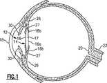
図について説明する。図1は虹彩30によって分離された前眼房12および後眼房14を有する人間の目10の断面図である。後眼房14内には生来の水晶体17を保持する嚢16がある。光は角膜18を透過して水晶体17に入射し、角膜18と水晶体17との協働により目の奥の網膜に向けて合焦される。網膜は視神経22に連絡しており、網膜が捕捉した像が脳に送られることにより像が解釈される。 The figure will be described. FIG. 1 is a cross-sectional view of a human eye 10 having an
生来の水晶体が損傷(例えば、白内障によって混濁)した目においては、生来の水晶体はもはや入射した光を網膜に向け適切に合焦することができず像がぼやける。これを治療するよく知られた手術法においては、損傷した水晶体の摘出、および眼内レンズ、即ちIOLとして知られている図2に示す従来のIOL24のような人工レンズによる代替が伴う。多様なIOLおよび正確にIOLを目にセットする各種方法があるが、本発明は目10の卵形を成す嚢16内部に移植されるIOLに関するものである。この移植方法は当技術分野において、一般に“インザバッグ”手法と呼ばれている。この手術法においては、嚢前面の一部が切除され(キャプスラーヘキシスと呼ばれている)、後被膜16aがそのまま残され毛様体26に支持される。 In eyes where the natural lens is damaged (eg, turbid due to cataracts), the natural lens can no longer properly focus the incident light on the retina and the image is blurred. A well-known surgical procedure for treating this involves the removal of the damaged lens and replacement with an intraocular lens, ie, an artificial lens such as the conventional IOL 24 shown in FIG. 2 known as IOL. Although there are various IOLs and various methods for setting the IOL accurately in the eye, the present invention relates to an IOL that is implanted inside the
このように、IOL手術における“インザバッグ”手法においては、虹彩30後方の後眼房14内の嚢内部に移植される。IOLは摘出された生来の水晶体を模して光を網膜に向けて合焦する中央光学部24a、および中央光学部を嚢内の適切な位置に支持する手段を有している。光学体を支持する一般的な構造体は、光学体の端部から外部に放射状に延びる触覚と呼ばれる弾性構造体である。一般的なIOLにおいては、2つの触覚24b、24cがそれぞれ光学体の反対側に延びている。これ等の触覚は嚢の内側に対し付勢力をもたらし光学体を嚢内の適切な位置に保持するよう湾曲を成している。 As described above, in the “in-the-bag” technique in the IOL operation, the IOL operation is transplanted inside the sac in the
背景技術の項で述べたように、後嚢混濁、即ちPCOとして知られる手術後の好ましくない状況が発生し、それにより移植されたIOLが混濁して適切な光の方向付けおよび合焦ができなくなることがある。主な原因はIOL光学体後方の後嚢における水晶体上皮細胞(LEC)の有糸分裂および転移である。図2に示すように、嚢16の後面16aがIOL光学体24aの背面に接触している。損傷した生来の水晶体を手術によって摘出した際、嚢16内、特にその赤道16b、に多数のLECが残存する可能性があり、これがLEC胚の主な供給源になっている。IOL移植手術の際、嚢からすべてのLECを除去しようとしても殆んど不可能である。LECが少しでも残存していれば、それが増殖して後嚢壁16aに転移する。丸みを帯びた縁部を有するIOLにこの傾向が強く、手術後3年以内に20〜50%の患者が臨床的に明らかなPCOを招来していることが知られている。背景技術の項で述べたように、現在PCOを予防する一般的かつ効果的な方法は後嚢壁16aに鋭く尖った不連続な屈曲を設けることである。 As mentioned in the background section, a posterior capsule turbidity, or an unfavorable post-surgical situation known as PCO, occurs, which causes the transplanted IOL to become turbid and properly direct and focus the light. It may disappear. The main cause is mitosis and metastasis of lens epithelial cells (LEC) in the posterior capsule behind the IOL optic. As shown in FIG. 2, the rear surface 16a of the
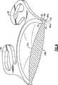
次に、図3〜6は本発明のIOL32の実施の形態例を示す図である。IOL32は前光学面34aおよび背光学面34bを有する中央光学部34を有している。目に移植される際、前光学面34aが角膜18に対向し、背光学面34bが網膜20に対向する。実施の形態例において、合計4つの触覚36〜39が光学部34から延び、嚢の内側に対し付勢力をもたらしIOL32を嚢内の適切な位置に保持するよう形成されている。具体的には、IOLを嚢内部に移植すると、触覚36〜39が嚢内表面に係合するよう形成されている。前記触覚と嚢との係合により付勢力が生じ、IOL光学部34が網膜20に向け後方に湾曲することにより、IOL光学体の背面34bが嚢16の後嚢壁16aの内側に強く押圧される。 Next, FIGS. 3-6 is a figure which shows the example of embodiment of IOL32 of this invention. The
触覚の数および構造は変更可能であり、それらも本発明の範囲に属するものである。また、IOL32は、例えば、PMMA,シリコーン、アクリル、ヒドロゲル、あるいはその化合物など、適切なIOL材料から成ることができる。また、IOL32は(例えば、1つの材料片から光学体および触覚を機械加工した)1ピース型、または(例えば、光学体を形成した後、触覚を光学体に取り付けた)多ピース型とすることができる。好ましい実施の形態例において、以下に詳細に述べるように、眼内使用規格のアクリル・ボタンから1つのピースとしてIOLが旋盤加工される。 The number and structure of haptics can vary and are within the scope of the present invention. Also, the
図3〜6において、IOL光学部34は、前記のように、IOL32を目の嚢に移植したとき、後嚢壁に屈曲を設けることによりPOCを抑制する効果を有する後方に鋭く尖った尖端部40を有する周縁部を有している。尖端部40は頂角“A”、並びに第1および第2面40a、40bによって画成される。頂角“A”は略70〜120度であることが好ましく、略80〜100度であることがより好ましく、略90度であることが最も好ましい。尖端部40の頂点は光軸OAに対し略平行に延びる頂軸AAに位置している。第1面40aは背凹領域42に滑らかに融合し、背凹領域42は背光学面34bに滑らかに融合している。勿論、背光学面34bは患者の視力に寄与し、例えば、球面、非球面、円環、多焦点、遠近調節、およびこれ等の組合せを含む任意の光学構造を有することができる。 3-6, as described above, the IOL
背光学面34bの周縁部は放射状に内側に延びる背凹領域42が直線になり始める図5において符号50pで示す箇所から始まる。 The peripheral edge portion of the back
第2尖端部面40bは鈍角“B”を成して最外周端面44に交差する。この鈍角は略110〜150度であることが好ましく、略120〜140度であることがより好ましく、略130度であることが最も好ましい。このように、最外周端面44は尖端部40の外側に放射状に位置し、光軸OA、従って頂軸AAに対し略平行に延びている。IOL光学部34を患者の目の嚢内に適切に保持するための、触覚36〜39のような1つ以上の触覚が最外周端面44から延びている。図示の実施の形態において、触覚の厚さT1は略0.20〜0.40mmであることが好ましく、略0.25〜0.35mmであることがより好ましく、略0.30mmであることが最も好ましい。触覚の厚さT1は最外周端面44の厚さT2より小さく、厚さT2は略0.25〜0.50mmであることが好ましく、略0.30〜0.40mmであることがより好ましく、略0.37mmであることが最も好ましい。また、触覚は最外周端面44の後方限界44p、即ち、面40bと最外周端面44との交点から離間していることが好ましい。尖端部40によって設けられる尖端部の頂点から触覚までのPCO防壁の高さH1は略0.05〜0.25mmであることが好ましく、略0.10〜0.20mmであることがより好ましく、略0.13mmであることが最も好ましい。The second
前記のように、触覚は目内部におけるIOLの安定化に寄与すると共に、光学部34を後方に湾曲させて尖端部40を後嚢壁16aに湾入させる。安定性の維持およびIOLの前方への湾曲を阻止するため、IOLの前面に前凹領域46が設けられる。この前凹領域46はこの領域と前光学面34aとの交点50aまたはその近傍から外に放射状に延びると共に、前光学面34aに滑らかに融合している。前凹領域46は外に放射状に延び、鈍角“D”を成して前周端面48と交差している。前周端面48は前記光軸OAに対し略直角に延び、一端において最外周端面44と略直角“C”を成し、他端において前凹領域46と鈍角“D”を成している。角度“D”は略120〜160度であることが好ましく、略130〜150度であることがより好ましく、略140度であることが最も好ましい。この前周端面48は任意であり、別の実施の形態においては、前凹領域46が図5の破線に沿って延び、鈍角を成して直接最外周端面44と交差している。 As described above, the tactile sensation contributes to the stabilization of the IOL in the inside of the eye, and the
図示の実施の形態において、前光学面および背光学面34a、34bは何れも凸面である。この実施の形態において、前記寸法はパワーが略10〜30DのIOLに適している。しかし、本発明は双凸面光学体あるいは特定のパワーに限定されるものではない。 In the illustrated embodiment, the front optical surface and the back
好ましい実施の形態において、IOL32がアクリルから成り、眼内使用規格のアクリル・ボタンから1つのピースに旋盤およびフライス加工される。この方法において、アクリル・ボタンがアーバーに固定され、このアーバーが刃具(好ましくはダイヤモンド刃具)を有する旋盤に取り付けられる。前記アーバーが回転している間に尖端部40を有する背光学面34b、背凹領域42、および触覚36〜39の背面となる部分が前記刃具によって形成される。このステップが終了した後、旋盤からアーバーが取り外され、ボタンがアーバーから取り外される。前記ボタンが反転され(背面を下にして)別のアーバーに固定される。このアーバーが旋盤に取り付けられ、回転している間に前光学面34a、前凹領域46、任意の前周端面48、および触覚36〜39の前面となる部分が前記刃具によって形成される。このステップが終了した後、旋盤からアーバーが取り外されフライス盤に回される。フライス工程において、前記アーバーを静止させたまま、切削工具により前記ボタンを貫通して経路が切削され1ピースIOLの完全な外周P(輪郭)が形成される(図3)。IOL32の好ましい実施の形態において、このフライス工程において触覚36〜39の穴36’〜39’も設けられる。 In a preferred embodiment, the
図6は破線で示す従来のIOLに比し、本発明のIOLの領域が小さいことを示している。本発明のIOL32の中央厚CTが従来のIOL32’の中央厚CT’より小さく、前背凹領域46、42によって光学体周縁部の領域が縮小され、尖端部40が形成されている。好ましい実施の形態において、本発明のIOLのCTは+10.00D(ジオプター)〜+30.00Dのレンズに対し、略0.50〜略1.1mmである。従来のIOL32’は3mm未満の切開部に通すことができず、またPCOを抑制または防止する機能を有していない。 FIG. 6 shows that the area of the IOL of the present invention is smaller than the conventional IOL indicated by the broken line. The central thickness CT of the
前背凹領域46、42は互いに対向する位置に設けられ、略同一の半径R1=R2を有していることが好ましく、この半径は0.15〜0.5mmであることが好ましく、略0.20〜0.40mmであることがより好ましく、略0.30mmであることが最も好ましい。R1とR2との間の最小厚T3は略0.10〜0.30mmであることが好ましく、略0.20mmであることが最も好ましい。目内部におけるIOLの安定化を支援する1つ以上の触覚36〜39は最外周端面44の後方限界44pから離間していることが好ましい。このように、前背凹領域46、42によってIOL光学部34の寸法が縮小されてもIOL32の強度および安定性は維持される。これは少なくとも1つには、触覚の厚さT1が縮小されておらず、同様の構造を有する従来のIOLと同等の厚さを有していることである(図6)。更に、前凹領域46と背凹領域42との間の光学体の厚さT3が触覚の厚さT1より小さいことによっても達成される。前凹領域46によりIOL32の前方(即ち、角膜方向)への湾曲が阻止されることによりIOL32の本来の安定性が増すと共に、尖端部40の後嚢壁への湾入が堅持される。これがLECの内部転移の防壁となりPCOが抑制される。また、尖端部40により、IOLの前面側に比し、背面側に材料領域が付加されることにより、背凹領域42とのバランスが保たれ、背凹領域42を設けてもIOLが後方に湾曲すると共に、前記のように光学部34全体の寸法が縮小され3mm未満の切開部に通すことができる。換言すれば、前凹領域46によりIOLが後方に湾曲するよう付勢される一方、尖端部40という背側への追加材料により、背凹領域42によって前方に湾曲するよう付勢されることがない。触覚36〜39と最外周端面44の後方限界44pとの間隔によっても後方湾曲が支援される。更に、前凹領域46と背凹領域42との間の光学体の厚さT3が、IOL本来の強度および安定性に寄与する触覚の厚さT1(前記数値参照)より小さいということによっても達成される。The front
このように、十分小さく3mm未満の切開部に収まり、目内部において安定状態を保持する十分な強度を有し、前記のように実質的にPCOを防止する尖端部を有する独特のIOLおよびその製造方法が提供される。 In this way, a unique IOL having a tip that is small enough to fit within an incision of less than 3 mm, has sufficient strength to remain stable within the eye, and substantially prevents PCO as described above, and its manufacture A method is provided.

12 前眼房
14 後眼房
16 嚢
16a 後嚢壁
17 水晶体
18 角膜
20 網膜
24 従来のIOL
30 虹彩
32 本発明のIOL
34 中央光学部
34a 前光学面
34b 背光学面
36〜39 触覚
40 尖端部
42 背凹部
44 最外周端面
46 前凹部
48 前周端面12
30 Iris
32 IOL of the present invention
34 Central
Claims (33)
Translated fromJapaneseb)前記背光学面に滑らかに融合すると共に該背光学面の外部に放射状に位置する背凹領域、
c)前記前光学面に滑らかに融合すると共に該前光学面の外部に放射状に位置する前凹領域、
d)前記前背凹領域の外部に放射状に位置する最外周端面、および
e)角度“A”、第1面、および第2面によって画成され、前記背光学面の周囲360°にわたり後方に延びる尖端部であって、前記第1面が該尖端部と前記背凹領域との間を連結し、前記第2面が該尖端部と前記最外周端面との間を連結している尖端部
を有して成ることを特徴とする人間の目に移植される眼内レンズ。a) an optical lens having an opposing front optical surface and an optical axis extending from the front optical surface to the back optical surface;
b) a dorsal concave region that fuses smoothly with the back optical surface and is radially located outside the back optical surface;
c) a front concave region that fuses smoothly with the front optical surface and is radially located outside the front optical surface;
d) an outermost peripheral end surface radially located outside the front dorsal concave area, and e) defined by an angle “A”, a first surface, and a second surface, and back 360 ° around the back optical surface. An extended apex, the first surface connecting the apex and the dorsal concave region, and the second surface connecting the apex and the outermost peripheral end An intraocular lens to be implanted in the human eye.
b)前記ボタンに前記眼内レンズの背光学面および尖端部を旋盤加工するステップ、
c)前記ボタンを前記アーバーから取り外し、該ボタンの前記背光学面をアーバーに向け下にして該アーバーに再固定するステップ、および
d)前記ボタンに前記眼内レンズの前光学面を旋盤加工するステップ
の各ステップを有して成る方法によって作製された請求項1記載の眼内レンズ。a) providing a lathe-processable button made of intraocular standard material and securing the button to the arbor;
b) turning the back optical surface and the tip of the intraocular lens on the button;
c) removing the button from the arbor and re-fixing the button back to the arbor with the back optical surface facing the arbor; and d) turning the front optical surface of the intraocular lens to the button. The intraocular lens according to claim 1, produced by a method comprising the steps of:
Applications Claiming Priority (3)
| Application Number | Priority Date | Filing Date | Title |
|---|---|---|---|
| US11/025,405US7569073B2 (en) | 2004-12-29 | 2004-12-29 | Small incision intraocular lens with anti-PCO feature |
| US11/025,405 | 2004-12-29 | ||
| PCT/US2005/046516WO2006071713A1 (en) | 2004-12-29 | 2005-12-21 | Small incision intraocular lens with anti-pco feature |
Publications (3)
| Publication Number | Publication Date |
|---|---|
| JP2008525156A JP2008525156A (en) | 2008-07-17 |
| JP2008525156A5 JP2008525156A5 (en) | 2009-02-12 |
| JP4838267B2true JP4838267B2 (en) | 2011-12-14 |
Family
ID=36215555
Family Applications (1)
| Application Number | Title | Priority Date | Filing Date |
|---|---|---|---|
| JP2007549487AActiveJP4838267B2 (en) | 2004-12-29 | 2005-12-21 | Small incision intraocular lens having anti-PCO function |
Country Status (11)
| Country | Link |
|---|---|
| US (2) | US7569073B2 (en) |
| EP (1) | EP1830746B1 (en) |
| JP (1) | JP4838267B2 (en) |
| KR (1) | KR101276938B1 (en) |
| CN (1) | CN101090679B (en) |
| AU (1) | AU2005322156B2 (en) |
| CA (1) | CA2594513C (en) |
| ES (1) | ES2633262T3 (en) |
| PL (1) | PL1830746T3 (en) |
| TW (1) | TWI380804B (en) |
| WO (1) | WO2006071713A1 (en) |
Cited By (1)
| Publication number | Priority date | Publication date | Assignee | Title |
|---|---|---|---|---|
| JP2012509751A (en)* | 2008-11-26 | 2012-04-26 | アニユー・オプテイクス・インコーポレイテツド | Haptic device for intraocular lens |
Families Citing this family (50)
| Publication number | Priority date | Publication date | Assignee | Title |
|---|---|---|---|---|
| CA2548735C (en) | 2003-12-09 | 2012-11-13 | Advanced Medical Optics, Inc. | Foldable intraocular lens and method of making |
| US7615073B2 (en)* | 2003-12-09 | 2009-11-10 | Advanced Medical Optics, Inc. | Foldable intraocular lens and method of making |
| US7569073B2 (en)* | 2004-12-29 | 2009-08-04 | Bausch & Lomb Incorporated | Small incision intraocular lens with anti-PCO feature |
| RU2332961C1 (en)* | 2007-05-10 | 2008-09-10 | Федеральное государственное учреждение "Межотраслевой научно-технический комплекс "Микрохирургия глаза" имени академика С.Н. Федорова Федерального агентства по здравоохранению и социальному развитию" | Artificial eye lens |
| RU2335259C1 (en)* | 2007-05-10 | 2008-10-10 | Федеральное государственное учреждение "Межотраслевой научно-технический комплекс "Микрохирургия глаза" имени академика С.Н. Федорова Федерального агентства по здравоохранению и социальному развитию" | Artificial eye lens |
| RU2332962C1 (en)* | 2007-05-10 | 2008-09-10 | Федеральное государственное учреждение "Межотраслевой научно-технический комплекс "Микрохирургия глаза" имени академика С.Н. Федорова Федерального агентства по здравоохранению и социальному развитию" | Artificial eye lens |
| US20090088842A1 (en)* | 2007-09-27 | 2009-04-02 | Drew Morgan | Intraocular Lens |
| FR2922096B1 (en)* | 2007-10-16 | 2010-01-08 | Ioltechnologie Production | INTRAOCULAR LENS FOR CAPSULAR BAG |
| RU2353333C1 (en)* | 2007-11-29 | 2009-04-27 | Федеральное государственное учреждение "Межотраслевой научно-технический комплекс "Микрохирургия глаза" имени академика С.Н. Федорова Федерального агентства по высокотехнологичной медицинской помощи" | Intraocular lens implant |
| RU2377964C2 (en)* | 2008-03-19 | 2010-01-10 | Федеральное государственное учреждение "Межотраслевой научно-технический комплекс "Микрохирургия глаза" имени академика С.Н. Федорова Федерального агентства по высокотехнологичной медицинской помощи" | Intraocular lens |
| NL2001503C2 (en)* | 2008-04-21 | 2009-10-22 | Oculentis B V | Intraocular lens. |
| US8167940B2 (en)* | 2008-05-06 | 2012-05-01 | Novartis Ag | Aspheric toric intraocular lens |
| US10010405B2 (en)* | 2008-11-26 | 2018-07-03 | Anew Aol Technologies, Inc. | Haptic devices for intraocular lens |
| US8685087B2 (en)* | 2008-12-11 | 2014-04-01 | Bausch & Lomb Incorporated | Intraocular lens and method of making an intraocular lens |
| JP5420913B2 (en)* | 2009-01-06 | 2014-02-19 | 株式会社ニデック | Intraocular lens |
| US8728158B2 (en)* | 2009-02-09 | 2014-05-20 | Jeffrey C. Whitsett | Exchangeable intraocular lens device and method of use |
| GB2468367B (en)* | 2009-05-27 | 2011-02-16 | See Again Europ Ltd | Intraocular lens systems and methods |
| FR2949966B1 (en)* | 2009-09-11 | 2011-12-09 | Medicontur Orvostechnikai Korlatolt Felelossegu Tarsasag | INTRAOCULAR IMPLANT. |
| US20110245840A1 (en) | 2010-03-31 | 2011-10-06 | Seyboth William J | Intraocular lens injector system |
| US9220590B2 (en) | 2010-06-10 | 2015-12-29 | Z Lens, Llc | Accommodative intraocular lens and method of improving accommodation |
| US8940045B2 (en)* | 2010-11-24 | 2015-01-27 | Santen Pharmaceutical Co., Ltd. | Intraocular lens |
| US11364108B2 (en)* | 2011-09-14 | 2022-06-21 | Investmed Kft. | Intraocular lens for implantation in a ciliary sulcus of an eye |
| US12036111B2 (en)* | 2011-09-14 | 2024-07-16 | Medicontur Holding Ltd. | Method of implantation of an intraocular lens in a ciliary sulcus of an eye |
| FR2979816A1 (en)* | 2011-09-14 | 2013-03-15 | Qmp Holding Gmbh | IMPROVED HAPTIC DEVICE FOR SULCUS IMPLANT |
| CN103211664B (en)* | 2012-01-19 | 2015-06-24 | 爱博诺德(北京)医疗科技有限公司 | Posterior chamber type artificial crystal |
| EP2805694B1 (en)* | 2012-01-19 | 2019-06-26 | Eyebright Medical Technology (Beijing) Co., Ltd. | Posterior chamber-type intraocular lens |
| EP3915519A1 (en) | 2012-01-24 | 2021-12-01 | The Regents of the University of Colorado, a body corporate | Modular intraocular lens designs |
| US9757227B2 (en)* | 2012-04-20 | 2017-09-12 | Hanita Lenses | Intraocular assembly |
| US9364318B2 (en) | 2012-05-10 | 2016-06-14 | Z Lens, Llc | Accommodative-disaccommodative intraocular lens |
| KR102287459B1 (en)* | 2013-08-20 | 2021-08-09 | 텔레온 홀딩 비.브이. | Intraocular lens assembly |
| ES2948036T3 (en)* | 2014-02-18 | 2023-08-30 | Alcon Inc | Apparatus for resection of an intraocular lens |
| KR101629199B1 (en)* | 2014-10-06 | 2016-06-10 | 한국과학기술연구원 | Intraocular lens with fine pattern |
| CA2962895A1 (en) | 2014-12-09 | 2016-06-16 | Novartis Ag | Accommodative, curvature-changing intraocular lenses |
| EP4523656A3 (en) | 2015-01-30 | 2025-05-21 | Alcon Inc. | Modular intraocular lens designs, tools and methods |
| WO2016132185A1 (en)* | 2015-02-16 | 2016-08-25 | Prakhyat ROOP | Optical implantable member |
| CN104720932A (en)* | 2015-03-10 | 2015-06-24 | 北京艾克伦医疗科技有限公司 | Artificial lens capsule and injection type artificial lens including same |
| US10285807B2 (en)* | 2015-04-14 | 2019-05-14 | Z Optics LLC | High definition and extended depth of field intraocular lens |
| CN118873298A (en)* | 2015-11-04 | 2024-11-01 | 克拉维斯塔医疗有限公司 | Modular intraocular lens designs, tools and methods |
| US11045309B2 (en) | 2016-05-05 | 2021-06-29 | The Regents Of The University Of Colorado | Intraocular lens designs for improved stability |
| US10512535B2 (en) | 2016-08-24 | 2019-12-24 | Z Lens, Llc | Dual mode accommodative-disaccomodative intraocular lens |
| GB2565152B (en)* | 2017-08-04 | 2020-06-03 | Rayner Intraocular Lenses Ltd | Intraocular lens |
| AU2018337957A1 (en)* | 2017-09-20 | 2020-04-02 | Clearsight, Llc | Single piece intra-ocular lenses and methods of manufacture thereof |
| WO2019079847A1 (en) | 2017-10-25 | 2019-05-02 | Edward John Milverton | An intraocular lens |
| WO2019126649A1 (en)* | 2017-12-22 | 2019-06-27 | Mayo Foundation For Medical Education And Research | Intraocular lenses |
| CN109199637B (en)* | 2018-03-19 | 2021-05-04 | 广东佳悦美视生物科技有限公司 | Artificial cornea |
| CN115515531A (en)* | 2020-03-11 | 2022-12-23 | 华柏恩视觉研究中心有限公司 | Intraocular lens for reducing peripheral pseudoglare phantom |
| JP7698663B2 (en) | 2020-04-16 | 2025-06-25 | アルコン インコーポレイティド | Multipart IOL with stable IOL base design supporting second optic |
| US12419736B2 (en) | 2020-04-29 | 2025-09-23 | Long Bridge Medical, Inc. | Devices to support and position an intraocular lens within the eye and methods of use |
| US11759309B2 (en) | 2020-04-29 | 2023-09-19 | Long Bridge Medical, Inc. | Devices to support and position an intraocular lens within the eye and methods of use |
| WO2022032143A1 (en)* | 2020-08-07 | 2022-02-10 | Long Bridge Medical, Inc. | Devices to support and position an intraocular lens within the eye and methods of use |
Citations (5)
| Publication number | Priority date | Publication date | Assignee | Title |
|---|---|---|---|---|
| JP2002516708A (en)* | 1998-05-29 | 2002-06-11 | アラーガン・セイルズ・インコーポレイテッド | IOL that suppresses cell growth and reduces glare |
| JP2002542885A (en)* | 1999-04-29 | 2002-12-17 | ボシュ・アンド・ロム・インコーポレイテッド | Intraocular lens |
| JP2003514614A (en)* | 1999-11-24 | 2003-04-22 | アドバンスト メディカル オプティクス, インコーポレーテッド | IOL that suppresses cell growth and reduces flicker |
| WO2004010895A2 (en)* | 2002-07-30 | 2004-02-05 | Rayner Intraocular Lenses Ltd. | Intraocular lens |
| JP2004538086A (en)* | 2001-08-15 | 2004-12-24 | ヒューマンオプティクス アクチェンゲゼルシャフト | Intraocular implant |
Family Cites Families (69)
| Publication number | Priority date | Publication date | Assignee | Title |
|---|---|---|---|---|
| US3996189A (en)* | 1975-04-29 | 1976-12-07 | American Optical Corporation | Optically clear filled silicone elastomers |
| US3996187A (en)* | 1975-04-29 | 1976-12-07 | American Optical Corporation | Optically clear filled silicone elastomers |
| US4190693A (en)* | 1975-06-17 | 1980-02-26 | Rohm And Haas Company | Coating method using compositions comprising acrylic oligomers, high polymers and crosslinkers |
| US4244060A (en)* | 1978-12-01 | 1981-01-13 | Hoffer Kenneth J | Intraocular lens |
| US4418165A (en)* | 1980-06-03 | 1983-11-29 | Dow Corning Corporation | Optically clear silicone compositions curable to elastomers |
| US5074875A (en)* | 1981-10-30 | 1991-12-24 | Anthony Donn | Intraocular-external lens combination system and method of using same |
| US4710197A (en) | 1981-10-30 | 1987-12-01 | Anthony Donn | Intraocular-external lens combination system and method of using same |
| EP0134489A1 (en) | 1983-07-20 | 1985-03-20 | McTigue, John | Intraocular lens |
| EP0391452B1 (en) | 1983-08-30 | 1994-01-05 | Ezekiel Nominees Pty.Ltd. | Intraocular lens implants |
| US4562600A (en)* | 1983-10-18 | 1986-01-07 | Stephen P. Ginsberg | Intraocular lens |
| US4629462A (en)* | 1984-07-13 | 1986-12-16 | Feaster Fred T | Intraocular lens with coiled haptics |
| US4647282A (en)* | 1985-08-27 | 1987-03-03 | Moskovsky Nauchno-Issledovatelsky Institut Mikrokhirurgii Glaza | Material for ocular prosthetics |
| US4868251A (en)* | 1986-12-24 | 1989-09-19 | Allergan, Inc. | Ultraviolet light absorbing silicone compositions |
| FR2668922A1 (en) | 1990-11-14 | 1992-05-15 | Franceschi Francois | CRYSTALLINE IMPLANT OF POSTERIOR CHAMBER. |
| JP2540879Y2 (en)* | 1990-11-30 | 1997-07-09 | 株式会社メニコン | Intraocular lens |
| RU1811395C (en) | 1991-01-08 | 1993-04-23 | Свердловский филиал МНТК "Микрохирургия глаза" | Artificial eye lens implantation method |
| US5171230A (en)* | 1991-11-29 | 1992-12-15 | Medex, Inc. | Fast flush catheter valve |
| US5512609A (en)* | 1992-04-14 | 1996-04-30 | Allergan, Inc. | Reinforced compositions and lens bodies made from same |
| FR2693649B1 (en) | 1992-07-16 | 1994-10-14 | Corneal | Flexible intraocular implant. |
| EP0599457B1 (en)* | 1992-09-28 | 1999-05-19 | Iolab Corporation | Ophthalmic lens with reduced edge glare |
| JP2599319Y2 (en) | 1992-09-30 | 1999-09-06 | ホーヤ・ヘルスケア株式会社 | Intraocular lens |
| US6322589B1 (en)* | 1995-10-06 | 2001-11-27 | J. Stuart Cumming | Intraocular lenses with fixated haptics |
| US5620013A (en)* | 1994-10-21 | 1997-04-15 | American Cyanamid Company | Method for destroying residual lens epithelial cells |
| DE19501444A1 (en) | 1995-01-19 | 1996-07-25 | Morcher Gmbh | Intra ocular two lens system |
| US20020095211A1 (en)* | 1995-05-09 | 2002-07-18 | Craig Young | IOL for reducing secondary opacification |
| US5549670A (en)* | 1995-05-09 | 1996-08-27 | Allergan, Inc. | IOL for reducing secondary opacification |
| US5693094A (en)* | 1995-05-09 | 1997-12-02 | Allergan | IOL for reducing secondary opacification |
| US20050177230A1 (en)* | 1996-08-27 | 2005-08-11 | Craig Young | IOL for reducing secondary opacification |
| GB9520457D0 (en) | 1995-10-06 | 1995-12-06 | Rayner Intraocular Llenses Lim | Intraocular lenses |
| WO1997012564A1 (en)* | 1995-10-06 | 1997-04-10 | Cumming J Stuart | Intraocular lenses with fixated haptics |
| FR2748200B1 (en) | 1996-05-03 | 1998-09-25 | W K Et Associes | FLEXIBLE MONOBLOCK INTRAOCULAR IMPLANT |
| DE19713205C1 (en)* | 1997-03-28 | 1998-05-20 | Gerstel Gmbh | Process and apparatus to prepare sample for gas chromatography |
| DE29710967U1 (en) | 1997-06-17 | 1997-08-28 | Tomey AG, 91058 Erlangen | Flexible intra-eyepiece lens |
| US6277940B1 (en)* | 1997-08-20 | 2001-08-21 | Menicon Co. Ltd | Material for a soft intraocular lens |
| US6326448B1 (en)* | 1997-08-20 | 2001-12-04 | Menicon Co., Ltd. | Soft intraocular lens material |
| US6800091B2 (en)* | 1997-08-20 | 2004-10-05 | Thinoptx, Inc. | Method of using a small incision lens |
| CN1213671A (en)* | 1997-10-07 | 1999-04-14 | 参天制药株式会社 | Four-component copolymer and eye lens formed by same |
| FR2773318B1 (en)* | 1998-01-08 | 2000-03-03 | Georges Baikoff | IMPLANT OF ANTERIOR CHAMBER FOR THE TREATMENT OF THE SEALED EYE |
| FR2776181B1 (en)* | 1998-03-20 | 2000-08-11 | Chauvin Opsia | FLEXIBLE MONOBLOCK INTRAOCULAR LENS |
| US6267784B1 (en)* | 1998-05-01 | 2001-07-31 | Benz Research And Development Corporation | Intraocular lens and haptics made of a copolymer |
| EP0958796B1 (en)* | 1998-05-11 | 2003-10-15 | Tobias Dr. Neuhann | Intraocular lens |
| US6884262B2 (en)* | 1998-05-29 | 2005-04-26 | Advanced Medical Optics, Inc. | Enhanced intraocular lens for reducing glare |
| US6468306B1 (en)* | 1998-05-29 | 2002-10-22 | Advanced Medical Optics, Inc | IOL for inhibiting cell growth and reducing glare |
| US6245106B1 (en)* | 1998-10-29 | 2001-06-12 | Allergan Sales, Inc. | Intraocular lenses made from polymeric compositions and monomers useful in said compositions |
| US6228115B1 (en)* | 1998-11-05 | 2001-05-08 | Bausch & Lomb Surgical, Inc. | Intraocular lenses with improved axial stability |
| US6190410B1 (en)* | 1999-04-29 | 2001-02-20 | Bausch & Lomb Surgical, Inc. | Intraocular lenses |
| US6406494B1 (en)* | 1999-04-30 | 2002-06-18 | Allergan Sales, Inc. | Moveable intraocular lens |
| US6461384B1 (en)* | 1999-06-17 | 2002-10-08 | Bausch & Lomb Incorporated | Intraocular lenses |
| FR2795944B1 (en) | 1999-07-08 | 2001-11-02 | Corneal Ind | INTRAOCULAR IMPLANT |
| US20020087210A1 (en)* | 1999-09-02 | 2002-07-04 | Donald Carrol Stenger | Intraocular |
| US6398809B1 (en)* | 2000-04-12 | 2002-06-04 | Bausch & Lomb Incorporated | Intraocular lens |
| US6555030B1 (en)* | 2000-04-21 | 2003-04-29 | Advanced Medical Optics, Inc. | Method for making an accommodating intraocular lens |
| BR0106643A (en) | 2000-04-21 | 2002-04-09 | Allergan Sales Inc | Method for making an intraocular accommodation lens |
| US6558420B2 (en)* | 2000-12-12 | 2003-05-06 | Bausch & Lomb Incorporated | Durable flexible attachment components for accommodating intraocular lens |
| US6827738B2 (en)* | 2001-01-30 | 2004-12-07 | Timothy R. Willis | Refractive intraocular implant lens and method |
| JP4776813B2 (en)* | 2001-06-12 | 2011-09-21 | ルネサスエレクトロニクス株式会社 | Manufacturing method of semiconductor device |
| US6558419B1 (en)* | 2001-11-08 | 2003-05-06 | Bausch & Lomb Incorporated | Intraocular lens |
| US20030120342A1 (en)* | 2001-12-21 | 2003-06-26 | Green George F. | Intraocular lens |
| WO2003077803A1 (en) | 2002-03-18 | 2003-09-25 | Hanita Lenses Ltd. | Sharp angle intraocular lens optic |
| US20040002757A1 (en)* | 2002-06-27 | 2004-01-01 | Bausch & Lomb Incorporated | Intraocular lens |
| US20040059414A1 (en)* | 2002-09-25 | 2004-03-25 | Green George F. | Intraocular lens |
| JP4974527B2 (en)* | 2003-04-28 | 2012-07-11 | Hoya株式会社 | Integrated intraocular lens and manufacturing method thereof |
| EP1667610A1 (en) | 2003-09-30 | 2006-06-14 | Bausch & Lomb Incorporated | Intraocular lens for inhibiting pco and aco |
| US7553327B2 (en) | 2003-12-04 | 2009-06-30 | The Nice Trust, A Trust Of The Isle Of Man | Accommodating 360 degree sharp edge optic plate haptic lens |
| CA2548735C (en)* | 2003-12-09 | 2012-11-13 | Advanced Medical Optics, Inc. | Foldable intraocular lens and method of making |
| US7615073B2 (en)* | 2003-12-09 | 2009-11-10 | Advanced Medical Optics, Inc. | Foldable intraocular lens and method of making |
| US20050187621A1 (en) | 2004-02-24 | 2005-08-25 | Brady Daniel G. | Foldable unitary intraocular lens |
| DE102004025305A1 (en) | 2004-05-19 | 2005-12-08 | Humanoptics Ag | Accommodatable intraocular lens |
| US7569073B2 (en)* | 2004-12-29 | 2009-08-04 | Bausch & Lomb Incorporated | Small incision intraocular lens with anti-PCO feature |
- 2004
- 2004-12-29USUS11/025,405patent/US7569073B2/ennot_activeExpired - Lifetime
- 2005
- 2005-12-08TWTW94143370Apatent/TWI380804B/enactive
- 2005-12-21EPEP05855127.6Apatent/EP1830746B1/enactiveActive
- 2005-12-21WOPCT/US2005/046516patent/WO2006071713A1/enactiveApplication Filing
- 2005-12-21ESES05855127.6Tpatent/ES2633262T3/enactiveActive
- 2005-12-21JPJP2007549487Apatent/JP4838267B2/enactiveActive
- 2005-12-21PLPL05855127Tpatent/PL1830746T3/enunknown
- 2005-12-21CACA 2594513patent/CA2594513C/enactiveActive
- 2005-12-21AUAU2005322156Apatent/AU2005322156B2/enactiveActive
- 2005-12-21CNCN2005800451772Apatent/CN101090679B/enactiveActive
- 2005-12-21KRKR1020077014741Apatent/KR101276938B1/enactiveActive
- 2009
- 2009-06-30USUS12/494,489patent/US7931686B2/ennot_activeExpired - Lifetime
Patent Citations (5)
| Publication number | Priority date | Publication date | Assignee | Title |
|---|---|---|---|---|
| JP2002516708A (en)* | 1998-05-29 | 2002-06-11 | アラーガン・セイルズ・インコーポレイテッド | IOL that suppresses cell growth and reduces glare |
| JP2002542885A (en)* | 1999-04-29 | 2002-12-17 | ボシュ・アンド・ロム・インコーポレイテッド | Intraocular lens |
| JP2003514614A (en)* | 1999-11-24 | 2003-04-22 | アドバンスト メディカル オプティクス, インコーポレーテッド | IOL that suppresses cell growth and reduces flicker |
| JP2004538086A (en)* | 2001-08-15 | 2004-12-24 | ヒューマンオプティクス アクチェンゲゼルシャフト | Intraocular implant |
| WO2004010895A2 (en)* | 2002-07-30 | 2004-02-05 | Rayner Intraocular Lenses Ltd. | Intraocular lens |
Cited By (1)
| Publication number | Priority date | Publication date | Assignee | Title |
|---|---|---|---|---|
| JP2012509751A (en)* | 2008-11-26 | 2012-04-26 | アニユー・オプテイクス・インコーポレイテツド | Haptic device for intraocular lens |
Also Published As
| Publication number | Publication date |
|---|---|
| AU2005322156B2 (en) | 2011-06-23 |
| WO2006071713A1 (en) | 2006-07-06 |
| US7569073B2 (en) | 2009-08-04 |
| US7931686B2 (en) | 2011-04-26 |
| ES2633262T3 (en) | 2017-09-20 |
| KR101276938B1 (en) | 2013-06-19 |
| CA2594513A1 (en) | 2006-07-06 |
| KR20070092243A (en) | 2007-09-12 |
| CA2594513C (en) | 2011-08-02 |
| TWI380804B (en) | 2013-01-01 |
| EP1830746B1 (en) | 2017-07-05 |
| US20090265000A1 (en) | 2009-10-22 |
| CN101090679A (en) | 2007-12-19 |
| US20060142855A1 (en) | 2006-06-29 |
| TW200624100A (en) | 2006-07-16 |
| AU2005322156A1 (en) | 2006-07-06 |
| PL1830746T3 (en) | 2018-01-31 |
| EP1830746A1 (en) | 2007-09-12 |
| CN101090679B (en) | 2012-12-19 |
| JP2008525156A (en) | 2008-07-17 |
Similar Documents
| Publication | Publication Date | Title |
|---|---|---|
| JP4838267B2 (en) | Small incision intraocular lens having anti-PCO function | |
| KR100879833B1 (en) | Intraocular lens | |
| US20040002757A1 (en) | Intraocular lens | |
| JP2005507286A (en) | Intraocular lens with angled edges to prevent posterior capsule opacification | |
| JP2006500181A (en) | Intraocular lens | |
| US20070027539A1 (en) | Intaocular lens for inhibiting pco and aco | |
| US20030120342A1 (en) | Intraocular lens | |
| US10575943B2 (en) | Vision correction systems and methods for using an intraocular lens enclosed in an inner capsulated bag | |
| HK1108356A (en) | Intraocular lens with small incision and anti-pco feature | |
| HK1108356B (en) | Intraocular lens with small incision and anti-pco feature | |
| KR20060092228A (en) | Intraocular Lens Prevents Capsular Capsular Turbidity (PCO) and Capsular Capsular Turbidity (ACO) | |
| HK1068244B (en) | Intraocular lens |
Legal Events
| Date | Code | Title | Description |
|---|---|---|---|
| A521 | Request for written amendment filed | Free format text:JAPANESE INTERMEDIATE CODE: A523 Effective date:20081218 | |
| A621 | Written request for application examination | Free format text:JAPANESE INTERMEDIATE CODE: A621 Effective date:20081218 | |
| A131 | Notification of reasons for refusal | Free format text:JAPANESE INTERMEDIATE CODE: A131 Effective date:20110201 | |
| A521 | Request for written amendment filed | Free format text:JAPANESE INTERMEDIATE CODE: A523 Effective date:20110502 | |
| TRDD | Decision of grant or rejection written | ||
| A01 | Written decision to grant a patent or to grant a registration (utility model) | Free format text:JAPANESE INTERMEDIATE CODE: A01 Effective date:20110830 | |
| A01 | Written decision to grant a patent or to grant a registration (utility model) | Free format text:JAPANESE INTERMEDIATE CODE: A01 | |
| A61 | First payment of annual fees (during grant procedure) | Free format text:JAPANESE INTERMEDIATE CODE: A61 Effective date:20110929 | |
| FPAY | Renewal fee payment (event date is renewal date of database) | Free format text:PAYMENT UNTIL: 20141007 Year of fee payment:3 | |
| R150 | Certificate of patent or registration of utility model | Ref document number:4838267 Country of ref document:JP Free format text:JAPANESE INTERMEDIATE CODE: R150 Free format text:JAPANESE INTERMEDIATE CODE: R150 | |
| R250 | Receipt of annual fees | Free format text:JAPANESE INTERMEDIATE CODE: R250 | |
| R250 | Receipt of annual fees | Free format text:JAPANESE INTERMEDIATE CODE: R250 | |
| R250 | Receipt of annual fees | Free format text:JAPANESE INTERMEDIATE CODE: R250 | |
| R250 | Receipt of annual fees | Free format text:JAPANESE INTERMEDIATE CODE: R250 | |
| R250 | Receipt of annual fees | Free format text:JAPANESE INTERMEDIATE CODE: R250 | |
| R250 | Receipt of annual fees | Free format text:JAPANESE INTERMEDIATE CODE: R250 | |
| R250 | Receipt of annual fees | Free format text:JAPANESE INTERMEDIATE CODE: R250 | |
| R250 | Receipt of annual fees | Free format text:JAPANESE INTERMEDIATE CODE: R250 | |
| R250 | Receipt of annual fees | Free format text:JAPANESE INTERMEDIATE CODE: R250 | |
| R250 | Receipt of annual fees | Free format text:JAPANESE INTERMEDIATE CODE: R250 | |
| R250 | Receipt of annual fees | Free format text:JAPANESE INTERMEDIATE CODE: R250 |