JP4838265B2 - Electronic device including optical fiber cable and method of forming the same - Google Patents
Electronic device including optical fiber cable and method of forming the sameDownload PDFInfo
- Publication number
- JP4838265B2 JP4838265B2JP2007546627AJP2007546627AJP4838265B2JP 4838265 B2JP4838265 B2JP 4838265B2JP 2007546627 AJP2007546627 AJP 2007546627AJP 2007546627 AJP2007546627 AJP 2007546627AJP 4838265 B2JP4838265 B2JP 4838265B2
- Authority
- JP
- Japan
- Prior art keywords
- housing
- fiber optic
- optic cable
- optical
- electronic component
- Prior art date
- Legal status (The legal status is an assumption and is not a legal conclusion. Google has not performed a legal analysis and makes no representation as to the accuracy of the status listed.)
- Expired - Fee Related
Links
Images


Classifications
- H—ELECTRICITY
- H04—ELECTRIC COMMUNICATION TECHNIQUE
- H04M—TELEPHONIC COMMUNICATION
- H04M1/00—Substation equipment, e.g. for use by subscribers
- H04M1/02—Constructional features of telephone sets
- H04M1/0202—Portable telephone sets, e.g. cordless phones, mobile phones or bar type handsets
- H04M1/026—Details of the structure or mounting of specific components
- H04M1/0264—Details of the structure or mounting of specific components for a camera module assembly
- H—ELECTRICITY
- H04—ELECTRIC COMMUNICATION TECHNIQUE
- H04B—TRANSMISSION
- H04B1/00—Details of transmission systems, not covered by a single one of groups H04B3/00 - H04B13/00; Details of transmission systems not characterised by the medium used for transmission
- H04B1/38—Transceivers, i.e. devices in which transmitter and receiver form a structural unit and in which at least one part is used for functions of transmitting and receiving
- H04B1/3827—Portable transceivers
- H04B1/3833—Hand-held transceivers
- H—ELECTRICITY
- H04—ELECTRIC COMMUNICATION TECHNIQUE
- H04M—TELEPHONIC COMMUNICATION
- H04M1/00—Substation equipment, e.g. for use by subscribers
- H04M1/02—Constructional features of telephone sets
- H04M1/0202—Portable telephone sets, e.g. cordless phones, mobile phones or bar type handsets
- H04M1/0206—Portable telephones comprising a plurality of mechanically joined movable body parts, e.g. hinged housings
- H04M1/0208—Portable telephones comprising a plurality of mechanically joined movable body parts, e.g. hinged housings characterized by the relative motions of the body parts
- H04M1/0214—Foldable telephones, i.e. with body parts pivoting to an open position around an axis parallel to the plane they define in closed position
- H04M1/0216—Foldable in one direction, i.e. using a one degree of freedom hinge
- H04M1/0218—The hinge comprising input and/or output user interface means
Landscapes
- Engineering & Computer Science (AREA)
- Signal Processing (AREA)
- Computer Networks & Wireless Communication (AREA)
- Telephone Set Structure (AREA)
- Optical Couplings Of Light Guides (AREA)
Description
Translated fromJapanese本発明は、電子装置に関し、特に、信号送信ケーブルを含む電子装置に関する。 The present invention relates to an electronic device, and more particularly to an electronic device including a signal transmission cable.
携帯無線電話のようなパーソナル電子装置の製造業者及び設計者は、多くの場合、信頼性及び性能を維持し、製造コストを低減する一方で、装置全体の寸法を縮小しようと努める。一般に、そのような電子装置の種々の構成要素は、構成要素間で信号又はデータを転送するにあたり互いに動作自在に接続される。場合によっては、構成要素間で高いデータ転送速度が求められる。多数の電気導体を使用することにより、この必要条件が満たされることもある。例えば、構成要素間に多数のリード線を設けるために、複数の専用ワイヤ又は可撓性配線テープが採用されてもよい。 Manufacturers and designers of personal electronic devices, such as portable radiotelephones, often strive to reduce overall device dimensions while maintaining reliability and performance, reducing manufacturing costs. Generally, the various components of such electronic devices are operably connected to one another in transferring signals or data between the components. In some cases, a high data transfer rate is required between components. This requirement may be met by using multiple electrical conductors. For example, multiple dedicated wires or flexible wiring tape may be employed to provide multiple leads between components.
しかし、特に、新たな装置が追加されることによってデータ転送速度が増すと、それらのコネクタは、空間条件、信頼性及び信号容量に関して困難な問題を生じる。 However, especially as new devices are added to increase the data transfer rate, these connectors present difficult problems with respect to spatial conditions, reliability and signal capacity.
本発明の実施形態によれば、ハンドヘルドパーソナル電子装置は、ハンドヘルド装置ハウジングを含む。電子構成要素は、ハンドヘルド装置ハウジングの中に配置される。光ファイバケーブルは、ハンドヘルド装置ハウジング内を引き回され、光ファイバケーブルを介する電子構成要素への光信号の送信及び/又は電子構成要素からの光信号の送信を可能にするために、電子構成要素に動作自在に接続される。装置は、移動無線通信装置であってもよい。 According to an embodiment of the present invention, a handheld personal electronic device includes a handheld device housing. The electronic component is disposed in the handheld device housing. The fiber optic cable is routed within the handheld device housing to allow transmission of optical signals to and / or from the electronic components via the fiber optic cable. Is operably connected to. The device may be a mobile radio communication device.
本発明の別の実施形態によれば、移動電子装置は、移動装置ハウジングを含む。光受信機及び光送信機のうち少なくとも一方を含む第1の信号変換器は、移動装置ハウジングの中及び/又は上に配置される。光受信機及び光送信機のうち少なくとも一方を含む第2の信号変換器は、移動装置ハウジングの中及び/又は上に配置される。光ファイバケーブルを介する第1の信号変換器と第2の信号変換器との間の光信号の送信を可能にするために、光ファイバケーブルは、第1の信号変換器と第2の信号変換器とを動作自在に接続する。光ファイバケーブルは、移動装置ハウジングの中及び/又は上に配置される。装置は、無線通信装置であってもよい。 According to another embodiment of the invention, the mobile electronic device includes a mobile device housing. A first signal converter including at least one of an optical receiver and an optical transmitter is disposed in and / or on the mobile device housing. A second signal converter including at least one of an optical receiver and an optical transmitter is disposed in and / or on the mobile device housing. In order to allow transmission of an optical signal between the first signal converter and the second signal converter via the fiber optic cable, the fiber optic cable includes a first signal converter and a second signal converter. The instrument is operably connected. The fiber optic cable is disposed in and / or on the mobile device housing. The device may be a wireless communication device.
本発明の別の実施形態によれば、電子装置は、第1のハウジングと、第1のハウジングに運動自在に結合された第2のハウジングとを含む装置ハウジング構体を含む。光ファイバケーブルは、第1のハウジングと第2のハウジングとの間に延出する。光ファイバケーブルは、光ファイバケーブルを介する第1のハウジングと第2のハウジングとの間の光信号の送信を可能にする。装置ハウジング構体は、第1のハウジングと第2のハウジングとを回動自在に結合するヒンジを含んでもよく、光ファイバケーブルは、ヒンジを跨いで延出する。 In accordance with another embodiment of the present invention, an electronic device includes a device housing assembly that includes a first housing and a second housing movably coupled to the first housing. The fiber optic cable extends between the first housing and the second housing. The fiber optic cable allows transmission of optical signals between the first housing and the second housing via the fiber optic cable. The apparatus housing assembly may include a hinge that rotatably couples the first housing and the second housing, and the optical fiber cable extends across the hinge.
本発明の別の実施形態によれば、電子装置は、装置ハウジングと、装置ハウジングに固着された光ファイバケーブルとを含む。光ファイバケーブルは、装置ハウジングに埋め込まれてもよい。 According to another embodiment of the present invention, an electronic device includes a device housing and a fiber optic cable secured to the device housing. The fiber optic cable may be embedded in the device housing.
本発明の方法の実施形態によれば、電子装置を形成する方法は、装置ハウジングに光ファイバケーブルを埋め込むことを含む。方法は、光ファイバケーブルの周囲にハウジングを成形することを含んでもよい。 According to a method embodiment of the present invention, a method of forming an electronic device includes embedding a fiber optic cable in a device housing. The method may include molding a housing around the fiber optic cable.
以下に、添付の図面を参照して、本発明を更に詳細に説明する。添付の図面には、本発明の実施形態が示される。図中、明確な図示を目的として、領域又は特徴形状の相対的な大きさが誇張して示される場合がある。しかし、本発明は、多くの異なる形態で実現されてもよく、本明細書中で説明される実施形態に限定されると解釈されるべきではない。それらの実施形態は、本開示が徹底的且つ完全となるように提供され、本発明の範囲を余すところなく当業者に伝達する。 Hereinafter, the present invention will be described in more detail with reference to the accompanying drawings. In the accompanying drawings, embodiments of the invention are shown. In the drawings, the relative sizes of regions or feature shapes may be exaggerated for the purpose of clear illustration. However, the present invention may be implemented in many different forms and should not be construed as limited to the embodiments set forth herein. These embodiments are provided so that this disclosure will be thorough and complete, and will fully convey the scope of the invention to those skilled in the art.
ある要素が別の要素に「結合される」又は「接続される」と表現されるとき、その要素は、別の要素に直接結合又は直接接続されるか、あるいはそれらの要素の間に介在する要素が存在してもよいことはいうまでもない。これに対し、ある要素が別の要素に「直接結合される」又は「直接接続される」と表現される場合には、介在する要素は存在しない。全ての図を通して、同様の要素には、同一の図中符号が付される。本明細書中で使用される用語「及び/又は」は、関連して挙げられる項目のうち1つ以上の項目の任意の組合せ及び全ての組合せを含む。 When an element is described as “coupled” or “connected” to another element, the element is directly coupled to or directly connected to another element, or intervening between those elements It goes without saying that elements may be present. On the other hand, when an element is expressed as “directly coupled” or “directly connected” to another element, there are no intervening elements present. Throughout all the drawings, the same elements are denoted by the same reference numerals. The term “and / or” as used herein includes any and all combinations of one or more of the associated listed items.
更に、「下」、「下方」、「下部」、「上方」、「上部」などの空間的相対関係に関連する用語は、本明細書中において、図に示されるような1つの要素又は特徴形状と別の要素又は特徴形状との関係を説明するために、説明の便宜上使用される。空間的相対関係に関連する用語は、図示される向きの規定に加えて、使用中又は動作中の装置の様々に異なる向きを含むことが意図される。例えば、図中の装置が反転された場合、他の要素又は特徴形状の「下」又は「下方」にあると説明された要素は、他の要素又は特徴形状の「上方」の向きになるであろう。従って、例として挙げた用語「下」は、上及び下の双方の向きを含むことができる。装置は、それ以外の向き(90°回転された向き又はその他の向き)であってもよく、本明細書中で使用される空間的相対関係に関する用語も、それに従って解釈されるものとする。 In addition, terms relating to spatial relatives such as “lower”, “lower”, “lower”, “upper”, “upper” are used herein to refer to a single element or feature as shown in the figures. It is used for convenience of description to explain the relationship between the shape and another element or feature shape. Terminology related to spatial relatives is intended to include different orientations of the device in use or in operation in addition to the orientation definition shown. For example, if the device in the figure is flipped, an element described as being “down” or “down” of another element or feature will be in an “up” orientation of the other element or feature. I will. Thus, the example term “bottom” can include both top and bottom orientations. The device may be in any other orientation (90 ° rotated orientation or other orientation), and the terms relating to spatial relationships used herein shall be interpreted accordingly.
簡潔且つ/又は明瞭にするために、周知の機能又は構成は、詳細に説明されなくてもよい。 Well-known functions or constructions may not be described in detail for brevity and / or clarity.
本明細書中で使用される表現「及び/又は」は、関連して挙げられる項目のうち1つ以上の項目の任意の組合せ及び全ての組合せを含む。 As used herein, the expression “and / or” includes any and all combinations of one or more of the associated listed items.
本明細書中で使用される用語は、特定の実施形態を説明する目的のためだけに使用され、本発明を限定することを意図したものではない。本明細書中で使用される単数形「1つの(a, an)」及び「その(the)」は、文脈上、明確な指示がない限り、複数形も同様に含むことが意図される。更に、用語「具備する(comprise)」及び/又は「具備している(comprising)」が本明細書中で使用される場合、それは、挙げられた特徴、数字、ステップ、動作、要素及び/又は構成要素の存在を指定するが、1つ以上の他の特徴、数字、ステップ、動作、要素、構成要素及び/又はそれらのグループの存在又は追加を除外するものではないことはいうまでもない。 The terminology used herein is used for the purpose of describing particular embodiments only and is not intended to be limiting of the invention. As used herein, the singular forms “a, an” and “the” are intended to include the plural forms as well, unless the context clearly indicates otherwise. Furthermore, where the terms “comprise” and / or “comprising” are used herein, they may be listed features, numbers, steps, acts, elements and / or Although the presence of a component is specified, it will be understood that it does not exclude the presence or addition of one or more other features, numbers, steps, actions, elements, components and / or groups thereof.
特に規定されない限り、本明細書中で使用される全ての用語(技術用語及び科学用語を含む)は、本発明が属する分野の当業者により一般に理解されているような意味と同一の意味を有する。更に、一般に使用されている辞書において定義されるような用語は、関連技術に沿った意味合いと一致する意味を有するものとして解釈されるべきであり、特に規定がない限り、理想化された意味又は過度に形式的な意味で解釈されるものはない。 Unless defined otherwise, all terms used herein (including technical and scientific terms) have the same meaning as commonly understood by one of ordinary skill in the art to which this invention belongs. . Furthermore, terms as defined in commonly used dictionaries should be construed as having a meaning consistent with the meaning in line with the related art, and unless otherwise specified, an idealized meaning or Nothing is interpreted in an overly formal sense.
本明細書中で使用される用語「電子構成要素」は、受動的な電気コネクタなどとは対照的に、能動的装置を意味する。電子構成要素は、プロセッサを含んでもよい。 As used herein, the term “electronic component” refers to an active device as opposed to a passive electrical connector or the like. The electronic component may include a processor.
以下に、図1〜図10を参照して、本発明の実施形態を説明する。本発明の実施形態は、電子構成要素間で信号を送信するための光ファイバケーブルが組込まれた電子装置を提供する。 Hereinafter, an embodiment of the present invention will be described with reference to FIGS. Embodiments of the present invention provide an electronic device incorporating a fiber optic cable for transmitting signals between electronic components.
以下に、本発明のいくつかの実施形態による光ファイバケーブルを含む電子装置の概略図及びブロック図を参照して、本発明を説明する。本明細書中、電子装置は、図1〜図7の移動端末100などの移動無線通信端末の一部として含まれるものとして説明されるが、本発明の実施形態はこの構成に限定されない。以下に説明するように、本発明の種々の面は、本発明の範囲から逸脱することなく、例えば無線通信端末ではない又はポータブル電子装置ではない移動装置を含めた他の種類の装置に組込まれてもよい。 The invention will now be described with reference to schematic and block diagrams of electronic devices including fiber optic cables according to some embodiments of the invention. In the present specification, the electronic device is described as being included as a part of a mobile wireless communication terminal such as the
そこで図1を参照すると、本発明の実施形態に従った無線電話通信システムが示される。無線電話通信システムは、移動無線通信端末100と、無線通信網24の一部である基地局トランシーバとを含む。本発明のいくつかの実施形態においては、通信網24は、セルラネットワークにおける個々のセルを規定する無線トランシーバを含む基地局トランシーバを含む。基地局トランシーバは、無線リンクプロトコルを使用して、セル内の移動端末100及び他の移動端末と通信する。本発明のいくつかの実施形態においては、無線通信網を規定するために、例えば移動交換局及び他の装置を介して、多数の基地局トランシーバが接続されてもよいことはいうまでもない。 Referring now to FIG. 1, a radiotelephone communication system according to an embodiment of the present invention is shown. The radiotelephone communication system includes a mobile
移動端末100は、ポータブルハウジング構体110を含む。移動端末100は、マンマシンインタフェース(MMI)26、ディスプレイ28、スピーカ32、マイクロホン34、トランシーバ36、並びにアプリケーション情報及びパラメータを含むメモリ38を含んでもよく、これらの構成要素はいずれも、プロセッサ42と通信してもよい。MMI26は、例えば、キーボード/キーパッドを含んでもよい。更に、本発明の実施形態による移動端末100は、同様にプロセッサ42と通信するデジタルカメラモジュール144を更に含んでもよい。プロセッサ42は、例えば、任意の市販のマイクロプロセッサ又はカスタムマイクロプロセッサであってもよい。 The
トランシーバ36は、通常、アンテナ48を介して通信網24へ出力無線周波数信号を送信する送信機回路44と、アンテナ48を介して通信網24から音声及びデータ信号などの入力無線周波数信号を受信する受信機回路46とを含む。アンテナ48は、本発明の範囲から逸脱することなく、埋め込みアンテナ、伸縮自在のアンテナ又は当業者に周知の任意のアンテナのいずれであってもよい。移動端末100と通信網24との間で送信される無線周波数信号は、第三者又は通信先との間の通信を確立させ且つ維持するために使用されるトラフィック信号及び制御信号(例えば、着信に対するページング信号/メッセージ)の双方を含んでもよい。プロセッサ42は、カメラモジュール144を使用する画像の撮像及び処理を含めた移動端末100の種々の機能を支援してもよい。 The
以上説明した移動端末100の構成要素は、従来の多くの移動端末に含まれており、それらの機能性は、一般に当業者に周知である。本明細書中で使用される用語「ポータブル電子装置」又は「移動端末」は、マルチラインディスプレイを含む又は含まない携帯電話;携帯無線電話をデータ処理能力、ファクシミリ能力及びデータ通信能力と組み合わせてもよいパーソナル通信システム(PCS)端末;無線電話、ページャ、インターネット/イントラネットアクセス、ウェブブラウザ、オーガナイザ、カレンダー及び/又は全地球測位システム(GPS)受信機を含むことができるパーソナルデータアシスタント(PDA);ゲーム機、オーディオビデオプレーヤ、並びに無線電話トランシーバを含んでもよい従来のラップトップコンピュータ及び/又はパームトップポータブルコンピュータを含んでもよい。 The components of the
いくつかの実施形態によれば、図2及び図3に示されるように、移動端末100は、ハンドヘルド(ポータブル)移動端末である。「ハンドヘルド移動端末」というとき、それは、移動端末の外寸が、典型的な操作者が片手で使用するように適合され且つそれに適することを意味する。いくつかの実施形態によれば、ハンドヘルド移動端末の総体積は、約200cc未満である。いくつかの実施形態によれば、ハンドヘルド端末の総体積は、約150cc未満である。いくつかの実施形態によれば、ハンドヘルド移動端末の総体積は、約20〜150ccである。いくつかの実施形態によれば、ハンドヘルド移動端末100の寸法は、いずれも約200mmを超えない。 According to some embodiments, as shown in FIGS. 2 and 3, the
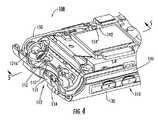
ハウジング構体110を更に詳細に説明する。ハウジング構体110は、ヒンジ112により回動自在に接合された下部ハウジング又は主ハウジング120と上部ハウジング130とを含む。ハウジング120、130は、図2、図4及び図5に示されるような閉鎖位置と図3に示されるような開放位置との間で、ヒンジ112に関して相対的に回動自在である。ハウジング構体110の構成は、一般に、「クラムシェルハウジング」と呼ばれる。クラムシェルハウジングを有するハンドヘルド無線通信端末は、一般に、「フリップ電話」と呼ばれる。 The
ハウジング120は、内部空洞122と、ピボット延長部124Aを有するヒンジ部分124とを規定する。カメラ開口部126は、ヒンジ部分124に規定される。ハウジング130は、内部空洞132を規定し、ヒンジ部分134を有する。ヒンジ部分124、134は、協働自在に係合して、ハウジング120、130を運動自在に結合するヒンジ112を形成する。 The
ハウジング120、130は、ポリスチレンなどのポリマー材料から形成されてもよい。その代わりに又はそれに加えて、ハウジング120、130は、金属などの他の任意の適切な材料から形成されてもよい。ハウジング120、130は成形されてもよく、それぞれ、複数の部品から組立てられてもよい。 The
図3〜図5に示されるように、プリント配線基板(PWB)又はプリント回路基板(PCB)140は、下部ハウジング120の空洞部122に配置される。PCB140は、例えばプロセッサ42の全て又は一部を含んでもよい。ディスプレイ28は、上部ハウジング130に装着される。プリント配線基板又はプリント回路基板(PCB)142は、上部ハウジング130の空洞部132に配置される。PCB142は、ディスプレイ28に接続され、ディスプレイ28を制御するように動作可能である。PCB142は、ディスプレイ28と関連するプロセッサを含んでもよい。ディスプレイ28は、例えば液晶ディスプレイ(LCD)であってもよい。 As illustrated in FIGS. 3 to 5, the printed wiring board (PWB) or the printed circuit board (PCB) 140 is disposed in the cavity 122 of the
光ファイバケーブル150は、PCB140からPCB142まで延出する。特に、光ファイバケーブル150は、下部ハウジング120の空洞部122を通り、ヒンジ112を跨ぎ、上部ハウジング130の空洞部132を通過する。光ファイバケーブルは可撓性であり、図示されるように、ヒンジ112の中で(例えば、ピボット延長部124Aの周囲に)コイル状に収納されてもよい。 The
光ファイバケーブル150は、光信号に対して導波管として機能する。光信号は、光データ信号であってもよい。信号は、例えばデジタル信号及び/又はアナログ信号を実現する変調光であってもよい。信号は、例えば周波数及び/又は輝度が変化してもよい。信号変換器152は、PCB140に装着され、PCB140に電気的に接続される。信号変換器154は、PCB142に装着され、PCB142に電気的に接続される。信号変換器152、154は、それぞれ対応するPCB140、142にはんだ付けされてもよい。その代わりに又はそれに加えて、信号変換器152、154は、それぞれ対応するPCB140、142に埋め込まれてもよい。信号変換器152、154は、光ファイバインタフェースモジュールであってもよい。信号変換器152は、PCB140からの電気アナログ出力信号又は電気デジタル出力信号を対応する光信号に符号化又は変換する光送信機を含む。光信号は、光ファイバケーブル150を介して信号変換器154へ送信される。信号変換器154は、受信した光信号を電気アナログ入力信号又は電気デジタル入力信号に復号化又は変換する。それらの入力信号は、信号変換器152に供給された当初の電気信号と同一又はほぼ同一であってもよい。 The
いくつかの実施形態によれば、双方向信号通信を可能にするために、信号変換器152、154が光受信機及び光送信機として動作できるように、信号変換器152、154は、それぞれ光ファイバトランシーバ又は光トランシーバである。光信号を発生するために、光送信機は、発光ダイオード(LED)又はレーザーダイオードを採用してもよい。光信号を検出するために、光受信機は、フォトダイオード(例えば、PIN型又はアバランシェ型)を採用してもよい。信号変換器152、154に対する適切な光トランシーバ、光受信機及び光送信機は、日本のStanley Electric Co., Ltd.より入手可能である。 According to some embodiments, the
いくつかの実施形態によれば、図7に最も明瞭に示されるように、光ファイバケーブル150は、コア150Aと、コアを取り囲むクラッド層150Bと、クラッド層150Bを取り囲むバッファ層又は被覆膜150Cとを含む。本明細書中で説明されるような光ファイバケーブルの動作は、当業者には理解されるであろう。一般に、コア150Aを通過した光がクラッド層150Bにより反射されてコア150Aに戻るように、クラッド層150Bの屈折率はコア150Aの屈折率より低い。 According to some embodiments, as best shown in FIG. 7, the
いくつかの実施形態によれば、コア150Aは、約1〜8mmの公称外径を有する。いくつかの実施形態によれば、クラッド層150Bは、約1〜15mmの公称外径を有する。 According to some embodiments, the
コア150Aは、プラスチック、あるいはポリメチル‐メタクリレート(PMMA)樹脂、ポリスチレン又はポリカーボネートなどのポリマー材料から形成されてもよい。クラッド層150Bは、プラスチック又はフッ化ポリマーなどのポリマー材料から形成されてもよい。バッファ層150Cは、プラスチック、あるいはポリエチレン、PVC又はナイロンなどのポリマー材料から形成されてもよい。あるいは、コア150A及びクラッド層150Bは、ガラスから形成されてもよい。コアがプラスチックである光ファイバケーブルは、強度、信号容量及び信号劣化/損失に関する条件に適合し、価格及び可撓性の点で好都合であろう。 The
別の被覆膜又は外被(図示せず)が、バッファ層150Cの周囲に塗布されてもよい。コア150A及び/又はクラッド層150Bは、複数のセグメント又は部分を含んでもよい。いくつかの実施形態によれば、光ファイバケーブルは、マルチモード光ファイバケーブルである。 Another coating or jacket (not shown) may be applied around the buffer layer 150C. The
ハウジング110及び光ファイバケーブル150は、光ファイバケーブル150のどの部分も、光ファイバケーブル150の最小曲げ半径より小さい曲げ半径で曲げられることのないように、相対的に配置され且つ構成される。最小曲げ半径は、ファイバを損傷せずにケーブルを曲げることができる最小の半径である。光ファイバケーブル150のどの部分をも曲げすぎることなく、ハウジング120、130のヒンジ運動の範囲に対応するために、光ファイバケーブル150に余分の長さが与えられてもよく、ハウジング110は、例えばヒンジ領域に膨張容積を与えられてもよい。いくつかの実施形態によれば、光ファイバケーブル150は、約2分の1インチ以下の最小曲げ半径を有する。いくつかの実施形態によれば、光ファイバケーブル150は、約4分の1インチ以下の最小曲げ半径を有する。いくつかの実施形態によれば、光ファイバケーブル150は、光ファイバケーブル150の直径の3倍以下の最小曲げ半径を有する。 The
ケーブル150として適切な光ファイバケーブルは、日本のMitsubishi Rayon Co., Ltd.より入手可能なGK-20プラスチック光ファイバ(適切なプラスチックバッファ層又は外皮を含み、例えばGH2001又はGH2002ケーブル)を含んでもよい。光ファイバケーブル150は一例であり、本発明の実施形態に従って他の構成の光ファイバケーブルが採用されてもよいことは、当業者には理解されるであろう。 A suitable fiber optic cable as
図3及び図6を参照すると、光ファイバケーブル160は、PCB140(又は別のPCB又は他の電子構成要素)をカメラモジュール144に動作自在に接続するために採用されてもよい。カメラモジュール144は、レンズ144A及びセンサユニット144Bを含む。 With reference to FIGS. 3 and 6, a
センサユニット144Bは、イメージセンサ(例えば、電荷結合素子(CCD)又は相補型金属酸化膜半導体(CMOS))を含み、これは、バイエルパターンセンサであってもよい。イメージセンサは、画素のアレイと、イメージセンサから生データを読込む読出し電子回路(例えば、プロセッサ)及びアナログ/デジタル変換器(ADC)とを含んでもよい。イメージセンサは、生データを処理、修正、変換及び/又は圧縮するように機能するCPU又はプロセッサを更に含んでもよい。プロセッサは、生データをRGBデータ及び/又はYUVデータに変換するように動作してもよい。プロセッサは、データを(例えば、jpegフォーマットに)圧縮するように動作する符号器及び/又は復号器(コーデック)を更に含んでもよい。しかし、本発明のいくつかの実施形態によれば、センサユニット144Bは、生データを圧縮するためのプロセッサを含まず、生データを変換するためのプロセッサも含まなくてもよい。いくつかの実施形態によれば、カメラモジュール144は、少なくともCIF 100K画素の画像解像度を有する。 The
信号変換器152に対応する信号変換器162は、PCB140に動作自在に接続され、信号変換器154に対応する信号変換器164は、センサユニット144Aに動作自在に接続される。信号変換器164は、光送信機又は光トランシーバであってもよく、信号変換器162は、光受信機又は光トランシーバであってもよい。センサユニット144Bからの電気信号は、信号変換器164により光データ信号に変換され、光ファイバケーブル160を介して送信され、信号変換器162により電気データ信号に変換される。電気データ信号は、PCB140に供給される。 The
いくつかの実施形態によれば、光ファイバケーブル160を介するセンサユニット144AとPCB140との間のデータ転送速度は、少なくとも10メガビット/秒(Mbit/sec)である。いくつかの実施形態によれば、データ転送速度は、少なくとも50Mbit/secである。 According to some embodiments, the data transfer rate between the
前述のように、光ファイバケーブル160は、カメラモジュールを移動端末の主PCB又はそれに類似する構成要素に接続するために従来採用されていたような複数の電気導体ケーブル、ワイヤ及び可撓性プリント回路又はテープ(電気コネクタケーブルと総称される)の代わりに使用されてもよい。この点に関して、光ファイバケーブル160は、少なくともいくつかの電気コネクタケーブルと比較して、いくつかの利点を提供できるであろう。そのような電気コネクタケーブルを介して高速でデータが転送される場合、電気コネクタケーブルが放射する電磁信号により、移動端末の他の構成要素に悪影響を及ぼす電磁妨害(EMI)及び無線周波妨害(RFI)が発生することがある。EMIを低減するために、そのようなコネクタケーブルは遮蔽されてもよい。あるいは、EMIを低減するために、EMIをフィルタリングするか又は要求されるデータ転送速度を低下するためのメカニズムが採用されてもよい(例えば、カメラモジュールは、前述のようにデータを圧縮するためにプロセッサを含んでもよい)。そのような措置を講じることにより、必然的に望ましくない追加の費用がかかり且つ/又は装置のサイズが拡大し且つ/又は性能が低下する。光ファイバケーブル160は、通常、電磁放射を放出することなく、高いデータ転送速度に対応できる。従って、光ファイバケーブル160及び信号変換器162、164は、遮蔽及び/又はデータ圧縮(例えば、コーデック圧縮)が可能なプロセッサの必要性を軽減するか又はそのようなプロセッサを不要にするであろう。 As mentioned above, the
上述のような電気コネクタケーブルは、カメラモジュール144に対して多数の接続配線を必要とする。それらの接続配線を設けることにより、費用及び空間の面で更に負担が増し、信頼性も低下するであろう。光ファイバケーブル160は、そのような多数の接続配線を不要にし、それに関連する欠点を排除できる。 The electrical connector cable as described above requires a large number of connection wirings for the
前述のように、本発明による電子装置は、2方向信号送信を可能にするために、両端部にトランシーバが動作自在に装着された光ファイバケーブルを含んでもよい。いくつかの実施形態によれば、単一の光ファイバ及び2つのトランシーバの代わりに、2本の光ファイバケーブル、2つの光送信機及び2つの光受信機が採用されてもよい。2本の光ファイバのうち第1の光ファイバは、第1の端部に光受信機を含み、第2の端部に光送信機を含む。第2の光ファイバは、それに対応して、第1の端部に光送信機を含み、第2の端部に光受信機を含む。従って、2本の光ファイバ、並びに関連する受信機及び送信機は、双方向信号通信(すなわち、各光ファイバケーブルを介して、どの方向へも一方向信号通信)を実行するために使用される。 As mentioned above, an electronic device according to the present invention may include a fiber optic cable with transceivers operably attached at both ends to allow two-way signal transmission. According to some embodiments, instead of a single optical fiber and two transceivers, two optical fiber cables, two optical transmitters and two optical receivers may be employed. Of the two optical fibers, the first optical fiber includes an optical receiver at the first end and an optical transmitter at the second end. The second optical fiber correspondingly includes an optical transmitter at the first end and an optical receiver at the second end. Thus, the two optical fibers and associated receivers and transmitters are used to perform bi-directional signaling (ie, unidirectional signaling in any direction via each fiber optic cable). .
上述の実施形態は単なる例であり、本発明によれば、光ファイバケーブル及び信号変換器(例えば、光受信機、光送信機及び光トランシーバ)は、ハウジング構体におけるディスプレイ又はカメラモジュール以外の電子構成要素を接続するために採用されてもよいことが以上の説明から理解されるであろう。例えば、前述のような光ファイバケーブル及び信号変換器を使用して、スピーカ、受信機、マイクロホン又はオーディオジャックなどの電子構成要素がPCB又は他の電子構成要素に接続されてもよい。 The above-described embodiments are merely examples, and according to the present invention, fiber optic cables and signal converters (e.g., optical receivers, optical transmitters and optical transceivers) are electronic configurations other than a display or camera module in a housing structure. It will be understood from the foregoing description that it may be employed to connect elements. For example, electronic components such as speakers, receivers, microphones or audio jacks may be connected to the PCB or other electronic components using fiber optic cables and signal converters as described above.
いくつかの実施形態によれば、図示されるように、カメラモジュール144の全体がハウジング110と一体であってもよい。他の実施形態によれば、カメラモジュール144の一部のみがハウジング110と一体である。更に別の実施形態によれば、カメラモジュール144は、ハウジング110と一体ではなく、ハウジング110に着脱自在に結合される。同様に、前述のように、他の電気構成要素は、関連するハウジングと完全に又は部分的に一体であってもよく、あるいはハウジングに着脱自在に装着されてもよい。 According to some embodiments, the
また、前述のような光ファイバケーブル160は、カメラモジュール144とPCB140とを接続するために採用されるが、他の高速データ転送装置の接続も考えられる。例えば、光ファイバケーブル及び関連する信号変換器は、スピーカ、受信機又はマイクロホンなどの他の高速インタフェース装置を接続するために採用されてもよい。いくつかの実施形態によれば、光ファイバケーブル160を介する高速インタフェース装置間のデータ転送速度は、少なくとも10Mbit/secである。いくつかの実施形態によれば、データ転送速度は、少なくとも50Mbit/secである。 The
図8を参照すると、本発明のいくつかの実施形態による電子装置200が示される。電子装置は、ハウジング220と、ハウジング220の内部に規定された空洞部222と、空洞部222に配置されたPCB240と、信号変換器252(例えば、光受信機、光送信機又は光トランシーバ)によりPCB240に動作自在に接続されると共に、第2の信号変換器(図示せず)により別の電子構成要素に動作自在に接続された光ファイバケーブル250とを含む。装置200は、次に挙げる点を除いて、移動端末100に関して先に説明したように構成されてもよい。光ファイバケーブル250の一部は、ハウジング220に埋め込まれる。ハウジング220は、光ファイバケーブル250の周囲に成形されてもよい。いくつかの実施形態によれば、光ファイバケーブル250の一部は、ハウジング220に差込み成形される。いくつかの実施形態によれば、ハウジング220及び光ファイバケーブル250の材料は、ハウジング材料が光ファイバケーブル250のガラス転移温度より低い温度で成形可能であるように選択される。ハウジング220に適する材料には、ポリエステル、ポリスチレン、ポリ塩化ビニル(PVC)及びそれらの組合せなどがある。 Referring to FIG. 8, an
図9を参照すると、本発明のいくつかの実施形態による電子装置300が示される。電子装置は、ハウジング320と、ハウジング320の内部に規定された空洞部322と、空洞部322に配置されたPCB340と、信号変換器352(例えば、光受信機、光送信機又は光トランシーバ)によりPCB340に動作自在に接続されると共に、第2の信号変換器(図示せず)により別の電子構成要素に動作自在に接続された光ファイバケーブル350とを含む。装置300は、次に挙げる点を除いて、移動端末100に関して先に説明したように構成されてもよい。溝323が、ハウジング320に規定される。光ファイバケーブル350の一部は、溝323の中に配置される。溝323の大きさ及び形状は、締り嵌めにより光ファイバケーブル350が溝323の中に保持されるように規定されてもよい。光ファイバケーブル350は、溝323の中に圧力嵌めされてもよい。それに加えて又はその代わりに、光ファイバケーブル350は、接着剤の層325により溝323の中に固着されてもよい。接着剤層325は、独立した接着剤層であってもよく、接着剤で被覆されたテープ(例えば、両面テープ)などであってもよい。 Referring to FIG. 9, an
図10を参照すると、本発明のいくつかの実施形態による電子装置400が示される。電子装置は、ハウジング420と、ハウジング420の内部に規定された空洞部422と、空洞部422に配置されたPCB440と、信号変換器452(例えば、光受信機、光送信機又は光トランシーバ)によりPCB440に動作自在に接続されると共に、第2の信号変換器(図示せず)により別の電子構成要素に動作自在に接続された光ファイバケーブル450とを含む。装置400は、次に挙げる点を除いて、移動端末100に関して先に説明したように構成されてもよい。光ファイバケーブル450の一部は、1つ以上のスナップ又はクリップ427によりハウジング420に固着される。図示されるように、クリップ427は、ハウジング420と一体であってもよく、いくつかの実施形態によれば、ハウジング420と一体に成形されてもよい。クリップは、光ファイバケーブル450の取外し及び再装着を可能にする構成であってもよい。クリップ427は、図10に示される構成とは異なる構成であってもよい。 Referring to FIG. 10, an
光ファイバケーブルは、他の構造のハウジングにおいて使用されてもよい。例えば、ハウジングは、クラムシェル構成ではなく一体構成であってもよい。ハウジング構体は、ヒンジ以外の機構により互いに運動自在に結合された2つのハウジングを含んでもよく、その場合、光ファイバケーブルは、それぞれのハウジングの内部に配置された電子構成要素を接続するために、2つのハウジングの間に、それぞれのハウジングを通るように延出する。例えば、2つのハウジングは、摺動自在に結合されてもよい。 The fiber optic cable may be used in other structural housings. For example, the housing may be an integral configuration rather than a clamshell configuration. The housing structure may include two housings that are movably coupled to each other by a mechanism other than a hinge, in which case the fiber optic cables are connected to connect electronic components disposed within each housing. It extends between the two housings through the respective housings. For example, the two housings may be slidably coupled.
本明細書中で説明されるような光ファイバケーブルによる接続は、いくつかの利点を提供する。光ファイバケーブルは、小型化及びコスト低減を実現する一方で、高いデータ転送容量を提供できる。必要とされる接続要素(例えば、導電性ワイヤ又は線路)の数を減少できる。光ファイバケーブルは、頑丈さ、融通性、物理的一体性、信号分離、信号劣化及び信号損失の低減、並びに信号スループット又は信号容量に関して改善を実現できる。光ファイバケーブルは、接続と関連するEMI/RFI放出及び妨害感受性を減少するか又はほぼ排除できるであろう。 Connecting with fiber optic cables as described herein provides several advantages. The optical fiber cable can provide a high data transfer capacity while realizing miniaturization and cost reduction. The number of connecting elements (eg, conductive wires or lines) required can be reduced. Fiber optic cables can provide improvements in terms of robustness, flexibility, physical integrity, signal isolation, reduced signal degradation and signal loss, and signal throughput or signal capacity. Fiber optic cables could reduce or nearly eliminate EMI / RFI emissions and jamming susceptibility associated with connections.
本発明は、移動無線通信端末100のような移動通信装置又は移動通信システムにおいて実現されてもよいが、本発明のいくつかの実施形態は、そのような装置及び/又はシステムに限定されない。本発明のいくつかの実施形態は、通信装置ではなく且つ/又はポータブル装置、移動装置又はハンドヘルド装置ではない電子装置を含んでもよい。例えば、本発明によれば、光ファイバケーブルは、パーソナルデータアシスタント(PDA)、ラップトップコンピュータ、パームトップコンピュータ又はバーコード読取り装置などの無線通信装置ではないポータブル装置又はハンドヘルド装置のハウジング中を引き回され、ハウジング内部の電子構成要素に配線されてもよい。光ファイバケーブルは、ポータブル装置ではない装置の運動自在に結合された(例えば、ヒンジにより結合された)ハウジングの間に延出してもよい。前述のような光ファイバケーブル、関連する光ファイバ送信機及び関連する光ファイバ受信機は、移動自在であるハウジング又は移動自在ではないハウジングに配置されてもよい。 Although the present invention may be implemented in a mobile communication device or mobile communication system such as the mobile
光ファイバケーブルは、信号を送信するために使用されるものとして説明されたが、いくつかの実施形態によれば、光ファイバケーブルは、照明を実行するために使用可能である。いくつかの実施形態によれば、光ファイバケーブルは、関連する装置の一部を照明するために、可視光を伝送し且つ誘導するライトパイプとして使用される。例えば、信号変換器152の代わりに、LEDなどの光源が使用されてもよく、光ファイバケーブル150は、ディスプレイ28又はキーパッド26などに対してバックライトとして機能するように配置されてもよい。ライトパイプ又は照明機構として使用される光ファイバケーブルは、本明細書中で開示された種々の面と組合されてもよい。例えば、そのような光ファイバケーブルは、ハウジングの中に成形されるか又は他の方法によりハウジングに固着され且つ/又は2つのハウジングの間のヒンジを跨いで引き回されてもよい。 Although fiber optic cables have been described as being used to transmit signals, according to some embodiments, fiber optic cables can be used to perform illumination. According to some embodiments, the fiber optic cable is used as a light pipe that transmits and guides visible light to illuminate a portion of the associated device. For example, instead of the
本発明の開示に照らして、本発明の趣旨の範囲から逸脱せずに、当業者により数多くの変更及び変形を実施できるであろう。従って、図示される実施形態は、単に例示を目的として説明されたにすぎず、添付の請求の範囲により定義されるような発明を限定するものとして解釈されてはならないことを理解しなければならない。従って、添付の請求の範囲は、文字として記載されている要素の組合せのみならず、ほぼ同一の結果を得るために、ほぼ同一の機能をほぼ同一の方法で実行するための全ての同等の要素をも含むものとして読取られるべきである。そこで、請求の範囲は、特定して図示され且つ先に説明されたもの、概念上同等のもの及び本発明の本質的概念を取入れたものを含むと理解される。 Many modifications and variations will be apparent to those skilled in the art in light of the present disclosure without departing from the scope of the invention. Accordingly, it is to be understood that the illustrated embodiments have been described by way of example only and should not be construed as limiting the invention as defined by the appended claims. . Accordingly, the appended claims cover not only combinations of elements described as letters, but also all equivalent elements for performing substantially the same function in substantially the same manner to obtain substantially the same result. Should be read as including. Thus, the claims are to be understood to include what is specifically illustrated and described above, what is conceptually equivalent, and what incorporates the essential concepts of the invention.
Claims (35)
Translated fromJapanese前記ハンドヘルド装置ハウジングの中に配置された電子構成要素と、
前記ハンドヘルド装置ハウジング内を引き回された光ファイバケーブルであって、該光ファイバケーブルを介する前記電子構成要素からの光信号の送信または前記電子構成要素への光信号の送信のいずれか一方または両方を可能にするために、前記電子構成要素に動作自在に接続された光ファイバケーブルと、を具備し、
前記光ファイバケーブルは、前記第1のハウジングと前記第2のハウジングとの間の前記ヒンジ内に延出されており、該ヒンジ内の空洞部において、所定の径を有する円筒状のピボット延長部の周囲にコイル状に巻き回されて収納されていることを特徴とするハンドヘルドパーソナル電子装置。A hinge including a first housing and a second housing, the second housing being rotatable with respect to the first housing by a hinge that rotatably couples the first housing and the second housing. A handheld device housing coupled to the
Electronic components disposed within the handheld device housing;
An optical fiber cable routed within the handheld device housing, wherein either or both of transmitting an optical signal from the electronic component or transmitting an optical signal to the electronic component via the optical fiber cable An optical fiber cable operably connected to the electronic component,
The optical fiber cable extends into the hinge between the first housing and the second housing, anda cylindrical pivot extension having apredetermined diameter in the cavity in the hingeA handheld personal electronic device which is wound around and housed in a coil shape.
第2の電子構成要素は、前記第2のハウジングの中に配置され、
前記光ファイバケーブルを介する前記第1の電子構成要素と前記第2の電子構成要素との間の光信号の送信を可能にするために、該光ファイバケーブルは、該第1の電子構成要素と該第2の電子構成要素とに動作自在に接続されていることを特徴とする請求項1記載の装置。A first electronic component is disposed in the first housing;
A second electronic component is disposed in the second housing;
In order to allow transmission of optical signals between the first electronic component and the second electronic component via the fiber optic cable, the fiber optic cable includes the first electronic component and the first electronic component. The apparatus of claim 1, wherein the apparatus is operably connected to the second electronic component.
光受信機及び光送信機のうち少なくとも一方を含む第2の信号変換器と、を含み、
前記第1の信号変換器及び前記第2の信号変換器は、それぞれ、前記ハンドヘルド装置ハウジングの中または上のいずれか一方または両方に配置され、
前記光ファイバケーブルを介する前記第1の信号変換器と前記第2の信号変換器との間の光信号の送信を可能にするために、前記光ファイバケーブルは、前記第1の信号変換器と前記第2の信号変換器とに動作自在に接続されていることを特徴とする請求項1記載の装置。A first signal converter connected to the electronic component via the fiber optic cable and including at least one of an optical receiver and an optical transmitter;
A second signal converter including at least one of an optical receiver and an optical transmitter,
The first signal converter and the second signal converter are each disposed in one or both of or on the handheld device housing;
To enable transmission of an optical signal between the first signal converter and the second signal converter via the fiber optic cable, the fiber optic cable is connected to the first signal converter. The apparatus of claim 1, wherein the apparatus is operatively connected to the second signal converter.
第2の電子構成要素は、前記第2のハウジングの中または上のいずれか一方または両方に配置され、
前記光ファイバケーブルを介する前記第1の電子構成要素と前記第2の電子構成要素との間の光信号の送信を可能にするために、前記光ファイバケーブルは、該第1の電子構成要素と該第2の電子構成要素とに動作自在に接続されていることを特徴とする請求項1記載の装置。A first electronic component is disposed in either or both of or on the first housing;
A second electronic component is disposed in either or both of or on the second housing;
In order to allow transmission of optical signals between the first electronic component and the second electronic component via the fiber optic cable, the fiber optic cable includes the first electronic component and the first electronic component. The apparatus of claim 1, wherein the apparatus is operably connected to the second electronic component.
前記光ファイバケーブルの一部は、前記溝の中に配置されていることを特徴とする請求項1記載の装置。The handheld device housing includes a housing wall having a groove;
The apparatus of claim 1, wherein a portion of the fiber optic cable is disposed in the groove.
前記光ファイバケーブルの一部は、前記クリップにより前記ハンドヘルド装置ハウジングに固着されていることを特徴とする請求項13記載の装置。The handheld device housing includes an integral clip;
14. The apparatus of claim13 , wherein a portion of the fiber optic cable is secured to the handheld device housing by the clip.
前記第1のハウジングの中または上のいずれか一方または両方に配置され且つ光受信機及び光送信機のうち少なくとも一方を含む第1の信号変換器と、
前記第2のハウジングの中または上のいずれか一方または両方に配置され且つ光受信機及び光送信機のうち少なくとも一方を含む第2の信号変換器と、
前記第1及び第2のハウジングの中または上のいずれか一方または両方に配置された光ファイバケーブルであって、前記光ファイバケーブルを介する前記第1の信号変換器と前記第2の信号変換器との間の光信号の送信を可能にするために、前記第1の信号変換器と前記第2の信号変換器とに動作自在に接続された光ファイバケーブルと、を具備し、
前記光ファイバケーブルは、前記第1のハウジングと前記第2のハウジングとの間の前記ヒンジ内に延出されており、該ヒンジ内の空洞部において、所定の径を有する円筒状のピボット延長部の周囲にコイル状に巻き回されて収納されており、
無線通信装置であることを特徴とする移動電子装置。A hinge including a first housing and a second housing, the second housing being rotatable with respect to the first housing by a hinge that rotatably couples the first housing and the second housing. A mobile device housing coupled to the
A first signal converter disposed in either or both of the first housing and including at least one of an optical receiver and an optical transmitter;
A second signal converter disposed in either or both of the second housing and including at least one of an optical receiver and an optical transmitter;
An optical fiber cable disposed in one or both of the first and second housings or both, wherein the first signal converter and the second signal converter via the optical fiber cable An optical fiber cable operatively connected to the first signal converter and the second signal converter to enable transmission of an optical signal between the first signal converter and the second signal converter;
The optical fiber cable extends into the hinge between the first housing and the second housing, anda cylindrical pivot extension having apredetermined diameter in the cavity in the hingeof being housed is wound in a coil shapearound,
A mobile electronic device, characterized by being a wireless communication device.
前記第1及び第2の内部空洞内を通って前記第1のハウジンングと前記第2のハウジングとの間の前記ヒンジ内に延出される光ファイバケーブルであって、前記光ファイバケーブルを介する前記第1のハウジングと前記第2のハウジングとの間の光信号の送信を可能にする光ファイバケーブルと、を具備し、
前記光ファイバケーブルは、前記ヒンジ内の空洞部において、所定の径を有する円筒状のピボット延長部の周囲にコイル状に巻き回されて収納されていることを特徴とする電子装置。A first housing, and a second housing pivotally coupled to the first housing via a hinge, the first housing defining a first internal cavity, the second housing A device housing assembly in which the housing defines a second internal cavity;
An optical fiber cable extending into the hinge between the first housing and the second housing through the first and second internal cavities, the optical fiber cable passing through the optical fiber cable An optical fiber cable enabling transmission of an optical signal between one housing and the second housing;
The electronic device is characterized in that the optical fiber cable is housed by being woundin a coil shapearound a cylindrical pivot extension portion having apredetermined diameter in a hollow portion in the hinge.
b)前記装置ハウジングにその一部が直接的に固着された光ファイバケーブルと、を具備し、
前記光ファイバケーブルは、前記第1のハウジングと前記第2のハウジングとの間の前記ヒンジ内に延出されており、該ヒンジ内の空洞部において、所定の径を有する円筒状のピボット延長部の周囲にコイル状に巻き回されて収納されていることを特徴とする電子装置。a) A hinge including a first housing and a second housing, the second housing being connected to the first housing by a hinge that rotatably couples the first housing and the second housing. A device housing movably coupled;
b) an optical fiber cable partially secured directly to the device housing;
The optical fiber cable extends into the hinge between the first housing and the second housing, anda cylindrical pivot extension having apredetermined diameter in the cavity in the hinge electronic device characterized in that it is housed is wound into a coilaround the.
前記光ファイバケーブルの一部は、前記溝の中に配置されていることを特徴とする請求項25記載の装置。The device housing includes a housing wall having a groove;
26. The apparatus of claim25 , wherein a portion of the fiber optic cable is disposed in the groove.
前記光ファイバケーブルの一部は、前記クリップにより前記装置ハウジングに固着されていることを特徴とする請求項25記載の装置。The device housing includes an integral clip;
26. The device of claim25 , wherein a portion of the fiber optic cable is secured to the device housing by the clip.
前記装置ハウジングにその一部が直接的に固着された光ファイバケーブルと、を具備する電子装置を形成する方法であって、
前記装置ハウジングの中に光ファイバケーブルを埋め込む工程と、
前記光ファイバケーブルを、前記第1のハウジングと前記第2のハウジングとの間の前記ヒンジ内に延出させ、該ヒンジ内の空洞部において、所定の径を有する円筒状のピボット延長部の周囲にコイル状に巻き回して収納する工程と
を含むことを特徴とする方法。A hinge including a first housing and a second housing, the second housing being rotatable with respect to the first housing by a hinge that rotatably couples the first housing and the second housing. A device housing coupled to the
A method of forming an electronic device comprising: an optical fiber cable, a portion of which is directly secured to the device housing;
Embedding a fiber optic cable in the device housing;
The optical fiber cable extends into the hinge between the first housing and the second housing, and a hollow portion in the hingesurrounds a cylindrical pivot extension having apredetermined diameter. And a step of winding and storing in a coil shape.
Applications Claiming Priority (3)
| Application Number | Priority Date | Filing Date | Title |
|---|---|---|---|
| US11/016,524US7210860B2 (en) | 2004-12-17 | 2004-12-17 | Electronic devices including fiber optic cable and methods for forming the same |
| US11/016,524 | 2004-12-17 | ||
| PCT/US2005/021112WO2006065278A1 (en) | 2004-12-17 | 2005-06-15 | Electronic devices including fiber optic cable and methods for forming the same |
Publications (2)
| Publication Number | Publication Date |
|---|---|
| JP2008524919A JP2008524919A (en) | 2008-07-10 |
| JP4838265B2true JP4838265B2 (en) | 2011-12-14 |
Family
ID=34972560
Family Applications (1)
| Application Number | Title | Priority Date | Filing Date |
|---|---|---|---|
| JP2007546627AExpired - Fee RelatedJP4838265B2 (en) | 2004-12-17 | 2005-06-15 | Electronic device including optical fiber cable and method of forming the same |
Country Status (6)
| Country | Link |
|---|---|
| US (1) | US7210860B2 (en) |
| EP (2) | EP2288042A3 (en) |
| JP (1) | JP4838265B2 (en) |
| CN (1) | CN101076769B (en) |
| DE (1) | DE602005026560D1 (en) |
| WO (1) | WO2006065278A1 (en) |
Families Citing this family (29)
| Publication number | Priority date | Publication date | Assignee | Title |
|---|---|---|---|---|
| US6786420B1 (en) | 1997-07-15 | 2004-09-07 | Silverbrook Research Pty. Ltd. | Data distribution mechanism in the form of ink dots on cards |
| US6618117B2 (en) | 1997-07-12 | 2003-09-09 | Silverbrook Research Pty Ltd | Image sensing apparatus including a microcontroller |
| US6690419B1 (en) | 1997-07-15 | 2004-02-10 | Silverbrook Research Pty Ltd | Utilising eye detection methods for image processing in a digital image camera |
| US7110024B1 (en) | 1997-07-15 | 2006-09-19 | Silverbrook Research Pty Ltd | Digital camera system having motion deblurring means |
| US7551201B2 (en) | 1997-07-15 | 2009-06-23 | Silverbrook Research Pty Ltd | Image capture and processing device for a print on demand digital camera system |
| US6879341B1 (en) | 1997-07-15 | 2005-04-12 | Silverbrook Research Pty Ltd | Digital camera system containing a VLIW vector processor |
| US6624848B1 (en) | 1997-07-15 | 2003-09-23 | Silverbrook Research Pty Ltd | Cascading image modification using multiple digital cameras incorporating image processing |
| AUPP702098A0 (en)* | 1998-11-09 | 1998-12-03 | Silverbrook Research Pty Ltd | Image creation method and apparatus (ART73) |
| US7118481B2 (en) | 1998-11-09 | 2006-10-10 | Silverbrook Research Pty Ltd | Video gaming with integral printer device |
| AUPP702198A0 (en)* | 1998-11-09 | 1998-12-03 | Silverbrook Research Pty Ltd | Image creation method and apparatus (ART79) |
| AUPP701798A0 (en)* | 1998-11-09 | 1998-12-03 | Silverbrook Research Pty Ltd | Image creation method and apparatus (ART75) |
| AUPQ056099A0 (en) | 1999-05-25 | 1999-06-17 | Silverbrook Research Pty Ltd | A method and apparatus (pprint01) |
| US7551814B1 (en)* | 2006-02-21 | 2009-06-23 | National Semiconductor Corporation | Optical detection of user interaction based on external light source |
| JP4990265B2 (en)* | 2006-02-28 | 2012-08-01 | パナソニック株式会社 | Liquid crystal display device and liquid crystal display system |
| CN101196641A (en)* | 2006-12-08 | 2008-06-11 | 鸿富锦精密工业(深圳)有限公司 | portable electronic device |
| CN101376262B (en)* | 2007-08-30 | 2011-05-04 | 深圳富泰宏精密工业有限公司 | Shaped part and dual-color molding method for producing the shaped part |
| US20100238621A1 (en)* | 2009-03-20 | 2010-09-23 | Tracy Mark S | Insert-molded conductor |
| KR101248493B1 (en)* | 2009-04-17 | 2013-04-03 | 한국전자통신연구원 | Digital camera module |
| TWI460472B (en)* | 2009-12-25 | 2014-11-11 | Hon Hai Prec Ind Co Ltd | Portable electronic device |
| WO2011150522A1 (en)* | 2010-06-03 | 2011-12-08 | Genia Photonics Inc. | Fiber optic hinge |
| JP5737085B2 (en)* | 2011-09-02 | 2015-06-17 | 株式会社村田製作所 | The camera module |
| TWI523311B (en) | 2012-08-28 | 2016-02-21 | 宏碁股份有限公司 | Handheld electronic device |
| WO2015047305A1 (en)* | 2013-09-27 | 2015-04-02 | Hewlett-Packard Development Company, L.P. | Detachable display member with support member |
| US10447931B2 (en)* | 2016-04-01 | 2019-10-15 | Tdk Taiwan Corp. | Camera module having electromagnetic driving assembly |
| EP3593523A1 (en)* | 2017-03-08 | 2020-01-15 | James Pitman | Mobile terminal |
| GB2560505B (en)* | 2017-03-08 | 2021-01-13 | pitman James | Moveable camera lenses for a mobile terminal |
| US20230034270A1 (en)* | 2021-07-28 | 2023-02-02 | Apple Inc. | Optical Fiber Illumination by a Set of Light Emitters |
| JP2023089933A (en)* | 2021-11-16 | 2023-06-28 | ペーエムカー メス- ウント コムニカーティオンステヒニク ゲゼルシャフト ミット ベシュレンクテル ハフツング | Optical link with improved optical output signal control |
| CN117423495B (en)* | 2023-10-24 | 2024-10-29 | 江苏承鑫新能源科技有限公司 | High-speed hybrid optical flexible cable assembly and system |
Citations (8)
| Publication number | Priority date | Publication date | Assignee | Title |
|---|---|---|---|---|
| JPH0442782A (en)* | 1990-06-07 | 1992-02-13 | Hitachi Lighting Ltd | Inverter circuit |
| JP2003143272A (en)* | 2001-11-05 | 2003-05-16 | Nec Corp | Folding portable telephone set |
| JP2003204175A (en)* | 2002-01-08 | 2003-07-18 | Sumitomo Electric Ind Ltd | Optical fiber cable storage box and extra length processing method for optical fiber cable |
| JP2003244295A (en)* | 2002-02-19 | 2003-08-29 | Nec Saitama Ltd | Portable telephone system |
| JP2004282353A (en)* | 2003-03-14 | 2004-10-07 | Matsushita Electric Ind Co Ltd | Electronic device and communication method in electronic device |
| JP2005065076A (en)* | 2003-08-19 | 2005-03-10 | Fujitsu Ltd | Electronic apparatus |
| JP2005518108A (en)* | 2001-05-29 | 2005-06-16 | ノキア コーポレーション | Illuminated decorative cover and telephone with such a cover |
| JP2006042307A (en)* | 2004-03-12 | 2006-02-09 | Matsushita Electric Ind Co Ltd | Portable device |
Family Cites Families (14)
| Publication number | Priority date | Publication date | Assignee | Title |
|---|---|---|---|---|
| US3820069A (en)* | 1972-12-26 | 1974-06-25 | Ibm | Electro-optical read system |
| US5109354A (en) | 1989-03-31 | 1992-04-28 | Kyocera Corporation | Electronic system pocketbook apparatus |
| JPH0442782U (en)* | 1990-08-10 | 1992-04-10 | ||
| US6439905B2 (en) | 1998-05-29 | 2002-08-27 | Nokia Mobile Phones Limited | Electrical connector with a loop and helical turn |
| US6516130B1 (en)* | 1998-12-30 | 2003-02-04 | Newport Corporation | Clip that aligns a fiber optic cable with a laser diode within a fiber optic module |
| US6625849B1 (en)* | 2000-10-31 | 2003-09-30 | Marconi Communications, Inc. | Cable strain relief |
| US20020111194A1 (en)* | 2000-12-11 | 2002-08-15 | Farbod Behbahani | Laptop wireless systems integrated with an LCD panel |
| US6795632B1 (en)* | 2001-11-02 | 2004-09-21 | Ciena Corporation | System for managing slack in fiber optic cables connected to a circuit board |
| US6669379B2 (en)* | 2002-04-01 | 2003-12-30 | Princeton Lightwave, Inc. | Method of attaching optical fiber in alignment with a light source in an optical module |
| US20030210780A1 (en)* | 2002-05-10 | 2003-11-13 | Pratt Steven Duane | Device housing having one or more optical fibers |
| US7430223B2 (en)* | 2002-08-28 | 2008-09-30 | Advanced Micro Devices, Inc. | Wireless interface |
| US6718112B1 (en)* | 2002-10-15 | 2004-04-06 | Ciena Corporation | Fiber optic cable clip |
| US6963680B2 (en)* | 2003-05-08 | 2005-11-08 | Motorola, Inc. | Optical communication device for rotary motion assemblies |
| US20050160186A1 (en)* | 2003-12-31 | 2005-07-21 | Ruiz Everardo D. | Optical display link |
- 2004
- 2004-12-17USUS11/016,524patent/US7210860B2/ennot_activeExpired - Fee Related
- 2005
- 2005-06-15EPEP10177955.1Apatent/EP2288042A3/ennot_activeWithdrawn
- 2005-06-15JPJP2007546627Apatent/JP4838265B2/ennot_activeExpired - Fee Related
- 2005-06-15DEDE602005026560Tpatent/DE602005026560D1/ennot_activeExpired - Lifetime
- 2005-06-15EPEP05760629Apatent/EP1825345B1/ennot_activeCeased
- 2005-06-15CNCN2005800426268Apatent/CN101076769B/ennot_activeExpired - Fee Related
- 2005-06-15WOPCT/US2005/021112patent/WO2006065278A1/enactiveApplication Filing
Patent Citations (8)
| Publication number | Priority date | Publication date | Assignee | Title |
|---|---|---|---|---|
| JPH0442782A (en)* | 1990-06-07 | 1992-02-13 | Hitachi Lighting Ltd | Inverter circuit |
| JP2005518108A (en)* | 2001-05-29 | 2005-06-16 | ノキア コーポレーション | Illuminated decorative cover and telephone with such a cover |
| JP2003143272A (en)* | 2001-11-05 | 2003-05-16 | Nec Corp | Folding portable telephone set |
| JP2003204175A (en)* | 2002-01-08 | 2003-07-18 | Sumitomo Electric Ind Ltd | Optical fiber cable storage box and extra length processing method for optical fiber cable |
| JP2003244295A (en)* | 2002-02-19 | 2003-08-29 | Nec Saitama Ltd | Portable telephone system |
| JP2004282353A (en)* | 2003-03-14 | 2004-10-07 | Matsushita Electric Ind Co Ltd | Electronic device and communication method in electronic device |
| JP2005065076A (en)* | 2003-08-19 | 2005-03-10 | Fujitsu Ltd | Electronic apparatus |
| JP2006042307A (en)* | 2004-03-12 | 2006-02-09 | Matsushita Electric Ind Co Ltd | Portable device |
Also Published As
| Publication number | Publication date |
|---|---|
| EP2288042A2 (en) | 2011-02-23 |
| EP1825345A1 (en) | 2007-08-29 |
| JP2008524919A (en) | 2008-07-10 |
| EP2288042A3 (en) | 2013-08-07 |
| WO2006065278A1 (en) | 2006-06-22 |
| US20060133738A1 (en) | 2006-06-22 |
| US7210860B2 (en) | 2007-05-01 |
| CN101076769A (en) | 2007-11-21 |
| EP1825345B1 (en) | 2011-02-23 |
| CN101076769B (en) | 2010-05-05 |
| DE602005026560D1 (en) | 2011-04-07 |
Similar Documents
| Publication | Publication Date | Title |
|---|---|---|
| JP4838265B2 (en) | Electronic device including optical fiber cable and method of forming the same | |
| JP4322276B2 (en) | Mobile phones and electronic devices | |
| US7778503B2 (en) | Electronic device having optical data connection of movable housing parts | |
| US20080253070A1 (en) | Foldable electronic device having optical data connection of housing parts | |
| GB2381990A (en) | Wireless communication between two hinged housings of an electronic device | |
| US20090270135A1 (en) | Handheld device | |
| CN117440233A (en) | Camera modules and electronic equipment | |
| US20080070649A1 (en) | Free Space Optical Interconnections in Cellular Telephone Handsets | |
| KR100461769B1 (en) | Stylus with exterior-type camera lens module and portable telephone therewith | |
| US8494598B2 (en) | Portable terminal device with light source | |
| US8147263B2 (en) | Mobile terminal device | |
| CN101582934A (en) | Electronic device | |
| JP5092386B2 (en) | Photoelectric conversion module, receptor, and electronic device | |
| CN1188721C (en) | Bus system for transmitting optical signals | |
| KR101050844B1 (en) | Camera module and mobile terminal to which it is attached | |
| KR100770840B1 (en) | Sliding type portable terminal with antenna device | |
| KR200228333Y1 (en) | Mobile phone with photo trasceiver | |
| KR101024903B1 (en) | Camera device of mobile communication terminal | |
| KR100523134B1 (en) | folder-type cell phone | |
| CN120730181A (en) | Camera modules and electronic equipment | |
| CN119854675A (en) | Electronic equipment | |
| KR20010003648A (en) | Charger for image communication in cordless telephone | |
| KR20050072880A (en) | Mobile communication terminal having camera module | |
| CN120186441A (en) | Camera modules and electronic equipment | |
| KR100984299B1 (en) | Camera device of mobile |
Legal Events
| Date | Code | Title | Description |
|---|---|---|---|
| A621 | Written request for application examination | Free format text:JAPANESE INTERMEDIATE CODE: A621 Effective date:20080527 | |
| A977 | Report on retrieval | Free format text:JAPANESE INTERMEDIATE CODE: A971007 Effective date:20101013 | |
| A131 | Notification of reasons for refusal | Free format text:JAPANESE INTERMEDIATE CODE: A131 Effective date:20101105 | |
| A521 | Request for written amendment filed | Free format text:JAPANESE INTERMEDIATE CODE: A523 Effective date:20110113 | |
| A131 | Notification of reasons for refusal | Free format text:JAPANESE INTERMEDIATE CODE: A131 Effective date:20110704 | |
| A521 | Request for written amendment filed | Free format text:JAPANESE INTERMEDIATE CODE: A523 Effective date:20110816 | |
| TRDD | Decision of grant or rejection written | ||
| A01 | Written decision to grant a patent or to grant a registration (utility model) | Free format text:JAPANESE INTERMEDIATE CODE: A01 Effective date:20110905 | |
| A01 | Written decision to grant a patent or to grant a registration (utility model) | Free format text:JAPANESE INTERMEDIATE CODE: A01 | |
| A61 | First payment of annual fees (during grant procedure) | Free format text:JAPANESE INTERMEDIATE CODE: A61 Effective date:20110929 | |
| FPAY | Renewal fee payment (event date is renewal date of database) | Free format text:PAYMENT UNTIL: 20141007 Year of fee payment:3 | |
| R150 | Certificate of patent or registration of utility model | Free format text:JAPANESE INTERMEDIATE CODE: R150 | |
| R250 | Receipt of annual fees | Free format text:JAPANESE INTERMEDIATE CODE: R250 | |
| R250 | Receipt of annual fees | Free format text:JAPANESE INTERMEDIATE CODE: R250 | |
| R250 | Receipt of annual fees | Free format text:JAPANESE INTERMEDIATE CODE: R250 | |
| R250 | Receipt of annual fees | Free format text:JAPANESE INTERMEDIATE CODE: R250 | |
| LAPS | Cancellation because of no payment of annual fees |