JP4837842B2 - Peritoneal dialysis machine - Google Patents
Peritoneal dialysis machineDownload PDFInfo
- Publication number
- JP4837842B2 JP4837842B2JP2001185327AJP2001185327AJP4837842B2JP 4837842 B2JP4837842 B2JP 4837842B2JP 2001185327 AJP2001185327 AJP 2001185327AJP 2001185327 AJP2001185327 AJP 2001185327AJP 4837842 B2JP4837842 B2JP 4837842B2
- Authority
- JP
- Japan
- Prior art keywords
- cassette
- circuit
- peritoneal dialysis
- dialysate
- state
- Prior art date
- Legal status (The legal status is an assumption and is not a legal conclusion. Google has not performed a legal analysis and makes no representation as to the accuracy of the status listed.)
- Expired - Lifetime
Links
Images


Landscapes
- External Artificial Organs (AREA)
Description
Translated fromJapanese【0001】
【発明の属する技術分野】
本発明は、ダイアフラム、加温部が一体的に形成された使い捨てタイプのカセット(腹膜透析用回路)を用いた腹膜透析装置に関するものである。
【0002】
【従来の技術】
近年の腹膜透析による透析法は、人工腎臓による透析法に比し、治療費が安いこと、腹膜癒着の防止が可能なこと等の理由から注目されている。
【0003】
この腹膜透析による透析法に用いられる腹膜透析装置は、一般に、患者の腹膜内(腹腔内)に注液される腹膜透析液(以下、透析液と称す)を収容する透析液容器(バッグ)に接続された注液バッグと、患者から排出される透析液を回収する排液容器(バッグ)に接続されたリザーバーバッグとを圧力チャンバー内に置いて使用している。すなわち、腹膜透析装置の透析装置本体には、注液バッグおよびリザーバーバッグを収容する圧力チャンバーが形成され、このチャンバー内を加圧、減圧することにより、注液バッグまたはリザーバーバッグをポンピング作動させるものである。また、透析装置本体には、注液バッグ内の透析液を所定の温度範囲に加温するヒータが設けられている。
【0004】
しかしながら、従来の腹膜透析装置にあっては、チャンバーおよびヒータを注液バッグおよびリザーバーバッグに対応した大きさにする必要があり、腹膜透析装置自体が大型化するとともに、腹膜透析装置の重量が大きくなる。そのため、医療現場、特に在宅医療にあっては家庭内において、腹膜透析装置に大きな設置スペースを必要とするとともに、腹膜透析装置の運搬等の取り扱いが厄介になり、円滑な医療行為の妨げになる虞がある。
【0005】
一方、特許第3113887号によれば弁アクチュエータにより、弁を開閉して、使い捨てカセットの流路を選択時に切換えるようにした腹膜透析装置が提案されている。また、腹膜透析液を送液するためのポンプ部(ダイアフラム)、加温部が一体的に形成された使い捨てカセットについて特開平11−347115号に提案されている。このカセットは、両側から加温され、2つのポンプ部(ダイアフラム)により、加温された腹膜透析液が患者の腹腔内に送液されるように構成されている。
【0006】
しかしながら、前者によれば、弁アクチュエータを断続的に動作させるため、夜間の睡眠中の透析時に弁の動作音が発生して、耳障りであるという問題があった。
【0007】
また、後者によれば、ポンプの送液能力に対して加熱能力が十分でないという問題があった。
【0008】
したがって、本発明は上記の問題点に鑑みて成されたものであり、ダイアフラム、加温部が一体的に形成された使い捨てカセットを用いた腹膜透析装置において、流路切換え動作が静かで、かつ加温能力が高く、小型軽量に構成できる腹膜透析装置の提供を目的としている。
【0009】
加えて、着脱自在のカセットの装填作業を誰でも確実かつ簡単に行うことができ、しかも加温能力を十分に確保した腹膜透析装置の提供を目的としている。
【0010】
【課題を解決するための手段】
上述した課題を解決し、目的を達成するために、本発明に係る腹膜透析装置は以下のような構成を備える。即ち、
送液用のダイアフラムと間隙部を介して上下2系統の流路として形成された加温部と流路切換部とを一体的に形成した使い捨てタイプのカセットを装填し、透析液を貯めた透析液容器と排液容器とに接続して使用される腹膜透析装置であって、
操作部と表示部とを設けた本体と、
前記カセットを、着脱自在に装填するカセット装填手段と、
前記カセットの装填後に、前記ダイアフラムを正圧状態と負圧状態にすることで前記透析液容器からの送液及び前記排液容器への送液を行うポンピング作動手段と、
前記カセットの装填後に、一定量の透析液を前記加温部で所定温度に加温するために、上部面ヒータと、中間面ヒータと、下部面ヒータの3層の面ヒータを設けたヒータ手段と、
前記加温された透析液をほぼ連続的に患者の腹腔内に送液し、所定時間経過後に透析液を前記腹腔から吸引・排液する流路を形成するために、前記流路切換部を開閉する流路切換手段と、
前記操作部と前記表示部と前記カセット装填手段と前記ポンピング作動手段と前記ヒータ手段と前記流路切換手段とに接続される制御手段と、を具備し、
前記カセットは、上方の分割加温カセット回路と、下方の分割加温カセット回路とを備え、
前記中間面ヒータは、前記情報の分割加温カセット回路と、前記下方の分割加温カセット回路との間の間隙に配され、
前記下方の分割加温カセット回路の内部の透析液は、前記下部面ヒータと前記中間面ヒータと挟まれた状態で加温され、前記上方の分割加温カセット回路の内部の透析液は、前記上部面ヒータと前記中間面ヒータとで挟まれた状態で加温されることを特徴とする。
【0012】
また、前記流路切換手段は、複数のカムを備えた複数のカム軸を各カム軸の駆動部により連続的または断続的に回転動作させることで、前記流路切換部の開閉を行う複数のクランパ(クランプ)を設けたことを特徴としている。
【0013】
また、前記流路切換手段の前記クランパは、前記カムのカム面への当接のための復帰用の大径コイルバネと、前記流路切換部の流路の過剰閉塞防止のための小径コイルバネとを備えることを特徴としている。
【0014】
また、前記カセット装填手段は、前記カセットを前記本体の前面の開口部から挿入後に、前記カセットを昇降させるカセット昇降手段を備え、前記カセット昇降手段により前記カセットを下方位置から動作位置に移動することで、前記3層の面ヒータのうち、前記上部面ヒータと中間面ヒータとの間に前記上方の分割加温カセット回路が密着し、前記下部面ヒータと中間面ヒータとの間に前記下方の分割加温カセット回路が密着するよう、前記カセットを所定位置に位置決めするとともに、前記ポンピング作動手段のポンプ室が前記ダイアフラムに対する気密状態に維持され、かつ、前記流路切換手段の前記クランパによる前記開閉を行うように構成されたことを特徴としている。
【0015】
また、前記本体は設置のための主基部と、前記主基部に固定される副基部とを取付基部とするとともに、前記カセット昇降手段は、前記主基部に設けられ、モータ駆動される第1のカム機構で昇降されるとともに、前記中間面ヒータを片支持状態で固定した昇降部材と、前記昇降部材に設けられた第2のカム機構により昇降される前記下部面ヒータとを備え、前記第2のカム機構は前記副基部から下方に植設されるスタッドに当接して回動駆動されるように構成されることを特徴としている。
【0016】
また、前記カセット昇降手段により前記カセットを前記動作位置に上方移動することで、前記カセットの位置決め孔部に潜入して位置決めするためのピンを、前記副基部に植設したことを特徴としている。
【0017】
また、前記本体の前面の開口部を塞ぐ開閉自在の蓋体を前記本体の前面に配設するとともに、前記カセットは、前記透析液容器と前記排液容器とに接続される接続チューブを側面に配設し、前記カセットが前記開口部を介して装填されるときに、前記接続チューブに対する干渉防止のために移動される遮蔽板を設けたことを特徴としている。
【0018】
また、前記カセットが前記開口部を介して装填された状態で、前記接続チューブを挟持する挟持手段と、前記挟持手段に配され、前記挟持手段により挟持された前記接続チューブの内部の気泡を検知する気泡センサとを更に備えることを特徴としている。
【0019】
また、前記主基部と前記副基部とをアルミ板製として軽量化を図るとともに、前記主基部において前記カセット昇降手段を配設し、前記副基部において、前記制御手段の制御基板と、バッテリーを含む電源手段と、前記ポンピング作動手段の前記ポンプ室と真空ポンプとタンクと、前記流路切換手段の前記各カム軸の駆動部とを配設することを特徴としている。
【0020】
また、前記カセット装填手段は、前記カセットを前記本体の前面の開口部から挿入し前記カセット昇降手段にセットするときに、カセット後端面を係止しカセットを係止状態にするとともに、前記カセットを排出するときに前記係止状態を解除する係止手段と、カセット前端面が当接することで付勢力に抗して回動し、カセットの有無を検出するセンサ手段をオン・オフさせるレバー手段とを備え、前記レバー手段と前記係止手段との協働によりカセットの有無検出と、カセットの排出とを行うことを特徴としている。
【0021】
また、前記ポンピング作動手段は、前記ポンプ室に連通することで前記ダイアフラムの正圧状態と負圧状態とを切り替える切換弁と、真空ポンプと、正圧と負圧の各リザーブタンクと、前記各リザーブタンク内の圧力を検出する圧力センサとを備え、前記圧力センサにより透析液の供給量をモニター可能であることを特徴としている。
【0022】
そして、前記表示部の画面変更のための記憶カードを、前記本体の背面から着脱可能にしたしたことを特徴としている。
【0023】
【発明の実施の形態】
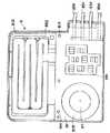
以下に、本発明の腹膜透析装置を添付図面に示す好適実施形態に基づいて詳細に説明する。先ず、図1は、本発明の腹膜透析装置を使い捨てカセット(腹膜透析用回路)8とともに示した外観斜視図であり、図2は全体構成を示した模式図である。
【0024】
両図において、腹膜透析装置1は、透析装置本体2と、この透析装置本体2に対して着脱可能に装着される腹膜透析装置用のカセット8とを備えている。
【0025】
また、図1において透析装置本体2は、カセット8を前面から装着するための二点鎖線図示の開口部21aを有したカセット装着部21と、カセット装着部21を塞ぐ状態と開く状態にするために実線と破線図示の位置に把持部22aを持って回動される蓋部材22と、表示部23と、治療の開始操作を行うための操作部(開始スイッチ)24aと、治療の停止操作を行うための操作部(停止スイッチ)24bとを有している。
【0026】
操作部24aと操作部24bとの形状および色は、それらを区別し易いように、上下に互いに異なっており、操作部24aには一つの凸部がまた操作部24bには二つの凸部が形成されている。また、誤操作防止のために、操作部24aと操作部24bは、表示部23を挟んで離間して設けられている。
【0027】
表示部23は、例えば、液晶(LCD)パネル等を備えたタッチパネルで構成されており、タッチパネルの押圧操作で透析に必要となる各種情報の表示と、装置の操作指示を音声ガイドとともに行うようにして、操作性、利便性を確保している。
【0028】
透析装置本体2は、破線図示の主基部200と、副基部201とを取付用の基部としており、図示の樹脂製のカバーをそれぞれ設けるとともに、主基部200と、副基部201とを1〜2mm厚のアルミ金属板製としさらに随所に大型孔部を穿設することで軽量化を図っている。これらの基部に軽量樹脂製のカバーが固定される。また、例えば100メガバイト以上の記憶容量を有するメモリカード204が装置の背面から破線図示のカード読取装置203に対して装填可能に設けられており、表示部23の表示内容及び音声の変更や各国別の仕様変更を迅速に行えるように構成されている。
【0029】
さらに、上記の二点鎖線図示のカセット装着部21の右側面側には遮蔽板202が破線図示の矢印方向に移動自在に設けられており、カセット8の接続チューブ85に対する機械的な干渉防止をすることでカセット8を装填位置にセットできるように構成されている。
【0030】
一方、カセット8は、透析装置本体2のカセット装着部21に対して着脱可能な形状のカセット本体81と、カセット本体81から連続形成される下本体フレーム811と、この下本体フレーム811から間隙86を介して対向して設けられた上本体フレーム812とから構成されている。
【0031】
さらに、カセット本体81には送液用のダイアフラム87と加温部83と流路切換部とが図示のように一体的に形成されており、ダイアフラム87の周囲をフランジ部材815で取り囲むように構成されている。
【0032】
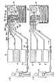
次に、図2において、腹膜透析装置1は、透析液回路ユニット3を備えており、透析液回路ユニット3は、患者Kの腹膜内(腹腔内)へ注入(注液)される透析液を収容(収納)する複数の透析液バッグ(透析液容器)4と、濃度の異なる透析液を収容する追加透析液バッグ5と、患者Kの腹膜内から排液される透析液を回収する排液タンク(排液容器)6と、患者Kの腹膜内に留置された透析カテーテル(カテーテルチューブ)7とを接続するように準備される。
【0033】
ここで、透析液回路ユニット3は、注液チューブ回路31と、追加注液チューブ回路32と、注液/排液チューブ回路33と、排液チューブ回路34とを有している。さらに、透析液回路ユニット3は、カセット8のカセット本体81に設けられた切替カセット回路82と、加温カセット回路83と、バイパス回路(患者側チューブ回路)84とを有しており、切替カセット回路82は、注液回路821と、追加注液回路822と、注液/排液回路823と、排液回路824とで構成されている。
【0034】
また、図3のカセット8の流路切換部とクランパ(クランプ)240を示した外観斜視図において、注液回路821の一端、追加注液回路822の一端、注液/排液回路823の他端、排液回路824の他端には、接続チューブ85a、85b、85c、85dが接続されている。
【0035】
そして、図2において、注液チューブ回路31の一端側は、複数の分岐チューブ回路35が分岐接続されており、各分岐チューブ回路35の一端は、透析液バッグ4に接続されており、注液チューブ回路31の他端は、注液回路821の一端に接続チューブ85aを介して接続されている。
【0036】
追加チューブ回路32の一端は、追加透析液バッグ5に接続されており、追加チューブ回路32の他端は、追加注液回路822の一端に前記接続チューブ85bを介して接続されている。
【0037】
また、注液/排液チューブ回路33の一端は、注液/排液回路823の他端に接続チューブ85cを介して接続されており、注液/排液チューブ回路33の他端は、透析カテーテル7にトランスファーチューブセット36を介して接続されている。排液チューブ回路34の一端は、排液回路824の他端に接続チューブ85dを介して接続されており、排液チューブ回路34の他端は、排液タンク6に接続されている。
【0038】
流路切換部を形成する切替カセット回路82に接続されている注液チューブ回路31、追加注液チューブ回路32、注液/排液チューブ回路33および排液チューブ回路34は、カセット8を透析装置本体2に装着したとき、透析装置本体2の前面または前方側側面に位置するようになっている。
【0039】
なお、各分岐チューブ回路35、追加注液チューブ回路32、注液/排液チューブ回路33および排液チューブ回路34には、それぞれ、流路を開閉するクレンメ(流路開閉手段)37が設けられている。
【0040】
次に、図4のカセット8の立体分解図において、本図において、既に説明済みの構成部品については同様の符号を附して説明を割愛すると、二つの分割加温カセット回路831、832の間において間隙86が形成されており、カセット本体81を透析装置本体2のカセット装着部21に装着したときに、各分割加温カセット回路831、832の両面(上面と下面)側に加温手段9のヒータ(加温部)が位置し、各分割加温カセット回路831、832が、対応するヒータにより挟まれた状態で加温されるように構成されている。
【0041】
カセット本体81には、図1に示した切替カセット回路82が設けられており、切替カセット回路82は、図3に示した注液回路821と、追加注液回路822と、注液/排液回路823と、排液回路824から構成されている。追加注液回路822の他端は、注液回路821の途中に連通しており、排液回路824の一端は、注液回路821の他端付近に連通している。
【0042】
さらに、切替カセット回路82は、カセット本体81を透析装置本体2のカセット装着部21に装着したときに、図3のクランパ240による閉塞で注液回路状態と排液回路状態との問で切り替えることができるように構成されている。
【0043】
ここで、注液回路状態とは、注液回路821(または追加注液回路822)と注液/排液回路823が連通することにより、透析液バッグ4(または追加透析液バッグ5)と透析カテーテル7が連通した状態、換言すれば患者Kの腹膜内へ透析液を注液するための状態(注液し得る状態)のことを言う。
【0044】
また、排液回路状態とは、注液/排液回路823と排液回路824が連通することにより、透析カテーテル7と排液タンク6が連通した状態、換言すれば患者Kの腹膜内から透析液を排液するための状態(排液し得る状態)のことを言う。
さらにカセット本体81には、図4に示す加温カセット回路83が設けられている。加温カセット回路83は、対向配置された二つのシート状の分割加温カセット回路831、832を備えている。
【0045】
下側の分割加温カセット回路831の一端は、注液回路821の他端に連通し、下側の分割加温カセット回路831の他端は、接続管833を介して上側の分割加温カセット回路832の一端に連通している。そして、上側の分割加温カセット回路832の他端は、注液/排液回路823の一端に連通している。
【0046】
従って、透析液は、下側の分割加温カセット回路831と、上側の分割加温カセット回路832とを、この順序で順次流れる。
【0047】
なお、本発明では、透析液は、下側の分割加温カセット回路831と、上側の分割加温カセット回路832とに分流して流れ、その後、合流するように構成してもよい。
【0048】
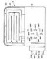
各分割加温カセット回路831、832の流路は、図5のカセット8の平面図と、図6のカセット8の背面図に示すように蛇行状をなしているが、例えば、渦巻き状をなしていてもよい。このように、蛇行状または渦巻き状とすることにより、各分割カセット回路831、832の流路が長くなり、透析液を確実に加温することができる。
【0049】
また、カセット本体81には、収縮膨張によりポンピング作動して透析液を送液するために後述するポンプ室において気密状態に保持されるダイヤフラムポンプ87が設けられており、ダイヤフラムポンプ87は、注液回路821の途中に接続されている。
【0050】
そして、フランジ部材815により、ダイヤフラムポンプ87を密閉状態で収容することで加圧するとダイヤフラムポンプ87が収縮し、減圧するとダイヤフラムポンプ87が膨張するように構成されている。
【0051】
また、カセット本体81には、前述のように、バイパス回路84が設けられている。このバイパス回路84の一端は、加温カセット回路83の上流側、本実施形態では注液回路821の途中に接続され、バイパス回路84の他端は、加温カセット回路83の下流側、本実施形態では注液/排液回路823の途中に接続されている。このバイパス回路84により、加温カセット回路83の上流側と下流側とが接続され、透析液を冷却するための循環回路が形成される。
【0052】
また、バイパス回路84に、透析液を強制冷却するために、ペルチェ素子などの強制冷却手段を設けて迅速かつ確実に冷却するようにしてもよい。
【0053】
前記切替カセット回路82、加温カセット回路83、バイパス回路84およびダイヤフラムポンプ87は、略平面的に配置されている。これにより、カセット8の厚さをより薄くすることができる。
【0054】
カセット本体81を透析装置本体2のカセット装着部21に装着したときに、加温カセット回路83の出口側(下流側)は、最終注液回路状態と、戻り回路状態との間で切替可能に構成されている。ここで、最終注液回路状態とは、加温カセット回路83の出口側が、注液/排液回路823に連通し、かつバイパス回路84に連通しない状態のことを言う。また、戻り回路状態とは、加温カセット回路83の出口側が、バイパス回路84に連通し、かつ注液/排液回路823に連通しない状態のことを言う。
【0055】
さらに、図4と図6に示すように、下本体フレーム811の、切替カセット回路82に対応する位置には、流路切換部を形成する第1〜第8支持突起881〜888が形成されている。第1支持突起881は、注液回路821の一端付近を支持するものであって、第2支持突起882は、追加注液回路822を支持するものであって、第3支持突起883は、注液回路821におけるダイヤフラムポンプ87とバイパス回路84の一端の間を支持するものであって、第4支持突起884は、注液回路821におけるダイヤフラムポンプ87と加温カセット回路83の一端の間を支持するものである。同様に、第5支持突起885は、排液回路824を支持するものであって、第6支持突起886は、注液/排液回路823における加温カセット回路83の他端とバイパス回路84の他端の問を支持するものであって、第7支持突起887は、注液/排液回路823の他端付近を支持するものであって、第8支持突起888は、バイパス回路84を支持するものである。
【0056】
切替カセット回路82と、バイパス回路84と、ダイヤフラムポンプ87とは、ブロー成形により一体的に形成されている。これにより、別部品での接合を削減することができ、カセット8の品質が向上するとともに、コストを低減することができる。
【0057】
また、加温カセット回路83の各分割加温カセット回路831および832は、それぞれ、シート成形により形成されている。これにより、各分割加温カセット回路831、832の製造が簡単になるとともに、コストを低減することができる。
【0058】
また、切替カセット回路82、バイパス回路84およびダイヤフラムポンプ87は、分割加温カセット回路831、832に高周波融着(高周波溶着)、接着により接合されている。
【0059】
ここで、分割加温カセット回路831および832をシート成形で形成するには、それぞれ、例えば、樹脂シートを2枚重ね合わせ、これらを所定のパターンで融着する。なお、融着されなかった部分が流路を形成する。
【0060】
前記切替カセット回路82、加温カセット回路83、バイパス回路84およびダイヤフラムポンプ87の構成材料としては、それぞれ、軟質の樹脂、例えば、ポリエチレン、ポリプロピレン、エチレン−プロピレン共重合体、エチレン−酢酸ビニル共重合体(EVA)等のポリオレフィン、ポリ塩化ビニル、ポリ塩化ビニリデン、ポリスチレン、ポリアミド、ポリイミド、ポリ−(4−メチルペンテンー1)、アイオノマー、アクリル系樹脂、ポリエチレンテレフタレート(PET)、ポリブチレンテレフタレート(PBT)等のポリエステル、スチレン系、ポリオレフィン系、ポリ塩化ビニル系、ポリウレタン系、ポリエステル系、ポリアミド系等の各種熱可塑性エラストマー、シリコーン樹脂、ポリウレタン等、またはこれらを主とする共重合体、ブレンド体、ポリマーアロイ等が挙げられ、これらのうちの1種または2種以上を組み合わせて(例えば2層以上の積層体として)用いることができる。
【0061】
さらに、図5において、カセット本体81には位置決め用の孔部81a、81aが形成されており、後述する位置決めピンによる位置決めを行うようにしている。さらに、上記の第1〜第8支持突起に対向して流路切換部の一部を形成する開口部81bが形成されておりクランパがこれら開口部81bに潜入することで閉塞状態にできるようにしている。
【0062】
図7のヒータ構成図に示すように、透析装置本体2内には、カセット8の加温カセット回路83を加温する加温手段9が設けられており、加温手段9は、板状(層状)の下部面ヒータ91と、板状(層状)の上部面ヒータ92と、板状(層状)の中間面ヒータ93とを有している。
【0063】
ここで、下部面ヒータ91は、下方の分割加温カセット回路831の下面を下方向から伝熱部材としてのアルミ板94aを介して加温するものであって、上部面ヒータ92は、上方の分割加温カセット回路832の上面を上方向から伝熱部材としてのアルミ板94dを介して加温するものである。そして、中間面ヒータ93は、前記間隙内86に位置して、下方の分割加温カセット回路831の上面を上方向から伝熱部材としてのアルミ板94bを介して加温するとともに、上方分割加温カセット回路832の下面を下方向から伝熱部材としてのアルミ板94cを介して加温するものである。
【0064】
これにより、下方の分割加温カセット回路831の内部の透析液は、下部面ヒータ91と中間面ヒータ93とで挟まれた状態で加温され、上方の分割加温カセット回路832の内部の透析液は、上部面ヒータ92と中間面ヒータ93とで挟まれた状態で加温される。よって、加温手段9による加温カセット回路83の内部の透析液の加温効率が向上し、透析装置本体2およびカセット8の小型化、軽量化に有利となる。
【0065】
図3に示したクランプ手段11は、カセット8の切替カセット回路82を注液回路状態と排液回路状態との一方に切り替えたり、また、加温カセット回路83の出口側を最終注液回路状態と排液回路状態との一方に切り替えたり、ダイヤフラムポンプ87のポンピング作動を補助する。
【0066】
すなわち、透析装置本体2内には、矢印で示した第1〜第8クランプ111〜118が設けられており、第1クランプ111は、第1支持突起881との協働により注液回路821の一端付近を流路が閉塞するようにクランプする。第2クランプ112は、第2支持突起882と協働して追加注液回路822を流路が閉塞するようにクランプする。第3クランプ113は、第3支持突起883と協働して注液回路821におけるダイヤフラムポンプ87とバイパス回路84の一端の問を流路が閉塞するようにクランプする。第4クランプ(ポンピング制御用クランプ)114は、第4支持突起884と協働して注液回路821におけるダイヤフラムポンプ87と加温カセット回路83の一端の問を流路が閉塞するようにクランプする。
【0067】
同様に、第5クランプ115は、第5支持突起885と協働して排液回路824を流路が閉塞するようにクランプする。第6クランプ116は、第6支持突起886と協働して注液/排液回路823における加温カセット回路83の他端とバイパス回路84の他端の間を流路が閉塞するようにクランプする。第7クランプ117は、第7支持突起887と協働して注液/排液回路823の他端付近を流路が閉塞するようにクランプする。そして、第8クランプ118は、第8支持突起888と協働してバイパス回路84を流路が閉塞するようにクランプする。
したがって、切替カセット回路82を注液回路状態に切り替えるときには、第1クランプ111(あるいは第2クランプ112)、第4クランプ(ポンピング制御用クランプ)114、第6クランプ116、第7クランプ117を、それぞれ、アンクランプ状態に切り替えるとともに、第2クランプ112(あるいは第1クランプ111)、第5クランプ115、第8クランプ118を、それぞれ、クランプ状態に切り替える。そして、ポンピング作動手段10によりチャンバー814内を加圧するときに時、第4クランプ114をアンクランプ状態に切り替えるとともに、第3クランプ113をクランプ状態に切り替える。さらに、ポンピング作動手段10によりチャンバー814内を減圧するときには、第4クランプ114をクランプ状態に切り替えるとともに、第3クランプ113をアンクランプ状態に切り替える。これにより、透析液バッグ4(あるいは追加透析液バッグ5)から透析カテーテル7に向かって透析液を送液、すなわち、注液することができることから、図8(a)に図示の透析液の腹腔内への送液状態にすることができる。
【0068】
また、切替カセット回路82を排液回路状態に切り、替えるときには、第7クランプ117、第8クランプ118を、それぞれ、アンクランプ状態に切り替えるとともに、第1クランプ111、第2クランプ112、第4クランプ114、第6クランプ116を、それぞれ、クランプ状態に切り替えることで図8(b)に図示の排液の回収状態にすることができる。
【0069】
また、ポンピング作動手段でポンプ室内を減圧するときには、第3クランプ113をアンクランプ状態に切り替えるとともに、第5クランプ115をクランプ状態に切り替える。さらに、ポンピング作動手段によりチャンバー814内を加圧するときには、第3クランプ113をクランプ状態に切り替えるとともに、第5クランプ115をアンクランプ状態に切り替えることにより、透析カテーテル7から排液タンク6に向かって透析液を排液することができる。
【0070】
ダイヤフラムポンプ87と、第3クランプ113と、第4クランプ114と、第5クランプ115、ポンピング作動手段とで、透析液を送液する送液手段が構成される。
【0071】
さらに、切替カセット回路82が注液回路状態にあって、加温カセット回路83の出口側が最終注液回路状態にあるときには、第7クランプ117がアンクランプ状態で、第8クランプ118がクランプ状態となっている。
【0072】
加温カセット回路83の出口側を戻り回路状態に切り替えるときには、第1クランプ111、第2クランプ112、第7クランプ117をクランプ状態に切り替えるとともに、第8クランプ118をアンクランプ状態に切り替える。これにより、透析液は、加温カセット回路83の出口側から透析カテーテル7に向かって流れることなく、バイパス回路84内をダイヤフラムポンプ87に向かって流れる。すなわち、透析液は、バイパス回路87と加温カセット回路83との間を循環する。
【0073】
第7クランプ117と第8クランプ118とで、加温カセット回路83の出口側を最終注液回路状態と戻り回路状態に切り替える注液戻り回路切替手段が構成される。
【0074】
ここで、透析液を排液するときは、その排液は、バイパス回路84を経由して、排液タンク6に回収される。これにより、流路の構成を簡素化することができる。
【0075】
以上のように、カセット本体81に、切替カセット回路82と、加温カセット回路83と、バイパス回路84と、ダイヤフラムポンプ87とを設けることにより、腹膜透析装置1の小型化および軽量化を図ることができ、腹膜透析装置1の運搬等の取り扱いが容易になり、円滑な医療行為を行うことができる。
【0076】
特に、各分割加温カセット回路831、832を流れる透析液が、それぞれ、対応するヒータで挟まれた状態で加温されるので、透析液の加温効率が向上し、これにより、腹膜透析装置1をさらに小型、軽量にすることができる。
【0077】
一方、図2に示すように、腹膜透析装置1は、透析液の温度管理等のために、種々のセンサを備えている。
【0078】
すなわち、透析装置本体2の、加温カセット回路83の下流側には、加温カセット回路83の出口側(下流側)を流れる透析液の温度(出口液温)を測温(検出)する出口液温用温度センサ12Aが設置され、加温カセット回路83の上流側には、加温カセット回路83の入口側(上流側)を流れる透析液の温度(入口液温)を測温(検出)する入口液温用温度センサ12Bが設置されている。
【0079】
ここで、出口液温用温度センサ12Aおよび入口液温用温度センサ12Bとしては、それぞれ、応答速度が極めて速いサーモパイル型赤外線センサ(非接触型の温度センサ)を用いるのが好ましい。これにより、各面ヒータ91、92、93の温度を高精度に制御することができる。
【0080】
また、図7に示すように各面ヒータ91、92、93には、それぞれ、その温度を測温(検出)するためのサーミスタなどのヒータ用温度センサ13が設けられている。さらに、透析装置本体2には、切替カセット回路82の入口側および出口側の気泡を検知する気泡センサ14がそれぞれ設けられている。なお、腹膜透過装置1は、回路の閉塞を検出する閉塞センサ、その他、種々のセンサ(各種センサ16)を備えている。
【0081】
さらに、図9のブロック図に示すように、腹膜透析装置1は、透析液の注液、排液等の各制御を行う制御システム(制御手段)15を備えている。
【0082】
すなわち、制御システム15は、CPU151と、記憶部152とを備えており、CPU151には、複数のクランプ111〜118を制御するクランプ制御ブ153、複数の面ヒータ91、92、93の温度を制御するヒータ制御部154、ポンピング作動手段10を制御するポンピング作動制御部155が、それぞれ、電気的に接続されている。また、CPU151には、それぞれ、出口液温用温度センサ12A、入口液温用温度センサ12B、各ヒータ用温度センサ13、各気泡センサ14、表示部23、操作部24a、24bが、それぞれ、電気的に接続されている。なお、CPU151には、電源回路156、バッテリー回路157と音声発生回路400とカセット装填手段300を制御するカセット装填制御部301とが電気的に接続されている。また、表示部23には上記のメモリカードを装填可能にしたカード読取装置203が電気的に接続されている。
【0083】
この制御システム15は、出口液温用温度センサ12Aにより測温された温度が予め設定された所定の温度(本実施形態においては39℃)以上になると、クランプ制御部153により、第7クランプ117を制御してクランプ状態に切り替え、第8クランプ118を制御してアンクランプ状態に切り替えるとともに、ヒータ制御部154により、複数の面ヒータ91、92、93の駆動を停止させるオフ状態に切り替える。
【0084】
また、各面ヒータ91、92、93の出力(出力値)は、透析液の温度制御フロー、透析液の温度に基づいて選択される。すなわち、制御システム15は、出口液温用温度センサ12Aにより側温された温度と、入口液温用温度センサ12Bにより測温された温度とに基づいて、注液される透析液の温度が所定の温度範囲内になるように複数の面ヒータ91、92、93の出力(駆動)を制御する。
そして、クランプ制御部153により、第1クランプ111(あるいは第2クランプ112)、第4クランプ114、第6クランプ116、第7クランプ117を制御してアンクランプ状態に切り替えるとともに、第2クランプ112(あるいは第1クランプ111)、第5クランプ115、第8クランプ118を制御してクランプ状態に切り替える。これにより、切替カセット回路82を注液回路状態に切り替えることができる。また、ヒータ制御部154により、複数の面ヒータ91、92、93に電力(出力)を供給するように制御する。これにより、加温カセット回路83を流れる透析液を加温する加温工程、換言すれば、透析液の温度制御フローが予熱工程に入る。
【0085】
複数の面ヒータ91、92、93に電力の供給を開始してからT1時間経過すると、予熱工程が終了する。この予熱工程が終了すると、ポンピング作動制御部155により、ポンピング作動手段10を制御してポンプ室内の加圧、減圧を交互に繰り返す。また、クランプ制御部153により、第4クランプ114を制御してクランプ状態、アンクランプ状態の切り替えをチャンバー814内の加圧、減圧に合わせて交互に繰り返すとともに、第3クランプ113を制御してクランプ状態、アンクランプ状態の切り替えをチャンバー814内の加圧、減圧に合わせて交互に繰り返す。これにより、ダイヤフラムポンプ87をポンピング作動(収縮、膨張)させて、透析液バッグ4から透析カテーテル7に向かって透析液を送液し、注液する。
【0086】
また、前記予熱工程が終了すると、透析液の温度制御フローが初期加温工程に入る。初期加温工程が終了すると、透析液の温度制御フローは通常加温工程に入る。通常加温工程においては、複数の面ヒータ91、92、93の出力制御は、出口液温用温度センサ12Aにより測温された温度が33℃未満の場合には、P制御によるヒータの出力値を複数の面ヒータ91、92、93に出力する。
【0087】
一方、出口液温用温度センサ12Aにより測温された温度が33℃以上39℃未満の場合には、PI制御によるヒータの出力値を複数の面ヒータ91、92、93に出力する。
【0088】
これにより、複数の面ヒータ91、92、93の出力制御を高精度に行うことできる。初期加温工程、または通常加温工程において、出口液温用温度センサ12Aにより測温される温度が39℃以上になると、クランプ制御部153により、第7クランプ117を制御してクランプ状態に切り替えるとともに、第8クランプ118を制御してアンクランプ状態に切り替える。また、ヒータ制御部154により、複数の面ヒータ91、92、93への電力の供給を停止、換言すれば複数の面ヒータ91、92、93をオフに切り替える。これにより、加温カセット回路83の出口側を戻り回路状態に切り替えることができ、透析液は、加温カセット回路83から、透析カテーテル7へ向かって流れることなく、バイパス回路84へ向かって流れ、そのバイパス回路84を介して加温カセット回路83の上流側に戻り、バイパス回路84および加温カセット回路83の間を循環し、その間に温度が下がる(冷却される)。すなわち、透析液の加温制御フローは冷却工程に移行する(ステップ12)。したがって、患者Kの体温よりもかなり高温(39℃以上の温度)の透析液が患者Kに注液されることがなく、安全な透析治療を行うことができる。
【0089】
そして、出口液温用温度センサ12Aにより測温される温度が39℃未満になると、クランプ制御部153により、第7クランプ117を制御してアンクランプ状態に切り替えるとともに、第8クランプ118を制御してクランプ状態に切り替える。さらに、複数の面ヒータ91、92、93をONに切り替える。これにより、加温カセット回路83の出口側を最終注液回路状態に復帰することでき、再び初期加温工程または通常加温工程へ移行する。患者Kの腹膜内に所定量の透析液を注液(注入)すると、透析液の注液は終了する。
【0090】
この透析液の注入が終了した後に、クランプ制御部154により、第7クランプ117、第8クランプ118を制御してアンクランプ状態に切り替えるとともに、第4クランプ114、第6クランプ116を制御してクランプ状態に切り替える。これにより、切替カセット回路82を排液回路状態に切り替えることができる。
【0091】
そして、ポンピング作動制御部155により、ポンピング作動手段10を制御してチャンバー814の減圧、加圧を交互に繰り返す。また、クランプ制御部により、第3クランプ113を制御してアンクランプ状態、クランプ状態の切り替えをチャンバ内−814の減圧、加圧に合わせて交互に繰り返すとともに、第5クランプ115を制御してクランプ状態、アンクランプ状態の切り替えをチャンバー814内の減圧、加圧に合わせて交互に繰り返す。これにより、ダイヤフラムポンプ87をポンピング作動させて、透析カテーテル7から排液タンク6に向かって腹膜内の透析液を送液し、排液することができる。
【0092】
続いて、図10は透析装置本体2の蓋部材22以外のカバーを全て外して示した外観斜視図であって、蓋部材22を開くことでカセット装着部21の開口部が見える状態にした図である。
【0093】
本図において、既に説明済みの構成部品については同様の符号を附して説明を割愛すると、主基部200と副基部201とは一点鎖線で示される分離面Hから上下に着脱可能に個別に構成されており、不図示の複数のネジを用いて図示のように一体的に固定されることで、上記のカセット装填部21を形成する一方で、ネジを外すことで簡単に上下に分離できるように構成されている。
【0094】
また、蓋部材22は、主基部200において回動軸支された軸体219に固定された左右の軸支部材209で回動自在に軸支される孔部を形成した左右の軸支部材206を固定しており、図示のように手前側に開いた状態にされる。さらに、副基部201において軸体219により同時に回動するように回動自在に設けられた左右の係止部材209により左右のピン208が係止状態にされることで閉じた位置に維持される。そして、蓋部材22が閉じた状態を主基部200に固定されたドアセンサ210で検出して、蓋部材22が図示の開いた状態では動作しないようにしている。
【0095】
図11(a)から(c)は、蓋部材22の動作説明図であって、図10のX-X線矢視断面図に相当する図である、本図において主基部200に固定された左右の軸支部材207の軸体により回動自在に蓋部材22が回動自在に設けられており、図11(a)に図示のようにピン208が係止部材209により係止されることで閉じた位置に維持される。係止部材209は、軸体219を回動軸として回動自在に設けられる一方で、圧縮バネ220を他端に設けており、図示の係止状態を維持する。図11(b)において、蓋部材22が手前側に開かれると圧縮バネ220が圧縮されて、ピン208の上を係止部材209の爪部が図示のように乗り上げて、係止状態が解除されて手前がわに開き、図10に図示の状態となる。
【0096】
また、図11(c)に図示のように蓋部材22を手動で矢印方向に移動するとピン208が係止部材209の傾斜面209bに当接し、さらに移動することでピン208が係止部材209の爪部に乗り上げることで、図11(a)に図示の状態となり、ドアセンサ210で蓋部材22が閉じたことを検出する。
【0097】
以上のように蓋部材22を構成することで、カセットが装填された状態で、蓋部材22が閉じた状態以外での一切の動作を停止させて、異物の混入を防止して予想外の事故防止を図るようにしている。
【0098】
再度、図10において、カセット装填部21にはアルミ板製の昇降部材222が設けられており、この昇降部材222の角部において、左右のカセット係止爪部材211が破線図示の軸体223により一体的に固定されており、さらに昇降部材222に対して軸体223が回動自在に設けられている。また、左側のカセット係止爪部材211の下方には押圧することで左右のカセット係止爪部材211を同時に解除位置に駆動するカセットボタン212が設けられている。
【0099】
図12は、昇降部材222に設けられる、左右のカセット係止爪部材211の立体分解図であって、図示のように左右のカセット係止爪部材211は軸体223に一体的に固定されており、矢印方向に回動自在になるように昇降部材222に設けられている。また、カセットボタン212には圧縮コイルバネ224が挿通されてセットされており、左右のカセット係止爪部材211を常時係止位置に移動付勢している。
【0100】
再度、図10において、副基部201上には、上記のクランプ手段11を構成する3本のカム軸体256と、これらのカム軸体256を個別駆動するステッピングモータ253、254、255とが図示の位置に固定されている。また、切替弁106と、真空ポンプ250と空気圧発生装置104と真空圧発生装置105であるリザーブタンクが図示の位置に設けられている。
【0101】
さらに副基部201の上面を跨ぐようにして取付部材216が固定されており、この取付部材216により上下の制御基板214、215を図示のように支持及び固定している。
【0102】
続いて、図13は図10で説明した分離面Hから主基部200と副基部201とを分離し、副基部201を反転させた様子を示した外観斜視図である。本図において、既に説明済みの構成部品については同様の符号を附して説明を割愛すると、主基部200に設けられた昇降部材222を昇降駆動するためのステッピングモータである昇降モータ251が図示の位置に固定されている。また、昇降部材222の奥側には上記の下部面ヒータ91と中間ヒータ93が設けられている。また、この中間ヒータ93の上方にはレバー軸体227を回動中心にして両矢印方向に回動されるとともに、不図示のトーションバネによる付勢力で図示の位置に移動するカセット排出レバー228が設けられている。このカセット排出レバー228には、さらにカセット有無センサ226の光軸を遮ることでセンサ226をオンするアクチエータ部228aが先端に形成されている。
【0103】
以上の構成により、図14(a)〜(c)の操作説明図において、一点鎖線図示のカセット8が矢印方向に装填されて昇降部材222の上にセットされるときに、カセット前端面8cが上記の左右のカセット係止爪部材211に当接して、矢印方向に退避して挿入を可能にする。さらに、カセット8を挿入するとカセットの間隙86が中間ヒータ93の中に入りこみ、さらに押し込むことで図14(b)に図示のようにカセット前端面8bが上記のカセット排出レバー228に対して当接されて移動されてセンサをオンするとともに、カセットの排出のための力を蓄える状態になる。これに前後して左右のカセット係止爪部材211が図示の位置に復帰することでカセット後端面8aに対する係止状態とする。以上で、カセット8の昇降部材222上への装填を終える。
【0104】
そして、透析の終了後にカセット8を取り出すときには、カセットボタン212を押圧することで、左右のカセット係止爪部材211が下方に移動されてカセット後端面8aに対する係止状態が解除されるとともに、カセット排出レバー228に蓄積された排出力の作用で外部にカセット8が排出される。
【0105】
以上のように昇降部材222が下方位置にあるときにカセットを装填及び排出することが可能となる。
【0106】
再度、図13において、副基部201には上部面ヒータ92と、樹脂製の4本のスタッド231と2本のステンレス製の位置決めピン230と、周囲にOリング236を設けたポンプ室235と、8個のクランパ240と、チューブ挟持部233とが配設されている。
【0107】
そして、図15の図10のX-X線矢視断面図において、各スタッド231は昇降部材222が上方に移動されることで第2のカム部材248に当接する端面231aを設けている。
【0108】
昇降部材222の4隅にはカムローラ軸体245で回動軸支されるカムローラ246が設けられており、これらのカムローラ246を主基部200で軸支されたカム軸体244に固定された第1のカム部材243のカム面で夫々支持している。第1のカム部材243は図示のように左右一対分と図示しない反対面側とに設けられおり、一方の第1のカム部材243のみをモータ251で駆動することで他方の第1のカム部材243の駆動を同期して行えるように構成されている。
このために、各第1のカム部材243の側面には軸支部243a、243bが設けられており、これらに図16の側面図に示すようなリンク部材242を回動自在に連結している。これらのリンク部材242は図示のように主基部200に穿設された孔部200aから第1のカム部材243に固定される。
【0109】
一方、昇降部材222の両側の側面には軸体247が固定されており、この軸体247により回動自在に軸支された第2のカム部材248が4個分設けられており、この第2のカム部材248の軸支部249において上記の下部面ヒータ91のアルミ板を支持した所謂平行リンク機構を構成している。
【0110】
また、中間ヒータ93については、昇降部材222に対して片支持状態で固定されている。さらに、位置決めピン230はカセット8が二点鎖線図示の位置に挿入された時点では、孔部8aに挿入しておらず、カセット8が破線図示の位置に移動したときに図示のように入ることでカセットを不動状態に維持する。また、カセット8が破線図示の位置に移動したときに、ポンプ室235が上記のダイアフラム87を気密状態に維持する状態になる。
【0111】
また、遮蔽板202は、図16に図示のように主基部200に固定された2本のフラットネジ237により溝部238aが案内されるガイド部材238を延設しており、引っ張りバネ239による引っ張り力によりカセットなしの状態で図示の位置に移動するとともに、カセット8が挿入されると端部202aが接続チューブに当接することで矢印方向に移動する。
【0112】
以上の構成により、図17(a)、(b)の昇降部材222の動作説明図において、昇降部材222は下方位置に移動しており、二点鎖線図示のカセット8が図示のようにセットされることで、中間ヒータ93が間隙部に入る。
【0113】
これに続き、モータが起動されることで第1のカム部材243が矢印方向に回動されて、図17(b)に図示のように第1のカム部材243のカム面上のカムローラ246が上方移動して、上部面ヒータ92とポンプ室235との当接状態にされる。一方、これに前後して下部面ヒータ91は、第2のカム部材がスタッド231に当接することで回動される結果、第2のカム部材248の軸支部249を上方に移動して下部面ヒータ91を図示の位置に移動する。
【0114】
以上で、各ヒータが分割加温カセット回路831、832に対する当接状態に維持される。カセット取り出しのときには、逆方向に移動して図17(a)に示した状態になる。
【0115】
図17(b)に図示の状態では、図18のチューブ挟持手段233の外観斜視図に示したように接続チューブ85が破線図示の気泡センサ14を内蔵した挟持部材263間に挟持される状態となることで、気泡検出を確実に行う。
【0116】
このとき、図示のように2本の圧縮バネ261を設けて副基部201において上下移動可能に設けられた押圧部材260が移動して、接続チューブ85が挟持部材263間に挟持される状態となるが、圧縮バネ261は圧縮された状態となっているので、カセット8が図17(a)に示した位置に移動すると、圧縮バネ261が元の状態に戻ろうとする力により押圧部材260が移動される結果、接続チューブ85の挟持状態が解除される。
【0117】
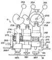
次に、図19はクランプ手段11の正面図である。本図において、既に説明済みの構成部品については同様の符号を附して説明を割愛すると、カセット8のバイパス回路84を閉塞するクランパ240は、上記の各モータ253、254、255により個別駆動されるカム部材257のカム面に当接するカムフォロアローラ258を設けたカム組立体259の端部に固定されている。
【0118】
また、各カム組立体259は、副基部201に固定されたクランパベース266に穿設された孔部266aに対して中心部材274が挿通され、キャップ部材273の内部において復帰用の大径コイルバネ275を設けた状態で完成されることで、カムフォロアローラ258がカム部材257のカム面に対して当接するようにして完成される。
【0119】
図20は、各カム組立体259の立体分解図である、本図において上記の中心部材274には破線図示の有底穴部274bが形成されており、この有底孔部27bの底面には雌ネジ孔部274aが設けられている。一方、上記のキャップ部材273には矩形孔部273aが穿設されており、中心部材274の形状部274dをこの矩形孔部273aに挿通した後に、カムフォロアローラ258を軸支した軸支部材270を形状部274dに被せた後に、ネジ271で形状部274の雌ネジ部274cに螺合結合する。
【0120】
一方、中心部材274の有底穴部274b内には小径コイルバネ276がセットされた後に、蓋部材277が挿入され、長ネジ278を上記の雌ネジ孔部274aに螺合させることで、蓋部材277が小径コイルバネ276を介在した状態で固定される。そして、最後にクランパ240に穿設された孔部240aに各ネジ279を通過させて、蓋部材277の雌ネジ部277aに螺合して完成する。
以上の構成により、図19において、通常はカム面に倣うようにして各カム組立体259が上下に駆動され、過剰な負荷が加わると小径コイルバネ276が圧縮されることで、流路が過剰に閉塞されることを防止できる。
【0121】
図21は、透析装置本体2の副基部201に設けられるダイヤフラムポンプ87をボンピング作動させるために上記のポンプ室235に接続されるポンピング作動手段10の配管図である。
【0122】
本図において、透析装置本体2内には、エア回路(エア加減圧回路)101が設けられており、カセット本体81をカセット装着部21に装着したときに、エア回路101の一端がポンプ室235に連通するように構成されている。このポンプ室235には液漏れ検出機能を有するセンサブロック280と大気開放用バルブ281を中継して、切替弁106で切り替えられる一対の分岐エア回路102、103が分岐接続されている。分岐エア回路102の他端部には、圧力センサ282を接続した空気圧発生装置104が接続されており、他方の分岐エア回路103には、圧力センサ282を接続した真空圧発生装置(減圧装置)105が接続されている。
【0123】
分岐エア回路102、103の開放端には、真空ポンプ250の吸気側と排気側とサイレンサ284に切り替えるバルブ285、286が接続されている。
【0124】
以上の構成により、切替弁106により、エア回路101と一方の分岐エア回路102とが連通した加圧状態と、エア回路101と他方の分岐エア回路103とが連通した減圧状態との間で切替を行うことで、ポンプ室235内部を加圧減圧状態に変化させることでベローズ87による送液を行う。すなわち、ポンピング作動手段でポンプ室235内を減圧するときには、図3に示した第3クランプ113をアンクランプ状態に切り替えるとともに、第5クランプ115をクランプ状態に切り替える。さらに、ポンピング作動手段によりポンプ室235内を加圧するときには、第3クランプ113をクランプ状態に切り替えるとともに、第5クランプ115をアンクランプ状態に切り替えることにより、透析カテーテル7から排液タンク6に向かって透析液を排液することができる。
【0125】
また、送液量は、上記の圧力センサ282、283による圧力変化から測定できる。
【0126】
尚、本発明は上記説明の構成に限定されず、例えば、カセットの加温回路を1系統にした場合において、上下からヒータで加温するように構成した場合にも適用可能であることは言うまでもない。
【0127】
さらに、上記のように自宅治療のために小型軽量化の実現のために腐心しており、各部品にアルミ材料、軽量樹脂材料をしたが、例えば病院内における設置タイプとして利用する場合には設計上の自由度が高まることになる。
【0128】
【発明の効果】
以上説明したように、本発明の腹膜透析装置によれば、ダイアフラム、加温部が一体的に形成された使い捨てカセットを用いた腹膜透析装置において、流路切換え動作が静かで、かつ加温能力が高く、小型軽量に構成できる腹膜透析装置を提供できる。
【0129】
加えて、着脱自在のカセットの装填作業を誰でも確実かつ簡単に行うことができ、しかも加温能力を十分に確保した腹膜透析装置を提供できる。
【図面の簡単な説明】
【図1】本発明の腹膜透析装置をカセット8とともに示した外観斜視図である。
【図2】本発明の腹膜透析装置の実施形態を模式的に示す図である。
【図3】カセット8の流路切換部とクランパ240を示した外観斜視図である。
【図4】カセット8の立体分解図である。
【図5】カセット8の平面図である。
【図6】カセット8の背面図である。
【図7】カセット8の加温回路とヒータの関係図である。
【図8】(a)は透析液の腹腔内への送液状態にする模式図、(b)は排液を送液状態にする模式図である。
【図9】透析装置本体のブロック図である。
【図10】透析装置本体のカバーを外した外観斜視図である。
【図11】 (a)から(c)は、蓋部材22の動作説明図であって、図10のX-X線矢視断面図に相当する図である。
【図12】昇降部材222に設けられる、左右のカセット係止爪部材211の立体分解図である。
【図13】図10で説明した分離面Hから主基部200と副基部201とを分離し、副基部201を反転させた様子を示した外観斜視図である。
【図14】 (a)〜(c)は、カセット8の係止機構の動作説明図である。
【図15】図10のX-X線矢視断面図である。
【図16】透析装置本体の右側面図である。
【図17】 (a)〜(b)は、カセット装填手段の動作説明図である。
【図18】チューブ挟持手段233の外観斜視図である。
【図19】クランブ手段11の正面図である。
【図20】クランブ組立体259の立体分解図である。
【図21】ダイヤフラムポンプ87をボンピング作動させるためのポンピング作動手段10の配管図である。
【符号の説明】
1 腹膜透析装置
2 透析装置本体
21 カセット装着部
22 蓋部材
23 表示部
24a、24b 操作部
3 透析液ユニット
31 注液チューブ回路
32 追加注液チューブ回路
33 注液/排液チューブ回路
34 排液チューブ回路
35 分岐チューブ回路
36 トランスファーチューブセット
37 クレンメ
4 透析液バッグ
5 追加透析液バッグ
6 排液タンク
7 透析カテーテル
8 カセット
81 カセット本体
811 下本体フレーム
812 上本体フレーム
82 切替カセット回路
821 注液回路
822 追加注液回路
823 注液/排液回路
824 排液回路
83 加温カセット回路
831 分割加温カセット回路
832 分割加温カセット回路
833 接続管
84 バイパス回路
85a〜85d 接続チューブ
86 間隙
87 ダイヤフラムポンプ
881 第1支持突起
882 第2支持突起
883 第3支持突起
884 第4支持突起
885 第5支持突起
886 第6支持突起
887 第7支持突起
888 第8支持突起
9 加温手段
91 下部面ヒータ
92 上部面ヒータ
93 中間ヒータ
94a〜94d アルミ板
10 ポンピング作動手段
101 エア回路
102 分岐エア回路
103 分岐エア回路
104 空気圧発生装置
105 真空圧発生装置
106 切替弁
11クランプ手段
111 第1クランプ
112 第2クランプ
113 第3クランプ
114 第4クランプ
115 第5クランプ
116 第6クランプ
117 第7クランプ
118 第8クランプ
12A 出口液温用温度センサ
12B 入口液温用温度センサ
13 ヒータ用温度センサ
14 気泡センサ
15 制御システム
151 CPU
152 記憶部
153 クランプ制御部
154 ヒータ制御部
155 ポンピング作動制御部
156 電源回路
157 バッテリー回路
16 各種センサ
S1〜S12 ステップ
200 主基部
201 副基部
202 遮蔽板
203 カード読取装置
204 メモリカード
222 昇降部材
228 カセット排出レバー
233 チューブ挟持手段
235 ポンプ室
240 クランパ[0001]
BACKGROUND OF THE INVENTION
The present invention relates to a peritoneal dialysis apparatus using a disposable cassette (circuit for peritoneal dialysis) in which a diaphragm and a heating part are integrally formed.
[0002]
[Prior art]
In recent years, dialysis methods using peritoneal dialysis have attracted attention for reasons such as lower treatment costs and prevention of peritoneal adhesion compared to dialysis methods using an artificial kidney.
[0003]
In general, a peritoneal dialysis apparatus used in a dialysis method by peritoneal dialysis is provided in a dialysis fluid container (bag) containing a peritoneal dialysis fluid (hereinafter referred to as dialysis fluid) injected into a patient's peritoneum (intraperitoneal). A connected injection bag and a reservoir bag connected to a drainage container (bag) for collecting dialysate discharged from the patient are placed in a pressure chamber and used. That is, a pressure chamber for accommodating an injection bag and a reservoir bag is formed in the dialysis device body of the peritoneal dialysis device, and the injection bag or the reservoir bag is pumped by pressurizing and depressurizing the inside of the chamber. It is. The dialysis machine body is provided with a heater for heating the dialysis solution in the injection bag to a predetermined temperature range.
[0004]
However, in the conventional peritoneal dialysis device, the chamber and the heater need to be sized corresponding to the infusion bag and the reservoir bag, and the peritoneal dialysis device itself is increased in size and the peritoneal dialysis device is heavy. Become. Therefore, in the medical field, especially home medical care, a large installation space is required for the peritoneal dialysis device, and handling of the peritoneal dialysis device becomes troublesome and hinders smooth medical practice. There is a fear.
[0005]
On the other hand, Japanese Patent No. 313887 proposes a peritoneal dialysis apparatus in which a valve actuator is opened and closed so that the flow path of the disposable cassette is switched when selected. JP-A-11-347115 proposes a disposable cassette in which a pump part (diaphragm) for feeding peritoneal dialysate and a heating part are integrally formed. This cassette is heated from both sides, and is configured such that the heated peritoneal dialysis fluid is sent into the abdominal cavity of the patient by two pump parts (diaphragms).
[0006]
However, according to the former, since the valve actuator is operated intermittently, there is a problem that the operation sound of the valve is generated during dialysis during sleep at night, which is harsh.
[0007]
Moreover, according to the latter, there existed a problem that heating capability was not enough with respect to the liquid feeding capability of a pump.
[0008]
Therefore, the present invention has been made in view of the above problems, and in the peritoneal dialysis apparatus using the disposable cassette in which the diaphragm and the heating unit are integrally formed, the flow path switching operation is quiet, and It is intended to provide a peritoneal dialysis device that has a high heating capability and can be configured to be small and light.
[0009]
In addition, it is an object of the present invention to provide a peritoneal dialysis apparatus in which anyone can reliably and easily load a detachable cassette and has sufficient heating capability.
[0010]
[Means for Solving the Problems]
In order to solve the above-mentioned problems and achieve the object, the present inventionThe peritoneal dialysis apparatus according to the present invention has the following configuration. That is,
A dialysis solution that stores a dialysate by loading a disposable cassette that integrally forms a heating unit and a channel switching unit formed as two upper and lower channels through a diaphragm and a gap A peritoneal dialysis device used in connection with a liquid container and a drainage container,
A main body provided with an operation unit and a display unit;
Cassette loading means for detachably loading the cassette;
After loading the cassette, a pumping operation means for feeding the liquid from the dialysate container and the liquid to the drainage container by bringing the diaphragm into a positive pressure state and a negative pressure state;
Heater means provided with a three-layer surface heater of an upper surface heater, an intermediate surface heater, and a lower surface heater in order to heat a predetermined amount of dialysate to a predetermined temperature in the heating unit after loading the cassette When,
In order to form a flow path for feeding the heated dialysate into the abdominal cavity of the patient almost continuously and aspirating and draining the dialysate from the abdominal cavity after a predetermined time has elapsed, Channel switching means for opening and closing;
Control means connected to the operation section, the display section, the cassette loading means, the pumping operation means, the heater means, and the flow path switching means,
The cassette includes an upper divided heating cassette circuit and a lower divided heating cassette circuit,
The intermediate surface heater is disposed in a gap between the divided heating cassette circuit of the information and the divided heating cassette circuit below.
The dialysate inside the lower divided heating cassette circuit is heated in a state sandwiched between the lower surface heater and the intermediate surface heater, and the dialysate inside the upper divided heating cassette circuit is Heating is performed between the upper surface heater and the intermediate surface heater..
[0012]
In addition, the flow path switching unit is configured to open and close the flow path switching unit by rotating a plurality of cam shafts including a plurality of cams continuously or intermittently by a drive unit of each cam shaft. It is characterized by providing a clamper (clamp).
[0013]
Further, the clamper of the flow path switching means includes a return large-diameter coil spring for contact with the cam surface of the cam, and a small-diameter coil spring for preventing excessive blockage of the flow path of the flow path switching unit, It is characterized by having.
[0014]
The cassette loading means includes a cassette lifting / lowering means for lifting / lowering the cassette after the cassette is inserted from the opening on the front surface of the main body, and the cassette lifting / lowering means moves the cassette from a lower position to an operating position. The three-layer surface heaterThe upper divided heating cassette circuit is in close contact between the upper surface heater and the intermediate surface heater, and the lower divided heating cassette circuit is in close contact between the lower surface heater and the intermediate surface heater. The cassetteIn addition to being positioned at a predetermined position, the pump chamber of the pumping operation means is maintained in an airtight state with respect to the diaphragm, and is configured to be opened and closed by the clamper of the flow path switching means.
[0015]
The main body has a main base for installation and a sub-base fixed to the main base as an attachment base.,The cassette lifting means is lifted and lowered by a first cam mechanism that is provided on the main base and is driven by a motor.surfaceA lifting member that fixes the heater in a single-supported state, and the lower surface heater that is lifted and lowered by a second cam mechanism provided on the lifting member, wherein the second cam mechanism is planted downward from the sub-base. It is characterized by being configured to be rotationally driven in contact with a stud provided.
[0016]
Further, the cassette is moved up to the operating position by the cassette raising / lowering means, and a pin for entering and positioning in the positioning hole portion of the cassette is implanted in the sub-base portion.
[0017]
Also, the aboveFront of the main unitAn openable / closable lid that closes the opening of the main body is disposed on the front surface of the main body, and the cassette has a connection tube connected to the dialysate container and the drainage container on the side surface, and the cassette Is provided with a shielding plate that is moved to prevent interference with the connection tube when loaded through the opening.
[0018]
Also,A sandwiching means for sandwiching the connection tube in a state in which the cassette is loaded through the opening, and a bubble that is disposed in the sandwiching means and detects bubbles inside the connection tube sandwiched by the sandwiching means And further comprising a sensor.is doing.
[0019]
The main base and the sub base are made of aluminum plate to reduce the weight, and the cassette lifting / lowering means is disposed in the main base, and the control base of the control means and a battery are included in the sub base. A power source means; the pump chamber of the pumping operation means; a vacuum pump; a tank; and the flow path switching means.Drive part of each camshaftAnd is arranged.
[0020]
The cassette loading means is configured to insert a cassette from the opening on the front surface of the main body and set it on the cassette lifting / lowering means.TheLockingAnd the cassette is locked,When ejecting the cassetteLocking means for releasing the lock state and the cassette front end surfaceButRotates against the urging force by contactingShiDetects the presence of cassettesDoLever means for turning on / off the sensor means, the presence / absence detection of the cassette by cooperation of the lever means and the locking means, and the cassetteofDischargeWhenIt is characterized by performing.
[0021]
Further, the pumping operation means communicates with the pump chamber to thereby provide the diaphragm.ofPositive pressureStatusAnd negative pressure stateAndSwitching valve and vacuum pump,A positive pressure and a negative pressure reserve tank, and a pressure sensor for detecting the pressure in each reserve tank.Preparation, Dialysate supply volume can be monitored by the pressure sensorIsIt is characterized by that.
[0022]
The storage card for changing the screen of the display unit is detachable from the back surface of the main body.
[0023]
DETAILED DESCRIPTION OF THE INVENTION
Below, the peritoneal dialysis apparatus of this invention is demonstrated in detail based on suitable embodiment shown to an accompanying drawing. First, FIG. 1 is an external perspective view showing the peritoneal dialysis apparatus of the present invention together with a disposable cassette (circuit for peritoneal dialysis) 8, and FIG. 2 is a schematic diagram showing the overall configuration.
[0024]
In both figures, the peritoneal dialysis apparatus 1 includes a dialysis apparatus
[0025]
Further, in FIG. 1, the dialysis machine
[0026]
The shape and color of the
[0027]
The
[0028]
The dialysis machine
[0029]
Further, a
[0030]
On the other hand, the
[0031]
Further, the
[0032]
Next, in FIG. 2, the peritoneal dialysis device 1 includes a
[0033]
Here, the
[0034]
3 is an external perspective view showing the flow path switching unit and the clamper (clamp) 240 of the
[0035]
In FIG. 2, a plurality of branch tube circuits 35 are branched and connected to one end side of the
[0036]
One end of the
[0037]
One end of the liquid injection /
[0038]
The liquid
[0039]
Each branch tube circuit 35, additional liquid
[0040]
Next, in the three-dimensional exploded view of the
[0041]
The
[0042]
Further, when the
[0043]
Here, the liquid injection circuit state means that the liquid injection circuit 821 (or the additional liquid injection circuit 822) and the liquid injection /
[0044]
Further, the drainage circuit state is a state in which the injection /
Further, the
[0045]
One end of the lower divided
[0046]
Accordingly, the dialysate sequentially flows in the lower divided
[0047]
In the present invention, the dialysate may be divided and flow into the lower divided
[0048]
As shown in the plan view of the
[0049]
Further, the
[0050]
The
[0051]
The
[0052]
Further, in order to forcibly cool the dialysate in the
[0053]
The switching
[0054]
When the
[0055]
Further, as shown in FIGS. 4 and 6, first to
[0056]
The switching
[0057]
Further, each of the divided
[0058]
The switching
[0059]
Here, in order to form the division
[0060]
The switching
[0061]
Further, in FIG. 5, positioning holes 81 a and 81 a are formed in the
[0062]
As shown in the heater configuration diagram of FIG. 7, a heating means 9 for heating the
[0063]
Here, the
[0064]
Accordingly, the dialysate inside the lower divided
[0065]
The clamp means 11 shown in FIG. 3 switches the switching
[0066]
That is, first to
[0067]
Similarly, the
Therefore, when the switching
[0068]
In addition, when the switching
[0069]
Further, when the pressure in the pump chamber is reduced by the pumping operation means, the
[0070]
The
[0071]
Further, when the switching
[0072]
When the outlet side of the
[0073]
The
[0074]
Here, when the dialysate is drained, the drainage is collected in the
[0075]
As described above, by providing the
[0076]
In particular, since the dialysate flowing through each of the divided
[0077]
On the other hand, as shown in FIG. 2, the peritoneal dialysis device 1 includes various sensors for temperature control of the dialysate and the like.
[0078]
That is, on the downstream side of the
[0079]
Here, as the outlet
[0080]
Further, as shown in FIG. 7, each
[0081]
Furthermore, as shown in the block diagram of FIG. 9, the peritoneal dialysis apparatus 1 includes a control system (control means) 15 that controls each of injection and drainage of dialysate.
[0082]
That is, the
[0083]
When the temperature measured by the outlet
[0084]
The outputs (output values) of the
Then, the
[0085]
When the time T1 has elapsed since the start of power supply to the plurality of
[0086]
When the preheating step is completed, the temperature control flow of the dialysate enters the initial heating step. When the initial warming process ends, the temperature control flow of the dialysate normally enters the warming process. In the normal warming process, the output control of the plurality of
[0087]
On the other hand, when the temperature measured by the outlet
[0088]
Thereby, output control of the
[0089]
When the temperature measured by the outlet
[0090]
After the injection of the dialysate is completed, the
[0091]
Then, the pumping
[0092]
Next, FIG. 10 is an external perspective view in which all the covers other than the
[0093]
In this figure, components that have already been described are denoted by the same reference numerals, and description thereof is omitted. The
[0094]
Further, the
[0095]
11 (a) to 11 (c) are explanatory views of the operation of the
[0096]
Further, as shown in FIG. 11C, when the
[0097]
By configuring the
[0098]
In FIG. 10 again, the
[0099]
FIG. 12 is a three-dimensional exploded view of the left and right cassette locking
[0100]
Referring again to FIG. 10, on the sub-base 201, three
[0101]
Further, an
[0102]
13 is an external perspective view showing a state in which the
[0103]
14 (a) to 14 (c), the cassette front end face 8c is loaded when the
[0104]
When the
[0105]
As described above, the cassette can be loaded and ejected when the elevating
[0106]
Referring again to FIG. 13, the
[0107]
15, each
[0108]
For this purpose,
[0109]
On the other hand, a
[0110]
Further, the
[0111]
Further, as shown in FIG. 16, the shielding
[0112]
17A and 17B, the elevating
[0113]
Subsequently, when the motor is started, the
[0114]
As described above, the heaters are maintained in contact with the divided
[0115]
In the state shown in FIG. 17B, as shown in the external perspective view of the tube holding means 233 in FIG. 18, the
[0116]
At this time, as shown in the figure, the two compression springs 261 are provided, and the
[0117]
Next, FIG. 19 is a front view of the clamping means 11. In this figure, components that have already been described are denoted by the same reference numerals and description thereof is omitted. The
[0118]
In each
[0119]
FIG. 20 is a three-dimensional exploded view of each
[0120]
On the other hand, after the small-
With the above configuration, in FIG. 19, each
[0121]
FIG. 21 is a piping diagram of the pumping operation means 10 connected to the
[0122]
In this figure, an air circuit (air pressure increasing / decreasing circuit) 101 is provided in the
[0123]
Connected to the open ends of the
[0124]
With the above configuration, the switching
[0125]
In addition, the liquid feeding amount can be measured from the pressure change by the
[0126]
Note that the present invention is not limited to the configuration described above. For example, in the case where the heating circuit of the cassette is made into one system, it is needless to say that the present invention can also be applied to a case where the heater is heated from above and below. Yes.
[0127]
Furthermore, as described above, we are trying hard to reduce the size and weight for home treatment, and aluminum parts and lightweight resin materials are used for each part. For example, when using as an installation type in a hospital, Will increase the degree of freedom.
[0128]
【The invention's effect】
As described above, according to the peritoneal dialysis apparatus of the present invention, in the peritoneal dialysis apparatus using the disposable cassette in which the diaphragm and the heating unit are integrally formed, the flow path switching operation is quiet and the heating capacity is increased. It is possible to provide a peritoneal dialysis device that is high in size and can be made compact and lightweight.
[0129]
In addition, it is possible to provide a peritoneal dialysis apparatus in which anyone can reliably and easily load a detachable cassette and has sufficient heating capability.
[Brief description of the drawings]
FIG. 1 is an external perspective view showing a peritoneal dialysis apparatus of the present invention together with a
FIG. 2 is a diagram schematically showing an embodiment of the peritoneal dialysis device of the present invention.
3 is an external perspective view showing a flow path switching portion and a
4 is an exploded view of the
FIG. 5 is a plan view of the
6 is a rear view of the
FIG. 7 is a diagram showing the relationship between a heating circuit of the
FIGS. 8A and 8B are schematic diagrams showing a state in which dialysate is fed into the abdominal cavity, and FIG. 8B is a schematic diagram showing how drained fluid is sent.
FIG. 9 is a block diagram of a dialysis machine main body.
FIG. 10 is an external perspective view of the dialyzer main body with the cover removed.
11A to 11C are diagrams for explaining the operation of the
12 is a three-dimensional exploded view of the left and right cassette locking
13 is an external perspective view showing a state in which the
14A to 14C are operation explanatory views of the locking mechanism of the
15 is a cross-sectional view taken along line XX in FIG.
FIG. 16 is a right side view of the dialyzer body.
FIGS. 17A to 17B are operation explanatory views of cassette loading means.
18 is an external perspective view of tube clamping means 233. FIG.
19 is a front view of the clamping means 11. FIG.
20 is an exploded view of the
FIG. 21 is a piping diagram of the pumping operation means 10 for pumping the
[Explanation of symbols]
1 Peritoneal dialysis machine
2 Dialysis machine body
21 Cassette mounting part
22 Lid member
23 Display
24a, 24b operation unit
3 Dialysate unit
31 Injection tube circuit
32 Additional injection tube circuit
33 Injection / drainage tube circuit
34 Drainage tube circuit
35 Branch tube circuit
36 Transfer tube set
37 Clemme
4 Dialysate bag
5 Additional dialysate bag
6 Drainage tank
7 Dialysis catheter
8 cassettes
81 Cassette body
811 Lower body frame
812 Upper body frame
82 switching cassette circuit
821 Injection circuit
822 Additional injection circuit
823 Injection / drainage circuit
824 drainage circuit
83 Heating cassette circuit
831 Divided heating cassette circuit
832 Divided heating cassette circuit
833 Connection pipe
84 Bypass circuit
85a-85d Connection tube
86 gap
87 Diaphragm pump
881 First support protrusion
882 Second support protrusion
883 Third support protrusion
884 Fourth support protrusion
885 Fifth support protrusion
886 6th support protrusion
887 7th support protrusion
888 8th support protrusion
9 Heating means
91 Lower surface heater
92 Upper surface heater
93 Intermediate heater
94a-94d aluminum plate
10 Pumping operation means
101 Air circuit
102 Branch air circuit
103 Branch air circuit
104 Air pressure generator
105 Vacuum pressure generator
106 Switching valve
11 Clamping means
111 1st clamp
112 Second clamp
113 3rd clamp
114 4th clamp
115 5th clamp
116 6th clamp
117 7th clamp
118 8th clamp
12A Temperature sensor for outlet liquid temperature
12B Temperature sensor for inlet liquid temperature
13 Heater temperature sensor
14 Bubble sensor
15 Control system
151 CPU
152 storage unit
153 Clamp control unit
154 Heater control unit
155 Pumping operation controller
156 Power circuit
157 Battery circuit
16 Various sensors
Steps S1-S12
200 Main base
201 Subbase
202 Shield plate
203 Card reader
204 Memory card
222 Lifting member
228 Cassette eject lever
233 Tube clamping means
235 Pump room
240 Clamper
Claims (12)
Translated fromJapanese操作部と表示部とを設けた本体と、
前記カセットを、着脱自在に装填するカセット装填手段と、
前記カセットの装填後に、前記ダイアフラムを正圧状態と負圧状態にすることで前記透析液容器からの送液及び前記排液容器への送液を行うポンピング作動手段と、
前記カセットの装填後に、一定量の透析液を前記加温部で所定温度に加温するために、上部面ヒータと、中間面ヒータと、下部面ヒータの3層の面ヒータを設けたヒータ手段と、
前記加温された透析液をほぼ連続的に患者の腹腔内に送液し、所定時間経過後に透析液を前記腹腔から吸引・排液する流路を形成するために、前記流路切換部を開閉する流路切換手段と、
前記操作部と前記表示部と前記カセット装填手段と前記ポンピング作動手段と前記ヒータ手段と前記流路切換手段とに接続される制御手段と、を具備し、
前記カセットは、前記上下2系統の流路として、上方の分割加温カセット回路と、下方の分割加温カセット回路とを備え、
前記中間面ヒータは、前記上方の分割加温カセット回路と、前記下方の分割加温カセット回路との間の間隙部に配され、
前記下方の分割加温カセット回路の内部の透析液は、前記下部面ヒータと前記中間面ヒータとで挟まれた状態で加温され、前記上方の分割加温カセット回路の内部の透析液は、前記上部面ヒータと前記中間面ヒータとで挟まれた状態で加温されることを特徴とする腹膜透析装置。A dialysis solution that stores a dialysate by loading a disposable cassette that integrally forms a heating unit and a channel switching unit formed as two upper and lower channels through a diaphragm and a gap A peritoneal dialysis device used in connection with a liquid container and a drainage container,
A main body provided with an operation unit and a display unit;
Cassette loading means for detachably loading the cassette;
After loading the cassette, a pumping operation means for feeding the liquid from the dialysate container and the liquid to the drainage container by bringing the diaphragm into a positive pressure state and a negative pressure state;
Heater means provided with a three-layersurface heater of an upper surface heater, an intermediate surface heater, and a lower surface heater in order to heat a predetermined amount of dialysate to a predetermined temperature in the heating unit after loading the cassette When,
In order to form a flow path for feeding the heated dialysate into the abdominal cavity of the patient almost continuously and aspirating and draining the dialysate from the abdominal cavity after a predetermined time has elapsed, Channel switching means for opening and closing;
Control means connected to the operation section, the display section, the cassette loading means, the pumping operation means, the heater means, and the flow path switching means,
The cassette includes an upper divided heating cassette circuit and a lower divided heating cassette circuit as the upper and lower two-channel flow paths,
The intermediate surface heater is disposed in a gap between the upper divided heating cassette circuit and the lower divided heating cassette circuit,
The dialysate inside the lower divided heating cassette circuit is heated in a state sandwiched between the lower surface heater and the intermediate surface heater, and the dialysate inside the upper divided heating cassette circuit is: The peritoneal dialysis deviceis heated while being sandwiched between the upper surface heater and the intermediate surface heater .
複数のカムを備えた複数のカム軸を各カム軸の駆動部により連続的または断続的に回転動作させることで、前記流路切換部の開閉を行う複数のクランパを設けたことを特徴とする請求項1に記載の腹膜透析装置。The flow path switching means is
A plurality of clampers for opening and closing the flow path switching unit are provided by rotating a plurality of cam shafts including a plurality of cams continuously or intermittently by a drive unit of each cam shaft. The peritoneal dialysis apparatus according to claim1 .
前記カセットを前記本体の前面の開口部から挿入後に、前記カセットを昇降させるカセット昇降手段を備え、
前記カセット昇降手段により前記カセットを下方位置から動作位置に移動することで、前記3層の面ヒータのうち、前記上部面ヒータと中間面ヒータとの間に前記上方の分割加温カセット回路が密着し、前記下部面ヒータと中間面ヒータとの間に前記下方の分割加温カセット回路が密着するよう、前記カセットを所定位置に位置決めするとともに、
前記ポンピング作動手段のポンプ室が前記ダイアフラムに対する気密状態に維持され、
かつ、前記流路切換手段の前記クランパによる前記開閉を行うように構成されたことを特徴とする請求項2に記載の腹膜透析装置。The cassette loading means includes
After the cassette is inserted from the opening on the front surface of the main body, the cassette includes a cassette lifting and lowering means for lifting and lowering the cassette.
By moving the cassette from the lower position to the operating position by the cassette lifting and lowering means, theupper divided heating cassette circuit is closely attached between the upper surface heater and the intermediate surface heater among the three-layer surface heaters.Then, the cassette is positionedat a predetermined positionso that the lower divided heating cassette circuit is in close contact between the lower surface heater and the intermediate surface heater ,
The pump chamber of the pumping actuation means is maintained in an airtight state with respect to the diaphragm;
3. The peritoneal dialysis apparatus according to claim2 , wherein the peritoneal dialysis apparatus is configured to perform the opening and closing by the clamper of the flow path switching means.
前記カセット昇降手段は、
前記主基部に設けられ、モータ駆動される第1のカム機構で昇降されるとともに、前記中間面ヒータを片支持状態で固定した昇降部材と、
前記昇降部材に設けられた第2のカム機構により昇降される前記下部面ヒータとを備え、前記第2のカム機構は前記副基部から下方に植設されるスタッドに当接して回動駆動されるように構成されることを特徴とする請求項4に記載の腹膜透析装置。The main body has a main base for installation and a sub-base fixed to the main base as an attachment base,
The cassette lifting means is
A lifting member provided on the main base and lifted and lowered by a first cam mechanism driven by a motor, and fixing the intermediatesurface heater in a single-supported state;
And the lower surface heater that is lifted and lowered by a second cam mechanism provided on the lifting member, and the second cam mechanism is driven to rotate by abutting against a stud planted downward from the sub-base. The peritoneal dialysis apparatus according to claim4 , wherein the peritoneal dialysis apparatus is configured as described above.
前記カセットは、前記透析液容器と前記排液容器とに接続される接続チューブを側面に配設し、前記カセットが前記開口部を介して装填されるときに、前記接続チューブに対する干渉防止のために移動される遮蔽板を設けたことを特徴とする請求項4乃至6のいずれか1項に記載の腹膜透析装置。With arranging a lid openably closing thefront opening portionof themain body to the front surface of the main body,
The cassette has a connection tube connected to the dialysate container and the drainage container on a side surface, and prevents the interference with the connection tube when the cassette is loaded through the opening. A peritoneal dialysis apparatus according to any one of claims4 to6 , further comprising a shielding plate that is moved to the top.
前記挟持手段に配され、前記挟持手段により挟持された前記接続チューブの内部の気泡を検知する気泡センサと、
を更に備えることを特徴とする請求項7に記載の腹膜透析装置。Clamping means for clamping the connection tube in a state where the cassette is loaded through the opening;
A bubble sensor that is disposed in the clamping means and detects bubbles inside the connection tube clamped by the clamping means;
The peritoneal dialysis apparatus accordingto claim 7 ,further comprising:
前記副基部において、
前記制御手段の制御基板と、
バッテリーを含む電源手段と、
前記ポンピング作動手段の前記ポンプ室と真空ポンプとタンクと、
前記流路切換手段の前記各カム軸の駆動部とを配設することを特徴とする請求項5に記載の腹膜透析装置。While reducing the weight of the main base and the sub base made of an aluminum plate, the cassette lifting means is disposed in the main base,
In the sub-base,
A control board of the control means;
Power means including a battery;
The pump chamber, vacuum pump and tank of the pumping actuation means;
6. The peritoneal dialysis apparatus according to claim5 , further comprisinga drive unit for each of the cam shafts of the flow path switching unit.
前記カセットを前記本体の前面の開口部から挿入し前記カセット昇降手段にセットするときに、カセット後端面を係止しカセットを係止状態にするとともに、前記カセットを排出するときに、前記係止状態を解除する係止手段と、
カセット前端面が当接することで付勢力に抗して回動し、カセットの有無を検出するセンサ手段をオン・オフさせるレバー手段とを備え、
前記レバー手段と前記係止手段との協働によりカセットの有無検出と、カセットの排出とを行うことを特徴とする請求項4に記載の腹膜透析装置。The cassette loading means includes
When loading the cassette inserted the cassette lifting means from the front of the opening of the body,the lockingand cassettecassette rear surfaceas well as the locking state,when discharging the cassette, the locking Locking means for releasing the state;
Pivoted against the biasing force by the cassette the front end surfaceabuts, and a lever means for turning on and off the sensormeans for detecting the presence of the cassette,
Peritoneal dialysis apparatus according toclaim 4, characterized in that the presence detection of a cassette in cooperation with said lever means and said locking means,and a dischargecassette.
Priority Applications (4)
| Application Number | Priority Date | Filing Date | Title |
|---|---|---|---|
| JP2001185327AJP4837842B2 (en) | 2001-06-19 | 2001-06-19 | Peritoneal dialysis machine |
| EP02018765AEP1258260A3 (en) | 2000-10-04 | 2001-10-03 | Peritoneal dialysis apparatus |
| EP01308468AEP1195171B1 (en) | 2000-10-04 | 2001-10-03 | Peritoneal dialysis apparatus |
| US09/969,607US6595948B2 (en) | 2000-10-04 | 2001-10-04 | Peritoneal dialysis apparatus |
Applications Claiming Priority (1)
| Application Number | Priority Date | Filing Date | Title |
|---|---|---|---|
| JP2001185327AJP4837842B2 (en) | 2001-06-19 | 2001-06-19 | Peritoneal dialysis machine |
Publications (3)
| Publication Number | Publication Date |
|---|---|
| JP2003000704A JP2003000704A (en) | 2003-01-07 |
| JP2003000704A5 JP2003000704A5 (en) | 2008-07-24 |
| JP4837842B2true JP4837842B2 (en) | 2011-12-14 |
Family
ID=19024927
Family Applications (1)
| Application Number | Title | Priority Date | Filing Date |
|---|---|---|---|
| JP2001185327AExpired - LifetimeJP4837842B2 (en) | 2000-10-04 | 2001-06-19 | Peritoneal dialysis machine |
Country Status (1)
| Country | Link |
|---|---|
| JP (1) | JP4837842B2 (en) |
Cited By (1)
| Publication number | Priority date | Publication date | Assignee | Title |
|---|---|---|---|---|
| JP2012075575A (en)* | 2010-09-30 | 2012-04-19 | Terumo Corp | Automatic peritoneal dialysis device |
Families Citing this family (18)
| Publication number | Priority date | Publication date | Assignee | Title |
|---|---|---|---|---|
| CN1829545B (en)* | 2003-07-31 | 2010-06-16 | 生物技术公司 | system for performing peritoneal dialysis |
| RU2006104658A (en)* | 2003-07-31 | 2007-09-10 | Дебиотех С.А. (Ch) | SYSTEM FOR CONNECTING LIQUID TO A PATIENT |
| US9028691B2 (en) | 2007-02-27 | 2015-05-12 | Deka Products Limited Partnership | Blood circuit assembly for a hemodialysis system |
| WO2008118864A2 (en)* | 2007-03-23 | 2008-10-02 | Thermal Therapeutic Systems, Inc. | Portable hyperthermia apparatus |
| US8863772B2 (en) | 2008-08-27 | 2014-10-21 | Deka Products Limited Partnership | Occluder for a medical infusion system |
| US8708950B2 (en) | 2010-07-07 | 2014-04-29 | Deka Products Limited Partnership | Medical treatment system and methods using a plurality of fluid lines |
| JP5595930B2 (en) | 2008-01-23 | 2014-09-24 | デカ・プロダクツ・リミテッド・パートナーシップ | Disposable components for fluid line automatic connection systems |
| US9078971B2 (en) | 2008-01-23 | 2015-07-14 | Deka Products Limited Partnership | Medical treatment system and methods using a plurality of fluid lines |
| EP2303354B1 (en)* | 2008-06-23 | 2020-08-12 | Temasek Polytechnic | A sorbent for a dialysis device |
| DE102008038097A1 (en)* | 2008-08-18 | 2010-02-25 | Fresenius Medical Care Deutschland Gmbh | Cassette for conveying liquids, in particular dialysis liquids |
| WO2011017215A1 (en) | 2009-08-04 | 2011-02-10 | Fresenius Medical Care Holdings, Inc. | Dialysis systems, components, and methods |
| DE102010005745A1 (en)* | 2010-01-26 | 2011-07-28 | Fresenius Medical Care Deutschland GmbH, 61352 | dialysis machine |
| JP5539834B2 (en)* | 2010-09-30 | 2014-07-02 | テルモ株式会社 | Automatic peritoneal dialysis machine |
| JP6027129B2 (en) | 2011-11-04 | 2016-11-16 | デカ・プロダクツ・リミテッド・パートナーシップ | Medical systems that use multiple fluid lines |
| US9364655B2 (en) | 2012-05-24 | 2016-06-14 | Deka Products Limited Partnership | Flexible tubing occlusion assembly |
| WO2014162489A1 (en)* | 2013-04-01 | 2014-10-09 | テルモ株式会社 | Automated peritoneal dialysis machine |
| DE102016009173B4 (en)* | 2016-07-29 | 2021-12-09 | W. O. M. World of Medicine GmbH | Device for flow temperature control of medical rinsing liquids |
| CN115054757A (en)* | 2022-06-20 | 2022-09-16 | 福州东泽医疗器械有限公司 | Peritoneal dialysis system, peritoneal dialysis machine and motor driving mechanism for controlling flow direction of liquid |
Family Cites Families (12)
| Publication number | Priority date | Publication date | Assignee | Title |
|---|---|---|---|---|
| JPS58171141A (en)* | 1982-03-31 | 1983-10-07 | Hino Motors Ltd | Cab broadcasting device |
| JPS59105458A (en)* | 1982-12-10 | 1984-06-18 | 株式会社 日本メデイカル・サプライ | Automatic abdominal membrane irrigation apparatus |
| JPS63192447A (en)* | 1987-10-02 | 1988-08-09 | ミネソタ マイニング アンド マニュファクチュアリング カンパニー | Non-pulsating iv pump |
| JP2807238B2 (en)* | 1988-09-13 | 1998-10-08 | 古河電気工業株式会社 | Surface treatment method for glass base material |
| EP0482858A3 (en)* | 1990-10-26 | 1992-07-08 | Alcon Surgical, Inc., | Surgical infusion control system |
| DE4213797A1 (en)* | 1992-04-27 | 1993-10-28 | Bavaria Med Tech | Medical history information system using personal data card - has memory card containing key information that is required for further treatment and processor based reader receives card at hospital |
| NL1001528C2 (en)* | 1995-10-30 | 1997-05-02 | Cerato B V | Dialysis device. |
| JPH09225025A (en)* | 1996-02-28 | 1997-09-02 | Kanae:Kk | Peritoneal dialyzer and cartridge for peritoneal dialysis |
| US6554789B1 (en)* | 1997-02-14 | 2003-04-29 | Nxstage Medical, Inc. | Layered fluid circuit assemblies and methods for making them |
| WO2001037899A2 (en)* | 1997-02-14 | 2001-05-31 | Nxstage Medical, Inc. | Extracorporeal circuits for performing hemofiltration employing pressure sensing without an air interface |
| JP3453270B2 (en)* | 1997-02-28 | 2003-10-06 | テルモ株式会社 | Peritoneal dialysis machine |
| DE19814695C2 (en)* | 1998-04-01 | 2001-09-13 | Fresenius Medical Care De Gmbh | Cassette for conveying liquids, in particular dialysis liquids, dialysis machine and method for conveying, balancing, dosing and heating a medical fluid |
- 2001
- 2001-06-19JPJP2001185327Apatent/JP4837842B2/ennot_activeExpired - Lifetime
Cited By (1)
| Publication number | Priority date | Publication date | Assignee | Title |
|---|---|---|---|---|
| JP2012075575A (en)* | 2010-09-30 | 2012-04-19 | Terumo Corp | Automatic peritoneal dialysis device |
Also Published As
| Publication number | Publication date |
|---|---|
| JP2003000704A (en) | 2003-01-07 |
Similar Documents
| Publication | Publication Date | Title |
|---|---|---|
| JP4837842B2 (en) | Peritoneal dialysis machine | |
| JP4643815B2 (en) | Peritoneal dialysis machine | |
| EP1195171B1 (en) | Peritoneal dialysis apparatus | |
| EP1382359B1 (en) | Peritoneal dialysis apparatus and storage medium storing a program for controlling said apparatus | |
| US20230116321A1 (en) | Hemodiafiltration system with disposable pumping unit | |
| JP2003000706A (en) | Peritoneal dialyzing circuit | |
| JP2004209103A (en) | Peritoneal dialysis apparatus | |
| JP5985224B2 (en) | Peritoneal dialysis machine | |
| JP4066242B2 (en) | Peritoneal dialysis device and control method thereof | |
| JP4354625B2 (en) | Peritoneal dialysis machine | |
| JP4231666B2 (en) | Peritoneal dialysis device and control method thereof | |
| JP4101577B2 (en) | Peritoneal dialysis device and control method | |
| JP2006218130A (en) | Peritoneal dialysis, dialysate set and peritoneal dialyzer control method | |
| JP2003000705A (en) | Peritoneal dialysis machine | |
| JP5221693B2 (en) | Peritoneal dialysis machine | |
| JP3378617B2 (en) | Automatic dialysate exchange device | |
| JP2004057433A (en) | Peritoneal dialysis apparatus | |
| JP2012040445A (en) | Peritoneal dialysis device | |
| JP2004057336A (en) | Peritoneal dialysis apparatus and control process therefor | |
| JP2006218131A (en) | Peritoneal dialyzer, dialysate set and peritoneal dialyzer control method | |
| JP2007061525A (en) | Cassette for peritoneal dialysis and peritoneal dialysis apparatus | |
| JPH07275357A (en) | Dialysis fluid exchanging device |
Legal Events
| Date | Code | Title | Description |
|---|---|---|---|
| A521 | Written amendment | Free format text:JAPANESE INTERMEDIATE CODE: A523 Effective date:20080609 | |
| A621 | Written request for application examination | Free format text:JAPANESE INTERMEDIATE CODE: A621 Effective date:20080609 | |
| A131 | Notification of reasons for refusal | Free format text:JAPANESE INTERMEDIATE CODE: A131 Effective date:20110106 | |
| A977 | Report on retrieval | Free format text:JAPANESE INTERMEDIATE CODE: A971007 Effective date:20110113 | |
| A521 | Written amendment | Free format text:JAPANESE INTERMEDIATE CODE: A523 Effective date:20110303 | |
| TRDD | Decision of grant or rejection written | ||
| A01 | Written decision to grant a patent or to grant a registration (utility model) | Free format text:JAPANESE INTERMEDIATE CODE: A01 Effective date:20110916 | |
| A01 | Written decision to grant a patent or to grant a registration (utility model) | Free format text:JAPANESE INTERMEDIATE CODE: A01 | |
| A61 | First payment of annual fees (during grant procedure) | Free format text:JAPANESE INTERMEDIATE CODE: A61 Effective date:20110929 | |
| FPAY | Renewal fee payment (event date is renewal date of database) | Free format text:PAYMENT UNTIL: 20141007 Year of fee payment:3 | |
| R150 | Certificate of patent or registration of utility model | Ref document number:4837842 Country of ref document:JP Free format text:JAPANESE INTERMEDIATE CODE: R150 Free format text:JAPANESE INTERMEDIATE CODE: R150 | |
| R250 | Receipt of annual fees | Free format text:JAPANESE INTERMEDIATE CODE: R250 | |
| R250 | Receipt of annual fees | Free format text:JAPANESE INTERMEDIATE CODE: R250 | |
| R250 | Receipt of annual fees | Free format text:JAPANESE INTERMEDIATE CODE: R250 | |
| R250 | Receipt of annual fees | Free format text:JAPANESE INTERMEDIATE CODE: R250 | |
| R250 | Receipt of annual fees | Free format text:JAPANESE INTERMEDIATE CODE: R250 | |
| R250 | Receipt of annual fees | Free format text:JAPANESE INTERMEDIATE CODE: R250 | |
| R250 | Receipt of annual fees | Free format text:JAPANESE INTERMEDIATE CODE: R250 | |
| EXPY | Cancellation because of completion of term |