JP4837626B2 - Automotive interior lights - Google Patents
Automotive interior lightsDownload PDFInfo
- Publication number
- JP4837626B2 JP4837626B2JP2007165129AJP2007165129AJP4837626B2JP 4837626 B2JP4837626 B2JP 4837626B2JP 2007165129 AJP2007165129 AJP 2007165129AJP 2007165129 AJP2007165129 AJP 2007165129AJP 4837626 B2JP4837626 B2JP 4837626B2
- Authority
- JP
- Japan
- Prior art keywords
- light
- diffusion layer
- white
- lamp
- led lamps
- Prior art date
- Legal status (The legal status is an assumption and is not a legal conclusion. Google has not performed a legal analysis and makes no representation as to the accuracy of the status listed.)
- Expired - Fee Related
Links
Images


Classifications
- B—PERFORMING OPERATIONS; TRANSPORTING
- B60—VEHICLES IN GENERAL
- B60Q—ARRANGEMENT OF SIGNALLING OR LIGHTING DEVICES, THE MOUNTING OR SUPPORTING THEREOF OR CIRCUITS THEREFOR, FOR VEHICLES IN GENERAL
- B60Q3/00—Arrangement of lighting devices for vehicle interiors; Lighting devices specially adapted for vehicle interiors
- B60Q3/80—Circuits; Control arrangements
- B60Q3/85—Circuits; Control arrangements for manual control of the light, e.g. of colour, orientation or intensity
- B—PERFORMING OPERATIONS; TRANSPORTING
- B60—VEHICLES IN GENERAL
- B60Q—ARRANGEMENT OF SIGNALLING OR LIGHTING DEVICES, THE MOUNTING OR SUPPORTING THEREOF OR CIRCUITS THEREFOR, FOR VEHICLES IN GENERAL
- B60Q3/00—Arrangement of lighting devices for vehicle interiors; Lighting devices specially adapted for vehicle interiors
- B60Q3/70—Arrangement of lighting devices for vehicle interiors; Lighting devices specially adapted for vehicle interiors characterised by the purpose
- B60Q3/74—Arrangement of lighting devices for vehicle interiors; Lighting devices specially adapted for vehicle interiors characterised by the purpose for overall compartment lighting; for overall compartment lighting in combination with specific lighting, e.g. room lamps with reading lamps
Landscapes
- Engineering & Computer Science (AREA)
- Mechanical Engineering (AREA)
- Arrangements Of Lighting Devices For Vehicle Interiors, Mounting And Supporting Thereof, Circuits Therefore (AREA)
- Led Device Packages (AREA)
Description
Translated fromJapanese本発明は、自動車用室内灯に関するものであり、詳しくは、色調および光質の異なる光を照射することが可能な自動車用室内灯に関する。 The present invention relates to an automotive interior lamp, and more particularly to an automotive interior lamp capable of irradiating light having different color tone and light quality.
従来、この種の自動車用室内灯には以下のようなものが提案されている。それは、光源を白色照明用ランプと有色照明用ランプの二灯式とし、白色照明用ランプを有色照明用ランプよりもカバーケースレンズに近付けて配置する。これにより、カバーケースレンズを介して車室内に照射される白色照明用ランプからの白色光が極力有色照明用ランプによって着色されないようにするというものである。 Conventionally, the following are proposed for this kind of interior lamp for automobiles. That is, the light source is a two-light type of a white illumination lamp and a colored illumination lamp, and the white illumination lamp is arranged closer to the cover case lens than the colored illumination lamp. Thus, white light from the white illumination lamp irradiated into the vehicle interior via the cover case lens is prevented from being colored by the colored illumination lamp as much as possible.
なお、白色照明用ランプからの白色光は読書等の用に供され、有色照明用ランプからの有色光は自動車のドア開時の足元照明等の用に供されるものである(例えば、特許文献1参照。)。 The white light from the white illumination lamp is used for reading and the like, and the colored light from the colored illumination lamp is used for foot lighting when the door of the automobile is opened (for example, patent) Reference 1).
また、他の提案として、直線状に配置された複数の白色発光LEDと、導光板の両端部の夫々に配設された3色(赤色(R)、緑色(G)、青色(B))発光LEDを光源とし、白色発光LEDからの白色光、および3色発光LEDから発せられて導光板内を導光されたR、G、Bの夫々の単色光またはR、G、Bの組み合わせによる混合光(白色光を含む)をリフレクタでレンズ方向に反射し、反射光(間接光)をレンズを介して車室内に照射するというものである。 As another proposal, a plurality of white light emitting LEDs arranged in a straight line and three colors (red (R), green (G), and blue (B)) arranged at both ends of the light guide plate, respectively. Using light emitting LED as light source, white light from white light emitting LED, and single color light of R, G, B emitted from three color light emitting LED and guided in light guide plate or combination of R, G, B The mixed light (including white light) is reflected in the lens direction by a reflector, and the reflected light (indirect light) is irradiated into the vehicle interior via the lens.
なお、白色発光LEDからの白色光は車室内を明るく照明したい場合に使用され、3色発光LEDからの有色光または白色光は車室内の明るさがあまり必要でない場合に搭乗者が好みの雰囲気を楽しめるように使用されるものである(例えば、特許文献2参照。)。
しかしながら、上記「特許文献1」で開示された自動車用室内灯は、白色光および有色光のいずれも同一のカバーケースレンズを介して車室内に照射されるために照射光の光色が変わっても光質は同じであり、照射光による演出効果を十分発揮しているとは言い難く商品性に欠けるものである。 However, in the automotive interior lamp disclosed in the above-mentioned “Patent Document 1”, both white light and colored light are irradiated into the vehicle interior via the same cover case lens, so the light color of the irradiated light changes. However, the light quality is the same, and it is difficult to say that the effect of the irradiation light is sufficiently exerted, and the product quality is lacking.
また、上記「特許文献2」で開示された自動車用室内灯は、「特許文献1」と同様に白色発光LEDからの白色光、および3色発光LEDから発せられて導光板内を導光されたR、G、Bの夫々の単色光またはR、G、Bの組み合わせによる混合光(白色光を含む)のいずれも同一レンズ介して車室内に照射されるために上記同様商品性に欠けるものである。 Similarly to “Patent Document 1”, the automobile interior light disclosed in the above “
更に、レンズを介して車室内に照射される光は一度リフレクタで反射された間接光であるため、反射時の反射損失による光の利用効率の低下により照射光量が低減されるという問題も有している。 Furthermore, since the light irradiated into the vehicle interior via the lens is indirect light that is once reflected by the reflector, there is a problem in that the amount of irradiation light is reduced due to a decrease in light use efficiency due to reflection loss during reflection. ing.
そこで、本発明は上記問題に鑑みて創案なされたもので、その目的とするところは、照射される照射光の光色(白色光と有色光)によって光質が異なると共に白色光は有色光に比べて車室内を大幅に明るく照射し、照明機能と演出効果の両方を十分発揮する商品性の高い自動車用室内灯を提供することにある。 Therefore, the present invention has been devised in view of the above problems, and the object of the present invention is to change the light quality depending on the light color (white light and colored light) of the irradiated light and to convert white light into colored light. The object is to provide an automotive interior light with high merchantability that illuminates the interior of the vehicle significantly brighter and sufficiently exhibits both the illumination function and the effect.
上記課題を解決するために、本発明の請求項1に記載された発明は、基台上に複数の白色LEDランプと複数の有色LEDランプが混在して実装されると共に、前記白色LEDランプおよび前記有色LEDランプの放射方向に前記白色LEDランプおよび前記有色LEDランプから放射された光を制御して外部に出射するカバーケースが配設されてなる自動車用室内灯であって、前記カバーケースは前記白色LEDランプおよび前記有色LEDランプと対向する側に位置して複数の貫通孔を有する光拡散層と、前記白色LEDランプおよび前記有色LEDランプと対向する側と反対側に位置して少なくとも一方の方向に膨らんだ複数のレンズ部を有する光透過層の2層構造からなり、前記各白色LEDランプの光軸上に前記光拡散層の前記各貫通孔および前記光透過層の前記各レンズ部の夫々の中心線が位置することを特徴とするものである。 In order to solve the above-mentioned problem, the invention described in claim 1 of the present invention includes a plurality of white LED lamps and a plurality of colored LED lamps mixedly mounted on a base, and the white LED lamp and An automotive interior lamp comprising a cover case for controlling the light emitted from the white LED lamp and the colored LED lamp in the radiation direction of the colored LED lamp and emitting the light to the outside, wherein the cover case is A light diffusion layer having a plurality of through holes located on the side facing the white LED lamp and the colored LED lamp, and at least one located on the side opposite to the side facing the white LED lamp and the colored LED lamp Each of the light diffusing layers on the optical axis of each white LED lamp. It is characterized in that the hole and the centerline of each of the respective lens portions of the light transmissive layer is positioned.
また、本発明の請求項2に記載された発明は、請求項1において、前記各レンズ部は、前記光拡散層の方向に膨らんだ凸形状を呈しており、前記各レンズ部の少なくとも一部は前記各貫通孔内に位置することを特徴とするものである。 According to a second aspect of the present invention, in the first aspect, each of the lens portions has a convex shape swelled in the direction of the light diffusion layer, and at least a part of the lens portions. Is located in each through hole.
また、本発明の請求項3に記載された発明は、請求項1において、前記各レンズ部は、前記光拡散層と反対方向に膨らんだ凸形状を呈していることを特徴とするものである。 The invention described in
また、本発明の請求項4に記載された発明は、請求項1において、前記各レンズ部は、前記光拡散層の方向と前記光拡散層と反対方向の両方向に膨らんだ一対の凸形状を呈しており、前記各一対のレンズ部の一方の少なくとも一部は前記各貫通孔内に位置することを特徴とするものである。 According to a fourth aspect of the present invention, in the first aspect, each of the lens portions has a pair of convex shapes that are swollen in both the direction of the light diffusion layer and the opposite direction of the light diffusion layer. And at least a part of one of each of the pair of lens portions is located in each of the through holes.
また、本発明の請求項5に記載された発明は、基台上に複数の白色LEDランプと複数の有色LEDランプが混在して実装されると共に、前記白色LEDランプおよび前記有色LEDランプの放射方向に前記白色LEDランプおよび前記有色LEDランプから放射された光を制御して外部に出射するカバーケースが配設されてなる自動車用室内灯であって、前記カバーケースは前記白色LEDランプおよび前記有色LEDランプと対向する側に位置して少なくとも一方の方向に膨らんだ複数のレンズ部を有する光透過層と、前記白色LEDランプおよび前記有色LEDランプと対向する側と反対側に位置して複数の貫通孔を有する光拡散層の2層構造からなり、前記各白色LEDランプの光軸上に前記光拡散層の前記各貫通孔および前記光透過層の前記各レンズ部の夫々の中心線が位置することを特徴とするものである。 According to a fifth aspect of the present invention, a plurality of white LED lamps and a plurality of colored LED lamps are mixedly mounted on a base, and radiation of the white LED lamp and the colored LED lamp is performed. An interior lamp for an automobile in which a cover case for controlling the light emitted from the white LED lamp and the colored LED lamp and emitting it to the outside is disposed in the direction, the cover case comprising the white LED lamp and the white LED lamp A light-transmitting layer having a plurality of lens portions located on the side facing the colored LED lamp and swelled in at least one direction; and a plurality of light transmitting layers located on the opposite side to the side facing the white LED lamp and the colored LED lamp The light diffusion layer has a two-layer structure having through-holes, and each of the through-holes of the light diffusion layer and the light transmission layer are arranged on the optical axis of each of the white LED lamps. It is characterized in that the center line of each of the respective lens portions of the layer is located.
また、本発明の請求項6に記載された発明は、請求項5において、前記各レンズ部は、前記光拡散層の方向に膨らんだ凸形状を呈しており、前記各レンズ部の少なくとも一部が前記各貫通孔内に位置することを特徴とするものである。 According to a sixth aspect of the present invention, in the fifth aspect, each of the lens portions has a convex shape swelled in the direction of the light diffusion layer, and at least a part of each of the lens portions. Is located in each through hole.
また、本発明の請求項7に記載された発明は、請求項5において、前記各レンズ部は、前記光拡散層の方向と前記光拡散層と反対方向の両方向に膨らんだ一対の凸形状を呈しており、前記各一対のレンズ部の一方の少なくとも一部は前記各貫通孔内に位置することを特徴とするものである。 Further, according to a seventh aspect of the present invention, in the fifth aspect, each of the lens portions has a pair of convex shapes swelled in both the direction of the light diffusion layer and the opposite direction of the light diffusion layer. And at least a part of one of each of the pair of lens portions is located in each of the through holes.
本発明の自動車用室内灯は、基台上に実装された複数の白色LEDランプと複数の有色LEDランプの放射方向に、複数の貫通孔を有する光拡散層と少なくとも一方の方向に膨らんだ複数のレンズ部を有する光透過層の2層構造からなるカバーケースを配設し、各白色LEDランプの光軸上に光拡散層の各貫通孔および光透過層の各レンズ部の夫々の中心線が位置するようにした。 The interior light for automobiles of the present invention includes a plurality of white LED lamps mounted on a base and a plurality of colored LED lamps in a radial direction, a plurality of light diffusion layers having a plurality of through holes and a plurality of inflated in at least one direction. A cover case having a two-layer structure of a light transmissive layer having a lens portion is disposed, and each center line of each through hole of the light diffusion layer and each lens portion of the light transmissive layer on the optical axis of each white LED lamp Was to be located.
そして、各白色LEDランプから放射された白色光または白色光に近い色調の光のうちその多くは光透過層の各レンズ部で集光されて光スポットとして外部に照射され、各有色LEDランプから放射された有色光のほとんどは光拡散層で拡散されて拡散光として外部に照射される。 And most of the white light emitted from each white LED lamp or light of a color tone close to white light is condensed by each lens part of the light transmission layer and irradiated to the outside as a light spot, from each colored LED lamp. Most of the emitted colored light is diffused by the light diffusion layer and is irradiated to the outside as diffused light.
その結果、車室内において読書等の明るい光を必要とする場合には白色LEDランプからの白色光または白色光に近い色調の光による鮮明なスポット状の明りを提供し、車室内空間をムード照明する場合には有色LEDランプからの有色光による拡散された柔らかい明りを提供することが可能となり、照明機能と演出効果の両方を十分発揮する商品性の高い自動車用室内灯を実現することができる。 As a result, when bright light such as reading is required in the vehicle interior, it provides a clear spot-like light by white light from the white LED lamp or light of a color tone close to white light, and the vehicle interior space is mood-lit. In this case, it becomes possible to provide soft light diffused by colored light from the colored LED lamp, and it is possible to realize an automotive interior lamp with high merchantability that sufficiently exhibits both the illumination function and the rendering effect. .
以下、この発明の好適な実施形態を図1から図10を参照しながら、詳細に説明する(同一部分については同じ符号を付す)。尚、以下に述べる実施形態は、本発明の好適な具体例であるから、技術的に好ましい種々の限定が付されているが、本発明の範囲は、以下の説明において特に本発明を限定する旨の記載がない限り、これらの実施形態に限られるものではない。 Hereinafter, preferred embodiments of the present invention will be described in detail with reference to FIGS. 1 to 10 (the same parts are given the same reference numerals). The embodiments described below are preferable specific examples of the present invention, and thus various technically preferable limitations are given. However, the scope of the present invention particularly limits the present invention in the following description. Unless stated to the effect, the present invention is not limited to these embodiments.
図1は本発明の自動車用室内灯に係わる実施形態の平面図である。本実施形態は主に、ハウジングケース1、カバーケース2、および光源となるLEDランプ3、抵抗などの電子部品4(図示せず)、スイッチなどの操作部品5などが実装された部品実装基板6を備えており、ハウジングケース1とカバーケース2で形成された閉空間内に、LEDランプ3の光出射面7をカバーケース2側に向けた状態で部品実装基板6が固定支持されている。 FIG. 1 is a plan view of an embodiment relating to an automotive interior lamp of the present invention. The present embodiment mainly includes a
なお、部品実装基板6上に位置するLEDランプ3は、白色光または白色光に近い色調の光を放射する複数の白色LEDランプ3aと、それ以外の色調の光を放射する複数の有色LEDランプ3bからなり、白色LEDランプ3aおよび有色LEDランプ3bは夫々縦横所定の間隔を保って基板上に混在している。 The
この場合、白色LEDランプ3aは、発光体のLED素子と波長変換材料の蛍光体の組み合わせによって構成され、その組み合わせは以下のようになる。 In this case, the
まず、LED素子が青色光を発する青色LED素子の場合、青色光に励起されて青色の補色となる黄色光に波長変換する黄色蛍光体を用い、青色LED素子から出射された青色光の一部が黄色蛍光体を励起することによって波長変換された黄色光と、青色LED素子から放射された青色光との加法混色によって白色光に近い色調の光を得ることができる。 First, in the case where the LED element is a blue LED element that emits blue light, a part of the blue light emitted from the blue LED element is used by using a yellow phosphor that is wavelength-converted into yellow light that is excited by blue light and becomes a complementary color of blue. Can obtain light having a color tone close to that of white light by additive color mixture of the yellow light wavelength-converted by exciting the yellow phosphor and the blue light emitted from the blue LED element.
同様に、LED素子が青色LED素子の場合、青色光に励起されて緑色光及び赤色光にそれぞれ波長変換する2種類の蛍光体を混合したものを用い、青色LED素子から出射された青色光の一部が蛍光体を励起することによって波長変換された緑色光及び赤色光と、青色LED素子から出射された青色光との加法混色によって白色光を得ることもできる。 Similarly, when the LED element is a blue LED element, a mixture of two types of phosphors that are excited by blue light and convert wavelengths into green light and red light, respectively, is used. White light can also be obtained by additive color mixing of green light and red light, part of which has been wavelength-converted by exciting the phosphor, and blue light emitted from the blue LED element.
更に、LED素子が紫外線を発する紫外LED素子の場合、紫外線に励起されて青色光、緑色光及び赤色光にそれぞれ波長変換する3種類の蛍光体を混合したものを用い、紫外LED素子から出射された紫外線が蛍光体を励起することによって波長変換された青色光、緑色光及び赤色光の加法混色によって白色光を得ることもできる。 Furthermore, when the LED element is an ultraviolet LED element that emits ultraviolet rays, a mixture of three types of phosphors that are excited by the ultraviolet rays and convert the wavelengths of blue light, green light, and red light, respectively, is emitted from the ultraviolet LED element. White light can also be obtained by additive color mixing of blue light, green light, and red light whose wavelengths are converted by exciting the phosphor with the ultraviolet light.
また、LED素子から出射される光の波長と蛍光体の種類とを適宜に組み合わせることによって白色光あるいは白色光に近い色調の光以外の種々な色調の光を得ることが可能である。よって、有色LEDランプ3bから放射される有色光は、LED素子から発せられた単色光あるいはLED素子と蛍光体の組み合わせによる混色光のいずれかが可能となる。 Moreover, it is possible to obtain light of various color tones other than white light or light having a color tone close to white light by appropriately combining the wavelength of light emitted from the LED element and the type of phosphor. Therefore, the colored light emitted from the
LEDランプ3の放射方向の上方に位置するカバーケース2は、図2に示すように2種類の材料による2層構造となっており、内側(LEDランプ3と対向する側に)に乳白色(光拡散材入り)樹脂材料による光拡散層8が位置し、外側(LEDランプと対向する側と反対側)に透光性樹脂材料による光透過層9が位置している。 The
そして、光拡散層8には該光拡散層8を貫通する複数のLED光通過孔8aが縦横所定の間隔を保って設けられ、光透過層9には光拡散層8のLED光通過孔8aに対応する位置に、光拡散層8のLED光通過孔8a側に膨らんだ湾曲面を有する複数のレンズ部9aが形成されており、光透過層9の夫々のレンズ部9aが光拡散層8の各LED光通過孔8a内に位置している。 The
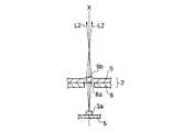
また、図3(図1のA−A断面図)に示すように、ハウジングケース1とカバーケース2によって形成された灯室10内に固定支持された部品実装基板6に実装された各白色LEDランプ3aの光軸Xと、カバーケース2を構成する光拡散層8の各LED光通過孔8aおよび光透過層9の各レンズ部9aの夫々の中心線は同一線上に位置している。 Further, as shown in FIG. 3 (A-A cross-sectional view in FIG. 1), each white LED mounted on a
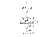
一方、図4(図1のB−B断面図)に示すように、ハウジングケース1とカバーケース2によって形成された灯室10内に固定支持された部品実装基板6に実装された各有色LED3bの光軸Xを中心とする近傍には、カバーケース2を構成する光拡散層8のLED光通過孔8aおよび光透過層9のレンズ部9aのいずれも設けられていない。 On the other hand, as shown in FIG. 4 (BB sectional view of FIG. 1), each colored
なお、図3および図4において、部品実装基板6のLEDランプ3が実装されている側には操作部品(図示せず)が実装されていると共に、部品実装基板6のLEDランプ3が実装されている側の反対側の面には電子部品5が実装されている。 3 and 4, an operation component (not shown) is mounted on the side of the
このような構成の自動車用室内灯において、図5(図4の部分断面図)に示すように、部品実装基板6の有色LEDランプ3bから放射された有色光のほとんどはカバーケース2の光拡散層8に至り、光拡散層8で拡散されて拡散光L1となって光透過層9に至り、光透過層9内を導光されて外部に照射される。 In the automotive interior light having such a configuration, most of the colored light emitted from the
よって、自動車用室内灯から照射される有色光は面輝度が比較的均一な柔らかい光質を呈し、車室内空間の演出効果を高める働きを有する。 Therefore, the colored light emitted from the interior lamp for the automobile exhibits a soft light quality with a relatively uniform surface luminance, and has a function of enhancing the effect of rendering the interior of the interior of the vehicle.
一方、図6(図3の部分断面図)に示すように、部品実装基板6の白色LEDランプ3aから放射された白色光または白色光に近い色調の光のうち、光軸Xを中心とする近傍に放射する光束密度が大きい光L2はカバーケース2の光拡散層8のLED光通過孔8aを通過して光透過層9のレンズ部9aに至り、レンズ部9aで集光されて外部に照射される。 On the other hand, as shown in FIG. 6 (partial sectional view of FIG. 3), the optical axis X is centered on the white light emitted from the
また、白色LEDランプ3aから放射された白色光または白色光に近い色調の光のうち、光軸Xを中心とする近傍から離れる方向に放射された光L3は、上記有色光と同様にカバーケース2の光拡散層8に至り、光拡散層8で拡散されて拡散光L3となって光透過層9に至り、光透過層9内を導光されて外部に照射される。 Of the white light emitted from the
よって、自動車用室内灯から照射される白色光または白色光に近い色調の光は、その多くが集光されて明るく且つ鮮明な光質の光スポットを形成して読書等の用に供される照明機能を果たすと共に、その一部は面輝度が比較的均一な柔らかい光質を呈して車室内空間の演出効果を高める働きをする。 Therefore, most of the white light emitted from the automotive interior light or light with a color tone close to white light is condensed to form a light spot with a bright and clear light quality and used for reading or the like. In addition to fulfilling the lighting function, a part of the light exhibits a soft light quality with a relatively uniform surface brightness, thereby enhancing the effect of the interior space.
なお、上記実施形態においては、光透過層9に形成されたレンズ部9aは光拡散層8のLED光通過孔8a側に膨らんだ湾曲面を有する形状とされていたが、図7に示すように、光透過層9に形成するレンズ部9bを光拡散層8のLED光通過孔8aに対応する位置のLED光通過孔8a側と反対側に膨らんだ湾曲面を有する形状としてもよい。 In the above embodiment, the
この場合も、部品実装基板6の白色LEDランプ3aから放射された白色光または白色光に近い色調の光のうち、光軸Xを中心とする近傍に放射する光束密度が大きい光L2はカバーケース2の光拡散層8のLED光通過孔8aを通過して光透過層9に至り、光透過層9内を導光されてレンズ部9bで集光されて外部に照射される。 Also in this case, among the white light emitted from the
また、図8に示すように、光透過層9に形成するレンズ部9a、9bを光拡散層8のLED光通過孔8aに対応する位置のLED光通過孔8a側およびLED光通過孔8a側と反対側の両方向に膨らんだ湾曲面を有する形状としてもよい。このとき、光透過層9の一方の方向に膨らんだレンズ部9aの夫々は光拡散層8の各LED光通過孔8a内に位置している。 Further, as shown in FIG. 8, the
するとこの場合も、部品実装基板6の白色LEDランプ3aから放射された白色光または白色光に近い色調の光のうち、光軸Xを中心とする近傍に放射する光束密度が大きい光L2はカバーケース2の光拡散層8のLED光通過孔8aを通過して光透過層9のレンズ部9aに至り、レンズ部9aで集光されて光透過層9内を導光され、更にレンズ部9bで集光されて外部に照射される。 In this case as well, among the white light emitted from the
ところで、上記実施形態においては、カバーケースの2層構造をLEDランプと対向する側に光拡散層が位置し、LEDランプと対向する側と反対側に光透過層が位置するようにしたが、この2層構造の位置関係を変えることも可能である。 By the way, in the said embodiment, although the light-diffusion layer was located in the 2 layer structure of a cover case on the side facing an LED lamp, and the light transmission layer was located on the opposite side to the side facing an LED lamp, It is also possible to change the positional relationship of this two-layer structure.
つまり、カバーケースの構成をLEDランプと対向する側に光透過層を位置させ、LEDランプと対向する側と反対側に光拡散層を位置させるものである。 That is, in the cover case, the light transmission layer is positioned on the side facing the LED lamp, and the light diffusion layer is positioned on the side opposite to the side facing the LED lamp.
この場合、図9に示すように、光透過層9に形成する複数のレンズ部9bを、光拡散層8のLED光通過孔8aに対応する位置において、光拡散層8のLED光通過孔8a側に膨らんだ湾曲面を有する形状とし、夫々のレンズ部9bの少なくとも一部が光拡散層8の各LED光通過孔8a内に位置するようにする。 In this case, as shown in FIG. 9, the plurality of
すると、部品実装基板6の白色LEDランプ3aから放射された白色光または白色光に近い色調の光のうち、光軸Xを中心とする近傍に放射する光束密度が大きい光L2はカバーケース2の光透過層9に至り、光透過層9内を導光されて光拡散層8のLED光通過孔8a内に位置するレンズ部9bで集光されて外部に照射される。 Then, among the white light radiated from the
あるいは、図10に示すように、光透過層9に形成するレンズ部9b、9aの夫々を光拡散層8のLED光通過孔8aに対応する位置において、光拡散層8のLED光通過孔8a側およびLED光通過孔8a側と反対側の両方向に膨らんだ湾曲面を有する形状とし、光透過層9の一方の方向に膨らんだレンズ部9bの夫々の少なくとも一部は光拡散層8の各LED光通過孔8a内に位置している。 Alternatively, as shown in FIG. 10, the LED light passage holes 8 a of the
するとこの場合も、部品実装基板6の白色LEDランプ3aから放射された白色光または白色光に近い色調の光のうち、光軸Xを中心とする近傍に放射する光束密度が大きい光L2はカバーケース2の光透過層9のレンズ部9aに至り、レンズ部9aで集光されて光透過層9内を導光され、光拡散層8のLED光通過孔8a内に位置するレンズ部9bで更に集光されて外部に照射される。 In this case as well, among the white light emitted from the
従って、図7〜図10の構成において、部品実装基板6の白色LEDランプ3aから放射された白色光または白色光に近い色調の光のうち、光軸Xを中心とする近傍に放射する光束密度が大きい光L2はいずれも明るく且つ鮮明な光質の光スポットを形成する。 Accordingly, in the configurations of FIGS. 7 to 10, the luminous flux density radiated in the vicinity of the optical axis X among the white light radiated from the
同様に、図7〜図10の構成において、部品実装基板6の有色LEDランプ3bから放射された光はいずれも比較的均一な柔らかい光質の拡散光を形成する。 Similarly, in the configurations of FIGS. 7 to 10, all the light emitted from the
以上説明したように、本発明の自動車用室内灯は、車室内において読書等の明るい光を必要とする場合には白色LEDランプからの白色光または白色光に近い色調の光による鮮明なスポット状の明りを提供し、車室内空間をムード照明する場合には有色LEDランプからの有色光による拡散された柔らかい明りを提供するものである。 As described above, the automotive interior light of the present invention has a clear spot shape due to white light from a white LED lamp or light having a color tone close to white light when bright light such as reading is required in the vehicle interior. When a vehicle interior space is mood-lit, a soft light diffused by colored light from a colored LED lamp is provided.
その結果、一台の自動車用室内灯によって照明機能と演出効果の両方を十分発揮する商品性の高い自動車用室内灯を実現することが可能となる。 As a result, it is possible to realize an automotive interior light with high merchantability that sufficiently exhibits both the illumination function and the rendering effect with a single automotive interior light.
1 ハウジングケース
2 カバーケース
3 LEDランプ
3a 白色LEDランプ
3b 有色LEDランプ
4 電子部品
5 操作部品
6 部品実装基板
7 光出射面
8 光拡散層
8a LED光通過孔
9 光透過層
9a レンズ部
9b レンズ部
10 灯室DESCRIPTION OF SYMBOLS 1
Claims (7)
Translated fromJapanesePriority Applications (2)
| Application Number | Priority Date | Filing Date | Title |
|---|---|---|---|
| JP2007165129AJP4837626B2 (en) | 2007-06-22 | 2007-06-22 | Automotive interior lights |
| US12/143,968US7954984B2 (en) | 2007-06-22 | 2008-06-23 | Interior lamp |
Applications Claiming Priority (1)
| Application Number | Priority Date | Filing Date | Title |
|---|---|---|---|
| JP2007165129AJP4837626B2 (en) | 2007-06-22 | 2007-06-22 | Automotive interior lights |
Publications (3)
| Publication Number | Publication Date |
|---|---|
| JP2009001196A JP2009001196A (en) | 2009-01-08 |
| JP2009001196A5 JP2009001196A5 (en) | 2010-07-29 |
| JP4837626B2true JP4837626B2 (en) | 2011-12-14 |
Family
ID=40136270
Family Applications (1)
| Application Number | Title | Priority Date | Filing Date |
|---|---|---|---|
| JP2007165129AExpired - Fee RelatedJP4837626B2 (en) | 2007-06-22 | 2007-06-22 | Automotive interior lights |
Country Status (2)
| Country | Link |
|---|---|
| US (1) | US7954984B2 (en) |
| JP (1) | JP4837626B2 (en) |
Families Citing this family (17)
| Publication number | Priority date | Publication date | Assignee | Title |
|---|---|---|---|---|
| JP5424457B2 (en)* | 2009-02-05 | 2014-02-26 | 矢崎総業株式会社 | Lighting fixture for vehicle with prism |
| JP2010228567A (en)* | 2009-03-26 | 2010-10-14 | Panasonic Electric Works Co Ltd | lighting equipment |
| AT509563B1 (en) | 2010-03-01 | 2015-10-15 | Hierzer Andreas | LIGHT WITH LIGHTING ELEMENTS |
| USD677824S1 (en)* | 2012-05-06 | 2013-03-12 | Lighting Science Group Corporation | Canopy light system |
| TW201411031A (en)* | 2012-09-07 | 2014-03-16 | Apm Communication Inc | T-BAR lamp |
| JP6292369B2 (en)* | 2013-04-18 | 2018-03-14 | 東芝ライテック株式会社 | Automotive interior lighting equipment |
| CN104633568B (en)* | 2013-11-13 | 2018-09-11 | 光阳工业股份有限公司 | Motorcycle headlight structure |
| US20150274066A1 (en)* | 2014-03-28 | 2015-10-01 | GM Global Technology Operations LLC | Vehicle trim panels with interior illumination systems |
| US10222029B2 (en) | 2014-09-30 | 2019-03-05 | The Boeing Company | Array-based lighting systems and methods of manufacturing |
| US9527437B2 (en)* | 2015-01-26 | 2016-12-27 | The Boeing Company | Lighting assembly for interior cabin of a vehicle |
| JP2017109507A (en)* | 2015-12-14 | 2017-06-22 | 矢崎総業株式会社 | Lighting device for vehicle ceiling |
| GB2547413B (en)* | 2016-02-08 | 2019-12-04 | Jaguar Land Rover Ltd | Lighting device |
| US10442350B2 (en)* | 2017-05-31 | 2019-10-15 | Ford Global Technologies, Llc | Vehicle interior light assembly with reflector and lens |
| CN109583381B (en)* | 2018-11-30 | 2020-11-10 | 京东方科技集团股份有限公司 | A texture recognition device and a self-luminous display panel |
| DE102019126019A1 (en)* | 2019-09-26 | 2021-04-01 | Lufthansa Technik Aktiengesellschaft | Lighting system for the cabin interior of a vehicle |
| JP7490973B2 (en)* | 2020-02-05 | 2024-05-28 | カシオ計算機株式会社 | Terminal device and program |
| JP7596237B2 (en)* | 2021-08-30 | 2024-12-09 | 矢崎総業株式会社 | Vehicle lighting device |
Family Cites Families (10)
| Publication number | Priority date | Publication date | Assignee | Title |
|---|---|---|---|---|
| DE3247449A1 (en)* | 1982-12-22 | 1984-07-05 | Ford-Werke AG, 5000 Köln | INTERIOR AND READING LAMP, IN PARTICULAR FOR MOTOR VEHICLES |
| US5508897A (en)* | 1994-04-01 | 1996-04-16 | Prince Corporation | Overhead lamp assembly |
| JP3849193B2 (en) | 1997-01-09 | 2006-11-22 | 市光工業株式会社 | Room lamp lighting device |
| US6897911B2 (en)* | 2000-02-14 | 2005-05-24 | Fuji Photo Film Co., Ltd. | Light diffusing plate, liquid crystal display apparatus and rear projection apparatus |
| JP2003127769A (en)* | 2001-10-22 | 2003-05-08 | Imasen Electric Ind Co Ltd | Automotive interior lights |
| US6851841B2 (en)* | 2001-11-28 | 2005-02-08 | Toyoda Gosei Co., Ltd. | Illumination device |
| JP2004256035A (en)* | 2003-02-27 | 2004-09-16 | Hayashi Telempu Co Ltd | Bright automotive interior materials |
| JP2005075316A (en)* | 2003-09-04 | 2005-03-24 | Toyoda Gosei Co Ltd | Lighting device |
| JP2005082106A (en)* | 2003-09-11 | 2005-03-31 | Toyoda Gosei Co Ltd | Lighting device |
| JP2006137330A (en)* | 2004-11-12 | 2006-06-01 | Toyoda Gosei Co Ltd | Outside handle for vehicle |
- 2007
- 2007-06-22JPJP2007165129Apatent/JP4837626B2/ennot_activeExpired - Fee Related
- 2008
- 2008-06-23USUS12/143,968patent/US7954984B2/ennot_activeExpired - Fee Related
Also Published As
| Publication number | Publication date |
|---|---|
| US20080316740A1 (en) | 2008-12-25 |
| US7954984B2 (en) | 2011-06-07 |
| JP2009001196A (en) | 2009-01-08 |
Similar Documents
| Publication | Publication Date | Title |
|---|---|---|
| JP4837626B2 (en) | Automotive interior lights | |
| US7293889B2 (en) | LED lamp apparatus | |
| JP5066462B2 (en) | Vehicle lighting | |
| KR20010032362A (en) | Motor vehicle light | |
| JP4191658B2 (en) | Vehicle lighting | |
| JP4831097B2 (en) | Vehicle interior lighting device | |
| US8096688B2 (en) | In-vehicle illumination device | |
| JP2005216782A (en) | LED lamp device | |
| JP2006138129A (en) | Outside handle of vehicle | |
| JP2003127769A (en) | Automotive interior lights | |
| JP3593065B2 (en) | Gaming machine lighting structure | |
| JP2007147621A (en) | Illuminating apparatus for display device of transportation means | |
| JP5305191B2 (en) | Gear shift display device | |
| JP2007115410A (en) | Rear combination lamp for vehicle | |
| JP2007103160A (en) | lighting equipment | |
| JP2011060884A (en) | Semiconductor light-emitting device and lighting fixture for vehicle | |
| JP5057818B2 (en) | Light emitting device | |
| CN222824188U (en) | A downlight | |
| JP2007080862A (en) | Light-emitting device | |
| JP2009241664A (en) | Vehicular lighting system | |
| JP6713135B1 (en) | Lighting equipment | |
| JP3113900U (en) | Automotive lamp | |
| JP6501203B2 (en) | Lighting device | |
| JP2023132847A (en) | Vehicular lighting fixture | |
| JP2022143807A (en) | Information presentation device and switch device |
Legal Events
| Date | Code | Title | Description |
|---|---|---|---|
| A521 | Written amendment | Free format text:JAPANESE INTERMEDIATE CODE: A523 Effective date:20100608 | |
| A621 | Written request for application examination | Free format text:JAPANESE INTERMEDIATE CODE: A621 Effective date:20100608 | |
| A977 | Report on retrieval | Free format text:JAPANESE INTERMEDIATE CODE: A971007 Effective date:20110830 | |
| TRDD | Decision of grant or rejection written | ||
| A01 | Written decision to grant a patent or to grant a registration (utility model) | Free format text:JAPANESE INTERMEDIATE CODE: A01 Effective date:20110906 | |
| A01 | Written decision to grant a patent or to grant a registration (utility model) | Free format text:JAPANESE INTERMEDIATE CODE: A01 | |
| A61 | First payment of annual fees (during grant procedure) | Free format text:JAPANESE INTERMEDIATE CODE: A61 Effective date:20110928 | |
| FPAY | Renewal fee payment (event date is renewal date of database) | Free format text:PAYMENT UNTIL: 20141007 Year of fee payment:3 | |
| R150 | Certificate of patent or registration of utility model | Ref document number:4837626 Country of ref document:JP Free format text:JAPANESE INTERMEDIATE CODE: R150 Free format text:JAPANESE INTERMEDIATE CODE: R150 | |
| R250 | Receipt of annual fees | Free format text:JAPANESE INTERMEDIATE CODE: R250 | |
| R250 | Receipt of annual fees | Free format text:JAPANESE INTERMEDIATE CODE: R250 | |
| R250 | Receipt of annual fees | Free format text:JAPANESE INTERMEDIATE CODE: R250 | |
| R250 | Receipt of annual fees | Free format text:JAPANESE INTERMEDIATE CODE: R250 | |
| R250 | Receipt of annual fees | Free format text:JAPANESE INTERMEDIATE CODE: R250 | |
| LAPS | Cancellation because of no payment of annual fees |