JP4836825B2 - Multi-screen display system - Google Patents
Multi-screen display systemDownload PDFInfo
- Publication number
- JP4836825B2 JP4836825B2JP2007034935AJP2007034935AJP4836825B2JP 4836825 B2JP4836825 B2JP 4836825B2JP 2007034935 AJP2007034935 AJP 2007034935AJP 2007034935 AJP2007034935 AJP 2007034935AJP 4836825 B2JP4836825 B2JP 4836825B2
- Authority
- JP
- Japan
- Prior art keywords
- video
- screen
- control
- network
- display system
- Prior art date
- Legal status (The legal status is an assumption and is not a legal conclusion. Google has not performed a legal analysis and makes no representation as to the accuracy of the status listed.)
- Expired - Fee Related
Links
Images


Landscapes
- Controls And Circuits For Display Device (AREA)
- Telephonic Communication Services (AREA)
- Digital Computer Display Output (AREA)
- Transforming Electric Information Into Light Information (AREA)
Description
Translated fromJapanese本発明は、マルチスクリーン表示システムに係り、特に、マルチスクリーンと映像機器制御用計算機とをネットワークで接続し、ネットワークプロトコルに基づいて前記映像機器制御用計算機から前記マルチスクリーンを制御するようにしたマルチスクリーン表示システムに関する。 The present invention relates to a multi-screen display system, in particular, a multi-screen connected to a video device control computer via a network, and the multi-screen is controlled from the video device control computer based on a network protocol. The present invention relates to a screen display system.
マルチスクリーン表示システムは、複数の計算機(例えば、ワークステーション;WS)において描画アプリケーションを実行して生成した映像を、任意の位置に必要により拡大して表示できるようにしたシステムであり、近年、発電、変電、給電あるいは送配電等のシステムのプロセス監視・制御用ディスプレイとして利用されている。 The multi-screen display system is a system in which a video generated by executing a drawing application on a plurality of computers (for example, a workstation; WS) can be enlarged and displayed at an arbitrary position as necessary. It is used as a display for process monitoring and control in systems such as substations, power feeding or power transmission / distribution.
従来のマルチスクリーン表示システムは、複数の計算機(WS)で生成された映像を画像切替器や映像拡大装置を介してマルチスクリーンに表示させるように構成されており、しかも、画像切替器や映像拡大装置の制御を行うマルチスクリーン制御装置とマルチスクリーン切替スイッチとをRS−232Cケーブル等の中低速のシリアル信号線によって接続されている。このように構成されたマルチスクリーン表示システムでは、マルチスクリーン制御装置に電気的に接続された切替スイッチでしかマルチスクリーンの制御ができないという欠点があった。 A conventional multi-screen display system is configured to display video generated by a plurality of computers (WS) on a multi-screen via an image switcher and a video enlargement device, and further, an image switcher and a video magnifier. A multi-screen control device that controls the device and a multi-screen changeover switch are connected by a medium-low speed serial signal line such as an RS-232C cable. The multi-screen display system configured as described above has a drawback in that multi-screen control can be performed only by a changeover switch electrically connected to the multi-screen control device.
また、このような課題を解決するために、映像を生成する計算機(WS)に対してTCP/IPによるネットワークを介してマルチスクリーン制御用計算機を接続し、このマルチスクリーン制御用計算機に更に制御装置を接続し、この制御装置をRS−232Cケーブル等の中低速用信号線を介して画像拡大装置や画像切替器に接続するようにしたマルチスクリーン表示システムが発明されている(例えば、特許文献1参照)。
しかしながら、この特許文献1に記載のマルチスクリーン表示システムは、映像信号線によって計算機(WS)から画像切替器に直接映像信号を出力しているために、当該計算機(WS)の設置場所に制約があるだけではなく、計算機(WS)毎に映像出力数分の映像信号線が必要となる。 However, since the multi-screen display system described in
また、マルチスクリーン制御用計算機と画像拡大装置または画像切替器間、または制御装置とマルチスクリーン制御用計算機間、制御装置と画像拡大装置、画像切替器間をそれぞれ接続するRS−232Cケーブル等の中低速用シリアル信号線は伝送距離に制限がある(一般に、信号線の最大長は約15m程度といわれている)ため、各装置の設置場所にも制約を受ける。
さらに、マルチスクリーン制御装置は1台しか設けられていないため、これに故障が発生するとマルチスクリーン表示システムが制御不能に陥ってしまう。Also, among the RS-232C cables that connect the multi-screen control computer and the image enlarging device or the image switcher, or between the control device and the multi-screen control computer, and between the control device and the image enlarging device and the image switcher, respectively. Since the low-speed serial signal line has a limited transmission distance (generally, the maximum length of the signal line is said to be about 15 m), the installation location of each device is also restricted.
Furthermore, since only one multi-screen control device is provided, if a failure occurs in this, the multi-screen display system becomes uncontrollable.
本発明は上述した従来技術の課題を解決するためになされたものであり、映像を生成する計算機毎の映像出力数分の映像信号線を必要とせず、しかも映像切替器、映像拡大器、マルチスクリーン等の制御対象機器と制御用計算機等の制御装置との設置場所に関する制約を軽減し、1台の制御用計算機等に故障が発生しても制御不能に陥りにくいようにしたマルチスクリーン表示システムを得ることを目的とする。 The present invention has been made to solve the above-described problems of the prior art, and does not require as many video signal lines as the number of video outputs for each computer that generates video, and further includes a video switcher, video expander, A multi-screen display system that reduces restrictions on the installation location of devices to be controlled such as screens and control devices such as control computers, and makes it difficult to control even if one control computer fails. The purpose is to obtain.
上記の目的を達成するために、請求項1に係るマルチスクリーン表示システムの発明は、描画アプリケーションを実行して表示すべき映像信号を送る描画要求クライアントと、描画要求用ネットワークを介して前記描画要求クライアントに接続されるとともに、当該描画要求クライアントからの描画要求に基づいて複数の映像信号を出力し、仮想的な大画面を構成することが可能な描画表示サーバと、前記描画表示サーバから出力される複数の映像信号を入力し、当該複数の映像信号の中から、指定された映像信号を出力する映像切替器と、前記映像切替器から出力される映像信号を入力し、当該複数の映像信号の中から、指定された映像入力を拡大処理する映像拡大器と、複数の画面を備え、前記映像切替器または前記映像拡大器から出力される映像信号を入力して表示するマルチスクリーンと、制御対象機器である前記映像切替器、前記映像拡大器および前記マルチスクリーンに映像機器用ネットワークを介して接続されるとともに、当該映像機器用ネットワークを通して制御データを送信して前記映像切替器、前記映像拡大器および前記マルチスクリーンを選択し、かつ選択された制御対象機器の状態情報を当該映像機器用ネットワークを通して取得する映像機器制御手段を有する映像機器制御用計算機と、を備えたことを特徴とする。 In order to achieve the above object, the invention of the multi-screen display system according to
本発明によれば、映像機器制御用計算機とマルチスクリーン、映像切替器、映像拡大器等の制御対象機器との間を映像機器制御用LANケーブルにより接続されているため、映像機器制御用計算機の設置場所にも制約は無く自由な設置が可能となる。 According to the present invention, the video equipment control computer and the control target equipment such as the multi-screen, video switcher, video magnifier and the like are connected by the video equipment control LAN cable. There are no restrictions on the installation location, and free installation is possible.
さらに、映像機器制御用計算機の設置台数に1台という制約はないため複数台の設置が可能であり、映像機器制御用計算機のうちの1台に故障が発生したとしても、他の映像機器制御用計算機から制御および状態情報取得を行うことができ、従来システムのように制御不能となることはない。 Furthermore, since there is no restriction on the number of video equipment control computers to be installed, a plurality of video equipment control computers can be installed. Even if one of the video equipment control computers fails, other video equipment control is possible. Control and status information acquisition can be performed from a computer, and control is not disabled unlike conventional systems.
以下、本発明に係るマルチスクリーン表示システムの各実施の形態について、図面を参照して説明する。なお、各図を通して同一対象部分には同一符号を付けることによって、重複する説明は極力省略する。 Embodiments of a multi-screen display system according to the present invention will be described below with reference to the drawings. In addition, the overlapping description is abbreviate | omitted as much as possible by attaching | subjecting the same code | symbol to the same object part through each figure.
(実施の形態1)
[構成]
本実施の形態1について図1ないし図5を参照して説明する。
図1は本実施の形態1におけるマルチスクリーン表示システムのブロック構成図、図2は映像機器制御用計算機の映像機器制御手段のブロック構成図、図3はマルチスクリーンに表示される全ての映像とマルチスクリーン上で表示される画面に対応した映像切替制御シナリオの管理表の一例を示す図、図4は状態情報取得シナリオで取得される各機器の状態の一例を示す図、そして、図5は状態情報取得シナリオにより作成された映像状態表の一例を示す図である。(Embodiment 1)
[Constitution]
The first embodiment will be described with reference to FIGS.
FIG. 1 is a block diagram of a multi-screen display system according to the first embodiment, FIG. 2 is a block diagram of video equipment control means of a video equipment control computer, and FIG. 3 shows all videos and multi-screens displayed on the multi-screen. The figure which shows an example of the management table | surface of the video switching control scenario corresponding to the screen displayed on a screen, FIG. 4 is a figure which shows an example of the state of each apparatus acquired by a state information acquisition scenario, and FIG. It is a figure which shows an example of the image | video state table produced by the information acquisition scenario.
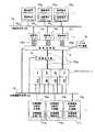
まず、図1を参照して説明する。
16a、16b、16c、・・・は描画要求クライアントであり、描画要求用ネットワーク(以下、描画要求用LANケーブルという)19を介して描画表示サーバ17a、17b、17c、・・・に接続されている。描画要求クライアント16a、16b、16c、・・・は、予めインストールしてある描画要求アプリケーション16−1a、16−1b、16−1c、・・・を実行して描画要求を行う映像データを生成し、ネットワークプロトコル(例えば、Xプロトコル;X Window Systemで採用されているプロトコル)を使用して描画表示サーバ17a、17b、17c、・・・に対して映像の描画要求を行うように構成されている。First, a description will be given with reference to FIG.
描画表示サーバ17a、17b、17c、・・・は、それぞれ1または複数の映像信号線PS1によって映像切替器15と接続されており、1つの映像信号線はマルチスクリーン13を構成する1つの画面へ表示する映像信号を伝送する。このため、描画表示サーバ17a、17b、17c、・・・は、複数の映像信号線PS1により仮想的な大画面を構成することが可能になっている。 The
前述の映像切替器15は、映像信号線PS2によりマルチスクリーン13および映像拡大器14と接続されており、映像信号線PS1を通して入力された複数の映像信号の中から、後述する映像機器制御用計算機10a、10b、10c、・・・によって指定された映像信号を、前述の映像信号線PS2を通してマルチスクリーン13または映像拡大器14に送信するように機能する。また、映像拡大機器14は映像信号線PS2によりマルチスクリーン13にも接続されており、受信した映像信号を拡大処理した後、映像信号線PS2を通してマルチスクリーン13に送信するように機能する。 The
そして、これらマルチスクリーン13、映像拡大機器14および映像切替器15等の制御対象機器は、それぞれ制御信号用入出力ポート(LANポート)に映像機器制御用のネットワーク(以下、映像機器制御用LANケーブルという)12のプラグを差し込むことにより、その映像機器制御用LANケーブル12を介して映像機器制御用計算機10a、10b、10c、・・・と接続される。 The devices to be controlled such as the multi-screen 13, the
この映像機器制御用計算機10a、10b、10c、・・・は、制御対象機器であるマルチスクリーン13、映像拡大機器14および映像切替器15の制御と、その状態情報の取得をするための手順を定めた映像機器制御用ソフトウェア(以下、映像機器制御手段という)11a、11b、11c、・・・をインストールしている。そして、映像機器制御用計算機10a、10b、10c、・・・は、ネットワークプロトコル(例えば、TCP/IPやUDP/IPなど)を使用して、制御対象機器であるマルチスクリーン13、映像拡大機器14および映像切替器15に制御データを送信して選択し、さらに選択した制御対象機器13、14および15の状態情報の取得は状態情報取得データの受信により行う。
18は、例えばVTR、DVD再生装置などに代表されるビデオ出力機器であり、映像信号線PS1を介して映像切替器15に接続されている。The video
[作用]
次に、図1ないし図5を参照して本実施の形態の作用を説明する。
描画要求クライアント16a〜16c、・・・は、それぞれ描画要求アプリケーション16−1a、16−1b、16−1c、・・・を実行することによって描画要求を行う映像データを生成し、描画要求用LANケーブル19を経由して描画表示サーバ17a、17b、17c、・・・に対して仮想的な大画面への表示要求を行う。[Action]
Next, the operation of the present embodiment will be described with reference to FIGS.
Drawing requesting
本実施の形態1では、各描画表示サーバ17a、17b、17c、・・・は4本の映像信号線PS1により映像切替器15と接続されており、1本の映像信号線PS1に対応する画面サイズが横;1280ピクセル、縦;1024ピクセルの場合、仮想的な大画面の画面サイズは、横;2560ピクセル、縦;2048ピクセルとなる。そして、各描画表示サーバ17a、17b、17c、・・・は、仮想的な大画面の表示要求をするとき、表示要求と、描画要求対象映像データの描画開始点、縦方向の画面長、横方向の画面長からなる描画サイズとを併せて行う。描画表示サーバ17a、17b、17c、・・・は、仮想的な大画面へ描画要求を受けた映像データの分割を行い、分割した映像データを映像信号線PS1毎に映像切替器15への入力信号として出力する。 In the first embodiment, each
図2は映像機器制御用計算機10aにインストールされている映像機器制御手段11aの一構成例を示す。この映像機器制御手段11aは、映像切替制御シナリオ11−1、状態情報取得シナリオ11−2およびシナリオ実行エンジン11−3から構成されている。FIG. 2 shows a configuration example of the video equipment control means 11a installed in the video
映像切替制御シナリオ11−1は、マルチスクリーン13に表示される映像の切替をシナリオ化したものであり、マルチスクリーン13に表示される映像と、その映像がマルチスクリーン13上のどの画面(図1では画面1〜画面8)を使用して表示するのか、その組み合わせ毎に映像切替時に制御すべき機器と制御内容とを記述したものである。
また、状態情報取得シナリオ11−2は、マルチスクリーン13を構成する画面、映像拡大機器14および映像切替器15の状態に関する情報の取得処理を記述したものである。The video switching control scenario11-1 is a scenario for switching video displayed on the multi-screen 13, and the video displayed on the multi-screen 13 and which screen on the multi-screen 13 (FIG. 1). Then, the
In addition, the state information acquisition scenario11-2 describes a process for acquiring information regarding the states of the screens constituting the multi-screen 13, the
そして、シナリオ実行エンジン11−3は、映像機器制御用計算機10a上で動作しているアプリケーションからの映像切替要求aおよび状態情報の取得要求bを受け取り、対応した映像切替制御シナリオ11−1または状態情報取得シナリオ11−2を実行し、映像切替または状態情報取得を行う。Then, the scenario execution engine11-3 receives the video switching request a and the status information acquisition request b from the application operating on the video
図3はマルチスクリーン13に表示される全ての映像と、マルチスクリーン13上で表示される画面に対応した映像切替制御シナリオとを管理するための管理表であり、3つの欄すなわち、「映像名称」、「画面名称」および「映像切替制御シナリオ」の欄を有している。 FIG. 3 is a management table for managing all videos displayed on the multi-screen 13 and video switching control scenarios corresponding to the screens displayed on the multi-screen 13, and includes three columns, namely “video name”. ”,“ Screen name ”, and“ video switching control scenario ”.
この図3の管理表によれば、マルチスクリーン13に表示される全ての映像には「映像名称」を、マルチスクリーン13上で表示される画面には「画面名称」を付与することで、対応する「映像切替制御シナリオ」を一意に識別することができるようになっている。 According to the management table of FIG. 3, “video name” is assigned to all videos displayed on the multi-screen 13, and “screen name” is assigned to the screen displayed on the multi-screen 13. It is possible to uniquely identify the “video switching control scenario” to be performed.
「画面名称」欄における「画面1」、「画面2」、…「画面8」はそれぞれマルチスクリーン13を構成する8つの画面に付与された番号1、2、…8に対応するものであり、また、「左4面」とはマルチスクリーン13を構成する画面に付与された番号1〜4までの4つの画面を示し、これに対応する映像名称が指定された場合には左4面すなわち、画面1〜4画面に拡大表示が行わる。なお、図3中には示していないが、「右4面」と指定された場合にはマルチスクリーン13を構成する画面に付与された番号5〜8までの4つの画面で拡大表示が行わることを意味する。 “
描画表示サーバ17aから出力された映像データを、マルチスクリーン13の画面8面のうち左4面(画面1〜画面4)で表示する場合には、図2の映像機器制御用計算機10aにインストールされている映像機器制御手段11aのシナリオ実行エンジン11−3によって図3中の「映像切替制御シナリオ1」が実行される(符合“1”)。When the video data output from the
「シナリオ1」には、映像切替器15へ入力された描画表示サーバ17aからの映像信号PS1をマルチスクリーン13の左側4面(画面1〜画面4)へ出力するための切替処理として映像切替器15の切替処理内容が記述されており、これを実行することにより切替制御が行われる。 In “
ビデオ出力機器18の映像をマルチスクリーン13の「画面1」に表示する場合は、同様にして、映像機器制御用計算機10aの映像機器制御手段11aのシナリオ実行エンジン11−3により、図3の管理表中で対応する「映像切替制御シナリオ5」が実行される(符合“2”)。When displaying the image of the
「シナリオ5」には、映像切替器15へ入力されたビデオ出力機器18からの映像信号PS1をマルチスクリーン13の「画面1」へ出力するための切替処理として映像切替器15の切替処理内容が記述されており、これを実行することにより切替制御が行われる。 “
ビデオ出力機器18の映像をマルチスクリーン13の画面8面のうち「左4面」に拡大表示する場合には、映像機器制御用計算機10aの映像機器制御手段11aのシナリオ実行エンジン11−3により、図3の管理表で対応する「映像切替制御シナリオ4」が実行される(符合“3”)。When magnify the image of the
「シナリオ4」には、映像切替器15へ入力されたビデオ出力機器18からの映像信号PS1をマルチスクリーン13の左側4面(画面1〜画面4)へ出力するための切替処理として映像切替器15の切替処理内容が記述されており、これを実行することにより切替制御が行われる。 In “
マルチスクリーン13に表示されている映像情報の取得、マルチスクリーン13を構成する画面、映像拡大機器14および映像切替器15の状態情報の取得を行う場合には、映像機器制御用計算機10aにインストールされている映像機器制御手段11aのシナリオ実行エンジン11−3により状態情報取得シナリオ11−2が実行される。When acquiring the video information displayed on the multi-screen 13, the screens constituting the multi-screen 13, and the status information of the
この状態情報取得シナリオ11−2は、マルチスクリーン13を構成する画面、映像拡大機器14および映像切替器15の状態情報取得を映像機器制御用LANケーブル12を介して行い、各制御対象機器13〜15の状態と表示画面構成表とを作成する。In this status information acquisition scenario11-2, the status information of the screens constituting the multi-screen 13, the
図4は図2に示す状態情報取得シナリオ11−2で取得される各制御対象機器13〜15の状態の一例を示す図である。
図4(a)は映像切替器15の状態を示す図であり、映像切替器15から出力される各映像信号毎にどの入力映像信号が使用されているのかを示す。例えば、出力される映像信号の番号が「1」の場合は、入力映像信号は番号「10」が使用され、映像信号の番号が「2」の場合は、入力映像信号は番号「8」が使用されていることを示している。Figure 4 is a diagram showing an example of the state of the control target device 13-15 which is acquired by the status information acquisition scenario11-2 shown in FIG.
FIG. 4A is a diagram showing the state of the
図4(b)は映像拡大器14の状態を示す図であり、図示の場合は映像の拡大が行われている状態を示す。図4(c)はマルチスクリーン13画面1の状態、すなわち、電源状態、ランプ状態、ランプ使用時間、ファン状態、・・・映像状態等、画面を構成する機器に応じた状態を示す図であり、例えば、電源;ON、ランプ;ON、ランプ使用時間;100H、ファン;故障、・・・映像状態;ミュート中、の各状態を図示している。 FIG. 4B is a diagram showing the state of the
図2に示す状態情報取得シナリオ11−2が実行されると、各制御対象機器について上述した図4の状態取得情報を作成し、さらにこの状態取得情報を用いて、現在のマルチスクリーン13に表示されている映像を判別し、図5に示す映像状態表を作成する。マルチスクリーン13に表示されている映像の判別は、図3に示した「映像切替制御シナリオ」と同様に、各機器の状態から一意に判別することができる。When the state information acquisition scenario11-2 shown in FIG. 2 is executed, the state acquisition information of FIG. 4 described above is created for each control target device, and further displayed on the current multi-screen 13 using this state acquisition information. The video that has been recorded is discriminated, and the video status table shown in FIG. The video displayed on the multi-screen 13 can be uniquely determined from the state of each device, as in the “video switching control scenario” shown in FIG.
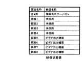
図5は状態情報取得シナリオ11−2により作成された映像状態表であり、「画面名称」および「映像名称」の2つの欄を有している。
「画面名称」で示されるマルチスクリーン13の画面に現在表示されている映像名称が記載される。例えば、図5の場合画面1〜画面4で構成される「左4面」に描画表示サーバ17aの映像が拡大表示され、画面5、画面6、画面7および画面8にはそれぞれにビデオ出力機器18の映像が表示されていることを表している。なお、画面1、画面2、画面3、画面4については「左4面」に映像が拡大表示されているため「未使用」という扱いである。Figure 5 is a video state table created by the state information acquisition scenario11-2 has two column "screen name" and "image name".
The video name currently displayed on the screen of the multi-screen 13 indicated by “screen name” is described. For example, in the case of FIG. 5, the video of the
図2に示すシナリオ実行エンジン11−3は、状態情報取得シナリオ11−2を実行することにより、各制御対象機器の状態およびマルチスクリーン13に現在表示されている映像の状態情報を取得することができる。取得した状態情報をもとにアプリケーション向けのAPI(Application Program Interface)またはGUI(Graphical User Interface)表示により現在のマルチスクリーン13および他の各制御対象機器の状態をユーザーに通知することが可能である。The scenario execution engine11-3 shown in FIG. 2 can acquire the state information of the devices to be controlled and the state information of the video currently displayed on the multi-screen 13 by executing the state information acquisition scenario11-2. it can. Based on the acquired status information, it is possible to notify the user of the current status of the multi-screen 13 and other control target devices by API (Application Program Interface) or GUI (Graphical User Interface) display for applications. .
[効果]
以上述べたように、本実施の形態1によれば、描画要求クライアント16および描画表示サーバ17間が描画要求用LANケーブル19により接続されているため、描画表示サーバ17の設置場所には制約が無く自由な設置が可能となる。また、映像機器制御用計算機10とマルチスクリーン13、映像切替器15、映像拡大器14との間も映像機器制御用LANケーブル12により接続されているため、映像機器制御用計算機10の設置場所にも制約は無く自由な設置が可能となる。[effect]
As described above, according to the first embodiment, since the
さらに、映像機器制御用計算機10a、10b、10c、・・・の設置台数に1台という制約はなく、複数台の設置が可能であるため、たとえ、映像機器制御用計算機のうちの1台に故障が発生したとしても、他の映像機器制御用計算機から制御および状態情報取得を行うことができ、したがって、従来システムのように制御不能となることなくマルチスクリーン表示システムの運用を行うことができる。 Further, there is no restriction on the number of video
(実施の形態2)
[構成]
次に、本発明の実施の形態2について図6を参照して説明する。
図6は、本発明の実施の形態2におけるマルチスクリーン表示システムのブロック構成図である。(Embodiment 2)
[Constitution]
Next,
FIG. 6 is a block configuration diagram of the multi-screen display system according to the second embodiment of the present invention.
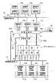
本実施の形態2は、マルチスクリーン13、映像拡大機器14および映像切替器15等の制御対象機器の制御信号用入出力ポートに映像機器制御用LANケーブル12のプラグを直接接続する代わりに、制御信号用入出力ポートにRS−232Cケーブル等のシリアル信号線60のプラグを接続し、このシリアル信号線60と映像機器制御用LANケーブル12との間にプロトコル変換器61を介挿させることによって、マルチスクリーン13、映像拡大機器14および映像切替器15等の制御対象機器と、映像機器制御用計算機10a、10b、10c、・・・との間で情報の送受信が行えるように構成したものである。 In the second embodiment, instead of directly connecting the plug of the video device
プロトコル変換器61は、RS−232CのシリアルインターフェースおよびLANインターフェースを有しており、映像機器制御用計算機10a、10b、10c、・・・から映像機器制御用LANケーブル12に送出されたデータ内容をLANインターフェースでプロトコル変換してシリアル信号線60を経て制御対象機器13〜15に送出する機能と、各制御対象機器13、14、15から送出されたデータ内容をシリアルインターフェースでプロトコル変換して映像機器制御用LANケーブル12を経て映像機器制御用計算機10a、10b、10c、・・・に送出する機能とを備えている。その他の構成は、前述した実施の形態1と同じである。 The
[作用]
本実施の形態2において、マルチスクリーン13、映像拡大機器14および映像切替器15の制御および状態情報の取得を行う場合には、実施の形態1と同様に、映像機器制御用計算機10a、10b、10c、・・・の映像機器制御手段11a、11b、11c、・・・により、映像機器制御用LANケーブル12を介してマルチスクリーン13、映像拡大機器14、映像切替器15にそれぞれ接続されたプロトコル変換器61へ制御、状態情報取得の要求を送信する。[Action]
In the second embodiment, when the control of the multi-screen 13, the
すると、プロトコル変換器61は、受信した要求内容をシリアル通信用のデータに変換し、シリアル信号線60を介してマルチスクリーン13、映像拡大機器14および映像切替器15等へ送信する。 Then, the
逆に、マルチスクリーン13、映像拡大機器14および映像切替器15は、受信した制御、状態情報取得の要求に応じて処理を実施し、その処理の実施結果または機器の状態情報をシリアル信号線60を経てプロトコル変換器61へ送信する。 Conversely, the multi-screen 13, the
プロトコル変換器61はマルチスクリーン13、映像拡大機器14および映像切替器15から送信された実施結果、機器の状態情報をLAN通信用のデータに変換し、映像制御用LANケーブル12を経て映像機器制御用計算機10a、10b、10c、・・・へ送信する。この結果、マルチスクリーン13、映像拡大機器14および映像切替器15から送信された処理の実施結果または機器の状態情報は、映像機器制御用計算機10a、10b、10c、・・・の映像機器制御手段11a、11b、11c、・・・で受信される。 The
[効果]
以上述べたように、本実施の形態2によれば、制御対象機器であるマルチスクリーン13、映像拡大機器14、映像切替器15がLANインターフェースを有していない場合にもプロトコル変換器61を介してLANケーブル経由で制御、状態情報の取得を行うことが可能となり、映像機器制御用計算機10a、10b、10c、・・・とプロトコル変換器61との間はネットワーク12により接続されているため、実施の形態1と同様に映像機器制御用計算機10a、10b、10c、・・・の設置場所に制約は無く自由な設置が可能となる。[effect]
As described above, according to the second embodiment, even when the multi-screen 13, the
(実施の形態3)
[構成]
次に、本発明の実施の形態3について図7を参照して説明する。
図7は、本発明の実施の形態3におけるマルチスクリーン表示システムのブロック構成図である。(Embodiment 3)
[Constitution]
Next,
FIG. 7 is a block configuration diagram of a multi-screen display system according to
本実施の形態3は、実施の形態1において映像機器制御用計算機10a、10b、10c、・・・とは独立して設置されている描画要求クライアント16a、16b、16c、・・・にインストールされている描画要求アプリケーション機能16−1a、16−1b、16−1c、・・・を、映像機器制御用計算機10a、10b、10c、・・・にインストールしたものである。The third embodiment is installed in the
すなわち、描画要求を行うクライアント(計算機)を映像機器の制御を行う映像機器制御用計算機10a、10b、10c、・・・に統合して1つの計算機とすることにより、その統合した映像機器制御用計算機10a、10b、10c、・・・に描画要求アプリケーション機能16−1a、16−1b、16−1c、・・・と、映像機器制御手段11a、11b、11c、・・・とをそれぞれインストールするとともに、描画要求用LANケーブル19を描画要求アプリケーション16−1a、16−1b、16−1c、・・・に接続して情報の送受信を可能にしたものである。That is, by integrating a client (computer) that makes a drawing request into video
本実施の形態3では、これに加えて、マルチスクリーン表示システムの操作を訓練するための訓練卓70a、・・・70nを新たに備えており、この訓練卓70a、・・・70nから映像信号線PS1により映像切替器15に接続するとともに、映像切替器15から映像信号線PS2により卓70a、・・・70nに接続するようにしている。その他の構成は、前述した実施の形態1と同じである。 In addition to this, the third embodiment further includes training tables 70a,... 70n for training the operation of the multi-screen display system, and video signals are output from the training tables 70a,. In addition to being connected to the
なお、ここでは訓練卓の例を用いて説明するが、訓練卓以外の、制御卓、操作卓等のように、システムの監視・制御操作を行う卓についても本実施の形態を適用することができる。 In addition, although it demonstrates using the example of a training table here, this Embodiment can be applied also to the table which performs monitoring and control operation of a system like a control table, an operation console, etc. other than a training table. it can.
[作用]
本実施の形態3は、映像機器制御用計算機10aの描画要求アプリケーション16−1aにて描画表示サーバ17aへ描画要求した映像をマルチスクリーン13へ表示させる場合、描画要求アプリケーション16−1aより表示サーバ17aへ描画要求を行うとともに、描画要求アプリケーション16−1aより映像機器制御手段11aを用いて描画表示サーバ17aより出力された映像データをマルチスクリーン13へ表示する切替制御を行う。[Action]
In the third embodiment, when the drawing request application16-1a of the video
また、万一、描画表示サーバ17aが故障して描画要求を受け付けない場合は、映像機器制御用計算機10aの描画要求アプリケーション16−1aにて描画表示サーバ17bへ描画要求を行うとともに、描画要求アプリケーション16−1aより映像機器制御手段11aを用いて、描画表示サーバ17bより出力された映像データをマルチスクリーン13へ表示する切替制御を行う。If the
なお、訓練卓70a、・・・70nにはトレーナ用とトレーニ用とがあり、トレーニによるマルチスクリーンシステムの操作内容を自己の訓練卓のモニターに表示するとともに、トレーナの訓練卓のモニターにも表示されるようになっている。 The training tables 70a,... 70n are for trainers and trainees, and the operation details of the multi-screen system by the trainees are displayed on the monitor of their own training table and also displayed on the monitor of the trainer's training table. It has come to be.
[効果]
本実施の形態3によれば、描画要求を行う計算機と映像機器の制御を行う計算機とを1つの計算機に統合したので、映像機器制御用計算機の設置場所に関する制約がなく、より自由に設置できる。また、描画表示サーバ17a、17b、17c、・・・、マルチスクリーン13を構成する画面の故障が発生した場合にも描画要求先の描画表示サーバの変更および映像切替処理を連動して行うことが可能となり、一部機器の故障が発生しとしてもマルチスクリーン表示システム全体への影響を少なくすることができる。[effect]
According to the third embodiment, since the computer that performs the drawing request and the computer that controls the video equipment are integrated into one computer, there is no restriction on the installation location of the video equipment control computer, and it can be installed more freely. . In addition, even when a failure of the screens constituting the
(他の実施の形態)
なお、本発明は以上説明した実施の形態1〜3に限定されるものではなく、例えば、映像機器制御用LANケーブル12と描画要求用LANケーブル19とを同一のセグメントLANとしてもよい。(Other embodiments)
The present invention is not limited to the first to third embodiments described above. For example, the video equipment
また、マルチスクリーン13に映像切替機能および映像拡大機能を持たせることができる場合には、映像拡大機器14および映像切替器15を独立して設けずに、マルチスクリーン13内に組み込むように構成することもできる。 If the multi-screen 13 can be provided with a video switching function and a video magnification function, the
10a、10b、10c、・・・;映像機器制御用計算機、11a、11b、11c、・・・;映像機器制御用ソフトウェア(映像機器制御手段)、12;映像機器制御用のネットワーク(映像機器制御用LANケーブル)、13;マルチスクリーン、14;映像拡大機器、15;映像切替器、16a、16b、16c、・・・;描画要求クライアント、16−1a、16−1b、16−1c、・・・;描画要求アプリケーション、17a、17b、17c、・・・;描画表示サーバ、18;ビデオ出力機器、19;描画要求用のネットワーク(描画要求用LANケーブル)、60;シリアル信号線、61;プロトコル変換器、70;訓練卓。10a, 10b, 10c,...; Video equipment control computer, 11a, 11b, 11c,...; Video equipment control software (video equipment control means), 12; video equipment control network (video equipment control) use LAN cable), 13; multi-screen, 14; image enlargement device, 15; video switcher, 16a, 16b, 16c, · · ·, drawing requestclient, 16 -1a, 16 -1b, 16 -1c, ·· Drawing request application, 17a, 17b, 17c,...; Drawing display server, 18; Video output device, 19; Network for drawing request (LAN cable for drawing request), 60; Serial signal line, 61; Transducer, 70; training table.
Claims (6)
Translated fromJapanese描画要求用ネットワークを介して前記描画要求クライアントに接続されるとともに、当該描画要求クライアントからの描画要求に基づいて複数の映像信号を出力し、仮想的な大画面を構成することが可能な描画表示サーバと、
前記描画表示サーバから出力される複数の映像信号を入力し、当該複数の映像信号の中から、指定された映像信号を出力する映像切替器と、
前記映像切替器から出力される映像信号を入力し、当該複数の映像信号の中から、指定された映像入力を拡大処理する映像拡大器と、
複数の画面を備え、前記映像切替器または前記映像拡大器から出力される映像信号を入力して表示するマルチスクリーンと、
制御対象機器である前記映像切替器、前記映像拡大器および前記マルチスクリーンに映像機器用ネットワークを介して接続されるとともに、当該映像機器用ネットワークを通して制御データを送信して前記映像切替器、前記映像拡大器および前記マルチスクリーンを選択し、かつ選択された制御対象機器の状態情報を当該映像機器用ネットワークを通して取得する映像機器制御手段を有する映像機器制御用計算機と、
を備えたことを特徴とするマルチスクリーン表示システム。A drawing request client that executes a drawing application and sends a video signal to be displayed;
A drawing display that can be connected to the drawing request client via a drawing request network and that can output a plurality of video signals based on the drawing request from the drawing request client to form a virtual large screen. Server,
A video switch that inputs a plurality of video signals output from the drawing display server and outputs a designated video signal from the plurality of video signals;
Input a video signal output from the video switcher, and from the plurality of video signals, a video expander that performs a specified video input expansion process,
A plurality of screens, a multi-screen for inputting and displaying video signals output from the video switcher or the video magnifier;
The video switcher, the video expander, and the multi-screen that are control target devices are connected to the control device via the video device network, and control data is transmitted through the video device network to transmit the video switcher and the video. A video equipment control computer having video equipment control means for selecting an enlarger and the multi-screen, and obtaining status information of the selected control target equipment through the video equipment network;
A multi-screen display system comprising:
Priority Applications (1)
| Application Number | Priority Date | Filing Date | Title |
|---|---|---|---|
| JP2007034935AJP4836825B2 (en) | 2007-02-15 | 2007-02-15 | Multi-screen display system |
Applications Claiming Priority (1)
| Application Number | Priority Date | Filing Date | Title |
|---|---|---|---|
| JP2007034935AJP4836825B2 (en) | 2007-02-15 | 2007-02-15 | Multi-screen display system |
Publications (2)
| Publication Number | Publication Date |
|---|---|
| JP2008198084A JP2008198084A (en) | 2008-08-28 |
| JP4836825B2true JP4836825B2 (en) | 2011-12-14 |
Family
ID=39756943
Family Applications (1)
| Application Number | Title | Priority Date | Filing Date |
|---|---|---|---|
| JP2007034935AExpired - Fee RelatedJP4836825B2 (en) | 2007-02-15 | 2007-02-15 | Multi-screen display system |
Country Status (1)
| Country | Link |
|---|---|
| JP (1) | JP4836825B2 (en) |
Families Citing this family (4)
| Publication number | Priority date | Publication date | Assignee | Title |
|---|---|---|---|---|
| KR101022202B1 (en) | 2009-02-13 | 2011-03-16 | (주)유비스페이스 | Computer-readable media recording display image multiple control system, control method and control program |
| JP6562621B2 (en)* | 2014-12-02 | 2019-08-21 | キヤノン株式会社 | Image display device, control method, program, and storage medium |
| CN114546315B (en)* | 2022-01-27 | 2024-08-02 | 惠州华阳通用电子有限公司 | Multi-screen display system and display method thereof |
| CN115065848B (en)* | 2022-06-10 | 2023-11-17 | 展讯半导体(成都)有限公司 | Display data transmission method, electronic equipment and module equipment |
Family Cites Families (3)
| Publication number | Priority date | Publication date | Assignee | Title |
|---|---|---|---|---|
| JP3290334B2 (en)* | 1995-06-28 | 2002-06-10 | 日本電信電話株式会社 | Multi-screen control system using network protocol |
| JP2004177614A (en)* | 2002-11-26 | 2004-06-24 | Mitsubishi Electric Corp | Multi-screen display device |
| JP2006215407A (en)* | 2005-02-04 | 2006-08-17 | Daikoku Denki Co Ltd | Multi monitor system |
- 2007
- 2007-02-15JPJP2007034935Apatent/JP4836825B2/ennot_activeExpired - Fee Related
Also Published As
| Publication number | Publication date |
|---|---|
| JP2008198084A (en) | 2008-08-28 |
Similar Documents
| Publication | Publication Date | Title |
|---|---|---|
| US20200379633A1 (en) | Information processing method and information processing system | |
| JP4759561B2 (en) | Computer network architecture and method for providing display data | |
| CN100410869C (en) | Computer switcher and computer switching method | |
| US9891867B2 (en) | Protocol for interaction between wireless devices and other devices | |
| JP2016511603A (en) | System and method for media streaming for multi-user control and shared display | |
| CN110572591B (en) | KVM (keyboard, video and mouse) agent system signal source preview system and method | |
| JP2009098529A (en) | Kvm switch and control method thereof, switching system adaptable to multi-monitor, and switching method adaptable to multi-monitor | |
| EP1922606A2 (en) | Display system, module and method | |
| US20060265665A1 (en) | Terminal apparatus, network system, window display method, and computer program | |
| JP4836825B2 (en) | Multi-screen display system | |
| JP2015120273A (en) | Image forming apparatus, control method thereof, program, and system | |
| JP5305894B2 (en) | Screen sharing system, setting change method, client device, and program | |
| JP4872482B2 (en) | Remote support device, remote support system, and remote support method | |
| JP2008217272A (en) | Remote operation system and method, and program | |
| TWI507872B (en) | Remote management system and method | |
| JP2014030070A (en) | Monitoring camera controller | |
| JP5141162B2 (en) | Video conference system and terminal device | |
| CN102122207B (en) | Remote management system | |
| JP4101476B2 (en) | Camera monitoring system, video selection control device, and video selection control method | |
| KR102168948B1 (en) | Mobile video control system and and operation method thereof | |
| JP3290334B2 (en) | Multi-screen control system using network protocol | |
| KR100611680B1 (en) | Multi-modal interaction based remote meeting system | |
| JP2000152204A (en) | Conference display method and conference display system | |
| JP2010091845A (en) | Image display device | |
| JP3886868B2 (en) | Multimedia data processing method, apparatus, and program |
Legal Events
| Date | Code | Title | Description |
|---|---|---|---|
| A621 | Written request for application examination | Free format text:JAPANESE INTERMEDIATE CODE: A621 Effective date:20090928 | |
| TRDD | Decision of grant or rejection written | ||
| A01 | Written decision to grant a patent or to grant a registration (utility model) | Free format text:JAPANESE INTERMEDIATE CODE: A01 Effective date:20110906 | |
| A01 | Written decision to grant a patent or to grant a registration (utility model) | Free format text:JAPANESE INTERMEDIATE CODE: A01 | |
| A61 | First payment of annual fees (during grant procedure) | Free format text:JAPANESE INTERMEDIATE CODE: A61 Effective date:20110927 | |
| FPAY | Renewal fee payment (event date is renewal date of database) | Free format text:PAYMENT UNTIL: 20141007 Year of fee payment:3 | |
| FPAY | Renewal fee payment (event date is renewal date of database) | Free format text:PAYMENT UNTIL: 20141007 Year of fee payment:3 | |
| LAPS | Cancellation because of no payment of annual fees |