JP4836046B2 - Intraocular lens insertion device - Google Patents
Intraocular lens insertion deviceDownload PDFInfo
- Publication number
- JP4836046B2 JP4836046B2JP2005049700AJP2005049700AJP4836046B2JP 4836046 B2JP4836046 B2JP 4836046B2JP 2005049700 AJP2005049700 AJP 2005049700AJP 2005049700 AJP2005049700 AJP 2005049700AJP 4836046 B2JP4836046 B2JP 4836046B2
- Authority
- JP
- Japan
- Prior art keywords
- lens
- intraocular lens
- insertion device
- folded
- folding
- Prior art date
- Legal status (The legal status is an assumption and is not a legal conclusion. Google has not performed a legal analysis and makes no representation as to the accuracy of the status listed.)
- Expired - Lifetime
Links
- 238000003780insertionMethods0.000titleclaimsdescription43
- 230000037431insertionEffects0.000titleclaimsdescription43
- 238000009434installationMethods0.000claimsdescription43
- 239000012212insulatorSubstances0.000claimsdescription16
- 230000007246mechanismEffects0.000claimsdescription16
- 210000001508eyeAnatomy0.000description35
- 230000003287optical effectEffects0.000description25
- 230000001681protective effectEffects0.000description18
- 238000000034methodMethods0.000description9
- 210000005252bulbus oculiAnatomy0.000description4
- 238000007689inspectionMethods0.000description3
- 238000001356surgical procedureMethods0.000description3
- 208000002177CataractDiseases0.000description2
- 239000000463materialSubstances0.000description2
- 229920003229poly(methyl methacrylate)Polymers0.000description2
- 239000004926polymethyl methacrylateSubstances0.000description2
- 230000001105regulatory effectEffects0.000description2
- 241000894006BacteriaSpecies0.000description1
- NIXOWILDQLNWCW-UHFFFAOYSA-Nacrylic acid groupChemical groupC(C=C)(=O)ONIXOWILDQLNWCW-UHFFFAOYSA-N0.000description1
- 230000002411adverseEffects0.000description1
- 201000009310astigmatismDiseases0.000description1
- 230000001580bacterial effectEffects0.000description1
- 238000005452bendingMethods0.000description1
- 238000011109contaminationMethods0.000description1
- 210000004087corneaAnatomy0.000description1
- 238000004945emulsificationMethods0.000description1
- 238000001125extrusionMethods0.000description1
- 239000000017hydrogelSubstances0.000description1
- 208000015181infectious diseaseDiseases0.000description1
- 238000012966insertion methodMethods0.000description1
- 230000007257malfunctionEffects0.000description1
- 238000004806packaging method and processMethods0.000description1
- 210000003786scleraAnatomy0.000description1
- 229920002379silicone rubberPolymers0.000description1
- 239000007779soft materialSubstances0.000description1
- 229920003002synthetic resinPolymers0.000description1
- 239000000057synthetic resinSubstances0.000description1
- 230000009466transformationEffects0.000description1
Images


Classifications
- A—HUMAN NECESSITIES
- A61—MEDICAL OR VETERINARY SCIENCE; HYGIENE
- A61F—FILTERS IMPLANTABLE INTO BLOOD VESSELS; PROSTHESES; DEVICES PROVIDING PATENCY TO, OR PREVENTING COLLAPSING OF, TUBULAR STRUCTURES OF THE BODY, e.g. STENTS; ORTHOPAEDIC, NURSING OR CONTRACEPTIVE DEVICES; FOMENTATION; TREATMENT OR PROTECTION OF EYES OR EARS; BANDAGES, DRESSINGS OR ABSORBENT PADS; FIRST-AID KITS
- A61F2/00—Filters implantable into blood vessels; Prostheses, i.e. artificial substitutes or replacements for parts of the body; Appliances for connecting them with the body; Devices providing patency to, or preventing collapsing of, tubular structures of the body, e.g. stents
- A61F2/02—Prostheses implantable into the body
- A61F2/14—Eye parts, e.g. lenses or corneal implants; Artificial eyes
- A61F2/16—Intraocular lenses
- A61F2/1662—Instruments for inserting intraocular lenses into the eye
- A61F2/167—Instruments for inserting intraocular lenses into the eye with pushable plungers
- A—HUMAN NECESSITIES
- A61—MEDICAL OR VETERINARY SCIENCE; HYGIENE
- A61F—FILTERS IMPLANTABLE INTO BLOOD VESSELS; PROSTHESES; DEVICES PROVIDING PATENCY TO, OR PREVENTING COLLAPSING OF, TUBULAR STRUCTURES OF THE BODY, e.g. STENTS; ORTHOPAEDIC, NURSING OR CONTRACEPTIVE DEVICES; FOMENTATION; TREATMENT OR PROTECTION OF EYES OR EARS; BANDAGES, DRESSINGS OR ABSORBENT PADS; FIRST-AID KITS
- A61F2/00—Filters implantable into blood vessels; Prostheses, i.e. artificial substitutes or replacements for parts of the body; Appliances for connecting them with the body; Devices providing patency to, or preventing collapsing of, tubular structures of the body, e.g. stents
- A61F2/02—Prostheses implantable into the body
- A61F2/14—Eye parts, e.g. lenses or corneal implants; Artificial eyes
- A61F2/16—Intraocular lenses
- A61F2/1662—Instruments for inserting intraocular lenses into the eye
- A—HUMAN NECESSITIES
- A61—MEDICAL OR VETERINARY SCIENCE; HYGIENE
- A61F—FILTERS IMPLANTABLE INTO BLOOD VESSELS; PROSTHESES; DEVICES PROVIDING PATENCY TO, OR PREVENTING COLLAPSING OF, TUBULAR STRUCTURES OF THE BODY, e.g. STENTS; ORTHOPAEDIC, NURSING OR CONTRACEPTIVE DEVICES; FOMENTATION; TREATMENT OR PROTECTION OF EYES OR EARS; BANDAGES, DRESSINGS OR ABSORBENT PADS; FIRST-AID KITS
- A61F2/00—Filters implantable into blood vessels; Prostheses, i.e. artificial substitutes or replacements for parts of the body; Appliances for connecting them with the body; Devices providing patency to, or preventing collapsing of, tubular structures of the body, e.g. stents
- A61F2/02—Prostheses implantable into the body
- A61F2/14—Eye parts, e.g. lenses or corneal implants; Artificial eyes
- A61F2/16—Intraocular lenses
- A61F2/1691—Packages or dispensers for intraocular lenses
Landscapes
- Health & Medical Sciences (AREA)
- Ophthalmology & Optometry (AREA)
- Cardiology (AREA)
- Oral & Maxillofacial Surgery (AREA)
- Transplantation (AREA)
- Engineering & Computer Science (AREA)
- Biomedical Technology (AREA)
- Heart & Thoracic Surgery (AREA)
- Vascular Medicine (AREA)
- Life Sciences & Earth Sciences (AREA)
- Animal Behavior & Ethology (AREA)
- General Health & Medical Sciences (AREA)
- Public Health (AREA)
- Veterinary Medicine (AREA)
- Prostheses (AREA)
Description
Translated fromJapanese本発明は、白内障手術により摘出した水晶体の代わりに、眼球内に眼内レンズを挿入するための眼内レンズ挿入器具に関するものであり、詳しくは折り畳んだ後の眼内レンズを鑷子により把持して眼内に挿入することも可能な眼内レンズ挿入器具に関する。The present invention relates to an intraocular lens insertion device for inserting an intraocular lens into an eyeball instead of a lens extracted by cataract surgery. Specifically, the folded intraocular lens is grasped by an insulator. The present invention relates to an intraocular lens insertion device that can be inserted into the eye.
白内障手術においては、超音波乳化吸引によって混濁した水晶体を除去し、その水晶体除去後の眼内へ人工眼内レンズを埋植する方法が広く行なわれている。埋植される眼内レンズには、光学部がポリメチルメタクリレート(PMMA)などの硬質材料からなる硬質眼内レンズと、シリコーンエラストマー、軟質アクリル、ハイドロゲルなどの柔らかい材料からなる軟質眼内レンズがある。硬質眼内レンズを用いる場合には、角膜、あるいは強膜に光学部の径とほぼ同じか、それよりやや大きな幅の切開創から眼内レンズを挿入する必要がある。一方、軟質眼内レンズを用いる場合には、光学部を折り畳むことにより更に小さな切開創から眼内レンズを眼球内に挿入することが可能となる。そして、小さな切開創により手術を行なうことで手術後の角膜乱視や感染症の危険性を回避することができる。かかる事情から近年においては、軟質眼内レンズが好んで用いられる傾向にある。In cataract surgery, a method is widely used in which a turbid lens is removed by ultrasonic emulsification and suction, and an artificial intraocular lens is implanted in the eye after the lens is removed. The intraocular lens to be implanted includes a hard intraocular lens whose optical part is made of a hard material such as polymethyl methacrylate (PMMA) and a soft intraocular lens made of a soft material such as silicone elastomer, soft acrylic, or hydrogel. is there. When using a hard intraocular lens, it is necessary to insert the intraocular lens into the cornea or sclera through an incision having a width approximately the same as or slightly larger than the diameter of the optical part. On the other hand, when a soft intraocular lens is used, the intraocular lens can be inserted into the eyeball from a smaller incision by folding the optical part. And by performing an operation with a small incision, the risk of corneal astigmatism and infection after the operation can be avoided. Under these circumstances, in recent years, soft intraocular lenses tend to be used favorably.
軟質眼内レンズを眼内に挿入する方法には、鑷子により折り畳んだ眼内レンズをそのまま直接眼内に挿入する方法の他に、インジェクターと呼ばれる専用の挿入器具を用いる方法がある。専用のインジェクターを使用することにより、鑷子を用いて眼内レンズを折り畳むよりも小さく折り畳むことができる。その結果、3mm以下の切開創口から眼内レンズ(以下、単にレンズともいう。)を眼内へ挿入することも可能となっている。As a method of inserting a soft intraocular lens into the eye, there is a method of using a dedicated insertion instrument called an injector, in addition to a method of directly inserting an intraocular lens folded by an insulator directly into the eye. By using a dedicated injector, the intraocular lens can be folded smaller than using an insulator. As a result, an intraocular lens (hereinafter also simply referred to as a lens) can be inserted into the eye from an incisional wound of 3 mm or less.
さらに、最近ではレンズの取扱時の細菌による汚染や、レンズの取扱時に起こり得る操作ミスの危険性を排除するために、レンズが予めインジェクター内にセットされているプリセット型のインジェクターも発表されている。そして、プリセット型インジェクターにおいては、出荷時のレンズ固定状態から使用時のレンズ移動状態に移行するために、光学部に応力をかけない状態でインジェクター内部にレンズを保持する機構と、押し出し機構により押し出し可能な位置に移動させるためのレンズ移動機構を有するものがある(例えば、特許文献1および2参照)。Furthermore, recently, in order to eliminate the risk of bacterial contamination when handling the lens and the risk of operation errors that may occur when handling the lens, a preset type injector in which the lens is set in the injector in advance has also been announced. . In the case of preset injectors, in order to shift from the lens fixed state at the time of shipment to the lens moving state at the time of use, a mechanism for holding the lens inside the injector without applying stress to the optical part and an extrusion mechanism are used. Some have a lens moving mechanism for moving to a possible position (see, for example,
しかし、前記特許文献に開示されたプリセット型インジェクターにおいては、使用時に固定状態から使用可能位置へレンズを移動させなければならず、移動操作に伴う不具合の危険性を排除することはできない。また、使用可能位置へレンズを移動し、光学部がほとんど変形していない状態から押し始めるという構造を有しているため、押し出し機構に要する移動距離が長くなる。それに伴って起こる不具合の可能性が高くなり、インジェクター全体の長さも長くなるなど構造上の制限が生じる。そのため、眼内レンズをレンズ設置部で折り畳み、ある程度の変形を行なってから眼内への移動を開始する機構を設けることにより、レンズの筒内における移動距離を短くすることが可能となり、結果として移動行程中における事故の低減や、インジェクター全体の長さを小さくすることにより取扱性も向上する。このような事情を考慮して可撓性を有する眼内レンズを小さい断面形状にすべく、横方向に圧縮するための機構を備えていることを特徴とした眼内レンズ挿入器具が開示されている(例えば、特許文献3参照)。
しかし、上記特許文献3に開示された発明においては、眼内レンズが圧縮された状態から眼内にて開放される際、眼内を損傷させないために眼内レンズの対向する側端部を概ね平面関係に維持するための保持器を備えていることを一つの特徴としている。そのような形状にした場合、レンズ設置部および筒部の細い部分に眼内レンズが押し込まれると、レンズに非常に高い負荷がかかり、そのためにレンズが損傷する可能性がある。また、筒部にレンズが完全に包含されるため、いったん挿入器具内で変形させたレンズを変形後に取り出すことは不可能であった。However, in the invention disclosed in
一方、眼内レンズを眼内に挿入する手術においては、例えばレンズの逢着が必要となった場合や、術者が鑷子を使用した挿入方法を好む場合など、何らかの理由により鑷子を用いて眼内レンズを眼内に挿入する必要が生じる場合がある。その際、いったんインジェクター内にセットされたレンズをインジェクター内から取り出し、その後、適切な方法でレンズを折り畳み、鑷子にて眼内へ挿入するという手段を経ることになる。しかし、そのような多段階の操作を含むことで眼内レンズが異物や細菌によって汚染されるなどの危険性は増大し、取扱のミスによる落下、レンズ破損などの可能性も高くなる。特に、プリセット型のインジェクターにおいては、レンズがインジェクター内にセットされた状態で出荷されるが、現在市販されているプリセット型インジェクターにおいては、レンズを鑷子にて取り出すことを意図しているものは無く、インジェクターを破壊する以外に眼内レンズを安全に取り出す機構を有しているものはない。On the other hand, in the operation of inserting an intraocular lens into the eye, for example, when it is necessary to attach the lens or when the operator prefers an insertion method using an insulator, It may be necessary to insert a lens into the eye. At that time, the lens once set in the injector is taken out from the injector, and then the lens is folded by an appropriate method and inserted into the eye with an insulator. However, including such a multi-step operation increases the risk of the intraocular lens being contaminated with foreign matter or bacteria, and increases the possibility of dropping due to mishandling or damage to the lens. In particular, preset-type injectors are shipped with the lens set in the injector, but there are no preset-type injectors on the market that are intended to be taken out with an insulator. No one has a mechanism for safely taking out the intraocular lens other than destroying the injector.
かかる事情から、手術方法に応じて二通りの使用方法が可能となる眼内レンズの挿入器具の実現が望まれている。本発明は、眼内レンズが予めインジェクター内にセットされているプリセット型インジェクターにおいて、レンズ設置部にセットしたレンズを簡単な操作により折り畳むことができる機能を有している。そして、インジェクターにより眼内に挿入する場合には、眼内レンズをレンズ設置部で折り畳んだ後、そのままプランジャーにより押出して眼内へ挿入でき、また、鑷子によりレンズを把持して眼内へ挿入する場合には、レンズの折り畳みの前または後にレンズ設置部の上部の壁もしくはその一部に設けた開閉機構によりレンズ設置部を開放し、折り畳んだレンズを折り畳んだ状態で鑷子にて取り出すことが可能な眼内レンズ挿入器具を提供することを目的とする。したがって、本発明はレンズが予めセットされた状態で出荷されるプリセット型インジェクターにもっとも適している。Under such circumstances, it is desired to realize an insertion device for an intraocular lens that can be used in two ways depending on the surgical method. The present invention has a function capable of folding a lens set in a lens installation portion by a simple operation in a preset type injector in which an intraocular lens is set in the injector in advance. And when inserting into the eye with an injector, after folding the intraocular lens at the lens installation part, it can be pushed out as it is with the plunger and inserted into the eye, and the lens is held with the insulator and inserted into the eye In this case, before or after the lens is folded, the lens installation part is opened by an opening / closing mechanism provided on the upper wall of the lens installation part or a part thereof, and the folded lens can be taken out with a lever in a folded state. It is an object to provide a possible intraocular lens insertion device. Therefore, the present invention is most suitable for a preset injector that is shipped with a lens set in advance.
また、レンズとインジェクターとが別々の包装で供給されるようなインジェクターにも適用することができ、その場合、インジェクターを使用して挿入することも出来るが、レンズをセットした後であっても、緊急な手術の要求に応じて鑷子による挿入術に切り替えることが可能である。Also, it can be applied to an injector where the lens and the injector are supplied in separate packaging, in which case it can be inserted using the injector, but even after the lens is set, It is possible to switch to insulator insertion according to an urgent surgical request.
請求項1記載の発明は、折り畳み可能な眼内レンズを眼内に挿入するための眼内レンズ挿入器具であって、前記眼内レンズを通過させて眼内に導く筒状の本体と、前記眼内レンズを押圧して眼内に放出するプランジャーを備え、前記本体に設けたレンズ設置部において前記眼内レンズを折り畳む折り畳み部材を設けるとともに、前記レンズ設置部において前記眼内レンズの折り曲げ部が前記折り畳み部材よりも上方に凸となるように折り畳まれた前記眼内レンズを取り出し可能としたことを特徴とするものである。The invention according to
請求項2記載の発明は、請求項1記載の眼内レンズ挿入器具において、前記眼内レンズを二つ折りに畳むことを可能としたことを特徴とするものである。The invention described in
請求項3記載の発明は、請求項1または2記載の眼内レンズ挿入器具において、前記本体と一体または別体の開閉蓋を前記レンズ設置部に設けたことを特徴とするものである。According to a third aspect of the present invention, in the intraocular lens insertion device according to the first or second aspect, an opening / closing lid that is integral with or separate from the main body is provided in the lens installation portion.
請求項4記載の発明は、請求項3記載の眼内レンズ挿入器具において、前記開閉蓋がヒンジにより前記本体に取り付けられていることを特徴とするものである。According to a fourth aspect of the present invention, in the intraocular lens insertion device according to the third aspect, the opening / closing lid is attached to the main body by a hinge.
請求項5記載の発明は、請求項1〜4のいずれか1項に記載の眼内レンズ挿入器具において、前記レンズ設置部にて折り畳んだ前記眼内レンズを鑷子により把持可能としたことを特徴とするものである。The invention according to
請求項6記載の発明は、請求項1〜5のいずれか1項に記載の眼内レンズ挿入器具において、前記レンズ設置部に2つの折り畳み部材を設け、前記2つの折り畳み部材を板バネにより連結すると共に、前記折り畳み部材に突起を設け、前記板バネの付勢力に抗して前記折り畳み部材の位置を保持可能としたことを特徴とするものである。According to a sixth aspect of the present invention, in the intraocular lens insertion device according to any one of the first to fifth aspects, the lens installation portion is provided with two folding members, and the two folding members are connected by a leaf spring. In addition, a protrusion is provided on the folding member so that the position of the folding member can be held against the urging force of the leaf spring.
請求項7記載の発明は、請求項1〜5のいずれか1項に記載の眼内レンズ挿入器具において、前記折り畳み部材にロック機構を設け、前記ロック機構を解除しなければ前記眼内レンズを折り畳むことができないようにしたことを特徴とするものである。According to a seventh aspect of the present invention, in the intraocular lens insertion device according to any one of the first to fifth aspects, a locking mechanism is provided on the folding member, and the intraocular lens is not released unless the locking mechanism is released. It is characterized in that it cannot be folded.
請求項1記載の眼内レンズ挿入器具によれば、眼内レンズを予めインジェクター内にセットした状態から、インジェクターを使用して眼内レンズを眼内に移植することができるとともに、眼内レンズを折り畳んだ後、必要に応じて鑷子により眼内レンズを把持して眼内に移植することもできる。According to the intraocular lens insertion device of
請求項2記載の眼内レンズ挿入器具によれば、眼内レンズを二つ折りに畳むことができるので、鑷子を用いて容易に眼内レンズを把持することができる。According to the intraocular lens insertion device of the second aspect, since the intraocular lens can be folded in half, the intraocular lens can be easily grasped using the lever.
請求項3記載の眼内レンズ挿入器具によれば、開閉蓋を開くことにより折り畳んだ状態の眼内レンズを鑷子により把持することができる。According to the intraocular lens insertion device of the third aspect, the folded intraocular lens can be held by the lever by opening the opening / closing lid.
請求項4記載の眼内レンズ挿入器具によれば、ヒンジにより開閉蓋が本体に取り付けられているので、開閉蓋が本体から落下することがない。According to the intraocular lens insertion device of the fourth aspect, since the opening / closing lid is attached to the main body by the hinge, the opening / closing lid does not fall from the main body.
請求項5記載の眼内レンズ挿入器具によれば、眼内レンズをレンズ設置部において折り畳んだ後、必要に応じて眼内レンズを鑷子により把持して眼内へ移植することもできる。According to the intraocular lens insertion device of the fifth aspect, after the intraocular lens is folded at the lens installation portion, the intraocular lens can be grasped by the lever as needed and transplanted into the eye.
請求項6記載の眼内レンズ挿入器具によれば、2つの折り畳み部材を板バネにより連結したので、適正な大きさの操作力が得られる。また、折り畳み部材に突起を設けて本体との間に係止可能としたので、板バネの付勢力に抗して折り畳み部材の位置を保持できる。According to the intraocular lens insertion device of the sixth aspect, since the two folding members are connected by the leaf spring, an operation force with an appropriate magnitude can be obtained. Moreover, since the projection is provided on the folding member so that it can be locked with the main body, the position of the folding member can be held against the urging force of the leaf spring.
請求項7記載の眼内レンズ挿入器具によれば、折り畳み部材にロック機構を設け、このロック機構を解除しなければ眼内レンズを折り畳むことができないようにしたので、不用意に眼内レンズを変形させることがない。According to the intraocular lens insertion device of the seventh aspect, since the folding member is provided with the lock mechanism, and the intraocular lens cannot be folded unless the lock mechanism is released, the intraocular lens is inadvertently attached. There is no deformation.
以下、本発明を実施するための形態について図面を参照しながら説明する。図1〜図3は、本発明に係る眼内レンズ挿入器具の第1実施例を示すものであり、図1は開閉蓋が開かれ、かつノズルキャップが装着された状態を示す図面である。この眼内レンズ挿入器具1は、折り畳み可能な可撓性を有する眼内レンズ2を眼内に挿入するための眼内レンズ挿入器具1であって、前記眼内レンズ2を通過させて眼内に導く筒状の本体3と、前記眼内レンズ2を押圧して眼内に放出するプランジャー4を備え、前記本体3に設けたレンズ設置部5において眼内レンズ2を折り畳む折り畳み部材8を設けるともに、前記レンズ設置部5において眼内レンズ2を取り出し可能としたものである。Hereinafter, embodiments for carrying out the present invention will be described with reference to the drawings. 1 to 3 show a first embodiment of an intraocular lens insertion device according to the present invention, and FIG. 1 is a view showing a state in which an opening / closing lid is opened and a nozzle cap is attached. This intraocular
以下、具体的に説明する。筒状の本体3はハンドピースとも呼称され、筒状の本体3の途中にレンズ設置部5が設けられている。そして、筒状の先端部6の内径寸法は細く絞られており、その先端部6を切開創から眼内へ挿入して眼内レンズ2を移植できるようにされている。また、筒状の本体3の術者側には把持部7が設けられるとともに、筒状の本体3の内部には眼内レンズ2を押圧するためのプランジャー4が摺動自在に装着されている。また、レンズ設置部5にはレンズ2を折り畳むための折り畳み部材8が、レンズ設置部5上で平行移動可能なようにプランジャー軸4aに対し横方向から装着されている。レンズ2を設置する際には、この折り畳み部材8を横外方向に引き出してレンズ2を設置する。折り畳み部材8を横外方向いっぱいに引き出すと、レンズ設置部5にはレンズ光学部2aの外径寸法よりやや大きなスペースが確保され、レンズ2の光学部2aに余分なストレスを与えることなくレンズ2を設置することができる。This will be specifically described below. The cylindrical
また、折り畳み部材8が横外方向に引き出された状態では、プランジャー4の誤操作等によりレンズ2が押出されないよう規制すべく、プランジャー先端部4bが折り畳み部材8の側片に突き当たるように構成されている。なお、レンズ設置部5にはレンズ2の移動を規制するための位置規制用突起9が設けられている。Further, in a state where the folding
また、筒状の先端部6は手術時において眼内へ挿入されるため、常に清浄な状態に保持されている必要がある。そこで、先端部たるノズル6を保護するためにノズルキャップ11が装着される。このノズルキャップ11はノズル6を保護するとともに、前記折り畳み部材8の押し込み動作を規制する機能をも兼ね備えている。すなわち、ノズルキャップ11を外した後でなければ、折り畳み部材8を押し込むことができないようにされている。したがって、誤操作等により不適切なタイミングでレンズ2が折り畳まれるのを防止することができる。Moreover, since the cylindrical front-end | tip
図2はレンズ2設置後、開閉蓋12を閉じた状態を示すインジェクター1の外観図である。レンズ設置部5には本体3と一体または別体の開閉蓋12が設けられており、レンズ2設置後に開閉蓋12を閉じることによりインジェクター1を運搬等しても眼内レンズ2をレンズ設置部5内に固定できるようにされている。また、開閉蓋12には検査用の穴13が設けられており、開閉蓋12を閉じた状態であっても、レンズ設置部5に設置されたレンズ2の状態を外部から容易に視認できるようにされている。本実施例においては、本体3と一体の開閉蓋12が合成樹脂材料からなるヒンジ14により開閉できるようにされている。FIG. 2 is an external view of the
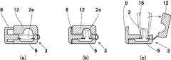
図3は、図2のA−A矢視を示す断面図であり、(a)はレンズ2がプリセットされた状態を示し、(b)はレンズ2が折り畳まれた後の状態を示している。また、(c)は折り畳んだレンズ2を鑷子15により取り出せる状態にしたものを示している。(a)に示すプリセット状態においては、レンズ2は自由移動できない程度に位置固定されているが、光学部2aに何ら余分な応力は付加されない。したがって、プリセット状態で長時間保管してもレンズ2の光学特性に悪影響を与えることがない。また、誤ってプランジャー4を操作したとしても、折り畳み部材8を押し込まない限りプランジャー4の動きは折り畳み部材8に衝突して規制されるので、(a)に示すプリセット状態では眼内レンズ2の押出しを防止することができる。さらに、ノズルキャップ11を外さない限り折り畳み部材8を押し込むこともできないので、誤って眼内レンズ2を折り畳むことも防止できる。3A and 3B are cross-sectional views taken along the line AA of FIG. 2, in which FIG. 3A shows a state where the
手術時、このインジェクター1を使用して眼内レンズ2を眼内へ挿入する場合、ノズルキャップ11を取り外した後、折り畳み部材8を押し込んでレンズ設置部5に収納された眼内レンズ2を変形させて折り畳む。具体的には、(b)に示すように折り畳み部材8を押し込むと、眼内レンズ2の光学部2aは本体3の内壁面と折り畳み部材8により圧縮され、略U字形状に折り畳まれる。その後、先端部たるノズル6を眼球の切開創口から眼球内に挿入し、プランジャー4により眼内レンズ2を押圧して眼内に移植することができる。なお、折り畳み部材8を押し込んで眼内レンズ2を折り畳んだ位置においては、折り畳み部材8に設けられたプランジャー通し穴8dの中心がプランジャー軸4aの軸心と一致するように構成されており、プランジャー4を押すことにより眼内レンズ2を押圧して移動することができるようになっている。When the
一方、術者の都合等によりインジェクター1を使用して直接眼内へレンズ2を移植するよりも、鑷子15により眼内レンズ2を把持して眼内に挿入する方が好ましい場合もある。そのような場合、(c)に示すように眼内レンズ2を折り畳み部材8によって折り畳んだ後、開閉蓋12を開いて折り畳んだ光学部2aを鑷子15により把持して眼内に挿入することができる。したがって、本発明によれば、インジェクター1を使用して眼内レンズ2を眼内に移植することができるとともに、眼内レンズ2を折り畳んだ後、必要に応じて鑷子15により眼内レンズ2を把持して眼内に移植することもできる。On the other hand, it may be preferable for the operator to hold the
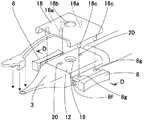
図4〜図8は、本発明に係る眼内レンズ挿入器具1の第2実施例を示すものであり、図4は開閉蓋12を開いた状態を示す図面である。本実施例は、折り畳み部材8、ノズルキャップ11および保護カバー16の具体的構造が前記第1実施例と異なる。したがって、第1実施例と共通する部分についての説明は省略し、異なる構造を有する折り畳み部材8、ノズルキャップ11および保護カバー16について説明する。4 to 8 show a second embodiment of the intraocular
本実施例による折り畳み部材8はレンズ設置部5において回転可能なボス8aが設けられ、そのボス8aにはレンズ設置部5に配置される押圧部8bと本体3から外方に伸びる操作部8cが一体的に設けられている。そして、図5に示すようにレンズ設置部5に眼内レンズ2をセットする際には、操作部8cを本体3より外方に回動させてレンズ設置部5に広いスペースを確保してレンズ2を設置する。この状態においてはボス8aに設けられた貫通溝8eの方向とプランジャー軸4aの方向が一致することはなく、誤操作等によりプランジャー4が押されたとしてもプランジャー軸4aの先端部4bはボス8aの側面に突き当たって移動が規制されるため、眼内レンズ2がプランジャー軸4aによって押圧されるのを防止することができる。The folding
また、本実施例によるノズルキャップ11は、図4に示すようにノズル6の先端部を塞ぐキャップ部11aとプレスホルダー11bが一体的に形成されている。ここで、プレスホルダー11bは本体3の外面と前記折り畳み部材8の操作部8cとの間に配置され、プレスホルダー11bを取外さない限り操作部8cの操作ができないよう機能する。Further, as shown in FIG. 4, the
さらに、図5に示すように、ノズル6およびレンズ設置部5全体を保護するための保護カバー16を設けることもできる。保護カバー16の下面には、2箇所に突起16aが一体的に設けられており、保護カバー16を本体3に装着すると、開閉蓋12に設けられた穴12aに前記突起16aが挿通され、レンズ2の光学部2aの外縁近傍に達するようにされている。したがって、保護カバー16を本体3に装着すると、レンズ設置部5におけるレンズ2の移動を規制することができる。なお、保護カバー16にもレンズ光学部2aの中心に対応する位置にレンズ2の状態を視認できるよう検査用の穴16bが設けられている。Furthermore, as shown in FIG. 5, a
図6は、図5のB−B矢視を示す断面図であり、レンズ設置部5にレンズ2がセットされた状態を示している。レンズ設置部5にレンズ2をセットする際には、折り畳み部材8の操作部8cを操作して押圧部8bを外方位置にすることにより、レンズ設置部5に光学部2aを載置できるスペースが確保される。もちろん、レンズ2をセットする場合には、保護カバー16を取り外し、開閉蓋12を開く必要がある。セットされた後のレンズ2は、保護カバー16に設けられた突起16aにより移動が制限される。FIG. 6 is a cross-sectional view taken along the line BB in FIG. 5 and shows a state where the
図7は、図5に対応する図面であり、折り畳み部材8の操作部8cが本体3側に操作されてレンズ2が折り畳まれる状態を示している。レンズ2を折り畳む際には、先ず保護カバー16を本体3から取り外す。そうすると、折り畳み部材8の操作部8cの動きを規制していたプレスホルダー11bも一緒に取り外され、レンズ2の折り畳み操作が可能な状態になる。そこで、折り畳み部材8の操作部8cを本体3側に押すと、折り畳み部材8はボス8aを中心として回動し、押圧部8bによりレンズ2の光学部2aの一端が押圧される。レンズ2の光学部2aの一端が押圧されれば、レンズ2は本体3の内壁と押圧部8bとの間に挟まれて圧縮されることから折り畳まれることになる。そして、折り畳み部材8のボス8aが回動すると、そのボス8aに設けられている貫通溝8eの方向とプランジャー軸4aの方向が一致するようにされている。このようにレンズ2が折り畳まれた後においては、プランジャー4の操作により折り畳まれたレンズ2の光学部2aを押圧して移動することができるようになる。したがって、プランジャー4を使用してレンズ2を眼内に移植する場合には、プランジャー4によりレンズ2の光学部2aを押圧して移植することができる。FIG. 7 is a drawing corresponding to FIG. 5 and shows a state in which the
図8は、図7中のC−C矢視断面を示すものであり、レンズ2折り畳み後の状態を示している。インジェクター1を使用して眼内レンズ2を移植する場合には、図8に示すレンズ2折り畳み後の状態からプランジャー4により光学部2aの外縁を押圧して移植する。一方、インジェクター1を使用せず、鑷子15によりレンズ2を把持して眼内にレンズ2を移植する場合には、図8に示す折り畳み後のレンズ2を、開閉蓋12を開けることによって鑷子15により把持して眼内に移植することができる(図15参照)。FIG. 8 shows a cross section taken along the line CC in FIG. 7 and shows a state after the
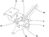
図9〜図12は、本発明に係る眼内レンズ挿入器具1の第3実施例を示すものであり、図9は保護カバー16を取り外した状態を示す図面である。本実施例は前記第1実施例や第2実施例とは折り畳み部材8および開閉蓋12の構造が大きく異なるが、その他の構造については共通している。したがって、第1実施例や第2実施例と共通する部分についての説明は省略し、異なる構造を有する折り畳み部材8と開閉蓋12について説明する。9 to 12 show a third embodiment of the intraocular
本実施例においては2つの折り畳み部材8を有し、レンズ2の光学部2aを両側から挟んで折り畳むようになっている。また、2つの折り畳み部材8はレンズ設置部5に対して軸対称位置に配置され、板バネ17により連結されている。さらに折り畳み部材8の適所には突起8fが設けられ、この突起8fが本体3に設けられた凹所等に係止できる構成とされている。かかる構造を有するインジェクター1において、レンズ設置部5にレンズ2をセットする際には板バネ17を圧縮することなく、折り畳み部材8を外方に出した状態にしておく。この状態においては2つの折り畳み部材8,8間にレンズ2を収納できるスペースが確保される。In this embodiment, two
レンズ2をセット後、図10に示すように本体3に保護カバー16が装着される。このことによりレンズ2の位置は固定されるとともに、ロック機構8g,16cによって2つの折り畳み部材8,8の動きも規制される。すなわち、保護カバー16の裏面にはレンズ2の位置を固定するための2箇所の突起16aと、折り畳み部材8の動きを固定するための4箇所の突起16cが設けられており、保護カバー16を本体3に装着することによりレンズ2の動きと折り畳み部材8の動きをロックすることができるようにされている。具体的には、保護カバー16の裏面に設けられた2箇所の突起16aは、開閉蓋12に設けられた2箇所の穴20に挿通され、レンズ2の光学部2aの移動を規制する。また、折り畳み部材8に設けられたロック穴8gに保護カバー16の突起16cが挿入されることにより折り畳み部材8はロックされることになる。After the
なお、図10に示す開閉蓋12は、本体3とは別体として構成しているが、ヒンジ等により本体3と一体構造とすることもできる。Although the opening / closing
図11は図10のD−D矢視を示す斜視図であり、(a)はプリセット状態を示し、(b)はレンズ折り畳み後の状態を示している。(a)に示すプリセット状態においては、レンズ2の光学部2aにストレスを与えることなく載置される。(b)に示すレンズ折り畳み後の状態では、レンズ2の光学部2aは両側から押されて断面が略U字形に折り畳まれている。ここで、レンズ設置部5の上部に装着される開閉蓋12には、レンズ2の状態を視認するための検査穴19と保護カバー16の突起16aが挿通される穴20が設けられている。11A and 11B are perspective views showing a DD arrow in FIG. 10, in which FIG. 11A shows a preset state, and FIG. 11B shows a state after the lens is folded. In the preset state shown in (a), the
図12は、図11と同じ部位を示す図面であるが、レンズ折り畳み後のレンズ2の移植方法を説明するためのものである。具体的には、図10のD−D矢視を示す斜視図であり、(a)はプランジャー軸4aによりレンズ2を押し出す場合を示し、(b)は鑷子15によりレンズ2を把持する場合を示している。インジェクター1を使用してレンズ2を移植する場合には、(a)に示すように2つの折り畳み部材8を両側から押してレンズ2を折り畳んだ後、プランジャー軸4aによりレンズ2を押圧して移植する。一方、インジェクター1を使用せずに鑷子15によりレンズ2を把持して移植する場合には、(b)に示すようにレンズ折り畳み後に開閉蓋12を取外し、その後、鑷子15により折り畳んだレンズ2を把持して眼内に移植することができる(図15参照)。FIG. 12 is a view showing the same portion as FIG. 11, but is for explaining a method of transplanting the
図13および図14は、本発明に係る眼内レンズ挿入器具1の第4実施例を示すものであり、開閉蓋12を取外した状態を示している。本実施例は前記第3実施例と同様の構成を有するものであるが、折り畳み部材8の具体的構造が第3実施例と異なる。したがって、第3実施例と共通する部分についての説明は省略し、第3実施例と異なる構造を有する折り畳み部材8について説明する。13 and 14 show a fourth embodiment of the intraocular
本実施例は、レンズ設置部5に2つの折り畳み部材8を設け、前記2つの折り畳み部材8を板バネ17により連結すると共に、前記折り畳み部材8に突起8fを設けて本体3の適所に係止し、前記板バネ17の付勢力に抗して前記折り畳み部材8の位置を保持可能としたものである。ただし、板バネ17による連結方法が第3実施例と異なっている。2つの折り畳み部材8は略八の字状に配置され、その一端を板バネ17により連結している。そして、板バネ17を中心にして2つの折り畳み部材8が所定角度だけ回動できるようにされている。すなわち、2つの折り畳み部材8を外方に開いた状態ではレンズ設置部5において、2つの折り畳み部材8は略八の字状に配置され、レンズ光学部2aを設置できるだけのスペースが確保される。したがって、この状態においてはレンズ光学部2aに余分な応力を与えることなくレンズ2を設置できる。レンズ設置後、開閉蓋12を本体3に装着することによりレンズ2のセットは完了する。また、開閉蓋12の裏面には図示しないが、レンズ2の位置を固定するための複数の突起と折り畳み部材8の動きを固定するための複数の突起が設けられており、開閉蓋12を本体3に装着することによりレンズ2の動きと折り畳み部材8の動きを規制することができるようになっている。さらに、開閉蓋12にはプランジャー軸4aの動きを規制する突き当てを設け、プランジャー4の誤操作によってレンズ2が押圧されないようにされている。In this embodiment, two
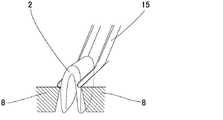
図15は、インジェクター1を使用することなく、鑷子15によりレンズ2を把持する様子を示すものである。レンズ2が折り畳まれた後においては、レンズ2の折り曲げ部が折り畳み部材8よりも上方に凸となるので、鑷子15により容易にレンズ2を把持することができる。FIG. 15 shows a state in which the
以上、本発明を幾つかの実施例に基づいて説明したが、本発明は上記した実施例に限定されるものではなく、種々の変形実施をすることができる。例えば、上記実施例においては、2つの折り畳み部材8を連結する方法として別体の板バネ17を用いる場合を示したが、2つの折り畳み部材8とバネ部材を一体に形成することもできる。As mentioned above, although this invention was demonstrated based on some Examples, this invention is not limited to an above-described Example, Various deformation | transformation implementation can be performed. For example, in the above-described embodiment, the case where the
1 眼内レンズ挿入器具(インジェクター)
2 眼内レンズ(レンズ)
3 本体
4 プランジャー
5 レンズ設置部
8 折り畳み部材
8f 突起
12 開閉蓋
14 ヒンジ
15 鑷子
8g,16c ロック機構
17 板バネ1 Intraocular lens insertion device (injector)
2 Intraocular lens (lens)
3
8f protrusion
12 Opening / closing lid
14 Hinge
15 Choshi
8g, 16c lock mechanism
17 leaf spring
Claims (7)
Translated fromJapaneseThe intraocular lens according to any one of claims 1 to 5, wherein the folding member is provided with a locking mechanism, and the intraocular lens cannot be folded unless the locking mechanism is released. Insertion instrument.
Priority Applications (6)
| Application Number | Priority Date | Filing Date | Title |
|---|---|---|---|
| JP2005049700AJP4836046B2 (en) | 2005-02-24 | 2005-02-24 | Intraocular lens insertion device |
| EP06711614.5AEP1857074B1 (en) | 2005-02-24 | 2006-01-12 | Intraocular lens inserting instrument |
| CN2006800050112ACN101119686B (en) | 2005-02-24 | 2006-01-12 | Intraocular lens insertion device |
| US11/816,676US8523877B2 (en) | 2005-02-24 | 2006-01-12 | Intraocular lens inserting instrument |
| PCT/JP2006/300291WO2006090531A1 (en) | 2005-02-24 | 2006-01-12 | Intraocular lens inserting instrument |
| US13/966,209US9364320B2 (en) | 2005-02-24 | 2013-08-13 | Intraocular lens inserting instrument |
Applications Claiming Priority (1)
| Application Number | Priority Date | Filing Date | Title |
|---|---|---|---|
| JP2005049700AJP4836046B2 (en) | 2005-02-24 | 2005-02-24 | Intraocular lens insertion device |
Related Child Applications (1)
| Application Number | Title | Priority Date | Filing Date |
|---|---|---|---|
| JP2011022324ADivisionJP5136966B2 (en) | 2011-02-04 | 2011-02-04 | Intraocular lens insertion device |
Publications (2)
| Publication Number | Publication Date |
|---|---|
| JP2006230707A JP2006230707A (en) | 2006-09-07 |
| JP4836046B2true JP4836046B2 (en) | 2011-12-14 |
Family
ID=36927179
Family Applications (1)
| Application Number | Title | Priority Date | Filing Date |
|---|---|---|---|
| JP2005049700AExpired - LifetimeJP4836046B2 (en) | 2005-02-24 | 2005-02-24 | Intraocular lens insertion device |
Country Status (5)
| Country | Link |
|---|---|
| US (2) | US8523877B2 (en) |
| EP (1) | EP1857074B1 (en) |
| JP (1) | JP4836046B2 (en) |
| CN (1) | CN101119686B (en) |
| WO (1) | WO2006090531A1 (en) |
Families Citing this family (58)
| Publication number | Priority date | Publication date | Assignee | Title |
|---|---|---|---|---|
| EP1832247B1 (en) | 2004-12-27 | 2015-06-24 | Hoya Corporation | Intraocular lens implanting device |
| EP1849436B1 (en) | 2005-01-26 | 2017-11-01 | Hoya Corporation | Intraocular lens insertion device |
| JP4836046B2 (en) | 2005-02-24 | 2011-12-14 | Hoya株式会社 | Intraocular lens insertion device |
| US8574239B2 (en) | 2005-09-28 | 2013-11-05 | Hoya Corporation | Intraocular lens insertion device |
| JP4520390B2 (en) | 2005-09-29 | 2010-08-04 | 株式会社ニデック | Intraocular lens insertion system |
| JP4877643B2 (en) | 2005-12-08 | 2012-02-15 | Hoya株式会社 | Intraocular lens insertion device |
| JP4908977B2 (en)* | 2006-09-05 | 2012-04-04 | 興和株式会社 | Intraocular lens insertion device |
| US8435288B2 (en)* | 2006-09-22 | 2013-05-07 | Lenstec Barbados Inc. | System and method for storing, shipping and injecting ocular devices |
| US8475528B2 (en) | 2007-05-30 | 2013-07-02 | Hoya Corporation | Intraocular lens insertion device |
| JP5236638B2 (en) | 2007-05-30 | 2013-07-17 | Hoya株式会社 | Intraocular lens insertion device |
| JP5086713B2 (en) | 2007-07-11 | 2012-11-28 | Hoya株式会社 | Intraocular lens insertion device |
| JP5189356B2 (en)* | 2007-12-28 | 2013-04-24 | 興和株式会社 | Intraocular lens insertion device |
| JP5255832B2 (en) | 2007-12-28 | 2013-08-07 | 興和株式会社 | Intraocular lens insertion device |
| JP5254669B2 (en) | 2008-06-05 | 2013-08-07 | Hoya株式会社 | Intraocular lens insertion device and cartridge |
| JP5470753B2 (en)* | 2008-06-17 | 2014-04-16 | Hoya株式会社 | Intraocular lens insertion device |
| JP5323420B2 (en) | 2008-08-21 | 2013-10-23 | Hoya株式会社 | Intraocular lens insertion device |
| JP5416379B2 (en) | 2008-09-04 | 2014-02-12 | Hoya株式会社 | Intraocular lens insertion device |
| FR2935606B1 (en)* | 2008-09-11 | 2010-09-03 | Patrick Meunier | INTRAOCULAR LENS INJECTION SYSTEM COMPRISING AN INJECTOR WITH A CARTRIDGE AND A LOADING DEVICE |
| SG172876A1 (en) | 2009-01-07 | 2011-08-29 | Hoya Corp | Intraocular lens insertion device |
| GB2470416A (en)* | 2009-05-22 | 2010-11-24 | Rayner Intraocular Lenses Ltd | Intraocular Lens Cartridge |
| JP5627861B2 (en)* | 2009-05-29 | 2014-11-19 | 株式会社ニデック | Intraocular lens insertion device |
| JP5507282B2 (en)* | 2010-02-05 | 2014-05-28 | Hoya株式会社 | Intraocular lens insertion device |
| US20110245840A1 (en)* | 2010-03-31 | 2011-10-06 | Seyboth William J | Intraocular lens injector system |
| JP5735531B2 (en) | 2010-04-08 | 2015-06-17 | Hoya株式会社 | Ocular graft insertion device |
| JP5511530B2 (en) | 2010-06-10 | 2014-06-04 | Hoya株式会社 | Intraocular lens insertion device |
| KR101179976B1 (en) | 2010-06-16 | 2012-09-07 | 주식회사 알이티 | Injector for disposable intraocular lens |
| KR101161356B1 (en) | 2010-11-12 | 2012-06-29 | 주식회사 알이티 | Preloaded iol injector |
| DE102011101940B4 (en) | 2011-05-18 | 2014-01-02 | Iolution Gmbh | Injector for implanting an intraocular lens |
| CN102283741A (en)* | 2011-07-14 | 2011-12-21 | 广州卫视博生物科技有限公司 | Folding artificial vitreous body injector |
| US20130060256A1 (en)* | 2011-09-06 | 2013-03-07 | Myoung Soo Han | Flat-type integral preloaded injector with intraocular lens fixing device |
| US20130130222A1 (en)* | 2011-11-21 | 2013-05-23 | Alessandro RUZZA | Device, kit and method for use in ophthalmology |
| US9295248B2 (en) | 2011-11-21 | 2016-03-29 | Fondazione Banca Degli Occhi Del Veneto Onlus | Device, kit and methods for use in ophthalmology |
| ES2610198T3 (en) | 2012-06-04 | 2017-04-26 | Alcon Pharmaceuticals Ltd. | Intraocular lens insertion device and method for unloading an intraocular lens from a cartridge |
| CN108420598B (en) | 2012-06-12 | 2021-03-09 | 爱尔康公司 | Hand-held gas mixer and injector assembly, hand-held gas injector device and method of mixing gas |
| US9237947B2 (en) | 2012-11-09 | 2016-01-19 | Bausch & Lomb Incorporated | Hingeless cartridge for intraocular lens injector providing haptic control |
| US9155615B2 (en)* | 2012-11-09 | 2015-10-13 | Bausch & Lomb Incorporated | Hingeless cartridge for use with an intraocular lens injector providing haptic control |
| DE102012223885B4 (en)* | 2012-12-20 | 2022-01-05 | Humanoptics Ag | Intraocular lens storage system, transfer arrangement and method for transferring an intraocular lens to an injection device |
| AU2014226115B2 (en)* | 2013-03-05 | 2018-08-02 | Johnson & Johnson Surgical Vision, Inc. | Automated preloaded intraocular lens injector |
| JP5545606B2 (en)* | 2013-04-18 | 2014-07-09 | Hoya株式会社 | Intraocular lens insertion device and cartridge |
| EP2873391A1 (en)* | 2013-11-15 | 2015-05-20 | Atttinger Technik AG | Intraocular lens injector, method for folding an intraocular lens and intraocular lens injector system |
| BR102014006114B1 (en)* | 2014-03-14 | 2022-05-10 | Antônio Francisco Neves Filho | Mechanical or biological heart valve stent for minimally invasive valve replacement procedure and stent delivery device |
| JP6599889B2 (en) | 2014-04-04 | 2019-10-30 | アルコン ファーマシューティカルズ リミティド | Intraocular lens inserter |
| DE102014005719A1 (en)* | 2014-04-22 | 2015-10-22 | Iolution Gmbh | Container system for storing an intraocular lens |
| US9636217B2 (en)* | 2014-05-08 | 2017-05-02 | Novartis Ag | Equipment and methods used in folding and implanting foldable lenses in the eye |
| JP6646987B2 (en) | 2015-09-16 | 2020-02-14 | Hoya株式会社 | Intraocular lens insertion device |
| EP3351212B2 (en) | 2015-09-16 | 2023-08-23 | HOYA Corporation | Intraocular lens insertion tool |
| US10172706B2 (en) | 2015-10-31 | 2019-01-08 | Novartis Ag | Intraocular lens inserter |
| US10722347B2 (en)* | 2015-12-17 | 2020-07-28 | Atrion Medical Products, Inc. | Intraocular lens delivery device and method of use |
| US11547555B2 (en) | 2015-12-17 | 2023-01-10 | Atrion Medical Products, Inc. | Intraocular lens delivery device and method of use |
| JP6929843B2 (en) | 2016-06-28 | 2021-09-01 | Hoya株式会社 | Intraocular lens inserter |
| EP3476374B1 (en) | 2016-06-28 | 2025-01-08 | Hoya Corporation | Intraocular lens insertion tool |
| US11000367B2 (en) | 2017-01-13 | 2021-05-11 | Alcon Inc. | Intraocular lens injector |
| JP7162443B2 (en) | 2018-05-16 | 2022-10-28 | Hoya株式会社 | intraocular ring inserter with container |
| JP7162445B2 (en) | 2018-05-25 | 2022-10-28 | Hoya株式会社 | intraocular lens inserter |
| US11224537B2 (en) | 2018-10-19 | 2022-01-18 | Alcon Inc. | Intraocular gas injector |
| US11337797B2 (en)* | 2018-12-19 | 2022-05-24 | Alcon Inc. | Cam actuated base folding mechanism |
| CN113226221B (en)* | 2018-12-20 | 2024-11-12 | 爱尔康公司 | Hook optics management system using edge folder |
| WO2025029231A1 (en)* | 2023-07-31 | 2025-02-06 | Vsy Biyoteknoloji Ve Ilac Sanayi Anonim Sirketi | A novel cartridge injection system comprising a top push button for intraocular lenses |
Family Cites Families (214)
| Publication number | Priority date | Publication date | Assignee | Title |
|---|---|---|---|---|
| US577266A (en)* | 1897-02-16 | Pneumatic door-check | ||
| US2761446A (en) | 1955-03-30 | 1956-09-04 | Chemical Specialties Co Inc | Implanter and cartridge |
| US4205747A (en)* | 1978-09-05 | 1980-06-03 | Cilco, Inc. | Lens storage device |
| US4269307A (en)* | 1979-08-09 | 1981-05-26 | Iolab Corporation | Intraocular lens storage assembly |
| US4423809A (en)* | 1982-02-05 | 1984-01-03 | Staar Surgical Company, Inc. | Packaging system for intraocular lens structures |
| US4702244A (en) | 1982-02-05 | 1987-10-27 | Staar Surgical Company | Surgical device for implantation of a deformable intraocular lens |
| US4573998A (en)* | 1982-02-05 | 1986-03-04 | Staar Surgical Co. | Methods for implantation of deformable intraocular lenses |
| US4608049A (en) | 1982-06-28 | 1986-08-26 | Kelman Charles D | Intraocular lens and method of inserting an intraocular lens into an eye |
| US4634423A (en)* | 1984-04-30 | 1987-01-06 | Bailey Jr Paul F | Ophthalmological method and instrument for implantation of posterior chamber intraocular lens |
| US4787904A (en) | 1984-07-06 | 1988-11-29 | Severin Sanford L | Hydrophillic intraocular lens |
| US4699140A (en) | 1985-07-10 | 1987-10-13 | Iolab Corporation | Instrument for inserting an intraocular lens |
| US4681102A (en) | 1985-09-11 | 1987-07-21 | Bartell Michael T | Apparatus and method for insertion of an intra-ocular lens |
| US4715373A (en) | 1985-09-27 | 1987-12-29 | Mazzocco Thomas R | Devices for implantation of deformable intraocular lens structures |
| US4750498A (en)* | 1986-02-21 | 1988-06-14 | Coopervision, Inc. | Method and tool for inserting an intraocular lens |
| DE3610925C2 (en) | 1986-03-24 | 1994-11-03 | Michael Ulrich Prof D Dardenne | Device for folding an implantable intraocular lens, in particular provided with two plastic haptic plates on the side, and for inserting the folded intraocular lens into the eye |
| US4697697A (en) | 1986-08-18 | 1987-10-06 | Coopervision, Inc. | Method and apparatus for packaging an intraocular lens |
| JPS63197453A (en) | 1986-11-07 | 1988-08-16 | ザ・クーパー・カンパニー・インク | Instrument and method for inserting compressive intraocular lens |
| US4919130A (en)* | 1986-11-07 | 1990-04-24 | Nestle S.A. | Tool for inserting compressible intraocular lenses into the eye and method |
| US4747404A (en)* | 1986-11-10 | 1988-05-31 | Kresge Eye Institute Of Wayne State University | Foldable intraocular lens inserter |
| US4763650A (en) | 1987-01-20 | 1988-08-16 | Hauser Stephen G | Instrument for inserting a deformable lens into the eye |
| US4810249A (en) | 1987-03-12 | 1989-03-07 | Habley Medical Technology Corp. | Linear and Vernier-type syringe |
| US4994028A (en)* | 1987-03-18 | 1991-02-19 | Endocon, Inc. | Injector for inplanting multiple pellet medicaments |
| US4819631A (en)* | 1987-03-26 | 1989-04-11 | Poley Brooks J | Folded intraocular lens, method of implanting it, retainer, and apparatus for folding lens |
| US5176686A (en)* | 1987-03-26 | 1993-01-05 | Poley Brooks J | Apparatus for packaging, folding, rigidifying and inserting an intraocular lens |
| US4769034A (en) | 1987-03-26 | 1988-09-06 | Poley Brooks J | Folded intraocular lens, method of implanting folded intraocular lens |
| US4988352A (en) | 1987-03-26 | 1991-01-29 | Poley Brooks J | Method and apparatus for folding, freezing and implanting intraocular lens |
| US4781719A (en) | 1987-07-28 | 1988-11-01 | Kelman Charles D | Method of inserting an intraocular lens into an eye |
| US4759359A (en) | 1987-08-31 | 1988-07-26 | Allergan, Inc. | Lens implantation instrument |
| US4834094A (en)* | 1987-10-07 | 1989-05-30 | Patton Medical Technologies, Inc. | "Canoe" apparatus for inserting intra-ocular lens into the eye |
| US4765329A (en) | 1987-10-19 | 1988-08-23 | Cumming, Redwitz & Wilson, Inc. | Intraocular lens insertion instrument |
| US4934363A (en)* | 1987-12-15 | 1990-06-19 | Iolab Corporation | Lens insertion instrument |
| US4880000A (en) | 1987-12-15 | 1989-11-14 | Iolab Corporation | Lens insertion instrument |
| US4836201A (en)* | 1988-03-24 | 1989-06-06 | Patton Medical Technologies, Inc. | "Envelope" apparatus for inserting intra-ocular lens into the eye |
| US4862885A (en) | 1988-05-25 | 1989-09-05 | Cumming J Stuart | Instrument for inserting a deformable intraocular lens into the eye |
| JPH02156943A (en) | 1988-10-07 | 1990-06-15 | Ioptex Res Inc | Lens inserting means in eye |
| US5066297A (en)* | 1989-01-23 | 1991-11-19 | Cumming J Stuart | Intraocular lens insertion device |
| US4976716A (en) | 1989-01-23 | 1990-12-11 | Cumming J Stuart | Intraocular lens insertion device |
| US4955889A (en) | 1989-02-06 | 1990-09-11 | Allergan, Inc. | Apparatus for inserting a lens into an eye and method for using same |
| US5222972A (en)* | 1989-04-12 | 1993-06-29 | Allergan, Inc. | Small incision intraocular lens insertion apparatus |
| US5098439A (en)* | 1989-04-12 | 1992-03-24 | Allergan, Inc. | Small incision intraocular lens insertion apparatus |
| US5171241A (en) | 1989-06-09 | 1992-12-15 | Ioptex Research Inc. | Device for folding an intraocular lens and holding it in the folded state |
| DE4030492C1 (en) | 1990-09-26 | 1991-09-05 | Adatomed Pharmazeutische Und Medizintechnische Gesellschaft Mbh, 8000 Muenchen, De | |
| DE4039119C1 (en) | 1990-12-07 | 1991-09-05 | Dieter Dr.Med. 8904 Friedberg De Klaas | |
| DE4108303C2 (en)* | 1991-03-14 | 1993-11-04 | Adatomed Pharma & Med | METHOD AND DEVICE FOR INSERTING A RUBBER-ELASTIC INTRAOCULAR LENS IN AN IMPLANTATION TOOL |
| DE4110278A1 (en) | 1991-03-28 | 1992-10-01 | Geuder Hans Gmbh | Surgical instrument for implanting soft lenses in eye - has guide sleeve attached to handle by quick-action coupling |
| US5123905A (en)* | 1991-06-07 | 1992-06-23 | Kelman Charles D | Intraocular lens injector |
| JPH0779825B2 (en) | 1991-06-13 | 1995-08-30 | キヤノンスター株式会社 | Intraocular lens implanter |
| JPH0779826B2 (en) | 1991-06-14 | 1995-08-30 | キヤノンスター株式会社 | Intraocular lens implanter |
| US5259395A (en) | 1992-01-15 | 1993-11-09 | Siemens Pacesetter, Inc. | Pacemaker lead with extendable retractable lockable fixing helix |
| US5190552A (en)* | 1992-02-04 | 1993-03-02 | Kelman Charles D | Slotted tube injector for an intraocular lens |
| US5395378A (en)* | 1992-05-18 | 1995-03-07 | Henry H. McDonald | Eye implantable lens haptics insertion and twist apparatus |
| US5571113A (en) | 1992-05-18 | 1996-11-05 | Henry H. McDonald | Surgical probe with tips for plastic lens implantation in the eye |
| US5242450A (en) | 1992-05-18 | 1993-09-07 | Henry H. McDonald | Eye implantable lens haptics twist apparatus |
| US5304182A (en)* | 1992-09-23 | 1994-04-19 | Kabi Pharmacia Ophthalmics, Inc. | Apparatus and method for curling and inserting flexible intraocular lenses |
| US5728102A (en)* | 1992-09-30 | 1998-03-17 | Staar Surgical Company, Inc. | Disposable intraocular lens insertion system |
| US5902307A (en)* | 1992-09-30 | 1999-05-11 | Starr Surgical Company, Inc. | Method of loading an intraocular lens into a lens injecting apparatus, and implanting the intraocular lens through a small incision made in an eye |
| US5860984A (en)* | 1992-09-30 | 1999-01-19 | Staar Surgical Company, Inc. | Spring biased deformable intraocular injecting apparatus |
| US6001107A (en) | 1992-09-30 | 1999-12-14 | Staar Surgical Company, Inc. | Deformable intraocular lens injecting apparatus |
| US5620450A (en)* | 1992-09-30 | 1997-04-15 | Staar Surgical Company, Inc. | Transverse hinged deformable intraocular lens injecting apparatus |
| US6712848B1 (en)* | 1992-09-30 | 2004-03-30 | Staar Surgical Company, Inc. | Deformable intraocular lens injecting apparatus with transverse hinged lens cartridge |
| US5499987A (en)* | 1992-09-30 | 1996-03-19 | Staar Surgical Company | Deformable intraocular lens cartridge |
| US5772666A (en) | 1992-09-30 | 1998-06-30 | Staar Surgical Company, Inc. | Deformable intraocular lens injecting apparatus with deformable tip plunger |
| US5928245A (en) | 1992-09-30 | 1999-07-27 | Staar Surgical Company, Inc. | Deformable intraocular lens injecting apparatus with transverse hinged lens cartridge |
| US6506195B2 (en)* | 1992-09-30 | 2003-01-14 | Staar Surgical Company, Inc. | Deformable intraocular lens insertion system |
| US6056757A (en) | 1992-09-30 | 2000-05-02 | Staar Surgical Company, Inc. | Implantation device with deformable nozzle tip for implanting a deformable intraocular lens |
| US5616148A (en)* | 1992-09-30 | 1997-04-01 | Staar Surgical Company, Inc. | Transverse hinged deformable intraocular lens injecting apparatus |
| US5941886A (en) | 1992-09-30 | 1999-08-24 | Staar Surgical Company, Inc. | Hingeless lens cartridges for insertion of deformable intraocular lens |
| US6022358A (en) | 1992-09-30 | 2000-02-08 | Staar Surgical Company, Inc. | Deformable intraocular lens injecting device |
| DE69331807T2 (en) | 1992-09-30 | 2002-09-26 | Vladimir Feingold | INTRAOCULAR LENS INSERTION SYSTEM |
| US6059791A (en)* | 1992-09-30 | 2000-05-09 | Staar Surgical Company, Inc. | Deformable intraocular lens injection system, and method thereof |
| US5876440A (en)* | 1992-09-30 | 1999-03-02 | Staar Surgical Company, Inc. | Methods of implantation of deformable intraocular lens |
| US5807400A (en) | 1992-09-30 | 1998-09-15 | Staar Surgical Company, Inc. | Deformable intraocular lens insertion system |
| US5281227A (en)* | 1992-11-09 | 1994-01-25 | Allergan, Inc. | Lens case with IOL folding device |
| US5275604A (en)* | 1992-12-03 | 1994-01-04 | Kabi Pharmacia Ophthalmics, Inc. | Contoured duct apparatus and method for insertion of flexible intraocular lens |
| US5653715A (en) | 1993-03-09 | 1997-08-05 | Chiron Vision Corporation | Apparatus for preparing an intraocular lens for insertion |
| US5468246A (en) | 1993-07-02 | 1995-11-21 | Iovision, Inc. | Intraocular lens injector |
| US5425734A (en) | 1993-07-02 | 1995-06-20 | Iovision, Inc. | Intraocular lens injector |
| JP3459664B2 (en)* | 1993-07-15 | 2003-10-20 | キヤノンスター株式会社 | Deformable intraocular lens insertion device |
| SE9303568D0 (en) | 1993-10-29 | 1993-10-29 | Kabi Pharmacia Ab | Improvements in injection devices |
| US5582613A (en) | 1993-11-18 | 1996-12-10 | Allergan | Apparatus and methods for controlled insertion of intraocular lenses |
| US5584304A (en) | 1993-11-18 | 1996-12-17 | Allergan, Inc. | Method of inserting an IOL using a forceps inside a folding tube |
| US5702402A (en) | 1994-04-29 | 1997-12-30 | Allergal | Method and apparatus for folding of intraocular lens |
| WO1995013766A1 (en) | 1993-11-18 | 1995-05-26 | Allergan, Inc. | Deformable lens insertion apparatus |
| AU1915595A (en) | 1994-02-09 | 1995-08-29 | Kabi Pharmacia Ophthalmics, Inc. | Rapid implantation of shape transformable optical lenses |
| US6174315B1 (en)* | 1994-02-15 | 2001-01-16 | Staar Surgical Company, Inc. | Spring biased deformable intraocular injecting apparatus |
| US5578042A (en) | 1994-03-14 | 1996-11-26 | Cumming; J. Stuart | Ophthalmic kit and method for lens insertion |
| US5645534A (en) | 1994-06-24 | 1997-07-08 | Becton Dickinson And Company | Time of last injection indicator for medication delivery pen |
| JP3412106B2 (en) | 1994-07-07 | 2003-06-03 | キヤノンスター株式会社 | Deformable intraocular lens insertion device |
| JP3412107B2 (en) | 1994-07-18 | 2003-06-03 | キヤノンスター株式会社 | Deformable intraocular lens insertion device |
| US5454818A (en) | 1994-07-26 | 1995-10-03 | Alcon Laboratories, Inc. | Intraocular lens folder |
| JP3937181B2 (en)* | 1994-08-05 | 2007-06-27 | ボシュ・アンド・ロム・インコーポレイテッド | Device for inserting a flexible intraocular lens |
| CN1143313A (en) | 1994-11-18 | 1997-02-19 | 弗拉基米尔·法因戈尔德 | Disposable intraocular lens insertion system |
| US5803925A (en) | 1995-01-17 | 1998-09-08 | Allergan | IOL insertion apparatus with covalently bonded lubricant |
| EP0957848A4 (en) | 1995-03-14 | 2001-05-02 | Staar Surgical Co | Deformable intraocular lens injecting device |
| US5643276A (en) | 1995-10-10 | 1997-07-01 | Allergan | Apparatus and method for providing desired rotational orientation to an intraocular lens |
| US5735858A (en) | 1996-01-26 | 1998-04-07 | Allergan | IOL insertion apparatus and method for using same |
| US5776138A (en)* | 1996-01-26 | 1998-07-07 | Allergan | Apparatus and methods for IOL insertion |
| FR2749752B1 (en)* | 1996-06-17 | 1998-11-20 | Moria Sa | DEVICE FOR FOLDING AND HOLDING A FLEXIBLE INTRAOCULAR IMPLANT |
| US6083230A (en)* | 1997-07-30 | 2000-07-04 | Allergan | Method for making IOL insertion apparatus |
| US5716364A (en) | 1996-07-10 | 1998-02-10 | Allergan | IOL insertion apparatus and method for making and using same |
| US6283975B1 (en) | 1996-07-10 | 2001-09-04 | Allergan Sales, Inc. | IOL insertion apparatus and method for making and using same |
| US5766181A (en) | 1996-08-02 | 1998-06-16 | Staar Surgical Company, Inc. | Spring biased deformable intraocular injecting apparatus |
| US5876406A (en) | 1996-08-02 | 1999-03-02 | Staar Surgical Company, Inc. | Deformable intraocular lens injecting apparatus with transverse hinged lens cartridge |
| US5944725A (en) | 1996-09-26 | 1999-08-31 | Bausch & Lomb Surgical, Inc. | Method and apparatus for inserting a flexible membrane into an eye |
| US5810834A (en) | 1996-10-07 | 1998-09-22 | Chiron Vision Corporation | Tip formation for inserting a flexible membrane into an eye |
| JP3226813B2 (en)* | 1996-12-13 | 2001-11-05 | トリンプ・インターナショナル・ジャパン株式会社 | Women's clothing |
| US5947975A (en)* | 1997-03-07 | 1999-09-07 | Canon Staar Co., Inc. | Inserting device for deformable intraocular lens |
| US5919197A (en) | 1997-05-05 | 1999-07-06 | Surgical Concepts, Inc. | Insertion of multiple folded lens into the eye |
| US5921966A (en) | 1997-08-11 | 1999-07-13 | Becton Dickinson And Company | Medication delivery pen having an improved clutch assembly |
| JP3779819B2 (en) | 1997-08-11 | 2006-05-31 | キヤノンスター株式会社 | Lens insertion device for intraocular insertion |
| US5947974A (en) | 1997-12-09 | 1999-09-07 | Allergan | Folding device and method for an intraocular lens |
| US5921989A (en) | 1998-02-12 | 1999-07-13 | Allergan | Lens protector for intraocular lens inserter |
| US6193193B1 (en)* | 1998-04-01 | 2001-02-27 | Trw Inc. | Evolvable propulsion module |
| US6497708B1 (en) | 1998-05-11 | 2002-12-24 | Medevec Licensing, B.V. | Intraocular lens insertion instrument |
| US6371960B2 (en) | 1998-05-19 | 2002-04-16 | Bausch & Lomb Surgical, Inc. | Device for inserting a flexible intraocular lens |
| US6010510A (en) | 1998-06-02 | 2000-01-04 | Alcon Laboratories, Inc. | Plunger |
| US6143001A (en) | 1998-06-02 | 2000-11-07 | Alcon Laboratories, Inc. | Asymmetric intraocular lens injection cartridge |
| US6447520B1 (en) | 2001-03-19 | 2002-09-10 | Advanced Medical Optics, Inc. | IOL insertion apparatus with IOL engagement structure and method for using same |
| DE19904220C2 (en) | 1999-02-03 | 2001-08-30 | Helmut Binder | Injector for folding and inserting an intraocular lens, and containers for storing and transporting the injector |
| FR2789890B1 (en) | 1999-02-22 | 2002-01-18 | Lab Contactologie Appl Lca | DEVICE FOR INJECTING AN INTRAOCULAR LENS IN FLEXIBLE MATERIAL |
| US6129733A (en) | 1999-04-15 | 2000-10-10 | Allergan Sales, Inc. | Apparatus for holding intraocular lenses and injectors, and methods for using same |
| US6386357B1 (en)* | 1999-07-12 | 2002-05-14 | Hoya Healthcare Corporation | Soft intraocular lens-folding device and storage case |
| US6248111B1 (en) | 1999-08-06 | 2001-06-19 | Allergan Sales, Inc. | IOL insertion apparatus and methods for using same |
| US6699285B2 (en) | 1999-09-24 | 2004-03-02 | Scieran Technologies, Inc. | Eye endoplant for the reattachment of a retina |
| JP3728155B2 (en) | 1999-10-05 | 2005-12-21 | キヤノンスター株式会社 | Intraocular lens insertion system |
| JP3944555B2 (en) | 1999-10-06 | 2007-07-11 | キヤノンスター株式会社 | Intraocular lens insertion system |
| US6312433B1 (en) | 1999-10-22 | 2001-11-06 | Staar Surgical Company, Inc. | Deformable intraocular lens injecting apparatus and method |
| US6387101B1 (en)* | 1999-10-22 | 2002-05-14 | Staar Surgical Company, Inc. | Deformable intraocular lens injecting apparatus and method |
| US6251114B1 (en) | 1999-10-29 | 2001-06-26 | Allergan Sales, Inc. | Rotatable IOL insertion apparatus and method for using same |
| SE9904338D0 (en)* | 1999-11-30 | 1999-11-30 | Pharmacia & Upjohn Ab | Intraocular lens implants |
| US6283976B1 (en) | 2000-05-05 | 2001-09-04 | Allergan Sales Inc. | Intraocular lens implanting instrument |
| GB0011507D0 (en) | 2000-05-13 | 2000-06-28 | Duckworth & Kent Ltd | Ophthalmic lens injectors |
| FR2814360B1 (en) | 2000-09-28 | 2002-12-27 | Corneal Ind | FLEXIBLE INTRAOCULAR IMPLANT INJECTOR |
| US6500181B1 (en) | 2000-10-17 | 2002-12-31 | Valdemar Portney | Instrument for folding and inserting anterior chamber intraocular lenses |
| US6471708B2 (en) | 2000-12-21 | 2002-10-29 | Bausch & Lomb Incorporated | Intraocular lens and additive packaging system |
| US6899699B2 (en) | 2001-01-05 | 2005-05-31 | Novo Nordisk A/S | Automatic injection device with reset feature |
| US6540754B2 (en)* | 2001-01-26 | 2003-04-01 | Advanced Medical Optics, Inc. | Apparatus and method for multiply folding and inserting an intraocular lens in an eye |
| US6554839B2 (en)* | 2001-01-26 | 2003-04-29 | Advanced Medical Optics, Inc. | Stepped IOL insertion cartridge for inserting an intraocular lens in an eye |
| FR2822055B1 (en) | 2001-03-16 | 2003-09-12 | Lab Contactologie Appl Lca | INTRAOCULAR LENS INJECTOR |
| AU2002258754B2 (en) | 2001-04-07 | 2006-08-17 | Glaukos Corporation | Glaucoma stent and methods thereof for glaucoma treatment |
| EP1387959A2 (en)* | 2001-04-24 | 2004-02-11 | CDX Gas, LLC | Fluid controlled pumping system and method |
| JP3704125B2 (en)* | 2001-05-25 | 2005-10-05 | Hoyaヘルスケア株式会社 | Storage container with soft intraocular lens folding function |
| JP2002355268A (en) | 2001-06-01 | 2002-12-10 | Nidek Co Ltd | Intraocular lens inserter |
| US6537283B2 (en)* | 2001-08-17 | 2003-03-25 | Alcon, Inc. | Intraocular lens shipping case and injection cartridge |
| DE50115100D1 (en)* | 2001-08-23 | 2009-10-22 | Meyer & Co Ag Anton | Device for introducing a lens into an eye |
| JP3861138B2 (en)* | 2001-09-04 | 2006-12-20 | キヤノンスター株式会社 | Intraocular lens insertion device |
| US7037312B2 (en)* | 2001-09-07 | 2006-05-02 | Canon-Staar Co., Inc. | Insertion device for deformable intraocular lens |
| US7798185B2 (en) | 2005-08-01 | 2010-09-21 | Medical Instill Technologies, Inc. | Dispenser and method for storing and dispensing sterile food product |
| US20030088253A1 (en) | 2001-11-07 | 2003-05-08 | Seil Randolph L | Dual action ophthalmic implant extractor |
| FR2833154B1 (en) | 2001-12-12 | 2004-11-19 | Ioltechnologie Production | CASSETTE AND FLEXIBLE INTRAOCULAR LENS INJECTOR AND METHOD FOR INJECTING SUCH LENSES |
| JP3791421B2 (en) | 2002-01-23 | 2006-06-28 | キヤノンスター株式会社 | Intraocular lens insertion device |
| US6723104B2 (en)* | 2002-03-13 | 2004-04-20 | Advanced Medical Optics, Inc. | IOL insertion apparatus and method for using same |
| US6733507B2 (en)* | 2002-04-12 | 2004-05-11 | Advanced Medical Optics, Inc. | Intraocular lens insertion apparatus |
| JP2003325570A (en) | 2002-05-08 | 2003-11-18 | Canon Star Kk | System for inserting intraocular insertion lens |
| US7131976B2 (en) | 2002-05-08 | 2006-11-07 | Canon-Staar Co. Inc. | Insertion device for intraocular lens |
| JP2003325572A (en)* | 2002-05-08 | 2003-11-18 | Canon Star Kk | System for inserting intraocular insertion lens |
| US7014641B2 (en)* | 2002-05-08 | 2006-03-21 | Canon-Staar Co., Inc. | Insertion device for intraocular lens |
| JP2003325569A (en)* | 2002-05-08 | 2003-11-18 | Canon Star Kk | System for inserting intraocular insertion lens |
| JP3876284B2 (en) | 2002-05-08 | 2007-01-31 | キヤノンスター株式会社 | Lens insertion device for intraocular insertion |
| US6923815B2 (en)* | 2002-05-14 | 2005-08-02 | Advanced Medical Optics, Inc. | Intraocular lens insertion apparatus |
| CA2769703A1 (en)* | 2002-07-26 | 2004-02-19 | Amo Groningen B.V. | Method and device for manipulation of an intraocular lens |
| US20040186428A1 (en) | 2002-09-11 | 2004-09-23 | Utpal Ray | Auto-destructible syringe |
| EP1428484B1 (en) | 2002-12-09 | 2008-04-30 | Anton Meyer & Co. AG | Plunger nedle for iol injector |
| US7074227B2 (en) | 2002-12-12 | 2006-07-11 | Valdemar Portney | IOL insertion tool with forceps |
| US20050033308A1 (en)* | 2003-04-11 | 2005-02-10 | Callahan Wayne B. | Intraocular lens storage and insertion device and method of use thereof |
| US20060293694A1 (en) | 2003-05-27 | 2006-12-28 | Hoya Corporation | Injector |
| US7156854B2 (en) | 2003-05-28 | 2007-01-02 | Alcon, Inc. | Lens delivery system |
| US8403941B2 (en)* | 2003-06-02 | 2013-03-26 | Abbott Medical Optics Inc. | Intraocular lens and cartridge packaging with lens-loading function |
| US7429263B2 (en)* | 2003-08-28 | 2008-09-30 | Bausch & Lomb Incorporated | Preloaded IOL injector |
| US7422604B2 (en)* | 2003-08-28 | 2008-09-09 | Bausch & Lomb Incorporated | Preloaded IOL injector |
| JP4590505B2 (en)* | 2003-10-01 | 2010-12-01 | スター・ジャパン株式会社 | Intraocular lens insertion device |
| US20050143750A1 (en) | 2003-12-30 | 2005-06-30 | Edward Vaquero | IOL inserter plunger |
| WO2005070341A1 (en) | 2004-01-27 | 2005-08-04 | Hoya Corporation | Intraocular lens inserting device and cartridge thereof |
| US7645300B2 (en)* | 2004-02-02 | 2010-01-12 | Visiogen, Inc. | Injector for intraocular lens system |
| US7458976B2 (en) | 2005-03-02 | 2008-12-02 | Advanced Medical Optics, Inc. | Devices and methods for storing, loading, and delivering an intraocular lens |
| JP4749413B2 (en) | 2004-03-02 | 2011-08-17 | アボット・メディカル・オプティクス・インコーポレイテッド | Devices and methods for storing, loading and delivering intraocular lenses |
| US7947049B2 (en) | 2004-03-31 | 2011-05-24 | Bausch & Lomb Incorporated | IOL injector |
| ES2349954T3 (en)* | 2004-04-22 | 2011-01-13 | Advanced Vision Science, Inc. | DEVICE FOR THE IMPLEMENTATION OF DEFORMABLE INTRAOCULAR LENSES. |
| US20060085013A1 (en)* | 2004-10-20 | 2006-04-20 | Vaclav Dusek | Intraocular lens inserter |
| KR101134830B1 (en) | 2004-11-30 | 2012-04-13 | 보오슈 앤드 롬 인코포레이팃드 | Two stage plunger for intraocular lens injector |
| EP1832247B1 (en) | 2004-12-27 | 2015-06-24 | Hoya Corporation | Intraocular lens implanting device |
| JP4766442B2 (en) | 2004-12-28 | 2011-09-07 | Hoya株式会社 | Intraocular lens insertion device |
| US20060142781A1 (en) | 2004-12-29 | 2006-06-29 | Joel Pynson | Preloaded IOL injector and method |
| ES2365514T3 (en) | 2004-12-29 | 2011-10-06 | BAUSCH & LOMB INCORPORATED | PREPARATION METHOD OF A PRECARGED IOL INJECTOR. |
| US20060167466A1 (en)* | 2005-01-21 | 2006-07-27 | Vaclav Dusek | Intraocular lens inserter system components |
| EP1849436B1 (en) | 2005-01-26 | 2017-11-01 | Hoya Corporation | Intraocular lens insertion device |
| US8435289B2 (en)* | 2005-02-11 | 2013-05-07 | Abbott Medical Optics Inc. | Rapid exchange IOL insertion apparatus and methods of using |
| JP4836046B2 (en) | 2005-02-24 | 2011-12-14 | Hoya株式会社 | Intraocular lens insertion device |
| US7892282B2 (en) | 2005-04-08 | 2011-02-22 | Abbott Medical Optics Inc. | Methods and apparatus for inserting an intraocular lens into an eye |
| US7740636B2 (en) | 2005-04-15 | 2010-06-22 | Abbott Medical Optics Inc. | Multi-action device for inserting an intraocular lens into an eye |
| JP2006333981A (en) | 2005-05-31 | 2006-12-14 | Canon Star Kk | Insertion implement for intraocular lens |
| JP4481878B2 (en) | 2005-05-31 | 2010-06-16 | 株式会社ニデック | Intraocular lens insertion device |
| US20070005135A1 (en) | 2005-07-01 | 2007-01-04 | Harish Makker | Intraocular lens insertion plunger with low stimulus soft tip |
| US8574239B2 (en) | 2005-09-28 | 2013-11-05 | Hoya Corporation | Intraocular lens insertion device |
| JP4877643B2 (en) | 2005-12-08 | 2012-02-15 | Hoya株式会社 | Intraocular lens insertion device |
| JP5041322B2 (en) | 2006-01-10 | 2012-10-03 | Hoya株式会社 | Intraocular lens insertion device |
| US20100286704A1 (en) | 2006-01-13 | 2010-11-11 | Hoya Corporation | Intraocular lens insertion device |
| CA2640239C (en)* | 2006-01-26 | 2014-12-09 | Advanced Medical Optics, Inc. | Intraocular lens insertion apparatus and lens case |
| JP4947484B2 (en) | 2006-02-22 | 2012-06-06 | Hoya株式会社 | Intraocular lens insertion device |
| JP5103809B2 (en) | 2006-06-30 | 2012-12-19 | ぺんてる株式会社 | Oil-based ink for ballpoint pens |
| JP5103808B2 (en) | 2006-06-30 | 2012-12-19 | 凸版印刷株式会社 | Laminated body |
| US20080221584A1 (en) | 2007-03-06 | 2008-09-11 | Downer David A | Lens Delivery System |
| US8475528B2 (en) | 2007-05-30 | 2013-07-02 | Hoya Corporation | Intraocular lens insertion device |
| JP5236638B2 (en) | 2007-05-30 | 2013-07-17 | Hoya株式会社 | Intraocular lens insertion device |
| JP5086713B2 (en) | 2007-07-11 | 2012-11-28 | Hoya株式会社 | Intraocular lens insertion device |
| US8105332B2 (en) | 2007-10-30 | 2012-01-31 | Novartis Ag | Lens delivery system |
| JP5254669B2 (en)* | 2008-06-05 | 2013-08-07 | Hoya株式会社 | Intraocular lens insertion device and cartridge |
| JP5470753B2 (en) | 2008-06-17 | 2014-04-16 | Hoya株式会社 | Intraocular lens insertion device |
| US8273122B2 (en)* | 2008-06-23 | 2012-09-25 | Abbott Medical Optics Inc. | Pre-loaded IOL insertion system |
| JP5323420B2 (en) | 2008-08-21 | 2013-10-23 | Hoya株式会社 | Intraocular lens insertion device |
| JP5416379B2 (en) | 2008-09-04 | 2014-02-12 | Hoya株式会社 | Intraocular lens insertion device |
| SG172876A1 (en) | 2009-01-07 | 2011-08-29 | Hoya Corp | Intraocular lens insertion device |
| JP5735531B2 (en)* | 2010-04-08 | 2015-06-17 | Hoya株式会社 | Ocular graft insertion device |
| JP5511530B2 (en) | 2010-06-10 | 2014-06-04 | Hoya株式会社 | Intraocular lens insertion device |
- 2005
- 2005-02-24JPJP2005049700Apatent/JP4836046B2/ennot_activeExpired - Lifetime
- 2006
- 2006-01-12USUS11/816,676patent/US8523877B2/enactiveActive
- 2006-01-12CNCN2006800050112Apatent/CN101119686B/enactiveActive
- 2006-01-12EPEP06711614.5Apatent/EP1857074B1/enactiveActive
- 2006-01-12WOPCT/JP2006/300291patent/WO2006090531A1/enactiveApplication Filing
- 2013
- 2013-08-13USUS13/966,209patent/US9364320B2/enactiveActive
Also Published As
| Publication number | Publication date |
|---|---|
| US20140081284A1 (en) | 2014-03-20 |
| WO2006090531A1 (en) | 2006-08-31 |
| JP2006230707A (en) | 2006-09-07 |
| US20090204122A1 (en) | 2009-08-13 |
| US8523877B2 (en) | 2013-09-03 |
| EP1857074A4 (en) | 2013-01-23 |
| EP1857074A1 (en) | 2007-11-21 |
| EP1857074B1 (en) | 2014-07-02 |
| CN101119686A (en) | 2008-02-06 |
| US9364320B2 (en) | 2016-06-14 |
| CN101119686B (en) | 2012-01-11 |
Similar Documents
| Publication | Publication Date | Title |
|---|---|---|
| JP4836046B2 (en) | Intraocular lens insertion device | |
| JP5041322B2 (en) | Intraocular lens insertion device | |
| JP5246316B2 (en) | Intraocular lens insertion device | |
| JP5470753B2 (en) | Intraocular lens insertion device | |
| JP4947484B2 (en) | Intraocular lens insertion device | |
| US9072601B2 (en) | Intraocular lens insertion device | |
| EP1849436B1 (en) | Intraocular lens insertion device | |
| JP4766442B2 (en) | Intraocular lens insertion device | |
| JP5511530B2 (en) | Intraocular lens insertion device | |
| JPWO2007080868A1 (en) | Intraocular lens insertion device | |
| US7476229B2 (en) | Cartridge for an intraocular lens | |
| JP5255041B2 (en) | Intraocular lens insertion device | |
| JP5136966B2 (en) | Intraocular lens insertion device | |
| JP2011087976A5 (en) | ||
| JP2014079630A (en) | Intraocular lens insertion device | |
| CN113329718B (en) | Device for accommodating an artificial lens and method for folding an artificial lens | |
| JP4557938B2 (en) | Intraocular lens insertion device | |
| JP2004290690A (en) | Inserting appliance of lens for intraocular insertion | |
| JP3893448B2 (en) | Intraocular lens insertion system | |
| JP2019042146A (en) | Intraocular lens insertion instrument |
Legal Events
| Date | Code | Title | Description |
|---|---|---|---|
| A621 | Written request for application examination | Free format text:JAPANESE INTERMEDIATE CODE: A621 Effective date:20080108 | |
| A131 | Notification of reasons for refusal | Free format text:JAPANESE INTERMEDIATE CODE: A131 Effective date:20101206 | |
| A521 | Request for written amendment filed | Free format text:JAPANESE INTERMEDIATE CODE: A523 Effective date:20110204 | |
| TRDD | Decision of grant or rejection written | ||
| A01 | Written decision to grant a patent or to grant a registration (utility model) | Free format text:JAPANESE INTERMEDIATE CODE: A01 Effective date:20110905 | |
| A01 | Written decision to grant a patent or to grant a registration (utility model) | Free format text:JAPANESE INTERMEDIATE CODE: A01 | |
| A61 | First payment of annual fees (during grant procedure) | Free format text:JAPANESE INTERMEDIATE CODE: A61 Effective date:20110918 | |
| FPAY | Renewal fee payment (event date is renewal date of database) | Free format text:PAYMENT UNTIL: 20141007 Year of fee payment:3 | |
| R150 | Certificate of patent or registration of utility model | Ref document number:4836046 Country of ref document:JP Free format text:JAPANESE INTERMEDIATE CODE: R150 Free format text:JAPANESE INTERMEDIATE CODE: R150 | |
| R250 | Receipt of annual fees | Free format text:JAPANESE INTERMEDIATE CODE: R250 | |
| R250 | Receipt of annual fees | Free format text:JAPANESE INTERMEDIATE CODE: R250 | |
| R250 | Receipt of annual fees | Free format text:JAPANESE INTERMEDIATE CODE: R250 | |
| R250 | Receipt of annual fees | Free format text:JAPANESE INTERMEDIATE CODE: R250 | |
| R250 | Receipt of annual fees | Free format text:JAPANESE INTERMEDIATE CODE: R250 | |
| R250 | Receipt of annual fees | Free format text:JAPANESE INTERMEDIATE CODE: R250 | |
| R250 | Receipt of annual fees | Free format text:JAPANESE INTERMEDIATE CODE: R250 | |
| R250 | Receipt of annual fees | Free format text:JAPANESE INTERMEDIATE CODE: R250 | |
| R250 | Receipt of annual fees | Free format text:JAPANESE INTERMEDIATE CODE: R250 | |
| R250 | Receipt of annual fees | Free format text:JAPANESE INTERMEDIATE CODE: R250 | |
| R250 | Receipt of annual fees | Free format text:JAPANESE INTERMEDIATE CODE: R250 | |
| S111 | Request for change of ownership or part of ownership | Free format text:JAPANESE INTERMEDIATE CODE: R313113 | |
| S531 | Written request for registration of change of domicile | Free format text:JAPANESE INTERMEDIATE CODE: R313531 | |
| R350 | Written notification of registration of transfer | Free format text:JAPANESE INTERMEDIATE CODE: R350 | |
| EXPY | Cancellation because of completion of term |