JP4832774B2 - Position sensing system in orthopedic applications - Google Patents
Position sensing system in orthopedic applicationsDownload PDFInfo
- Publication number
- JP4832774B2 JP4832774B2JP2005061256AJP2005061256AJP4832774B2JP 4832774 B2JP4832774 B2JP 4832774B2JP 2005061256 AJP2005061256 AJP 2005061256AJP 2005061256 AJP2005061256 AJP 2005061256AJP 4832774 B2JP4832774 B2JP 4832774B2
- Authority
- JP
- Japan
- Prior art keywords
- sensor
- reference structure
- coil
- arms
- coils
- Prior art date
- Legal status (The legal status is an assumption and is not a legal conclusion. Google has not performed a legal analysis and makes no representation as to the accuracy of the status listed.)
- Expired - Fee Related
Links
- 230000000399orthopedic effectEffects0.000titledescription9
- 238000000034methodMethods0.000claimsdescription62
- 210000000988bone and boneAnatomy0.000claimsdescription56
- 230000008569processEffects0.000claimsdescription25
- 238000004891communicationMethods0.000claimsdescription23
- 230000004044responseEffects0.000claimsdescription15
- 230000005672electromagnetic fieldEffects0.000claimsdescription11
- 238000003780insertionMethods0.000claimsdescription4
- 230000037431insertionEffects0.000claimsdescription4
- 238000001356surgical procedureMethods0.000description20
- 239000007943implantSubstances0.000description10
- 238000012545processingMethods0.000description8
- 208000027418Wounds and injuryDiseases0.000description6
- 210000003127kneeAnatomy0.000description6
- 238000010586diagramMethods0.000description5
- 238000002513implantationMethods0.000description4
- 230000033001locomotionEffects0.000description4
- 239000000463materialSubstances0.000description4
- 239000000523sampleSubstances0.000description4
- 230000006870functionEffects0.000description3
- 239000000696magnetic materialSubstances0.000description3
- 239000002184metalSubstances0.000description3
- 229910052751metalInorganic materials0.000description3
- 239000007769metal materialSubstances0.000description3
- 230000003071parasitic effectEffects0.000description3
- 239000004033plasticSubstances0.000description3
- 230000005355Hall effectEffects0.000description2
- 230000008901benefitEffects0.000description2
- 239000000919ceramicSubstances0.000description2
- 230000008878couplingEffects0.000description2
- 238000010168coupling processMethods0.000description2
- 238000005859coupling reactionMethods0.000description2
- 230000006378damageEffects0.000description2
- 230000005684electric fieldEffects0.000description2
- 238000003384imaging methodMethods0.000description2
- 230000001939inductive effectEffects0.000description2
- 210000004872soft tissueAnatomy0.000description2
- 210000000689upper legAnatomy0.000description2
- 229910000859α-FeInorganic materials0.000description2
- 229920000049Carbon (fiber)Polymers0.000description1
- 230000009471actionEffects0.000description1
- 229910045601alloyInorganic materials0.000description1
- 239000000956alloySubstances0.000description1
- 239000004917carbon fiberSubstances0.000description1
- 238000012937correctionMethods0.000description1
- 238000001514detection methodMethods0.000description1
- 230000004907fluxEffects0.000description1
- 239000003365glass fiberSubstances0.000description1
- 208000014674injuryDiseases0.000description1
- 230000002452interceptive effectEffects0.000description1
- 210000000629knee jointAnatomy0.000description1
- 238000005259measurementMethods0.000description1
- 230000007246mechanismEffects0.000description1
- 150000002739metalsChemical class0.000description1
- VNWKTOKETHGBQD-UHFFFAOYSA-NmethaneChemical compoundCVNWKTOKETHGBQD-UHFFFAOYSA-N0.000description1
- 238000012986modificationMethods0.000description1
- 230000004048modificationEffects0.000description1
- 238000012544monitoring processMethods0.000description1
- 230000035699permeabilityEffects0.000description1
- 230000008054signal transmissionEffects0.000description1
- 239000000758substrateSubstances0.000description1
- 210000001519tissueAnatomy0.000description1
- 238000004804windingMethods0.000description1
Images


Classifications
- A—HUMAN NECESSITIES
- A61—MEDICAL OR VETERINARY SCIENCE; HYGIENE
- A61B—DIAGNOSIS; SURGERY; IDENTIFICATION
- A61B90/00—Instruments, implements or accessories specially adapted for surgery or diagnosis and not covered by any of the groups A61B1/00 - A61B50/00, e.g. for luxation treatment or for protecting wound edges
- A61B90/36—Image-producing devices or illumination devices not otherwise provided for
- B—PERFORMING OPERATIONS; TRANSPORTING
- B01—PHYSICAL OR CHEMICAL PROCESSES OR APPARATUS IN GENERAL
- B01D—SEPARATION
- B01D21/00—Separation of suspended solid particles from liquids by sedimentation
- B01D21/0039—Settling tanks provided with contact surfaces, e.g. baffles, particles
- B01D21/0045—Plurality of essentially parallel plates
- A—HUMAN NECESSITIES
- A61—MEDICAL OR VETERINARY SCIENCE; HYGIENE
- A61B—DIAGNOSIS; SURGERY; IDENTIFICATION
- A61B34/00—Computer-aided surgery; Manipulators or robots specially adapted for use in surgery
- A61B34/20—Surgical navigation systems; Devices for tracking or guiding surgical instruments, e.g. for frameless stereotaxis
- A—HUMAN NECESSITIES
- A61—MEDICAL OR VETERINARY SCIENCE; HYGIENE
- A61B—DIAGNOSIS; SURGERY; IDENTIFICATION
- A61B90/00—Instruments, implements or accessories specially adapted for surgery or diagnosis and not covered by any of the groups A61B1/00 - A61B50/00, e.g. for luxation treatment or for protecting wound edges
- A61B90/39—Markers, e.g. radio-opaque or breast lesions markers
- B—PERFORMING OPERATIONS; TRANSPORTING
- B01—PHYSICAL OR CHEMICAL PROCESSES OR APPARATUS IN GENERAL
- B01D—SEPARATION
- B01D21/00—Separation of suspended solid particles from liquids by sedimentation
- B01D21/02—Settling tanks with single outlets for the separated liquid
- B01D21/04—Settling tanks with single outlets for the separated liquid with moving scrapers
- B01D21/06—Settling tanks with single outlets for the separated liquid with moving scrapers with rotating scrapers
- B—PERFORMING OPERATIONS; TRANSPORTING
- B01—PHYSICAL OR CHEMICAL PROCESSES OR APPARATUS IN GENERAL
- B01D—SEPARATION
- B01D21/00—Separation of suspended solid particles from liquids by sedimentation
- B01D21/18—Construction of the scrapers or the driving mechanisms for settling tanks
- B01D21/183—Construction of the scrapers or the driving mechanisms for settling tanks with multiple scraping mechanisms
- B—PERFORMING OPERATIONS; TRANSPORTING
- B01—PHYSICAL OR CHEMICAL PROCESSES OR APPARATUS IN GENERAL
- B01D—SEPARATION
- B01D21/00—Separation of suspended solid particles from liquids by sedimentation
- B01D21/24—Feed or discharge mechanisms for settling tanks
- B01D21/2444—Discharge mechanisms for the classified liquid
- C—CHEMISTRY; METALLURGY
- C02—TREATMENT OF WATER, WASTE WATER, SEWAGE, OR SLUDGE
- C02F—TREATMENT OF WATER, WASTE WATER, SEWAGE, OR SLUDGE
- C02F1/00—Treatment of water, waste water, or sewage
- C02F1/52—Treatment of water, waste water, or sewage by flocculation or precipitation of suspended impurities
- C02F1/5209—Regulation methods for flocculation or precipitation
- A—HUMAN NECESSITIES
- A61—MEDICAL OR VETERINARY SCIENCE; HYGIENE
- A61B—DIAGNOSIS; SURGERY; IDENTIFICATION
- A61B34/00—Computer-aided surgery; Manipulators or robots specially adapted for use in surgery
- A61B34/20—Surgical navigation systems; Devices for tracking or guiding surgical instruments, e.g. for frameless stereotaxis
- A61B2034/2046—Tracking techniques
- A61B2034/2051—Electromagnetic tracking systems
- A—HUMAN NECESSITIES
- A61—MEDICAL OR VETERINARY SCIENCE; HYGIENE
- A61B—DIAGNOSIS; SURGERY; IDENTIFICATION
- A61B34/00—Computer-aided surgery; Manipulators or robots specially adapted for use in surgery
- A61B34/20—Surgical navigation systems; Devices for tracking or guiding surgical instruments, e.g. for frameless stereotaxis
- A61B2034/2072—Reference field transducer attached to an instrument or patient
- A—HUMAN NECESSITIES
- A61—MEDICAL OR VETERINARY SCIENCE; HYGIENE
- A61B—DIAGNOSIS; SURGERY; IDENTIFICATION
- A61B90/00—Instruments, implements or accessories specially adapted for surgery or diagnosis and not covered by any of the groups A61B1/00 - A61B50/00, e.g. for luxation treatment or for protecting wound edges
- A61B90/39—Markers, e.g. radio-opaque or breast lesions markers
- A61B2090/3983—Reference marker arrangements for use with image guided surgery
- A—HUMAN NECESSITIES
- A61—MEDICAL OR VETERINARY SCIENCE; HYGIENE
- A61B—DIAGNOSIS; SURGERY; IDENTIFICATION
- A61B90/00—Instruments, implements or accessories specially adapted for surgery or diagnosis and not covered by any of the groups A61B1/00 - A61B50/00, e.g. for luxation treatment or for protecting wound edges
- A61B90/39—Markers, e.g. radio-opaque or breast lesions markers
- A61B2090/3987—Applicators for implanting markers
Landscapes
- Health & Medical Sciences (AREA)
- Life Sciences & Earth Sciences (AREA)
- Surgery (AREA)
- Engineering & Computer Science (AREA)
- Public Health (AREA)
- Heart & Thoracic Surgery (AREA)
- Veterinary Medicine (AREA)
- General Health & Medical Sciences (AREA)
- Animal Behavior & Ethology (AREA)
- Nuclear Medicine, Radiotherapy & Molecular Imaging (AREA)
- Molecular Biology (AREA)
- Medical Informatics (AREA)
- Biomedical Technology (AREA)
- Chemical & Material Sciences (AREA)
- Chemical Kinetics & Catalysis (AREA)
- Oral & Maxillofacial Surgery (AREA)
- Pathology (AREA)
- Robotics (AREA)
- Environmental & Geological Engineering (AREA)
- Hydrology & Water Resources (AREA)
- Organic Chemistry (AREA)
- Water Supply & Treatment (AREA)
- Surgical Instruments (AREA)
- Measurement Of Length, Angles, Or The Like Using Electric Or Magnetic Means (AREA)
Description
Translated fromJapanese本特許出願は2004年3月5日に出願されている米国仮特許出願第60/550,924号の恩典を主張している。 This patent application claims the benefit of US Provisional Patent Application No. 60 / 550,924, filed March 5, 2004.
本発明は一般に体内追跡システムに関連しており、特に、体内の一定の物体の位置および方向を追跡するための無線方式の方法および装置に関連している。 The present invention relates generally to body tracking systems, and more particularly to wireless methods and devices for tracking the position and orientation of certain objects within the body.
種々の方法およびシステムが一定の被験者の体内の医療用プローブまたは移植片の位置を追跡するために当業界において知られている。 Various methods and systems are known in the art for tracking the position of a medical probe or implant within a subject.
ベン−ハイム(Ben-Haim)に発行されている、例えば、特許文献1および特許文献2は、これらの開示が本明細書に参考文献として含まれており、一定のプローブにおいて搬送されている一定のホール効果の装置、コイル、またはその他のアンテナ装置等のような1個以上のフィールド・センサーにより体内のプローブの座標を決定する幾つかのシステムを記載している。これらのシステムは一定の医療用のプローブまたはカテーテルに関する3次元の位置情報を発生するために用いられている。好ましくは、一定のセンサー・コイルがカテーテルの中に配置されていて、外部から供給される磁場に応答して信号を発生する。これらの磁場は3個のラジエータ・コイルにより発生され、これらのコイルは既知の相互に離間している位置において一定の外部基準フレームに固定されている。これらのラジエータ・コイルの場のそれぞれに応答して発生される信号の大きさは上記センサー・コイルの位置を計算するために用いられる。各ラジエータ・コイルは好ましくは駆動回路により駆動されて別のラジエータ・コイルの場とは異なる一定の既知の周波数において一定の場を発生するので、上記センサー・コイルにより発生されるそれぞれの信号はそれぞれの異なるラジエータ・コイルに対応する成分に周波数により分離できる。 For example, U.S. Pat. Nos. 5,099,086 and 5,048, issued to Ben-Haim, the disclosures of which are incorporated herein by reference and are conveyed in certain probes. Several systems have been described for determining the coordinates of a probe in the body with one or more field sensors, such as a Hall effect device, coil, or other antenna device. These systems are used to generate three-dimensional position information about certain medical probes or catheters. Preferably, a sensor coil is placed in the catheter and generates a signal in response to an externally supplied magnetic field. These magnetic fields are generated by three radiator coils, which are fixed to a fixed external reference frame at known spaced apart positions. The magnitude of the signal generated in response to each of these radiator coil fields is used to calculate the position of the sensor coil. Since each radiator coil is preferably driven by a drive circuit to generate a constant field at a constant known frequency that is different from the field of another radiator coil, the respective signals generated by the sensor coils are respectively The components corresponding to different radiator coils can be separated by frequency.
ベン−ハイム(Ben-Haim)他に発行されている特許文献3、特許文献4およびこれに相当する特許文献5(特許文献6として公開されている)は、それぞれの開示が本明細書に参考文献として含まれており、一定のカテーテルの先端部分に関する6次元の位置および配向の情報を発生する一定のシステムを記載している。このシステムは、例えば、その先端部の近くのカテーテルの中の位置決め可能な部位の近くにおける複数のセンサー・コイル、および一定の外部基準フレームの中に固定されている複数のラジエータ・コイルを用いている。これらのセンサー・コイルはそれぞれのラジエータ・コイルにより発生される磁場に応答して信号を発生し、これらの信号が6次元の位置および配向の座標の計算を可能にする。 Patent Document 3, Patent Document 4 and Patent Document 5 (published as Patent Document 6) corresponding to Ben-Haim et al., The disclosures of which are incorporated herein by reference. Included in the literature, describes a system that generates 6-dimensional position and orientation information about a catheter tip. This system uses, for example, a plurality of sensor coils near a positionable site in a catheter near its tip, and a plurality of radiator coils fixed in an external reference frame. Yes. These sensor coils generate signals in response to the magnetic field generated by the respective radiator coils, and these signals allow the calculation of 6-dimensional position and orientation coordinates.
ドロン(Doron)他に発行されている特許文献7は、その開示が本明細書に参考文献として含まれており、一定の患者の体内から空間的な位置決め情報を提供するための一定の遠隔測定システムを記載している。このシステムは(a)体外から受信される一定の出力信号を一定の遠隔装置に電力供給するための電力に変換するための第1のトランスデユーサ、(b)体外から受信される一定の位置決め用の場の信号を受信するための第2のトランスデユーサ、および(c)上記位置決め用の場の信号に応答して体外の一定の部位に対して一定の位置決め用の信号を送信するための第3のトランスデユーサを有する一定の移植可能な遠隔装置を含む。 U.S. Pat. No. 6,057,038 issued to Doron et al., The disclosure of which is hereby incorporated by reference, is a constant telemetry to provide spatial positioning information from within a patient's body. The system is described. The system includes: (a) a first transducer for converting a constant output signal received from outside the body into power for powering a certain remote device; and (b) constant positioning received from outside the body. A second transducer for receiving a field signal for use, and (c) transmitting a positioning signal to a certain part outside the body in response to the positioning field signal. An implantable remote device having a third transducer.
特許文献9として公開されているゴバリ(Govari)に発行されている特許文献8は一定の物体を追跡するための装置を記載している。この装置は複数の場の発生装置を含み、これらの発生装置は一定の物体の近くにおいて異なるそれぞれの周波数で磁場を発生し、さらに上記装置は一定の高周波(RF)駆動装置を含み、この駆動装置は上記物体に向けて一定のRF駆動用の場を放射する。さらに、一定の無線トランスポンダーが上記物体に固定されている。このトランスポンダーは少なくとも1個のセンサー・コイルを含み、この場合に、一定の信号電流が上記の各電磁場に応じて流れ、さらに上記トランスポンダーは一定の出力コイルを含み、この出力コイルは上記RF駆動用の場を受信して上記トランスポンダーに電力供給するためにその駆動用の場から電気エネルギーを運ぶ。この出力コイルはまた上記信号電流に応じて一定の出力信号を一定の信号受信機に送信し、この信号受信機はその信号を処理して上記物体の各座標を決定する。
本発明は体内の一定の物体の位置および方向を追跡するための一定の無線方式の方法および装置を提供することを目的としている。 The present invention seeks to provide a wireless method and apparatus for tracking the position and orientation of certain objects in the body.
本発明の実施形態は一定の患者の体内の物体の位置を追跡することにおいて使用するための磁気追跡システムを提供している。一部の実施形態において、これらのシステムは種々のねじ、釘、棒材またはプロテーゼ関節または任意の他の整形外科用の装置または工具等のような移植片の移植を含む種々の整形外科処置において用いられる。この目的のために、無線方式の磁気位置センサーを患者の骨の中に挿入することができ、あるいは、患者の骨の中にまたは種々のプロテーゼ移植片および手術中に用いる種々の工具の中に挿入できる種々のねじ、釘、棒材等のような移植片またはその他の整形外科装置の中に挿入できる。上記の追跡システムは種々のセンサーの座標を決定し、これにより、外科医が手術中のX線画像処理の必要性を減少するか排除すると共にそれぞれの要素の位置および配向を可視化することを可能にする。さらに、移植されたそれぞれのセンサーは術後の追跡調査において用いることも可能である。 Embodiments of the present invention provide a magnetic tracking system for use in tracking the position of an object within a patient's body. In some embodiments, these systems are used in a variety of orthopedic procedures, including graft implantation, such as various screws, nails, bars or prosthetic joints or any other orthopedic device or tool, etc. Used. To this end, a wireless magnetic position sensor can be inserted into the patient's bone or in the patient's bone or in various prosthetic implants and various tools used during surgery. It can be inserted into a graft or other orthopedic device such as various screws, nails, bars, etc. that can be inserted. The tracking system described above determines the coordinates of the various sensors, thereby enabling the surgeon to visualize or reduce the need for intraoperative x-ray imaging and to visualize the position and orientation of each element. To do. In addition, each implanted sensor can be used in post-surgical follow-up.
上記無線方式の磁気位置センサーは体外に配備されている多数の場の発生装置により発生されるそれぞれの磁場に応答して位置信号を発生する。これらの種々の場の発生装置により発生されるそれぞれの磁場の交差領域は一定の動作空間を定めており、この空間の中において上記追跡システムは当面の医療処置のために十分な精度でそれぞれの位置センサーの座標を決定できる。上記の場の発生装置は一般的にこれらの場の発生装置をそれぞれの固定された相対的な位置に保持する一定の基準構造に取り付けられているが、この基準構造は患者に対して移動できる。このような様式において、上記追跡システムの動作空間は、一定の外科処置の領域内における外科医の動作能力に対して干渉することなく、その領域の全体に及ぶように適宜に位置決めできる。 The wireless magnetic position sensor generates a position signal in response to each magnetic field generated by a number of field generators arranged outside the body. The cross-regions of the respective magnetic fields generated by these various field generators define a certain operating space in which the tracking system has a sufficient accuracy for the immediate medical procedure. The coordinates of the position sensor can be determined. The field generators described above are typically attached to a fixed reference structure that holds the field generators in their respective fixed relative positions, but this reference structure can be moved relative to the patient. . In such a manner, the operating space of the tracking system can be suitably positioned to span the entire area without interfering with the surgeon's operating capabilities within the area of the surgical procedure.
それゆえ、本発明の一定の実施形態によれば、一定の外科追跡システムが提供されており、この追跡システムは
一定の無線位置センサーを含み、この位置センサーは一定の被験者の骨の中に移植すること、および上記追跡システムの一定の動作空間内における外部から供給される磁場に応じて、上記骨の中の位置センサーの各座標を示すセンサー信号を発生して送信することに適合しており、さらに上記追跡システムは
複数の場の発生装置のコイルを含み、これらのコイルは上記動作空間を定めるために上記磁場を発生することに適合しており、さらに上記追跡システムは
一定の基準構造を含み、この基準構造に上記場の発生装置のコイルがそれぞれの所定の位置において固定されており、上記基準構造は上記骨を挟むように上記動作空間を位置決めするために上記被験体に対して移動可能であり、さらに上記追跡システムは
一定のシステム・コントローラを含み、このシステム・コントローラは上記センサー信号を受信および処理して上記骨の中の位置センサーの各座標を決定するために連結されている。Therefore, according to certain embodiments of the present invention, a surgical tracking system is provided, the tracking system including a wireless position sensor that is implanted in a subject's bone. And generating and transmitting sensor signals indicative of the coordinates of the position sensor in the bone in response to an externally supplied magnetic field within a certain operating space of the tracking system. The tracking system further includes coils of a plurality of field generators, the coils adapted to generate the magnetic field to define the operating space, and the tracking system further comprises a reference structure. A coil of the field generator is fixed to the reference structure at each predetermined position, and the reference structure sandwiches the bone with the operation space. Movable relative to the subject for positioning, and the tracking system includes a system controller that receives and processes the sensor signal to detect the position sensor in the bone. They are concatenated to determine each coordinate.
一部の実施形態において、上記基準構造はそれぞれ上記場の発生装置のコイルのそれぞれ1個を保持している多数のアーム、およびこれらのアームを支持するために連結している一定の基部を含む。この基部は一般的に上記アームの高さ、回転および傾斜の内の少なくとも一つを調節すると共にこれらのアームを一定の固定した相互関係に維持することに適合している。 In some embodiments, the reference structure includes a plurality of arms each holding a respective one of the field generator coils and a base connected to support the arms. . This base is generally adapted to adjust at least one of the height, rotation and tilt of the arms and to maintain the arms in a fixed and fixed relationship.
別の実施形態において、上記基準構造はそれぞれ上記場の発生装置のコイルのそれぞれ1個を保持している多数のアーム、およびこれらのアームを被験者の上方に支持するために連結している一定のブームを含む。一般的に、このブームは上記アームの高さ、回転および傾斜の内の少なくとも一つを調節すると共にこれらのアームを一定の固定した相互関係に維持することに適合している。一例の実施形態において、上記システムは一定の電灯を含み、この電灯は上記動作空間の一定の領域を照明するために上記ブームにより被験体の上方に保持されている。 In another embodiment, the reference structure is a plurality of arms each holding a respective one of the coils of the field generator, and a constant connected to support these arms above the subject. Including boom. Generally, the boom is adapted to adjust at least one of the height, rotation and tilt of the arms and to maintain the arms in a fixed and fixed relationship. In one example embodiment, the system includes an electric lamp that is held above the subject by the boom to illuminate an area of the operating space.
一般的に、上記骨は一定の軸を有しており、上記場の発生装置が上記基準構造に固定されているそれぞれの位置は一定の平面を定めており、上記基準構造はこの平面が上記軸に対してほぼ平行になるように上記場の発生装置を位置決めすることに適合している。あるいは、または、さらに、上記基準構造は上記平面が上記軸に対してほぼ垂直になるように上記場の発生装置を位置決めすることに適合している。このような一例の実施形態において、上記基準構造は一定の半円形のホルダーを含み、このホルダーに上記場の発生装置がそれぞれ固定されており、このホルダーは上記軸を部分的に囲っている。上記基準構造はまた一定の基部を含むことができ、この基部に対して上記半円形のホルダーが移動可能に取り付けられて、この半円形のホルダーの高さ、回転および傾斜の内の少なくとも一つを調整すると共に、上記場の発生装置を一定の固定された相互関係に維持することが可能になっている。 In general, the bone has a fixed axis, and each position where the field generator is fixed to the reference structure defines a fixed plane, and the reference structure It is adapted to position the field generator such that it is substantially parallel to the axis. Alternatively or additionally, the reference structure is adapted to position the field generator such that the plane is substantially perpendicular to the axis. In such an exemplary embodiment, the reference structure includes a semi-circular holder to which the field generators are respectively fixed, the holder partially surrounding the axis. The reference structure may also include a base, to which the semicircular holder is movably attached, and at least one of the height, rotation and tilt of the semicircular holder. As well as maintaining the field generator in a fixed and fixed relationship.
別の実施形態において、上記システムは一定の下面部を有していて一定の基部を含む一定の手術台を有しており、この手術台は上記システム・コントローラを含み、この場合に、上記基準構造はそれぞれ上記場の発生装置のコイルのそれぞれ1個を保持している多数のアーム、およびこれらのアームが固定されていて各アームを支持するために上記手術台の下面部に固定されている一定の関節状に動作する取付部分を含む。一般的に、この関節状に動作する取付部分は上記アームの高さ、回転および傾斜の内の少なくとも一つを調節すると共にそれぞれのアームを一定の固定された相互関係に維持することに適合している。 In another embodiment, the system includes an operating table having a lower surface and including a base, the operating table including the system controller, wherein the reference Each structure has a number of arms each holding one of the coils of the field generator, and the arms are fixed to the lower surface of the operating table to support each arm. Includes a mounting portion that operates in a certain articulated manner. In general, this articulating mounting portion is adapted to adjust at least one of the height, rotation and tilt of the arms and to maintain each arm in a fixed and fixed relationship. ing.
さらに別の実施形態において、上記基準構造は一定の手術台の中の一定の開口部の中に挿入されるように構成されている。 In yet another embodiment, the reference structure is configured to be inserted into an opening in an operating table.
開示されている実施形態において、上記位置センサーは1個以上のセンサー・コイルを含み、これらのセンサー・コイルは上記の磁場を感知して上記センサー信号を発生することに適合している。一部の実施形態において、上記システムは一定の駆動用のアンテナを含み、このアンテナは上記センサーに向けて一定の高周波(RF)の電場を放射することに適合しており、上記位置センサーは一定の出力コイルを含み、この出力コイルは電力を上記センサーに供給するために上記RFの電場を受信するために連結されている。さらに、または、あるいは、上記位置センサーは一定の通信用のコイルを含み、このコイルは上記センサー信号を上記システム・コントローラに送信するために連結されている。 In the disclosed embodiment, the position sensor includes one or more sensor coils, and the sensor coils are adapted to sense the magnetic field and generate the sensor signal. In some embodiments, the system includes a driving antenna that is adapted to radiate a constant radio frequency (RF) electric field toward the sensor, the position sensor being a constant. The output coil is coupled to receive the RF electric field to provide power to the sensor. Additionally or alternatively, the position sensor includes a communication coil that is coupled to transmit the sensor signal to the system controller.
一部の実施形態において、上記システムは一定のねじである一定の移植片を含み、このねじは上記位置センサーの少なくとも1個以上のセンサー・コイルを含み、一定の骨の中に挿入されることに適合している。これらの実施形態の一部において、上記位置センサーは一定の電力供給源を含み、この電力供給源は上記ねじの中に収容されている。また、別の実施形態において、上記位置センサーは一定の外部装置を含み、この外部装置は少なくとも一定の電力供給源を含み、被験体の体外に配置されることに適合しており、さらに上記位置センサーは上記ねじの中の1個以上のセンサー・コイルを上記外部装置に連結している電線(ワイヤ)を含む。 In some embodiments, the system includes an implant that is a thread, which includes at least one sensor coil of the position sensor and is inserted into a bone. It conforms to. In some of these embodiments, the position sensor includes a power supply that is housed in the screw. In another embodiment, the position sensor includes an external device, the external device includes at least a constant power supply, and is adapted to be placed outside the subject's body, and further includes the position The sensor includes a wire connecting one or more sensor coils in the screw to the external device.
一定の開示されている実施形態において、上記システムは一定の骨において動作するための一定の外科工具を含み、この工具は一定の工具位置センサーを含み、このセンサーは外部から供給される磁場に応じて、一定の骨に対する上記工具の各座標を示す工具信号を発生して送信することに適合している。 In certain disclosed embodiments, the system includes a surgical tool for operation in a bone, the tool includes a tool position sensor, which is responsive to an externally supplied magnetic field. Thus, it is adapted to generate and transmit a tool signal indicating each coordinate of the tool with respect to a certain bone.
本発明の一定の実施形態によれば、外科手術のための一定の方法が提供されており、この方法は
一定の被験体の骨の中に一定の無線方式の位置センサーを移植する処理を含み、この位置センサーは外部から供給される磁場に応答して上記骨の中の位置センサーの各座標を示すセンサー信号を発生して送信することに適合しており、さらに上記方法は
複数の場の発生装置のコイルを一定の基準構造における所定の位置の中に取り付ける処理、
上記場の発生装置のコイルを駆動して磁場をそれぞれ発生させることにより、上記無線方式の位置センサーを追跡するための一定の動作空間を定める処理、
上記骨を交差するように上記動作空間を位置決めするために上記基準構造を移動する処理、および
上記センサー信号を受信して処理することにより上記骨の中の位置センサーの各座標を決定する処理を含む。In accordance with certain embodiments of the present invention, a method for surgery is provided, which includes the process of implanting a wireless position sensor in a subject's bone. The position sensor is adapted to generate and transmit a sensor signal indicating each coordinate of the position sensor in the bone in response to an externally supplied magnetic field, and the method further includes a plurality of field signals. The process of mounting the generator coil in place in a fixed reference structure;
A process of defining a certain operating space for tracking the wireless position sensor by driving the coils of the field generator and generating a magnetic field respectively;
A process of moving the reference structure to position the motion space to intersect the bone, and a process of determining each coordinate of a position sensor in the bone by receiving and processing the sensor signal Including.
上記方法は一定の工具位置センサーを含む一定の外科工具を用いて上記骨に一定の外科処置を行なう処理を含むことができ、この工具位置センサーは外部から供給される磁場に応じて、上記骨に対する上記工具の各座標を示す工具信号を発生して送信することに適合している。 The method may include a process of performing a certain surgical procedure on the bone using a certain surgical tool including a certain tool position sensor, and the tool position sensor depends on a magnetic field supplied from the outside. Is adapted to generate and transmit a tool signal indicating each coordinate of the tool with respect to.
本発明は以下の各図面を伴う本発明の幾つかの実施形態の詳細な説明によりさらに完全に理解されることになる。 The invention will be more fully understood from the following detailed description of several embodiments of the invention with the following figures.
従って、本発明によれば、一定の患者の体内の物体の位置を追跡することにおいて使用するための磁気追跡システムおよびその方法が提供できる。 Thus, the present invention can provide a magnetic tracking system and method for use in tracking the position of an object within a patient's body.
図1は本発明の一定の実施形態による手術中に使用するための一定の磁気追跡システム20の概略的で絵画的な図である。図示の実施形態において、一定の外科医22は一定の患者26の足24において一定の処置を行なうために準備をしている。この外科医は足24の骨の中に符号30により概略的に示されている一定の移植片を移植するか配置するために一定の工具28を用いている。これらの工具および移植片すなわちねじの両方は以下において詳細に説明されている小型で無線式の位置センサーを収容している。各センサーは一組の場の発生装置のコイル32(ラジエータ・コイルとも呼ばれている)により発生される一定の外部磁場に応じてその位置および配向の各座標を示す信号を発生して伝達する。一般的に、位置センサーを伴う多数のねじ30が患者の骨の中の重要な位置に移植される。さらに、または、あるいは、移植片30の位置をモニター可能にするために、類似の位置センサーが一定のプロテーゼ関節または骨髄内インサート等のような別の移植片、あるいは、一定の釘、棒材、ピン、ステープル、骨または組織の固定器具等のような別の移植片、またはその他の整形外科用の装置に固定することもできる。例えば、一定の腰部移植片の中に上記のような位置センサーを使用することが上記の米国特許出願第10/029,473号において開示されている。 FIG. 1 is a schematic and pictorial illustration of a
場の発生装置のコイル32は駆動回路34により駆動されて異なるそれぞれの組の周波数{ω1 },{ω2 }および{ω3 }において電磁場を発生する。一般的に、これらの組は約100Hz乃至30KHzの範囲内の周波数を含むが、これよりも高いか低い周波数も使用可能である。上記のコイルが放射する周波数の組は一定のコンピュータ36により設定され、このコンピュータ36はシステム20におけるシステム・コントローラとして作用する。上記周波数のそれぞれの組は全て同一の周波数を含むことができ、あるいは、これらは異なる周波数を含むこともできる。いずれの場合においても、コンピュータ36は一定の既知の多重パタンに従って回路34を制御し、これにより、任意の時間に、1個だけの場の発生装置のコイルが任意の周波数において放射しているようにしている。一般的に、それぞれの駆動回路はそのそれぞれの組において周波数に関して経時的に周期的に走査するように制御される。あるいは、それぞれの駆動回路はそれぞれのコイル32を駆動して多数の周波数を同時に放射することができる。The
上記システム20のそれぞれの用途において、各コイル32はこれらが一定の基準フレームに関して固定されていて、重なっていない限りにおいて、すなわち、どの2個の場の発生装置のコイルも正確に同一の位置および配向を有していない限りにおいて、任意の好都合な位置および配向で配列できる。一般的に、各図面において示されている適用例等のような外科用途において、上記コイル32は、一定の三角形の配列において、外径(O.D.)が約15cm乃至20cm、太さが1cm乃至2cmの巻かれている環状のコイルを含み、この場合に、これらのコイルの各中心は約80cm乃至100cmだけ離れている。また、このコイルは図面において示されているように平行にすることができ、あるいは、例えば、図6Aおよび図6Bにおいて示されているように傾斜していてもよい。また、棒の形状の送信機あるいは三角形または正方形の形状のコイルも上記の種々の用途において有用になり得る。 In each application of the
整形外科およびその他の外科用途において、上記コイル32が手術の領域から離れて配置されていて、外科医の移動の自由度に対して干渉しないことが望ましい。一方、上記コイルは上記追跡システムの動作空間が外科医が手術している全体の領域を含むように配置される必要がある。これと同時に、各コイル32の位置および配向は工具28およびねじ30を任意の基準フレーム内において決定可能にするためにその基準フレームに対して既知である必要がある。 In orthopedic and other surgical applications, it is desirable that the
上記の潜在的に相容れない必要条件を満たすために、上記コイル32は一定の基準構造40に取り付けられている。図1の実施形態において、構造40は多数のアーム42を含み、これらのアーム42は一定の関節状に動作する基部44に固定されている。さらに、代替的な基準構造および形態が以下の図面において示されている。上記アーム42は既知の相対的な位置においてコイル32を保持している。しかしながら、基部44はこれらのアーム42の傾斜、回転および高さの変更を行なって、外科医22が各コイル32を好都合な位置にそれぞれ配置することを可能にする。さらに、上記基部44の移動はコンピュータ36により制御可能であり、これによりコンピュータは各コイル32の実際の位置も知ることができる。 In order to meet the above potentially incompatible requirements, the
あるいは、または、さらに、患者26に対する各コイル32のそれぞれの位置を較正するために一定の画像の登録処置を行なうことが可能である。例えば、X線画像処理に基づく、一定の例示的な登録処置が米国特許第6,314,310号において記載されており、この開示は本明細書において参考文献として含まれる。さらに、または、あるいは、患者26または一定の既知の位置における手術台に固定されている一定の基準センサーを上記の較正のために用いることができる。例えば、この目的のための基準センサーの使用が上記の米国特許第5,391,199号において記載されている。 Alternatively, or in addition, certain image registration procedures can be performed to calibrate the respective position of each
上記のねじ30または工具28の中の位置センサーは一般的にセンサー・コイルを含み、この場合に、電流が上記場の発生装置の各コイル32により生じた磁場に応答して流れる。一定の例示的なセンサー・コイルの配列が以下の図3Aにおいて示されている。これらのセンサー・コイルは中空のコアまたは磁気材料のコアに巻くことができる。一般的に、それぞれの位置センサーは3個のセンサー・コイルを含み、これらのコイルは相互に直交している軸を有しており、この内の1個は上記工具28またはねじ30の長手軸に対して適宜に整合している。これら3個のコイルは単一のコアに同心状に巻くことができ、あるいは、各コイルは別々のコアに非同心状に巻いて、上記工具またはねじの長手軸に沿って離間して配置することも可能である。このような非同心状のコイルの使用は、例えば、上記のPCT国際公開第WO 96/05768号およびこれに対応する米国特許出願第09/414,875号において記載されている。あるいは、上記の位置センサーは単一のセンサー・コイルのみまたは2個のセンサー・コイルを含むことができる。さらに、または、あるいは、ねじ30および工具28はホール効果のセンサー等のような当業界において知られている別の種類の感知要素に基づく磁気的な位置センサーを含むことができる。 The position sensor in the
任意の時点において、各センサー・コイルの中に誘発する電流は場の発生装置の各コイル32により発生される特定の組の周波数{ω1 },{ω2 }および{ω3 }における成分を含む。これらの電流の(あるいは、各センサー・コイルをまたいで測定できる時間変化している電圧の)それぞれの振幅は場の発生装置の各コイルの位置および配向に対する上記位置センサーの位置および配向に依存している。上記の誘発される電流または電圧に応答して、各位置センサーにおける信号処理および送信機回路が上記センサーの位置および配向を示すそれぞれの信号を発生して送信する。これらの信号は一定の受信用のアンテナ(例えば、図6Aにおいて示されている)により受信され、このアンテナはコンピュータ36に連結している。その後、このコンピュータは場の発生装置の各コイル32を駆動するために用いる信号の一定の表現と共にこれらの受信した信号を処理して、ねじ30および工具28の位置および配向の各座標を計算する。これらの座標はコンピュータにより一定の表示装置46を駆動する場合に用いられ、この表示装置46はそれぞれの位置センサーが固定されている上記の工具、ねじおよびその他の要素(プロテーゼ移植片等)の相対的な位置および配向を示している。At any given time, the currents induced in each sensor coil have components at a particular set of frequencies {ω1 }, {ω2 } and {ω3 } generated by each
図1において、上記システム20は3個の場の発生装置のコイル32を有するものとして示されているが、本発明の別の実施形態において、異なる数、種類および形態の場の発生装置およびセンサーを用いることができる。また、例えば、識別可能な磁場を発生するために2個の重なっていない場の発生装置のコイルのみを用いて、一定の固定した基準フレームが設定可能である。また、2個の平行でないセンサー・コイルを用いて上記センサーの6個の位置および配向の座標(X,Y,Zの各方向、縦揺れ、横揺れおよび回転の各配向)を決定するためにそれぞれの場の発生装置のコイルによる磁場の磁束を測定するために使用できる。しかしながら、3個の場の発生装置のコイルおよび3個のセンサー・コイルを用いることにより、その位置の測定の精度および信頼性を高めることが容易になる。 Although the
あるいは、単一のセンサー・コイルのみを用いる場合でも、コンピュータ36は5個の位置および配向の各座標(X,Y,Zの各方向および縦揺れおよび横揺れの各配向)を決定できる。なお、一定の単一のコイル・システム(単一軸システムとしても呼ばれている)の具体的な特徴および機能が米国特許第6,484,118号において記載されており、この開示は本明細書において参考文献として含まれる。 Alternatively, even if only a single sensor coil is used,
一定の金属またはその他の磁気応答性の物品がねじ30または工具28等のような追跡する一定の物体の近くに運ばれる時に、その近くの磁場がゆがむ。例えば、図1において示されている手術環境において、基本的および補助的な設備(手術台、カート、可動電灯等)、ならびに、侵襲性の外科装置(工具28自体を含むメス、はさみ等)を含む相当量の導電性および透磁性の材料が存在する可能性がある。場の発生装置のコイル32により生じる磁場は上記のような物品の中に渦電流を発生する可能性があり、これらの渦電流は一定の寄生の磁場を放射させる。このような寄生の場およびその他の種類のゆがみは追跡する物体の位置の決定において誤差を引き起こす。 When a metal or other magnetically responsive article is carried near a tracking object, such as
上記の問題を解消するために、上記追跡システム20の各要素およびこの追跡システムの近くにおいて用いる他の物品は一般的に可能な場合に非金属製の材料または低い透磁性および導電性の金属材料により作成されている。例えば、上記の基準構造40は手術台等のようなその近くの他の物品と同様に、プラスチックまたは非金属製の材料を用いて構成することができる。加えて、上記コンピュータ36は外科部位の近くの金属製の物体の作用を検出して補正するようにプログラムできる。このような検出および補正のための例示的な方法が米国特許第6,147,480号および同第6,373,240号ならびに2003年5月29日に出願されている米国特許出願第10/448,289号および2003年7月31日に出願されている米国特許出願第10/632,217号において開示されており、これらの開示は本明細書において参考文献として含まれる。 To overcome the above problems, each element of the
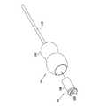
図2Aは本発明の一定の実施形態による患者26の大腿骨等のような一定の骨50の中へのねじ30の移植を示している概略図である。このねじを挿入するために、外科医22は被覆している軟質組織52を通して一定の切開部分を作成した後に、例えば、工具28を用いてそのねじを回転して骨50の中に挿入する。あるいは、このねじは切開の前処理を伴わずに経皮的に挿入することができる。なお、図2Aの実施形態においては、ねじ30は体外の各要素に対する電線による接続を全く有していないことに注目されたい。一般的に、ねじ30は約5mm乃至15mmの長さであり、約2mm乃至4mmの直径である。また、このねじ30が収容しているセンサーによる信号の受信および送信に対する干渉を避けるために、このねじ30は一般的に一定の非磁性材料により構成されており、この材料は種々の金属、合金、セラミック、プラスチックまたはこれらの材料の一定の組み合わせ物を含むことができる。さらに、このねじ30の中の回路の構成および動作が図3Aおよび図3Bに基づいて以下において説明されている。 FIG. 2A is a schematic diagram illustrating implantation of
図2Bは本発明の代替的な実施形態による別の位置センサー装置54を示している概略的な断面図である。この装置54は一定の移植可能なねじ56を含み、このねじ56は一定の外部装置60に対して電線58を介して連結している。このねじ56は上記のねじ30と実質的に同一の様式で骨50の中に挿入されている(ただし、各電線58が軟質組織52を通して患者の体外に出ている)。しかしながら、この場合には、装置54の一部の要素が外部装置60の中に収容されているので、ねじ56は一般に上記のねじ30よりも小さく作成することができる。例えば、ねじ56は約5mm乃至10mmの長さ、および約2mm乃至4mmの直径にすることができる。このような減少したねじの大きさは骨50に対する傷害および可能な損傷を軽減することに役立つ。さらに、上記装置54の詳細が図4において示されている。 FIG. 2B is a schematic cross-sectional view illustrating another
図3Aは本発明の一定の実施形態による上記ねじ30の中に収容されている一定の無線式の位置センサー70の概略的で絵画的な図である。この実施形態におけるセンサー70は3組のコイル、すなわち、センサー・コイル72、出力コイル74、および一定の通信コイル76を含む。あるいは、これらの出力および通信の各コイルの機能は上記の米国特許出願第10/029,473号において記載されているように組み合わせることができる。さらに、または、あるいは、通信コイル76はねじ30の長手軸に対して垂直な一定の平面内に巻かれて図3Aにおいて示されているが、この通信コイルまたはアンテナはこの代わりにこのねじの長手軸に対してほぼ平行にセンサー70の長さに沿って配列することも可能である。さらに、上記のコイル72,74および76は一定の電子処理回路78に連結しており、この回路78は一定の柔軟なプリント回路基板(PCB)等のような一定の適当な基板80に取り付けられている。なお、この回路78の構成および動作の詳細は米国特許第10/029,473号および上記の米国特許出願第10/706,298号において記載されており、これらの文献は本明細書において参考文献として含まれる。 FIG. 3A is a schematic, pictorial illustration of a
簡単にするために、図3Aは単一のセンサー・コイル72および単一の出力コイル74のみを示しているが、実際には、センサー70は一般的に3個のセンサー・コイルおよび3個の出力コイル等のようなそれぞれの種類の多数個のコイルを含む。さらに、これらのセンサー・コイルは一定のセンサー・コア82の周囲に相互に直交している方向に一体に巻かれており、出力コイルは一定の出力コア84の周囲に相互に直交している方向に一体に巻かれている。一般的に、これらの3個の出力コイルのそれぞれは少なくとも約40μmの一定の直径を有する約30巻き乃至40巻きの電線を含み、一面が約1.5mm乃至2mmの一定のフェライトの立方体である。一方、上記3個のセンサー・コイルのそれぞれは一般的に約700巻き乃至3000巻きの11μmの電線を含み、上記コア82は一面が約1.8mm乃至2.4mmの一定のフェライトの立方体である。(なお、これらの寸法が例示のために記載されていて、これらの寸法が実際には一定の相当な範囲にわたり変更可能であることが理解されると考える。)あるいは、上記のセンサーおよび出力のコイルは、例えば、2004年1月9日に出願されている米国特許出願第10/754,751号において記載されているような同一のコアの上に重ねることも可能であり、この文献の開示は本明細書において参考文献として含まれる。しかしながら、これらのコイルを一定の誘電体の層により互いに分離して(あるいは、出力およびセンサーの両方に対して一定の共通のコアを用いる場合にこれらのコイルをインターリーブすることにより)各コイルの間の寄生容量を減少することが一般に望ましい。 For simplicity, FIG. 3A shows only a
動作において、上記出力コイル74はセンサー70のための一定の出力供給源として作用する。これらの出力コイルは一定の外部駆動用のアンテナからの誘導性の連結によりエネルギーを受け取る(例えば、図6Aにおいて示されている)。一般的に、この駆動用のアンテナは13.5MHzの範囲内等のような一定の比較的に高い高周波(RF)において一定の強い電磁場を放射する。さらに、この駆動用の場は上記コイル74の中に電流を生じ、この電流は上記回路78に電力供給するために整流されている。一方、場の発生装置のコイル32(図1)は上述したように各センサー・コイル72をまたいで展開する時変性の信号電圧を誘発する。さらに、回路78はこれらの信号電圧を感知して、これらに応答してそれぞれの出力信号を発生する。なお、これらの出力信号はアナログまたはデジタルのいずれの形態にすることも可能である。これにより、上記回路78は通信コイルを駆動して患者の体外における一定の受信用のアンテナ(図6Aにおいても示されている)に上記の出力信号を送信する。一般的に、上記の出力信号は、例えば、一定の周波数変調方式を用いて43MHzまたは915MHzの範囲内の周波数等のようなさらに高い高周波で送信される。さらに、または、あるいは、上記コイル76は患者の体外における一定の送信アンテナ(図示されていない)から、一定のクロック信号等のような、制御信号を受信するために使用可能である。なお、特定の周波数の範囲が例示を目的として上記において記載されているが、当業界における熟練者は同一の目的のために別の周波数の範囲が使用可能であることが認識できる。 In operation, the
別の実施形態において、図面において示されていないが、上記センサー・コイル72が非同心状になっている。この実施形態において、上記センサー・コイルのそれぞれは一般的に約0.5mm乃至1.3mmの一定の内径を有しており、約2000巻き乃至3000巻きの11μmの直径の線を含み、約1mm乃至1.9mmの一定の全体的なコイルの直径を形成している。(上述したように、これらの直径は例示を目的として示されており、実際の寸法は変更可能である。)例えば、上記センサー・コイルの線の寸法は10μm乃至31μmの範囲にすることができ、その巻き数はその最大の可能な寸法および線の直径に応じて300乃至3000にすることができる。また、上記センサー・コイルの有効な捕捉領域は一般に全体の寸法の必要条件に従って実行可能な限りに大きく作成されている。さらに、これらのセンサー・コイルは一般的に円筒形であるが、別の形状も使用可能である。例えば、ねじ30の形状に応じて、バレル形または正方形のコイルも使用可能である。 In another embodiment, not shown in the drawings, the
図3Bは本発明の別の実施形態による無線式の位置センサー90の概略的で絵画的な図である。このセンサー90はこのセンサー90が上記出力コイル74の代わりにその電力供給源として一定の電池92を備えている点において上記センサー70と異なっている。この電池92は1回使用型または再充電可能型のいずれかの任意の適当な種類とすることができる。また、他の点において、このセンサー90の動作は上記のセンサー70の動作に実質的に類似している。このような電池92の使用は比較的に多量の動作電力を電子処理回路78に供給できると言う利点を有していると共に、センサーに対して誘導性のRF出力を供給するために一定の強い電磁場により患者26を照射する必要性を回避している。一方、センサー90の中に電池92を組み込むことは一般的に上記センサー70に比較してそのセンサーの長さを増大し、それゆえ、そのセンサーを収容するために一定の比較的に長いねじ30の使用が必要になる可能性がある。加えて、上記センサー70の動作寿命は実際上において無制限であるが、センサー90の動作寿命は電池92の寿命により限られている。 FIG. 3B is a schematic and pictorial illustration of a
図4は本発明の実施形態による装置54の詳細を示している一定の概略的で絵画的な図である。この装置54の外部の特徴部分およびその骨50の中への移植は既に図2Bを参照して説明されている。すなわち、この装置54はねじ56の中に収容されている一定の内部感知装置94を含む。一般的に、この感知装置94はセンサー・コイル72のみを収容しており、さらに可能であればまたは随意的に回路78の各要素も収容している。このような構成はねじ56の寸法を最小にすることを可能にしている。さらに、外部装置60は一般的に一定の電池96および回路要素98を収容しており、この回路要素98は上記回路78の一部または全部(回路78のどれだけの部分が感知装置94の中に存在しているかによる)、ならびに、通信コイル76を含む。従って、上記の電池はねじ56を骨から取り外すことなく必要な時に交換できる。一方、上記のセンサー70およびセンサー90はねじ30の中に完全に収容されているので、患者の体外に全く要素が突出しておらず、装置54は外部装置60が上記の感知装置94に操作可能に連結してこの感知装置94に対して連絡する電線58に体外において接続している時にのみ動作できる。 FIG. 4 is a schematic, pictorial illustration showing details of the
図5は本発明の一定の実施形態による工具28の詳細を示している概略的で絵画的な図である。この工具28は一定のハンドル100および一定の軸部102を含む。さらに、一定の工具センサー104がハンドル100の内側の一定の適当なレセプタクルの中に適当に嵌合する。このセンサー104は感知および通信用の回路106を含み、この回路106は一定の電池108により電力供給される。一般的に、この回路106は、上記センサー90(図3B)におけるように、3個の感知用のコイル、一定の通信用のコイルおよび処理回路を含む。これらの感知用のコイルは上記コイル72に類似しており、場の発生装置のコイル32(図1)により発生される磁場に対するセンサー104の位置および配向を感知する。また、通信用のコイルはコンピュータ36に位置信号を送る。上記回路106の動作は従って上記の回路70および回路90におけるそれぞれの回路の動作に類似しているが、この回路106の各要素は上記のセンサー70およびセンサー90において対応する各要素よりも大きく多くの電力を消費する。 FIG. 5 is a schematic, pictorial illustration showing details of the
工具センサー104は工具28の中に永久的に収容することができ、あるいは、このセンサーは(例えば、電池108を交換するために)取り外し可能にすることも可能である。上記工具28の形状が分かっているので、センサー104により示されるハンドル100の位置および配向は軸部102の先端部分の位置および配向を正確に示す。あるいは、上記工具センサー104は小型化することができ、それゆえ、軸部102の中に収容することも可能である。随意的に、上記工具センサー104は上記軸部の位置を測定する精度を高めるために使用する前に較正することができる。 The
図6Aおよび図6Bはそれぞれ本発明の一定の実施形態による一定の手術台112における一定の開口部の中への一定の位置決めパッド110の挿入を示している概略的で絵画的な図である。このパッド110は上記構造40の代わりに上記システム20(図1)における基準構造として用いることができる。このパッド110は一定の一体の装置またはユニットを含み、この装置はそれぞれ固定された位置にある3個の場の発生装置のコイル32を保持している。この装置は一般的にカーボン・ファイバー、グラス・ファイバー、プラスチックまたはセラミック等のような非磁性材料により作成されている。また、この場合の場の発生装置のコイルは内側に直交して角度が付けられている。図6Aにおいて、上記パッド110は手術台の中に挿入する前の状態で示されているが、図6Bにおいては、このパッドが摺動して中に移動している。 6A and 6B are schematic and pictorial views illustrating insertion of a
上記位置決めパッド110は一定の随意的な出力コイル114および一定の通信コイル116も含めて図6Aにおいて示されている。この出力コイル114は電線(図示されていない)により駆動回路34に連結していて、上述したように、センサー70(図3A)の中の出力コイル74に誘導により電力供給するために電力を供給するための一定の電磁場を発生する。(ただし、一定の電池電力供給型のセンサーを用いる場合には、この出力コイルは必要とされない。)その後、通信コイル116が患者の体内に移植されている各センサー内の通信コイル76ならびに工具センサー104により送信される信号を受信する。また、上記通信コイル116は移植されている各センサーおよび工具センサーに対して一定のクロック信号等のような種々の制御信号を送信するために使用することも可能である。この通信コイル116は電線(図示されていない)によりコンピュータ36に連結されている。このコンピュータは通信コイル116から受け取った各信号を処理してそれぞれのセンサーの位置および配向を決定する。上記のコイル114およびコイル116は図6Aにおいて示されているように上記パッド110の表面上に印刷可能であり、あるいは、パッド110の内側に収容されている印刷した回路線または巻線コイルを含むことができる。 The
図6Bは駆動回路34により駆動される場合の場の発生装置の各コイル32を概略的に示している図である。この場合の動作空間の表面は追跡システム20が特定の精度の範囲内にセンサーの各座標、すなわち、そのセンサーのそれぞれの位置座標または位置および配向の各座標を決定できる一定の領域の外側の限界域を示している。なお、この必要とされる精度は当面の外科処置を行なう場合に外科医22により必要とされる位置決め精度の程度等のような種々の機能的な考察により決定される。一般的に、上記動作空間118の外表面部は追跡の精度が1mm乃至2mmの範囲に低下する空間内の限界域を示している。また、図6Aおよび図6Bにおいて示されているような場の発生装置の各コイルの傾斜は上記動作空間の集中度を低下する。上記パッド110は剛体であるので、図1において構造40が可能としているような上昇および下降または傾斜ができない。しかしながら、上記パッド110は手術台に沿って動作空間118の位置をずらすためにその台112から出入りするために摺動できるので、その動作空間は外科医が手術している骨50またはその一部分を捕らえることができる。 FIG. 6B is a diagram schematically showing each
図7は本発明の一定の実施形態による患者26の一定の膝120の手術に用いるために上記基準構造40を調節可能にする方法を示している概略的で絵画的な図である。この患者は一定の手術台122の上に寝ており、この手術台122は外科医が患者の膝の関節に都合よく接近できるように図において示されているように折れ曲がっている。さらに、基本構造40の基部44は追随的に傾斜して、場の発生装置の各コイル32の動作空間が膝120の領域を含むと共に外科医がその領域に接近することが妨げられないようになっている。 FIG. 7 is a schematic, pictorial illustration showing a method for making the
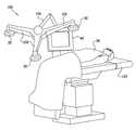
図8は本発明の別の実施形態による場の発生装置の各コイル32を支持するための一定の基準構造130を示している概略的で絵画的な図である。この構造130は各コイル32を保持する幾つかのアーム132を含む。これらのアーム132は一定の関節状に動作するブーム134に固定されており、このブーム134はそれぞれの場の発生装置のコイル32の高さおよび角度を手術台136の上の患者の位置に対して調節可能にする。さらに、上記ブーム134は一定の車輪付のカート138により搬送可能であるので、上記構造130は手術台136の両側またはその台の足部または頭部に位置決めできる。上記カート138はまたコンピュータ36および/または駆動回路34も含むことができる。さらに、手術台136の上方の混雑を減少するために、上記構造130を図面において示されているように一定の頭上ランプ(電灯)140と一体にすることも可能である。このような構成において、ランプ140は各コイル132の動作空間の領域を照明する。また、一定の付加的なランプ142が補足的に示されている。 FIG. 8 is a schematic, pictorial illustration showing a
図9は本発明のさらに別の実施形態による場の発生装置の各コイル32を支持している一定の基準構造150を示している概略的で絵画的な図である。この構造150は一定の関節状に動作するブーム154を含み、このブーム154は各コイル32が取り付けられているアーム152を保持している。このような実施形態において、上記構造150は傾斜して患者の膝の領域の上方に位置決めされることにより、図7において示されている構造と類似の機能を果たす。 FIG. 9 is a schematic, pictorial illustration showing a
図10Aおよび図10Bは本発明の別の実施形態による別の基準構造160を示している概略的で絵画的な図である。この構造160は一定の基部164に取り付けられている場の発生装置の各コイル32のための一定の半円形のホルダー162を含む。上記の幾つかの実施形態における基準構造は手術されている骨(大腿骨または腓骨等)の長手軸にほぼ平行な一定の平面内において各コイル32を位置決めするように構成されていたが、構造160の平面はこの軸に対してほぼ垂直である。一般的に、上記動作空間の適当な位置決めのために、上記構造160は上記骨の軸が各コイル32の位置により定められる円の中を通過するように、すなわち、上記ホルダー162が骨の軸を部分的に囲うように配置されている。 10A and 10B are schematic and pictorial views showing another
上記構造160は車輪付きの一定のカート166に取り付けられていて、手術台122の足部(図10A)または頭部(図10B)のいずれかに位置決めすることが可能である。さらに、基部164における一定の調節スロット167またはその他の機構がホルダー162の患者の回りにおける回転を可能にしている。また、一定のヒンジ部が基部164の傾斜を可能にしており、入れ子式の足部170が全体の構造の上昇または下降を可能にしている。従って、この構造160は行なう処置の種類に応じて外科医の都合により柔軟に位置決めすることが可能である。例えば、図10Aの構成は腰部の手術に好都合であるが、図10Bの構成は膝の手術において都合が良い。 The
図11は本発明のさらに別の実施形態による手術において使用するための一定の磁気追跡システムを示している概略的で絵画的な図である。この実施形態において、上記の追跡システムは一定の手術台182に一体である。また、手術台はこの目的のためにあつらえ式にすることができ、それゆえ、磁性材料をほとんどまたは全く含まない。さらに、一定の基準構造184が一定の関節状に動作する取付部材により手術台182の下面部に固定されており、この取付部材は、場の発生装置の各コイル32を当面の外科処置に必要とされる状態に位置決めするために、上記構造184の回転、傾斜、上昇および下降を可能にする。また、手術台182の入れ子式の基部186は幾つかの駆動回路34およびコンピュータ36を収容している。さらに、それぞれの位置センサーおよび工具の位置および配向が表示装置46に示され、この表示装置も同様に手術台182に一体になっている。従って、上記システム180は外科医が磁気による位置追跡の使用による付加的な手間を最少にして手術することを可能にする。 FIG. 11 is a schematic and pictorial diagram illustrating a magnetic tracking system for use in surgery according to yet another embodiment of the present invention. In this embodiment, the tracking system described above is integral to an operating table 182. The operating table can also be tailored for this purpose and therefore contains little or no magnetic material. In addition, a fixed
上記の各実施形態は時変性の磁場を用いる追跡システムに具体的に関連しているが、本発明の原理は超音波追跡システムおよび直流磁場に基づく追跡システム等のような別の種類の追跡システムにおいても、必要な変更を加えて、適用可能である。従って、上記の各実施形態が例示を目的としていること、および本発明が上記において特定的に図示および説明されている内容に限定されないことが認識されると考える。むしろ、本発明の範囲は上記の種々の特徴の種々の組み合わせおよび副次的な組み合わせ、ならびに、上記の説明を読むことにより当業界における熟練者において思いつくと考えられ、従来技術において開示されていない上記の特徴の種々の変形および変更を含む。 Although each of the above embodiments is specifically related to a tracking system that uses a time-varying magnetic field, the principles of the present invention are another type of tracking system, such as an ultrasonic tracking system and a DC magnetic field based tracking system. However, it can be applied with necessary changes. Accordingly, it will be appreciated that the above embodiments are for illustrative purposes and that the present invention is not limited to what is specifically shown and described above. Rather, the scope of the present invention is believed to occur to those skilled in the art upon reading various combinations and subcombinations of the various features described above, and the above description, and is not disclosed in the prior art. It includes various variations and modifications of the above features.
本発明の具体的な実施態様は以下のとおりである。
(1)外科追跡システムにおいて、一定の無線式位置センサーを備えており、この位置センサーは一定の被験体の骨の中に移植すること、および前記追跡システムの一定の動作空間の中の外部から供給された磁場に応答して、前記骨の中の当該位置センサーの各座標を示すセンサー信号を発生して送信することに適合しており、さらに複数の磁場の発生装置のコイルを備えており、これらのコイルは前記動作空間を定めるためにそれぞれの磁場を発生することに適合しており、さらに一定の基準構造を備えており、この基準構造に前記場の発生装置のコイルがそれぞれの所定の位置において固定されており、この基準構造が前記骨を捕らえるように前記動作空間を位置決めするために前記被験体に対して移動可能であり、さらに一定のシステム・コントローラを備えており、このシステム・コントローラが前記骨の中の位置センサーの各座標を決定するために前記センサー・信号を受信して処理するために連結されている外科追跡システム。
(2)前記基準構造が、多数のアームを含み、これらのそれぞれが前記場の発生装置のコイルのそれぞれ1個を保持しており、さらに前記アームを支持するために連結している一定の基部を含む実施態様(1)に記載のシステム。
(3)前記基部が前記アームの一定の高さ、回転および傾斜の内の少なくとも一つを調節すると共に、これらのアームを一定の固定した相互関係に維持することに適合している実施態様(2)に記載のシステム。
(4)前記基準構造が多数のアームを含み、これらのそれぞれが前記場の発生装置のコイルのそれぞれ1個を保持しており、さらに前記アームを前記被験体の上方に支持するために連結している一定のブームを含む実施態様(1)に記載のシステム。
(5)前記ブームが前記アームの一定の高さ、回転および傾斜の内の少なくとも一つを調節すると共に、これらのアームを一定の固定した相互関係に維持することに適合している実施態様(4)に記載のシステム。Specific embodiments of the present invention are as follows.
(1) In a surgical tracking system, a wireless position sensor is provided, which is implanted in a subject's bone, and from outside the tracking system's constant operating space. Adapted to generate and transmit a sensor signal indicating each coordinate of the position sensor in the bone in response to a supplied magnetic field, and further comprising a coil of a plurality of magnetic field generators The coils are adapted to generate respective magnetic fields to define the operating space, and are provided with a certain reference structure, to which the coils of the field generator are respectively assigned The reference structure is movable relative to the subject to position the motion space to capture the bone, and a fixed system. · Includes a controller, a surgical tracking system to which the system controller is coupled to receive and process the sensor signals to determine the coordinates of the position sensor within the bone.
(2) The reference structure includes a number of arms, each of which holds a respective one of the coils of the field generator and is further connected to support the arms The system according to embodiment (1), comprising:
(3) An embodiment wherein the base is adapted to adjust at least one of the constant height, rotation and tilt of the arms and to maintain the arms in a fixed and fixed relationship ( The system according to 2).
(4) The reference structure includes a number of arms, each of which holds a respective one of the coils of the field generator, and further coupled to support the arms above the subject. The system of embodiment (1), comprising a boom that is fixed.
(5) An embodiment wherein the boom is adapted to adjust at least one of a constant height, rotation and tilt of the arms and to maintain the arms in a fixed and fixed relationship. The system according to 4).
(6)さらに、一定の電灯を備えており、この電灯が前記ブームにより前記被験体の上方に保持されて前記動作空間の一定の領域を照明するようになっている実施態様(4)に記載のシステム。
(7)前記骨が一定の軸を有しており、前記場の発生装置が前記基準構造に固定されているそれぞれの位置が一定の平面を定めており、さらに前記基準構造が前記軸に対して前記平面がほぼ平行になるように前記場の発生装置を位置決めすることに適合している実施態様(1)に記載のシステム。
(8)前記骨が一定の軸を有しており、前記場の発生装置が前記基準構造に固定されているそれぞれの位置が一定の平面を定めており、さらに前記基準構造が前記軸に対して前記平面がほぼ垂直になるように前記場の発生装置を位置決めすることに適合している実施態様(1)に記載のシステム。
(9)前記基準構造が一定の半円形のホルダーを含み、この半円形のホルダーに前記場の発生装置が固定されており、この半円形のホルダーが前記軸を部分的に囲う実施態様(8)に記載のシステム。
(10)前記基準構造が一定の基部を含み、この基部に前記半円形のホルダーが移動可能に取り付けられていて、この半円形のホルダーの一定の高さ、回転および傾斜の内の少なくとも一つを調節すると共に、前記場の発生装置を一定の固定した相互関係に維持することを可能にしている実施態様(9)に記載のシステム。(6) In the embodiment (4), further comprising a certain electric lamp, the electric lamp being held above the subject by the boom to illuminate a certain area of the operation space. System.
(7) The bone has a fixed axis, and each position where the field generating device is fixed to the reference structure defines a fixed plane, and the reference structure is in relation to the axis. The system of claim 1, wherein the system is adapted to position the field generator such that the planes are substantially parallel.
(8) The bone has a fixed axis, and each position where the field generating device is fixed to the reference structure defines a fixed plane, and the reference structure is in relation to the axis. A system according to embodiment (1) adapted to position the field generator such that the plane is substantially vertical.
(9) Embodiment in which the reference structure includes a semicircular holder, the field generating device is fixed to the semicircular holder, and the semicircular holder partially surrounds the shaft (8) ) System.
(10) The reference structure includes a fixed base, and the semicircular holder is movably attached to the base, and at least one of the fixed height, rotation, and inclination of the semicircular holder. A system according to embodiment (9), wherein said field generating device can be adjusted and maintained in a fixed and fixed relationship.
(11)さらに、一定の下面部を有していて、前記システム・コントローラを収容している一定の基部を含む一定の手術台を備えており、前記基準構造が多数のアームを含み、これらのそれぞれが前記場の発生装置のコイルのそれぞれ1個を保持しており、さらに前記基準構造が一定の関節状に動作する取付部材を含み、この取付部材に前記アームが固定されており、この取付部材がそれぞれのアームを支持するために前記手術台の下面部に固定されている実施態様(1)に記載のシステム。
(12)前記関節状に動作する取付部材が前記アームの一定の高さ、回転および傾斜の内の少なくとも一つを調節すると共に、これらのアームを一定の固定した相互関係に維持することに適合している実施態様(11)に記載のシステム。
(13)前記基準構造が一定の手術台の中の一定の開口部の中に挿入するように構成されている実施態様(1)に記載のシステム。
(14)前記位置センサーが1個以上のセンサー・コイルを含み、これらのセンサー・コイルが前記磁場を感知してそれぞれのセンサー信号を発生することに適合している実施態様(1)に記載のシステム。
(15)さらに、一定の駆動用のアンテナを備えており、このアンテナが前記センサーに向けて一定の高周波(RF)の電磁場を放射することに適合しており、さらに前記位置センサーが一定の出力コイルを含み、この出力コイルが前記RFの電磁場を受信して前記センサーに電力を供給するために連結している実施態様(14)に記載のシステム。(11) and further comprising a certain operating table having a certain bottom surface and including a certain base accommodating the system controller, wherein the reference structure includes a plurality of arms, Each holding one of the coils of the field generator, and the reference structure further includes a mounting member that operates in a certain joint shape, and the arm is fixed to the mounting member. The system of embodiment (1), wherein a member is secured to the underside of the operating table to support each arm.
(12) The articulating mounting member is adapted to adjust at least one of the constant height, rotation and tilt of the arms and to maintain the arms in a fixed and fixed relationship. A system according to embodiment (11).
(13) The system according to embodiment (1), wherein the reference structure is configured to be inserted into a certain opening in a certain operating table.
(14) The embodiment according to (1), wherein the position sensor comprises one or more sensor coils, the sensor coils being adapted to sense the magnetic field and generate respective sensor signals. system.
(15) Further, a constant driving antenna is provided, the antenna is adapted to radiate a constant high frequency (RF) electromagnetic field toward the sensor, and the position sensor has a constant output. The system of claim 14 including a coil, the output coil coupled to receive the RF electromagnetic field and provide power to the sensor.
(16)前記位置センサーが一定の通信コイルを含み、この通信コイルが前記システム・コントローラに前記センサー信号を送信するために連結している実施態様(14)に記載のシステム。
(17)さらに、一定のねじを備えており、このねじが前記位置センサーの少なくとも1個以上のセンサー・コイルを収容していて、前記骨の中に挿入することに適合している実施態様(14)に記載のシステム。
(18)前記位置センサーが一定の電力供給源を含み、この電力供給源が前記ねじの中に収容されている実施態様(17)に記載のシステム。
(19)前記位置センサーが一定の外部装置を含み、この外部装置が少なくとも1個の電力供給源を含み、前記被験体の体外に位置決めされることに適合しており、さらに前記ねじの中の1個以上のセンサー・コイルを前記外部装置に連結している電線を含む実施態様(17)に記載のシステム。
(20)さらに、前記骨を手術するための一定の外科工具を備えており、この工具が一定の工具位置センサーを含み、この工具位置センサーが前記外部から供給される磁場に応じて、前記骨に対する前記工具の各座標を示す工具信号を発生して送信することに適合している実施態様(1)に記載のシステム。(16) The system of embodiment (14), wherein the position sensor includes a communication coil, the communication coil being coupled to transmit the sensor signal to the system controller.
(17) An embodiment further comprising a constant screw, the screw containing at least one sensor coil of the position sensor and adapted to be inserted into the bone ( 14) The system described in 14).
(18) The system of embodiment (17), wherein the position sensor includes a constant power supply, the power supply being housed in the screw.
(19) The position sensor includes an external device, the external device includes at least one power supply, and is adapted to be positioned outside the subject's body, and further in the screw The system of embodiment (17), comprising an electrical wire connecting one or more sensor coils to the external device.
(20) Furthermore, a certain surgical tool for operating the bone is provided, the tool includes a certain tool position sensor, and the tool position sensor according to the magnetic field supplied from the outside, The system of embodiment (1) adapted to generate and transmit a tool signal indicative of each coordinate of the tool relative to.
(21)外科手術のための方法において、一定の被験体の骨の中に一定の無線式の位置センサーを移植する処理を含み、この位置センサーが外部から供給される磁場に応答して前記骨の中の位置センサーの各座標を指示するセンサー信号を発生して送信することに適合しており、さらに一定の基準構造における所定の位置に複数の場の発生装置のコイルをそれぞれ取り付ける処理、前記場の発生装置のコイルを駆動してそれぞれの磁場を発生することにより、前記無線式の位置センサーを追跡するための一定の動作空間を定める処理、前記骨を捕らえるために前記動作空間を位置決めするために前記基準構造を移動する処理、および前記骨の中の位置センサーの各座標を決定するために前記センサー信号を受信して処理する処理を含む方法。
(22)前記基準構造が、多数のアームを含み、これらのそれぞれが前記場の発生装置のコイルのそれぞれ1個を保持しており、さらに前記アームを支持するために連結している一定の基部を含む実施態様(21)に記載の方法。
(23)前記基部が前記アームの一定の高さ、回転および傾斜の内の少なくとも一つを調節すると共に、これらのアームを一定の固定した相互関係に維持することに適合している実施態様(22)に記載の方法。
(24)前記基準構造が多数のアームを含み、これらのそれぞれが前記場の発生装置のコイルのそれぞれ1個を保持しており、さらに前記アームを前記被験体の上方に支持するために連結している一定のブームを含む実施態様(21)に記載の方法。
(25)前記ブームが前記アームの一定の高さ、回転および傾斜の内の少なくとも一つを調節すると共に、これらのアームを一定の固定した相互関係に維持することに適合している実施態様(24)に記載の方法。(21) In a method for surgery, the method includes a process of implanting a wireless position sensor in a bone of a subject, the position sensor being responsive to an externally supplied magnetic field. A process adapted to generate and transmit a sensor signal indicating each coordinate of a position sensor in the sensor, and further attach each of a plurality of field generator coils to a predetermined position in a fixed reference structure, A process for defining a constant operating space for tracking the wireless position sensor by driving the coils of the field generating device to generate the respective magnetic fields, and positioning the operating space for capturing the bone A method comprising: moving the reference structure to receive and processing to receive and process the sensor signal to determine each coordinate of a position sensor in the bone.
(22) The base structure includes a number of arms, each of which holds a respective one of the coils of the field generator and is further connected to support the arms A method according to embodiment (21) comprising:
(23) The embodiment wherein the base is adapted to adjust at least one of the constant height, rotation and tilt of the arms and to maintain the arms in a fixed and fixed relationship ( 22).
(24) The reference structure includes a number of arms, each of which holds a respective one of the coils of the field generator, and further coupled to support the arms above the subject. Embodiment 21. A method according to embodiment (21) comprising a boom.
(25) An embodiment wherein the boom is adapted to adjust at least one of a constant height, rotation and tilt of the arms and to maintain the arms in a fixed and fixed relationship. 24) The method.
(26)前記骨が一定の軸を有しており、前記場の発生装置が前記基準構造に固定されているそれぞれの位置が一定の平面を定めており、さらに前記基準構造が前記軸に対して前記平面がほぼ平行になるように前記場の発生装置を位置決めすることに適合している実施態様(21)に記載の方法。
(27)前記骨が一定の軸を有しており、前記場の発生装置が前記基準構造に固定されているそれぞれの位置が一定の平面を定めており、さらに前記基準構造が前記軸に対して前記平面がほぼ垂直になるように前記場の発生装置を位置決めすることに適合している実施態様(21)に記載の方法。
(28)前記基準構造が一定の半円形のホルダーを含み、この半円形のホルダーに前記場の発生装置が固定されており、この半円形のホルダーが前記軸を部分的に囲う実施態様(27)に記載の方法。
(29)前記基準構造が一定の基部を含み、この基部に前記半円形のホルダーが移動可能に取り付けられており、前記基準構造を移動する処理が前記基部に対する前記半円形のホルダーの一定の高さ、回転および傾斜の内の少なくとも一つを調節すると共に、前記場の発生装置を一定の固定した相互関係に維持する処理を含む実施態様(28)に記載の方法。
(30)前記基準構造が多数のアームを含み、これらのそれぞれが前記場の発生装置のコイルのそれぞれ1個を保持しており、さらに前記基準構造が一定の関節状に動作する取付部材を含み、この取付部材に前記アームが固定されており、この取付部材がそれぞれのアームを支持するために一定の手術台の下面部に固定されている実施態様(21)に記載の方法。(26) The bone has a fixed axis, and each position where the field generating device is fixed to the reference structure defines a fixed plane, and the reference structure is further relative to the axis. A method according to embodiment (21) adapted to position the field generator such that the planes are substantially parallel.
(27) The bone has a fixed axis, and each position where the field generating device is fixed to the reference structure defines a fixed plane, and the reference structure is in relation to the axis. A method according to embodiment (21), adapted to position the field generator such that the plane is substantially vertical.
(28) The embodiment (27), wherein the reference structure includes a semicircular holder, and the field generating device is fixed to the semicircular holder, and the semicircular holder partially surrounds the shaft. ) Method.
(29) The reference structure includes a fixed base, and the semicircular holder is movably attached to the base, and the process of moving the reference structure is performed at a fixed height of the semicircular holder with respect to the base. 29. A method according to embodiment (28), comprising the step of adjusting at least one of rotation and tilt and maintaining the field generator in a fixed and fixed relationship.
(30) The reference structure includes a plurality of arms, each of which holds one of the coils of the field generator, and the reference structure includes a mounting member that operates in a certain joint shape. The method according to embodiment (21), wherein the arm is fixed to the mounting member, and the mounting member is fixed to a lower surface portion of a certain operating table to support each arm.
(31)前記基準構造を移動する処理が前記アームの一定の高さ、回転および傾斜の内の少なくとも一つを調節すると共に、これらのアームを一定の固定した相互関係に維持する処理を含む実施態様(30)に記載の方法。
(32)前記基準構造が一定の手術台の中の一定の開口部の中に挿入するように構成されている実施態様(21)に記載の方法。
(33)前記位置センサーが1個以上のセンサー・コイルを含み、これらのセンサー・コイルが前記磁場を感知して前記各座標を指示する信号を発生することに適合している実施態様(21)に記載の方法。
(34)前記位置センサーが一定の出力コイルを含み、この出力コイルが一定の高周波(RF)の電磁場を受信して前記センサーに電力を供給するために連結しており、前記方法が前記RFの電磁場を一定の駆動用のアンテナを用いて前記センサーに向けて放射する処理を含む実施態様(33)に記載の方法。
(35)前記位置センサーが一定の通信コイルを含み、この通信コイルが前記センサー信号を送信するために連結している実施態様(33)に記載の方法。(31) An implementation in which the process of moving the reference structure includes a process of adjusting at least one of the constant height, rotation, and tilt of the arms and maintaining the arms in a fixed fixed relationship. A method according to embodiment (30).
(32) The method of embodiment (21), wherein the reference structure is configured to be inserted into an opening in an operating table.
(33) The embodiment (21), wherein the position sensor includes one or more sensor coils, the sensor coils being adapted to sense the magnetic field and generate signals indicative of the coordinates. The method described in 1.
(34) The position sensor includes a constant output coil, the output coil is coupled to receive a constant radio frequency (RF) electromagnetic field and supply power to the sensor, the method comprising the RF The method of embodiment (33), comprising a process of radiating an electromagnetic field toward the sensor using a constant driving antenna.
(35) The method of embodiment (33), wherein the position sensor includes a communication coil, the communication coil being coupled to transmit the sensor signal.
(36)前記無線式の位置センサーを移植する処理が前記位置センサーの少なくとも1個以上のセンサー・コイルを一定のねじの中に挿入して、このねじを前記骨の中に挿入する処理を含む実施態様(33)に記載の方法。
(37)前記位置センサーが一定の電力供給源を含み、この電力供給源が前記ねじの中に収容されている実施態様(36)に記載の方法。
(38)前記無線式の位置センサーを移植する処理が前記ねじの中の1個以上のセンサー・コイルを前記被験体の体外の一定の外部装置に連結する処理を含み、この外部装置が少なくとも1個の電力供給源を含む実施態様(36)に記載の方法。
(39)さらに、一定の工具位置センサーを含む一定の外科工具を用いて前記骨に一定の外科処置を行なう処理を含み、この工具位置センサーが前記外部から供給される磁場に応じて、前記骨に対する前記工具の各座標を示す工具信号を発生して送信することに適合している実施態様(21)に記載の方法。(36) The process of implanting the wireless position sensor includes the process of inserting at least one sensor coil of the position sensor into a screw and inserting the screw into the bone. The method according to embodiment (33).
(37) A method according to embodiment (36), wherein said position sensor comprises a constant power supply, which is housed in said screw.
(38) The process of implanting the wireless position sensor includes the process of coupling one or more sensor coils in the screw to an external device outside the subject's body, the external device comprising at least one The method of embodiment (36) comprising one power source.
(39) The method further includes a process of performing a certain surgical operation on the bone using a certain surgical tool including a certain tool position sensor, and the tool position sensor is configured to generate the bone according to a magnetic field supplied from the outside. A method according to embodiment (21) adapted to generate and transmit a tool signal indicative of each coordinate of the tool relative to.
本発明は一定の患者の体内の物体の位置を追跡することにおいて使用するための磁気追跡システムに適用できる。一部の実施形態において、これらのシステムは種々のねじ、釘、棒材またはプロテーゼ関節または任意の他の整形外科用の装置または工具等のような移植片の移植を含む種々の整形外科処置において用いられる。この目的のために、無線方式の磁気位置センサーを患者の骨の中に挿入することができ、あるいは、患者の骨の中にまたは種々のプロテーゼ移植片および手術中に用いる種々の工具の中に挿入できる種々のねじ、釘、棒材等のような移植片またはその他の整形外科装置の中に挿入できる。上記の追跡システムは種々のセンサーの座標を決定し、これにより、外科医が手術中のX線画像処理の必要性を減少するか排除すると共にそれぞれの要素の位置および配向を可視化することを可能にする。さらに、移植されたそれぞれのセンサーは術後の追跡調査において用いることも可能である。 The present invention is applicable to a magnetic tracking system for use in tracking the position of an object within a patient's body. In some embodiments, these systems are used in a variety of orthopedic procedures, including graft implantation, such as various screws, nails, bars or prosthetic joints or any other orthopedic device or tool, etc. Used. To this end, a wireless magnetic position sensor can be inserted into the patient's bone or in the patient's bone or in various prosthetic implants and various tools used during surgery. It can be inserted into a graft or other orthopedic device such as various screws, nails, bars, etc. that can be inserted. The tracking system described above determines the coordinates of the various sensors, thereby enabling the surgeon to visualize or reduce the need for intraoperative x-ray imaging and to visualize the position and orientation of each element. To do. In addition, each implanted sensor can be used in post-surgical follow-up.
20 磁気追跡システム
22 外科医
24 足
26 患者
28 工具
30 移植片
32 場の発生装置のコイル
34 駆動回路
36 コンピュータ
40 基準構造
42 アーム
44 基部
50 骨
54 センサー装置
56 ねじ
58 電線
60 外部装置
70 位置センサー
72 センサー・コイル
74 出力コイル
76 通信コイル
78 処理回路
84 出力コア
90 位置センサー
92 電池
94 感知装置
96 電池
98 回路要素
100 ハンドル
102 軸部
104 センサー
106 回路
108 電池
110 パッド
112 手術台
114 出力コイル
116 通信コイル
118 動作空間
120 膝
122 手術台
130 基準構造
140 電灯
150,160 基準構造
180 磁気追跡システム
20
Claims (18)
Translated fromJapanese無線式位置センサーを備えており、この位置センサーは被験体の骨の中に移植すること、および前記追跡システムの動作空間の中の外部から供給された磁場に応答して、前記骨の中の前記位置センサーの各座標を示すセンサー信号を発生して送信することに適合しており、さらに
複数の磁場の発生装置のコイルを備えており、これらのコイルは前記動作空間を定めるためにそれぞれの磁場を発生することに適合しており、さらに
基準構造を備えており、前記基準構造に前記場の発生装置のコイルがそれぞれの所定の位置において固定され、前記基準構造および前記場の発生装置のコイルが上昇、下降、傾斜、および位置をずらすことができ、前記基準構造が前記骨を捕らえるように前記動作空間を位置決めするために前記被験体に対して移動可能であり、さらに
システム・コントローラを備えており、このシステム・コントローラが前記骨の中の位置センサーの各座標を決定するために前記センサー信号を受信して処理するために連結されており、さらに
前記基準構造から分離している手術台を備えており、前記基準構造は、多数のアームと、ブームと、を含み、各アームは、前記場の発生装置のコイルの対応する1個を保持し、ブームは、被験体上方にアームを支持するために連結され、さらに、
電灯を備えており、この電灯は、ブームによって被験体上方に保持されて前記動作空間の領域を照明するようになっている、ことを特徴とする外科追跡システム。In surgical tracking systems,
A wireless position sensor, wherein the position sensor is implanted in the bone of the subject and in response to a magnetic field supplied externally in the operating space of the tracking system. Adapted to generate and transmit sensor signals indicating the coordinates of the position sensor, and further comprising coils of a plurality of magnetic field generators, each of which is provided for defining the operating space. Adapted to generate a magnetic field, further comprising a reference structure, wherein a coil of the field generating device is fixed to the reference structure at each predetermined position, and the reference structure and the field generating device A coil can be raised, lowered, tilted and displaced, and moved relative to the subject to position the operating space such that the reference structure captures the bone. Possible, further comprising a system controller, the system controller coupled to receive and process the sensor signal to determine each coordinate of the position sensor in the bone; An operating table is provided separate from the reference structure, the reference structure including a number of arms and a boom, each arm holding a corresponding one of the coils of the field generator. The boom is coupled to support the arm above the subject, and
A surgical tracking systemcomprising an electric light, the electric light being held above the subject by a boom to illuminate an area of the operating space .
前記基準構造が前記軸に対して前記平面がほぼ平行になるように前記場の発生装置を位置決めすることに適合している請求項1に記載のシステム。The bone has an axis, and each position where the field generator is fixed to the reference structure defines a plane;
The system ofclaim 1, wherein the reference structure is adapted to position the field generator such that the plane is substantially parallel to the axis .
前記基準構造が前記軸に対して前記平面がほぼ垂直になるように前記場の発生装置を位置決めすることに適合している請求項1に記載のシステム。The bone has an axis, and each position where the field generator is fixed to the reference structure defines a plane;
The system ofclaim 1, wherein the reference structure is adapted to position the field generator such that the plane is substantially perpendicular to the axis .
前記位置センサーが出力コイルを含み、この出力コイルが前記RFの電磁場を受信して前記センサーに電力を供給するために連結している請求項12に記載のシステム。And a driving antenna, adapted to radiate a radio frequency (RF) electromagnetic field towards the sensor,
The system ofclaim 12, wherein the position sensor includes an output coil that is coupled to receive the RF electromagnetic field and provide power to the sensor .
外部装置を含み、この外部装置が少なくとも1個の電力供給源を含み、前記被験体の体外に位置決めされることに適合しており、さらに
前記ねじの中の1個以上のセンサー・コイルを前記外部装置に連結している電線を含む請求項15に記載のシステム。The position sensor
Including an external device, the external device including at least one power supply, adapted to be positioned outside the subject's body, and
The system ofclaim 15, comprising a wire connecting one or more sensor coils in the screw to the external device .
Applications Claiming Priority (4)
| Application Number | Priority Date | Filing Date | Title |
|---|---|---|---|
| US062258 | 2004-02-18 | ||
| US55092404P | 2004-03-05 | 2004-03-05 | |
| US550924 | 2004-03-05 | ||
| US11/062,258US8046050B2 (en) | 2004-03-05 | 2005-02-18 | Position sensing system for orthopedic applications |
Publications (2)
| Publication Number | Publication Date |
|---|---|
| JP2005253965A JP2005253965A (en) | 2005-09-22 |
| JP4832774B2true JP4832774B2 (en) | 2011-12-07 |
Family
ID=34976983
Family Applications (1)
| Application Number | Title | Priority Date | Filing Date |
|---|---|---|---|
| JP2005061256AExpired - Fee RelatedJP4832774B2 (en) | 2004-02-18 | 2005-03-04 | Position sensing system in orthopedic applications |
Country Status (7)
| Country | Link |
|---|---|
| US (1) | US8046050B2 (en) |
| EP (3) | EP3381363B1 (en) |
| JP (1) | JP4832774B2 (en) |
| KR (1) | KR20060043399A (en) |
| AU (1) | AU2005200900B2 (en) |
| CA (1) | CA2499457C (en) |
| IL (1) | IL167235A (en) |
Families Citing this family (121)
| Publication number | Priority date | Publication date | Assignee | Title |
|---|---|---|---|---|
| US7300432B2 (en)* | 2004-04-21 | 2007-11-27 | Depuy Products, Inc. | Apparatus for securing a sensor to a surgical instrument for use in computer guided orthopaedic surgery |
| US7776055B2 (en)* | 2004-07-19 | 2010-08-17 | General Electric Company | System and method for tracking progress of insertion of a rod in a bone |
| DE102004037587A1 (en)* | 2004-08-03 | 2006-02-23 | Enocean Gmbh | Energy self-sufficient electronic system |
| US8388553B2 (en) | 2004-11-04 | 2013-03-05 | Smith & Nephew, Inc. | Cycle and load measurement device |
| US20060189867A1 (en) | 2005-02-22 | 2006-08-24 | Ian Revie | Probe |
| US20060241397A1 (en)* | 2005-02-22 | 2006-10-26 | Assaf Govari | Reference pad for position sensing |
| DE202005009809U1 (en)* | 2005-03-31 | 2005-08-25 | Stryker Trauma Gmbh | Patient data transmission system for use with implant, has downlink between internal transmission and receiving units, and uplink between external transmission and receiving units controlling measurement and internal transmission units |
| US20070005141A1 (en) | 2005-06-30 | 2007-01-04 | Jason Sherman | Apparatus, system, and method for transcutaneously transferring energy |
| US7780613B2 (en) | 2005-06-30 | 2010-08-24 | Depuy Products, Inc. | Apparatus, system, and method for transcutaneously transferring energy |
| EP1906815A2 (en)* | 2005-07-12 | 2008-04-09 | Alfred E. Mann Institute for Biomedical Engineering at the University of Southern California | Method and apparatus for detecting object orientation and position |
| US8730011B2 (en)* | 2005-07-14 | 2014-05-20 | Biosense Webster, Inc. | Wireless position transducer with digital signaling |
| AU2006282828B2 (en) | 2005-08-23 | 2013-01-31 | Smith & Nephew, Inc | Telemetric orthopaedic implant |
| US7525309B2 (en) | 2005-12-30 | 2009-04-28 | Depuy Products, Inc. | Magnetic sensor array |
| US8862200B2 (en) | 2005-12-30 | 2014-10-14 | DePuy Synthes Products, LLC | Method for determining a position of a magnetic source |
| US7816915B2 (en)* | 2006-01-06 | 2010-10-19 | Biosense Webster, Inc. | Miniature coils on core with printed circuit |
| US7328131B2 (en)* | 2006-02-01 | 2008-02-05 | Medtronic, Inc. | Implantable pedometer |
| US8016859B2 (en) | 2006-02-17 | 2011-09-13 | Medtronic, Inc. | Dynamic treatment system and method of use |
| US7993269B2 (en) | 2006-02-17 | 2011-08-09 | Medtronic, Inc. | Sensor and method for spinal monitoring |
| GB0605807D0 (en) | 2006-03-23 | 2006-05-03 | Depuy Int Ltd | A template for use in a surgical procedure |
| GB0605800D0 (en)* | 2006-03-23 | 2006-05-03 | Depuy Int Ltd | Probe assembly |
| GB0605793D0 (en)* | 2006-03-23 | 2006-05-03 | Depuy Orthopaedie Gmbh | A sensor assembly |
| US7471202B2 (en) | 2006-03-29 | 2008-12-30 | General Electric Co. | Conformal coil array for a medical tracking system |
| US8075627B2 (en) | 2006-04-07 | 2011-12-13 | Depuy Products, Inc. | System and method for transmitting orthopaedic implant data |
| US8015024B2 (en) | 2006-04-07 | 2011-09-06 | Depuy Products, Inc. | System and method for managing patient-related data |
| US7532997B2 (en) | 2006-04-17 | 2009-05-12 | General Electric Company | Electromagnetic tracking using a discretized numerical field model |
| US9364293B2 (en)* | 2006-04-28 | 2016-06-14 | Biosense Webster, Inc. | Reduced field distortion in medical tools |
| DE502006002064D1 (en)* | 2006-05-16 | 2008-12-24 | Brainlab Ag | Medical basin positioning and tracking device |
| US8560047B2 (en) | 2006-06-16 | 2013-10-15 | Board Of Regents Of The University Of Nebraska | Method and apparatus for computer aided surgery |
| US8565853B2 (en) | 2006-08-11 | 2013-10-22 | DePuy Synthes Products, LLC | Simulated bone or tissue manipulation |
| US8632464B2 (en) | 2006-09-11 | 2014-01-21 | DePuy Synthes Products, LLC | System and method for monitoring orthopaedic implant data |
| US7769422B2 (en) | 2006-09-29 | 2010-08-03 | Depuy Products, Inc. | Apparatus and method for monitoring the position of an orthopaedic prosthesis |
| US8068648B2 (en)* | 2006-12-21 | 2011-11-29 | Depuy Products, Inc. | Method and system for registering a bone of a patient with a computer assisted orthopaedic surgery system |
| US9445720B2 (en) | 2007-02-23 | 2016-09-20 | Smith & Nephew, Inc. | Processing sensed accelerometer data for determination of bone healing |
| US8784425B2 (en)* | 2007-02-28 | 2014-07-22 | Smith & Nephew, Inc. | Systems and methods for identifying landmarks on orthopedic implants |
| US8814868B2 (en) | 2007-02-28 | 2014-08-26 | Smith & Nephew, Inc. | Instrumented orthopaedic implant for identifying a landmark |
| EP2114263B1 (en) | 2007-02-28 | 2019-02-20 | Smith & Nephew, Inc. | System for identifying a landmark |
| US8080064B2 (en) | 2007-06-29 | 2011-12-20 | Depuy Products, Inc. | Tibial tray assembly having a wireless communication device |
| US8570187B2 (en) | 2007-09-06 | 2013-10-29 | Smith & Nephew, Inc. | System and method for communicating with a telemetric implant |
| WO2009042644A2 (en) | 2007-09-25 | 2009-04-02 | Perception Raisonnement Action En Medecine | Methods and apparatus for assisting cartilage diagnostic and therapeutic procedures |
| US8391952B2 (en)* | 2007-10-11 | 2013-03-05 | General Electric Company | Coil arrangement for an electromagnetic tracking system |
| DE102007059601B4 (en)* | 2007-12-11 | 2011-06-22 | Siemens AG, 80333 | Diagnostic device comprising an imaging diagnostic device and an electromagnetic localization system and method for processing diagnostic image data |
| CN101496737B (en)* | 2008-01-29 | 2011-03-09 | 微创医疗器械(上海)有限公司 | Supporting device of magnetic field generator |
| US9220514B2 (en) | 2008-02-28 | 2015-12-29 | Smith & Nephew, Inc. | System and method for identifying a landmark |
| DE102008012342A1 (en)* | 2008-03-03 | 2009-09-10 | Siemens Aktiengesellschaft | medicine system |
| US20090267765A1 (en)* | 2008-04-29 | 2009-10-29 | Jack Greene | Rfid to prevent reprocessing |
| EP2123220A1 (en)* | 2008-05-20 | 2009-11-25 | Oticon A/S | A probe and coil fixed thereto for establishing the spatial location of a probe body and a method of fixedly position a magnetic generating means to a probe body and a system for obtaining geometrical data related to a cavity |
| BRPI0920250A2 (en) | 2008-10-15 | 2016-11-22 | Smith & Nephew Inc | composite internal fasteners |
| JP5587892B2 (en)* | 2008-10-28 | 2014-09-10 | コーニンクレッカ フィリップス エヌ ヴェ | Further use of screw threads |
| US8283921B2 (en)* | 2008-11-26 | 2012-10-09 | General Electric Company | Magnetoresistance sensors for position and orientation determination |
| US8358128B2 (en)* | 2008-11-28 | 2013-01-22 | General Electric Company | Surgical navigation system with magnetoresistance sensors |
| US8483800B2 (en)* | 2008-11-29 | 2013-07-09 | General Electric Company | Surgical navigation enabled imaging table environment |
| US8911494B2 (en) | 2009-05-04 | 2014-12-16 | Valtech Cardio, Ltd. | Deployment techniques for annuloplasty ring |
| US8715342B2 (en) | 2009-05-07 | 2014-05-06 | Valtech Cardio, Ltd. | Annuloplasty ring with intra-ring anchoring |
| US10517719B2 (en) | 2008-12-22 | 2019-12-31 | Valtech Cardio, Ltd. | Implantation of repair devices in the heart |
| WO2010073246A2 (en) | 2008-12-22 | 2010-07-01 | Valtech Cardio, Ltd. | Adjustable annuloplasty devices and adjustment mechanisms therefor |
| US8126736B2 (en) | 2009-01-23 | 2012-02-28 | Warsaw Orthopedic, Inc. | Methods and systems for diagnosing, treating, or tracking spinal disorders |
| US8685093B2 (en) | 2009-01-23 | 2014-04-01 | Warsaw Orthopedic, Inc. | Methods and systems for diagnosing, treating, or tracking spinal disorders |
| US20100249571A1 (en)* | 2009-03-31 | 2010-09-30 | General Electric Company | Surgical navigation system with wireless magnetoresistance tracking sensors |
| US8945147B2 (en) | 2009-04-27 | 2015-02-03 | Smith & Nephew, Inc. | System and method for identifying a landmark |
| US9031637B2 (en)* | 2009-04-27 | 2015-05-12 | Smith & Nephew, Inc. | Targeting an orthopaedic implant landmark |
| US9968452B2 (en) | 2009-05-04 | 2018-05-15 | Valtech Cardio, Ltd. | Annuloplasty ring delivery cathethers |
| US20100305427A1 (en)* | 2009-06-01 | 2010-12-02 | General Electric Company | Long-range planar sensor array for use in a surgical navigation system |
| KR101123294B1 (en)* | 2009-07-06 | 2012-03-22 | 송일호 | Medical Positioner that have Immobilizer Function |
| USD674093S1 (en) | 2009-08-26 | 2013-01-08 | Smith & Nephew, Inc. | Landmark identifier for targeting a landmark of an orthopaedic implant |
| US8086734B2 (en) | 2009-08-26 | 2011-12-27 | International Business Machines Corporation | Method of autonomic representative selection in local area networks |
| US9180007B2 (en) | 2009-10-29 | 2015-11-10 | Valtech Cardio, Ltd. | Apparatus and method for guide-wire based advancement of an adjustable implant |
| US10098737B2 (en) | 2009-10-29 | 2018-10-16 | Valtech Cardio, Ltd. | Tissue anchor for annuloplasty device |
| US8734467B2 (en) | 2009-12-02 | 2014-05-27 | Valtech Cardio, Ltd. | Delivery tool for implantation of spool assembly coupled to a helical anchor |
| US8173446B2 (en)* | 2009-12-21 | 2012-05-08 | General Electric Company | Method of producing an integrated micromagnet sensor assembly |
| US9011448B2 (en)* | 2009-12-31 | 2015-04-21 | Orthosensor Inc. | Orthopedic navigation system with sensorized devices |
| RU2012157125A (en) | 2010-06-03 | 2014-07-20 | Смит Энд Нефью, Инк. | ORTHOPEDIC IMPLANT |
| WO2012103169A2 (en) | 2011-01-25 | 2012-08-02 | Smith & Nephew, Inc. | Targeting operation sites |
| RU2013153116A (en) | 2011-05-06 | 2015-06-20 | Смит Энд Нефью, Инк. | TARGETING FOR SIGNIFICANT POINTS OF ORTHOPEDIC DEVICES |
| WO2012173890A2 (en) | 2011-06-16 | 2012-12-20 | Smith & Nephew, Inc. | Surgical alignment using references |
| EP3345573B1 (en) | 2011-06-23 | 2020-01-29 | Valtech Cardio, Ltd. | Closure element for use with annuloplasty structure |
| US10792152B2 (en) | 2011-06-23 | 2020-10-06 | Valtech Cardio, Ltd. | Closed band for percutaneous annuloplasty |
| US9498231B2 (en) | 2011-06-27 | 2016-11-22 | Board Of Regents Of The University Of Nebraska | On-board tool tracking system and methods of computer assisted surgery |
| US11911117B2 (en) | 2011-06-27 | 2024-02-27 | Board Of Regents Of The University Of Nebraska | On-board tool tracking system and methods of computer assisted surgery |
| CN103764061B (en) | 2011-06-27 | 2017-03-08 | 内布拉斯加大学评议会 | On Tool Tracking System and Computer Assisted Surgery Method |
| US8858623B2 (en) | 2011-11-04 | 2014-10-14 | Valtech Cardio, Ltd. | Implant having multiple rotational assemblies |
| EP3656434B1 (en) | 2011-11-08 | 2021-10-20 | Valtech Cardio, Ltd. | Controlled steering functionality for implant-delivery tool |
| WO2014064694A2 (en) | 2012-10-23 | 2014-05-01 | Valtech Cardio, Ltd. | Controlled steering functionality for implant-delivery tool |
| EP2911593B1 (en) | 2012-10-23 | 2020-03-25 | Valtech Cardio, Ltd. | Percutaneous tissue anchor techniques |
| US9351782B2 (en) | 2012-11-09 | 2016-05-31 | Orthosensor Inc. | Medical device motion and orientation tracking system |
| US9237885B2 (en) | 2012-11-09 | 2016-01-19 | Orthosensor Inc. | Muscular-skeletal tracking system and method |
| US9675272B2 (en)* | 2013-03-13 | 2017-06-13 | DePuy Synthes Products, Inc. | Methods, systems, and devices for guiding surgical instruments using radio frequency technology |
| US10105149B2 (en) | 2013-03-15 | 2018-10-23 | Board Of Regents Of The University Of Nebraska | On-board tool tracking system and methods of computer assisted surgery |
| FR3010628B1 (en) | 2013-09-18 | 2015-10-16 | Medicrea International | METHOD FOR REALIZING THE IDEAL CURVATURE OF A ROD OF A VERTEBRAL OSTEOSYNTHESIS EQUIPMENT FOR STRENGTHENING THE VERTEBRAL COLUMN OF A PATIENT |
| FR3012030B1 (en) | 2013-10-18 | 2015-12-25 | Medicrea International | METHOD FOR REALIZING THE IDEAL CURVATURE OF A ROD OF A VERTEBRAL OSTEOSYNTHESIS EQUIPMENT FOR STRENGTHENING THE VERTEBRAL COLUMN OF A PATIENT |
| US11160469B2 (en) | 2014-10-04 | 2021-11-02 | Acessa Health Inc. | Surgical guidance system with low interference metal support structure |
| US10499996B2 (en)* | 2015-03-26 | 2019-12-10 | Universidade De Coimbra | Methods and systems for computer-aided surgery using intra-operative video acquired by a free moving camera |
| US20160341573A1 (en)* | 2015-05-18 | 2016-11-24 | Qualcomm Incorporated | Integration of solenoid positioning antennas in wireless inductive charging power applications |
| US10456211B2 (en) | 2015-11-04 | 2019-10-29 | Medicrea International | Methods and apparatus for spinal reconstructive surgery and measuring spinal length and intervertebral spacing, tension and rotation |
| KR101726800B1 (en)* | 2015-12-31 | 2017-04-13 | (주)힐닉스 | Orthopedic surgical guide apparatus and surgical quantification method using the same |
| US10932691B2 (en)* | 2016-01-26 | 2021-03-02 | Auris Health, Inc. | Surgical tools having electromagnetic tracking components |
| US11064904B2 (en) | 2016-02-29 | 2021-07-20 | Extremity Development Company, Llc | Smart drill, jig, and method of orthopedic surgery |
| US11389254B2 (en) | 2016-08-18 | 2022-07-19 | Envizion Medical Ltd. | Insertion device positioning guidance system and method |
| IL254009A0 (en) | 2016-08-18 | 2017-09-28 | Nutriseal Lp | Insertion device positioning guidance system and method |
| WO2018109556A1 (en) | 2016-12-12 | 2018-06-21 | Medicrea International | Systems and methods for patient-specific spinal implants |
| US10330742B2 (en)* | 2016-12-23 | 2019-06-25 | Biosense Webster (Israel) Ltd. | Triple axis sensor on a single layer printed circuit |
| US11304642B2 (en)* | 2017-02-15 | 2022-04-19 | Biosense Webster (Israel) Ltd. | Multi-axial position sensors printed on a folded flexible circuit board |
| US10244481B2 (en)* | 2017-04-05 | 2019-03-26 | Biosense Webster (Israel) Ltd. | System and method for switching on wireless tool only when the location frequencies are detected |
| EP3612122B1 (en) | 2017-04-21 | 2023-12-20 | Medicrea International | A system for developing one or more patient-specific spinal implants |
| US10456056B2 (en) | 2017-06-21 | 2019-10-29 | Biosense Webster (Israel) Ltd. | Combination torso vest to map cardiac electrophysiology |
| US10517612B2 (en) | 2017-09-19 | 2019-12-31 | Biosense Webster (Israel) Ltd. | Nail hole guiding system |
| US10918422B2 (en) | 2017-12-01 | 2021-02-16 | Medicrea International | Method and apparatus for inhibiting proximal junctional failure |
| KR102092446B1 (en)* | 2017-12-12 | 2020-03-23 | 경북대학교 산학협력단 | Surgical navigation system for coordinate registration of patient specific instrument |
| US10695109B2 (en) | 2017-12-13 | 2020-06-30 | DePuy Synthes Products, Inc. | Intramedullary nail with cannulation access hole |
| GB2582123B (en) | 2018-01-25 | 2021-04-28 | Endomagnetics Ltd | Systems and methods for detecting magnetic markers for surgical guidance |
| US10548815B2 (en) | 2018-04-30 | 2020-02-04 | Envizion Medical Ltd. | Insertion device positioning guidance system and method |
| JP7085093B2 (en) | 2018-10-17 | 2022-06-16 | エンヴィジョン メディカル リミテッド | Insertion device Positioning guidance system and method |
| US11382701B2 (en) | 2018-10-17 | 2022-07-12 | Envizion Medical Ltd. | Insertion device positioning guidance system and method |
| US12349982B2 (en) | 2019-02-21 | 2025-07-08 | Surgical Targeted Solutions Inc. | Instrument bourne optical time of flight kinematic position sensing system for precision targeting and methods of surgery |
| US11877801B2 (en) | 2019-04-02 | 2024-01-23 | Medicrea International | Systems, methods, and devices for developing patient-specific spinal implants, treatments, operations, and/or procedures |
| US11925417B2 (en) | 2019-04-02 | 2024-03-12 | Medicrea International | Systems, methods, and devices for developing patient-specific spinal implants, treatments, operations, and/or procedures |
| US11944385B2 (en) | 2019-04-02 | 2024-04-02 | Medicrea International | Systems and methods for medical image analysis |
| US11925475B2 (en) | 2019-06-28 | 2024-03-12 | Orthosensor Inc. | Orthopedic system for pre-operative, intra-operative, and post-operative assessment |
| US11769251B2 (en) | 2019-12-26 | 2023-09-26 | Medicrea International | Systems and methods for medical image analysis |
| US20220175459A1 (en)* | 2020-12-08 | 2022-06-09 | Envizion Medical Ltd. | Guidance system with claviculae position sensors |
| US12318144B2 (en) | 2021-06-23 | 2025-06-03 | Medicrea International SA | Systems and methods for planning a patient-specific spinal correction |
| US12369981B2 (en) | 2023-02-07 | 2025-07-29 | Depuy Ireland Unlimited Company | Systems and methods for bone model registration with adaptive soft tissue thickness |
Family Cites Families (45)
| Publication number | Priority date | Publication date | Assignee | Title |
|---|---|---|---|---|
| EP0419729A1 (en)* | 1989-09-29 | 1991-04-03 | Siemens Aktiengesellschaft | Position finding of a catheter by means of non-ionising fields |
| US5211165A (en)* | 1991-09-03 | 1993-05-18 | General Electric Company | Tracking system to follow the position and orientation of a device with radiofrequency field gradients |
| US5437277A (en) | 1991-11-18 | 1995-08-01 | General Electric Company | Inductively coupled RF tracking system for use in invasive imaging of a living body |
| US5603318A (en)* | 1992-04-21 | 1997-02-18 | University Of Utah Research Foundation | Apparatus and method for photogrammetric surgical localization |
| US5389101A (en)* | 1992-04-21 | 1995-02-14 | University Of Utah | Apparatus and method for photogrammetric surgical localization |
| DE9422172U1 (en)* | 1993-04-26 | 1998-08-06 | St. Louis University, St. Louis, Mo. | Specify the location of a surgical probe |
| US5391199A (en)* | 1993-07-20 | 1995-02-21 | Biosense, Inc. | Apparatus and method for treating cardiac arrhythmias |
| US5558091A (en) | 1993-10-06 | 1996-09-24 | Biosense, Inc. | Magnetic determination of position and orientation |
| JP3481993B2 (en)* | 1994-03-15 | 2003-12-22 | ゼネラル・エレクトリック・カンパニイ | Invasive imaging device |
| AU1693095A (en) | 1994-08-19 | 1996-03-14 | Biosense, Inc. | Medical diagnosis, treatment and imaging systems |
| US5829444A (en)* | 1994-09-15 | 1998-11-03 | Visualization Technology, Inc. | Position tracking and imaging system for use in medical applications |
| DE69531994T2 (en)* | 1994-09-15 | 2004-07-22 | OEC Medical Systems, Inc., Boston | SYSTEM FOR POSITION DETECTION BY MEANS OF A REFERENCE UNIT ATTACHED TO A PATIENT'S HEAD FOR USE IN THE MEDICAL AREA |
| US6690963B2 (en)* | 1995-01-24 | 2004-02-10 | Biosense, Inc. | System for determining the location and orientation of an invasive medical instrument |
| US5729129A (en)* | 1995-06-07 | 1998-03-17 | Biosense, Inc. | Magnetic location system with feedback adjustment of magnetic field generator |
| US5592939A (en)* | 1995-06-14 | 1997-01-14 | Martinelli; Michael A. | Method and system for navigating a catheter probe |
| US5769861A (en)* | 1995-09-28 | 1998-06-23 | Brainlab Med. Computersysteme Gmbh | Method and devices for localizing an instrument |
| AU706052B2 (en)* | 1996-02-15 | 1999-06-10 | Biosense, Inc. | Movable transmit or receive coils for location system |
| AU709081B2 (en)* | 1996-02-15 | 1999-08-19 | Biosense, Inc. | Medical procedures and apparatus using intrabody probes |
| US6618612B1 (en)* | 1996-02-15 | 2003-09-09 | Biosense, Inc. | Independently positionable transducers for location system |
| US5980535A (en)* | 1996-09-30 | 1999-11-09 | Picker International, Inc. | Apparatus for anatomical tracking |
| US6314310B1 (en)* | 1997-02-14 | 2001-11-06 | Biosense, Inc. | X-ray guided surgical location system with extended mapping volume |
| US5999837A (en)* | 1997-09-26 | 1999-12-07 | Picker International, Inc. | Localizing and orienting probe for view devices |
| US6147480A (en)* | 1997-10-23 | 2000-11-14 | Biosense, Inc. | Detection of metal disturbance |
| US7091359B2 (en) | 1997-11-04 | 2006-08-15 | Smithkline Beecham Plc | Process for the preparation of thiazolidinedione derivatives |
| US7010369B2 (en)* | 1997-11-07 | 2006-03-07 | Hill-Rom Services, Inc. | Medical equipment controller |
| US6239724B1 (en)* | 1997-12-30 | 2001-05-29 | Remon Medical Technologies, Ltd. | System and method for telemetrically providing intrabody spatial position |
| JPH11239583A (en)* | 1998-02-25 | 1999-09-07 | Olympus Optical Co Ltd | Medical system |
| WO2000010456A1 (en) | 1998-08-02 | 2000-03-02 | Super Dimension Ltd. | Intrabody navigation system for medical applications |
| US6373240B1 (en)* | 1998-10-15 | 2002-04-16 | Biosense, Inc. | Metal immune system for tracking spatial coordinates of an object in the presence of a perturbed energy field |
| SE9804147D0 (en) | 1998-12-01 | 1998-12-01 | Siemens Elema Ab | System for three-dimensional imaging of an internal organ or body structure |
| US6235038B1 (en)* | 1999-10-28 | 2001-05-22 | Medtronic Surgical Navigation Technologies | System for translation of electromagnetic and optical localization systems |
| US6474341B1 (en)* | 1999-10-28 | 2002-11-05 | Surgical Navigation Technologies, Inc. | Surgical communication and power system |
| US6499488B1 (en)* | 1999-10-28 | 2002-12-31 | Winchester Development Associates | Surgical sensor |
| AU2021801A (en)* | 1999-12-23 | 2001-07-09 | Lifschitz And Co. | Ultrasonic marker for use in surgery |
| US6484118B1 (en)* | 2000-07-20 | 2002-11-19 | Biosense, Inc. | Electromagnetic position single axis system |
| DE20015775U1 (en) | 2000-09-12 | 2002-01-31 | stryker Trauma GmbH, 24232 Schönkirchen | bone nail |
| EP2130511A1 (en)* | 2000-11-17 | 2009-12-09 | Calypso Medical, Inc | System for locating and defining a target location within a human body |
| US20020193685A1 (en)* | 2001-06-08 | 2002-12-19 | Calypso Medical, Inc. | Guided Radiation Therapy System |
| US7729742B2 (en) | 2001-12-21 | 2010-06-01 | Biosense, Inc. | Wireless position sensor |
| US7060075B2 (en) | 2002-07-18 | 2006-06-13 | Biosense, Inc. | Distal targeting of locking screws in intramedullary nails |
| US6892090B2 (en)* | 2002-08-19 | 2005-05-10 | Surgical Navigation Technologies, Inc. | Method and apparatus for virtual endoscopy |
| US6749382B2 (en)* | 2002-09-13 | 2004-06-15 | Michael G. Lambie | Guide for banding material |
| US7974680B2 (en)* | 2003-05-29 | 2011-07-05 | Biosense, Inc. | Hysteresis assessment for metal immunity |
| US7321228B2 (en) | 2003-07-31 | 2008-01-22 | Biosense Webster, Inc. | Detection of metal disturbance in a magnetic tracking system |
| US7313430B2 (en)* | 2003-08-28 | 2007-12-25 | Medtronic Navigation, Inc. | Method and apparatus for performing stereotactic surgery |
- 2005
- 2005-02-18USUS11/062,258patent/US8046050B2/enactiveActive
- 2005-02-28AUAU2005200900Apatent/AU2005200900B2/ennot_activeCeased
- 2005-03-03ILIL167235Apatent/IL167235A/enactiveIP Right Grant
- 2005-03-03EPEP18172461.8Apatent/EP3381363B1/ennot_activeExpired - Lifetime
- 2005-03-03EPEP16192055.8Apatent/EP3135193B1/ennot_activeExpired - Lifetime
- 2005-03-03EPEP05251287.8Apatent/EP1570782B1/ennot_activeExpired - Lifetime
- 2005-03-04JPJP2005061256Apatent/JP4832774B2/ennot_activeExpired - Fee Related
- 2005-03-04CACA2499457Apatent/CA2499457C/ennot_activeExpired - Fee Related
- 2005-03-04KRKR1020050018056Apatent/KR20060043399A/ennot_activeWithdrawn
Also Published As
| Publication number | Publication date |
|---|---|
| US8046050B2 (en) | 2011-10-25 |
| AU2005200900B2 (en) | 2011-10-20 |
| US20050245821A1 (en) | 2005-11-03 |
| IL167235A (en) | 2013-06-27 |
| EP3135193B1 (en) | 2018-05-16 |
| CA2499457C (en) | 2013-11-12 |
| EP3135193A1 (en) | 2017-03-01 |
| EP1570782A2 (en) | 2005-09-07 |
| EP1570782B1 (en) | 2016-11-02 |
| EP3381363B1 (en) | 2019-12-04 |
| KR20060043399A (en) | 2006-05-15 |
| EP1570782A3 (en) | 2005-11-23 |
| CA2499457A1 (en) | 2005-09-05 |
| EP3381363A1 (en) | 2018-10-03 |
| AU2005200900A1 (en) | 2005-09-22 |
| JP2005253965A (en) | 2005-09-22 |
Similar Documents
| Publication | Publication Date | Title |
|---|---|---|
| JP4832774B2 (en) | Position sensing system in orthopedic applications | |
| EP1570781B1 (en) | Position sensing system for orthopedic applications | |
| US20060241397A1 (en) | Reference pad for position sensing | |
| JP4545400B2 (en) | Distal targeting of set screws to intramedullary nails | |
| EP1905389B1 (en) | Monitoring the position of an orthopaedic prosthesis | |
| EP1850783B1 (en) | A probe for use in computer assisted surgery | |
| EP1502543B1 (en) | Energy transfer amplification for intrabody devices | |
| CA2777468C (en) | System and method for identifying a landmark | |
| JP2018011982A (en) | System and method for identifying object | |
| EP3456274A1 (en) | Nail hole guiding system | |
| JP2015061666A (en) | System and method for identifying object | |
| EP3415104B1 (en) | Positioning tool for an orthopedic implant | |
| WO2022152854A1 (en) | Tumor sensor system for tumor localization, therapy response, and image guided surgery | |
| JP2011528917A (en) | System and method for identifying a target |
Legal Events
| Date | Code | Title | Description |
|---|---|---|---|
| RD04 | Notification of resignation of power of attorney | Free format text:JAPANESE INTERMEDIATE CODE: A7424 Effective date:20071129 | |
| A621 | Written request for application examination | Free format text:JAPANESE INTERMEDIATE CODE: A621 Effective date:20080303 | |
| RD04 | Notification of resignation of power of attorney | Free format text:JAPANESE INTERMEDIATE CODE: A7424 Effective date:20080922 | |
| A977 | Report on retrieval | Free format text:JAPANESE INTERMEDIATE CODE: A971007 Effective date:20100928 | |
| A131 | Notification of reasons for refusal | Free format text:JAPANESE INTERMEDIATE CODE: A131 Effective date:20101005 | |
| A601 | Written request for extension of time | Free format text:JAPANESE INTERMEDIATE CODE: A601 Effective date:20110105 | |
| A602 | Written permission of extension of time | Free format text:JAPANESE INTERMEDIATE CODE: A602 Effective date:20110111 | |
| A521 | Written amendment | Free format text:JAPANESE INTERMEDIATE CODE: A523 Effective date:20110202 | |
| A02 | Decision of refusal | Free format text:JAPANESE INTERMEDIATE CODE: A02 Effective date:20110301 | |
| A521 | Written amendment | Free format text:JAPANESE INTERMEDIATE CODE: A523 Effective date:20110623 | |
| A911 | Transfer to examiner for re-examination before appeal (zenchi) | Free format text:JAPANESE INTERMEDIATE CODE: A911 Effective date:20110816 | |
| TRDD | Decision of grant or rejection written | ||
| A01 | Written decision to grant a patent or to grant a registration (utility model) | Free format text:JAPANESE INTERMEDIATE CODE: A01 Effective date:20110906 | |
| A01 | Written decision to grant a patent or to grant a registration (utility model) | Free format text:JAPANESE INTERMEDIATE CODE: A01 | |
| A61 | First payment of annual fees (during grant procedure) | Free format text:JAPANESE INTERMEDIATE CODE: A61 Effective date:20110921 | |
| R150 | Certificate of patent or registration of utility model | Ref document number:4832774 Country of ref document:JP Free format text:JAPANESE INTERMEDIATE CODE: R150 Free format text:JAPANESE INTERMEDIATE CODE: R150 | |
| FPAY | Renewal fee payment (event date is renewal date of database) | Free format text:PAYMENT UNTIL: 20140930 Year of fee payment:3 | |
| R250 | Receipt of annual fees | Free format text:JAPANESE INTERMEDIATE CODE: R250 | |
| R250 | Receipt of annual fees | Free format text:JAPANESE INTERMEDIATE CODE: R250 | |
| R250 | Receipt of annual fees | Free format text:JAPANESE INTERMEDIATE CODE: R250 | |
| R250 | Receipt of annual fees | Free format text:JAPANESE INTERMEDIATE CODE: R250 | |
| R250 | Receipt of annual fees | Free format text:JAPANESE INTERMEDIATE CODE: R250 | |
| R250 | Receipt of annual fees | Free format text:JAPANESE INTERMEDIATE CODE: R250 | |
| LAPS | Cancellation because of no payment of annual fees |