JP4832661B2 - Rotating aerosol products - Google Patents
Rotating aerosol productsDownload PDFInfo
- Publication number
- JP4832661B2 JP4832661B2JP2001139293AJP2001139293AJP4832661B2JP 4832661 B2JP4832661 B2JP 4832661B2JP 2001139293 AJP2001139293 AJP 2001139293AJP 2001139293 AJP2001139293 AJP 2001139293AJP 4832661 B2JP4832661 B2JP 4832661B2
- Authority
- JP
- Japan
- Prior art keywords
- injection
- aerosol product
- container
- nozzle
- valve
- Prior art date
- Legal status (The legal status is an assumption and is not a legal conclusion. Google has not performed a legal analysis and makes no representation as to the accuracy of the status listed.)
- Expired - Fee Related
Links
Images


Classifications
- B—PERFORMING OPERATIONS; TRANSPORTING
- B05—SPRAYING OR ATOMISING IN GENERAL; APPLYING FLUENT MATERIALS TO SURFACES, IN GENERAL
- B05B—SPRAYING APPARATUS; ATOMISING APPARATUS; NOZZLES
- B05B1/00—Nozzles, spray heads or other outlets, with or without auxiliary devices such as valves, heating means
- B05B1/14—Nozzles, spray heads or other outlets, with or without auxiliary devices such as valves, heating means with multiple outlet openings; with strainers in or outside the outlet opening
- B—PERFORMING OPERATIONS; TRANSPORTING
- B05—SPRAYING OR ATOMISING IN GENERAL; APPLYING FLUENT MATERIALS TO SURFACES, IN GENERAL
- B05B—SPRAYING APPARATUS; ATOMISING APPARATUS; NOZZLES
- B05B13/00—Machines or plants for applying liquids or other fluent materials to surfaces of objects or other work by spraying, not covered by groups B05B1/00 - B05B11/00
- B05B13/02—Means for supporting work; Arrangement or mounting of spray heads; Adaptation or arrangement of means for feeding work
- B05B13/04—Means for supporting work; Arrangement or mounting of spray heads; Adaptation or arrangement of means for feeding work the spray heads being moved during spraying operation
- B05B13/0421—Means for supporting work; Arrangement or mounting of spray heads; Adaptation or arrangement of means for feeding work the spray heads being moved during spraying operation with rotating spray heads
- B—PERFORMING OPERATIONS; TRANSPORTING
- B05—SPRAYING OR ATOMISING IN GENERAL; APPLYING FLUENT MATERIALS TO SURFACES, IN GENERAL
- B05B—SPRAYING APPARATUS; ATOMISING APPARATUS; NOZZLES
- B05B3/00—Spraying or sprinkling apparatus with moving outlet elements or moving deflecting elements
- B—PERFORMING OPERATIONS; TRANSPORTING
- B05—SPRAYING OR ATOMISING IN GENERAL; APPLYING FLUENT MATERIALS TO SURFACES, IN GENERAL
- B05B—SPRAYING APPARATUS; ATOMISING APPARATUS; NOZZLES
- B05B3/00—Spraying or sprinkling apparatus with moving outlet elements or moving deflecting elements
- B05B3/003—Spraying or sprinkling apparatus with moving outlet elements or moving deflecting elements with braking means, e.g. friction rings designed to provide a substantially constant revolution speed
- B—PERFORMING OPERATIONS; TRANSPORTING
- B05—SPRAYING OR ATOMISING IN GENERAL; APPLYING FLUENT MATERIALS TO SURFACES, IN GENERAL
- B05B—SPRAYING APPARATUS; ATOMISING APPARATUS; NOZZLES
- B05B3/00—Spraying or sprinkling apparatus with moving outlet elements or moving deflecting elements
- B05B3/02—Spraying or sprinkling apparatus with moving outlet elements or moving deflecting elements with rotating elements
- B05B3/04—Spraying or sprinkling apparatus with moving outlet elements or moving deflecting elements with rotating elements driven by the liquid or other fluent material discharged, e.g. the liquid actuating a motor before passing to the outlet
- B05B3/06—Spraying or sprinkling apparatus with moving outlet elements or moving deflecting elements with rotating elements driven by the liquid or other fluent material discharged, e.g. the liquid actuating a motor before passing to the outlet by jet reaction
- B—PERFORMING OPERATIONS; TRANSPORTING
- B65—CONVEYING; PACKING; STORING; HANDLING THIN OR FILAMENTARY MATERIAL
- B65D—CONTAINERS FOR STORAGE OR TRANSPORT OF ARTICLES OR MATERIALS, e.g. BAGS, BARRELS, BOTTLES, BOXES, CANS, CARTONS, CRATES, DRUMS, JARS, TANKS, HOPPERS, FORWARDING CONTAINERS; ACCESSORIES, CLOSURES, OR FITTINGS THEREFOR; PACKAGING ELEMENTS; PACKAGES
- B65D83/00—Containers or packages with special means for dispensing contents
- B65D83/14—Containers for dispensing liquid or semi-liquid contents by internal gaseous pressure, i.e. aerosol containers comprising propellant
- B65D83/16—Actuating means
- B65D83/20—Actuator caps
- B—PERFORMING OPERATIONS; TRANSPORTING
- B65—CONVEYING; PACKING; STORING; HANDLING THIN OR FILAMENTARY MATERIAL
- B65D—CONTAINERS FOR STORAGE OR TRANSPORT OF ARTICLES OR MATERIALS, e.g. BAGS, BARRELS, BOTTLES, BOXES, CANS, CARTONS, CRATES, DRUMS, JARS, TANKS, HOPPERS, FORWARDING CONTAINERS; ACCESSORIES, CLOSURES, OR FITTINGS THEREFOR; PACKAGING ELEMENTS; PACKAGES
- B65D83/00—Containers or packages with special means for dispensing contents
- B65D83/14—Containers for dispensing liquid or semi-liquid contents by internal gaseous pressure, i.e. aerosol containers comprising propellant
- B65D83/16—Actuating means
- B65D83/24—Arrangements for keeping the actuating means in the active position, e.g. for continuous dispensing
- B—PERFORMING OPERATIONS; TRANSPORTING
- B65—CONVEYING; PACKING; STORING; HANDLING THIN OR FILAMENTARY MATERIAL
- B65D—CONTAINERS FOR STORAGE OR TRANSPORT OF ARTICLES OR MATERIALS, e.g. BAGS, BARRELS, BOTTLES, BOXES, CANS, CARTONS, CRATES, DRUMS, JARS, TANKS, HOPPERS, FORWARDING CONTAINERS; ACCESSORIES, CLOSURES, OR FITTINGS THEREFOR; PACKAGING ELEMENTS; PACKAGES
- B65D83/00—Containers or packages with special means for dispensing contents
- B65D83/14—Containers for dispensing liquid or semi-liquid contents by internal gaseous pressure, i.e. aerosol containers comprising propellant
- B65D83/28—Nozzles, nozzle fittings or accessories specially adapted therefor
- B65D83/30—Nozzles, nozzle fittings or accessories specially adapted therefor for guiding the flow of the dispensed content, e.g. funnels or hoods
- B65D83/303—Nozzles, nozzle fittings or accessories specially adapted therefor for guiding the flow of the dispensed content, e.g. funnels or hoods using extension tubes located in or at the nozzle outlets
- B—PERFORMING OPERATIONS; TRANSPORTING
- B65—CONVEYING; PACKING; STORING; HANDLING THIN OR FILAMENTARY MATERIAL
- B65D—CONTAINERS FOR STORAGE OR TRANSPORT OF ARTICLES OR MATERIALS, e.g. BAGS, BARRELS, BOTTLES, BOXES, CANS, CARTONS, CRATES, DRUMS, JARS, TANKS, HOPPERS, FORWARDING CONTAINERS; ACCESSORIES, CLOSURES, OR FITTINGS THEREFOR; PACKAGING ELEMENTS; PACKAGES
- B65D83/00—Containers or packages with special means for dispensing contents
- B65D83/14—Containers for dispensing liquid or semi-liquid contents by internal gaseous pressure, i.e. aerosol containers comprising propellant
- B65D83/32—Dip-tubes
- B—PERFORMING OPERATIONS; TRANSPORTING
- B65—CONVEYING; PACKING; STORING; HANDLING THIN OR FILAMENTARY MATERIAL
- B65D—CONTAINERS FOR STORAGE OR TRANSPORT OF ARTICLES OR MATERIALS, e.g. BAGS, BARRELS, BOTTLES, BOXES, CANS, CARTONS, CRATES, DRUMS, JARS, TANKS, HOPPERS, FORWARDING CONTAINERS; ACCESSORIES, CLOSURES, OR FITTINGS THEREFOR; PACKAGING ELEMENTS; PACKAGES
- B65D83/00—Containers or packages with special means for dispensing contents
- B65D83/14—Containers for dispensing liquid or semi-liquid contents by internal gaseous pressure, i.e. aerosol containers comprising propellant
- B65D83/44—Valves specially adapted for the discharge of contents; Regulating devices
- B65D83/48—Lift valves, e.g. operated by push action
- B—PERFORMING OPERATIONS; TRANSPORTING
- B65—CONVEYING; PACKING; STORING; HANDLING THIN OR FILAMENTARY MATERIAL
- B65D—CONTAINERS FOR STORAGE OR TRANSPORT OF ARTICLES OR MATERIALS, e.g. BAGS, BARRELS, BOTTLES, BOXES, CANS, CARTONS, CRATES, DRUMS, JARS, TANKS, HOPPERS, FORWARDING CONTAINERS; ACCESSORIES, CLOSURES, OR FITTINGS THEREFOR; PACKAGING ELEMENTS; PACKAGES
- B65D83/00—Containers or packages with special means for dispensing contents
- B65D83/14—Containers for dispensing liquid or semi-liquid contents by internal gaseous pressure, i.e. aerosol containers comprising propellant
- B65D83/58—Containers for dispensing liquid or semi-liquid contents by internal gaseous pressure, i.e. aerosol containers comprising propellant with separate inlets for contents and propellant feeding into a duct upstream of the dispensing valve
- B—PERFORMING OPERATIONS; TRANSPORTING
- B65—CONVEYING; PACKING; STORING; HANDLING THIN OR FILAMENTARY MATERIAL
- B65D—CONTAINERS FOR STORAGE OR TRANSPORT OF ARTICLES OR MATERIALS, e.g. BAGS, BARRELS, BOTTLES, BOXES, CANS, CARTONS, CRATES, DRUMS, JARS, TANKS, HOPPERS, FORWARDING CONTAINERS; ACCESSORIES, CLOSURES, OR FITTINGS THEREFOR; PACKAGING ELEMENTS; PACKAGES
- B65D83/00—Containers or packages with special means for dispensing contents
- B65D83/14—Containers for dispensing liquid or semi-liquid contents by internal gaseous pressure, i.e. aerosol containers comprising propellant
- B65D83/75—Aerosol containers not provided for in groups B65D83/16 - B65D83/74
- B65D83/756—Aerosol containers not provided for in groups B65D83/16 - B65D83/74 comprising connectors, e.g. for tyre valves, or actuators connected to the aerosol container by a flexible tube
- B—PERFORMING OPERATIONS; TRANSPORTING
- B05—SPRAYING OR ATOMISING IN GENERAL; APPLYING FLUENT MATERIALS TO SURFACES, IN GENERAL
- B05B—SPRAYING APPARATUS; ATOMISING APPARATUS; NOZZLES
- B05B7/00—Spraying apparatus for discharge of liquids or other fluent materials from two or more sources, e.g. of liquid and air, of powder and gas
- B05B7/02—Spray pistols; Apparatus for discharge
- B05B7/04—Spray pistols; Apparatus for discharge with arrangements for mixing liquids or other fluent materials before discharge
- B05B7/0416—Spray pistols; Apparatus for discharge with arrangements for mixing liquids or other fluent materials before discharge with arrangements for mixing one gas and one liquid
- B05B7/0483—Spray pistols; Apparatus for discharge with arrangements for mixing liquids or other fluent materials before discharge with arrangements for mixing one gas and one liquid with gas and liquid jets intersecting in the mixing chamber
Landscapes
- Chemical & Material Sciences (AREA)
- Dispersion Chemistry (AREA)
- Engineering & Computer Science (AREA)
- Mechanical Engineering (AREA)
- Containers And Packaging Bodies Having A Special Means To Remove Contents (AREA)
- Nozzles (AREA)
Description
Translated fromJapanese【0001】
【発明の属する技術分野】
本発明は回転式エアゾール製品に関する。さらに詳しくは、噴霧粒子が空間内で広範囲に拡散し、あるいは床面で広範囲に付着するなど、優れた散布性能を有する回転式エアゾール製品に関する。
【0002】
【従来の技術】
従来より室内、車内などの空間や、畳、カーペットなどの床面を処理する殺虫剤、芳香剤などのエアゾール製品が用いられている。これらのエアゾール製品は噴霧処理する対象が広いため、噴霧粒子を広範囲に拡散させる必要がある。そのため、使用者が手に持って噴霧せず、床面などに載置しておき、使用者が待避している間に全量を噴射させる、いわゆる全量噴射型のエアゾール製品が用いられる。さらに噴射範囲を拡げるため、たとえば実公昭56−11962号公報、実公平5−3241号公報、実公平5−5973号公報、実公平5−34779号のように、噴射の反作用でエアゾール製品を回転させ、広範囲に噴霧するようにしたものが提案されている。
【0003】
【発明が解決しようとする課題】
前記従来の回転式エアゾール製品は、エアゾール製品全体が噴射の反作用で自動的に回転するため、エアゾール製品を中心として、その周囲の360度の範囲に拡がる。そのため、単に上向き、あるいは斜め上向きに噴射する定置式のエアゾール製品に比して、広い範囲に噴射させる利点がある。しかしこのような回転式エアゾール製品では、回転が途中からスムーズでなくなり、場合によっては内容物が残存しているにも関わらず、全量を噴射するまえに噴射自体が止まることがある。また、スムーズに回転している状態でも、回転させずに噴射させる場合に比して噴霧が遠方まで到達しないことに気づいた。すなわち回転式エアゾール製品では、エアゾール製品の近くでは散布濃度が高く、離れるに従って急激に濃度が低下するのである。
【0004】
本発明者は、そのような回転式エアゾール製品に見かける回転状態の不備や途中で噴射がとまる問題を解決するべく、エアゾール製品を支持する軸受け機構を改良した結果、よりスムーズに回転するエアゾール製品を開発することができた。しかし、依然として内容物の残量が少なくなると、回転がスムーズでなくなったり、噴射が途中で止まる問題は解決されず、むしろひどくなる傾向が認められた。さらに回転がスムーズになると、噴霧の到達距離は一層短くなる傾向があることに気づいた。
【0005】
本発明は上記の問題に鑑み、回転式エアゾール製品において、回転が最後までスムーズで、できるだけ最後まで噴射させることができるエアゾール製品を提供することを第1の技術課題としている。さらに本発明は、噴霧の到達距離を長くし、それにより、より広範囲に噴射しうる回転式エアゾール製品を提供することを第2の技術課題としている。
【0006】
【課題に対する検討】
回転式エアゾール製品で回転や噴射が途中からスムーズでなくなる理由について実験・検討をすすめた結果、回転するエアゾール製品では、図17に示すように、容器101内のエアゾール組成物102が遠心力Fにより容器101の外側に移動し、液面Pの中心部が低下することに気づいた。そして容器内のエアゾール組成物が少なくなったとき、エアゾールバルブ103に接続されるディップチューブ104の吸い上げ孔105の位置によっては噴射剤のみが先に噴射されてしまい、原液が残ってしまうのが上記の理由であると考えた。
【0007】
また、噴霧の到達距離が短くなる理由は明らかでないが、噴射の反作用で回転するエアゾール製品のように、噴孔が後退しながら噴射する場合は、噴孔からの噴射速度が一定でも、空気に対する速度が相対的に低くなり、そのために遠くまで到達しないと考えられる。すなわち、殺虫剤などの人体に有害な有効成分は、長時間空間に漂っていると人が吸引するおそれがあるため、噴霧する粒子の大きさを所定の平均粒子径以上とし、一定時間内に床に落下したり、壁などに付着するようにしているが、相対速度が遅い場合は、遠くまで到達する前に床に落下すると考えられる。また、回転と共に噴孔の向きが連続的に変わるため、噴出による空気の流れが遠くまで達しないとも考えられる。
【0008】
本発明者は、上記の仮説に基づき、意図的に回転速度を遅くさせて噴射させる実験を行ったところ、一定の回転数以下で回転させる場合は、遠心力が抑制されて最後まで原液をスムーズに吸い上げることができること、そして同時に噴霧が遠くまで達する事実を見出し、本発明を完成するに至った。
【0009】
本発明のエアゾール製品(請求項1)は、噴孔を含む容器の一部または大部分が鉛直方向の軸心まわりに回転し、かつ、回転中に噴霧が持続するタイプのエアゾール製品であって、前記容器の一部または大部分をその回転中心に対して一方向に回転させる第1の噴孔と、逆方向に回転させる第2の噴孔とを備えており、容器の一部または大部分の回転数が35回/分以下となるように、第1の噴孔からの噴射の反作用と第2の噴孔からの噴射の反作用に基づくトルクの差で行われることを特徴としている。前記回転数は、30回/分以下とするのが好ましい。このエアゾール製品においては、前記噴射の反作用に基づくトルクの差が、噴孔の水平方向の角度の差、噴孔の垂直方向の角度の差、噴孔の回転中心からの距離の差、または、噴孔の内径の差に基づいているのが好ましい(請求項2)。また、第1、第2の噴孔の向きは、水平面に対して上向きに−10〜70度とするのが好ましい(請求項3)。すなわち空間噴霧の場合は、水平面に対して上向きに30〜70度とするのが好ましく、床面噴霧の場合は、水平面に対して上向きに−10〜30度とするのが好ましい。さらに、第1、第2の噴孔の噴射量が7〜30g/10秒とするのが好ましい(請求項4)。
【0010】
また、エアゾール組成物中の噴射剤の割合は25〜90重量%とするのが好ましく(請求項5)、30〜85重量%とするのがさらに好ましい。また、噴射開始から全量を噴射するまでの間に、45〜720度回転するものが好ましく(請求項6)、用途によって45〜90度回転するようにものが好ましい。さらに操作から所定の時間経過後に、噴射または回転が開始するものが好ましい(請求項7)。そうでない場合は、操作から90度回転するまでに5秒以上を要するものが好ましい(請求項8)。
【0011】
操作直後、バルブと容器内の気相部とが連通しており、気相部の気体のみを噴射し、気体のみの噴射により回転速度が上がった所定時間経過後に、バルブと容器内の液相部とが連通し、液相部の薬液の噴霧を開始するものが好ましい(請求項9)。そのようなエアゾール製品は、前記エアゾール製品のバルブがバルブ内と容器内の液相部とを連通するディップチューブと、バルブ内と容器内の気相部とを連通するベーパータップとを有し、前記バルブのディップチューブと連通する下穴を塞ぐ位置と、回転中心に関してその下穴を塞ぐ位置より遠いベーパタップを塞ぐ位置との間で移動自在に設けられる閉塞部材を備えており、操作直後はベーパータップから気相部にある気体がバルブ内に導入され、導入された気体の勢いにより前記閉塞部材が前記下穴を塞ぎ、気体のみの噴射により回転速度が上がった所定時間経過後に、前記閉塞部材に生じる遠心力で閉塞部材がベーパータップを塞ぐ位置に移動するものが好ましい(請求項10)。さらに、前記エアゾール製品のバルブがバルブ内と容器内とを連通するディップチューブを有しており、前記ディップチューブが屈伸自在で、かつ屈曲状態に維持できる折り曲げ部を備えており、先端に重りを設けており、操作直後は、ディップチューブの先端が容器内の気相部と連通するようにディップチューブの折り曲げ部が屈曲しており、気体のみの噴射により回転速度が上がった所定時間経過後に、重りに生じる遠心力でディップチューブの先端が容器内の液相部と連通するようにディップチューブの折り曲げ部が伸びるものが好ましい(請求項11)。
【0014】
本発明のエアゾール製品(請求項1)は、回転数が35/分以下であるので、容器内のエアゾール組成物の液面の中心部の低下がほとんどなくなり、そのため、ディップチューブを用いたエアゾール製品において、その吸い込み口が噴射途中で液面よりほとんど上部に出ず、噴射剤のみが噴射されることがない。さらに噴孔が噴射する方向と反対方向に移動する場合でも、噴射された噴霧粒子の空気に対する相対速度がそれほど低下せず、噴霧の到達距離が、エアゾール製品を回転させない場合の70〜98%程度である。そのため、充分遠くまで噴霧することができる。さらに回転数が30/分以下の場合は、一層、液面の低下が少なく、また、噴霧粒子の到達距離が遠くなり、室内などに広く拡散させることができる。
容器をその回転中心に対して一方向に回転させる第1の噴孔と、逆方向に回転させる第2の噴孔とを備えており、容器の回転が、第1の噴孔からの噴射の反作用と第2の噴孔からの噴射の反作用の差で行われるため、大量の噴射量を維持しながら回転数を小さくすることができる。さらに一方の噴孔は前進しながら噴射するため、より遠方まで薬液が届く。また、両方の噴孔から噴射される薬液の届く距離が異なるので、容器から近い範囲から遠い範囲まで、広く分布させることができる。なお、一方の噴孔からの噴射量が減少すると、同時に他方の噴孔からの噴射量も減少するので、両者でバランスして全体として緩やかに速度が減じていく。
【0015】
第1、第2の噴孔の向きを、水平面に対して上向きに−10〜70度とする場合(請求項3)は、エアゾール製品の上方から遠方まで、室内の空間あるいは床面などに広く拡散させることができる。すなわち、−10度より低い(下向き)角度の場合は、エアゾール製品の近くの狭い範囲の床面にしか散布することができず、70度を超える場合はエアゾール製品の上方だけで拡散し、遠方には到達しない。なお30〜70度の範囲にすると、室内空間などに広く拡散させることができるので、空間噴霧に好適である。すなわち30度より低い角度にすると、床面付近で多く拡散し、空間内での拡散が少なくなる。逆に噴孔の向きを水平面に対して−10〜30度とする場合は、高い位置に拡散させず、床面に広く付着させることができるので、床面噴霧に好適である。すなわち30度を超えると高い位置まで無駄に付着させることになる。
【0016】
第1、第2の噴孔の噴射量を7〜30g/10秒とする場合(請求項4)は、充分に遠方に到達させることができ、しかも空間内での噴射剤の濃度が急激に高くならない。すなわち7g/10秒より少ない場合は、充分に遠方まで到達せず、噴射の反作用で回転させる場合は充分に回転しない。逆に30g/10秒を超える場合は、空間内での噴射剤の濃度が急激に高くなりすぎるため、危険である。また、噴射の反作用が大きくなるため、製品が安定して回転しにくくなる。
【0017】
エアゾール組成物中の噴射剤の割合を25〜90重量%とする場合(請求項5)は、噴霧粒子の平均粒子径が適度であり、広範囲に拡散し、しかも遠方まで届く。すなわち25重量%未満の場合は、噴霧粒子が粗くなるので、液状の粒子のまま落下しやすく、しかも噴射の速度が遅くなるため広範囲に拡散しない。また、噴射の反作用で回転させる場合は、噴射剤の量が少なすぎるので、回転しながら全量噴射させるのが困難である。逆に噴射剤の割合が90%を超えると、噴霧粒子が細かくなりすぎ、遠方に届かない。また、噴射の勢いが強いため、反作用で回転させる場合は、回転数を35回/分以下に抑制しにくくなる。さらに噴射剤の割合を30〜85重量%とする場合は、一層広範囲に拡散し、かつ、遠方に届く利点がある。
【0019】
噴射開始から全量を噴射するまでの間に、45〜720度回転するエアゾール製品(請求項6)では、回転による悪影響がほとんどなく、しかも望ましい範囲に充分に拡散させることができる。また、360度以下の角度、とくに45〜90度の回転で噴射が完了する場合は、たとえば、部屋のコーナ部に配置する場合など、噴霧したい範囲が制限されている場合に無駄な噴射を回避できる利点がある。さらに操作から所定の時間経過後に、噴射または回転が開始するもの(請求7)は、操作した使用者が噴射あるいは回転が開始するまでに使用者が待避できる。そのため、使用者に噴霧した薬液がかかったり、噴霧した薬液を吸引するおそれが少ない。
【0020】
また、操作直後に回転および噴射が開始するものであっても、操作から90度回転するまでに5秒以上を要するもの(請求項8)は、噴孔を使用者と反対側に向けた状態で操作することにより、噴射を確認することができる。しかも5秒以上使用者の側に向かないため、使用者が待避する余裕がとれ、使用者に噴霧した薬液がかかったり、吸引することが防止される。
【0021】
操作直後、バルブと容器内の気相部とが連通しており、気相部の気体のみを噴射し、気体のみの噴射により回転速度が上がった所定時間経過後に、バルブと容器内の液相部とが連通し、液相部の薬液の噴霧を開始するもの(請求項9)は、気体を噴射している間に使用者が待避すれば、殺虫剤などの有効成分を含む薬液を吸引するおそれがない。そして、回転速度が遅いときには気体のみがバルブを介して噴出し、回転速度が上がると液相部(薬液および液化ガス)がバルブを介して噴出する。
前記エアゾール製品のバルブがバルブ内と容器内の液相部とを連通するディップチューブと、バルブ内と容器内の気相部とを連通するベーパータップとを有し、前記バルブのディップチューブと連通する下穴を塞ぐ位置と、回転中心に関してその下穴を塞ぐ位置より遠いベーパタップを塞ぐ位置との間で移動自在に設けられる閉塞部材を備えており、操作直後はベーパータップから気相部にある気体がバルブ内に導入され、導入された気体の勢いにより前記閉塞部材が前記下穴を塞ぎ、気体のみの噴射により回転速度が上がった所定時間経過後に、前記閉塞部材に生じる遠心力で閉塞部材がベーパータップを塞ぐ位置に移動するエアゾール製品(請求項10)では、回転が遅いときは閉塞部材が下穴を塞ぎ、ベーパータップを開放しているので、ベーパータップが気相部をバルブに連通する。そして回転速度が上がると、閉塞部材が遠心力で移動し、ベーパータップを塞ぎ、下穴を開放する。それにより気相部とバルブとの連通が塞がれ、ディップチューブおよび下穴を介してバルブが液相部に連通する。
【0026】
【発明の実施の形態】
つぎに図面を参照しながら本発明のエアゾール製品の実施の形態について説明する。図1は本発明の範囲外の形態を示す一部断面正面図、図2aおよび図2bは図1におけるノズルの角度を示す平面図および側面図、図3aおよび図3bは図1における回転台の一部切り欠き要部平面図および縦断面図、図4aおよび図4bはそれぞれ本発明の範囲外の形態を示す平面図、図4cは本発明の範囲外の形態を示す側面図、図5および図6はそれぞれ本発明にかかわる回転台の他の実施形態を示す要部断面図、図7は本発明の範囲外の形態を示す要部正面図、図8は本発明の範囲外の形態を示す一部切り欠き正面図、図9は本発明の範囲外の形態の作動状態を示す概略平面図、図10aは本発明のエアゾール製品に用いるバルブの一実施形態を示す断面図、図10bはその作動状態を示す要部断面図、図11は本発明のエアゾール製品に用いられるディップチューブの一実施形態を示す断面図、図12aおよび図12bはそれぞれ本発明のエアゾール製品の一実施形態を示す平面図および側面図、図13a〜cはそれぞれ本発明のエアゾール製品のさらに他の実施形態を示す平面図、図14aおよび図14bはそれぞれ本発明の範囲外の形態を示す側面図および平面図、図14cは本発明の範囲外の形態を示す要部断面図、図15aは本発明の範囲外の形態を示す一部断面側面図、図15bはそのエアゾール製品の使用状態を示す一部断面側面図、図15cはそのエアゾール製品の使用対象と共に示す斜視図、図16は本発明のエアゾール製品の実施例の効果の測定方法を示す斜視図である。
【0027】
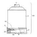
図1に示す回転式エアゾール製品10は、エアゾール製品11と、そのエアゾール製品の底部に取り付けた回転台12とからなる。エアゾール製品11はノズル13を除いて従来の全量噴射型のエアゾール製品と実質的に同じものであり、容器14と、その容器の上部に固定したバルブ15と、バルブのステム16に嵌合させたボタン17とを備えている。なお符号16aはバルブ15の下部に連結したディップチューブである。容器14は手に持って噴射するエアゾール製品に比して高さを低く、径を大きくしている。そのため、床面に載置して回転させながら噴射する場合に安定する。
【0028】
容器14の内部には、原液(有効成分を含む薬液)と噴射剤とからなるエアゾール組成物18が充填されている。有効成分としては、室内や車内などの空間に噴霧するための、あるいは畳、絨毯、床、ソファ、カーテン、車のボディなどに付着させるための殺虫剤、害虫忌避剤、消臭剤、芳香剤、殺菌剤、洗浄剤などがあげられる。噴射剤としては、プロパン、ブタン、およびこれらの混合物などの液化石油ガス、ジメチルエーテル、フロン系液化ガス、およびこれらの混合物などの液化ガスが用いられる。また、加圧剤として、炭酸ガス、チッ素、亜酸化チッ素、圧縮空気などの圧縮ガスを用いてもよい。原液と噴射剤とは前記容器14内に一緒に充填されており、バルブ15を開いて両者が一緒に外部に放出されるときに、バルブ15やステム16内、あるいはノズル13で噴射剤が気化される。そしてそのときに、原液が微粒子状にされ、噴射剤のガスとともに外部に霧状で噴出される。また洗浄剤などの場合、界面活性剤などの発泡剤を含有し、噴出時は霧状で噴出され、付着面で発泡するスプレーフォームとしてもよい。
【0029】
したがって上記の噴射剤の割合が多く、原液の割合が少ない場合は、原液が細かい噴霧粒子になり、一方、噴射剤の割合が少なく、原液の割合が多い場合は噴霧粒子が粗くなる傾向がある。そのため前記作用の欄で説明したように、エアゾール組成物18中の噴射剤の好ましい割合は、25〜90重量%であり、さらに好ましい割合は30〜85%である。
【0030】
前記ボタン17には、斜め上の方向で容器14の半径から偏心した方向を向いているノズル13を有する。図2aに示すように、上から見たノズル13の噴孔13aは、回転中心Oを中心とする円Cの接線方向で、回転方向(矢印N)に対して後方(矢印K)を向いている。そして垂直方向については、図2bに示すように、水平面Hに対する角度θ1 を約60度上向きにしている。なおノズル13の向きは水平面から上向きに−10〜70度とするのが好ましく、前記作用の欄で説明したように、空間噴射する場合の角度θu は約30〜70度とし、床面噴射の場合の角度θd は約−10〜30度とするのが好ましい。
【0031】
ノズル13の噴孔13aの大きさは、通常の空間噴霧あるいは床面噴霧の場合と同程度でよく、たとえば直径0.3〜1.0mm程度が好ましい。すなわち噴孔の直径が0.3mmよりも小さい場合は噴射量が少なくなり、広範囲に拡散させることができない。また、この実施形態のように噴射の反作用で回転させる場合は、反作用が小さく、安定して回転しない。逆に1.0mmより大きい場合は、噴射量が多くなり過ぎ、噴霧粒子の濃度が急激に高くなる。また、噴射の反作用で回転させる場合は、回転速度が速くなり過ぎて、所定の回転数の範囲にすることが困難となるからである。さらにノズル13やバルブ15の形態、エアゾール組成物中の噴射剤の割合および容器14内の圧力によって定まる噴射量は、前記作用の説明のように、7〜30g/10秒とするのが好ましい。
【0032】
図1のエアゾール製品10では、エアゾール組成物18を全量噴射できるように、ボタン17とバルブ15との間には、ボタン17を押し込んだとき、その押し込んだ状態を維持するための従来公知のロック機構が設けられている。そのようなロック機構は、たとえばボタン17に設けた係止片17aと、そのボタンを揺動自在に支持するカバー17bに設けた係合部17cとによって構成しうる。
【0033】
なおこの実施形態では、容器14は、円筒状の胴部19と、その上端に巻き締め部20により固定したドーム21と、胴部19の下端に巻き締め部22により固定した底部23とからなる、いわゆるスリーピース缶である。前記バルブ15はドーム21の上部に形成されているビード部21aにクリンプされている。底部23は中央が上方に湾曲しており、胴部と底部を結合する巻き締め部22は環状を呈し、下方に突出している。さらに巻き締め部22の外周は胴部19とほぼ同径にしており、そのため巻き締め部22のすぐ上は、環状凹部24となっている。
【0034】
前記回転台12は、その巻き締め部22と嵌合するリング状の回転部材31と、回転部材31の下方に配置されるリング状の支持部材32と、両者の間に介在される複数のボール33と、ボール同士の間隔を維持するリテーナ34とからなる。
【0035】
図3bに示すように、回転部材31は筒状の外周壁36と、その外周壁36の内側に突出する円環状の押さえ部37と、その押さえ部37の上面から立ち上がる筒状の突起38とを備えている。外周壁36の上部と、押さえ部37の上面と、突起38とは、図1の容器14の下端の巻き締め部22と嵌合する嵌合溝を形成している。外周壁36の上部の内面には、図1の容器14の環状凹部24と弾力的に係合する係合突起39が突出している。係合突起は39は周方向に連続していてもよく、所定の間隔で並ぶ独立した突起としてもよい。押さえ部37の下面には、ボール33が転動する環状溝40が形成されている。その環状溝40は転動面である。また外周壁36の下部は、ボール33を保護するための外筒36aである。
【0036】
前記支持部材32は、円環状の板体からなる底板44と、その底部の内側に設けられる環状の段部45と、段部の内端から立ち上がる内筒46とを有する。段部45の上面にはボール33が転動する環状溝47が形成されている。底板44の外周は回転部材31の外周壁36より外側に突出している。回転部材31の外周壁36の下端は、回転台12を組み立てた状態で段部45よりも下がっており、外周壁36の内面は、段部45の外周面の外側に隙間を介して面している。さらに支持部材32の内筒46は回転部材31の押さえ部37より上方に延びており、その上端の外面には押さえ部37の上面と隙間を介して係合する爪48が設けられている。爪48は、たとえば図3aに示すように、円周上の4箇所に設けられている。それらの爪48は外面をテーパ面として、回転部材31の内側に挿入し易くしている。
【0037】
前記回転部材31および支持部材32は、合成樹脂や金属などで成形することができる。合成樹脂の場合は軽量で錆の心配がない。また容器14の巻き締め部22と回転部材31の嵌合溝との嵌合が密になる。なお支持部材32の底板44の底面に、すべり止めとして摩擦係数が高いシール49を貼り付けたり、合成樹脂層を設けてもよい。それにより安定して回転することができる。なお、両面接着シートや粘着シートを貼り付けてもよく、その場合は床面などにしっかりと固定しうる。それらの場合は通常は剥離紙を貼着しておく。
【0038】
前記ボール33は通常のボールベアリングに用いる鋼球が好ましいが、他の金属製のボールでもよく、合成樹脂であってもよい。合成樹脂の場合は滑りを安定させるために潤滑剤を合成樹脂に混合するのが好ましい。ボール33の個数は特に限定はない。図3aの場合は8個設けているが、3個以上であればよく、4〜16個程度、とくに6〜12個程度が好ましい。ボール33に代えて、円柱状あるいは円錐台状のローラを用いてローラベアリングの構造としてもよく、また、針状のローラを用いてニードルベアリングのようにしてもよい。
【0039】
前記リテーナ34は図3aに示すように、ボール33が入る部位に貫通孔50を設けた環状の板材であり、金属あるいは合成樹脂などで成形する。図3aの場合は、貫通孔50を設けた部位を補強するため、内側および外側にそれぞれ突出部51を設けて他の部位に比して幅を広くしている。
【0040】
上記の回転台12の回転の摩擦係数は、回転部材31や支持部材32およびボール33の材質や成形精度、嵌合精度、潤滑剤を使用する場合はその潤滑剤の種類などによって異なるが、本実施形態では、ノズル13からエアゾール組成物が噴射したとき、その反作用で回転するときの回転数が35回/分以下で、しかもスムーズに回転するように定める。なお回転数の下限はとくに限定されないが、通常は全量を噴射する前に1回転以上、すなわち360度以上回転するようにする。ただし、トイレの消臭剤や部屋のコーナ部の入口から内部へ噴射する場合(図9参照)など、噴射方向の範囲が制限されている場合は、それ以下であってもよい。
【0041】
また、回転台12以外に、容器14に羽根を付けて空気に対する流体摩擦抵抗を大きくするすることにより(図7参照)、エアゾール製品回転数を抑制することもできる。また容器14の内部にエアゾール組成物の回転を邪魔する部材を設けることにより、エアゾール組成物の回転を抑制して、液面の中央が下がるのを防ぐことができる。ただし内圧を減少させたり、ノズル13の噴孔を小さく絞るなどにより、ノズル13から噴出する噴射速度や噴射量を少なくすることによって回転数を減ずる場合は、噴射粒子の到達距離が遠くに達しないため、好ましくない。すなわち、回転させない状態で噴射させたときの噴霧粒子の到達距離が1〜5m程度となるような噴霧条件を維持しながら、回転を意図的に抑制させるのが好ましい。なお、このように噴射量を減少させることにより回転数を減少させる場合でも、遠心力が減ずるので、容器14の内部の液面(図1の想像線P)の中央部がそれほど低下しない。そのため途中でディップチューブ16aの先端が液面Pから出て、噴射剤だけが抜けるという問題は解消しうる。
【0042】
上記のごとく構成される回転式エアゾール製品10を使用するには、まず室内の床面などの上に置き、図1のボタン17を押し下げる。そうするとボタン17の係合片17aがカバー17bの係合部17cに係合して押した状態を維持し、ノズル13からエアゾール組成物を噴出する。それにより反作用でエアゾール製品11および回転部材31はボール33の列を転動させながら、噴出方向と反対方向に回転し始める。なお図2から分かるように、反作用Fは斜め下向きに働くため、反作用の水平成分(F・cos θ)のみが回転に寄与する。そのため角度θが大きい方が回転速度が遅くなる。他方、垂直成分(F・sin θ)はエアゾール製品10を下向きに押すだけである。したがって回転に寄与せず、むしろ摩擦を増大させて回転を妨げる。エアゾール製品10を回転させようとするトルクは、前記反作用の水平成分と回転中心Oから噴孔13aまでの距離Rとの積により得られる。そしてそのトルクにより、回転が次第に速くなり、回転に対する抵抗とトルクとがバランスした時点でほぼ等速回転となる。したがって距離Rが小さい方が回転速度が遅くなる。
【0043】
そして本実施例でも、回転数は35回/分以下になるように設定されているので、噴孔の移動速度はそれほど速くなく、噴射剤の噴出力は噴霧を遠くまで運ぶために多くが費やされる。それにより噴霧された薬液が遠くまで到達する。しかも噴射孔が回転しながら噴出するので、空間内に広範囲に拡散される。また、容器14内のエアゾール組成物18の液面の中央部がそれほど低くならないので、途中で噴射剤のみが抜けることがなく、最後までほぼ全量を噴射させることができる。
【0044】
他方、回転中はエアゾール製品10の重量は巻き締め部22にかかり、複数のボール33を介して支持部材32によって支持される。そのため安定して回転する。回転に伴って容器14内のエアゾール組成物は重量減少しながら外周方向に移動したり揺れたりするが、広い範囲に分散しているボール33の列により、安定して支持される。
【0045】
エアゾール組成物の残量が少なくなるとエアゾール製品10の重量が少なくなるため、回転に対する摩擦抵抗が減る。しかし液化ガスが連続して噴射されるため、液化ガスの気化が容器内部で繰り返され、容器内部のエアゾール組成物は冷却される。その結果、容器14の内圧が減少していくため、回転はそれほど速くならず、むしろ回転数が減る。そのため、途中で噴射剤のみが抜けることがない。なお上記のように噴射の反作用で回転させる場合は、噴射の開始直後や残量が少なくなったときは回転数が遅いが、本発明における回転数が35回/分以下の条件は、安定して回転しているときに(好ましくは回転の始めから終了まで)満たしている必要がある。
【0046】
図4aに示すボタン17は図1のものとほぼ同じであるが、ノズル13の噴孔13aと回転中心Oとの距離Rが2〜10mmと小さい。そのため噴射力が同程度であっても、エアゾール製品を回転させようとするトルクが小さくなり、回転速度が遅い。なお斜め上向きである点は、図2bと同じである。また、図4bのように噴孔13aと回転中心Oとが離れていても、噴孔13aが外向きになるように角度を付ければ、トルクの腕に相当する距離Raが小さくなるため、実質的に図4aのボタン17と同じく、回転速度を低くすることができる。
【0047】
図4cに示すボタン17は、床面噴霧用のものであり、ノズル13の噴孔13aの水平面Hに対する角度θ1 が小さく、ほぼ水平に近い。このように水平に近い場合は、噴射の反力がそのまま回転させる力になるので、図4aあるいは図4bのように噴孔13aを回転中心Oに近く設定するか、噴孔の向きを外向きにするのが好ましい。
【0048】
図5に示す回転台12は爪48が弾性変形が可能な可撓片60の上端に設けられており、可撓片60は回転部材31の押さえ部37の端部37aに常時弾力的に当接している。可撓片60の数は、4〜12枚程度が好ましい。このものは回転部材31が回転するときは、可撓片60との摩擦に打ち勝ちながら回転することになる。それによって回転速度が遅くなる。すなわち可撓片60は回転部材31に対するブレーキ手段となっている。
【0049】
図6に示す回転台12は、回転部材31の外周壁36の下部の外筒36aの内面に磁石61が埋め込まれており、ボール33は磁石によって引きつけられる鋼球である。そのためボール33はその磁石61により外向きに引かれ、リテーナ34との間に摩擦力が生ずる。そしてその摩擦力により、回転部材31の回転速度が低下する。すなわち磁石61およびボール33はブレーキ手段を構成している。さらにこのものは、回転部材31の回転が速くなるほど、遠心力でボール33が外向きに移動しようとする。そのため磁石による吸着力が加速度的に増大する。そのため回転速度があがるほど、ブレーキ力が増大するので、回転数は低い範囲で安定することになる。
【0050】
図9に示すエアゾール製品11は、容器14の上部、とくにドーム21の周囲に複数枚の羽根63が放射状に取り付けられている。それらの羽根63は容器14が回転するときの空気抵抗を増大させ、回転速度を低下させる。そして空気抵抗は回転数が高くなるほど大きくなる。この羽根63もブレーキ手段となり、エアゾール製品11の回転数を35回/分以下に抑制するのに寄与する。また羽根63の角度を回転方向に対していくらか水平あるいは斜めにする場合は、噴霧されて落下してくる薬液を再度拡散させることができ、空間を長時間処理したい場合などに好適である。
【0051】
図7に示す回転式エアゾール製品65では、回転台12に回転部材31を回転させる駆動機構66が設けられている。このような駆動機構66は、たとえば減速機付きのモータM、減速機の出力軸67に固定されて回転部材31の内面と当接するローラ68などによって構成することができる。なお回転部材31を固定部材32よりも内側に設けて回転させやすくしている。減速機付きのモータMに代えて、ゼンマイや弾み車など、他の回転駆動要素を採用することもできる。この実施形態では、回転力はノズルの噴射の反作用に依らないため、ノズル13を回転中心から偏心させる必要がない。また、場合により、回転する方向に向かって噴孔を向けることもできる。さらに独自の回転駆動要素を備えているので、回転速度を比較的自由に設定しうる。そのため、たとえば容器14の内部のエアゾール組成物の全量を噴射する間に360度、すなわち1回転だけ回転するもの、あるいは2〜3回転だけ回転するものなど、回転数がきわめて少ないものも構成することができる。ただし噴霧の開始時と容器内の残量が少なくなったときとでは、噴射量が異なるため、できるだけ均一に噴霧するには、全量噴射をする間に2回転以上、とくに数回転以上回転させるのが好ましい。
【0052】
この図7の回転式エアゾール製品65では、ボタン17を押すと同時に、あるいはその直後にモータMを回転させ、容器14を回転させながら噴射させて使用する。またタイマーを設けて、スイッチを入れた後、数秒後に回転や噴射を開始させることもできる。また、回転を噴射の反作用で生じさせる場合は、回転を拘束するロック機構を設け、噴射の開始時に同時にタイマーを働かせ、所定時間経過後にロックを解除させるようにしてもよい。また、リモコン操作により、使用者が待避した後、遠隔操作で噴射を開始させたり、回転を開始させたり、回転のロックを解除するようにしてもよい。また、タイマーとモータを組み合わせることにより、始めの5秒間の間に90度以下の角度だけゆっくりと回転させ(回転数で3回/分以下)、その後は普通の35回/分以下の回転数で回転させるようにすることもできる。このようにすると、ノズルが使用者の方に向くまでの間に待避することができるので、使用者に噴霧された薬液がかかったり、吸引したりすることを防ぐことができる。前記タイマーやリモコンは、電気式および機械式のいずれも採用しうるが、モータMを用いる場合は電気式のものが好ましい。なお可燃性の噴射剤を用いるばあいは、電源には電池を用いるのが好ましい。
【0053】
なお前記いずれの回転式エアゾール製品においても、ボタンの押し操作をした後、数秒後に噴射が開始する機構を設けるのが好ましく、それにより使用者が待避する時間をとることができる。そのような機構としては、エアゾール製品の噴射通路(ステム孔から噴射孔の間)に、空気や粘性流体、弾性体などから得られる抵抗により噴射開始を遅らせる従来公知の機構を設けることにより、実現するできる。ただし前述の操作後、5秒間は90度以下の角度だけ回転するエアゾール製品については、操作の開始直後から噴射を始めるようにしてもよい。使用者に噴霧がかからず、噴射を確認してから待避することができるからである。
【0054】
図8は容器14の内部のエアゾール組成物の全量を噴射する間に90度だけ回転する回転式エアゾール製品70を示している。このものは部屋71の扉があるコーナ部に配置して噴射させると、ノズル13の向きが片側の壁72から他方の壁73の間で回転する間にエアゾール組成物をすべて噴射させることができる。また、このものは使用者の方にノズル13が向くことがないので、安心して噴霧させることができ、扉から直ちに待避することができる。
【0055】
また図7の回転式エアゾール製品65において、90度回転するとリミットスイッチが働いてモータMの回転を逆にする回路を設けることもできる。その場合は90度の角度範囲でエアゾール製品11が往復回転運動をするので、図8のように部屋71のコーナー部に設置して使用することができ、しかもその範囲内でほぼ均一に噴霧させることができる。なお、90度以上の角度、たとえば180度〜270度、あるいは90度以下の角度、たとえば30〜60度の範囲で往復回転させるように構成することもできる。
【0056】
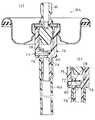
図7のエアゾール製品のように、電気的あるいは機械的な駆動機構により回転させる場合は、噴射させずに回転させることができるが、噴射の反作用を利用する場合は、操作後、気体のみを噴射させて回転させ、回転数が高くなった時点で遠心力の作用で液体を噴霧するようにすることもできる。図10および図11はそのようなエアゾール製品あるいはバルブの実施形態を示している。
【0057】
図10aに示すバルブ15Aは、ハウジング75の下部に中心部から半径方向外側に延びる円筒状の空所76が形成されている。その空所76の端部はベーパータップ77を介してハウジング75の外部と連通しており、上部は連通孔78を介してハウジング75の内部と連通している。そして空所76の下部で、ハウジング75の中心に相当する位置には、ディップチューブ16aと連通する下穴79が形成されている。さらに空所76内には閉塞部材としてボール80が移動自在に収容されている。
【0058】
このバルブ15Aを採用したエアゾール製品では、ステム16を押し下げた噴射開始時、ベーパータップ77から気相部にある液化ガスの気体や圧縮ガスが導入され、導入された気体の勢いによりボール80が中心部に移動し、下穴79を閉鎖する(図10a参照)。それにより気体のみの噴射でエアゾール製品が回転する。そして回転数が上がると、遠心力でボール80が外側に移動する(図10b参照)。それによりベーパータップ77が閉鎖され、下穴79が開放される。それによりエアゾール組成物(液相部)がディップチューブ16aを介してハウジング75内に導入され、霧状の噴射が行われる。
【0059】
このように図10a、図10bのバルブ15Aを備えたエアゾール製品では、噴射の開始時には液相部を噴射せず、気相部にある気体のみを噴射するので、使用者が殺虫剤などを浴びるおそれが少ない。なお、原液と噴射剤とからなるエアゾール組成物に、チッ素ガスや炭酸ガスなどの人体に無害な圧縮ガスを加圧剤として充填しておくのが好ましい。その場合は噴射の開始時にまず加圧剤が噴射されるのでさらに安全である。このものも回転してしばらくしてから、すなわちボール80が外側に移動してからエアゾール組成物が噴射される。
【0060】
図11に示すエアゾール製品81は、ディップチューブ82が、屈伸自在で、かつ屈曲状態に維持できる折り曲げ部83を備えており、先端に重り84を設けている。そして使用の開始前には、実線で示すように、ディップチューブ82の先端を気相部85に出した状態で維持させている。このような折り曲げ部83は、たとえば蛇腹状に形成し、強く曲げるなどにより実現しうる。なお、弱いバネ片などで折り曲げた形状を維持するようにしてもよい。
【0061】
このものは最初はディップチューブ82の先端が気相部85と連通しているので、ステム16を押し下げると、まず気体のみがディップチューブ82から噴出され、バルブ15およびステム16を介して外部に噴出する。それによって噴射の反作用で容器が回転を開始する。回転数がある程度高くなると、重り84に生ずる遠心力で、想像線で示すように、ディップチューブ82の先端が液相部86に入る。それによりエアゾール組成物がディップチューブ82の先端から吸い込まれ、ステム16を介して外部に噴出される。
【0062】
図1などの実施形態ではノズルあるいは噴孔が1本あるいは1個である。しかしノズルの本数や噴孔の個数はそれらに制限されず、複数本あるいは複数個設けることができる。ただし複数設ける場合は、回転中心まわりに軸対称に配置するのが好ましい。このように軸対称に設けると、偏心している噴孔から噴射されるエアゾール組成物の反作用力の内、平行移動の成分が互いに相殺し、回転させようとする成分のみが残る。そのため、一層安定して回転し、転倒したり、一方向に移動するおそれが少ない。
【0063】
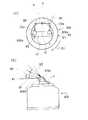
図12aおよび図12bに示す回転式エアゾール製品88は、ボタン17が容器14に対して垂直方向の軸心(回転中心)Oまわりに回転自在に設けられている。ボタン17は横に長く、ボタン17の同じ側に、回転中心OからそれぞれRだけ離れた位置に噴孔13aを備えたノズル89a、89bが設けられている。ただし図12bに示すように、第1のノズル89aの噴孔13aは水平面に対してある角度θ1 だけ上を向いており、第2のノズル89bの噴孔13bは水平面に対してそれより大きい角度θ2 だけ上を向いている。そのため、第1のノズル89aからの噴射による反作用の水平方向の成分V1はf・cosθ1 であり、第2のノズル89bからの噴射による反作用の水平方向の成分V2はf・cosθ2 である。そのためボタン17は、両者の差(f・cosθ1 −f・cosθ2 )に基づいて、時計方向(矢印S1方向)にゆっくりと回転する。
【0064】
すなわち片方のノズルだけであれば、噴射による反作用の水平方向成分と、回転中心Oから噴孔までの距離Rの関がトルクとして作用するが、この実施形態では両方のノズルのトルクが逆方向に働くため、両者の差だけが回転させるために寄与する。そのため回転速度は小さく、噴射される薬液は噴孔から遠くまで達する。また、第1のノズル89aからの噴射物B1は従来のものと同じく、進行方向に対して後方に噴射されるが、第2のノズル89bからの噴射物B2は、進行方向に向かって前側に噴射されることになるので、噴射距離が一層長くなる。また、両方のノズル89a、89bからの噴射量は、1個のノズルの2倍であるから、噴射量自体が多い。なお、回転速度によって変わるが、第1のノズル89aからの噴射物B1は低い角度で噴射されるので、遠くまで達し、第2のノズル89bからの噴射物B2は高い角度で噴射されるので、上の方まで達し、かつ水平距離は短い。このように2個のノズル89a、89bからの噴射は、たがいに補って、部屋内に広い範囲で噴射することができる。
【0065】
なお図12の場合は、2個のノズル89a、89bの水平方向の角度を変えることにより、トルクに寄与する反作用の大きさを左右で変えているが、ノズルの噴孔の内径を変えるなど、他の方法によって左右の反作用に差を与えることもできる。たとえば図13aに示す回転式エアゾール製品90は、第1ノズル89aと第2ノズル89bの噴孔の大きさ、水平方向に対する角度は同じであるが、回転中心Oからの距離R1、R2が異なる。この場合も噴射の反作用に基づくトルク(f×R)が異なるので、両者の差に基づいてゆっくりと矢印S1方向に回転する。また図13bの回転式エアゾール製品90の場合は、回転中心Oからの距離Rは同じで、水平面に対する角度も同じであるが、噴孔と回転中心を結ぶ線に対する噴孔の水平方向の角度θ3、θ4が異なる。そのため、実質的な回転中心Oからの距離R、R2が異なり、両者のトルクに差が生ずる。それによって両者の差に基づいて、矢印S1方向にゆっくりと回転する。
【0066】
図12および図13a、図13bの実施形態では、ボタン17の同じ側に噴孔を設けているので、使用者は噴孔を使用者と反対側に向けた状態で噴射を開始させ、噴孔が使用者側に回転してくる前に、待避することができる利点がある。しかしタイマー式など、使用者が逃げる時間が充分にある場合は、図13cに示すように、ボタン17の互いに反対側に2個のノズル89a、89bを設けることができる。その場合も、噴孔の水平方向の角度を変えたり、垂直方向の角度を変えたり、あるいは回転中心からの距離を変えることにより、噴射の反作用に基づくトルクに差を設ければ、それらの差によってゆっくりとボタン17を回転させることができる。
【0067】
なお、前述の実施形態では、ボタン17を回転自在とし、そのボタン17に2個のノズル89a、89bを設けているが、図1の回転式エアゾール製品10のように、ボタン17を容器14に対して回転させず、エアゾール製品11ごと回転させるようにしても同じ作用効果を奏する。さらに噴射の反作用を利用せずに、別個にモータなどの回転駆動機構を設ける場合でも、回転方向に対して後ろ向きの第1のノズルと、前向きの第2のノズルを設ける場合は、前後のノズルからの噴射の空気に対する相対速度に差が生ずるので、噴孔からの到達距離に差が生ずる。それによって、第1のノズルからの噴射物はエアゾール製品から近い円環状の範囲に薬液を散布し、第2のノズルからの噴射物が遠い円環状の範囲に薬液を散布する。したがって薬液を散布する範囲の全体が拡がる。それらの場合も、第1のノズルの噴孔の水平方向あるいは垂直方向の角度と、第2のノズルの水平方向あるいは垂直方向の角度を変えて、各ノズルが担当する噴霧範囲を異ならせるようにすることができる。それにより、一層、部屋の中の広い範囲に薬液を散布することができる。
【0068】
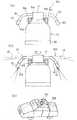
図14aに示す回転式エアゾール製品90は、ボタン17の上端に、可撓性および弾力性を有するチューブ91の一端を取り付けており、そのチューブ91の自由端に噴霧用のノズル13を取り付けている。またチューブ91とステム16とはボタン17の内部で連通している。さらにチューブ91の先端近辺には、重り92が取り付けられている。また図14bに示すように、チューブ91に対して回転方向の反作用を与えるべく、チューブ91は重り92の下部の近辺の符号93の位置で、いくらか横向きに角度θ5だけ屈曲されている。記チューブ91はたとえば合成樹脂製のものが用いられる。また弾力性を強くするため、チューブの内部にバネ鋼製の線材を埋め込んでもよい。その線材は真っ直ぐであってもよく、また、コイル状に巻かれていてもよい。
【0069】
さらにこの実施形態では、ボタン17に噴射状態に維持する突起94を設けると共に、容器14の肩部に肩カバー95を取り付け、その肩カバー95に突起94と係合する段部96を形成している。そのため、ボタン17を押し込んでいくから回動させると、突起94が段部96と係合して噴射状態を維持する。なお容器14の底部には回転台12を取り付けている。
【0070】
このものは回転の初期にはチューブ91はその弾力性により、ほぼ真っ直ぐ上に向かって延びており、噴孔からの噴射の反作用はほぼ下向きに働く。そのため噴射に基づくトルクは小さい。そのためノズル13は下向きにいくらか屈曲しながらゆっくりと回転する。そして回転し始めると、ノズル13および重り92に加わる遠心力で、想像線のように根元部91aから外向きに撓んでくる。そのため、ノズル13の回転中心Oからの距離Rがしだいに増加し、同時に噴孔の向きも水平に近づいていく。それにより一層、反作用に基づく回転させるトルクが増加し、さらに傾きが大きくなっていく。このようにこの回転式エアゾール製品90では、噴射の初期には速度が遅く、上向きに噴射し、噴射が進むにつれて回転速度が速く、横向きに噴射していく。したがって回転式エアゾール製品90の上方から部屋の遠い位置まで、広く薬液を散布することができる。
【0071】
なお、このものも図13cのようにチューブの両側にノズル89a、89bを設け、両者のトルクの差で回転させるようにしてもよい。さらに図1のような回転台12とエアゾール製品11とを組み合わせた回転式エアゾール製品や、モータなどの別個の回転駆動機構を備えた回転式エアゾール製品にも適用することができる。なお、前記実施形態では重り92を用いているが、チューブ91の弾力性が弱い場合は、ノズル13自体の重量あるいはチューブ91自体の重量でも、ほぼ同様の作用を奏することができる。その場合は、重り92を省略することができる。
【0072】
図14aに示す回転式エアゾール製品90は、チューブ91の可撓性により根元部91aから撓むようにしているが、図14cに示すように、チューブ91自体は剛性を有する金属パイプなどとし、その根元部とボタン17とを可撓性を有する連結チューブ97で連結するようにしてもよい。その場合は、コイルバネ95などで、チューブ91の根元部を真っ直ぐ上向きに戻るように付勢するのが好ましい。この場合、回転速度が遅くなってくるとチューブ91は再び上向きに戻る。すなわち噴射開始直後は上向きから水平方向にノズル13が移動し、さらに容器14内のエアゾール組成物が少なくなり、回転が遅くなると、ノズル13は水平から上向きに戻る往復運動を行う。そのため薬液を広範囲に散布することができる。なお連結チューブ97に代えて、ロータリジョイントでチューブ91を回転自在に連結することもできる。さらに金属と合成樹脂のように、チューブ91とチューブを連結する部材とを異なる材質で構成することにより、チューブ91自体を部材に対して回転させることもできる。
【0073】
図15aに示すエアゾール製品90はチューブ91を2本、ボタン17に対して横向きに、180度離れた位置に取り付けている以外は、図14aのものと実質的に同じである。チューブ91の先端には重りを兼ねるノズル13が設けられている。また、突起94および肩カバー95についても、図14aの場合と同じである。各ノズル13の噴孔13aは、エアゾール製品11を同じ方向にトルクを与える向きに設けてもよく、逆向きのトルクを与える向きに設けてもよい。後者の場合は、その噴射の反作用の差で回転させるべく、噴射力に差を与えるようにする。
【0074】
この回転式エアゾール製品90では、回転していない状態ではチューブ91は途中から下向きに湾曲している。そして図15bに示すようにボタン17を押していくらか回動させ、突起94を肩カバー95の段部96に係合させて噴射させると、噴孔13aからの噴射の反作用で、あるいは反作用の差で、回転台12の上のエアゾール容器11全体が回転を始める。そして初期にはノズル13の噴孔13aが斜め下側を向いており、回転式エアゾール製品90の比較的近くに薬液を散布する。そして回転が速くなると、遠心力により両方のチューブ91が延び、そのため噴孔13aが横方向を向くようになる。そのため噴孔13aから噴射される薬液は遠くの方まで到達するようになる。
【0075】
また、残量が少なくなって内圧が低下すると、回転が遅くなる。このようにこの回転式エアゾール製品90では、チューブ91が下を向いたり横方向に伸びたりすることにより、回転式エアゾール製品90が置かれている場所の近くから遠くまで、まんべんなく薬液を散布することができる。そのため絨毯や床などを処理する薬剤、たとえば殺虫剤や消臭剤を散布するために使用したり、自動車のボディに洗浄剤を散布するために使用することができる。自動車のボディに洗浄剤を散布する場合は、たとえば図15cに示すように、上記の回転式エアゾール製品90を自動車98の屋根に乗せた状態で、エアゾール製品を回転させながら内容物を噴射させるようにする。それによりボディの表面の全体に洗浄剤を散布することができる。
【0076】
前記実施形態では、エアゾール製品として全量噴射型のものを示しているが、本発明の回転式エアゾール製品はそれに限らず、たとえば、一時的に車内やトイレに消臭剤を噴霧するものなど、定量噴射型あるいは一定時間噴射型のものなどにも採用しうる。
【0077】
【実験例】
つぎに実験例をあげて本発明の回転式エアゾール製品の効果を説明する。下記の表1の2種類のエアゾール組成物を、満注量が180mlのブリキ製のスリーピース缶(全水準共通)と表2のバルブおよびボタンを備えた2種類のエアゾール容器に充填して4種類のエアゾール製品を製造した。
【0078】
【表1】
【表2】
上記の各エアゾール製品を回転台に固定し、表3に示す回転数で回転させながら噴射させ、そのときの空間での拡散性および床面への付着性を調べた。その結果を表3に合わせて示す。なお、試験は図16に示すような広さが4m×4m、高さが2.5mの部屋にて、部屋の中心部に回転台およびエアゾール製品11を置いて行った。部屋内は無風状態とした。
【0081】
【表3】
[評価方法] 図16に示す部屋の中央にエアゾール製品を設置し、製品から水平距離1m、1.5m、2mで、高さ0m、1.5m、2mの場所にエタノールと反応する紙を置き、噴射完了後反応の有無を確認した。
【0083】
空間での拡散性
製品からの水平距離1m、1.5m、2m、高さ1m、1.5m、2mの場所で反応の有無を確認した。試験結果の評価は次の通りである。
◎:すべての場所で反応が認められた。
○:水平距離1.5m、高さ1.5m以内での反応が確認された。
△:水平距離1m、高さ1mの場所のみで反応が確認された。
×:反応確認できず。
【0084】
床面での付着
製品からの水平距離1m、1.5m、2m、高さ0mの場所で反応の有無を確認した。試験結果の評価は次の通りである。
◎:すべての場所で反応が認められた。
○:水平距離1mおよび1.5mの場所で反応を確認した。
△:水平距離1mの場所でのみ反応を確認した。
×:反応確認できず。
【0085】
上記の結果から回転数が35回/分以下であれば、空間噴霧および床面付着のいずれの場合も「○」以上の評価であり、比較的広い範囲に拡散されていることが分かる。さらに30回/分以下であれば、ほとんどの場合で「◎」の評価であり、広い範囲に拡散されていることが分かる。とくに10回/分の場合は、すべてについて「◎」であり、回転速度を遅くする方が拡散範囲が広がることが分かる。また他方、回転数が40回/分の場合は、ほとんど「△」か「×」であり、充分に遠くまで拡散されないことが分かる。
【図面の簡単な説明】
【図1】本発明の範囲外の回転式エアゾール製品の形態を示す一部断面正面図である。
【図2】図2aおよび図2bは図1におけるノズルの角度を示す平面図および側面図である。
【図3】図3aおよび図3bは図1における回転台の一部切り欠き要部平面図および縦断面図である。
【図4】図4aおよび図4bはそれぞれ本発明の範囲外の形態を示す平面図であり、図4cは本発明の範囲外の形態を示す側面図である。
【図5】本発明にかかわる回転台の他の実施形態を示す要部断面図である。
【図6】本発明にかかわる回転台のさらに他の実施形態を示す要部断面図である。
【図7】本発明の範囲外の回転式エアゾール製品の形態を示す要部正面図である。
【図8】本発明の範囲外の回転式エアゾール製品の形態を示す一部切り欠き正面図である。
【図9】本発明の範囲外の回転式エアゾール製品の形態の作動状態を示す概略平面図である。
【図10】図10aは本発明のエアゾール製品に用いるバルブの一実施形態を示す断面図、図10bはその作動状態を示す要部断面図である。
【図11】本発明のエアゾール製品に用いるディップチューブの一実施形態を示す断面図である。
【図12】図12aおよび図12bはそれぞれ本発明のエアゾール製品の一実施形態を示す平面図および側面図である。
【図13】図13a〜cはそれぞれ本発明のエアゾール製品の他の実施形態を示す平面図である。
【図14】図14aおよび図14bはそれぞれ本発明の範囲外のエアゾール製品の形態を示す側面図および平面図、図14cは本発明の範囲外のエアゾール製品の形態を示す要部断面図である。
【図15】図15aは本発明の範囲外のエアゾール製品の形態を示す一部断面側面図、図15bはそのエアゾール製品の使用状態を示す一部断面側面図、図15cはそのエアゾール製品の使用対象と共に示す斜視図である。
【図16】本発明の回転式エアゾール製品の実施例の効果の測定方法を示す斜視図である。
【図17】従来の回転式エアゾール製品の使用状態を示す断面図である。
【符号の説明】
10 回転式エアゾール製品
11 エアゾール製品
12 回転台
13 ノズル
13a 噴孔
14 容器
15 バルブ
16 ステム
16a ディップチューブ
17 ボタン
17a 係止片
17b カバー
17c 係合片
18 エアゾール組成物
19 胴部
20 巻き締め部
21 ドーム
21a ビード部
22 巻き締め部
23 底部
24 環状凹部
31 回転部材
32 支持部材
33 ボール
34 リテーナ
36 外周壁
36a 外筒
37 押さえ部
38 突起
39 係合突起
40 環状溝
44 底板
45 段部
46 内筒
47 環状
48 爪
49 シール
50 貫通孔
51 突出部
60 可撓片
61 磁石
63 羽根
65 回転式エアゾール製品
66 駆動機構
M モータ
67 出力軸
68 ローラ
70 回転式エアゾール製品
71 部屋
72、73 壁
15A バルブ
75 ハウジング
76 空所
77 ベーパータップ
78 連通孔
79 下穴
80 ボール
81 エアゾール製品
82 ディップチューブ
83 折り曲げ部
84 重り
85 気相部
86 液相部
88 回転式エアゾール製品
89a 第1のノズル
89b 第2のノズル
S1 回転方向
90 回転式エアゾール製品
91 チューブ
92 重り
93 下部近辺の位置
94 突起
95 肩カバー
96 段部
97 連結チューブ
98 自動車[0001]
BACKGROUND OF THE INVENTION
The present invention relates to a rotating aerosol product. More specifically, the present invention relates to a rotary aerosol product having excellent spraying performance such that spray particles diffuse in a wide range in the space or adhere to a wide range on the floor surface.
[0002]
[Prior art]
2. Description of the Related Art Conventionally, aerosol products such as insecticides and fragrances that treat indoor and in-car spaces and floor surfaces such as tatami mats and carpets have been used. Since these aerosol products have a wide range of objects to be sprayed, it is necessary to diffuse spray particles over a wide range. Therefore, a so-called full-injection type aerosol product is used in which the user does not spray the product by hand and places it on the floor or the like and injects the entire amount while the user is retracting. In order to further expand the injection range, the aerosol product is rotated by the reaction of the injection, as in, for example, Japanese Utility Model Publication No. 56-11962, Japanese Utility Model Publication No. 5-3241, Japanese Utility Model Application Publication No. 5-5973, Japanese Utility Computer Application Publication No. 5-34779. Have been proposed for spraying over a wide area.
[0003]
[Problems to be solved by the invention]
In the conventional rotary aerosol product, since the entire aerosol product is automatically rotated by the reaction of injection, the aerosol product is spread around 360 ° around the aerosol product. Therefore, there is an advantage of injecting in a wide range as compared with a stationary aerosol product that injects upward or obliquely upward. However, in such a rotary aerosol product, the rotation is not smooth from the middle, and in some cases, the injection itself may stop before the entire amount is injected, even though the contents remain. In addition, even when it is rotating smoothly, it has been noticed that the spray does not reach far as compared with the case of spraying without rotating. That is, in the rotary aerosol product, the spraying concentration is high in the vicinity of the aerosol product, and the concentration rapidly decreases as the distance from the aerosol product increases.
[0004]
As a result of improving the bearing mechanism that supports the aerosol product in order to solve the incomplete rotation state seen in such a rotary aerosol product and the problem that the injection stops in the middle, the present inventor has developed an aerosol product that rotates more smoothly. I was able to develop it. However, when the remaining amount of the contents still decreased, the problem that the rotation was not smooth or the injection stopped halfway was not solved, but rather a tendency to become worse was recognized. Furthermore, it has been noticed that the spraying distance tends to become shorter as the rotation becomes smoother.
[0005]
In view of the above problems, the present invention has as its first technical object to provide an aerosol product that can be smoothly rotated to the end and can be sprayed to the end as much as possible. Furthermore, this invention makes it the 2nd technical subject to provide the rotary aerosol product which lengthens the reach | attainment of a spray and can thereby inject it more widely.
[0006]
[Study on issues]
As a result of carrying out experiments and investigations on the reason why rotation and injection are not smooth in the middle of a rotating aerosol product, in a rotating aerosol product, as shown in FIG. It moved to the outer side of the
[0007]
Also, the reason why the spray reach distance is shortened is not clear, but when spraying while the nozzle hole recedes, such as an aerosol product that rotates due to the reaction of injection, even if the injection speed from the nozzle hole is constant, The speed will be relatively low and will therefore not reach far. In other words, active ingredients that are harmful to the human body such as insecticides may be sucked by humans if they are drifting in the space for a long time. It is supposed to fall on the floor or adhere to a wall or the like, but if the relative speed is slow, it will fall to the floor before reaching far. Moreover, since the direction of the nozzle hole continuously changes with rotation, it is considered that the air flow due to the jet does not reach far.
[0008]
Based on the above hypothesis, the present inventor has conducted an experiment in which the rotational speed is intentionally reduced to inject, and when rotating at a certain rotational speed or less, the centrifugal force is suppressed and the stock solution is smoothed to the end. The present invention has been completed by finding out that it can be sucked into the water and at the same time the fact that the spray reaches far.
[0009]
An aerosol product of the present invention (Claim 1) is an aerosol product of a type in which a part or most of a container including a nozzle hole rotates around a vertical axis and spraying continues during rotation. ,A first nozzle hole for rotating a part or most of the container in one direction with respect to the center of rotation, and a second nozzle hole for rotating in the opposite direction, a part or most of the container ofRotation speed is 35 times / min or lessThe difference between the torque based on the reaction of the injection from the first nozzle hole and the reaction of the injection from the second nozzle hole isIt is characterized by that. The number of rotations is preferably 30 times / minute or less. In this aerosol product,The difference in torque based on the reaction of the injection is the difference in the horizontal angle of the injection hole, the difference in the vertical angle of the injection hole, the difference in the distance from the rotation center of the injection hole, or the difference in the inner diameter of the injection hole. Is preferably based on (Claim 2). Also, the first and secondThe direction of the nozzle hole is preferably -10 to 70 degrees upward with respect to the horizontal plane.(Claim 3). That is, in the case of space spray, it is preferably 30 to 70 degrees upward with respect to the horizontal plane, and in the case of floor spray, it is preferably -10 to 30 degrees upward with respect to the horizontal plane. further,Of the first and second nozzle holesThe injection amount is preferably 7 to 30 g / 10 seconds.(Claim 4).
[0010]
The proportion of the propellant in the aerosol composition is preferably 25 to 90% by weight.(Claim 5)30 to 85% by weight is more preferable.. MaIn addition, it is preferable that it rotates 45 to 720 degrees from the start of injection until the entire amount is injected (Claim 6), and preferably rotates 45 to 90 degrees depending on the application. Further, it is preferable that injection or rotation starts after a predetermined time has elapsed since the operation. Otherwise, it is preferable that it takes 5 seconds or more to rotate 90 degrees from the operation (Claim 8)..
[0011]
Immediately after operationThe valve and the gas phase part in the container are in communication with each other.Inject only gas,Rotational speed increased due to gas injectionAfter a predetermined time, The valve and the liquid phase part in the container communicate with each other.Those that start spraying of chemicals are preferred (Claim 9). Such aerosol products areThe aerosol product valve has a dip tube that communicates the inside of the valve and the liquid phase part in the container, and a vapor tap that communicates the inside of the valve and the gas phase part in the container,A closing member provided movably between a position for closing the pilot hole communicating with the dip tube and a position for closing the vapor tap farther than the position for closing the pilot hole with respect to the rotation center.Immediately after the operation, the gas in the gas phase portion is introduced into the valve from the vapor tap, the closing member closes the pilot hole by the force of the introduced gas, and the rotational speed is increased by jetting only the gas. In addition, it is preferable that after the elapse of a predetermined time, the closing member moves to a position where the vapor tap is closed by the centrifugal force generated in the closing member. Further, the aerosol product valve has a dip tube that communicates the inside of the valve with the inside of the container, the dip tube includes a bent portion that can be bent and stretched and can be maintained in a bent state, and has a weight at the tip. Immediately after the operation, the bent part of the dip tube is bent so that the tip of the dip tube communicates with the gas phase part in the container, and after a predetermined time has elapsed when the rotational speed has increased by jetting only gas, It is preferable that the bent portion of the dip tube extends so that the tip of the dip tube communicates with the liquid phase portion in the container by centrifugal force generated in the weight.
[0014]
Since the aerosol product of the present invention (Claim 1) has a rotational speed of 35 / min or less, there is almost no decrease in the central portion of the liquid surface of the aerosol composition in the container. Therefore, an aerosol product using a dip tube is used. In this case, the suction port does not come out almost above the liquid surface during the injection, and only the propellant is not injected. Furthermore, even when the injection hole moves in the direction opposite to the injection direction, the relative velocity of the injected spray particles to the air does not decrease so much, and the spray reach is about 70 to 98% when the aerosol product is not rotated. It is. Therefore, it is possible to spray far enough. Further, when the rotational speed is 30 / min or less, the liquid level is further reduced, and the spray particles reach a longer distance, and can be diffused widely in the room.
A first nozzle hole that rotates the container in one direction with respect to the center of rotation; and a second nozzle hole that rotates the container in the opposite direction. Since the reaction is performed by the difference between the reaction and the reaction of the injection from the second nozzle hole, the rotation speed can be reduced while maintaining a large amount of injection. Furthermore, since one nozzle hole is jetted while moving forward, the chemical solution reaches farther. In addition, since the distances of the chemicals ejected from both the nozzle holes are different, they can be widely distributed from a range close to the container to a range far from the container. Note that when the injection amount from one nozzle hole decreases, the injection amount from the other nozzle hole also decreases at the same time, so that the speed is gradually reduced as a whole in balance between both.
[0015]
1st, 2ndWhen the direction of the nozzle hole is -10 to 70 degrees upward with respect to the horizontal plane (Claim 3) Can be diffused widely from the top to the far of the aerosol product in the indoor space or floor. That is, when the angle is lower than -10 degrees (downward), it can be spread only on a narrow floor near the aerosol product, and when it exceeds 70 degrees, it diffuses only above the aerosol product and distant Will not reach. In addition, since it can be spread | diffused widely in indoor space etc. when it is set as the range of 30-70 degree | times, it is suitable for space spray. That is, when the angle is lower than 30 degrees, the diffusion is large near the floor surface, and the diffusion in the space is reduced. On the other hand, when the direction of the nozzle hole is set to -10 to 30 degrees with respect to the horizontal plane, it is suitable for floor spraying because it can be widely adhered to the floor surface without being diffused to a high position. That is, if it exceeds 30 degrees, it will adhere to a high position uselessly.
[0016]
Of the first and second nozzle holesWhen the injection amount is 7 to 30 g / 10 seconds (Claim 4) Can reach far enough, and the concentration of the propellant in the space does not increase rapidly. That is, when it is less than 7 g / 10 seconds, it does not reach far enough, and when it is rotated by the reaction of injection, it does not rotate sufficiently. Conversely, if it exceeds 30 g / 10 seconds, the concentration of the propellant in the space becomes too high, which is dangerous. Moreover, since the reaction of injection becomes large, the product is difficult to rotate stably.
[0017]
When the proportion of the propellant in the aerosol composition is 25 to 90% by weight (Claim 5) Has a moderate average particle size of spray particles, diffuses over a wide range, and reaches far away. That is, when the amount is less than 25% by weight, the spray particles become coarse, so that the particles are easily dropped as liquid particles, and the injection speed is slow, so that they do not diffuse over a wide range. Moreover, when rotating by the reaction of injection, since the amount of the propellant is too small, it is difficult to inject the entire amount while rotating. Conversely, if the proportion of the propellant exceeds 90%, the spray particles become too fine and do not reach far away. Moreover, since the momentum of injection is strong, when rotating by reaction, it becomes difficult to suppress rotation speed to 35 times / minute or less. Furthermore, when the proportion of the propellant is 30 to 85% by weight, there is an advantage that the propellant diffuses over a wider range and reaches far away.
[0019]
In the aerosol product that rotates 45 to 720 degrees from the start of injection to the injection of the entire amount (Claim 6), there is almost no adverse effect due to rotation, and it can be sufficiently diffused in the desired range. Also, when injection is completed at an angle of 360 degrees or less, especially 45 to 90 degrees, for example, when it is placed in the corner of a room, useless injection is avoided when the range to be sprayed is limited. There are advantages you can do. Further, when the injection or rotation starts after a predetermined time has elapsed from the operation (claim 7), the user can evacuate until the operated user starts the injection or rotation. For this reason, there is little possibility that the sprayed chemical solution is applied to the user or the sprayed chemical solution is sucked.
[0020]
Further, even if rotation and injection start immediately after the operation, those that require 5 seconds or more to rotate 90 degrees after the operation (Claim 8) are in a state where the injection hole is directed to the opposite side to the user. It is possible to confirm the injection by operating at. Moreover, since it is not suitable for the user for more than 5 seconds, there is room for the user to save, and the sprayed chemical solution is prevented from being applied to the user or sucked..
[0021]
Immediately after operationThe valve and the gas phase part in the container are in communication with each other.Inject only gas,Rotational speed increased due to gas injectionAfter a predetermined time, The valve and the liquid phase part in the container communicate with each other.Those that start spraying chemicals(Claim 9)If the user evacuates while injecting the gas, there is no possibility of sucking a chemical solution containing an active ingredient such as an insecticide.AndWhen the rotational speed is low, only gas is ejected through the valve, and when the rotational speed is increased, the liquid phase part (chemical solution and liquefied gas) is ejected through the valve.
The aerosol product valve has a dip tube that communicates the inside of the valve and the liquid phase part in the container, and a vapor tap that communicates the inside of the valve and the gas phase part in the container,A closing member provided movably between a position for closing the pilot hole communicating with the dip tube and a position for closing the vapor tap farther than the position for closing the pilot hole with respect to the rotation center.Immediately after the operation, the gas in the gas phase portion is introduced into the valve from the vapor tap, the closing member closes the pilot hole by the force of the introduced gas, and the rotational speed is increased by jetting only the gas. The aerosol product moves to a position where the closing member closes the vapor tap by the centrifugal force generated in the closing member after a predetermined time has passed (
[0026]
DETAILED DESCRIPTION OF THE INVENTION
Next, an embodiment of the aerosol product of the present invention will be described with reference to the drawings. FIG. 1 illustrates the present invention.Out of range2a and 2b are a plan view and a side view showing the angle of the nozzle in FIG. 1, and FIGS. 3a and 3b are a plan view of a part of the rotary table in FIG. The longitudinal sectional views, FIG. 4a and FIG.Out of rangeFIG. 4c is a plan view showing the form of the present invention.Out of rangeFIG. 5 and FIG. 6 are main part sectional views showing other embodiments of a turntable according to the present invention, and FIG.Out of rangeThe principal part front view which shows a form, FIG. 8 is the present invention.Out of rangeFIG. 9 is a partially cutaway front view showing the form of the present invention.Out of rangeFig. 10a is a cross-sectional view showing an embodiment of a valve used in the aerosol product of the present invention, Fig. 10b is a cross-sectional view of the main part showing the operating state, and Fig. 11 is a cross-sectional view of the present invention.One embodiment of dip tube used in aerosol productFIGS. 12a and 12b are sectional views showing the aerosol product of the present invention.One embodimentFIGS. 13a to 13c are plan views showing still other embodiments of the aerosol product of the present invention, and FIGS.Out of rangeA side view and a plan view showing the form, FIG.Out of rangeFig. 15a is a cross-sectional view of the main part showing the form,Out of rangeFIG. 15b is a partial cross-sectional side view showing the use state of the aerosol product, FIG. 15c is a perspective view showing the use object of the aerosol product, and FIG. 16 is an implementation of the aerosol product of the present invention. It is a perspective view which shows the measuring method of the effect of an example.
[0027]
A
[0028]
The
[0029]
Therefore, when the proportion of the propellant is large and the proportion of the stock solution is small, the stock solution becomes fine spray particles, whereas when the proportion of the propellant is small and the proportion of the stock solution is large, the spray particles tend to be coarse. . Therefore, as explained in the above-mentioned column of action, the preferable ratio of the propellant in the
[0030]
The
[0031]
The size of the
[0032]
In the
[0033]
In this embodiment, the
[0034]
The
[0035]
As shown in FIG. 3 b, the rotating
[0036]
The
[0037]
The rotating
[0038]
The
[0039]
As shown in FIG. 3a, the
[0040]
The friction coefficient of the rotation of the rotary table 12 varies depending on the material of the rotating
[0041]
In addition to the
[0042]
In order to use the
[0043]
Also in this embodiment, since the rotational speed is set to be 35 times / minute or less, the moving speed of the nozzle hole is not so fast, and the spray output of the propellant is mostly consumed to carry the spray far. It is. Thereby, the sprayed chemical reaches far. Moreover, since the injection holes are ejected while rotating, they are diffused widely in the space. Moreover, since the center part of the liquid level of the
[0044]
On the other hand, during rotation, the weight of the
[0045]
When the remaining amount of the aerosol composition is reduced, the weight of the
[0046]
The
[0047]
The
[0048]
The rotary table 12 shown in FIG. 5 is provided at the upper end of a
[0049]
In the
[0050]
FIG.The
[0051]
FIG.In the
[0052]
thisFIG.In the
[0053]
In any of the above-mentioned rotary aerosol products, it is preferable to provide a mechanism for starting the injection after a few seconds after the button is pressed, thereby allowing time for the user to escape. Such a mechanism is realized by providing a conventionally known mechanism that delays the start of injection by resistance obtained from air, viscous fluid, elastic body, etc. in the injection passage (between the stem hole and the injection hole) of the aerosol product. I can do it. However, for an aerosol product that rotates by an angle of 90 degrees or less for 5 seconds after the aforementioned operation, injection may be started immediately after the start of the operation. This is because the user does not spray and can evacuate after confirming the injection.
[0054]
FIG.Shows a
[0055]
AlsoFIG.In the
[0056]
FIG.In the case of rotating by an electrical or mechanical drive mechanism such as aerosol products, it can be rotated without jetting, but when using the reaction of jetting, only gas is jetted after operation. The liquid can be sprayed by the action of centrifugal force when the rotation speed is increased. Figures 10 and 11 show embodiments of such aerosol products or valves.
[0057]
In the
[0058]
In the aerosol product adopting this valve 15A, at the start of injection when the
[0059]
Thus, in the aerosol product provided with the valve 15A of FIG. 10a and FIG. 10b, the liquid phase part is not injected at the start of injection, and only the gas in the gas phase part is injected, so the user is exposed to an insecticide or the like. There is little fear. In addition, it is preferable to fill the aerosol composition consisting of the stock solution and the propellant as a pressurizing agent with a compressed gas that is harmless to the human body such as nitrogen gas or carbon dioxide gas. In that case, since the pressurizing agent is first injected at the start of injection, it is safer. The aerosol composition is sprayed after a while after this rotation, that is, after the
[0060]
An
[0061]
Since the tip of the
[0062]
In the embodiment such as FIG. 1, the number of nozzles or nozzle holes is one or one. However, the number of nozzles and the number of nozzle holes are not limited thereto, and a plurality of nozzles or a plurality of nozzle holes can be provided. However, when providing a plurality, it is preferable to arrange them symmetrically about the center of rotation. When provided symmetrically in this way, the components of the parallel movement cancel each other out of the reaction force of the aerosol composition injected from the eccentric nozzle hole, and only the component to be rotated remains. Therefore, there is little risk of rotating more stably, falling over, or moving in one direction.
[0063]
In the
[0064]
That is, if only one nozzle is used, the relationship between the horizontal component of the reaction caused by the injection and the distance R from the rotation center O to the nozzle hole acts as torque. In this embodiment, the torque of both nozzles is in the opposite direction. Because it works, only the difference between the two contributes to rotation. Therefore, the rotation speed is small, and the injected chemical reaches far from the nozzle hole. In addition, the ejected matter B1 from the
[0065]
In the case of FIG. 12, by changing the horizontal angle of the two
[0066]
In the embodiment of FIGS. 12, 13 a, and 13 b, since the nozzle hole is provided on the same side of the
[0067]
In the above-described embodiment, the
[0068]
In the
[0069]
Further, in this embodiment, the
[0070]
In this case, the
[0071]
In this case,
[0072]
The
[0073]
The
[0074]
In this
[0075]
Further, when the remaining amount decreases and the internal pressure decreases, the rotation is slowed down. As described above, in the
[0076]
In the above-described embodiment, a full-injection type product is shown as an aerosol product. However, the rotary aerosol product of the present invention is not limited to this, and for example, a fixed amount such as a product that temporarily sprays a deodorant in a car or a toilet. An injection type or a fixed time injection type can also be adopted.
[0077]
[Experimental example]
Next, the effects of the rotary aerosol product of the present invention will be described by giving experimental examples. Four types of aerosol compositions shown in Table 1 below are filled into two types of aerosol containers equipped with a tin three-piece can (common to all levels) with a fill volume of 180 ml, and valves and buttons shown in Table 2. Of aerosol products.
[0078]
[Table 1]
[Table 2]
Each of the aerosol products was fixed to a turntable and sprayed while rotating at the number of revolutions shown in Table 3. The diffusibility in the space and the adhesion to the floor surface were examined. The results are also shown in Table 3. The test was performed in a room having a size of 4 m × 4 m and a height of 2.5 m as shown in FIG. 16, with the turntable and the
[0081]
[Table 3]
[Evaluation Method] An aerosol product is installed in the center of the room shown in FIG. 16, and a paper that reacts with ethanol is placed at a height of 0 m, 1.5 m, and 2 m at a horizontal distance of 1 m, 1.5 m, and 2 m from the product. Then, the presence or absence of reaction was confirmed after completion of injection.
[0083]
Diffusivity in space
The presence or absence of reaction was confirmed at a place where the horizontal distance from the product was 1 m, 1.5 m, 2 m,
A: Reaction was observed in all places.
◯: Reaction was confirmed within a horizontal distance of 1.5 m and a height of 1.5 m or less.
Δ: Reaction was confirmed only at a place with a horizontal distance of 1 m and a height of 1 m.
X: Reaction could not be confirmed.
[0084]
Adhesion on the floor
The presence or absence of reaction was confirmed at a place where the horizontal distance from the product was 1 m, 1.5 m, 2 m, and height 0 m. The evaluation of the test results is as follows.
A: Reaction was observed in all places.
○: Reaction was confirmed at a horizontal distance of 1 m and 1.5 m.
Δ: Reaction was confirmed only at a horizontal distance of 1 m.
X: Reaction could not be confirmed.
[0085]
From the above results, it can be seen that if the number of rotations is 35 times / minute or less, the evaluation is “◯” or more in both cases of space spraying and floor surface adhesion, and it is diffused in a relatively wide range. Further, if it is 30 times / minute or less, the evaluation is “◎” in most cases, and it can be seen that it is diffused over a wide range. In particular, in the case of 10 times / minute, it is “に つ い て” for all, and it can be seen that the diffusion range is broadened by lowering the rotation speed. On the other hand, when the rotational speed is 40 times / minute, it is almost “Δ” or “×”, and it can be seen that it is not diffused far enough.
[Brief description of the drawings]
FIG. 1 of the present inventionOut of rangeRotating aerosol productsForm ofIt is a partial cross section front view which shows.
2a and 2b are a plan view and a side view showing the angle of the nozzle in FIG.
3A and FIG. 3B are a plan view and a longitudinal sectional view of a main part of the turntable in FIG.
FIG. 4a and FIG. 4b are diagrams of the present invention, respectively.Out of rangeFIG. 4c is a plan view showing the form of the present invention.Out of rangeIt is a side view which shows a form.
FIG. 5 is a cross-sectional view of an essential part showing another embodiment of a turntable according to the present invention.
FIG. 6 is a cross-sectional view of an essential part showing still another embodiment of a turntable according to the present invention.
FIG. 7 shows the present invention.Out of rangeRotating aerosol productsForm ofIt is a principal part front view which shows a state.
FIG. 8 shows the present invention.Out of rangeRotating aerosol productsForm ofIt is a partially cutaway front view showing a state.
FIG. 9 shows the present invention.Out of rangeRotating aerosol productsForm ofIt is a schematic plan view which shows the operation state of a state.
FIG. 10a is a cross-sectional view showing one embodiment of a valve used in the aerosol product of the present invention, and FIG. 10b is a cross-sectional view of a main part showing its operating state.
FIG. 11: Aerosol product of the present inventionImplementation of dip tubeIt is sectional drawing which shows a form.
Figures 12a and 12b are respectively aerosol products of the present invention.OneIt is the top view and side view which show embodiment.
Figures 13a-c each show an aerosol product of the present invention.OtherIt is a top view which shows this embodiment.
FIGS. 14a and 14b are diagrams of the present invention, respectively.Out of rangeAerosol productsForm ofFIG. 14c is a side view and plan view showing the state of the present invention.Out of rangeAerosol productsForm ofIt is principal part sectional drawing which shows a state.
FIG. 15a illustrates the present invention;Out of rangeAerosol productsForm ofFIG. 15B is a partial cross-sectional side view showing the use state of the aerosol product, and FIG. 15C is a perspective view showing the use object of the aerosol product.
FIG. 16 is a perspective view showing a method for measuring the effect of the embodiment of the rotary aerosol product of the present invention.
FIG. 17 is a cross-sectional view showing a use state of a conventional rotary aerosol product.
[Explanation of symbols]
10 Rotating aerosol products
11 Aerosol products
12 Turntable
13 nozzles
13a nozzle hole
14 containers
15 Valve
16 stem
16a Dip tube
17 button
17a Locking piece
17b cover
17c engagement piece
18 Aerosol composition
19 Torso
20 Tightening part
21 Dome
21a Bead part
22 Tightening part
23 Bottom
24 annular recess
31 Rotating member
32 Support member
33 balls
34 Retainer
36 outer wall
36a outer cylinder
37 Holding part
38 projections
39 Engagement protrusion
40 annular groove
44 Bottom plate
45 steps
46 inner cylinder
47 ring
48 nails
49 Seal
50 through holes
51 Protrusion
60 Flexible pieces
61 Magnet
63 feathers
65 Rotary aerosol products
66 Drive mechanism
M motor
67 Output shaft
68 Laura
70 Rotating aerosol products
71 rooms
72, 73 walls
15A valve
75 housing
76 void
77 Vapor Tap
78 communication hole
79 Pilot hole
80 balls
81 aerosol products
82 Diptube
83 Folding part
84 Weight
85 Gas phase
86 Liquid phase part
88 Rotary aerosol products
89a first nozzle
89b Second nozzle
S1 Rotation direction
90 Rotating aerosol products
91 tubes
92 weights
93 Position near the bottom
94 protrusion
95 Shoulder cover
96 steps
97 Connecting tube
98 cars
Claims (11)
Translated fromJapanese回転中に噴霧が持続するタイプのエアゾール製品であって、
前記容器の一部または大部分をその回転中心に対して一方向に回転させる第1の噴孔と、逆方向に回転させる第2の噴孔とを備えており、
容器の一部または大部分の回転数が35回/分以下となるように、第1の噴孔からの噴射の反作用と第2の噴孔からの噴射の反作用に基づくトルクの差で行われる、
回転式エアゾール製品A part or most of the container including the nozzle hole rotates around the vertical axis; and
A type of aerosol product that lasts spraying during rotation,
A first nozzle hole that rotates a part or most of the container in one direction with respect to the rotation center thereof, and a second nozzle hole that rotates in the opposite direction;
It is performed by the difference in torque based on the reaction of the injection from the first nozzle hole and the reaction of the injection from the second nozzle hole so thatthe rotation speedof a part or most of the container is 35 times / minute or less.,
Rotating aerosol products
気体のみの噴射により回転速度が上がった所定時間経過後に、バルブと容器内の液相部とが連通し、液相部の薬液の噴霧を開始する請求項1記載の回転式エアゾール製品。The rotary aerosol product according to claim 1, wherein the valve and the liquid phase part in the container communicate with each other and the spraying of the chemical liquid in the liquid phase part is started after a lapse of a predetermined time when the rotational speed is increased by injection of only gas.
前記バルブのディップチューブと連通する下穴を塞ぐ位置と、回転中心に関してその下穴を塞ぐ位置より遠いベーパタップを塞ぐ位置との間で移動自在に設けられる閉塞部材を備えており、A closing member provided movably between a position for closing the pilot hole communicating with the dip tube of the valve and a position for closing the vapor tap farther than the position for closing the pilot hole with respect to the rotation center;
操作直後はベーパータップから気相部にある気体がバルブ内に導入され、導入された気体の勢いにより前記閉塞部材が前記下穴を塞ぎ、Immediately after the operation, the gas in the gas phase part is introduced into the valve from the vapor tap, and the closing member closes the pilot hole by the force of the introduced gas,
気体のみの噴射により回転速度が上がった所定時間経過後に、前記閉塞部材に生じる遠心力で閉塞部材がベーパータップを塞ぐ位置に移動する、After a lapse of a predetermined time when the rotational speed is increased by jetting only gas, the closing member moves to a position where the vapor tap is blocked by the centrifugal force generated in the closing member.
請求項9記載の回転式エアゾール製品。10. A rotary aerosol product according to claim 9.
前記ディップチューブが屈伸自在で、かつ屈曲状態に維持できる折り曲げ部を備えており、先端に重りを設けており、The dip tube is capable of bending and stretching and has a bent portion that can be maintained in a bent state, and has a weight at the tip,
操作直後は、ディップチューブの先端が容器内の気相部と連通するようにディップチューブの折り曲げ部が屈曲しており、Immediately after the operation, the bent part of the dip tube is bent so that the tip of the dip tube communicates with the gas phase part in the container,
気体のみの噴射により回転速度が上がった所定時間経過後に、重りに生じる遠心力でディップチューブの先端が容器内の液相部と連通するようにディップチューブの折り曲げ部が伸びる、After a predetermined time when the rotational speed is increased by jetting only gas, the bent part of the dip tube extends so that the tip of the dip tube communicates with the liquid phase part in the container by centrifugal force generated in the weight.
請求項9記載の回転式エアゾール製品。10. A rotary aerosol product according to claim 9.
Priority Applications (4)
| Application Number | Priority Date | Filing Date | Title |
|---|---|---|---|
| JP2001139293AJP4832661B2 (en) | 2000-10-17 | 2001-05-09 | Rotating aerosol products |
| PCT/JP2001/009124WO2002032584A1 (en) | 2000-10-17 | 2001-10-17 | Rotary aerosol product |
| US10/149,978US6729559B2 (en) | 2000-10-17 | 2001-10-17 | Rotary aerosol product |
| EP01978820AEP1240948B1 (en) | 2000-10-17 | 2001-10-17 | Rotary aerosol product |
Applications Claiming Priority (4)
| Application Number | Priority Date | Filing Date | Title |
|---|---|---|---|
| JP2000316644 | 2000-10-17 | ||
| JP2000316644 | 2000-10-17 | ||
| JP2000-316644 | 2000-10-17 | ||
| JP2001139293AJP4832661B2 (en) | 2000-10-17 | 2001-05-09 | Rotating aerosol products |
Publications (2)
| Publication Number | Publication Date |
|---|---|
| JP2002193361A JP2002193361A (en) | 2002-07-10 |
| JP4832661B2true JP4832661B2 (en) | 2011-12-07 |
Family
ID=26602235
Family Applications (1)
| Application Number | Title | Priority Date | Filing Date |
|---|---|---|---|
| JP2001139293AExpired - Fee RelatedJP4832661B2 (en) | 2000-10-17 | 2001-05-09 | Rotating aerosol products |
Country Status (4)
| Country | Link |
|---|---|
| US (1) | US6729559B2 (en) |
| EP (1) | EP1240948B1 (en) |
| JP (1) | JP4832661B2 (en) |
| WO (1) | WO2002032584A1 (en) |
Families Citing this family (28)
| Publication number | Priority date | Publication date | Assignee | Title |
|---|---|---|---|---|
| GB9924808D0 (en)* | 1999-10-21 | 1999-12-22 | Glaxo Group Ltd | Medicament dispenser |
| GB9924780D0 (en) | 1999-10-21 | 1999-12-22 | Glaxo Group Ltd | Medicament dispenser |
| JP2004276022A (en)* | 2003-02-26 | 2004-10-07 | Earth Chem Corp Ltd | Drug spray device |
| DE102005015520A1 (en)* | 2005-04-04 | 2006-11-09 | Superfeuer Gmbh | spray bottle |
| EP1721621A1 (en)* | 2005-05-09 | 2006-11-15 | The Procter & Gamble Company | Perfume releasing packages |
| US20070204388A1 (en)* | 2006-03-06 | 2007-09-06 | Greg Zyskowski | Automated remote bathroom air freshener |
| US8158108B2 (en)* | 2006-06-28 | 2012-04-17 | S.C. Johnson & Son, Inc. | VOC-free compressed gas aerosol compositions |
| US7337989B1 (en) | 2007-03-26 | 2008-03-04 | S.C. Johnson & Son, Inc. | Automated sprayer with manually-adjustable nozzle |
| US8034036B2 (en)* | 2007-04-10 | 2011-10-11 | Tom Osborne | Portable eye flushing system and method |
| US8096487B2 (en)* | 2008-04-10 | 2012-01-17 | S.C. Johnson & Son, Inc. | Fluid dispenser |
| US8191739B1 (en)* | 2008-05-30 | 2012-06-05 | Amrep, Inc. | Mixed gas method for filling aerosol containers and aerosol formulas for improved environmental profile by VOC/HFC reduction |
| US8178078B2 (en)* | 2008-06-13 | 2012-05-15 | S.C. Johnson & Son, Inc. | Compositions containing a solvated active agent suitable for dispensing as a compressed gas aerosol |
| US8079533B2 (en)* | 2009-02-23 | 2011-12-20 | BEX Engineering, Ltd. | Rotating spray nozzle and method of manufacturing the same |
| GB0913488D0 (en)* | 2009-08-01 | 2009-09-16 | Reckitt Benckiser Nv | Product |
| GB201101006D0 (en) | 2011-01-21 | 2011-03-09 | Reckitt Benckiser Nv | Product |
| US9393336B2 (en) | 2011-07-08 | 2016-07-19 | S. C. Johnson & Son, Inc. | Insert for dispensing a compressed gas product, system with such an insert, and method of dispensing a compressed gas product |
| JP6701636B2 (en)* | 2015-07-16 | 2020-05-27 | 東洋製罐株式会社 | Coating method and coating device |
| US20190275558A1 (en)* | 2018-03-11 | 2019-09-12 | Advanflo Technologies Co., Ltd. | Liquid mixture supplying device |
| US11958678B2 (en) | 2019-07-23 | 2024-04-16 | Toyo Seikan Co., Ltd. | Stirring device for aerosol container, discharge apparatus and discharge method for moving vehicle, temperature adjusting device, temperature holding device, temperature adjusting method and temperature holding method for aerosol container |
| JP6939851B2 (en)* | 2019-07-23 | 2021-09-22 | 東洋製罐株式会社 | Discharge device and discharge method from moving body |
| JP7237784B2 (en)* | 2019-09-18 | 2023-03-13 | シャープ株式会社 | Aerosol spray can filled with aerosol composition |
| CN111280485B (en)* | 2020-02-28 | 2023-07-11 | 深圳御烟实业有限公司 | Bidirectional telescopic aerosol generating device |
| CN112403774B (en)* | 2020-11-09 | 2021-08-20 | 燕山大学 | Stadium stand guardrail anti-corrosion painting equipment |
| WO2022132700A1 (en)* | 2020-12-17 | 2022-06-23 | S. C. Johnson & Son, Inc. | Double nozzle overcap assembly |
| US11820583B2 (en)* | 2020-12-17 | 2023-11-21 | S. C. Johnson & Son, Inc. | Double nozzle overcap assembly |
| US12239128B2 (en) | 2021-03-03 | 2025-03-04 | S. C. Johnson & Son, Inc. | Methods and systems for spraying a pest control composition |
| USD1033225S1 (en) | 2021-12-13 | 2024-07-02 | S. C. Johnson & Son, Inc. | Actuator overcap |
| WO2024242678A1 (en)* | 2023-05-25 | 2024-11-28 | Darcy Jackson | Disinfectant fog dispenser system |
Family Cites Families (26)
| Publication number | Priority date | Publication date | Assignee | Title |
|---|---|---|---|---|
| US3924784A (en)* | 1975-02-14 | 1975-12-09 | Smrt Thomas John | Stripe-adjusting apparatus for spraying machine |
| FR2460312A1 (en) | 1979-07-03 | 1981-01-23 | Air Ind | DEVICE FOR PRODUCING CARBON BLACK |
| US4568002A (en)* | 1983-05-31 | 1986-02-04 | American Home Products Corporation (Del.) | Dispensing method and apparatus |
| JPS61238355A (en)* | 1985-04-17 | 1986-10-23 | Toyo Aerosol Kogyo Kk | Rotary type aerosol apparatus |
| US4840312A (en)* | 1987-11-20 | 1989-06-20 | The Toro Company | Sprinkler nozzle module |
| JPH055973A (en) | 1990-11-15 | 1993-01-14 | Fuji Photo Film Co Ltd | Silver halide color photographic sensitive material |
| US5143288A (en)* | 1991-02-14 | 1992-09-01 | S. C. Johnson & Son, Inc. | Compressed gas aerosol spray system with a dip tube vapor tap hole |
| JP2919123B2 (en) | 1991-04-19 | 1999-07-12 | 東京エレクトロン株式会社 | Plate transfer device |
| JP3149235B2 (en) | 1991-05-17 | 2001-03-26 | 旭光学工業株式会社 | Camera film winding device |
| US5294054A (en)* | 1992-05-22 | 1994-03-15 | Benedict Engineering Company, Inc. | Adjustable showerhead assemblies |
| US5377914A (en)* | 1993-02-03 | 1995-01-03 | Rain Bird Sprinkler Mfg., Corp. | Speed controlled rotating sprinkler |
| US5533673A (en)* | 1994-10-31 | 1996-07-09 | Jet Blast Products Corp. | Nozzle system imparting compound motion |
| FR2737198B1 (en)* | 1995-07-24 | 1997-09-26 | Oreal | DISPENSING HEAD OF A LIQUID PRODUCT IN THE FORM OF AN AEROSOL AND DISPENSER PROVIDED WITH SUCH A HEAD |
| US5746374A (en)* | 1995-11-30 | 1998-05-05 | Melnor Inc. | Rotary sprinkler having a turret assembly |
| JPH1035751A (en)* | 1996-07-18 | 1998-02-10 | Kyowa Kogyo Kk | Rotary injection nozzle body |
| JPH10120052A (en)* | 1996-10-12 | 1998-05-12 | Takahashi Plast Kogyo:Kk | Rotary actuator button device for aerosol products |
| JPH10175685A (en)* | 1996-12-18 | 1998-06-30 | Koike Kagaku Kk | Aerosol injection device |
| JP3722574B2 (en)* | 1996-12-19 | 2005-11-30 | 大正製薬株式会社 | Aerosol container ejection structure |
| JPH10203572A (en)* | 1997-01-17 | 1998-08-04 | Toyo Aerosol Ind Co Ltd | Wide-angle spray device for aerosol containers |
| JPH10309501A (en)* | 1997-05-09 | 1998-11-24 | Taisho Pharmaceut Co Ltd | Aerosol injection device |
| US6027042A (en)* | 1998-10-13 | 2000-02-22 | Summit Packaging Systems, Inc. | Actuator assembly with variable spray pattern |
| JP4398529B2 (en)* | 1999-02-15 | 2010-01-13 | 株式会社ダイゾー | Aerosol device with delay mechanism |
| JP4776757B2 (en)* | 1999-10-01 | 2011-09-21 | 株式会社ダイゾー | Aerosol composition |
| US6283327B1 (en)* | 2000-04-12 | 2001-09-04 | Insulation Technology Corporation | Material feed system for selectively delivering lightweight, friable mesh fibers |
| US6474563B2 (en)* | 2000-05-03 | 2002-11-05 | Sarnoff Corporation | Spraying device for dispensing home care formulations with electrostatic liquid droplets |
| JP4422312B2 (en)* | 2000-08-11 | 2010-02-24 | 株式会社ダイゾー | Rotating aerosol product and turntable |
- 2001
- 2001-05-09JPJP2001139293Apatent/JP4832661B2/ennot_activeExpired - Fee Related
- 2001-10-17WOPCT/JP2001/009124patent/WO2002032584A1/enactiveApplication Filing
- 2001-10-17USUS10/149,978patent/US6729559B2/ennot_activeExpired - Fee Related
- 2001-10-17EPEP01978820Apatent/EP1240948B1/ennot_activeExpired - Lifetime
Also Published As
| Publication number | Publication date |
|---|---|
| EP1240948A4 (en) | 2008-06-11 |
| US6729559B2 (en) | 2004-05-04 |
| EP1240948B1 (en) | 2012-07-18 |
| JP2002193361A (en) | 2002-07-10 |
| US20030029931A1 (en) | 2003-02-13 |
| WO2002032584A1 (en) | 2002-04-25 |
| EP1240948A1 (en) | 2002-09-18 |
Similar Documents
| Publication | Publication Date | Title |
|---|---|---|
| JP4832661B2 (en) | Rotating aerosol products | |
| AU2004215889B2 (en) | Aerosol dispensing nozzle | |
| US4124149A (en) | Aerosol container with position-sensitive shut-off valve | |
| JP2004307071A (en) | Apparatus for containing and dispensing products, including cosmetics, by pressure | |
| CA2517578A1 (en) | Spray canister | |
| US6971560B1 (en) | Friction resistant time delay actuator assembly for aerosol containers | |
| US9511927B1 (en) | Time-delay actuator assembly for an aerosol container | |
| US6179170B1 (en) | Dispenser assembly and insert tank for same | |
| JP6914017B2 (en) | Injection unit and aerosol products | |
| JP2010120655A (en) | Shut-off mechanism, pump type product equipped with shut-off mechanism, and aerosol type product equipped with shut-off mechanism | |
| AU2016322701B2 (en) | Modified spray head | |
| JPH10309501A (en) | Aerosol injection device | |
| JP4422312B2 (en) | Rotating aerosol product and turntable | |
| JP4320183B2 (en) | Continuous micro-injection aerosol products | |
| JP2002001171A (en) | Aerosol device and injection method | |
| JPH10120052A (en) | Rotary actuator button device for aerosol products | |
| JP4695409B2 (en) | Aerosol products | |
| JP4733814B2 (en) | Aerosol products for multiple applications | |
| JP2003225594A (en) | Jet device and aerosol product using the same | |
| JPS6352543B2 (en) | ||
| JPH053241Y2 (en) | ||
| JPS58156362A (en) | Aerosol device | |
| JP2008110334A (en) | Spraying device | |
| JP2001038256A (en) | Insecticide jet apparatus |
Legal Events
| Date | Code | Title | Description |
|---|---|---|---|
| A621 | Written request for application examination | Free format text:JAPANESE INTERMEDIATE CODE: A621 Effective date:20080319 | |
| A131 | Notification of reasons for refusal | Free format text:JAPANESE INTERMEDIATE CODE: A131 Effective date:20110215 | |
| A521 | Request for written amendment filed | Free format text:JAPANESE INTERMEDIATE CODE: A523 Effective date:20110418 | |
| TRDD | Decision of grant or rejection written | ||
| A01 | Written decision to grant a patent or to grant a registration (utility model) | Free format text:JAPANESE INTERMEDIATE CODE: A01 Effective date:20110913 | |
| A01 | Written decision to grant a patent or to grant a registration (utility model) | Free format text:JAPANESE INTERMEDIATE CODE: A01 | |
| A61 | First payment of annual fees (during grant procedure) | Free format text:JAPANESE INTERMEDIATE CODE: A61 Effective date:20110921 | |
| R150 | Certificate of patent or registration of utility model | Free format text:JAPANESE INTERMEDIATE CODE: R150 | |
| FPAY | Renewal fee payment (event date is renewal date of database) | Free format text:PAYMENT UNTIL: 20140930 Year of fee payment:3 | |
| R250 | Receipt of annual fees | Free format text:JAPANESE INTERMEDIATE CODE: R250 | |
| LAPS | Cancellation because of no payment of annual fees |