JP4831549B2 - Vacuum transport system - Google Patents
Vacuum transport systemDownload PDFInfo
- Publication number
- JP4831549B2 JP4831549B2JP2008558012AJP2008558012AJP4831549B2JP 4831549 B2JP4831549 B2JP 4831549B2JP 2008558012 AJP2008558012 AJP 2008558012AJP 2008558012 AJP2008558012 AJP 2008558012AJP 4831549 B2JP4831549 B2JP 4831549B2
- Authority
- JP
- Japan
- Prior art keywords
- sample
- electrode
- casing
- ion pump
- carrying system
- Prior art date
- Legal status (The legal status is an assumption and is not a legal conclusion. Google has not performed a legal analysis and makes no representation as to the accuracy of the status listed.)
- Active
Links
- 108010083687Ion PumpsProteins0.000claimsdescription142
- 230000007246mechanismEffects0.000claimsdescription69
- 239000000758substrateSubstances0.000claimsdescription42
- 238000012546transferMethods0.000claimsdescription18
- 239000000696magnetic materialSubstances0.000claimsdescription14
- 125000006850spacer groupChemical group0.000claimsdescription11
- XAGFODPZIPBFFR-UHFFFAOYSA-NaluminiumChemical compound[Al]XAGFODPZIPBFFR-UHFFFAOYSA-N0.000claimsdescription7
- 229910052782aluminiumInorganic materials0.000claimsdescription7
- 230000004907fluxEffects0.000claimsdescription7
- RTAQQCXQSZGOHL-UHFFFAOYSA-NTitaniumChemical compound[Ti]RTAQQCXQSZGOHL-UHFFFAOYSA-N0.000claimsdescription6
- 230000008878couplingEffects0.000claimsdescription6
- 238000010168coupling processMethods0.000claimsdescription6
- 238000005859coupling reactionMethods0.000claimsdescription6
- 239000010936titaniumSubstances0.000claimsdescription6
- 238000009434installationMethods0.000claimsdescription5
- 229910052719titaniumInorganic materials0.000claimsdescription5
- 230000000694effectsEffects0.000claimsdescription4
- 238000010586diagramMethods0.000description23
- XEEYBQQBJWHFJM-UHFFFAOYSA-NIronChemical compound[Fe]XEEYBQQBJWHFJM-UHFFFAOYSA-N0.000description8
- 239000000919ceramicSubstances0.000description8
- 230000003028elevating effectEffects0.000description7
- 102000006391Ion PumpsHuman genes0.000description6
- 239000000463materialSubstances0.000description6
- 239000012212insulatorSubstances0.000description5
- 150000002500ionsChemical class0.000description5
- 239000012141concentrateSubstances0.000description4
- 229910052742ironInorganic materials0.000description4
- 238000001816coolingMethods0.000description3
- 238000010438heat treatmentMethods0.000description3
- 238000012545processingMethods0.000description3
- 239000004065semiconductorSubstances0.000description3
- 230000004308accommodationEffects0.000description2
- 238000005516engineering processMethods0.000description2
- 238000012423maintenanceMethods0.000description2
- 238000005259measurementMethods0.000description2
- 238000000034methodMethods0.000description2
- 230000008569processEffects0.000description2
- 229910000859α-FeInorganic materials0.000description2
- 229910000737DuraluminInorganic materials0.000description1
- 229910001200FerrotitaniumInorganic materials0.000description1
- BGPVFRJUHWVFKM-UHFFFAOYSA-NN1=C2C=CC=CC2=[N+]([O-])C1(CC1)CCC21N=C1C=CC=CC1=[N+]2[O-]Chemical compoundN1=C2C=CC=CC2=[N+]([O-])C1(CC1)CCC21N=C1C=CC=CC1=[N+]2[O-]BGPVFRJUHWVFKM-UHFFFAOYSA-N0.000description1
- GWEVSGVZZGPLCZ-UHFFFAOYSA-NTitan oxideChemical compoundO=[Ti]=OGWEVSGVZZGPLCZ-UHFFFAOYSA-N0.000description1
- 230000008901benefitEffects0.000description1
- 230000015556catabolic processEffects0.000description1
- 230000008859changeEffects0.000description1
- 238000006731degradation reactionMethods0.000description1
- 230000005684electric fieldEffects0.000description1
- 238000002474experimental methodMethods0.000description1
- 230000007935neutral effectEffects0.000description1
- TWNQGVIAIRXVLR-UHFFFAOYSA-Noxo(oxoalumanyloxy)alumaneChemical compoundO=[Al]O[Al]=OTWNQGVIAIRXVLR-UHFFFAOYSA-N0.000description1
- 230000002093peripheral effectEffects0.000description1
- 230000008439repair processEffects0.000description1
- 230000035939shockEffects0.000description1
- 238000001179sorption measurementMethods0.000description1
- 229910001220stainless steelInorganic materials0.000description1
- 239000010935stainless steelSubstances0.000description1
- OGIDPMRJRNCKJF-UHFFFAOYSA-Ntitanium oxideInorganic materials[Ti]=OOGIDPMRJRNCKJF-UHFFFAOYSA-N0.000description1
- 239000011800void materialSubstances0.000description1
Images


Classifications
- H—ELECTRICITY
- H01—ELECTRIC ELEMENTS
- H01J—ELECTRIC DISCHARGE TUBES OR DISCHARGE LAMPS
- H01J41/00—Discharge tubes for measuring pressure of introduced gas or for detecting presence of gas; Discharge tubes for evacuation by diffusion of ions
- H01J41/12—Discharge tubes for evacuating by diffusion of ions, e.g. ion pumps, getter ion pumps
Landscapes
- Electron Tubes For Measurement (AREA)
- Structures Of Non-Positive Displacement Pumps (AREA)
- Compressors, Vaccum Pumps And Other Relevant Systems (AREA)
Description
Translated fromJapanese【技術分野】
【0001】
本発明は,3次元磁場を導入することで,持ち運びができるほど小型化したイオンポンプ装置を用いた真空運搬システムなどに関する。
【背景技術】
【0002】
ナノテクノロジーや超精密計測技術が発展するにともない,超高真空技術が重要視されている。半導体表面は,気体分子により表面が汚染されやすい。一方,半導体を10−7Pa以下程度の超高真空に維持することで,クリーンな半導体表面を維持することができる。そして,超高真空を維持するために,イオンポンプなどのポンプが用いられる。
【0003】
従来のイオンポンプでは,たとえば,特開平9−27294号公報の図4(A)及び図4(B)に示されるように,平板状の永久磁石が直方体形状の容器をはさんで並行に向き合うように配置されていた。このため,磁場が1方向的なものとなり,イオンポンプ内のスペースを有効に活用できなかった。
【0004】
このような問題を解決するため,特開平9−27294号公報(下記特許文献1)の請求項1には,「円筒形のケーシング内に同軸状に円筒陽極と,その外周に円筒陰極とが配置され,前記円筒形のケーシング内に,前記円筒陰極と陽極及びケーシングの各円筒面間の半径方向の電場発生手段と,前記円筒陽極及び陰極の軸と平行な磁場発生手段とを備えたことを特徴とするイオンポンプ」が開示されている。
【0005】
また,特開2001−332209号公報(下記特許文献2)の請求項1には,「真空チャンバ内にアノード電極とカソード電極を設け,両電極間に高電圧を印加して電子を磁場の作用で螺旋運動させ,螺旋運動している電子に残留気体分子が衝突してイオン化され,カソード電極をスパッタして,アノード電極表面などに吸着することにより排気するように構成したスパッタイオンポンプにおいて,真空チャンバ壁の筒状部分を凹凸横断面形状となるように形成し,この凹凸横断面形状の筒状部分の外側の各凹部にそれぞれ同一形状,同一特性の永久磁石を同一磁極方向に向けて設け,凹凸横断面形状の筒状部分の内側の各凹部にはそれぞれ筒状のアノード電極を真空チャンバ壁から離間して設け,真空チャンバ壁の筒状部分をカソード電極として構成し,真空チャンバ内には,周囲に排気孔を備えた筒状の磁気シールド部材を,上記複数の永久磁石及び上記複数のアノード電極と同心状に配置し,また上記複数の永久磁石及び上記複数のアノード電極をそれぞれ軸対称で等間隔に配列したことを特徴とするスパッタイオンポンプ」が開示されている。
【0006】
しかしながら,このようなイオンポンプは,電極間を絶縁するため,セラミックスなどの絶縁物を多く用いる必要があった。このため,セラミックスなどからガスが発生し,真空度を下げるという問題があった。また,このようなイオンポンプは,強度が十分ではないという問題があった。
【0007】
また,このようなイオンポンプは大きくて重く,また消費電力も大きいので一度設置してしまうと,容易には移動できないという問題があった。そこで,イオンポンプを稼動させ,試料が置かれる雰囲気を真空に維持しつつ試料を運搬できる真空運搬システムが望まれる。
【0008】
一般に真空装置は,備え付け型のものでオーダーメードに製造する。真空チャンバ内において試料を搭載するための試料台が設けられるものがある。試料台は,製造メーカごとに異なっている。そこで,真空運搬システムを開発したとしても,運搬した試料を様々な真空チャンバの試料台に渡すことができないという問題が生じうる。
【特許文献1】
特開平9−27294号公報
【特許文献2】
特開2001−332209号公報
【発明の開示】
【発明が解決しようとする課題】
【0009】
本発明は,持ち運び可能な真空運搬システムを提供することを目的とする。
【0010】
本発明は,様々な真空チャンバにおいて試料の受け渡しをすることができる持ち運び可能な真空運搬システムを提供することを目的とする。
【課題を解決するための手段】
【0011】
本発明は,基本的には,イオンポンプのケーシングを陰極として用い,その外周にリング状の永久磁石を複数連続して設置することで,3次元的な磁場を得ることができ,しかも小型化を達成できるという知見に基づくものである。また,そのようなイオンポンプを用いれば,試料室を真空に維持できる運搬可能な真空運搬システムを得ることができるという知見に基づくものである。
【0012】
本発明の第1の側面は,真空運搬システム(22)に関する。このシステムは,試料を収容するための試料室(11)と,試料室(11)の内部を真空にするためのイオンポンプ(6)とを含む。そして,試料室(11)は,他の装置と接続するためのゲート部(14)と,イオンポンプ(6)と接続するための接続部(15)とを含む。イオンポンプ(6)は,ケーシング(1)と,第1の電極(2)と,第2の電極(3)と,磁石(4)と,接続部(5)とを含む。そして,第1の電極は,ケーシング(1)の内部に設けられる。第2の電極(3)は,ケーシング(1)の内壁に固定され,第1の電極(2)の外周に設置される。第2の電極(3)は,第1の電極(2)と極性が異なる。磁石(4)は,第2の電極(3)の外周を囲うように設置される。接続部(5)は,ケーシング(1)を他の装置と接続するための機構を含む。
【0013】
この真空運搬システムを用いれば,収容ケースに試料室及びイオンポンプを収容した状態で運搬できるので,試料室に収容した試料を真空環境におきつつ簡便に運搬できることとなる。
【0014】
本発明の第1の側面の好ましい態様は,収容ケース(21)をさらに含む。この収容ケースは,試料室(11)及びイオンポンプ(6)を収容する。この収容ケース(21)は,収容ケースの枠体(23)と,収容部(24)とを含む。収容部(24)は,枠体(23)内部に設けられる。収容部(24)は,試料室及びイオンポンプの形状に相当する空隙を含む。そして,この空隙に,試料室及びイオンポンプを設置できる。
【0015】
本発明の真空運搬システムは,イオンポンプが接続されている。したがって,通常であれば,真空運搬システムをアタッシュケースなどにいれて運搬しようとは思わない。しかしながら,本発明の真空運搬システムは,小型化できる。よって,この態様のシステムは,試料室やイオンポンプを収容ケース(21)に入れて,運搬できる。これにより,試料室を真空に維持しつつ,容易に運搬できることとなる。
【0016】
本発明の第1の側面の好ましい態様は,イオンポンプが,ケーシング(1)と,第1の電極(2)と,第2の電極(3)と,複数の円筒状磁石(4)と,接続部(5)とを具備する。そして,第1の電極(2)は,ケーシング(1)の内側に設けられる。第2の電極(3)は,ケーシング(1)の内壁に固定される。また,第2の電極(3)は,第1の電極(2)の外周に設置される。そして,第1の電極と第2の電極とは極性が異なる。円筒状磁石(4)は,第2の電極(3)の外周を囲うように設置される。この磁石は,ケーシング(1)の外に設けられても良い。接続部(5)は,ケーシング(1)を他の装置と接続するための機構である。複数の円筒状磁石(4)は,第2の電極(3)の外周を囲うように設置される。複数の円筒状磁石(4)は,ケーシング(1)の中心軸方向に空間を空けて並んで配置される。
【0017】
このイオンポンプは,第2の電極(たとえば陰極)をケーシング内壁に固定し,第2の電極を第1の電極(たとえば陽極)の外周に設置する。そして,このイオンポンプは,複数の円筒状磁石(4)を第2の電極(3)の外周を囲うように設置する。これにより,3次元的な磁場を得ることができ,しかも小型化を達成できる。なお,好ましいイオンポンプの例は,ケーシング内壁又はケーシング側壁が第2の電極を兼ねるものである。このようにすることで,さらなる小型化を達成できる。なお,本発明のイオンポンプは,持ち運び可能なものであることが好ましいので,電源として,電池を用いるものが好ましい。電池からの直流電圧を,適宜変換器を用いて更に高圧の直流電圧又は交流電圧に変換して用いればよい。
[0018]
本発明において,円筒状磁石(4)は,ケーシングの中心軸方向に空間を空けて並んだ複数の円筒状磁石であることが好ましい。
[0019]
磁石は一般に重量が大きい。この態様のイオンポンプでは,ひとつの円筒状の磁石を用いるのではなく,複数個の円筒状磁石に分割し,所定のスペースをあけてそれらを設置する。これにより,イオンポンプを軽くすることができるとともに,効率的な磁場を得ることができる。さらには形状加工に手間のかかる大型磁石ではなく,形状加工の容易な小型磁石を複数用いることにより,ポンプケーシングの形状や大きさに対する加工上の困難さが大きく改善される。
[0020]
本発明の第1の側面の好ましい態様は,磁石の移動機構を有するものである。移動機構(14)は,複数の円筒状磁石を,ケーシング(1)の長手方向へ向けて移動する。このような移動機構(14)を有することで,磁場の集中する部位を変化させることができる。これにより,システムの劣化を防止できるとともに,システムの効率を上げることができる。この構成は,先に説明したいずれのイオンポンプにおいても採用できる。なお,移動機構は,磁石の移動を手動で行うものであっても良い。
[0021]
本発明の第1の側面の好ましい態様は,円筒状磁石が,ケーシング(1)から取り外しできるものに関する。このように円筒状磁石を取り除くことができるので,生産性が向上し,メンテナンスが容易になる。
[0022]
本発明の第1の側面の好ましい態様は,複数の円筒状磁石は,隣接する円筒状磁石の面が同じ極性を有する面となるように構成される。隣接する磁石の間には,さらに磁性材料挿入される場合も含む。この磁性材料は,隣接する面からケーシング(1)の中心軸方向へ向かう磁場が強くなるように配置される。このように隣接する磁石の間に磁性材料が置かれるので,磁束の空間分布を整え,電極方向への磁束進入を促進することができる。このような磁性材料として,永久磁石,電磁石,軟鉄,鉄,フェライトなど,磁束整流効果を有するものがあげられる。この構成は,先に説明したいずれのイオンポンプにおいても採用できる。
【0023】
このように磁石間にさらに磁性材料を配置することで,ケーシング内に形成される磁場をより強化することができる。これにより,システムの効率を上げることができる。
【0024】
本発明の第1の側面の好ましい態様は,ケーシング(1)は,第2の電極(3)である。すなわち,本発明に用いられる,好ましいイオンポンプは,ケーシング自体を第2の電極(3)として用いる。具体的には,ケーシングとして表面にチタンが蒸着されたアルミニウムからなるものを用いる。このケーシングは,第2の電極(3)として機能する。この構成は,先に説明したいずれのイオンポンプにおいても採用できる。このようにすることで,イオンポンプを軽くすることができるとともに,構造をシンプルにして,小さくすることもできる。
【0025】
本発明の第1の側面の好ましい態様は,イオンポンプを構成する各要素が棒状又は円筒状のものである。すなわち,ケーシング(1)が,円筒状である。そして,第1の電極(2)は,ケーシングの中心軸上に設けられる棒状電極であるか,又はケーシングと同心円状の円筒状の電極である。第2の電極(3)は,ケーシングと同心円状の円筒状の電極である。円筒状磁石(4)は,ケーシングと同心円状の円筒状である。この構成は,先に説明したいずれのイオンポンプにおいても採用できる。
【0026】
このように,同心円状に各要素が設置されるので,効率よくイオン等を発生させ気体を捕捉できる。
【0027】
本発明の第1の側面の好ましい態様は,第1の電極(2)の一端がケーシングに固定されたイオンポンプを用いるものに関する。この構成は,先に説明したいずれのイオンポンプにおいても採用できる。
【0028】
通常のイオンポンプなどでは,第2の電極と第1の電極とを絶縁するため,セラミックスなどが多く用いられる。この態様のイオンポンプでは,第1の電極をケーシングに固定するので,イオンポンプを稼動している際にも,第1の電極が振れて第2の電極と接触する事態を効果的に防止できる。そのためセラミックスなどの絶縁物を多用する必要が無くなり,効率的に真空度を上げることができることとなる。
[0029]
本発明の第1の側面の好ましい態様は,第1の電極(2)の一端がケーシングに固定される。そして,ケーシングに固定された一端と逆側の領域には,スペーサ(8)が設けられる。スペーサは,第1の電極(2)をケーシングに固定する。この構成は,先に説明したいずれのイオンポンプにおいても採用できる。
[0030]
通常のイオンポンプなどでは,第2の電極と第1の電極とを絶縁するため,セラミックスなどが絶縁物として多く用いられる。この態様のイオンポンプでは,第1の電極をケーシングに固定するので,イオンポンプを稼動している際にも,第1の電極が振れて第2の電極と接触する事態を効果的に防止できる。そのためセラミックスなどの絶縁物を多用する必要が無くなり,効率的に真空度を上げることができることとなる。また,スペーサにより,第1の電極がさらに強固に固定されるので,イオンポンプが稼動していても,第1の電極が振れて第2の電極と接触する事態を更に効果的に防止できる。
[0031]
本発明の第1の側面の好ましい態様は,前記試料室(11)は,試料を搭載するための試料基板(41)を具備し,前記試料基板(41)は,複数種類の試料台(43)を搭載するための試料据付ステージ(42)を,試料室(11)の長手方向に一列に複数有する上記いずれかに記載の真空運搬システム(22)である。
[0032]
このように複数種類の試料台(43)を搭載するための試料据付ステージ(42)を具備する試料基板(41)を有するので,真空チャンバによって試料台が異なっていても,運搬した試料を新しい真空チャンバ内で用いることが可能となる。
[0033]
本発明の第1の側面の好ましい態様は,前記試料基板(41)は,前記複数種類の試料台(43)を重ねて配置するための試料台配置移送部と,前記試料台配置移送部により重ねて配置された複数の試料台(43)を固定するための固定機構と,を具備する上記いずれかに記載の真空運搬システム(22)である。
【0034】
このように,試料台を重ねて設置できるので,様々な種類の真空チャンバに試料を運搬できることとなる。
【0035】
本発明の第1の側面の好ましい態様は,試料室(11)が,試料基板(41)を駆動する駆動機構(51)を含む。そして,この駆動機構は,試料基板(41)を試料室(11)の内部から外部へ移動することができる。さらに,この駆動機構は,試料基板(41)を試料室(11)の外部から内部へ移動することもできる。この駆動機構(51)として,マグネットカップリング式の駆動機構が好ましい。
【0036】
このように駆動機構を有するシステムは,試料基板を容易に試料室の内から外へ移動することができ,また,試料基板を容易に試料室の外から内へ移動することができる。
【発明の効果】
【0037】
本発明によれば,持ち運び可能な真空運搬システムを提供することができる。
【0038】
本発明によれば,様々な真空チャンバにおいて試料の受け渡しをすることができる持ち運び可能な真空運搬システムを提供することができる。
【図面の簡単な説明】
【0039】
【図1】図1は,本発明において用いられるイオンポンプを説明するための概略図である。図1(a)は,ケーシングが第2の電極を兼ねるものの断面図を示す。図1(b)は,外面から,ケージング(1),円筒状磁石(4),第2の電極(3)が設けられるものの断面図を示す。図1(c)は,ケージングの形状が磁石を収容するための凹凸を有しており,その凹凸内に磁石が設置されるものの断面図を示す。
【図2】図2は,イオンポンプ内の第1の電極の状況を示す図である。
【図3】図3は,移動機構を有するイオンポンプの概念図である。
【図4】図4は,固定された外部磁石を有するイオンポンプにおいて,外部磁石による磁場を示す概念図である。
【図5】図5は,固定された外部磁石を有するイオンポンプにおいて,外部磁石による磁場の集中する箇所を示す概念図である。
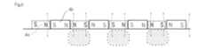
【図6】図6は,移動機構を用いて磁石を移動した後の外部磁石による磁場を示す概念図である。
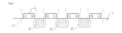
【図7】図7は,隣接する磁石間に磁性材料を含むイオンポンプにおける,外部磁石による磁場を示す概念図である。
【図8】図8は,本発明の真空運搬装置を説明するための概念図である。図8(a)は背面図を示し,図8(b)は側面図を示す。
【図9】図9は,実際に製造した真空運搬装置を示す図面に替わる写真である。
【図10】図10は,試料が搭載された試料基板の例を示す概念図である。図10(a)は,全ての試料据付ステージにそれぞれの試料台が搭載されたものを示し,図10(b)は試料台のひとつが他の試料台に搭載されたものの例を示す。図10(c)は,重ねられた試料台を固定した様子を示す。
【図11】図11は,移動機構の例を示す図である。図11(a)は,移動軸が縮小している状態を示し,図11(b)は移動軸が伸びた状態を示す。
【図12】図12は,マグネットカップリング式の駆動機構の例を示す図である。
【図13】図13は,試料基板を用いて試料を運搬する工程を説明するための概念図である。
【図14】図14は,収容ケースの例を示す,図面に代わる写真である。
【図15】図15は,本発明の真空運搬装置を示す図面に代わる写真である。
【図16】図16は,真空運搬装置を,収容ケース内に収容した例を示す図面に代わる写真である。
【図17】図17は,実施例における真空運搬システムを実際に持ち運ぶ際の例を示す図面に代わる写真である。
【符号の説明】
【0040】
1 ケーシング
2 陽極
3 陰極
4 磁石
5 接続部
6 イオンポンプ
【発明を実施するための最良の形態】
【0041】
以下,本発明を実施するための最良の形態について説明する。本発明の真空運搬システムは,試料を収容するための試料室(11)と,前記試料室内を真空にするためのイオンポンプ(6)と,前記試料室及びイオンポンプを収容する収容ケース(21)と,を備えた持ち運び可能な真空運搬システム(22)である。
【0042】
1 イオンポンプ
図1は,本発明のイオンポンプを説明するための概略図である。図1(a)は,ケーシングが第2の電極を兼ねるものの断面図を示す。図1(b)は,外面から,ケージング(1),円筒状磁石(4),第2の電極(3)が設けられるものの断面図を示す。図1(c)は,ケージングの形状が磁石を収容するための凹凸を有しており,その凹凸内に磁石が設置されるものの断面図を示す。図1に示されるように,本発明の第1の側面に係るイオンポンプは,ケーシング(1)と,第1の電極(2)と,第2の電極(3)と,円筒状磁石(4)と,接続部(5)とを具備するイオンポンプ(6)に関する。第1の電極(2)は,ケーシング(1)の内側に設けられる。第2の電極(3)は,ケーシング(1)の内壁に固定される。また,第2の電極(3)は,第1の電極(2)の外周に設置される。そして,第1の電極と第2の電極とは極性が異なる。すなわち,第1の電極と第2の電極の一方が陽極で残りが陰極である。円筒状磁石(4)は,第2の電極(3)の外周を囲うように設置される。この磁石は,ケーシング(1)の外に設けられても良い。接続部(5)は,ケーシング(1)を他の装置と接続するための機構である。
【0043】
このイオンポンプは,第2の電極をケーシングの内壁に固定する。また,このイオンポンプは,第2の電極を第1の電極の外周に設置する。さらに,円筒状磁石(4)が,第2の電極(3)の外周を囲う。これにより,このイオンポンプは,3次元的な磁場を得ることができ,しかも小型化を達成できる。なお,好ましいイオンポンプは,ケーシングの内壁又はケーシングの側壁が第2の電極を兼ねるものである。なお,本発明のイオンポンプは,持ち運び可能なものであることが好ましい。このため,電源として,電池を用いたイオンポンプが好ましい。このイオンポンプは,電池からの直流電圧を,適宜変換器を用いて更に高圧の直流電圧又は交流電圧に変換して用いればよい。
【0044】
本発明の好ましいイオンポンプは,ケーシング(1)が,円筒状である。そして,第1の電極(2)はケーシングの中心軸上に設けられる棒状電極であるか,又はケーシングと同心円状の円筒状の電極である。そして,第2の電極(3)はケーシングと同心円状の円筒状の電極である。また,円筒状磁石(4)はケーシングと同心円状の円筒状である。このように,同心円状に各要素が設置されるので,効率よくイオン等を発生させ気体を捕捉できる。以下,本発明のイオンポンプを構成する各要素について説明する。
【0045】
ケーシング(1)
ケーシングは,イオンポンプの枠体である。この枠体内に,各種電極などが形成されていればよい。なお,磁石は通常ケーシング内に設けられるが,ケーシング外に設けられても構わない。なお,ケーシングの材質として,アルミニウム,チタン,又はステンレスなど公知のものを用いることができる。これらの中では,表面にチタンが蒸着されたアルミニウムが好ましい。表面にチタンが蒸着されたアルミニウムからなるケーシングは,ケーシング内壁そのものを第2の電極として用いることできる。このようにすることで,イオンポンプを軽くすることができるとともに,構造をシンプルにして,小さくすることもできる。もっとも,第2の電極とケーシングとが,たとえば,同心円状に設けられ,それらの隙間に複数の磁石が設けられるとともに,それら複数の磁石間に第2の電極とケーシングとを接続する第2の電極固定部が設けられてもよい。そのようにすることで,第2の電極を効果的にケーシングと固定することができる。
【0046】
第1の電極(2)
第1の電極に用いられる材質として,公知のものを適宜採用することができる。第1の電極(2)はケーシングの中心軸上に設けられる棒状電極であるか,又はケーシングと同心円状の円筒状の電極であるものが好ましい。第1の電極は,たとえば,陽極であるが,陰極であっても構わない。また,第1の電極の極性を変えることができるような極性制御装置を具備するものは本発明の好ましい態様である。
【0047】
図2は,イオンポンプ内の第1の電極の状況を示す図である。図2に示されるように,好ましいイオンポンプは,第1の電極(2)の一端がケーシング(1)に固定される。図2において,第1の電極の一端は,点線で示される領域においてケージング端面に固定されている。そして,第1の電極(2)のうち,ケーシングに固定される一端と逆側の領域には,スペーサ(8)が設けられる。スペーサを介して第1の電極がケーシングに固定される。第1の電極(2)をケーシングに固定するためのスペーサは,第1の電極のうちケーシングに固定されていない方の部分をケーシング又は第2の電極と固定するためのものである。これにより,第1の電極の先端が振れることを防止することができる。具体的なスペーサは,第1の電極をハブとした場合の車輪のスポークのように第1の電極から複数の線状のスペーサが第2の電極又はケーシングまで伸びるものがあげられる。
【0048】
通常のイオンポンプでは,第2の電極と第1の電極とを絶縁するため,セラミックスなどが用いられる。本発明の好ましいイオンポンプは,第1の電極をケーシングに固定する。これにより,イオンポンプが稼働している際に外部から振動や衝撃が加えられた場合にも,第1の電極が振れて第2の電極と接触する事態を防止できる。そのため,このイオンポンプは,セラミックスなどの絶縁物を用いる必要が無くなり,効率的に真空度を上げることができることとなる。また,このイオンポンプは,スペーサにより,第1の電極がさらに強固に固定されるので,イオンポンプが稼動していても,第1の電極が振れて第2の電極と接触する事態を効果的に防止できる。
【0049】
第2の電極(3)
第1の電極に用いられる材質として,公知のものを適宜採用することができる。第2の電極(3)は,ケーシングと同心円状の円筒状の電極であるものが好ましい。第2の電極は,第1の電極と極性が異なる。すなわち,第1の電極が陽極の場合,第2の電極は陰極である。
【0050】
円筒状磁石(4)
本発明では円筒状磁石(4)として,ケーシングの中心軸方向に空間を空けて並んだ複数の円筒状磁石を用いる。本発明では,リング状の永久磁石を複数並べたものを用いることが好ましい。このリング状の永久磁石は,それぞれ同一の幅を有するものであることが好ましい。また,リング状の永久磁石は,等間隔に配置されることが好ましい。この態様のイオンポンプでは,ひとつの円筒状の磁石を用いるのではなく,複数個の円筒状磁石に分割し,所定のスペースをあけてそれらを設置するので,イオンポンプを軽くすることができるとともに,効率的な磁場を得ることができる。なお,永久磁石の代わりに電磁石を用いても良い。
【0051】
本発明の第1の側面の好ましい態様は,図3に示されるように,複数の円筒状磁石を,ケーシング(1)の長手方向へ向けて移動する移動機構(14)をさらに有する,上記いずれかに記載のイオンポンプに関する。このような移動機構(14)を有することで,磁場の集中する部位を変化させることができるので,システムの劣化を防止できるとともに,システムの効率を上げることができる。なお,移動機構は,磁石の移動を手動で行うものであっても良い。
【0052】
本発明の第1の側面の好ましい態様は,円筒状磁石が,ケーシング(1)から取り外しできるものに関する。このように円筒状磁石を取り除くことができるので,生産性が向上し,メンテナンスが容易になる。
【0053】
図3は,移動機構を有するイオンポンプの概念図である。すなわち,この態様のイオンポンプは,磁場が強かった位置から磁場が弱かった位置へと磁石を移動させるための移動機構を有する。これにより,磁石を移動前の状態(4a)から移動後の状態(4b)へと磁石を移動させることができる。具体的には,複数の円筒状磁石を一体化させるとともに,一体化した複数の円筒状磁石がスライドできるように設置しておく。そして,複数の円筒状磁石にアクチュエータを接続する。アクチュエータは制御部に接続されている。そして,制御部が円筒状磁石を移動させるようアクチュエータに指令を出す。すると,アクチュエータは,円筒状の磁石を所定量動かす。このようにして,円筒状磁石を所定量動かすことができる。
【0054】
図4は,固定された外部磁石を有するイオンポンプにおいて,外部磁石による磁場を示す概念図である。図中,磁場が符号21で示されている。図4に示されるように,外部磁石が固定された場合,磁場がケーシング内部のみならず,ケーシング外部へ漏れ出すことになる。
【0055】
図5は,固定された外部磁石を有するイオンポンプにおいて,外部磁石による磁場の集中する箇所を示す概念図である。図5に示されるように,固定された外部磁石を有するイオンポンプでは,符号22で示される部位に磁場が集中する。すなわち,固定された外部磁石を有するイオンポンプでは,ゲッター面が集中しており,真空効率が早く低下する。また,ゲッター面が集中するため,このイオンポンプは,早く劣化するおそれがある。
【0056】
図6は,移動機構を用いて磁石を移動した後の外部磁石による磁場を示す概念図である。図6に示されるように,移動機構を用いることで,磁場の集中する位置をずらすことができる。これにより,分子が付着していない面に分子を吸着することができ,吸着効率を上げることができる。移動機構の例は,先に説明したとおり,複数の円筒状磁石間を接続しておき,アクチュエータを用いて永久磁石に力を加え,複数の円筒状磁石の位置を変化させるものである。
【0057】
本発明の第1の側面の好ましい態様は,複数の円筒状磁石は,隣接する円筒状磁石の面が同じ極性を有する面となるように構成される。そして,この態様のイオンポンプは,複数の円筒状磁石のうち隣接する磁石の間に,さらに磁性材料を含む。その磁性材料は,隣接する面から前記ケーシング(1)の中心軸方向へ向かう磁場が強くなるように配置される。このように隣接する磁石の間に磁性材料が置かれるので,磁束の空間分布を整え,電極方向への磁束進入を促進することができる。このような磁性材料として,永久磁石,電磁石,軟鉄,鉄,フェライトなど,磁束整流効果を有するものがあげられる。
[0058]
図7は,隣接する磁石間に磁性材料を含むイオンポンプにおける,外部磁石による磁場を示す概念図である。図7は,磁性材料として磁石を用いたものの例である。図7に示されるように,このイオンポンプは,外部円筒状磁石(4)の間にさらに磁石を配置することで,ケーシング内に形成される磁場をより強化することができる。これにより,システムの効率を上げることができる。このような磁石間の磁石は,円筒状の磁石であってもよい。
[0059]
たとえば,隣接する円筒状磁石(4)がN極を向け合って配置されているとする。この場合,円筒状磁石の間には,N極の磁場が形成される。この隣接した円筒状磁石の間であって,それらの磁石の上方に,新たな磁石を設置する。この円筒状磁石の間の磁石(24)は,下方向がN極を向くように設置される。このようにすることで,隣接する円筒状磁石(4)が形成するN極の磁場を強化することができる。この円筒状磁石の間の磁石も,円筒状又はリング状であることが好ましい。このリング状の磁石は,隣接する円筒状磁石の間に設けられ,かつ,円筒状磁石よりも直径が大きなものが好ましい。
[0060]
接続部(5)
接続部(5)は,ケーシングを他の装置と接続するための部位である。「他の装置」として,真空チャンバや試料室などの真空状態にする対象があげられる。具体的な接続部(5)として,フランジがあげられる。
[0061]
イオンポンプ(6)
イオンポンプの動作原理は公知である。イオンポンプの動作原理を,以下簡単に説明する。イオンポンプの第2の電極−第1の電極間に数kV程度の電圧を印加すると,第2の電極から一次電子が放出される。第2の電極から放射された一次電子は,第1の電極に引きつけられつつ,永久磁石から与えられる磁場の影響を受けるため,旋回して長い螺旋運動を描き,第1の電極に至る。この途中で,一時電子は中性のガス分子と電離衝突を起こして,多数の正イオンと二次電子を生成する。生成した二次電子は更に螺旋運動を行って,他のガス分子と衝突して正イオンと電子を生成する。そして,各イオンなどは電極に吸着される。
【0062】
本発明の第1の側面に係るイオンポンプは,上記の構成のほか,イオンポンプに用いられる公知の構成を適宜採用することができる。たとえば,適宜,加熱装置や冷却装置などが取り付けられていてもよい。冷却装置により冷却を行うことで,ガスの補修効率を向上させることができる。一方,加熱装置で各電極を加熱することで,真空状態を維持することにより電極に捕捉されたガスを放出することができる。
【0063】
2 真空運搬装置
図8は,本発明の真空運搬装置を説明するための概念図である。図8(a)は背面図を示し,図8(b)は側面図を示す。図8に示されるように,本発明の第2の側面に係る真空運搬装置(33)は,試料室(31)と,イオンポンプ(6)とを含む。試料室(31)は,試料を出し入れするとともに,他の装置と接続可能なゲート部(34)と,イオンポンプと接続するための接続部(35)を含む。そして,イオンポンプ(6)として,先に説明したイオンポンプを適宜利用することができる。なお,図中符号36は電源(電池)を示し,符号37はビューポートを示す。
【0064】
この真空運搬装置を用いれば,試料室に収容した試料を真空環境におきつつ運搬できることとなる。すなわち,「持ち運び可能な真空運搬装置」とは,イオンポンプを稼動させた状態のまま,移動させることができる運搬装置を意味する。なお,真空運搬装置におけるイオンポンプとして,先に説明したイオンポンプ及びこれらから自明なイオンポンプを適宜用いることができる。このような効率的で小型なイオンポンプを用いることで,本発明の真空運搬装置は,軽量化できる。
【0065】
試料室(31)には,たとえば試料台が設けられ,試料が固定されている。また,試料は,移動できるようにされていても良い。そして,その試料のおかれる雰囲気が,イオンポンプにより真空状態に維持される。試料室は,真空チャンバなどがあげられる。ゲート部(34)の例としては,ゲートバルブがあげられる。これにより,真空状態を維持することや,試料室を開閉することができ,また試料室内の真空状態を維持したまま他の真空装置と接続することができる。接続部(35)は,試料室内の真空状態を維持しつつイオンポンプと接続できるものであれば特に限定されない。電源(36)として,公知の電池を適宜用いることができる。ビューポート(37)は,任意のものである。ビューポートによりチャンバ内の様子を見ることができる。また,ビューポート(37)を用いて観察実験を行うことができる。さらに,フィードスルー(電流導入端子)を設置することで,抵抗測定を行うことができ,またサンプルを加熱できる。
【0066】
なお,特に図示しないが,リング状の磁石の間に管口を設け,その管口と他の真空チャンバなどの真空にする対象系とを接続し,それら複数の対象系を真空状態に維持するものであってもよい。このような構成を採用することで,複数の対象を容易に真空に維持できることとなる。特に,超高真空に維持する必要のない複数の対象系を運搬する際に,効果的にこのようなシステムを用いることができることとなる。
【0067】
図9は,試料基板の例を示す概念図である。図9に示されるように,好ましい試料基板(41)は,試料据付ステージ(42)を,試料室(11)の長手方向に一列に複数有する。試料据付ステージ(42a,42b,42c)は,試料台を搭載するためのものである。図9に示されるように,たとえば,試料据付ステージ(42)は,試料台の形状に合わせた窪みによって形成することができる。すると,試料据付ステージ(42)に対応する試料台が,試料据付ステージ(42)上に置かれると,その窪みにはまる。このようにして,試料台が固定される。これにより,試料を運搬する際に,試料台が移動する事態を効果的に防止できる。
[0068]
このように複数種類の試料台を搭載するための試料据付ステージ(42)を具備する試料基板(41)を有するので,真空チャンバによって試料台が異なっていても,運搬した試料を新しい真空チャンバ内で用いることができる。
[0069]
図10は,試料が搭載された試料基板の例を示す概念図である。図10(a)は,全ての試料据付ステージにそれぞれの試料台が搭載されたものを示し,図10(b)は試料台のひとつが他の試料台に搭載されたものの例を示す。図10(c)は,重ねられた試料台を固定した様子を示す。図10に示されるように,本発明の好ましい態様は,試料基板(41)が,試料据付ステージ(42)を,試料室(11)の長手方向に一列に複数有する。
[0070]
このように複数種類の試料台(43)を搭載するための試料据付ステージ(42)を具備する試料基板(41)を有するので,真空チャンバによって試料台が異なっていても,運搬した試料を新しい真空チャンバ内で用いることができることとなる。
[0071]
本発明の好ましい態様は,試料室が,試料台配置移送部と,固定機構とを含むものである。試料台配置移送部は,複数種類の試料台(43)を重ねて配置するための機構を含む。そして,固定機構は,試料台配置移送部により重ねて配置された複数の試料台(43)を固定するための機構を含む。たとえば,試料室は,その天井部分にレールが設けられている。そして,試料台配置移送部は,レールに沿って移動できる。試料台配置移送部は,昇降機構(44)を含む。昇降機構は,たとえば,2本の伸縮できるアームを含む。そして,2本のアームの先端には,横方向に移動できる把持部(45)が設けられている。または,2本のアームの先端には,下方に移動できる把持部(45)が設けられている。そして,昇降機構は,把持部を天井から試料台へ移動できる。また,昇降機構は,把持部を試料台の位置から天井付近へ移動できる。
[0072]
ある試料台Aを他の試料台Bに搭載する場合は,たとえば,以下のようにすればよい。まず,試料台配置移送部が,試料台Aの上部に移動する。そして,試料台配置移送部の昇降機構が,試料台Aへ向けて下へ移動する。昇降機構の2本のアームが試料台Aの側面まで移動する。その後,2本のアームのそれぞれから,試料台Aへ向けて把持部が出される。2つの把持部は,試料台Aを把持する。昇降機構は,試料台Aを把持した状態で,上方へ移動する。試料台配置移送部は,試料台Aを把持したまま,レールに沿って移動する。試料台配置移送部が,試料台Bの上方へ移動する。その後,試料台配置移送部は,昇降機構を試料台Bへ向けて下のほうへ移動させる。昇降機構は,試料台Bの上方へ試料台Aを搭載する。昇降機構は,把持部を試料台Aから外す。そして,昇降機構は,天井付近へ移動する。
【0073】
図10(c)は,重ねられた試料台を固定した様子を示す。すなわち,本発明の好ましい態様は,重ねられた試料台を固定するものである。具体的には,昇降機構(44)が,試料台Bの上方へ試料台Aを搭載した後に,把持部(45)が試料台A又は試料台Bを押さえればよい。たとえば,一端天井付近へ移動した昇降機構が,2本のアームの間隔を試料台Aの幅より広く,試料台Bの幅より狭く調整する。この状態で,昇降機構が,試料台Bへ向けて下方へ移動する。そして,試料台Bの付近まで昇降機構が下がる。この後,昇降機構から把持部(45)が下の方へ出される。この把持部は,試料台Bを上方から押し付ける。このようにして,試料台Bを固定できる。なお,アームの間隔を試料台Aより狭くすることで,試料台Aを上から押し付けることもできる。さらに,昇降機構自体が,試料台A又は試料台Bを押し付けるようにしてもよい。このようにして,重ねられた試料台を固定できる。なお,この固定機構は,重ねられた試料台だけではなく,各試料台を固定するために用いられても良い。
【0074】
このように,試料台を重ねて設置できるので,様々な種類の真空チャンバに試料を運搬できる。
【0075】
図11は,移動機構の例を示す図である。すなわち,本発明の好ましい態様は,試料室(11)が,試料基板(41)を駆動する駆動機構(51)を含む。駆動機構は,真空系において,試料基板を移動できるものであれば,特に限定されない。そして,この駆動機構は,試料基板(41)を試料室(11)の内部から外部へ移動することができる。さらに,この駆動機構は,試料基板(41)を試料室(11)の外部から内部へ移動することもできる。
【0076】
図11に示される駆動機構(51)は,伸縮できる移動軸(52)が,試料基板(41)に取り付けられている。図11(a)は,移動軸が縮小している状態を示し,図11(b)は移動軸が伸びた状態を示す。駆動機構として,この移動軸(52)自体が,何らかのアクチュエータにより駆動されてもよい。この場合,アクチュエータに伸縮するよう指令を送ることで,試料基板を移動できる。また,図11に示されるように,移動軸(52)を中心として,折れ曲がった足(53,54)が設けられたものであっても良い。この足(53,54)を伸ばすことで,移動軸(52)を伸ばすことができる。これにより,試料基板(41)を移動することができる。なお,上記とは別の駆動機構(51)として,マグネットカップリング式の駆動機構が好ましい。マグネットカップリング式の駆動機構として,公知のものを適宜採用できる。
【0077】
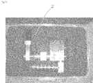
図12は,マグネットカップリング式の駆動機構の例を示す図である。この駆動機構(51)は,ロッド(61),チューブ(62),内部移動体(63),及び外部移動体(64)を含む。そして,ロッド(61)は,試料基板(41)へ動力を伝えることができるように,試料基板(41)と接続されている。なお,ロッド(61)は,試料基板と直接接続されても良い。また,ロッド(61)は,軸を介して試料基板と接続されても良い。図12に示されるように,内部移動体(63)は,マグネット(65)とヨーク(66)とを交互に積層した本体部(67)を有する。内部移動体の外径は,チューブの内径よりわずかに小さい。一方,外部移動体(64)は,マグネット(68)とヨーク(69)とを交互に積層した本体部(70)を有する。外部移動体の内径は,チューブの外径よりわずかに大きい。外部移動体は,アクチュエータ(71)と接続されている。そして,アクチュエータ(71)が駆動信号を受けると,外部移動体(64)は,チューブの外周面にそって移動する。すると,内部移動体(63)も移動する。内部移動体(63)が移動すると,ロッドが移動する。ロッドが移動すると,試料基板が移動する。このようにアクチュエータ(71)を駆動することで,試料基板を移動させることができる。
【0078】
図13は,試料基板を用いて試料を運搬する工程を説明するための概念図である。図13では,真空チャンバAで加工された試料を,別の真空チャンバBへと輸送する例を示す。そして,真空チャンバAに用いられる試料台(43b)と,真空チャンバBに用いられる試料台(43a)とは異なっている。
【0079】
まず,試料室(11)のゲートバルブが開かれており,真空チャンバAと試料室(11)とは,同一の雰囲気に置かれている。もっとも,ゲートバルブが閉じられていて,真空チャンバAと試料室(11)とは,別の真空系とされてもよい。
【0080】
真空チャンバA内の試料台(43b)上で試料に所定の加工が施される。その試料は,試料台(43b)とともに真空チャンバA内で試料基板(41)の試料据付ステージ(42)へと移送される。この際の試料据付ステージ(42)は,試料台(43b)にフィットしたものであり,他の場所へ真空運搬システムを輸送する間中,試料台は固定されている。次に,試料は,試料台(43b)とともに,別の試料台(43a)上へ搭載される。
【0081】
試料室(11)のゲートバルブが閉じられている場合は,ゲートバルブを開ける。そして,試料基板(41)を,試料室(11)へと移動する。その後,試料室(11)のゲートバルブを閉じる。その後,真空チャンバAと試料室(11)とを分離する。分離された試料室(11)はイオンポンプで真空を保ちつつ,収容ケースに収容され,チャンバBが存在する別の箇所へと輸送される。
【0082】
チャンバB内を超高真空状態としたのち,試料室(11)と真空チャンバBとを接続する。その後,試料室(11)のゲートバルブを開く。これにより,試料室(11)と真空チャンバBとを開通させる。そして,試料基板(41)を真空チャンバB内へ移送する。その後,試料基板(41)から,試料台(43a)を移送して,試料台(43a)上の試料に適宜加工を施す。
【0083】
3 収容ケース
図14は,収容ケースの例を示す,図面に代わる写真である。図14に示されるように,収容ケース(21)は,収容ケースの枠体(23)と,前記枠体内部に設けられ,前記試料室及び前記イオンポンプの形状に相当する空隙が設けられ,前記空隙に前記試料室及び前記イオンポンプを設置できる収容部(24)と,を具備する。
【0084】
収容ケースの枠体(23)
収容ケースの枠体(23)として,公知の枠体を適宜採用できる。本発明の真空運搬システムは,空輸などにより長距離の輸送を行うことが好ましいため,枠体として,アルミニウム,ジュラルミンなどのものがあげられる。枠体の大きさは,航空機に手荷物として持ち運ぶことができる程度の大きさが好ましい。
【0085】
収容部
収容部は,前記試料室及び前記イオンポンプの形状に相当する空隙が設けられ,前記空隙に前記試料室及び前記イオンポンプを設置できるものであれば特に限定されない。
【実施例1】
【0086】
本発明のイオンポンプおよび真空運搬装置のプロトタイプを製造した。図15は,本発明の真空運搬装置を示す図面に代わる写真である。
【0087】
このイオンポンプでは,陰極を兼ねるケーシングの外周にリング状の永久磁石が5個等間隔で設置されている。この真空運搬装置では,酸化アルミニウム膜を有するアルミニウムで枠体を形成した。また,別の真空運搬装置として,酸化チタン膜を有するチタンで枠体を形成した。ゲートバルブとして,1.42”ルーティングポートを有する2.75”ゲートバルブを用いた。サンプルロックとして,ベローを有するアップダウンクランプを用いた。電源は電池を用いた。また,試料室内の真空度を測定するための真空計を設置した。
【0088】
この真空運搬装置は,試料として,最大直径35mmのものを設置できた。また,内部圧力は1×10⁻⁶Pa以下の高真空を達成できた。連続して真空を維持しても15時間の連続稼動を維持できた。全重量は10kg程度であった。
【0089】
図16は,真空運搬装置を,収容ケース内に収容した例を示す図面に代わる写真である。図16に示されるように,収容ケースには前記試料室及び前記イオンポンプの形状に相当する空隙が設けられるので,前記試料室及び前記イオンポンプを収容することができ,しかも輸送中の揺れを少なくすることができる。なお,収容部に衝撃吸収ゲル層を設け,空隙部を取り囲むなど,揺れを防止する手段を適宜用いてもよい。
【0090】
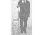
図17は,実施例における真空運搬システムを実際に持ち運ぶ際の例を示す図面に代わる写真である。図17に示されるとおり,手荷物として運搬できる程度の重量と大きさを有する真空運搬システムを得ることができた。
【産業上の利用可能性】
【0091】
本発明のイオンポンプおよび真空運搬装置は,小型でかつ軽量なので,真空装置産業において好適に利用されうる。
【0092】
本発明の真空運搬システムは,実験サンプルや試料などを真空状態を維持したまま運搬できるので,運送業においても好適に利用できる。【Technical field】
[0001]
The present invention relates to a vacuum carrying system using an ion pump apparatus that is miniaturized so as to be portable by introducing a three-dimensional magnetic field.
[Background]
[0002]
As nanotechnology and ultra-precision measurement technology develop, ultra-high vacuum technology is gaining importance. The semiconductor surface is easily contaminated by gas molecules. On the other hand, a clean semiconductor surface can be maintained by maintaining the semiconductor in an ultrahigh vacuum of about 10−7 Pa or less. A pump such as an ion pump is used to maintain an ultra-high vacuum.
[0003]
In the conventional ion pump, for example, as shown in FIGS. 4A and 4B of JP-A-9-27294, flat permanent magnets face each other in parallel with a rectangular parallelepiped container. Was arranged to be. For this reason, the magnetic field is unidirectional, and the space in the ion pump cannot be used effectively.
[0004]
In order to solve such problems, claim 1 of Japanese Patent Laid-Open No. 9-27294 (
[0005]
Further,
[0006]
However, since such an ion pump insulates between electrodes, it was necessary to use many insulators, such as ceramics. For this reason, gas was generated from ceramics and the like, and there was a problem that the degree of vacuum was lowered. In addition, such an ion pump has a problem that its strength is not sufficient.
[0007]
In addition, since such an ion pump is large and heavy and also consumes a large amount of power, there is a problem that it cannot be easily moved once installed. Therefore, a vacuum carrying system that can carry the sample while operating the ion pump and maintaining the atmosphere in which the sample is placed in a vacuum is desired.
[0008]
In general, the vacuum device is a built-in type and is made to order. Some have a sample stage for mounting a sample in a vacuum chamber. The sample stage varies from manufacturer to manufacturer. Therefore, even if a vacuum carrying system is developed, there may be a problem that the carried sample cannot be transferred to the sample tables of various vacuum chambers.
[Patent Document 1]
JP-A-9-27294 [Patent Document 2]
JP 2001-332209 A DISCLOSURE OF THE INVENTION
[Problems to be solved by the invention]
[0009]
An object of the present invention is to provide a portable vacuum carrying system.
[0010]
An object of this invention is to provide the portable vacuum conveyance system which can deliver a sample in various vacuum chambers.
[Means for Solving the Problems]
[0011]
In the present invention, basically, a three-dimensional magnetic field can be obtained by using a casing of an ion pump as a cathode and continuously installing a plurality of ring-shaped permanent magnets on the outer periphery of the ion pump casing. It is based on the knowledge that can be achieved. In addition, the use of such an ion pump is based on the knowledge that a transportable vacuum transport system capable of maintaining the sample chamber in a vacuum can be obtained.
[0012]
The first aspect of the present invention relates to a vacuum carrying system (22). This system includes a sample chamber (11) for containing a sample, and an ion pump (6) for evacuating the sample chamber (11). The sample chamber (11) includes a gate portion (14) for connecting to another device and a connection portion (15) for connecting to the ion pump (6). The ion pump (6) includes a casing (1), a first electrode (2), a second electrode (3), a magnet (4), and a connection portion (5). The first electrode is provided inside the casing (1). The second electrode (3) is fixed to the inner wall of the casing (1) and installed on the outer periphery of the first electrode (2). The second electrode (3) is different in polarity from the first electrode (2). The magnet (4) is installed so as to surround the outer periphery of the second electrode (3). The connection part (5) includes a mechanism for connecting the casing (1) to another device.
[0013]
If this vacuum carrying system is used, the sample case and the ion pump can be carried while being accommodated in the accommodating case, so that the sample accommodated in the sample chamber can be easily conveyed while being placed in a vacuum environment.
[0014]
A preferred embodiment of the first aspect of the present invention further includes a storage case (21). This accommodation case accommodates the sample chamber (11) and the ion pump (6). The storage case (21) includes a frame (23) of the storage case and a storage portion (24). The accommodating portion (24) is provided inside the frame (23). The accommodating portion (24) includes a gap corresponding to the shape of the sample chamber and the ion pump. A sample chamber and an ion pump can be installed in this gap.
[0015]
The vacuum carrying system of the present invention is connected to an ion pump. Therefore, under normal circumstances, I do not think that I will transport the vacuum transport system in an attache case. However, the vacuum carrying system of the present invention can be miniaturized. Therefore, the system of this aspect can be transported by putting the sample chamber and the ion pump in the storage case (21). As a result, the sample chamber can be easily transported while maintaining a vacuum.
[0016]
In a preferred embodiment of the first aspect of the present invention, the ion pump includes a casing (1), a first electrode (2), a second electrode (3), a plurality of cylindrical magnets (4), And a connecting portion (5). The first electrode (2) is provided inside the casing (1). The second electrode (3) is fixed to the inner wall of the casing (1). The second electrode (3) is disposed on the outer periphery of the first electrode (2). The first electrode and the second electrode have different polarities. The cylindrical magnet (4) is installed so as to surround the outer periphery of the second electrode (3). This magnet may be provided outside the casing (1). The connection part (5) is a mechanism for connecting the casing (1) to another device. The plurality of cylindrical magnets (4) are installed so as to surround the outer periphery of the second electrode (3). The plurality of cylindrical magnets (4) are arranged side by side with a space in the central axis direction of the casing (1).
[0017]
In this ion pump, the second electrode (for example, cathode) is fixed to the inner wall of the casing, and the second electrode is installed on the outer periphery of the first electrode (for example, anode). And this ion pump installs a some cylindrical magnet (4) so that the outer periphery of a 2nd electrode (3) may be enclosed. Thereby, a three-dimensional magnetic field can be obtained, and further downsizing can be achieved. In the preferred example of the ion pump, the inner wall of the casing or the side wall of the casing also serves as the second electrode. In this way, further downsizing can be achieved. In addition, since it is preferable that the ion pump of this invention is portable, what uses a battery as a power supply is preferable. The DC voltage from the battery may be converted into a higher voltage DC voltage or AC voltage using a converter as appropriate.
[0018]
In the present invention, the cylindrical magnet (4) is preferably a plurality of cylindrical magnets arranged with a space in the direction of the central axis of the casing.
[0019]
Magnets are generally heavy. In the ion pump of this aspect, instead of using a single cylindrical magnet, it is divided into a plurality of cylindrical magnets, and they are installed with a predetermined space. As a result, the ion pump can be lightened and an efficient magnetic field can be obtained. Furthermore, the difficulty in processing for the shape and size of the pump casing is greatly improved by using a plurality of small magnets that are easy to shape instead of large magnets that require time for shape processing.
[0020]
A preferred embodiment of the first aspect of the present invention has a magnet moving mechanism. The moving mechanism (14) moves the plurality of cylindrical magnets in the longitudinal direction of the casing (1). By having such a moving mechanism (14), the part where the magnetic field concentrates can be changed. As a result, system degradation can be prevented and system efficiency can be increased. This configuration can be employed in any of the ion pumps described above. The moving mechanism may be one that manually moves the magnet.
[0021]
A preferred embodiment of the first aspect of the present invention relates to a cylindrical magnet that can be removed from the casing (1). Since the cylindrical magnet can be removed in this way, productivity is improved and maintenance is facilitated.
[0022]
In a preferred embodiment of the first aspect of the present invention, the plurality of cylindrical magnets are configured such that the surfaces of the adjacent cylindrical magnets have the same polarity. This includes the case where a magnetic material is further inserted between adjacent magnets. This magnetic material is arranged so that the magnetic field from the adjacent surface toward the central axis of the casing (1) becomes stronger. As described above, since the magnetic material is placed between the adjacent magnets, the spatial distribution of the magnetic flux can be adjusted and the magnetic flux in the direction of the electrode can be promoted. Examples of such a magnetic material include permanent magnets, electromagnets, soft iron, iron, and ferrites that have a magnetic flux rectifying effect. This configuration can be employed in any of the ion pumps described above.
[0023]
Thus, by further disposing the magnetic material between the magnets, the magnetic field formed in the casing can be further strengthened. This can increase the efficiency of the system.
[0024]
In a preferred embodiment of the first aspect of the present invention, the casing (1) is the second electrode (3). That is, the preferred ion pump used in the present invention uses the casing itself as the second electrode (3). Specifically, the casing is made of aluminum with titanium deposited on the surface. This casing functions as the second electrode (3). This configuration can be employed in any of the ion pumps described above. By doing so, the ion pump can be lightened, and the structure can be simplified and made smaller.
[0025]
In a preferred embodiment of the first aspect of the present invention, each element constituting the ion pump is a rod or cylinder. That is, the casing (1) is cylindrical. The first electrode (2) is a rod-shaped electrode provided on the central axis of the casing, or a cylindrical electrode concentric with the casing. The second electrode (3) is a cylindrical electrode concentric with the casing. The cylindrical magnet (4) has a cylindrical shape concentric with the casing. This configuration can be employed in any of the ion pumps described above.
[0026]
Thus, since each element is installed concentrically, ions can be generated efficiently and gas can be captured.
[0027]
The preferable aspect of the 1st side surface of this invention is related with what uses the ion pump by which the end of the 1st electrode (2) was fixed to the casing. This configuration can be employed in any of the ion pumps described above.
[0028]
In an ordinary ion pump or the like, ceramics or the like is often used to insulate the second electrode from the first electrode. In the ion pump of this aspect, since the first electrode is fixed to the casing, it is possible to effectively prevent a situation in which the first electrode swings and contacts the second electrode even when the ion pump is operating. . Therefore, it is not necessary to use many insulators such as ceramics, and the degree of vacuum can be increased efficiently.
[0029]
In a preferred embodiment of the first aspect of the present invention, one end of the first electrode (2) is fixed to the casing. A spacer (8) is provided in a region opposite to the one end fixed to the casing. The spacer fixes the first electrode (2) to the casing. This configuration can be employed in any of the ion pumps described above.
[0030]
In an ordinary ion pump or the like, ceramics or the like is often used as an insulator to insulate the second electrode from the first electrode. In the ion pump of this aspect, since the first electrode is fixed to the casing, it is possible to effectively prevent a situation in which the first electrode swings and contacts the second electrode even when the ion pump is operating. . Therefore, it is not necessary to use many insulators such as ceramics, and the degree of vacuum can be increased efficiently. In addition, since the first electrode is more firmly fixed by the spacer, it is possible to more effectively prevent a situation in which the first electrode swings and contacts the second electrode even when the ion pump is operating.
[0031]
In a preferred embodiment of the first aspect of the present invention, the sample chamber (11) includes a sample substrate (41) for mounting a sample, and the sample substrate (41) includes a plurality of types of sample stands (43). The vacuum carrying system (22) according to any one of the above, which has a plurality of sample installation stages (42) for mounting a sample chamber in a longitudinal direction of the sample chamber (11).
[0032]
Since the sample substrate (41) having the sample mounting stage (42) for mounting a plurality of types of sample stands (43) is thus provided, the transported sample can be renewed even if the sample stage differs depending on the vacuum chamber. It can be used in a vacuum chamber.
[0033]
In a preferred embodiment of the first aspect of the present invention, the sample substrate (41) includes a sample table arrangement transfer unit for arranging the plurality of types of sample tables (43) in an overlapping manner, and the sample table arrangement transfer unit. A vacuum carrying system (22) according to any one of the above, comprising a fixing mechanism for fixing a plurality of sample stands (43) arranged in an overlapping manner.
[0034]
In this way, since the sample stage can be installed in piles, the sample can be transported to various types of vacuum chambers.
[0035]
In a preferred embodiment of the first aspect of the present invention, the sample chamber (11) includes a drive mechanism (51) for driving the sample substrate (41). And this drive mechanism can move the sample substrate (41) from the inside of the sample chamber (11) to the outside. Furthermore, this drive mechanism can also move the sample substrate (41) from the outside to the inside of the sample chamber (11). As this drive mechanism (51), a magnet coupling type drive mechanism is preferable.
[0036]
As described above, the system having the drive mechanism can easily move the sample substrate from the inside of the sample chamber to the outside, and can easily move the sample substrate from the outside to the inside of the sample chamber.
【The invention's effect】
[0037]
According to the present invention, a portable vacuum carrying system can be provided.
[0038]
ADVANTAGE OF THE INVENTION According to this invention, the portable vacuum conveyance system which can deliver a sample in various vacuum chambers can be provided.
[Brief description of the drawings]
[0039]
FIG. 1 is a schematic view for explaining an ion pump used in the present invention. Fig.1 (a) shows sectional drawing of what a casing serves as a 2nd electrode. FIG.1 (b) shows sectional drawing of what is provided with a caging (1), a cylindrical magnet (4), and a 2nd electrode (3) from an outer surface. FIG.1 (c) shows sectional drawing of the thing where the shape of caging has the unevenness | corrugation for accommodating a magnet, and a magnet is installed in the unevenness | corrugation.
FIG. 2 is a diagram illustrating a state of a first electrode in an ion pump.
FIG. 3 is a conceptual diagram of an ion pump having a moving mechanism.
FIG. 4 is a conceptual diagram showing a magnetic field generated by an external magnet in an ion pump having a fixed external magnet.
FIG. 5 is a conceptual diagram showing a location where a magnetic field is concentrated by an external magnet in an ion pump having a fixed external magnet.
FIG. 6 is a conceptual diagram showing a magnetic field generated by an external magnet after the magnet has been moved using a moving mechanism.
FIG. 7 is a conceptual diagram showing a magnetic field generated by an external magnet in an ion pump including a magnetic material between adjacent magnets.
FIG. 8 is a conceptual diagram for explaining a vacuum carrying device of the present invention. FIG. 8A shows a rear view, and FIG. 8B shows a side view.
FIG. 9 is a photograph replacing a drawing showing the actually manufactured vacuum carrying device.
FIG. 10 is a conceptual diagram illustrating an example of a sample substrate on which a sample is mounted. FIG. 10A shows an example in which each sample stage is mounted on all sample mounting stages, and FIG. 10B shows an example in which one of the sample stages is mounted on another sample stage. FIG. 10C shows a state in which the stacked sample stands are fixed.
FIG. 11 is a diagram illustrating an example of a moving mechanism. FIG. 11A shows a state where the movement axis is contracted, and FIG. 11B shows a state where the movement axis is extended.
FIG. 12 is a diagram illustrating an example of a magnet coupling type drive mechanism;
FIG. 13 is a conceptual diagram for explaining a process of transporting a sample using a sample substrate.
FIG. 14 is a photograph replacing a drawing showing an example of a storage case.
FIG. 15 is a photograph instead of a drawing showing the vacuum carrying device of the present invention.
FIG. 16 is a photograph instead of a drawing showing an example in which the vacuum carrying device is housed in a housing case.
FIG. 17 is a photograph replacing a drawing showing an example of actually carrying the vacuum carrying system in the embodiment.
[Explanation of symbols]
[0040]
DESCRIPTION OF
[0041]
Hereinafter, the best mode for carrying out the present invention will be described. The vacuum carrying system of the present invention includes a sample chamber (11) for storing a sample, an ion pump (6) for evacuating the sample chamber, and a storage case (21 for storing the sample chamber and the ion pump). And a portable vacuum carrying system (22).
[0042]
1 Ion Pump FIG. 1 is a schematic view for explaining an ion pump of the present invention. Fig.1 (a) shows sectional drawing of what a casing serves as a 2nd electrode. FIG.1 (b) shows sectional drawing of what is provided with a caging (1), a cylindrical magnet (4), and a 2nd electrode (3) from an outer surface. FIG.1 (c) shows sectional drawing of the thing where the shape of caging has the unevenness | corrugation for accommodating a magnet, and a magnet is installed in the unevenness | corrugation. As shown in FIG. 1, the ion pump according to the first aspect of the present invention includes a casing (1), a first electrode (2), a second electrode (3), and a cylindrical magnet (4 ) And a connection part (5). The first electrode (2) is provided inside the casing (1). The second electrode (3) is fixed to the inner wall of the casing (1). The second electrode (3) is disposed on the outer periphery of the first electrode (2). The first electrode and the second electrode have different polarities. That is, one of the first electrode and the second electrode is an anode and the remaining is a cathode. The cylindrical magnet (4) is installed so as to surround the outer periphery of the second electrode (3). This magnet may be provided outside the casing (1). The connection part (5) is a mechanism for connecting the casing (1) to another device.
[0043]
This ion pump fixes the second electrode to the inner wall of the casing. Moreover, this ion pump installs the second electrode on the outer periphery of the first electrode. Furthermore, a cylindrical magnet (4) surrounds the outer periphery of the second electrode (3). As a result, the ion pump can obtain a three-dimensional magnetic field and can be downsized. In a preferred ion pump, the inner wall of the casing or the side wall of the casing also serves as the second electrode. Note that the ion pump of the present invention is preferably portable. For this reason, an ion pump using a battery is preferable as a power source. This ion pump may be used by converting the DC voltage from the battery into a higher DC voltage or AC voltage using a converter as appropriate.
[0044]
In a preferred ion pump of the present invention, the casing (1) is cylindrical. The first electrode (2) is a rod-shaped electrode provided on the central axis of the casing, or a cylindrical electrode concentric with the casing. The second electrode (3) is a cylindrical electrode concentric with the casing. The cylindrical magnet (4) has a cylindrical shape concentric with the casing. Thus, since each element is installed concentrically, ions can be generated efficiently and gas can be captured. Hereafter, each element which comprises the ion pump of this invention is demonstrated.
[0045]
Casing (1)
The casing is a frame of the ion pump. Various electrodes and the like may be formed in the frame. The magnet is usually provided inside the casing, but may be provided outside the casing. A known material such as aluminum, titanium, or stainless steel can be used as the casing material. Among these, aluminum with titanium deposited on the surface is preferable. In the casing made of aluminum with titanium deposited on the surface, the inner wall of the casing itself can be used as the second electrode. By doing so, the ion pump can be lightened, and the structure can be simplified and made smaller. Of course, the second electrode and the casing are provided concentrically, for example, and a plurality of magnets are provided in the gap between them, and the second electrode and the casing are connected between the plurality of magnets. An electrode fixing part may be provided. By doing so, the second electrode can be effectively fixed to the casing.
[0046]
First electrode (2)
As a material used for the first electrode, a known material can be appropriately adopted. The first electrode (2) is preferably a rod-shaped electrode provided on the central axis of the casing or a cylindrical electrode concentric with the casing. The first electrode is, for example, an anode, but may be a cathode. Moreover, what comprises the polarity control apparatus which can change the polarity of a 1st electrode is a preferable aspect of this invention.
[0047]
FIG. 2 is a diagram illustrating a state of the first electrode in the ion pump. As shown in FIG. 2, in the preferred ion pump, one end of the first electrode (2) is fixed to the casing (1). In FIG. 2, one end of the first electrode is fixed to the caging end face in a region indicated by a dotted line. And a spacer (8) is provided in the area | region on the opposite side to the end fixed to a casing among 1st electrodes (2). The first electrode is fixed to the casing via the spacer. The spacer for fixing the first electrode (2) to the casing is for fixing a portion of the first electrode that is not fixed to the casing to the casing or the second electrode. Thereby, it is possible to prevent the tip of the first electrode from swinging. Specific examples of the spacer include one in which a plurality of linear spacers extend from the first electrode to the second electrode or the casing, such as a wheel spoke in the case where the first electrode is a hub.
[0048]
In a normal ion pump, ceramics or the like is used to insulate the second electrode from the first electrode. In a preferred ion pump of the present invention, the first electrode is fixed to the casing. Accordingly, even when vibration or impact is applied from the outside while the ion pump is operating, it is possible to prevent the first electrode from swinging and coming into contact with the second electrode. Therefore, this ion pump does not require the use of an insulator such as ceramics, and can effectively increase the degree of vacuum. In addition, since the first electrode is more firmly fixed by the spacer in the ion pump, it is effective that the first electrode swings and contacts the second electrode even when the ion pump is in operation. Can be prevented.
[0049]
Second electrode (3)
As a material used for the first electrode, a known material can be appropriately adopted. The second electrode (3) is preferably a cylindrical electrode concentric with the casing. The second electrode has a different polarity from the first electrode. That is, when the first electrode is an anode, the second electrode is a cathode.
[0050]
Cylindrical magnet (4)
In the present invention, as the cylindrical magnet (4), a plurality of cylindrical magnets arranged with a space in the direction of the central axis of the casing are used. In the present invention, it is preferable to use a plurality of ring-shaped permanent magnets. The ring-shaped permanent magnets preferably have the same width. The ring-shaped permanent magnets are preferably arranged at equal intervals. In the ion pump of this aspect, instead of using a single cylindrical magnet, the ion pump is divided into a plurality of cylindrical magnets and they are installed with a predetermined space, so that the ion pump can be lightened and , Efficient magnetic field can be obtained. An electromagnet may be used instead of the permanent magnet.
[0051]
As shown in FIG. 3, the preferred embodiment of the first aspect of the present invention further includes a moving mechanism (14) for moving a plurality of cylindrical magnets in the longitudinal direction of the casing (1). It relates to the ion pump described in the above. By having such a moving mechanism (14), the part where the magnetic field concentrates can be changed, so that the system can be prevented from being deteriorated and the efficiency of the system can be increased. The moving mechanism may be one that manually moves the magnet.
[0052]
A preferred embodiment of the first aspect of the present invention relates to a cylindrical magnet that can be removed from the casing (1). Since the cylindrical magnet can be removed in this way, productivity is improved and maintenance is facilitated.
[0053]
FIG. 3 is a conceptual diagram of an ion pump having a moving mechanism. That is, the ion pump of this aspect has a moving mechanism for moving the magnet from the position where the magnetic field is strong to the position where the magnetic field is weak. Thereby, a magnet can be moved from the state (4a) before a movement to the state (4b) after a movement. Specifically, a plurality of cylindrical magnets are integrated and installed so that the plurality of integrated cylindrical magnets can slide. Then, an actuator is connected to the plurality of cylindrical magnets. The actuator is connected to the control unit. Then, the control unit issues a command to the actuator to move the cylindrical magnet. Then, the actuator moves the cylindrical magnet by a predetermined amount. In this way, the cylindrical magnet can be moved by a predetermined amount.
[0054]
FIG. 4 is a conceptual diagram showing a magnetic field generated by an external magnet in an ion pump having a fixed external magnet. In the figure, the magnetic field is indicated by
[0055]
FIG. 5 is a conceptual diagram showing a location where a magnetic field is concentrated by an external magnet in an ion pump having a fixed external magnet. As shown in FIG. 5, in an ion pump having a fixed external magnet, the magnetic field concentrates on the portion indicated by
[0056]
FIG. 6 is a conceptual diagram showing a magnetic field generated by an external magnet after the magnet is moved using the moving mechanism. As shown in FIG. 6, the position where the magnetic field concentrates can be shifted by using the moving mechanism. As a result, the molecules can be adsorbed on the surface where no molecules are attached, and the adsorption efficiency can be increased. In the example of the moving mechanism, as described above, a plurality of cylindrical magnets are connected to each other, a force is applied to the permanent magnets using an actuator, and the positions of the plurality of cylindrical magnets are changed.
[0057]
In a preferred embodiment of the first aspect of the present invention, the plurality of cylindrical magnets are configured such that the surfaces of the adjacent cylindrical magnets have the same polarity. And the ion pump of this aspect further contains a magnetic material between adjacent magnets among a plurality of cylindrical magnets. The magnetic material is arranged so that the magnetic field from the adjacent surface toward the central axis of the casing (1) becomes stronger. As described above, since the magnetic material is placed between the adjacent magnets, the spatial distribution of the magnetic flux can be adjusted and the magnetic flux in the direction of the electrode can be promoted. Examples of such a magnetic material include permanent magnets, electromagnets, soft iron, iron, and ferrites that have a magnetic flux rectifying effect.
[0058]
FIG. 7 is a conceptual diagram showing a magnetic field generated by an external magnet in an ion pump including a magnetic material between adjacent magnets. FIG. 7 shows an example in which a magnet is used as a magnetic material. As shown in FIG. 7, this ion pump can further strengthen the magnetic field formed in the casing by disposing a magnet between the external cylindrical magnets (4). This can increase the efficiency of the system. The magnet between such magnets may be a cylindrical magnet.
[0059]
For example, it is assumed that adjacent cylindrical magnets (4) are arranged with their north poles facing each other. In this case, an N-pole magnetic field is formed between the cylindrical magnets. A new magnet is installed between the adjacent cylindrical magnets and above the magnets. The magnet (24) between the cylindrical magnets is installed so that the downward direction faces the north pole. By doing in this way, the magnetic field of N pole which an adjacent cylindrical magnet (4) forms can be strengthened. The magnets between the cylindrical magnets are also preferably cylindrical or ring-shaped. The ring-shaped magnet is preferably provided between adjacent cylindrical magnets and has a larger diameter than the cylindrical magnet.
[0060]
Connection part (5)
A connection part (5) is a site | part for connecting a casing with another apparatus. Examples of “other devices” include objects to be evacuated such as a vacuum chamber and a sample chamber. A specific connection (5) is a flange.
[0061]
Ion pump (6)
The operating principle of the ion pump is known. The operating principle of the ion pump is briefly explained below. When a voltage of about several kV is applied between the second electrode and the first electrode of the ion pump, primary electrons are emitted from the second electrode. The primary electrons radiated from the second electrode are attracted to the first electrode and are affected by the magnetic field applied from the permanent magnet, so that they turn to draw a long spiral motion and reach the first electrode. In the middle of this, temporary electrons cause ionization collisions with neutral gas molecules, generating a large number of positive ions and secondary electrons. The generated secondary electrons further spiral and collide with other gas molecules to generate positive ions and electrons. Each ion is adsorbed on the electrode.
[0062]
In addition to the above configuration, the ion pump according to the first aspect of the present invention can appropriately employ a known configuration used for an ion pump. For example, a heating device or a cooling device may be attached as appropriate. By performing cooling with a cooling device, the gas repair efficiency can be improved. On the other hand, by heating each electrode with a heating device, the gas trapped by the electrode can be released by maintaining a vacuum state.
[0063]
2 Vacuum carrying device FIG. 8 is a conceptual diagram for explaining the vacuum carrying device of the present invention. FIG. 8A shows a rear view, and FIG. 8B shows a side view. As shown in FIG. 8, the vacuum carrying device (33) according to the second aspect of the present invention includes a sample chamber (31) and an ion pump (6). The sample chamber (31) includes a gate portion (34) that can be connected to other devices and a connection portion (35) for connecting to an ion pump while taking in and out the sample. And the ion pump demonstrated previously can be utilized suitably as an ion pump (6). In the figure,
[0064]
If this vacuum carrying device is used, the sample accommodated in the sample chamber can be carried while being placed in a vacuum environment. That is, the “portable vacuum carrying device” means a carrying device that can be moved while the ion pump is in operation. In addition, the ion pump demonstrated previously and an ion pump obvious from these can be used suitably as an ion pump in a vacuum conveyance apparatus. By using such an efficient and small ion pump, the vacuum carrying device of the present invention can be reduced in weight.
[0065]
In the sample chamber (31), for example, a sample stage is provided, and the sample is fixed. The sample may be made movable. The atmosphere in which the sample is placed is maintained in a vacuum state by an ion pump. An example of the sample chamber is a vacuum chamber. An example of the gate section (34) is a gate valve. As a result, the vacuum state can be maintained, the sample chamber can be opened and closed, and the vacuum chamber can be connected to another vacuum device while maintaining the vacuum state in the sample chamber. The connection part (35) is not particularly limited as long as it can be connected to the ion pump while maintaining the vacuum state in the sample chamber. A known battery can be appropriately used as the power source (36). The viewport (37) is optional. You can see the inside of the chamber through the viewport. An observation experiment can be performed using the viewport (37). Furthermore, resistance measurement can be performed by installing a feedthrough (current introduction terminal), and the sample can be heated.
[0066]
Although not particularly illustrated, a tube port is provided between ring-shaped magnets, the tube port is connected to a target system to be evacuated, such as another vacuum chamber, and the plurality of target systems are maintained in a vacuum state. It may be a thing. By adopting such a configuration, a plurality of objects can be easily maintained in a vacuum. In particular, such a system can be used effectively when transporting a plurality of target systems that do not need to be maintained at ultra-high vacuum.
[0067]
FIG. 9 is a conceptual diagram showing an example of a sample substrate. As shown in FIG. 9, the preferred sample substrate (41) has a plurality of sample mounting stages (42) in a row in the longitudinal direction of the sample chamber (11). The sample installation stage (42a, 42b, 42c) is for mounting a sample stage. As shown in FIG. 9, for example, the sample mounting stage (42) can be formed by a depression that matches the shape of the sample stage. Then, when the sample stage corresponding to the sample installation stage (42) is placed on the sample installation stage (42), the sample stage fits into the depression. In this way, the sample stage is fixed. This effectively prevents the sample stage from moving when the sample is transported.
[0068]
Since the sample substrate (41) having the sample mounting stage (42) for mounting a plurality of types of sample stands is thus provided, even if the sample stands differ depending on the vacuum chamber, the transported sample is placed in a new vacuum chamber. Can be used.
[0069]
FIG. 10 is a conceptual diagram showing an example of a sample substrate on which a sample is mounted. FIG. 10A shows an example in which each sample stage is mounted on all sample mounting stages, and FIG. 10B shows an example in which one of the sample stages is mounted on another sample stage. FIG. 10C shows a state in which the stacked sample stands are fixed. As shown in FIG. 10, in a preferred embodiment of the present invention, the sample substrate (41) has a plurality of sample mounting stages (42) in a row in the longitudinal direction of the sample chamber (11).
[0070]
Since the sample substrate (41) having the sample mounting stage (42) for mounting a plurality of types of sample stands (43) is thus provided, the transported sample can be renewed even if the sample stage differs depending on the vacuum chamber. It can be used in a vacuum chamber.
[0071]
In a preferred aspect of the present invention, the sample chamber includes a sample stage arrangement transfer unit and a fixing mechanism. The sample stage arrangement transfer unit includes a mechanism for arranging a plurality of types of sample stages (43) in an overlapping manner. The fixing mechanism includes a mechanism for fixing a plurality of sample tables (43) arranged in an overlapping manner by the sample table arrangement transfer unit. For example, the sample chamber has rails on the ceiling. The sample stage arrangement transfer unit can move along the rail. The sample stage arrangement transfer unit includes an elevating mechanism (44). The lifting mechanism includes, for example, two arms that can extend and contract. And the holding part (45) which can move to a horizontal direction is provided in the front-end | tip of two arms. Or the holding part (45) which can move below is provided in the front-end | tip of two arms. The lifting mechanism can move the gripping part from the ceiling to the sample stage. The lifting mechanism can move the gripping part from the position of the sample table to the vicinity of the ceiling.
[0072]
When a sample stage A is mounted on another sample stage B, for example, the following may be performed. First, the sample stage arrangement transfer unit moves to the upper part of the sample stage A. Then, the elevating mechanism of the sample stage arrangement transfer unit moves downward toward the sample stage A. The two arms of the lifting mechanism move to the side surface of the sample table A. Thereafter, the gripping part is taken out from each of the two arms toward the sample stage A. The two gripping parts grip the sample stage A. The lifting mechanism moves upward while holding the sample stage A. The sample stage arrangement transfer unit moves along the rail while holding the sample stage A. The sample stage arrangement transfer unit moves above the sample stage B. Thereafter, the sample stage arrangement transfer unit moves the elevating mechanism downward toward the sample stage B. The lifting mechanism mounts the sample stage A above the sample stage B. The lifting mechanism removes the gripping part from the sample stage A. Then, the elevating mechanism moves to the vicinity of the ceiling.
[0073]
FIG. 10C shows a state in which the stacked sample stands are fixed. That is, a preferred embodiment of the present invention is to fix the stacked sample stands. Specifically, after the lifting mechanism (44) mounts the sample stage A above the sample stage B, the gripping part (45) may hold the sample stage A or the sample stage B. For example, an elevating mechanism moved to the vicinity of the ceiling at one end adjusts the interval between the two arms to be wider than the width of the sample stage A and narrower than the width of the sample stage B. In this state, the elevating mechanism moves downward toward the sample stage B. Then, the lifting mechanism is lowered to the vicinity of the sample stage B. Thereafter, the gripping part (45) is moved downward from the lifting mechanism. This gripping part presses the sample stage B from above. In this way, the sample stage B can be fixed. Note that the sample table A can be pressed from above by making the arm interval narrower than the sample table A. Further, the elevating mechanism itself may press the sample stage A or the sample stage B. In this way, the stacked sample stage can be fixed. In addition, this fixing mechanism may be used not only for the stacked sample stage but also for fixing each sample stage.
[0074]
In this way, since the sample stage can be installed in piles, the sample can be transported to various types of vacuum chambers.
[0075]
FIG. 11 is a diagram illustrating an example of the moving mechanism. That is, in a preferred embodiment of the present invention, the sample chamber (11) includes a drive mechanism (51) for driving the sample substrate (41). The drive mechanism is not particularly limited as long as it can move the sample substrate in a vacuum system. And this drive mechanism can move the sample substrate (41) from the inside of the sample chamber (11) to the outside. Furthermore, this drive mechanism can also move the sample substrate (41) from the outside to the inside of the sample chamber (11).
[0076]
In the drive mechanism (51) shown in FIG. 11, a movable shaft (52) that can be expanded and contracted is attached to a sample substrate (41). FIG. 11A shows a state where the movement axis is contracted, and FIG. 11B shows a state where the movement axis is extended. As the drive mechanism, the moving shaft (52) itself may be driven by some actuator. In this case, the sample substrate can be moved by sending a command to extend and contract the actuator. Further, as shown in FIG. 11, bent legs (53, 54) may be provided around the moving axis (52). The moving shaft (52) can be extended by extending the legs (53, 54). Thereby, the sample substrate (41) can be moved. As a drive mechanism (51) different from the above, a magnet coupling type drive mechanism is preferable. As a magnet coupling type drive mechanism, a known one can be appropriately employed.
[0077]
FIG. 12 is a diagram illustrating an example of a magnet coupling type drive mechanism. The drive mechanism (51) includes a rod (61), a tube (62), an internal moving body (63), and an external moving body (64). The rod (61) is connected to the sample substrate (41) so that power can be transmitted to the sample substrate (41). The rod (61) may be directly connected to the sample substrate. Further, the rod (61) may be connected to the sample substrate via a shaft. As shown in FIG. 12, the internal moving body (63) has a main body (67) in which magnets (65) and yokes (66) are alternately stacked. The outer diameter of the internal moving body is slightly smaller than the inner diameter of the tube. On the other hand, the external moving body (64) has a main body (70) in which magnets (68) and yokes (69) are alternately stacked. The inner diameter of the external moving body is slightly larger than the outer diameter of the tube. The external moving body is connected to the actuator (71). When the actuator (71) receives the drive signal, the external moving body (64) moves along the outer peripheral surface of the tube. Then, the internal moving body (63) also moves. When the internal moving body (63) moves, the rod moves. When the rod moves, the sample substrate moves. The sample substrate can be moved by driving the actuator (71) in this way.
[0078]
FIG. 13 is a conceptual diagram for explaining a process of transporting a sample using a sample substrate. FIG. 13 shows an example in which the sample processed in the vacuum chamber A is transported to another vacuum chamber B. The sample stage (43b) used for the vacuum chamber A is different from the sample stage (43a) used for the vacuum chamber B.
[0079]
First, the gate valve of the sample chamber (11) is opened, and the vacuum chamber A and the sample chamber (11) are placed in the same atmosphere. However, the gate valve is closed, and the vacuum chamber A and the sample chamber (11) may be separate vacuum systems.
[0080]
A predetermined processing is performed on the sample on the sample stage (43b) in the vacuum chamber A. The sample is transferred to the sample mounting stage (42) of the sample substrate (41) in the vacuum chamber A together with the sample stage (43b). The sample mounting stage (42) at this time is fitted to the sample table (43b), and the sample table is fixed while the vacuum carrying system is transported to another place. Next, the sample is mounted on another sample table (43a) together with the sample table (43b).
[0081]
If the gate valve of the sample chamber (11) is closed, open the gate valve. Then, the sample substrate (41) is moved to the sample chamber (11). Thereafter, the gate valve of the sample chamber (11) is closed. Thereafter, the vacuum chamber A and the sample chamber (11) are separated. The separated sample chamber (11) is housed in a housing case while being kept in a vacuum by an ion pump, and is transported to another place where the chamber B exists.
[0082]
After the chamber B is brought into an ultra-high vacuum state, the sample chamber (11) and the vacuum chamber B are connected. Thereafter, the gate valve of the sample chamber (11) is opened. As a result, the sample chamber (11) and the vacuum chamber B are opened. Then, the sample substrate (41) is transferred into the vacuum chamber B. Thereafter, the sample table (43a) is transferred from the sample substrate (41), and the sample on the sample table (43a) is appropriately processed.
[0083]
3 Storage Case FIG. 14 is a photograph replacing a drawing showing an example of a storage case. As shown in FIG. 14, the storage case (21) is provided in the frame (23) of the storage case and inside the frame, and is provided with a gap corresponding to the shape of the sample chamber and the ion pump. A container (24) in which the sample chamber and the ion pump can be installed in the gap;
[0084]
Housing case frame (23)
As the frame (23) of the storage case, a known frame can be appropriately adopted. Since the vacuum carrying system of the present invention is preferably transported over a long distance by air transportation or the like, examples of the frame include aluminum and duralumin. The size of the frame is preferably large enough to be carried as baggage on an aircraft.
[0085]
Housing The housing is not particularly limited as long as a space corresponding to the shape of the sample chamber and the ion pump is provided, and the sample chamber and the ion pump can be installed in the space.
[Example 1]
[0086]
Prototypes of the ion pump and vacuum carrying device of the present invention were manufactured. FIG. 15 is a photograph replacing a drawing showing the vacuum carrying device of the present invention.
[0087]
In this ion pump, five ring-shaped permanent magnets are installed at equal intervals on the outer periphery of a casing that also serves as a cathode. In this vacuum carrying device, the frame was formed of aluminum having an aluminum oxide film. As another vacuum carrying device, a frame was formed of titanium having a titanium oxide film. A 2.75 "gate valve with a 1.42" routing port was used as the gate valve. An up / down clamp with bellows was used as a sample lock. A battery was used as the power source. In addition, a vacuum gauge was installed to measure the degree of vacuum in the sample chamber.
[0088]
This vacuum carrying device was able to install a sample with a maximum diameter of 35 mm. The internal pressure was able to achieve a high vacuum of 1 × 10⁻⁶ Pa or less. Even if the vacuum was continuously maintained, continuous operation for 15 hours could be maintained. The total weight was about 10 kg.
[0089]
FIG. 16 is a photograph replacing a drawing showing an example in which the vacuum carrying device is housed in a housing case. As shown in FIG. 16, since the accommodation case is provided with a gap corresponding to the shape of the sample chamber and the ion pump, the sample chamber and the ion pump can be accommodated, and vibration during transportation can be prevented. Can be reduced. In addition, a means for preventing shaking, such as providing a shock absorbing gel layer in the accommodating portion and surrounding the void portion, may be used as appropriate.
[0090]
FIG. 17 is a photograph replacing a drawing showing an example of actually carrying the vacuum carrying system in the embodiment. As shown in FIG. 17, a vacuum carrying system having a weight and size that can be carried as baggage could be obtained.
[Industrial applicability]
[0091]
Since the ion pump and the vacuum carrying device of the present invention are small and light, they can be suitably used in the vacuum equipment industry.
[0092]
Since the vacuum carrying system of the present invention can carry experimental samples and specimens while maintaining a vacuum state, it can be suitably used in the transportation industry.
Claims (18)
Translated fromJapanese前記試料室(11)は,
他の装置と接続するためのゲート部(14)と,
前記イオンポンプ(6)と接続するための,イオンポンプとの接続部(15)とを含み,
前記イオンポンプ(6)は,
ケーシング(1)と,
前記ケーシング(1)の内部に設けられる第1の電極(2)と,
前記ケーシング(1)に固定される磁石(4)と,
前記第1の電極(2)と前記磁石(4)との間に配設される第2の電極(3)であって,前記第1の電極(2)と前記第2の電極とは極性が異なるものと,
前記ケーシング(1)を他の装置と接続するための接続部(5)と,
を含み,
前記磁石(4)は,
前記第2の電極(3)の外周を囲うように設置される複数の円筒状磁石(4)であって,前記ケーシング(1)の中心軸方向に空間を空けて並んだものであり,
前記複数の円筒状磁石は,
隣接する円筒状磁石の面が同じ極性を有する面となるように構成される,
真空運搬システム。A sample chamber (11) for containing a sample and an ion pump (6) for evacuating the sample chamber (11) can be carried in a state where the ion pump (6) is operated. A vacuum carrying system (22),
The sample chamber (11)
A gate section (14) for connecting to other devices;
A connection part (15) with an ion pump for connecting to the ion pump (6),
The ion pump (6)
A casing (1),
A first electrode (2) provided inside the casing (1);
A magnet (4) fixed to the casing (1);
A second electrode (3) disposed between the first electrode (2) and the magnet (4), wherein the first electrode (2) and the second electrode are polar Is different from
A connecting portion (5) for connecting the casing (1) to another device;
Only including,
The magnet (4)
A plurality of cylindrical magnets (4) installed so as to surround the outer periphery of the second electrode (3), and arranged in a space in the central axis direction of the casing (1);
The plurality of cylindrical magnets are:
Configured so that the surfaces of adjacent cylindrical magnets have the same polarity,
Vacuum carrying system.
前記試料室(11)及び前記イオンポンプ(6)を収容する収容ケース(21)をさらに含み,
前記収容ケース(21)は,
収容ケースの枠体(23)と,
前記枠体内部に設けられた収容部(24)であって,前記試料室及び前記イオンポンプの形状に相当する空隙を含み,前記空隙に前記試料室及び前記イオンポンプを設置できる,
真空運搬システム。A vacuum carrying system (22) according to claim 1,
A storage case (21) for storing the sample chamber (11) and the ion pump (6);
The storage case (21)
A frame (23) of the storage case;
The accommodating portion (24) provided inside the frame, including a gap corresponding to the shape of the sample chamber and the ion pump, and the sample chamber and the ion pump can be installed in the gap.
Vacuum carrying system.
前記複数の円筒状磁石を移動するための移動機構(14)をさらに含み,
前記移動機構(14)は,前記複数の円筒状磁石を前記ケーシング(1)の長手方向へ向けて移動させる,
真空運搬システム。A vacuum carrying system (22) according toclaim 1 ,
A moving mechanism (14) for moving the plurality of cylindrical magnets;
The moving mechanism (14) moves the plurality of cylindrical magnets in the longitudinal direction of the casing (1).
Vacuum carrying system.
前記円筒状磁石(4)は,前記ケーシング(1)から取り外しできる,
真空運搬システム。A vacuum carrying system (22) according toclaim 3 ,
The cylindrical magnet (4) can be removed from the casing (1),
Vacuum carrying system.
前記複数の円筒状磁石のうち隣接する磁石の間に,磁束整流効果を有する磁性材料をさらに含み,
前記磁性材料は,前記隣接する磁石によって形成される磁場であって,前記隣接する面から前記ケーシング(1)の中心軸方向へ向かう磁場が強くなるように配置される,
真空運搬システム。A vacuum carrying system (22) according toclaim 1 ,
A magnetic material having a magnetic flux rectifying effect is further included between adjacent magnets among the plurality of cylindrical magnets,
The magnetic material is a magnetic field formed by the adjacent magnets, and is arranged so that the magnetic field from the adjacent surface toward the central axis of the casing (1) becomes stronger.
Vacuum carrying system.
前記ケーシング(1)は,前記第2の電極(3)を兼ねる,
真空運搬システム。A vacuum carrying system (22) according toclaim 1 ,
The casing (1) also serves as the second electrode (3).
Vacuum carrying system.
前記ケーシング(1)は,表面にチタンが蒸着されたアルミニウムからなり,前記第2の電極(3)として機能する,
真空運搬システム。A vacuum carrying system (22) according toclaim 1 ,
The casing (1) is made of aluminum with titanium deposited on its surface and functions as the second electrode (3).
Vacuum carrying system.
前記ケーシング(1)は,円筒状であり,
前記第1の電極(2)は,前記ケーシング(1)の中心軸上に設けられる棒状電極であるか,又は前記ケーシング(1)と同心円状の円筒状の電極であり,
前記第2の電極(3)は,前記ケーシング(1)と同心円状の円筒状の電極であり,
前記円筒状磁石(4)は,前記ケーシング(1)と同心円状の円筒状である,
真空運搬システム。A vacuum carrying system (22) according toclaim 1 ,
The casing (1) is cylindrical,
The first electrode (2) is a rod-shaped electrode provided on the central axis of the casing (1) or a cylindrical electrode concentric with the casing (1),
The second electrode (3) is a cylindrical electrode concentric with the casing (1),
The cylindrical magnet (4) has a cylindrical shape concentric with the casing (1).
Vacuum carrying system.
前記第1の電極(2)は,その一端がケーシング(1)に固定される,
真空運搬システム。A vacuum carrying system (22) according toclaim 1 ,
One end of the first electrode (2) is fixed to the casing (1).
Vacuum carrying system.
前記第1の電極(2)は,その一端がケーシング(1)に固定され,ケーシング(1)に固定される一端と逆側の領域には,前記第1の電極(2)を前記ケーシング(1)に固定するためのスペーサ(8)が設けられる,
真空運搬システム。A vacuum carrying system (22) according toclaim 1 ,
One end of the first electrode (2) is fixed to the casing (1), and the first electrode (2) is connected to the casing (1) in a region opposite to the one end fixed to the casing (1). 1) A spacer (8) is provided for fixing.
Vacuum carrying system.
前記試料室(11)は,試料を搭載するための試料基板(41)を具備し,
前記試料基板(41)は,複数種類の試料台(43)を搭載するための試料据付ステージ(42)を,試料室(11)の長手方向に一列に複数有する,
真空運搬システム。A vacuum carrying system (22) according to claim 1,
The sample chamber (11) includes a sample substrate (41) for mounting a sample,
The sample substrate (41) has a plurality of sample mounting stages (42) for mounting a plurality of types of sample stands (43) in a row in the longitudinal direction of the sample chamber (11).
Vacuum carrying system.
前記試料室(11)は,
複数種類の試料台(43)を重ねて配置するための試料台配置移送部と,
前記試料台配置移送部により重ねて配置された複数の試料台(43)を固定するための固定機構と,
を具備する,
真空運搬システム。A vacuum carrying system (22) according to claim 1,
The sample chamber (11)
A sample table arrangement transfer unit for arranging a plurality of types of sample tables (43) in an overlapping manner;
A fixing mechanism for fixing a plurality of sample tables (43) arranged in an overlapping manner by the sample table arrangement transfer unit;
Comprising
Vacuum carrying system.
前記試料室(11)は,
試料を搭載するための試料基板(41)を駆動する駆動機構(51)を有し,
前記駆動機構は,前記試料基板(41)を前記試料室(11)の内部から外部へ移動するとともに,前記試料基板(41)を前記試料室(11)の外部から内部へ移動することができる,
真空運搬システム。A vacuum carrying system (22) according to claim 1,
The sample chamber (11)
A drive mechanism (51) for driving a sample substrate (41) for mounting the sample;
The drive mechanism can move the sample substrate (41) from the inside of the sample chamber (11) to the outside, and can move the sample substrate (41) from the outside to the inside of the sample chamber (11). ,
Vacuum carrying system.
マグネットカップリング式の駆動機構である,
請求項13に記載の真空運搬システム。The drive mechanism (51)
This is a magnetic coupling type drive mechanism.
Thevacuum carrying system according toclaim 13.
前記試料室(11)は,
複数種類の試料台(43)を搭載するための試料据付ステージ(42)上で,当該複数種類の試料台(43)を重ねて配置するための試料台配置移送部と,
前記試料台配置移送部により前記試料据付ステージ(42)上で重ねて配置された複数種類の試料台(43)を固定するための固定機構と,
を具備する,
真空運搬システム。A vacuum carrying system (22) according to claim 1,
The sample chamber (11)
A sample stage arrangement transfer unit for arranging the plural types of sample tables (43) in an overlapping manner on the sample installation stage (42) for mounting the plural types of sample tables (43);
A fixing mechanism for fixing a plurality of types of sample tables (43) arranged on the sample setting stage (42) by the sample table arrangement transfer unit;
Comprising
Vacuum carrying system.
前記試料室(11)は, The sample chamber (11)
他の装置と接続するためのゲート部(14)と, A gate section (14) for connecting to other devices;
前記イオンポンプ(6)と接続するための,イオンポンプとの接続部(15)とを含み, A connection part (15) with an ion pump for connecting to the ion pump (6),
前記イオンポンプ(6)は, The ion pump (6)
ケーシング(1)と, A casing (1),
前記ケーシング(1)の内部に設けられる第1の電極(2)と, A first electrode (2) provided inside the casing (1);
前記ケーシング(1)に固定される磁石(4)と, A magnet (4) fixed to the casing (1);
前記第1の電極(2)と前記磁石(4)との間に配設される第2の電極(3)であって,前記第1の電極(2)と前記第2の電極とは極性が異なるものと, A second electrode (3) disposed between the first electrode (2) and the magnet (4), wherein the first electrode (2) and the second electrode are polar Is different from
前記ケーシング(1)を他の装置と接続するための接続部(5)と, A connecting portion (5) for connecting the casing (1) to another device;
を含み, Including
前記磁石(4)は, The magnet (4)
前記第2の電極(3)の外周を囲うように設置される複数の円筒状磁石(4)であって,前記ケーシング(1)の中心軸方向に空間を空けて並んだものであり, A plurality of cylindrical magnets (4) installed so as to surround the outer periphery of the second electrode (3), and arranged in a space in the central axis direction of the casing (1);
前記第1の電極(2)は,その一端が前記ケーシング(1)に固定され,前記ケーシング(1)に固定される一端と逆側の領域には,前記第1の電極(2)を前記ケーシング(1)に固定するためのスペーサ(8)が設けられる, One end of the first electrode (2) is fixed to the casing (1), and the first electrode (2) is placed in a region opposite to the one end fixed to the casing (1). A spacer (8) is provided for fixing to the casing (1),
真空運搬システム。 Vacuum carrying system.
前記試料室(11)は, The sample chamber (11)
他の装置と接続するためのゲート部(14)と, A gate section (14) for connecting to other devices;
前記イオンポンプ(6)と接続するための,イオンポンプとの接続部(15)とを含み, A connection part (15) with an ion pump for connecting to the ion pump (6),
前記イオンポンプ(6)は, The ion pump (6)
ケーシング(1)と, A casing (1),
前記ケーシング(1)の内部に設けられる第1の電極(2)と, A first electrode (2) provided inside the casing (1);
前記ケーシング(1)に固定される磁石(4)と, A magnet (4) fixed to the casing (1);
前記第1の電極(2)と前記磁石(4)との間に配設される第2の電極(3)であって,前記第1の電極(2)と前記第2の電極とは極性が異なるものと, A second electrode (3) disposed between the first electrode (2) and the magnet (4), wherein the first electrode (2) and the second electrode are polar Is different from
前記ケーシング(1)を他の装置と接続するための接続部(5)と, A connecting portion (5) for connecting the casing (1) to another device;
を含み, Including
前記試料室(11)は,試料を搭載するための試料基板(41)を具備し, The sample chamber (11) includes a sample substrate (41) for mounting a sample,
前記試料基板(41)は,複数種類の試料台(43)を搭載するための試料据付ステージ(42)を,試料室(11)の長手方向に一列に複数有する, The sample substrate (41) has a plurality of sample mounting stages (42) for mounting a plurality of types of sample stands (43) in a row in the longitudinal direction of the sample chamber (11).
真空運搬システム。 Vacuum carrying system.
前記試料室(11)は, The sample chamber (11)
他の装置と接続するためのゲート部(14)と, A gate section (14) for connecting to other devices;
前記イオンポンプ(6)と接続するための,イオンポンプとの接続部(15)とを含み, A connection part (15) with an ion pump for connecting to the ion pump (6),
前記イオンポンプ(6)は, The ion pump (6)
ケーシング(1)と, A casing (1),
前記ケーシング(1)の内部に設けられる第1の電極(2)と, A first electrode (2) provided inside the casing (1);
前記ケーシング(1)に固定される磁石(4)と, A magnet (4) fixed to the casing (1);
前記第1の電極(2)と前記磁石(4)との間に配設される第2の電極(3)であって,前記第1の電極(2)と前記第2の電極とは極性が異なるものと, A second electrode (3) disposed between the first electrode (2) and the magnet (4), wherein the first electrode (2) and the second electrode are polar Is different from
前記ケーシング(1)を他の装置と接続するための接続部(5)と, A connecting portion (5) for connecting the casing (1) to another device;
を含み, Including
前記試料室(11)は, The sample chamber (11)
複数種類の試料台(43)を搭載するための試料据付ステージ(42)上で,当該複数 On the sample mounting stage (42) for mounting a plurality of types of sample stands (43),
種類の試料台(43)を重ねて配置するための試料台配置移送部と,A sample stage arrangement transfer unit for arranging different types of sample stages (43) in piles;
前記試料台配置移送部により前記試料据付ステージ(42)上で重ねて配置された複数 A plurality of samples arranged on the sample setting stage (42) by the sample table arrangement transfer unit.
種類の試料台(43)を固定するための固定機構と,A fixing mechanism for fixing the kind of sample stage (43);
を具備する,Comprising
真空運搬システム。 Vacuum carrying system.
Priority Applications (1)
| Application Number | Priority Date | Filing Date | Title |
|---|---|---|---|
| JP2008558012AJP4831549B2 (en) | 2007-02-16 | 2008-02-14 | Vacuum transport system |
Applications Claiming Priority (6)
| Application Number | Priority Date | Filing Date | Title |
|---|---|---|---|
| JP2007035568 | 2007-02-16 | ||
| JP2007035570 | 2007-02-16 | ||
| JP2007035568 | 2007-02-16 | ||
| JP2007035570 | 2007-02-16 | ||
| PCT/JP2008/000227WO2008099612A1 (en) | 2007-02-16 | 2008-02-14 | Vacuum conveyance system |
| JP2008558012AJP4831549B2 (en) | 2007-02-16 | 2008-02-14 | Vacuum transport system |
Publications (2)
| Publication Number | Publication Date |
|---|---|
| JPWO2008099612A1 JPWO2008099612A1 (en) | 2010-05-27 |
| JP4831549B2true JP4831549B2 (en) | 2011-12-07 |
Family
ID=39689857
Family Applications (2)
| Application Number | Title | Priority Date | Filing Date |
|---|---|---|---|
| JP2008558012AActiveJP4831549B2 (en) | 2007-02-16 | 2008-02-14 | Vacuum transport system |
| JP2008558010AActiveJP4831548B2 (en) | 2007-02-16 | 2008-02-14 | Ion pump and vacuum carrying device |
Family Applications After (1)
| Application Number | Title | Priority Date | Filing Date |
|---|---|---|---|
| JP2008558010AActiveJP4831548B2 (en) | 2007-02-16 | 2008-02-14 | Ion pump and vacuum carrying device |
Country Status (4)
| Country | Link |
|---|---|
| US (2) | US8328526B2 (en) |
| EP (2) | EP2112678B1 (en) |
| JP (2) | JP4831549B2 (en) |
| WO (2) | WO2008099610A1 (en) |
Cited By (1)
| Publication number | Priority date | Publication date | Assignee | Title |
|---|---|---|---|---|
| US10381204B2 (en) | 2014-06-30 | 2019-08-13 | National Institute Of Information And Communications Technology | Laminated ultra-high vacuum forming device |
Families Citing this family (3)
| Publication number | Priority date | Publication date | Assignee | Title |
|---|---|---|---|---|
| JP4835756B2 (en)* | 2008-02-14 | 2011-12-14 | 独立行政法人情報通信研究機構 | Ion pump system and electromagnetic field generator |
| US10460917B2 (en)* | 2016-05-26 | 2019-10-29 | AOSense, Inc. | Miniature ion pump |
| JP7008976B2 (en)* | 2017-11-13 | 2022-01-25 | 国立研究開発法人情報通信研究機構 | Vacuum making device |
Citations (7)
| Publication number | Priority date | Publication date | Assignee | Title |
|---|---|---|---|---|
| JPH0465057A (en)* | 1990-07-04 | 1992-03-02 | Hitachi Ltd | Charged particle beam device |
| JPH06232238A (en)* | 1993-02-05 | 1994-08-19 | Hitachi Ltd | Sample processing apparatus and sample processing method |
| JPH06349928A (en)* | 1993-06-03 | 1994-12-22 | Hitachi Ltd | Sample transport device |
| JPH07312202A (en)* | 1994-03-22 | 1995-11-28 | Ulvac Japan Ltd | Sputter ion pump |
| JPH0927542A (en)* | 1995-07-13 | 1997-01-28 | Hitachi Ltd | Transport container |
| JPH11248088A (en)* | 1998-03-05 | 1999-09-14 | Isuzu Motors Ltd | Heat insulating wall member |
| JP2003222574A (en)* | 2002-01-30 | 2003-08-08 | Sumitomo Chem Co Ltd | Sample processing equipment |
Family Cites Families (13)
| Publication number | Priority date | Publication date | Assignee | Title |
|---|---|---|---|---|
| US3216652A (en)* | 1962-09-10 | 1965-11-09 | Hughes Aircraft Co | Ionic vacuum pump |
| FR1419326A (en)* | 1964-01-02 | 1966-02-17 | Thomson Houston Comp Francaise | Improvements to ion pumps |
| US4389166A (en)* | 1979-10-22 | 1983-06-21 | Harvey-Westbury Corp. | Self-contained portable air compressor |
| JPS59123152A (en)* | 1982-12-28 | 1984-07-16 | Hajime Ishimaru | Ion pump |
| EP0462554B1 (en)* | 1990-06-20 | 2000-10-11 | Hitachi, Ltd. | Charged particle beam apparatus |
| JP2732961B2 (en)* | 1991-07-18 | 1998-03-30 | 株式会社日立製作所 | Charged particle beam equipment |
| JPH0927294A (en) | 1995-07-12 | 1997-01-28 | Ebara Corp | Ion pump |
| US6090176A (en)* | 1997-03-18 | 2000-07-18 | Kabushiki Kaisha Toshiba | Sample transferring method and sample transfer supporting apparatus |
| US6351983B1 (en)* | 1999-04-12 | 2002-03-05 | The Regents Of The University Of California | Portable gas chromatograph mass spectrometer for on-site chemical analyses |
| WO2001069645A1 (en) | 2000-03-13 | 2001-09-20 | Ulvac, Inc. | Spatter ion pump |
| DE10014034C2 (en)* | 2000-03-22 | 2002-01-24 | Thomson Tubes Electroniques Gm | Plasma accelerator arrangement |
| US6835048B2 (en)* | 2002-12-18 | 2004-12-28 | Varian, Inc. | Ion pump having secondary magnetic field |
| JP2004245660A (en)* | 2003-02-13 | 2004-09-02 | Seiko Instruments Inc | Manufacture of chip sample, and method and system for observing wall surface of the same |
- 2008
- 2008-02-14JPJP2008558012Apatent/JP4831549B2/enactiveActive
- 2008-02-14USUS12/527,194patent/US8328526B2/ennot_activeExpired - Fee Related
- 2008-02-14USUS12/527,193patent/US8246314B2/ennot_activeExpired - Fee Related
- 2008-02-14EPEP08710381.8Apatent/EP2112678B1/enactiveActive
- 2008-02-14WOPCT/JP2008/000225patent/WO2008099610A1/enactiveApplication Filing
- 2008-02-14EPEP08710379.2Apatent/EP2120255B1/enactiveActive
- 2008-02-14WOPCT/JP2008/000227patent/WO2008099612A1/enactiveApplication Filing
- 2008-02-14JPJP2008558010Apatent/JP4831548B2/enactiveActive
Patent Citations (7)
| Publication number | Priority date | Publication date | Assignee | Title |
|---|---|---|---|---|
| JPH0465057A (en)* | 1990-07-04 | 1992-03-02 | Hitachi Ltd | Charged particle beam device |
| JPH06232238A (en)* | 1993-02-05 | 1994-08-19 | Hitachi Ltd | Sample processing apparatus and sample processing method |
| JPH06349928A (en)* | 1993-06-03 | 1994-12-22 | Hitachi Ltd | Sample transport device |
| JPH07312202A (en)* | 1994-03-22 | 1995-11-28 | Ulvac Japan Ltd | Sputter ion pump |
| JPH0927542A (en)* | 1995-07-13 | 1997-01-28 | Hitachi Ltd | Transport container |
| JPH11248088A (en)* | 1998-03-05 | 1999-09-14 | Isuzu Motors Ltd | Heat insulating wall member |
| JP2003222574A (en)* | 2002-01-30 | 2003-08-08 | Sumitomo Chem Co Ltd | Sample processing equipment |
Cited By (1)
| Publication number | Priority date | Publication date | Assignee | Title |
|---|---|---|---|---|
| US10381204B2 (en) | 2014-06-30 | 2019-08-13 | National Institute Of Information And Communications Technology | Laminated ultra-high vacuum forming device |
Also Published As
| Publication number | Publication date |
|---|---|
| US8246314B2 (en) | 2012-08-21 |
| WO2008099610A1 (en) | 2008-08-21 |
| US20100143159A1 (en) | 2010-06-10 |
| EP2112678A4 (en) | 2012-07-18 |
| EP2120255B1 (en) | 2018-07-18 |
| WO2008099612A1 (en) | 2008-08-21 |
| JPWO2008099610A1 (en) | 2010-05-27 |
| US8328526B2 (en) | 2012-12-11 |
| EP2112678B1 (en) | 2021-03-31 |
| US20100098556A1 (en) | 2010-04-22 |
| JP4831548B2 (en) | 2011-12-07 |
| EP2120255A1 (en) | 2009-11-18 |
| JPWO2008099612A1 (en) | 2010-05-27 |
| EP2112678A1 (en) | 2009-10-28 |
| EP2120255A4 (en) | 2012-07-18 |
Similar Documents
| Publication | Publication Date | Title |
|---|---|---|
| JP6327974B2 (en) | Stacked ultra-high vacuum creation device | |
| JP4831549B2 (en) | Vacuum transport system | |
| JP4568321B2 (en) | Cold cathode ionization gauge | |
| TW400532B (en) | Dual-walled exhaust tubing for vacuum pump | |
| JP2010045028A (en) | Vacuum pumping system equipped with sputter ion pumps | |
| CN101124349A (en) | Plasma film forming device | |
| JP4835756B2 (en) | Ion pump system and electromagnetic field generator | |
| JP2008071528A (en) | Plasma processing equipment | |
| EP3867528B1 (en) | Non-mechanical vacuum pumping system and analytical instrument | |
| JP2005214908A (en) | Acceleration tube for electron beam accelerator | |
| US20130195679A1 (en) | Ion pump system | |
| JP7008976B2 (en) | Vacuum making device | |
| JP5066039B2 (en) | Parallel link mechanism and vacuum film forming apparatus equipped with parallel link mechanism | |
| JP2000268995A (en) | Plasma processing equipment | |
| US20180374687A1 (en) | Plasma processing apparatus | |
| JP5271145B2 (en) | Plasma deposition system | |
| JP2007103300A (en) | Ion guide and ion guide assembly | |
| US10784085B2 (en) | Plasma processing reactor with a magnetic electron-blocking filter external of the chamber and uniform field within the chamber | |
| JP4639027B2 (en) | Sputter ion pump | |
| CN104070042A (en) | Air ion cleaning device | |
| JP2020095774A (en) | Air-core type cyclotron | |
| JP2001007081A (en) | Plasma processing equipment | |
| JP2009158141A (en) | Electron beam apparatus |
Legal Events
| Date | Code | Title | Description |
|---|---|---|---|
| A131 | Notification of reasons for refusal | Free format text:JAPANESE INTERMEDIATE CODE: A131 Effective date:20110317 | |
| A521 | Request for written amendment filed | Free format text:JAPANESE INTERMEDIATE CODE: A523 Effective date:20110513 | |
| TRDD | Decision of grant or rejection written | ||
| A01 | Written decision to grant a patent or to grant a registration (utility model) | Free format text:JAPANESE INTERMEDIATE CODE: A01 Effective date:20110906 | |
| A01 | Written decision to grant a patent or to grant a registration (utility model) | Free format text:JAPANESE INTERMEDIATE CODE: A01 | |
| A61 | First payment of annual fees (during grant procedure) | Free format text:JAPANESE INTERMEDIATE CODE: A61 Effective date:20110912 | |
| R150 | Certificate of patent or registration of utility model | Free format text:JAPANESE INTERMEDIATE CODE: R150 Ref document number:4831549 Country of ref document:JP Free format text:JAPANESE INTERMEDIATE CODE: R150 | |
| FPAY | Renewal fee payment (event date is renewal date of database) | Free format text:PAYMENT UNTIL: 20140930 Year of fee payment:3 | |
| R250 | Receipt of annual fees | Free format text:JAPANESE INTERMEDIATE CODE: R250 | |
| S533 | Written request for registration of change of name | Free format text:JAPANESE INTERMEDIATE CODE: R313533 | |
| R350 | Written notification of registration of transfer | Free format text:JAPANESE INTERMEDIATE CODE: R350 | |
| R250 | Receipt of annual fees | Free format text:JAPANESE INTERMEDIATE CODE: R250 | |
| R250 | Receipt of annual fees | Free format text:JAPANESE INTERMEDIATE CODE: R250 | |
| R250 | Receipt of annual fees | Free format text:JAPANESE INTERMEDIATE CODE: R250 | |
| R250 | Receipt of annual fees | Free format text:JAPANESE INTERMEDIATE CODE: R250 | |
| R250 | Receipt of annual fees | Free format text:JAPANESE INTERMEDIATE CODE: R250 | |
| R250 | Receipt of annual fees | Free format text:JAPANESE INTERMEDIATE CODE: R250 | |
| R250 | Receipt of annual fees | Free format text:JAPANESE INTERMEDIATE CODE: R250 | |
| R250 | Receipt of annual fees | Free format text:JAPANESE INTERMEDIATE CODE: R250 | |
| R250 | Receipt of annual fees | Free format text:JAPANESE INTERMEDIATE CODE: R250 | |
| R250 | Receipt of annual fees | Free format text:JAPANESE INTERMEDIATE CODE: R250 |