JP4831072B2 - Microscope equipment - Google Patents
Microscope equipmentDownload PDFInfo
- Publication number
- JP4831072B2 JP4831072B2JP2007539854AJP2007539854AJP4831072B2JP 4831072 B2JP4831072 B2JP 4831072B2JP 2007539854 AJP2007539854 AJP 2007539854AJP 2007539854 AJP2007539854 AJP 2007539854AJP 4831072 B2JP4831072 B2JP 4831072B2
- Authority
- JP
- Japan
- Prior art keywords
- image
- optical system
- microscope apparatus
- illumination
- imaging
- Prior art date
- Legal status (The legal status is an assumption and is not a legal conclusion. Google has not performed a legal analysis and makes no representation as to the accuracy of the status listed.)
- Expired - Fee Related
Links
Images


Classifications
- G—PHYSICS
- G02—OPTICS
- G02B—OPTICAL ELEMENTS, SYSTEMS OR APPARATUS
- G02B27/00—Optical systems or apparatus not provided for by any of the groups G02B1/00 - G02B26/00, G02B30/00
- G02B27/58—Optics for apodization or superresolution; Optical synthetic aperture systems
- G—PHYSICS
- G02—OPTICS
- G02B—OPTICAL ELEMENTS, SYSTEMS OR APPARATUS
- G02B21/00—Microscopes
- G02B21/0004—Microscopes specially adapted for specific applications
- G02B21/002—Scanning microscopes
- G02B21/0024—Confocal scanning microscopes (CSOMs) or confocal "macroscopes"; Accessories which are not restricted to use with CSOMs, e.g. sample holders
- G02B21/0032—Optical details of illumination, e.g. light-sources, pinholes, beam splitters, slits, fibers
- G—PHYSICS
- G02—OPTICS
- G02B—OPTICAL ELEMENTS, SYSTEMS OR APPARATUS
- G02B21/00—Microscopes
- G02B21/0004—Microscopes specially adapted for specific applications
- G02B21/002—Scanning microscopes
- G02B21/0024—Confocal scanning microscopes (CSOMs) or confocal "macroscopes"; Accessories which are not restricted to use with CSOMs, e.g. sample holders
- G02B21/0052—Optical details of the image generation
- G02B21/0056—Optical details of the image generation based on optical coherence, e.g. phase-contrast arrangements, interference arrangements
- G—PHYSICS
- G02—OPTICS
- G02B—OPTICAL ELEMENTS, SYSTEMS OR APPARATUS
- G02B21/00—Microscopes
- G02B21/0004—Microscopes specially adapted for specific applications
- G02B21/002—Scanning microscopes
- G02B21/0024—Confocal scanning microscopes (CSOMs) or confocal "macroscopes"; Accessories which are not restricted to use with CSOMs, e.g. sample holders
- G02B21/0052—Optical details of the image generation
- G02B21/0076—Optical details of the image generation arrangements using fluorescence or luminescence
- G—PHYSICS
- G02—OPTICS
- G02B—OPTICAL ELEMENTS, SYSTEMS OR APPARATUS
- G02B21/00—Microscopes
- G02B21/06—Means for illuminating specimens
- G—PHYSICS
- G02—OPTICS
- G02B—OPTICAL ELEMENTS, SYSTEMS OR APPARATUS
- G02B26/00—Optical devices or arrangements for the control of light using movable or deformable optical elements
- G02B26/06—Optical devices or arrangements for the control of light using movable or deformable optical elements for controlling the phase of light
Landscapes
- Physics & Mathematics (AREA)
- General Physics & Mathematics (AREA)
- Optics & Photonics (AREA)
- Chemical & Material Sciences (AREA)
- Analytical Chemistry (AREA)
- Microscoopes, Condenser (AREA)
Description
Translated fromJapanese本発明は、顕微鏡装置に関する。 The present invention relates to a microscope apparatus.
生体標本などの被観察物を超解像観察するための手法に、照明光を空間変調する手法がある(特許文献1,2,非特許文献1,2など参照)。この手法では、空間変調された照明光で被観察物の構造の空間周波数を変調し、解像限界を超える高い空間周波数の情報を顕微鏡光学系の結像に寄与させる。
但し、超解像画像を観察するためには変調された被観察物の像(変調像)を復調する必要がある。復調の方法は大別して2種類あり、光学的な復調(非特許文献1,2参照)と、演算による復調(特許文献1,2参照)とがある。なお、光学的な復調は、回折格子などの空間変調素子を用いて変調像を再変調することによって実現する。
However, in order to observe the super-resolution image, it is necessary to demodulate the modulated image of the object to be observed (modulated image). There are roughly two types of demodulation methods: optical demodulation (see Non-Patent
しかし、演算による復調は複雑な演算処理を要するので時間が掛かり、被観察物をリアルタイム観察することが難しい。
一方、光学的な復調は回折格子などの空間変調素子を用いるので時間は掛からないが、その復調精度は空間変調素子の形状精度や配置精度などに依存するので、良好な超解像画像を得ることが難しい。However, demodulation by calculation requires complicated calculation processing, which takes time, and it is difficult to observe an object to be observed in real time.
On the other hand, since optical demodulation uses a spatial modulation element such as a diffraction grating, it does not take much time. However, the demodulation accuracy depends on the shape accuracy and placement accuracy of the spatial modulation element, so that a good super-resolution image is obtained. It is difficult.
因みに、非特許文献2に記載の復調方法(光学的な復調)では、変調に関する光路と復調に関する光路とを平行にし、変調と変調とに共通の回折格子の異なる部分を用いることで配置精度の問題改善を図っているが、変調に関わる光学系の瞳と復調に関わる光学系の瞳とを共役にすることができないため、観察視野が極端に狭いという欠点がある。
そこで本発明は、高速に超解像画像の情報を生成することのできる顕微鏡装置を提供することを目的とする。Incidentally, in the demodulation method (optical demodulation) described in
SUMMARY An advantage of some aspects of the invention is that it provides a microscope apparatus capable of generating super-resolution image information at high speed.
本発明の顕微鏡装置は、被観察物から射出した光の中間像を形成する結像光学系と、前記中間像の形成面に配置され、前記中間像となる前記光から次数の異なる複数の回折光を発生させる空間変調素子と、前記複数の回折光を干渉させることにより前記中間像の像を形成するリレー光学系と、前記結像光学系の光路を共有し、前記空間変調素子のパターンを前記結像光学系の光路を介して前記被観察物上に投影することにより、空間的に変調された照明光で前記被観察物上を照明する照明光学系と、を備えたことを特徴とする。The microscope apparatus of the present invention includes an imaging optical system that forms an intermediate image of light emitted from an object to be observed, and aplurality of diffractions that are arranged on a surface on which the intermediate image is formed and have different orders from the light that becomes the intermediate image. A spatial modulation element that generates light, a relay optical system that forms an image of the intermediate image by causing the plurality of diffracted lights to interfere, and an optical path of the imaging optical system is shared, and a pattern of the spatial modulation element is formed. An illumination optical systemthat illuminates theobject with spatially modulated illumination light by projecting onto the object through the optical path of the imaging optical system, To do.
なお、本発明の顕微鏡装置には、前記空間変調素子のパターンが前記照明光学系によって前記被観察物上に投影されてできる照明パターンの位相を変化させる位相変化手段が更に備えられてもよい。
また、本発明の顕微鏡装置には、前記空間変調素子のパターンが前記照明光学系によって前記被観察物上に投影されてできる照明パターンの方向を変化させる方向変化手段が更に備えられてもよい。The microscope apparatus according to the present invention may further include a phase changing unit that changes a phase of an illumination pattern formed by projecting the pattern of the spatial modulation element onto the object to be observed by the illumination optical system.
Moreover, the microscope apparatus of the present invention may further include direction changing means for changing a direction of an illumination pattern formed by projecting the pattern of the spatial modulation element onto the object to be observed by the illumination optical system.
また、本発明の顕微鏡装置には、前記中間像の像を検出してその像のデータを生成する検出手段と、前記位相の変化中における前記像の時間積分データを前記検出手段から取得する取得手段とが更に備えられてもよい。
また、本発明の顕微鏡装置には、前記空間変調素子のパターンが前記照明光学系によって前記被観察物上に投影されてできる照明パターンの方向を変化させる方向変化手段が更に備えられ、前記取得手段は、前記方向の異なる複数の状態の各々において前記時間積分データを取得してもよい。The microscope apparatus according to the present invention further includes a detection unit that detects the image of the intermediate image and generates data of the image, and obtains time integration data of the image during the phase change from the detection unit. Means may further be provided.
Further, the microscope apparatus of the present invention further includes direction changing means for changing a direction of an illumination pattern formed by projecting the pattern of the spatial modulation element onto the object to be observed by the illumination optical system, and the acquisition means. The time integration data may be acquired in each of a plurality of states having different directions.
また、本発明の顕微鏡装置には、前記取得された複数の前記時間積分データを合成する演算手段が更に備えられてもよい。
また、前記演算手段は、前記複数の時間積分データに共通して含まれる空間周波数成分を平均化して合成してもよい。
また、本発明の顕微鏡装置には、前記中間像の像を検出してその像のデータを生成する検出手段と、前記空間変調素子のパターンが前記照明光学系によって前記被観察物上に投影されてできる照明パターンの方向を変化させる方向変化手段と、前記位相及び前記方向の変化中における前記像の時間積分データを前記検出手段から取得する取得手段とが更に備えられてもよい。Moreover, the microscope apparatus of the present invention may further include a calculation unit that combines the plurality of acquired time integration data.
Further, the arithmetic means may average and synthesize spatial frequency components included in common in the plurality of time integration data.
In the microscope apparatus of the present invention, a detection unit that detects an image of the intermediate image and generates data of the image, and a pattern of the spatial modulation element is projected onto the object by the illumination optical system. Direction change means for changing the direction of the illumination pattern generated, and acquisition means for acquiring time integral data of the image during the change of the phase and the direction from the detection means.
また、前記検出手段として電荷蓄積型撮像素子が用いられ、前記取得手段は、前記撮像素子の蓄積時間を、前記照明パターンの位相が整数周期変化する時間とほぼ等しくしてもよい。
また、前記検出手段として電荷蓄積型ではない撮像素子が用いられ、前記取得手段は、前記照明パターンの位相が整数周期変化する時間とほぼ等しい時定数を持つローパスフィルター、もしくは、積分回路を前記撮像素子の各画素に備えてもよい。In addition, a charge storage type image pickup device may be used as the detection unit, and the acquisition unit may make the storage time of the image pickup device substantially equal to a time during which the phase of the illumination pattern changes by an integer period.
Further, an image sensor that is not a charge storage type is used as the detection unit, and the acquisition unit captures the low-pass filter having a time constant substantially equal to the time during which the phase of the illumination pattern changes by an integer period or an integration circuit. You may provide for each pixel of an element.
また、本発明の顕微鏡装置には、前記中間像の像を検出してその像のデータを生成する検出手段が少なくとも備えられ、前記リレー光学系の物体側開口数NA’は、前記結像光学系の物体側開口数NAobj,前記結像光学系の結像倍率M、定数aに対してNA’>a・NAobj/Mの式を満たし、前記定数aは、少なくとも前記検出手段の階調で分解できる限界画像コントラストを考慮しつつ、前記結像光学系及びリレー光学系を介して前記検出手段で検出される前記像のコントラストから逆算して算出されることが望ましい。In addition, the microscope apparatus of the present invention includes at least detection means for detecting the image of the intermediate image and generating data of the image, and the object-side numerical aperture NA ′ of the relay optical system is equal to the imaging opticalSatisfies the following expression: NA ′> a · NAobj / M with respect to the object side numerical aperture NAobj of the system, the imaging magnification M of the imaging optical system, and the constant a. It is desirable that the calculation is performed by calculating back from the contrast of the image detected by the detection means via the imaging optical system and the relay optical system, while taking into consideration the limit image contrast that can be resolved by the tone.
また、前記定数aの範囲が、2<aであることが望ましい。
また、前記空間変調素子のパターンが前記照明光学系によって前記被観察物上に投影されてできる照明パターンの空間周波数の上限は、前記結像光学系及びリレー光学系のMTF及び瞳径を考慮して決定され、前記照明パターンの空間周波数の下限は、超解像効果を考慮して決定されることが望ましい。The range of the constant a is preferably 2 <a.
The upper limit of the spatial frequency of the illumination pattern formed by projecting the pattern of the spatial modulation element onto the object to be observed by the illumination optical system takes into account the MTF and pupil diameter of the imaging optical system and the relay optical system. The lower limit of the spatial frequency of the illumination pattern is preferably determined in consideration of the super-resolution effect.
また、前記空間変調素子のパターンが前記照明光学系によって前記被観察物上に投影されてできる照明パターンの空間周波数kをk=b*(2*NA/λ)で表す場合、0.5<b<0.98であることが望ましい。但し、NAは開口数、λは波長、bは定数である。
また、前記空間変調素子が回折格子であって、0次回折光の強度に対する、1次回折光の強度の比e1が、0.37<e1<1.9であることが望ましい。When the spatial frequency k of the illumination pattern formed by projecting the pattern of the spatial modulation element onto the object to be observed by the illumination optical system is expressed by k = b * (2 * NA / λ), 0.5 < It is desirable that b <0.98. Where NA is the numerical aperture, λ is the wavelength, and b is a constant.
The spatial modulation element is preferably a diffraction grating, and the ratio e1 of the intensity of the first-order diffracted light to the intensity of the 0th-order diffracted light is preferably 0.37 <e1 <1.9.
本発明によれば、高速に超解像画像の情報を生成することのできる顕微鏡装置が実現する。 According to the present invention, a microscope apparatus capable of generating super-resolution image information at high speed is realized.
[第1実施形態]
本発明の顕微鏡装置の第1実施形態を説明する。
先ず、本顕微鏡装置の構成を説明する。
図1は、本顕微鏡装置の概略構成図である。図1に示すとおり、本顕微鏡装置には、光源1、コレクタレンズ2、レンズ3、励起フィルタ4、ダイクロイックミラー5、レンズ7、回折格子8、第2対物レンズ9、対物レンズ10、蛍光色素で標識された標本(生体標本など)11、バリアフィルタ6、レンズ12、撮像装置(CCDカメラなど)25、制御・演算装置(回路やコンピュータなど)42、画像表示装置43、アクチュエータ40、回転ステージ41が配置される。[First Embodiment]
A first embodiment of the microscope apparatus of the present invention will be described.
First, the configuration of the microscope apparatus will be described.
FIG. 1 is a schematic configuration diagram of the microscope apparatus. As shown in FIG. 1, the microscope apparatus includes a
このうち、光源1、コレクタレンズ2、レンズ3、励起フィルタ4、ダイクロイックミラー5、レンズ7、回折格子8、第2対物レンズ9、対物レンズ10が照明光学系LS1を構成しており、対物レンズ10、第2対物レンズ9、回折格子8、レンズ7、ダイクロイックミラー5、バリアフィルタ6、レンズ12が観察光学系LS2を構成している。また、対物レンズ10と第2対物レンズ9とが結像光学系LS21を構成し、レンズ7とレンズ12とがリレー光学系LS22を構成している。照明光学系LS1と観察光学系LS2とは、対物レンズ10からダイクロイックミラー5までの光路を共有している。 Among these, the
照明光学系LS1の光源1からの光は、コレクタレンズ2において平行光に変換され、レンズ3により瞳共役面31に光源像を形成する。その光源像31からの光は、励起フィルタ4によって波長選択されたのちダイクロイックミラー5によって偏向され、照明光学系LS1と観察光学系LS2との共通光路へ入り、レンズ7により標本11の共役面22上に集光する。共役面22から射出した光は、その共役面22に配置された回折格子8を介してレンズ9へ入射し、平行光に変換された後、対物レンズ10を介して標本11上に回折格子8の像23を形成する(このとき、対物レンズ10の後側焦点面に光源像32が形成される。)。これによって標本11上は、空間変調された照明光で照明(構造化照明)される。 Light from the
ここで、回折格子8は、例えば、1次元の周期構造をもつ位相型又は振幅型の回折格子である。特に、振幅型の回折格子は波長特性が良いため、光源1に白色光源を使用できるので好ましい。光源1としては、白色光源の代わりに単一波長の光源を用いてもよいし、レーザ光源からの光を光ファイバで導き、その端面に形成される二次光源を光源1として用いてもよい。 Here, the
また、構造化照明の輝度分布(回折格子8の像23の輝度分布)を正弦波状にするために、回折格子8で生じる次数2以上の余分な回折成分を除去することが望ましい。その際には、回折格子8よりも後段の適当な箇所(例えば対物レンズ10の瞳面)で除去するとよい。或いは、回折格子8の濃度分布を予め正弦波状にしておけば、余分な回折成分の発生を抑え、光量の損失を抑えることができる。 Further, in order to make the luminance distribution of the structured illumination (the luminance distribution of the
さて、構造化照明された光を励起光として標本11上では蛍光が発生する。このときに対物レンズ10側から見た標本11の構造は、構造化照明により変調されている。変調された構造には、モアレ縞が生じている。このモアレ縞は、標本11が有する微細構造と構造化照明のパターンとが成すモアレ縞であり、標本11の微細構造が、構造化照明の空間周波数の分だけ低い空間周波数帯域に変換されている。よって、解像限界を超える高い空間周波数の構造の光までもが、対物レンズ10によって捉えられることになる。 Now, fluorescence is generated on the specimen 11 using the structured illumination light as excitation light. At this time, the structure of the specimen 11 viewed from the
対物レンズ10によって捉えられた蛍光は、対物レンズ10及び第2対物レンズ9からなる結像光学系LS21により、共役面22上に標本11の変調像を形成する。その変調像は、その共役面22に配置された回折格子8によって再変調される。このようにして生じた再変調像では、空間周波数を変化させた標本11の構造が、元の空間周波数に戻される。この再変調像に、標本11の復調像が含まれている。 The fluorescence captured by the
但し、この再変調像には、復調像にとって不要な回折成分が含まれている。不要な回折成分とは、標本11から射出された0次回折光に対し回折格子8で生じた±1次回折成分、標本11から射出された−1次回折光に対する0次回折成分、標本11から射出された+1次回折光に対する0次回折成分である。これらの不要な回折成分を再変調像から除去するためには、回折格子8を1周期分若しくはN周期分(Nは自然数)動かして平均化すればよい。 However, this re-modulated image contains diffraction components that are unnecessary for the demodulated image. Unnecessary diffraction components are ± first order diffraction components generated at the
再変調像からの蛍光は、レンズ7を介してダイクロイックミラー5を透過した後、観察光学系LS2の単独光路へ入り、バリアフィルタ6を透過したのち、レンズ12を介して再変調像の拡大像24を形成する。つまり、回折格子8で再変調された再変調像は、レンズ7及びレンズ12からなるリレー光学系LS22によって、拡大像24へとリレーされる。この拡大像24は、撮像装置25によって撮像され、再変調像の画像データが生成される。なお、撮像装置25で撮像する場合、回折格子8を1周期若しくはN周期(Nは自然数)動かしている間、再変調像を蓄積することによって平均化すれば、復調像の画像データを得ることができる。 Fluorescence from the remodulated image passes through the
この画像データは、標本11を構造化照明によって超解像観察するための情報を含む。その画像データは、制御・演算装置42によって取り込まれ、演算が施されてから、画像表示装置43へと送出される。
以上、本顕微鏡装置は、標本11の共役面22から標本11までの光路を照明光学系LS1と観察光学系LS2とで完全に共通光路にすると共に、その共役面22に回折格子8を配置している。本顕微鏡装置ではこの回折格子8により、標本11の微細構造の変調を図る。そして、変調された標本11の微細構造は、この位置に配置された回折格子8により、自動的に再変調される。This image data includes information for super-resolution observation of the specimen 11 with structured illumination. The image data is captured by the control / arithmetic unit 42, subjected to computation, and then sent to the
As described above, in the microscope apparatus, the optical path from the
なお、回折格子8は、アクチュエータ40によって格子線に直交する方向Dbへ移動可能である。この移動により、構造化照明の位相が変化する。制御・演算装置42がアクチュエータ40及び撮像装置25を制御し、1フレーム分の画像データを蓄積している間にその位相を1周期分若しくはN周期分(Nは自然数)だけ変化させることで、その画像データから、構造化照明のパターンと、再変調時に生じた不要な回折成分とを消去する。 The
あるいは、撮像装置25の撮像素子としてCCDなど電荷蓄積型の撮像素子を用い、構造化照明の位相が1周期分若しくはN周期分(Nは自然数)だけ変化するのに必要な時間を蓄積時間とすることで、構造化照明のパターンと、再変調時に生じた不要な回折成分を消去してもよい。
あるいは、撮像装置25の撮像素子としてNMOS、CMOSなど電荷蓄積型ではない撮像素子を用い、更に各画素の出力にローパスフィルター、もしくは、積分回路を接続しておくことで、構造化照明のパターンと、再変調時に生じた不要な回折成分を消去してもよい。その際には、接続するローパスフィルター、もしくは、積分回路の時定数として構造化照明の位相が1周期分若しくはN周期分(Nは自然数)だけ変化するのに必要な時間以上とする。Alternatively, a charge storage type image pickup device such as a CCD is used as the image pickup device of the
Alternatively, by using a non-charge storage type imaging device such as NMOS or CMOS as the imaging device of the
また、回折格子8は、回転ステージ41によってアクチュエータ40と共に光軸の周りを回転可能である。この回転により、構造化照明の方向が変化する。制御・演算装置42が回転ステージ41及び撮像装置25を制御し、構造化照明の方向を複数方向に変化させる度に画像データを取得すれば、複数方向に亘り超解像観察するための情報を得ることができる。これにより、標本11の二次元の超解像観察が可能となる。 The
また、以上の動作に必要なプログラムは、例えばCD−ROMなどの記録媒体やインターネットを介して制御・演算装置42に予めインストールされている。
次に、本顕微鏡装置のリレー光学系LS22に必要な条件を説明する。
図2は、本顕微鏡装置における観察光学系LS2の標本11からレンズ7までの結像光束の開口数を説明する図である。なお、図2では、光束の広がりの変化をわかりやすくするために、回折格子8の像23と標本11とをずらして描き、標本11の共役面22と回折格子8とをずらして描いた。The program necessary for the above operation is preinstalled in the control / arithmetic unit 42 via a recording medium such as a CD-ROM or the Internet.
Next, conditions necessary for the relay optical system LS22 of the microscope apparatus will be described.
FIG. 2 is a diagram for explaining the numerical aperture of the imaging light beam from the specimen 11 to the lens 7 of the observation optical system LS2 in this microscope apparatus. In FIG. 2, the
図2に示すとおり、標本11の高い空間周波数の構造で発生した蛍光LAは射出角度が大きいため、通常は破線のとおり進行して対物レンズ10の瞳径内に入射することができない。しかし、その蛍光LAは回折格子8の像23(つまり構造化照明)により変調されるので、その射出角度が低周波数側(つまり小角度)に変化したものは、実線のとおり進行して対物レンズ10の瞳径内に入射することが可能になる。 As shown in FIG. 2, the fluorescence LA generated by the high spatial frequency structure of the specimen 11 has a large emission angle, and therefore normally proceeds as indicated by a broken line and cannot enter the pupil diameter of the
この蛍光LAは、結像光学系LS21によって共役面22上に結像した後、回折格子8において再変調される。再変調された蛍光LA’の射出角度は、高周波側(つまり大角度)に戻されている。
このような蛍光LA’を含む結像光束を導光するためには、リレー光学系LS22の物体側開口数NA’を、予め大きく設定しておく必要がある。The fluorescence LA is imaged on the
In order to guide such an imaging light beam including the fluorescence LA ′, the object-side numerical aperture NA ′ of the relay optical system LS22 needs to be set large in advance.
特に、構造化照明の空間周波数(つまり回折格子8の格子周波数)が高いほど、その結像光束の開き角は大きくなるので、リレー光学系LS22の物体側開口数NA’も大きくする必要がある。
但し、一般に、構造化照明による超解像効果は、対物レンズ10の解像限界の2倍程度である。なぜなら、照明光学系LS1によって標本11上に投影される構造化照明の空間周波数は、対物レンズ10の解像限界が上限だからである。したがって、リレー光学系LS22の物体側開口数NA’は、或る程度大きければ十分である。In particular, the higher the spatial frequency of structured illumination (that is, the grating frequency of the diffraction grating 8) is, the larger the opening angle of the imaged light beam is. Therefore, it is necessary to increase the object-side numerical aperture NA ′ of the relay optical system LS22. .
However, in general, the super-resolution effect by structured illumination is about twice the resolution limit of the
例えば、結像光学系LS21内の対物レンズ10の開口数を1.49,結像光学系LS21の結像倍率を60倍とする。このとき、結像光学系LS21の中間像側(回折格子8側)の開口数は、以下の値となる。
1.49/60=0.024
このとき、回折格子8によって再変調された後の光束のうち復調に寄与できる0,±1次の回折光は、これらの中心が回折格子8による回折角に相当する間隔だけ離れて並ぶと共に、結像光学系LS21の中間像側の瞳径を半径とした円形になるため、最大で以下の値をとる。
3×0.024=0.72
したがって、リレー光学系LS22の物体側開口数NA’は、0.072あれば十分である。リレー光学系LS22がこのスペックを満たすことは特に難しいことではない。For example, the numerical aperture of the
1.49 / 60 = 0.024
At this time, the 0, ± 1st-order diffracted lights that can contribute to demodulation among the light beams after being re-modulated by the
3 × 0.024 = 0.72
Therefore, 0.072 is sufficient for the object-side numerical aperture NA ′ of the relay optical system LS22. It is not particularly difficult for the relay optical system LS22 to satisfy this specification.
この値となるのは上記0,±1次回折光が最大の間隔で並ぶとき、すなわち、最大の超解像効果が得られるときであるが、回折格子8による回折角が小さく最大の超解像効果が得られない場合のNA‘は上記の値より小さくともよい。
その場合でも超解像効果として従来の顕微鏡の1.5倍程度を持たせることが望ましく、この場合のNA‘は、
2×0.24=0.048
であればよい。This value is obtained when the 0, ± 1st-order diffracted lights are arranged at the maximum interval, that is, when the maximum super-resolution effect is obtained, but the diffraction angle by the
Even in such a case, it is desirable that the super-resolution effect is about 1.5 times that of a conventional microscope. In this case, NA ′ is
2 x 0.24 = 0.048
If it is.
以上の条件を一般化すると、以下の(i),(ii)のとおりになる。
(i)リレー光学系LS22の物体側開口数NA’は、結像光学系LS21の物体側開口数NAobjと結像倍率Mとに対し、少なくともNA’>a・NAobj/Mの式を満たす必要がある(aは定数であり、結像光学系LS21の中間像側の瞳径と回折格子8による回折角との値に依存して決定される)。When the above conditions are generalized, the following (i) and (ii) are obtained.
(I) The object-side numerical aperture NA ′ of the relay optical system LS22 is at least NA ′> a · NAobj / M with respect to the object-side numerical aperture NAobj and the imaging magnification M of the imaging optical system LS21. (A is a constant and is determined depending on the value of the pupil diameter on the intermediate image side of the imaging optical system LS21 and the diffraction angle by the diffraction grating 8).
(ii)超解像効果として最低でも1.5倍程度を持たせることが望ましく、その場合には、リレー光学系LS22の物体側開口数NA’は、結像光学系LS21の物体側開口数NAobjと結像倍率Mとに対し、おおよそNA’=2NAobj/Mの式を満たしていればよい。
但し、現実的には撮像装置25で取得された画像のコントラストの観点から検討する必要がある。(Ii) It is desirable to provide at least about 1.5 times as the super-resolution effect. In this case, the object-side numerical aperture NA ′ of the relay optical system LS22 is equal to the object-side numerical aperture of the imaging optical system LS21. It suffices that the expression NA ′ = 2NAobj / M is satisfied for NAobj and the imaging magnification M.
However, in reality, it is necessary to study from the viewpoint of the contrast of the image acquired by the
リレー光学系LS22の瞳面には結像光学系LS21の瞳の像ができるが、回折格子8によって結像光学系LS21からの光が回折されるため、リレー光学系LS22の瞳面には結像光学系LS21の瞳が光軸を中心に0次回折光、±1次回折光、±2次回折光として対称に並んでいる。
通常の顕微鏡画像を持つ空間周波数成分は、上記0次回折光、±1次回折光、±2次回折光のうち互いに同じ次数の光同士による干渉の結果得られるが、標本11を構造化照明したことにより得られる超解像の情報は、0次回折光と±1次回折光、±1次回折光と±2次回折光、といった具合に隣り合う回折光が干渉した結果、像面に画像として再現される。An image of the pupil of the imaging optical system LS21 is formed on the pupil plane of the relay optical system LS22. However, since the light from the imaging optical system LS21 is diffracted by the
The spatial frequency component having a normal microscopic image is obtained as a result of interference between light of the same order among the above 0th order diffracted light, ± 1st order diffracted light, and ± 2nd order diffracted light. The obtained super-resolution information is reproduced as an image on the image plane as a result of interference between adjacent diffracted light such as 0th order diffracted light and ± 1st order diffracted light, ± 1st order diffracted light and ± 2nd order diffracted light.
ところで、回折格子8の複素振幅は一般にその符号が反転しながら減衰していくため、0次回折光と+1次回折光による画像は、+1次回折光と+2次回折光による画像、+2次回折光と+3次回折光による画像、・・・により打ち消され、コントラストを減衰させてしまう。
このため、できるだけ多くの0次回折光、±1次回折光の成分が通過でき、±2次以上の高次回折光の成分はできるだけ通過できないようなリレー光学系LS22が必要となる。By the way, since the complex amplitude of the
For this reason, the relay optical system LS22 is required so that as many components of 0th order diffracted light and ± 1st order diffracted light as possible can pass, and components of ± 2nd order and higher order diffracted light cannot pass as much as possible.
以上の検討内容と、さらに撮像装置25の検出能力とを考慮して、リレー光学系LS22の物体側開口数NA‘を決める必要がある。
コントラストの減衰を検討する際、解像限界の空間周波数ではコントラストが0になってしまうので、ここではその9割の空間周波数の構造の画像コントラストを用いて評価することとする。結像光学系LS21の開口数NA、波長λとすると、回折格子8によって再変調された解像限界kgは、構造化照明の空間周波数k0とすると、
kg=2*NA/λ+k0
で表され、その9割の空間周波数をkghとすると、
kgh=0.9*(2*NA/λ+k0)
となる。It is necessary to determine the object-side numerical aperture NA ′ of the relay optical system LS22 in consideration of the above examination contents and the detection capability of the
When the contrast attenuation is examined, the contrast becomes zero at the spatial frequency at the resolution limit. Therefore, the evaluation is performed using the image contrast of the 90% spatial frequency structure. Assuming that the numerical aperture NA and wavelength λ of the imaging optical system LS21, the resolution limit kg remodulated by the
kg = 2 * NA / λ + k0
If 90% of the spatial frequency is kgh,
kgh = 0.9 * (2 * NA / λ + k0)
It becomes.
図3は、空間周波数k0に適当な値を代入して計算した本実施形態の顕微鏡装置において、NA/λで規格化した空間周波数に対する再変調後のMTFを示した図である。但し、リレー光学系LS22の瞳径は、結像光学系LS21の像側瞳が回折格子8で回折された0,±1次回折光だけが入るようなサイズとした。
図3を用いて、空間周波数kghに対する再変調後のMTFを算出する。図3からMTFが0になる(解像限界のとき)ときの規格化空間周波数(横軸の値)は、約3.7であり、前述したようにその9割の空間周波数(約3.7*0.9=約3.33)で評価すると、そのときのMTFの値は約0.025である。FIG. 3 is a diagram showing the MTF after re-modulation with respect to the spatial frequency normalized by NA / λ in the microscope apparatus of the present embodiment calculated by substituting an appropriate value for the spatial frequency k0. However, the pupil diameter of the relay optical system LS22 is set such that only the 0, ± 1st order diffracted light diffracted by the
The MTF after remodulation with respect to the spatial frequency kgh is calculated using FIG. From FIG. 3, the normalized spatial frequency (value on the horizontal axis) when MTF becomes 0 (at the resolution limit) is about 3.7, and as described above, 90% of the spatial frequency (about 3. 7 * 0.9 = about 3.33), the MTF value at that time is about 0.025.
撮像装置25に1024階調の撮像素子を用いる場合、素子が認識できる画像コントラストの最低値は、2/1024≒0.002である。この場合は、上記kghのMTFが0.002となる空間周波数まで観察可能であり、前述の解像限界のときの規格化空間周波数の9割の空間周波数は十分観測可能ということになる。
撮像装置25に256階調の撮像素子を用いる場合、素子が認識できる画像コントラストの最低値は、2/256≒0.01である。この場合も、前述の解像限界のときの規格化空間周波数の9割の空間周波数は十分観測可能ということになる。When an image sensor with 1024 gradations is used for the
When a 256-gradation imaging device is used for the
また、構造化照明のピッチ(縞のピッチ)は、装置や光学系の状況を考慮した上で適当な超解像を得るため所定の範囲内である必要がある。ピッチの下限(どこまで細かくできるか)を決めるファクターは結像光学系LS21のMTFによる縞コントラストの減衰であり、ピッチの上限(どこまで粗くできるか)を決めるファクターは超解像の効果(解像力を増加させる割合)である。 In addition, the pitch of the structured illumination (stripe pitch) needs to be within a predetermined range in order to obtain an appropriate super resolution in consideration of the situation of the apparatus and the optical system. The factor that determines the lower limit of the pitch (how far it can be made fine) is the attenuation of fringe contrast due to the MTF of the imaging optical system LS21, and the factor that determines the upper limit of the pitch (how far it can be made coarse) is the effect of super-resolution (increasing the resolution) Ratio).
まず、ピッチの下限の決定方法について説明する。ピッチを決定するために考慮すべきMTFは以下の2種類である。
(1)所定波長の光を用いて回折格子8のパターンを結像光学系LS21を介して標本11へ投影する場合の結像光学系LS21のMTFをMTFilとする。これにより構造化照明のコントラストが決定される。
(2)構造化照明された標本11からの所定波長の光(反射光、蛍光)を観察光学系LSを介して撮像素子上へ結像する場合の結像光学系LS21のMTFをMTFimとする。これにより撮像素子上の像のコントラストが決定される。First, a method for determining the lower limit of the pitch will be described. There are the following two types of MTFs to be considered for determining the pitch.
(1) Let MTFil be the MTF of the imaging optical system LS21 when the pattern of the
(2) The MTF of the imaging optical system LS21 when imaging light (reflected light, fluorescence) of a predetermined wavelength from the structured illuminated specimen 11 onto the image sensor via the observation optical system LS is MTFim To do. Thereby, the contrast of the image on the image sensor is determined.
ここで、(1)に示すMTFは、照明光がインコヒーレントの場合(例えば、光源がランプ等の場合)は回折格子8のパターンのピッチが細かくなるにしたがって減衰する。一方コヒーレントの場合は、パターンのピッチが光学系の分解能以上であればピッチによらずMTFil=1である。(2)に示すMTFは、標本11から撮像素子までの結像関係がインコヒーレント結像の場合(照明光がインコヒーレントの場合、或いは照明光がコヒーレントの場合であっても標本11からの蛍光(インコヒーレント光)を結像する場合)に減衰を考慮する必要がある。なお、コヒーレント結像の場合は、(1)と同様に光学系の分解能以上であればMTFim=1であるため減衰を考慮する必要がないが、そもそもコヒーレント結像の場合の解像力は、インコヒーレント結像の半分しかなく、本発明の目的には合わないのでここでは考えない。Here, the MTF shown in (1) attenuates as the pattern pitch of the
なお、インコヒーレント照明―インコヒーレント結像の場合、全体のMTFは、
MTFtotal1=MTFil*MTFim
で表される。ここでMTFimは再変調後のリレー光学系まで含んだMTFである。
コヒーレント照明―インコヒーレント結像の場合、全体のMTFは、
MTFtotal2=1*MTFim
で表される。In the case of incoherent illumination-incoherent imaging, the overall MTF is
MTFtotal1 = MTFil * MTFim
It is represented by Here, MTFim is an MTF including the relay optical system after re-modulation.
Coherent illumination-For incoherent imaging, the overall MTF is
MTFtotal2 = 1 * MTFim
It is represented by
kを構造化照明のピッチの逆数(縞の空間周波数)とし、kの値を光学系の解像限界(λ/2NA)で規格化するパラメータb を導入して、
k=b*(2*NA/λ)
と表す。
図4は空間周波数をNA/λで規格化した、無収差光学系のインコヒーレント結像のMTFである。すなわち、空間周波数kに対するMTFを考えるとき図4の横軸を2bと読み替えればよい。Introducing a parameter b that normalizes the value of k by the resolution limit (λ / 2NA) of the optical system, where k is the reciprocal of the pitch of structured illumination (spatial spatial frequency),
k = b * (2 * NA / λ)
It expresses.
FIG. 4 is an MTF for incoherent imaging of an aberration-free optical system in which the spatial frequency is normalized by NA / λ. That is, when considering the MTF for the spatial frequency k, the horizontal axis in FIG. 4 may be read as 2b.
撮像装置25が1024階調の撮像素子とすると、取得するコントラストの下限が0.002であるので、
(1)インコヒーレント照明―インコヒーレント結像の場合、
MTFtotal1=MTFil*MTFim>0.002より、
MTFil* MTFim>0.002
ここで、MTFil=MTFimより
MTFil>0.045が必要である。
(2)コヒーレント照明―インコヒーレント結像の場合、
MTFtotal2=1*MTFim>0.002
MTFim>0.002が必要である。If the
(1) Incoherent illumination-for incoherent imaging,
From MTFtotal1 = MTFil * MTFim > 0.002,
MTFil * MTFim > 0.002
Here, since MTFil = MTFim , MTFil > 0.045 is required.
(2) Coherent illumination-for incoherent imaging,
MTFtotal2 = 1 * MTFim > 0.002
MTFim > 0.002 is required.
(1)のMTFil=MTFim>0.045の場合は、図4から2b<1.77すなわちb<0.89となり、(2)のMTFim>0.002の場合は、図4から2b<1.97すなわちb<0.98となる。
同様に撮像装置素子25の撮像素子が256階調とすると、取得するコントラストの下限は0.01になるので、
(1)の場合MTFil=MTFim>0.1となり、図4から2b<1.61すなわちb<0.81となり、(2)のMTFim>0.01の場合は、図4から2b<1.91すなわちb<0.96となる。In the case of (1) MTFil = MTFim > 0.045, 2b <1.77, that is, b <0.89 from FIG. 4, and in the case of (2) MTFim > 0.002, from FIG. 2b <1.97, that is, b <0.98.
Similarly, when the imaging device of the
In the case of (1), MTFil = MTFim > 0.1, and from FIG. 4 2b <1.61, that is, b <0.81, and in the case of (2) MTFim > 0.01, the case of FIG. <1.91 or b <0.96.
また、他は同じ条件で、撮像装置25が取得するコントラストの下限に少し余裕を持たせて0.015とすると、
(1)の場合MTFil=MTFim>0.12となり、図4から2b<1.55すなわちb<0.78となり、(2)のMTFim>0.015の場合は、図4から2b<1.89すなわちb<0.95となる。In addition, if the other conditions are the same and the lower limit of the contrast acquired by the
In the case of (1), MTFil = MTFim > 0.12, and from FIG. 4 2b <1.55, that is, b <0.78, and in the case of (2) MTFim > 0.015, FIG. <1.89, that is, b <0.95.
以上説明したようにして照明と結像のコヒーレンシーで場合分けして算出したbの範囲から、設定した所定のNA、λは1)では照明の対物レンズNA,照明波長(励起波長)、2)では結像の対物レンズNA、観察波長(蛍光波長)を用いることにより、kの範囲が決定される。
次に、ピッチの上限の決定方法について説明する。From the range of b calculated by dividing the illumination and imaging coherency as described above as described above, the predetermined NA and λ set in 1) are the objective lens NA of the illumination, the illumination wavelength (excitation wavelength), and 2) Then, the range of k is determined by using the imaging objective lens NA and the observation wavelength (fluorescence wavelength).
Next, a method for determining the upper limit of the pitch will be described.
超解像効果αは、α=(2*NA/λ+k)/(2*NA/λ)で表せる。すなわち、k= (2*NA/λ)*(α−1) であるので、超解像効果αの値に依存して、設定した所定のNA、λ(反射または蛍光の波長)を用いることによりkの値が決定される。
前述と同様にk=b*(2*NA/λ)とおけば、b=α−1であり、例えば、超解像効果αを1.5倍にする場合はb=0.5となり、1.7倍にする場合はb=0.7となる。The super-resolution effect α can be expressed by α = (2 * NA / λ + k) / (2 * NA / λ). That is, since k = (2 * NA / λ) * (α−1), depending on the value of the super-resolution effect α, a predetermined NA and λ (reflection or fluorescence wavelength) to be used are used. Determines the value of k.
If k = b * (2 * NA / λ) as described above, then b = α−1. For example, when the super-resolution effect α is 1.5 times, b = 0.5. In the case of 1.7 times, b = 0.7.
以上をまとめると、bの好ましい範囲は0.5<b<0.98である。
また、光源1を照明光学系LS1の光軸に対して、回折格子8の格子パターンと直交する方向へ所定量シフトして、回折格子8による回折光のうち0次光と1次回折光が照明光学系LS1の光軸に対して対称になるように構成すると、標本11上に形成される構造化照明の空間周波数をより高く設定することができる。所定のシフト量sは、光源1から回折格子8までの光学系の合成焦点距離をfc、回折格子8の1次回折角をθgとするとき、In summary, a preferable range of b is 0.5 <b <0.98.
Further, the

となるよう設定するとよい。
ここで、回折格子8の0次光強度に対する1次回折光強度の比は、標本11上に形成される構造化照明のコントラストや、復調画像のMTFのスペクトル成分比を最適化するために、ある所定の範囲内にある必要がある。
例えば、構造化照明の空間周波数を照明光学系の解像限界程度とし、照明光学系LS1の瞳面の直径方向に最も離れた2点に光源1の像を集光させるとすると、標本11上に形成される構造化照明のコントラストC1は、照明光学系LS1内の回折格子8における0次光強度i10 に対する1次回折光強度i11の比をe1としたとき、以下のとおり表される。It is good to set so that
Here, the ratio of the first-order diffracted light intensity to the zero-order light intensity of the
For example, assuming that the spatial frequency of structured illumination is about the resolution limit of the illumination optical system, and the image of the
構造化照明のコントラストC1は高い方が好ましい。仮にC1>0.8とすると、0.25<e1<3.9 …(A)という範囲が得られる。
ちなみに、回折格子8における0次光強度i10と1次回折光強度i11は、A higher contrast C1 for structured illumination is preferred. If C1> 0.8, a range of 0.25 <e1 <3.9 (A) is obtained.
Incidentally, the zero-order light intensity i10 and the first-order diffracted light intensity i11 in the
である。ここでjは回折格子8の振幅分布もしくは位相分布が矩形形状であれば、j=0.8、正弦波形状であればj=1である。
さらに、この構造化照明で標本11が回折されるがその際の回折強度は、
1次回折光強度I1は、It is. Here, j is j = 0.8 if the amplitude distribution or phase distribution of the
Furthermore, the specimen 11 is diffracted by this structured illumination, and the diffraction intensity at that time is
The first-order diffracted light intensity I1 is
0次光強度I0は、 The 0th-order light intensity I0 is
そして、この標本11からの結像光が、結像光学系LS21の回折格子8で再変調されるときの0次光強度i20に対する1次回折強度i21の比をe1とすると、以下のとおり表される。 If the ratio of the first-order diffraction intensity i21 to the zero-order light intensity i20 when the imaging light from the sample 11 is re-modulated by the
e2は高い方が好ましいが、1を超える場合には低周波のスペクトル強度が下がるため、復調像が標本11の構造の高周波成分を強調したような画像になってしまい、好ましくない。一般の光学系で見慣れたスペクトル強度分布を考慮するとe2>0.15くらいあればよい。そのときe1>0.37であり、これは(B)の範囲を規定する。
また、さらに、再変調後、不要な回折成分を時間積分することでDC成分に変換されて復調像を得るが、その際のDC成分の割合dは、A higher e2 is preferable, but if it exceeds 1, the spectral intensity of the low frequency is lowered, so that the demodulated image becomes an image in which the high frequency component of the structure of the sample 11 is emphasized, which is not preferable. Considering the familiar spectral intensity distribution in a general optical system, e2> 0.15 is sufficient. At that time, e1> 0.37, which defines the range of (B).
Further, after re-modulation, an unnecessary diffraction component is time-integrated to be converted into a DC component to obtain a demodulated image. The ratio d of the DC component at that time is
さらに(3)式より Furthermore, from equation (3)
で表せる。j=1として、d<0.8とするとe1<6.6であり、d<0.7とすると、e1<1.9…(C)程度である。
上記(A)(B)(C)の範囲を考慮すると、照明光学系LS1内の回折格子8における0次光強度i10に対する1次回折光強度i11の比をe1としたとき、好ましいe1の範囲は、
0.37<e1<1.9
である。
0次光強度に対する1次回折光の強度比は、一般に位相型回折格子であれば段差、Duty比で決定され、濃度型回折格子であれば、OD(光学濃度)、Duty比で決定される。上記好ましいe1になるように、上記の製造パラメータを制御すればよい。It can be expressed as When j = 1 and d <0.8, e1 <6.6, and when d <0.7, e1 <1.9 (C).
Considering the above ranges (A), (B), and (C), when the ratio of the first-order diffracted light intensity i11 to the zero-order light intensity i10 in the
0.37 <e1 <1.9
It is.
The intensity ratio of the 1st-order diffracted light to the 0th-order light intensity is generally determined by a step and a duty ratio in the case of a phase type diffraction grating, and is determined by an OD (optical density) and a duty ratio in the case of a density type diffraction grating. What is necessary is just to control said manufacturing parameter so that it may become said preferable e1.
次に、制御・演算装置42の制御に関する動作を説明する。
図5は、制御・演算装置42の制御に関する動作フローチャートである。図5に示すとおり、制御・演算装置42は、再変調像の画像データを取得するに当たり、撮像装置25の露光開始(ステップS11)から露光終了(ステップS13)までの期間に、構造化照明の位相を1周期分だけ変化させる(ステップS12)。Next, operations related to the control of the control / arithmetic apparatus 42 will be described.
FIG. 5 is an operation flowchart regarding control of the control / arithmetic apparatus 42. As shown in FIG. 5, the control / arithmetic apparatus 42 obtains the image data of the re-modulated image during the period from the start of exposure (step S11) to the end of exposure (step S13) of the
このようにして取得された画像データは、構造化照明の位相変化中における再変調像の時間積分であり、構造化照明の輝度分布は正弦波状なので、この画像データからは、構造化照明のパターンは消去される。また、この画像データからは、再変調時に生じた不要な回折成分も消去される。よって、この画像データは、復調像を表す。なお、これらの消去には、これ以外にも、上述したとおり何通りかの方法が適用可能である。 The image data acquired in this way is the time integration of the re-modulated image during the phase change of the structured illumination, and the brightness distribution of the structured illumination is sinusoidal. Is erased. Further, unnecessary diffraction components generated at the time of re-modulation are deleted from the image data. Therefore, this image data represents a demodulated image. In addition to this, several methods can be applied to these erasures as described above.
さらに、制御・演算装置42は、構造化照明の方向を変化させてから(ステップS15)、再びステップS11〜S13の処理を行い、構造化照明のパターンの消去された別の復調像の画像データを取得する。
そして、以上のステップS11〜S13における復調像の画像データの取得処理は、構造化照明の方向が予め決められた全方向に設定されるまで(ステップS14YESとなるまで)繰り返され、構造化照明のパターンの消去された復調像の画像データが、設定された方向の数だけ取得される。Further, after changing the direction of the structured illumination (step S15), the control / arithmetic unit 42 performs the processing of steps S11 to S13 again, and image data of another demodulated image from which the structured illumination pattern has been deleted. To get.
Then, the image data acquisition processing of the demodulated image in the above steps S11 to S13 is repeated until the direction of the structured illumination is set in all predetermined directions (until YES in step S14). The image data of the demodulated image from which the pattern has been deleted is acquired in the number of the set directions.
例えば、制御・演算装置42は、ステップS11〜S13の処理を、構造化照明の方向が0°,120°,240°の3方向に設定されるまで繰り返し、構造化照明のパターンの消去された3つの復調像の画像データI1,I2,I3を取得する。これらの復調像の画像データI1,I2,I3の間では、超解像の方向が120°ずつ異なる。
次に、制御・演算装置42の演算に関する動作を説明する。For example, the control / arithmetic unit 42 repeats the processing of steps S11 to S13 until the structured illumination direction is set to three directions of 0 °, 120 °, and 240 °, and the structured illumination pattern is erased. Image data I1 , I2 , and I3 ofthree demodulated images are acquired. Between the demodulated image data I1 , I2 , and I3 , the super-resolution direction differs by 120 °.
Next, operations related to the calculation of the control / arithmetic apparatus 42 will be described.
図6は、制御・演算装置42の演算に関する動作フローチャートである。ここでは、超解像の方向が120°ずつ異なる3つの復調像の画像データI1,I2,I3を取得した場合の演算を説明する。
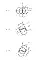
先ず、制御・演算装置42は、3つの復調像の画像データI1,I2,I3の各々をフーリエ変換し、波数空間で表現された3つの復調像の画像データIk1,Ik2,Ik3を得る(ステップS21)。これら復調像の画像データIk1,Ik2,Ik3を図7(A),(B),(C)に示した。FIG. 6 is an operation flowchart regarding the calculation of the control / arithmetic apparatus 42. Here, a description will be given of calculation when image data I1 , I2 , and I3 ofthree demodulated images whose super-resolution directions are different by 120 ° are obtained.
First, the control / arithmetic unit 42 Fourier-transforms each of thethree demodulated image data I1 , I2 , I3 , and the three demodulated image data Ik1 , Ik2,. Ik3 is obtained (step S21). The image data Ik1 , Ik2 , and Ik3 of these demodulated images are shown in FIGS. 7 (A), (B), and (C).
なお、図7(A),(B),(C)において符号Ik+1,Ik-1は、変調された状態で(±1次回折光として)結像光学系LS21によって伝達された成分(±1次変調成分)を示し、符号Ik0は、変調されない状態で(0次回折光として)結像光学系LS21によって伝達された成分(0次変調成分)を示す。また、符号Dbは、超解像の方向(構造化照明の方向)を示し、符号Kは、構造化照明の空間周波数を示す。In FIGS. 7A, 7B, and 7C, symbols Ik + 1 and Ik-1 are components transmitted by the imaging optical system LS21 in a modulated state (as ± first-order diffracted light). The symbol Ik0 indicates a component (0th-order modulation component) transmitted by the imaging optical system LS21 in an unmodulated state (as 0th-order diffracted light). Reference sign Db indicates the super-resolution direction (structured illumination direction), and reference sign K indicates the spatial frequency of structured illumination.
続いて、制御・演算装置42は、3つの復調像の画像データIk1,Ik2,Ik3を、図8に示すとおり波数空間上で合成し、1つの合成画像データIkを得る(ステップS22)。
3つの復調像の画像データIk1,Ik2,Ik3は、互いのデータ範囲を重複させている(共通の空間周波数成分を含んでいる)ので、制御・演算装置42は、合成に当たり、重複したデータについてはそれらの平均値をとり、その平均値を合成画像データIkのデータとする。この平均によって、合成画像データIkの低周波数成分の寄与が大きくなりすぎるのを抑えることで、高周波数成分の相対的な寄与が小さくなるのを防ぐことができる。Subsequently, the control / arithmetic unit 42 synthesizes the image data Ik1 , Ik2 , and Ik3 of the three demodulated images on the wave number space as shown in FIG. 8 to obtain one synthesized image data Ik (step). S22).
Since the image data Ik1 , Ik2 , and Ik3 of the three demodulated images overlap each other's data ranges (including a common spatial frequency component), the control / arithmetic unit 42 overlaps in the synthesis. These data are averaged, and the average value is used as the composite image data Ik data. By suppressing the contribution of the low frequency component of the composite image data Ik from becoming too large by this averaging, it is possible to prevent the relative contribution of the high frequency component from becoming small.
続いて、制御・演算装置42は、合成画像データIkを逆フーリエ変換し、実空間で表現された画像データIを得る。この画像データIは、120°ずつ異なる3方向に亘る標本11の超解像画像を表現する(ステップS23)。制御・演算装置42は、この画像データIを画像表示装置43へ送出し、超解像画像を表示する。
以上、本顕微鏡装置では、図1に示したとおり標本11からの光が回折格子8で再変調され、さらに回折格子8を動かして平均化して不要な回折成分を除去することによって復調像を得ている。したがって、復調演算をしない分だけ復調像の画像データは高速に得られる。Subsequently, the control / arithmetic unit 42 performs inverse Fourier transform on the composite image data Ik to obtain image data I expressed in real space. The image data I represents a super-resolution image of the specimen 11 in three directions that differ by 120 ° (step S23). The control / arithmetic unit 42 sends the image data I to the
As described above, in this microscope apparatus, as shown in FIG. 1, the light from the specimen 11 is remodulated by the
しかも、変調と再変調とに同一の回折格子8の同一の領域が用いられるので、仮にその回折格子8に形状誤差や配置誤差があったとしても、変調のパターンと再変調のパターンとを同一にすることができる。したがって、回折格子8の形状誤差や配置誤差は、復調像の画像データに対しノイズを殆ど与えない。このことは、構造化照明の位相を変化させたときや、構造化照明の方向を変化させたときにも同様に当てはまる。したがって、本顕微鏡装置では超解像画像が高精度に得られる。 In addition, since the same region of the
また、本顕微鏡装置では、標本11の共役面22に回折格子8を配置する都合上、その共役面2に形成された再変調像をリレーしてから撮像素子25で撮像する必要がある。しかし、本顕微鏡装置のリレー光学系LS22などは、上述した条件(条件(i)、(ii)、その他の条件)を満足するので、超解像に必要な情報を確実に取得することができる。 Further, in this microscope apparatus, for the convenience of disposing the
また、本顕微鏡装置では、複数の画像データを合成する際に(図6ステップS22)、それら画像データが共通して有する空間周波数成分を平均化するので、高周波数成分の減衰の少ない良好な超解像画像を得ることができる。
[第2実施形態]
本発明の顕微鏡装置の第2実施形態を説明する。ここでは、第1実施形態との相違点のみ説明する。相違点は、制御・演算装置42の動作にある。In addition, when synthesizing a plurality of pieces of image data (step S22 in FIG. 6), this microscope apparatus averages the spatial frequency components that the image data has in common, so that a high-frequency component with less attenuation can be obtained. A resolution image can be obtained.
[Second Embodiment]
A second embodiment of the microscope apparatus of the present invention will be described. Here, only differences from the first embodiment will be described. The difference is in the operation of the control / arithmetic unit 42.
図9は、本実施形態の制御・演算装置42の制御に関する動作フローチャートである。図9に示すとおり、制御・演算装置42は、復調像の画像データを取得するに当たり、撮像装置25の露光開始(ステップS31)から露光終了(ステップS35)までの期間に、構造化照明の位相を1周期分変化させてから(ステップS32)、さらに構造化照明の方向を変化させて(ステップS34)、再びステップS32における位相変化処理を行う。 FIG. 9 is an operation flowchart relating to the control of the control / arithmetic apparatus 42 of the present embodiment. As shown in FIG. 9, when acquiring the image data of the demodulated image, the control / arithmetic unit 42 is in the phase of the structured illumination during the period from the exposure start (step S31) to the exposure end (step S35) of the
このステップS32における位相変化処理は、構造化照明の方向が予め決められた全方向に設定されるまで(ステップS33YESとなるまで)繰り返され、その後、制御・演算装置42は撮像装置25の露光を終了して画像データを取得する(ステップS35)。
例えば、制御・演算装置42は、ステップS32における位相変化処理を、構造化照明の方向が0°,120°,240°の3方向に設定されるまで繰り返し、構造化照明のパターンの消去された1つの復調像の画像データを取得する。The phase change process in step S32 is repeated until the direction of the structured illumination is set in all predetermined directions (YES in step S33), and then the control / arithmetic unit 42 exposes the
For example, the control / arithmetic unit 42 repeats the phase change process in step S32 until the structured illumination direction is set to three directions of 0 °, 120 °, and 240 °, and the structured illumination pattern is erased. Image data of one demodulated image is acquired.
このようにして取得された復調像の画像データは、構造化照明の位相だけでなく方向の変化中における再変調像の時間積分を示す。よって、この復調像の画像データは、そのまの状態で複数方向に亘る標本11の超解像画像を表す。したがって、本実施形態の制御・演算装置42は、この復調像の画像データをそのまま画像表示装置43へ送出して超解像画像を表示する。 The image data of the demodulated image acquired in this way shows not only the phase of the structured illumination but also the time integration of the remodulated image during a change of direction. Therefore, the demodulated image data represents a super-resolution image of the specimen 11 extending in a plurality of directions as it is. Therefore, the control / arithmetic apparatus 42 according to the present embodiment sends the image data of the demodulated image as it is to the
以上、本実施形態では、撮像装置25の露光期間内に構造化照明の位相だけでなく方向をも変化させるので、超解像画像を第1実施形態よりも高速に得ることができる。
なお、本実施形態では、1次元の構造周期を持つ回折格子8と、その回折格子8を1方向(格子線に直交する方向)に移動させるアクチュエータ40とを使用したが、2次元の周期構造を持つ回折格子と、その回折格子を2方向(格子線に直交する方向)に移動させるアクチュエータとを使用すれば、2方向に亘る超解像画像の情報を略同時に取得することができるので、さらなる高速化を図ることができる。As described above, in the present embodiment, not only the phase of the structured illumination but also the direction is changed within the exposure period of the
In the present embodiment, the
[その他]
なお、上述した各実施形態の顕微鏡装置は、リレーされた再変調像(拡大像24)を撮像装置25で検出したが、拡大像24を接眼レンズを介して肉眼で観察できるように変形されてもよい。
また、上述した各実施形態の顕微鏡装置は、空間変調素子として回折格子を使用したが、入射光束に対し同様の作用をする別の空間変調素子を使用してもよい。[Others]
In addition, although the microscope apparatus of each embodiment mentioned above detected the relayed remodulation image (magnified image 24) with the
In the above-described microscope apparatus of each embodiment, the diffraction grating is used as the spatial modulation element. However, another spatial modulation element that has the same effect on the incident light beam may be used.
例えば、回折格子8の代わりに透過型液晶表示素子などの空間変調素子を用いれば、構造化照明の位相変化及び方向変化を電気的に行うことができ、アクチュエータや回転ステージを用いずに構成し、さらなる高速化を図ることができる。
さらに、上述の各実施形態では蛍光顕微鏡への応用であったが、特にこれに限定されるものではなく、同様に反射顕微鏡を構成することもできる。For example, if a spatial modulation element such as a transmissive liquid crystal display element is used instead of the
Furthermore, in each of the above-described embodiments, the present invention is applied to a fluorescence microscope. However, the present invention is not particularly limited to this, and a reflection microscope can be configured similarly.
Claims (15)
Translated fromJapanese前記中間像の形成面に配置され、前記中間像となる前記光から次数の異なる複数の回折光を発生させる空間変調素子と、
前記複数の回折光を干渉させることにより前記中間像の像を形成するリレー光学系と、
前記結像光学系の光路を共有し、前記空間変調素子のパターンを前記結像光学系の光路を介して前記被観察物上に投影することにより、空間的に変調された照明光で前記被観察物上を照明する照明光学系と、
を備えたことを特徴とする顕微鏡装置。An imaging optical system for forming an intermediate image of light emitted from the object to be observed;
A spatial modulation element that is disposed on the formation surface of the intermediate image and generates a plurality of diffracted lights having different orders from the light that becomes the intermediate image;
A relay optical system that forms an image of the intermediate image by causing the plurality of diffracted lights to interfere with each other;
The optical path of the imaging optical system is shared, and the pattern of the spatial modulation element is projected onto the observation object via the optical path of the imaging optical system, so that the object to be observed isspatially modulated with the illumination light. An illumination optical systemfor illuminating theobservation object ;
A microscope apparatus comprising:
前記空間変調素子のパターンが前記照明光学系によって前記被観察物上に投影されてできる照明パターンの位相を変化させる位相変化手段を更に備えた
ことを特徴とする顕微鏡装置。The microscope apparatus according to claim 1, wherein
A microscope apparatus further comprising phase changing means for changing a phase of an illumination pattern formed by projecting the pattern of the spatial modulation element onto the object to be observed by the illumination optical system.
前記空間変調素子のパターンが前記照明光学系によって前記被観察物上に投影されてできる照明パターンの方向を変化させる方向変化手段を更に備えた
ことを特徴とする顕微鏡装置。In the microscope apparatus according to claim 1 or 2,
A microscope apparatus, further comprising direction changing means for changing a direction of an illumination pattern formed by projecting the pattern of the spatial modulation element onto the object to be observed by the illumination optical system.
前記中間像の像を検出してその像のデータを生成する検出手段と、
前記位相の変化中における前記像の時間積分データを前記検出手段から取得する取得手段と
を更に備えたことを特徴とする顕微鏡装置。The microscope apparatus according to claim 2, wherein
Detecting means for detecting an image of the intermediate image and generating data of the image;
The microscope apparatus further comprising: an acquisition unit that acquires the time integration data of the image during the phase change from the detection unit.
前記空間変調素子のパターンが前記照明光学系によって前記被観察物上に投影されてできる照明パターンの方向を変化させる方向変化手段を更に備え、
前記取得手段は、
前記方向の異なる複数の状態の各々において前記時間積分データを取得する
ことを特徴とする顕微鏡装置。The microscope apparatus according to claim 4,
Direction change means for changing the direction of the illumination pattern formed by projecting the pattern of the spatial modulation element onto the object to be observed by the illumination optical system;
The acquisition means includes
The microscope apparatus characterized in that the time integration data is acquired in each of a plurality of states having different directions.
前記取得された複数の前記時間積分データを合成する演算手段を更に備えた
ことを特徴とする顕微鏡装置。The microscope apparatus according to claim 5,
The microscope apparatus further comprising a calculation unit that synthesizes the plurality of acquired time integration data.
前記演算手段は、
前記複数の時間積分データに共通して含まれる空間周波数成分を平均化して合成する
こと特徴とする顕微鏡装置。The microscope apparatus according to claim 6, wherein
The computing means is
A microscope apparatus characterized by averaging and synthesizing spatial frequency components included in the plurality of time integration data in common.
前記中間像の像を検出してその像のデータを生成する検出手段と、
前記空間変調素子のパターンが前記照明光学系によって前記被観察物上に投影されてできる照明パターンの方向を変化させる方向変化手段と、
前記位相及び前記方向の変化中における前記像の時間積分データを前記検出手段から取得する取得手段と
を更に備えたことを特徴とする顕微鏡装置。The microscope apparatus according to claim 2, wherein
Detecting means for detecting an image of the intermediate image and generating data of the image;
Direction changing means for changing a direction of an illumination pattern formed by projecting the pattern of the spatial modulation element onto the object to be observed by the illumination optical system;
The microscope apparatus further comprising: acquisition means for acquiring time integration data of the image during the change of the phase and the direction from the detection means.
前記中間像の像を検出してその像のデータを生成する検出手段を少なくとも備え、 前記リレー光学系の物体側開口数NA’は、
前記結像光学系の物体側開口数NAobj,前記結像光学系の結像倍率M、定数aに対してNA’>a・NAobj/Mの式を満たし、
前記定数aは、
少なくとも前記検出手段の階調で分解できる限界画像コントラストを考慮しつつ、前記結像光学系及びリレー光学系を介して前記検出手段で検出される前記像のコントラストから逆算して算出されることを特徴とする顕微鏡装置。In the microscope apparatus according to any one of claims 1 to 10,
It comprises at least detection means for detecting the image of the intermediate image and generating data of the image, and the object-side numerical aperture NA ′ of the relay optical system is:
The object side numerical aperture NAobj of the imaging optical system, the imaging magnification M of the imaging optical system, and the constant a satisfy the expression NA ′> a · NAobj / M,
The constant a is
It is calculated by calculating back from the contrast of the image detected by the detection means via the imaging optical system and the relay optical system, considering at least the limit image contrast that can be resolved at the gradation of the detection means. A microscope device characterized.
前記定数aの範囲が、2<aであることを特徴とする顕微鏡装置。The microscope apparatus according to claim 11, wherein
The range of the constant a is 2 <a.
前記空間変調素子のパターンが前記照明光学系によって前記被観察物上に投影されてできる照明パターンの空間周波数の上限は、前記結像光学系及びリレー光学系のMTFを考慮して決定され、前記照明パターンの空間周波数の下限は、超解像効果を考慮して決定されることを特徴とする顕微鏡装置。In the microscope apparatus according to any one of claims 1 to 12,
The upper limit of the spatial frequency of the illumination pattern formed by projecting the spatial modulation element pattern onto the object to be observed by the illumination optical system is determined in consideration of the MTF of the imaging optical system and the relay optical system, and A microscope apparatus, wherein a lower limit of a spatial frequency of an illumination pattern is determined in consideration of a super-resolution effect.
前記空間変調素子のパターンが前記照明光学系によって前記被観察物上に投影されてできる照明パターンの空間周波数kをk=b*(2*NA/λ)で表す場合、0.5<b<0.98であることを特徴とする顕微鏡装置。
但し、NAは開口数、λは波長、bは定数である。The microscope apparatus according to any one of claims 1 to 13,
When the spatial frequency k of the illumination pattern formed by projecting the pattern of the spatial modulation element onto the object to be observed by the illumination optical system is expressed by k = b * (2 * NA / λ), 0.5 <b < A microscope apparatus characterized by being 0.98.
Where NA is the numerical aperture, λ is the wavelength, and b is a constant.
前記空間変調素子が回折格子であって、0次回折光の強度に対する、1次回折光の強度の比e1が、0.37<e1<1.9であることを特徴とする顕微鏡装置。In the microscope apparatus according to any one of claims 1 to 14,
The microscope apparatus, wherein the spatial modulation element is a diffraction grating, and a ratio e1 of the intensity of the first-order diffracted light to the intensity of the 0th-order diffracted light is 0.37 <e1 <1.9.
Priority Applications (1)
| Application Number | Priority Date | Filing Date | Title |
|---|---|---|---|
| JP2007539854AJP4831072B2 (en) | 2005-10-13 | 2006-09-22 | Microscope equipment |
Applications Claiming Priority (6)
| Application Number | Priority Date | Filing Date | Title |
|---|---|---|---|
| JP2005299329 | 2005-10-13 | ||
| JP2005299329 | 2005-10-13 | ||
| JP2006024851 | 2006-02-01 | ||
| JP2006024851 | 2006-02-01 | ||
| PCT/JP2006/318875WO2007043314A1 (en) | 2005-10-13 | 2006-09-22 | Microscope |
| JP2007539854AJP4831072B2 (en) | 2005-10-13 | 2006-09-22 | Microscope equipment |
Publications (2)
| Publication Number | Publication Date |
|---|---|
| JPWO2007043314A1 JPWO2007043314A1 (en) | 2009-04-16 |
| JP4831072B2true JP4831072B2 (en) | 2011-12-07 |
Family
ID=37942565
Family Applications (1)
| Application Number | Title | Priority Date | Filing Date |
|---|---|---|---|
| JP2007539854AExpired - Fee RelatedJP4831072B2 (en) | 2005-10-13 | 2006-09-22 | Microscope equipment |
Country Status (4)
| Country | Link |
|---|---|
| US (1) | US8081378B2 (en) |
| EP (1) | EP1936422A4 (en) |
| JP (1) | JP4831072B2 (en) |
| WO (1) | WO2007043314A1 (en) |
Families Citing this family (41)
| Publication number | Priority date | Publication date | Assignee | Title |
|---|---|---|---|---|
| US8189191B2 (en)* | 2005-07-26 | 2012-05-29 | Tufts University | Spectroscopic imaging microscopy |
| US7872798B2 (en)* | 2005-10-11 | 2011-01-18 | Nikon Corporation | Microscopic apparatus and observing method |
| US9234845B2 (en) | 2006-10-19 | 2016-01-12 | Olympus Corporation | Microscope with reflecting fluorescence illumination optical system |
| EP2136233B1 (en)* | 2007-04-12 | 2013-06-12 | Nikon Corporation | Microscope device |
| EP2171516A1 (en)* | 2007-07-06 | 2010-04-07 | National University of Signapore | Fluorescence focal modulation microscopy system and method |
| DE102007047466A1 (en)* | 2007-09-28 | 2009-04-02 | Carl Zeiss Microimaging Gmbh | Method and arrangement for optically detecting an illuminated sample |
| DE102007047460A1 (en) | 2007-09-28 | 2009-04-09 | Carl Zeiss Meditec Ag | Apparatus and method for examining the ocular fundus, in particular the photoreceptors |
| DE102007047468A1 (en)* | 2007-09-28 | 2009-04-02 | Carl Zeiss Microimaging Gmbh | Method and arrangement for optically detecting an illuminated sample |
| FR2922658B1 (en)* | 2007-10-18 | 2011-02-04 | Centre Nat Rech Scient | STRUCTURED ILLUMINATION SYSTEM OF A SAMPLE |
| US8537461B2 (en)* | 2007-11-26 | 2013-09-17 | Carl Zeiss Microimaging Gmbh | Method and configuration for the optical detection of an illuminated specimen |
| DE102009024941A1 (en)* | 2009-06-09 | 2010-12-23 | Carl Zeiss Surgical Gmbh | Lighting device and medical-optical observation device |
| WO2011005239A1 (en)* | 2009-07-08 | 2011-01-13 | Freescale Semiconductor, Inc. | Device for forming a high-resolution image, imaging system, and method for deriving a high-spatial-resolution image |
| CN102597845B (en)* | 2009-11-02 | 2016-06-29 | 奥林巴斯株式会社 | Beam splitter apparatus, light supply apparatus and scanning observation device |
| WO2011119678A2 (en) | 2010-03-23 | 2011-09-29 | California Institute Of Technology | Super resolution optofluidic microscopes for 2d and 3d imaging |
| EP2565697B1 (en)* | 2010-04-26 | 2020-07-01 | Nikon Corporation | Structural illumination microscope device |
| DE102010041794A1 (en)* | 2010-09-30 | 2012-04-05 | Carl Zeiss Microlmaging Gmbh | Microscope system, microscopy method and computer program product |
| JP5412394B2 (en) | 2010-09-30 | 2014-02-12 | オリンパス株式会社 | Sample observation equipment |
| US9426429B2 (en) | 2010-10-26 | 2016-08-23 | California Institute Of Technology | Scanning projective lensless microscope system |
| US9643184B2 (en) | 2010-10-26 | 2017-05-09 | California Institute Of Technology | e-Petri dishes, devices, and systems having a light detector for sampling a sequence of sub-pixel shifted projection images |
| US9569664B2 (en)* | 2010-10-26 | 2017-02-14 | California Institute Of Technology | Methods for rapid distinction between debris and growing cells |
| CN103477209B (en)* | 2011-03-01 | 2016-03-30 | 通用电气医疗集团生物科学公司 | For the system and method for phase control of throwing light in fluorescent microscope |
| US9343494B2 (en) | 2011-03-03 | 2016-05-17 | California Institute Of Technology | Light guided pixel configured for emissions detection and comprising a guide layer with a wavelength selective filter material and a light detector layer |
| WO2013001805A1 (en)* | 2011-06-29 | 2013-01-03 | 株式会社ニコン | Structured illumination optical system and structured illumination microscope device |
| JP5743209B2 (en)* | 2011-06-29 | 2015-07-01 | 横河電機株式会社 | Microscope equipment |
| DE102011114500B4 (en) | 2011-09-29 | 2022-05-05 | Fei Company | microscope device |
| JP5562919B2 (en)* | 2011-09-30 | 2014-07-30 | オリンパス株式会社 | Super-resolution observation device |
| US9599805B2 (en) | 2011-10-19 | 2017-03-21 | National Synchrotron Radiation Research Center | Optical imaging system using structured illumination |
| JP6000554B2 (en)* | 2012-01-24 | 2016-09-28 | オリンパス株式会社 | Microscope system |
| US9952418B2 (en) | 2013-03-15 | 2018-04-24 | Intelligent Imaging Innovations, Inc. | Multi-channel simultaneous photostimulation |
| CN103256888B (en)* | 2013-05-09 | 2015-12-02 | 哈尔滨工业大学 | A kind of super-resolution moving grating confocal imaging apparatus and method |
| JP6264377B2 (en)* | 2013-07-17 | 2018-01-24 | 株式会社ニコン | Structured illumination device and structured illumination microscope device |
| WO2015052920A1 (en)* | 2013-10-07 | 2015-04-16 | 株式会社ニコン | Structured illumination device and structured illumination microscope device |
| US9182583B2 (en)* | 2013-11-15 | 2015-11-10 | Mitutoyo Corporation | Structured illumination microscopy optical arrangement including projection artifact supression element |
| CN105814402B (en)* | 2013-11-27 | 2018-11-06 | 苏州大学 | The super-resolution micro imaging method and system of continuously adjustable Structured Illumination |
| JP6635052B2 (en)* | 2015-02-05 | 2020-01-22 | 株式会社ニコン | Structured illumination microscope and observation method |
| WO2016199179A1 (en) | 2015-06-08 | 2016-12-15 | 株式会社ニコン | Structured illumination microscope system, method, and program |
| CN105301794B (en)* | 2015-10-30 | 2017-08-25 | 中国科学院遗传与发育生物学研究所 | Super-resolution imaging device for fast moving objects |
| RU172410U1 (en)* | 2017-02-03 | 2017-07-07 | Федеральное государственное унитарное предприятие "Всероссийский научно-исследовательский институт автоматики им. Н.Л. Духова" (ФГУП "ВНИИА") | Device for obtaining microscopic images of distant objects based on an optical transfer system |
| DE102017108873A1 (en)* | 2017-04-26 | 2018-10-31 | Carl Zeiss Microscopy Gmbh | Phase-contrast imaging with transfer function |
| US10429315B2 (en)* | 2017-07-18 | 2019-10-01 | Samsung Electronics Co., Ltd. | Imaging apparatus and imaging method |
| EP3752879A1 (en) | 2018-02-12 | 2020-12-23 | Intelligent Imaging Innovations, Inc. | Tiling light sheet selective plane illumination microscopy using discontinuous light sheets |
Citations (3)
| Publication number | Priority date | Publication date | Assignee | Title |
|---|---|---|---|---|
| JPH1164797A (en)* | 1997-08-12 | 1999-03-05 | Ishikawajima Harima Heavy Ind Co Ltd | Phase difference pinhole type optical element and confocal microscope using the same |
| JP2002311335A (en)* | 2001-04-12 | 2002-10-23 | Nikon Corp | Grating illumination microscope |
| JP2003262798A (en)* | 2002-03-12 | 2003-09-19 | Olympus Optical Co Ltd | microscope |
Family Cites Families (11)
| Publication number | Priority date | Publication date | Assignee | Title |
|---|---|---|---|---|
| DE3826317C1 (en)* | 1988-08-03 | 1989-07-06 | Ernst Leitz Wetzlar Gmbh, 6330 Wetzlar, De | |
| US5671085A (en)* | 1995-02-03 | 1997-09-23 | The Regents Of The University Of California | Method and apparatus for three-dimensional microscopy with enhanced depth resolution |
| US5969855A (en)* | 1995-10-13 | 1999-10-19 | Olympus Optical Co., Ltd. | Microscope apparatus |
| US6020963A (en)* | 1996-06-04 | 2000-02-01 | Northeastern University | Optical quadrature Interferometer |
| ATE236412T1 (en)* | 1997-10-22 | 2003-04-15 | Max Planck Gesellschaft | PROGRAMMABLE SPACIAL LIGHT MODULATED MICROSCOPE AND MICROSCOPY METHOD |
| JPH11242189A (en) | 1997-12-25 | 1999-09-07 | Olympus Optical Co Ltd | Method and device for forming image |
| ATE493683T1 (en) | 2001-04-07 | 2011-01-15 | Zeiss Carl Microimaging Gmbh | METHOD AND ARRANGEMENT FOR DEPTH-RESOLVED OPTICAL DETECTION OF A SAMPLE |
| JP4020714B2 (en)* | 2001-08-09 | 2007-12-12 | オリンパス株式会社 | microscope |
| DE10254139A1 (en)* | 2002-11-15 | 2004-05-27 | Carl Zeiss Jena Gmbh | Method and arrangement for the depth-resolved optical detection of a sample |
| JP4239166B2 (en)* | 2002-12-27 | 2009-03-18 | 関西ティー・エル・オー株式会社 | Multilayer observation type optical microscope and multilayer observation unit |
| US7075058B2 (en)* | 2003-03-28 | 2006-07-11 | The United States Of America As Represented By The United States Department Of Energy | Photothermal imaging scanning microscopy |
- 2006
- 2006-09-22JPJP2007539854Apatent/JP4831072B2/ennot_activeExpired - Fee Related
- 2006-09-22EPEP06798263Apatent/EP1936422A4/ennot_activeWithdrawn
- 2006-09-22WOPCT/JP2006/318875patent/WO2007043314A1/enactiveApplication Filing
- 2006-09-22USUS11/887,822patent/US8081378B2/ennot_activeExpired - Fee Related
Patent Citations (3)
| Publication number | Priority date | Publication date | Assignee | Title |
|---|---|---|---|---|
| JPH1164797A (en)* | 1997-08-12 | 1999-03-05 | Ishikawajima Harima Heavy Ind Co Ltd | Phase difference pinhole type optical element and confocal microscope using the same |
| JP2002311335A (en)* | 2001-04-12 | 2002-10-23 | Nikon Corp | Grating illumination microscope |
| JP2003262798A (en)* | 2002-03-12 | 2003-09-19 | Olympus Optical Co Ltd | microscope |
Also Published As
| Publication number | Publication date |
|---|---|
| WO2007043314A1 (en) | 2007-04-19 |
| US8081378B2 (en) | 2011-12-20 |
| EP1936422A4 (en) | 2013-01-16 |
| EP1936422A1 (en) | 2008-06-25 |
| JPWO2007043314A1 (en) | 2009-04-16 |
| US20090268280A1 (en) | 2009-10-29 |
Similar Documents
| Publication | Publication Date | Title |
|---|---|---|
| JP4831072B2 (en) | Microscope equipment | |
| JP4835750B2 (en) | Microscope equipment | |
| JP5136422B2 (en) | Microscope device and image processing method | |
| JP5412394B2 (en) | Sample observation equipment | |
| US8019136B2 (en) | Optical sectioning microscopy | |
| JP2007199572A (en) | Microscope equipment | |
| JP2007199397A (en) | Microscope equipment | |
| JP4123305B2 (en) | Image creation method and microscope apparatus | |
| US6239909B1 (en) | Image-forming method and image-forming apparatus | |
| JP4844137B2 (en) | Microscope equipment | |
| US7385709B2 (en) | Microscopy imaging apparatus and method for generating an image | |
| US20220076379A1 (en) | Method for super-resolution evaluation of microscope images illuminated in a structured manner and microscope having structured illumination | |
| TWI414818B (en) | Wide-field super-resolution optical sectioning microscopy using a spatial light modulator | |
| JPWO2019053768A1 (en) | Microscope and observation method | |
| WO2006109561A1 (en) | Microscope imaging apparatus and method | |
| Rubio-Oliver et al. | Cepstrum-based interferometric microscopy with rolling-shutter cameras | |
| JP2002196253A (en) | Interference fringe projection optical system and microscope using this optical system |
Legal Events
| Date | Code | Title | Description |
|---|---|---|---|
| A131 | Notification of reasons for refusal | Free format text:JAPANESE INTERMEDIATE CODE: A131 Effective date:20100706 | |
| A521 | Request for written amendment filed | Free format text:JAPANESE INTERMEDIATE CODE: A523 Effective date:20100901 | |
| TRDD | Decision of grant or rejection written | ||
| A01 | Written decision to grant a patent or to grant a registration (utility model) | Free format text:JAPANESE INTERMEDIATE CODE: A01 Effective date:20110823 | |
| A01 | Written decision to grant a patent or to grant a registration (utility model) | Free format text:JAPANESE INTERMEDIATE CODE: A01 | |
| A61 | First payment of annual fees (during grant procedure) | Free format text:JAPANESE INTERMEDIATE CODE: A61 Effective date:20110905 | |
| R150 | Certificate of patent or registration of utility model | Ref document number:4831072 Country of ref document:JP Free format text:JAPANESE INTERMEDIATE CODE: R150 Free format text:JAPANESE INTERMEDIATE CODE: R150 | |
| FPAY | Renewal fee payment (event date is renewal date of database) | Free format text:PAYMENT UNTIL: 20140930 Year of fee payment:3 | |
| FPAY | Renewal fee payment (event date is renewal date of database) | Free format text:PAYMENT UNTIL: 20140930 Year of fee payment:3 | |
| R250 | Receipt of annual fees | Free format text:JAPANESE INTERMEDIATE CODE: R250 | |
| R250 | Receipt of annual fees | Free format text:JAPANESE INTERMEDIATE CODE: R250 | |
| R250 | Receipt of annual fees | Free format text:JAPANESE INTERMEDIATE CODE: R250 | |
| R250 | Receipt of annual fees | Free format text:JAPANESE INTERMEDIATE CODE: R250 | |
| R250 | Receipt of annual fees | Free format text:JAPANESE INTERMEDIATE CODE: R250 | |
| R250 | Receipt of annual fees | Free format text:JAPANESE INTERMEDIATE CODE: R250 | |
| R250 | Receipt of annual fees | Free format text:JAPANESE INTERMEDIATE CODE: R250 | |
| R250 | Receipt of annual fees | Free format text:JAPANESE INTERMEDIATE CODE: R250 | |
| R250 | Receipt of annual fees | Free format text:JAPANESE INTERMEDIATE CODE: R250 | |
| LAPS | Cancellation because of no payment of annual fees |