JP4830817B2 - Optical scanning optical device - Google Patents
Optical scanning optical deviceDownload PDFInfo
- Publication number
- JP4830817B2 JP4830817B2JP2006322610AJP2006322610AJP4830817B2JP 4830817 B2JP4830817 B2JP 4830817B2JP 2006322610 AJP2006322610 AJP 2006322610AJP 2006322610 AJP2006322610 AJP 2006322610AJP 4830817 B2JP4830817 B2JP 4830817B2
- Authority
- JP
- Japan
- Prior art keywords
- optical
- main scanning
- motors
- motor
- scanning direction
- Prior art date
- Legal status (The legal status is an assumption and is not a legal conclusion. Google has not performed a legal analysis and makes no representation as to the accuracy of the status listed.)
- Expired - Fee Related
Links
- 230000003287optical effectEffects0.000titleclaimsdescription74
- 238000003384imaging methodMethods0.000claimsdescription26
- 230000004907fluxEffects0.000claimsdescription4
- 239000000463materialSubstances0.000description6
- 230000006866deteriorationEffects0.000description3
- 239000003086colorantSubstances0.000description2
- 239000002131composite materialSubstances0.000description2
- 238000001514detection methodMethods0.000description2
- 238000010586diagramMethods0.000description2
- 230000002093peripheral effectEffects0.000description2
- 230000015556catabolic processEffects0.000description1
- 238000006731degradation reactionMethods0.000description1
- 238000012423maintenanceMethods0.000description1
- 238000000034methodMethods0.000description1
- 239000000758substrateSubstances0.000description1
- 238000011144upstream manufacturingMethods0.000description1
Images


Landscapes
- Laser Beam Printer (AREA)
- Mechanical Optical Scanning Systems (AREA)
- Facsimile Scanning Arrangements (AREA)
Description
Translated fromJapanese本発明は、光走査光学装置、特に、電子写真法によるタンデム方式の画像形成装置にプリントヘッドとして搭載される光走査光学装置に関する。 The present invention relates to an optical scanning optical device, and more particularly, to an optical scanning optical device mounted as a print head in a tandem image forming apparatus using electrophotography.
電子写真法によるタンデム方式のプリンタや複写機などの画像形成装置においては、色の3原色(Y,M,C)と黒色(K)の画像を平行に配置された四つの感光体上に形成し、各画像を中間転写ベルト上に1次転写して合成し、さらに記録材上に2次転写するようにしている。この場合、色ずれを防止するために、四つの画像が中間転写ベルト上で精度よく合成されるように位置合わせを高精度に調整する必要がある。 In an image forming apparatus such as an electrophotographic tandem printer or copier, three primary colors (Y, M, C) and black (K) are formed on four photoconductors arranged in parallel. Each image is primarily transferred onto the intermediate transfer belt and synthesized, and then further transferred onto the recording material. In this case, in order to prevent color misregistration, it is necessary to adjust the alignment with high accuracy so that the four images are accurately synthesized on the intermediate transfer belt.
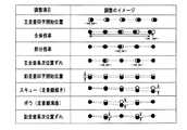
色ずれの調整の項目は、図11に示すように(白丸は設計上の露光位置、黒丸はずれた露光位置をそれぞれ示す)、主走査印字開始位置、全体倍率、部分倍率、主走査高次位置ずれ、副走査印字開始位置、スキュー(走査線傾き)、ボウ(走査線湾曲)、副走査高次位置ずれ、を挙げることができる。 The items of color misregistration adjustment are as shown in FIG. 11 (the white circle indicates the design exposure position and the exposure position shifted from the black circle, respectively), the main scanning print start position, the overall magnification, the partial magnification, and the main scanning higher-order position. Deviation, sub-scan printing start position, skew (scan line inclination), bow (scan line curve), and sub-scan higher-order position deviation can be mentioned.
このうち、スキューの調整に関しては、特許文献1,2に記載のように、ポリゴンミラーで偏向された各光束の光路を折り曲げるミラーの主走査方向の傾きをモータにて補正する機構が記載されている。しかしながら、モータは駆動時に発熱するために、モータがハウジングの一方の側に偏して配置されていると、ハウジング内の温度分布が不均衡になって結像レンズなどハウジング内に配置されている光学素子に熱歪みが発生する。そして、光学素子が歪んだりすると、各色の画像にピッチむらやジッタが発生してレジスト性能が劣化するおそれを有している。
そこで、本発明の目的は、露光位置調整用モータの発熱に起因するレジスト性能の劣化を効果的に防止できる光走査光学装置を提供することにある。 SUMMARY OF THE INVENTION Accordingly, an object of the present invention is to provide an optical scanning optical device that can effectively prevent deterioration of resist performance caused by heat generated by an exposure position adjusting motor.
以上の目的を達成するため、本発明に係る光走査光学装置は、
複数の光源から放射された各光束を偏向器の同一面で主走査方向に偏向し、偏向された各光束を主走査方向と直交する方向に所定の間隔で配列された複数の感光体上に結像させる複数の光路を備えた光走査光学装置において、
前記複数の光路には、それぞれ、前記光束を各感光体上に結像させる結像素子と、前記光束を各感光体上に導くミラーとが含まれ、
前記各部材を保持するハウジングと、前記光束が前記感光体上を露光する位置を調整するために前記結像素子又は前記ミラーを変位させるモータと、を備え、
前記モータは前記感光体の配列方向に複数配置されており、
前記複数のモータは前記結像素子又は前記ミラーの主走査方向の片側に配置され、該モータのうち少なくとも一つは主走査方向において他のモータとは対向する側に配置されていること、
を特徴とする。In order to achieve the above object, an optical scanning optical device according to the present invention includes:
The light beams emitted from a plurality of light sources are deflected in the main scanning direction on the same surface of the deflector, and the deflected light beams are arranged on a plurality of photoconductors arranged at predetermined intervals in a direction orthogonal to the main scanning direction. In an optical scanning optical device having a plurality of optical paths to be imaged,
Each of the plurality of optical paths includes an image forming element that forms an image of the light flux on each photoconductor, and a mirror that guides the light flux on each photoconductor,
Wherein comprises a housing for holding the respective members, and a motorfor displacing the imaging element or the mirror to the light beam to adjust the position of exposing the over said photosensitive member,
A plurality of the motors are arranged in the arrangement direction of the photoconductors,
The plurality of motorsare arranged on one side of the imaging element or the mirror in the main scanning direction, and at least one of the motors is arranged on the side facing the other motors in the main scanning direction;
It is characterized by.
本発明に係る光走査光学装置において、露光位置調整用モータは結像素子又はミラーの主走査方向の片側に配置され、該モータは少なくとも一つが主走査方向において他のモータとは対向する側に配置されているため、モータ駆動時の発熱によるハウジング内の温度分布が一方の側に偏ることが防止される。それゆえ、ハウジング内に配置されている結像レンズなどの光学素子に熱歪みが生じることがなく、4色の画像のレジスト性能の劣化を抑えることができる。In the optical scanning optical apparatus according to the present invention, the exposure position adjusting motoris arranged on one side of the imaging element or mirror in the main scanning direction, and at least one of the motors is on the side facing the other motor in the main scanning direction. Therefore, the temperature distribution in the housing due to heat generated when the motor is driven is prevented from being biased to one side. Therefore, thermal distortion does not occur in an optical element such as an imaging lens arranged in the housing, and deterioration of resist performance of four-color images can be suppressed.
露光位置調整用モータは、例えば、感光体上を露光する走査線の傾き(スキュー)を調整するためのものである。 The exposure position adjusting motor is, for example, for adjusting the inclination (skew) of the scanning line for exposing the photosensitive member.
本発明に係る光走査光学装置においては、複数の露光調整用モータは隣接して配置された前記感光体に対応するものどうしが主走査方向において互いに対向する側に配置されていることが好ましい。温度分布の偏りを効果的に解消することができる。In the optical scanning optical apparatus according to the present invention, it is preferable that the plurality of exposure adjustment motorscorresponding to the photoconductors arranged adjacentto each other are arranged on opposite sides in the main scanning direction. The uneven temperature distribution can be effectively eliminated.
以下、本発明に係る光走査光学装置の実施例について、添付図面を参照して説明する。 Embodiments of an optical scanning optical device according to the present invention will be described below with reference to the accompanying drawings.
(画像形成装置の全体構成、図1参照)
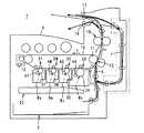
図1に、本発明に係る光走査光学装置を搭載したカラープリンタ1の概略構成を示す。このカラープリンタ1は、タンデム方式で4色の画像を合成するように構成されている。即ち、四つの画像形成ステーション2(2Y,2M,2C,2K)の直上に中間転写ベルト10が配置され、直下に光走査光学装置20が配置されている。各画像形成ステーション2には、それぞれ、感光体ドラム3(3Y,3M,3C,3K)、現像器4(4Y,4M,4C,4K)や図示しない帯電器、残留トナーのクリーナなどが配置されている。なお、黒色の画像を形成するための画像形成ステーション2Kは大型に構成され、使用頻度の高いモノクロ画像を高速で形成できるようにしている。(Overall configuration of image forming apparatus, see FIG. 1)
FIG. 1 shows a schematic configuration of a color printer 1 equipped with an optical scanning optical device according to the present invention. The color printer 1 is configured to synthesize four color images in a tandem manner. That is, the
光走査光学装置20は、Y,M,C,Kの画像データに基づいて放射される光束By,Bm,Bc,Bkによって各感光体ドラム3上に画像(静電潜像)を形成する。この潜像はトナーによって可視像化される。このような電子写真プロセスは周知であり、その説明は省略する。 The optical scanning
中間転写ベルト10は、駆動ローラ11及び支持ローラ12に無端状に張り渡され、矢印Y方向への回転に基づいて前記各感光体ドラム3上に形成された各色のトナー画像が順次1次転写され、合成される。また、中間転写ベルト10上に形成された画像(調整用トナーパターン)を読み取るため、黒色の画像形成ステーション2Kの直後に光学センサ71が配置されている。 The
記録材は、自動給紙カセット5に収納されており、1枚ずつ所定のタイミングで給紙され、通紙経路6を経由して中間転写ベルト10から2次転写位置13にて合成トナー画像を2次転写され、定着装置15でトナーの加熱定着を施された後、排出ローラ16から排紙部9上に排出される。一方、両面プリントの際、記録材はスイッチバックローラ17からプリンタ1の外方に搬送され、スイッチバックされて反転経路7を経由して2次転写位置13に戻される。ここで裏面にトナー画像を2次転写された記録材は排出ローラ16から排紙部9上に排出されることになる。 The recording material is stored in the automatic
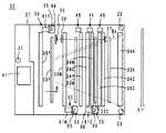
(光走査光学装置の概略構成、図2〜図4参照)
図2は一実施例である光走査光学装置20の断面図、図3は平面図、図4は底面図である。この光走査光学装置20は、光源部21と、ポリゴンミラー40と第1及び第2結像レンズ31,32と、各光路ごとに設けた折返しミラー34,35,36及び第3結像レンズ33と、これらの部材を保持するハウジング27とで構成されている。光源部21は、レーザダイオード22(22Y,22M,22C,22K)と、合成ミラー23(23Y,23M,23C)と、折返しミラー24と、シリンドリカルレンズ25とで構成され、プレート26に搭載されている。(Schematic configuration of optical scanning optical device, see FIGS. 2 to 4)
2 is a cross-sectional view of the optical scanning
レーザダイオード22Kから放射された光束は折返しミラー24に直接導かれる。また、レーザダイオード22C,22M,22Yからそれぞれ放射された光束は、合成ミラー23C,23M,23Yでそれぞれ反射し、折返しミラー24に導かれる。折返しミラー24で反射された各光束はシリンドリカルレンズ25で副走査方向Z(図2参照)にほぼ平行に集光され、ポリゴンミラー40の同一面に副走査方向Zに所定の角度を有して導かれる。 The light beam emitted from the
これらの光束はポリゴンミラー40の回転に基づいて主走査方向Xに等角速度で偏向され、第1及び第2結像レンズ31,32を透過した後、光束Bkは第3結像レンズ33Kを透過して折返しミラー34Kで反射され、感光体ドラム3K上を露光/走査する。光束Bcは折返しミラー34C,35Cで反射されて第3結像レンズ33Cを透過し、さらに折返しミラー36Cで反射され、感光体ドラム3C上を露光/走査する。光束Bmは折返しミラー34Mで反射されて第3結像レンズ33Mを透過し、さらに折返しミラー35Mで反射され、感光体ドラム3M上を露光/走査する。光束Byは折返しミラー34Yで反射されて第3結像レンズ33Yを透過し、さらに折返しミラー35Yで反射され、感光体ドラム3Y上を露光/走査する。 These light beams are deflected at a constant angular velocity in the main scanning direction X based on the rotation of the
ポリゴンミラー40は、図2に示すように、プレート44に固定したモータ42に取り付けられている。プレート44はさらに基板41及び放熱板43が取り付けられている。 As shown in FIG. 2, the
また、各感光体ドラム3上での各走査線の書出し位置を検出するため、即ち、主走査同期信号を得るため、ポリゴンミラー40で偏向された光束Bkの主走査方向上流側光束は、図3に示すように、検出用ミラー37で反射されてレンズ38で集光され、同期信号検出用受光センサ39に入射する。 Further, in order to detect the writing position of each scanning line on each photosensitive drum 3, that is, to obtain a main scanning synchronization signal, the upstream side beam in the main scanning direction of the beam Bk deflected by the
さらに、色ずれ調整(レジスト調整)として、図3に示すように、部分倍率調整機構45とスキュー調整機構50が設置されている。スキュー調整機構50は駆動源としてブラケット59を介してハウジング27に固定されたステッピングモータ51(51Y,51M,51C)を備え、その詳細は図9及び図10を参照して後述する。なお、部分倍率調整機構45は手動にて調整するものであり、その説明は省略する。 Further, as shown in FIG. 3, a partial
(色ずれ調整、図11及び図12参照)
色ずれ(レジスト)調整は、各画像形成ステーション2にて図12に示すトナーパターンPy,Pm,Pc,Pkを形成して中間転写ベルト10上に1次転写し、このトナーパターンPy〜Pkを光学センサ71にて検出することにより、図11に示した各調整項目の全てあるいはその一部の項目を調整する。(Color misregistration adjustment, see FIGS. 11 and 12)
For color misregistration (registration) adjustment, toner patterns Py, Pm, Pc, and Pk shown in FIG. 12 are formed at each image forming station 2 and primarily transferred onto the
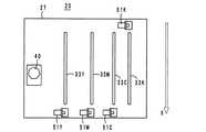
(スキュー調整用モータの配置、図3、図5〜図8参照)
走査線の傾き(スキュー)の調整は、光束Bkを基準として光束Bc,Bm,Byに対して行われる。従って、スキュー調整用モータ51は光束Bkに対して配置された第3レンズ33Kに対しては設置されておらず、光束Bc,Bm,Byに対して配置された第3レンズ33C,33M,33Yに対して設置されている。(Disposition of skew adjustment motor, see FIGS. 3, 5 to 8)
The inclination (skew) of the scanning line is adjusted for the light beams Bc, Bm, and By using the light beam Bk as a reference. Therefore, the
ハウジング27内において、スキュー調整用モータ51は、各感光体ドラム3の配列方向(図3の矢印B参照)に配置され、配置の第1例は、図3に示すように、結像レンズ33Yを変位させるモータ51Yは主走査方向Xにおける一方側に配置され、結像レンズ33M,33Cを変位させるモータ51M,51Cは主走査方向Xにおける他方の側に配置されている。 In the
なお、ハウジング27はカラープリンタ1の図示しないフレームに、3箇所の固定点Z1,Z2,Z3により、例えば、ねじ止めにより固定されている。 The
本光走査光学装置20において、色ずれ調整は、例えば、プリンタ1を立ち上げたときを含めて、連続的に搬送される先行する記録材の後端と後続の記録材の先端が2次転写位置13を通過する間でも行われる。スキューが発生していれば、モータ51を駆動して第3レンズ33を変位させ、スキューを調整する。 In the present optical scanning
スキュー調整のためにモータ51を駆動するとモータ51の発熱によりハウジング27内の温度が上昇する。本実施例においては、三つのモータのうち一つのモータ51Yを一方の側に配置したため、ハウジング27内の温度分布が他方の側に偏ることが防止される。これにて、ハウジング27内に配置されている結像レンズ31,32,33などの光学素子の熱歪みが防止され、画像のレジスト性能の劣化を抑えることができる。 When the
図5に、スキュー調整用モータ51の配置の第2例を示し、結像レンズ33Mを変位させるモータ51Mを主走査方向Xにおける一方の側に配置し、結像レンズ33Y,33Cを変位させるモータ51Y,51Cを主走査方向Xにおける他方の側に配置した例である。 FIG. 5 shows a second example of the arrangement of the
なお、光束Bkに対してもスキュー調整を行うようにし、四つのモータ51を設けてもよい。図6に、四つのモータ51を設けた場合の配置の第3例を示す。この第3例では、結像レンズ33M,33Kを変位させるモータ51M、51Kを主走査方向Xにおける一方側に配置し、結像レンズ33Y,33Cを変位させるモータ51Y,51Cを主走査方向Xにおける他方の側に配置した。 Note that the skew adjustment may be performed on the light beam Bk, and the four
図7に、モータ51の配置の第4例を示し、結像レンズ33Y,33Kを変位させるモータ51Y,51Kを主走査方向Xにおける一方の側に配置し、結像レンズ33M,33Cを変位させるモータ51M,51Cを主走査方向Xにおける他方の側に配置した。 FIG. 7 shows a fourth example of the arrangement of the
図8に、モータ51の配置の第5例を示し、結像レンズ33Kを変位させるモータ51Kを主走査方向Xにおける一方の側に配置し、結像レンズ33Y,33M,33Cを変位させるモータ51Y,51M,51Cを主走査方向Xにおける他方の側に配置した。 FIG. 8 shows a fifth example of the arrangement of the
前記第2例〜第5例においても、モータ51の発熱によるハウジング27内の温度分布が一方の側又は他方の側に偏ることが防止され、画像のレジスト性能の劣化を抑えることができる。 Also in the second to fifth examples, it is possible to prevent the temperature distribution in the
(スキュー調整機構、図9及び図10参照)
ここで、走査線の傾き(スキュー)を調整するためのスキュー調整機構50について説明する。即ち、第3レンズ33は、図10に示すように、レンズホルダ52に保持され、このレンズホルダ52は一端部で矢印F方向に揺動可能にピン53にて支持されている。さらに、レンズホルダ52の他端部には受け部材58が固定され、図9に示すように、この受け部材58はハウジング27の傾斜面27gに板ばね54にて押圧され、かつ、矢印F方向にスライド自在に取り付けられている。ステッピングモータ51の出力軸51aに固定したウォームギヤ55はウォームホイール56に噛合し、該ウォームホイール56と同軸に固定した偏芯カム57の外周面が受け部材58の底面に当接している。(Skew adjustment mechanism, see FIGS. 9 and 10)
Here, the
ステッピングモータ51は、図12に示したトナーパターンPy〜Pkから検出されたスキューの状態に応じてその回転を制御され、ウォームギヤ55の回転がウォームホイール56から偏芯カム57に伝達され、偏芯カム57の外周面が受け部材58を押上げることでホルダ52とともに第3レンズ33を変位させてスキューを調整する。また、ホルダ52は図示しないばね部材により下方へ強制的に復帰するように付勢されている。 The rotation of the stepping
(他の実施例)
なお、本発明に係る光走査光学装置は前記実施例に限定するものではなく、その要旨の範囲内で種々に変更することができる。(Other examples)
The optical scanning optical device according to the present invention is not limited to the above-described embodiments, and can be variously modified within the scope of the gist thereof.
特に、ハウジングの細部の構成、光源部の構成の詳細、四つの光路を形成する各種光学素子の構成や配置は任意である。また、スキュー調整は、第3レンズを変位させる以外に、折返しミラーなどを変位させることで行うようにしてもよい。 In particular, the detailed configuration of the housing, the detailed configuration of the light source unit, and the configuration and arrangement of various optical elements forming the four optical paths are arbitrary. The skew adjustment may be performed by displacing a folding mirror or the like in addition to displacing the third lens.
3(3Y,3M,3C,3K)…感光体ドラム
20…光走査光学装置
21…光源部
27…ハウジング
31,32,33…結像レンズ
34,35,36…折返しミラー
40…ポリゴンミラー
51(51Y,51M,51C,51K)…スキュー調整用モータ
X…主走査方向3 (3Y, 3M, 3C, 3K) ...
Claims (3)
Translated fromJapanese前記複数の光路には、それぞれ、前記光束を各感光体上に結像させる結像素子と、前記光束を各感光体上に導くミラーとが含まれ、
前記各部材を保持するハウジングと、前記光束が前記感光体上を露光する位置を調整するために前記結像素子又は前記ミラーを変位させるモータと、を備え、
前記モータは前記感光体の配列方向に複数配置されており、
前記複数のモータは前記結像素子又は前記ミラーの主走査方向の片側に配置され、該モータのうち少なくとも一つは主走査方向において他のモータとは対向する側に配置されていること、
を特徴とする光走査光学装置。The light beams emitted from a plurality of light sources are deflected in the main scanning direction on the same surface of the deflector, and the deflected light beams are arranged on a plurality of photoconductors arranged at predetermined intervals in a direction orthogonal to the main scanning direction. In an optical scanning optical device having a plurality of optical paths to be imaged,
Each of the plurality of optical paths includes an image forming element that forms an image of the light flux on each photoconductor, and a mirror that guides the light flux on each photoconductor,
Wherein comprises a housing for holding the respective members, and a motorfor displacing the imaging element or the mirror to the light beam to adjust the position of exposing the over said photosensitive member,
A plurality of the motors are arranged in the arrangement direction of the photoconductors,
The plurality of motorsare arranged on one side of the imaging element or the mirror in the main scanning direction, and at least one of the motors is arranged on the side facing the other motors in the main scanning direction;
An optical scanning optical device.
Priority Applications (1)
| Application Number | Priority Date | Filing Date | Title |
|---|---|---|---|
| JP2006322610AJP4830817B2 (en) | 2006-11-29 | 2006-11-29 | Optical scanning optical device |
Applications Claiming Priority (1)
| Application Number | Priority Date | Filing Date | Title |
|---|---|---|---|
| JP2006322610AJP4830817B2 (en) | 2006-11-29 | 2006-11-29 | Optical scanning optical device |
Publications (2)
| Publication Number | Publication Date |
|---|---|
| JP2008139339A JP2008139339A (en) | 2008-06-19 |
| JP4830817B2true JP4830817B2 (en) | 2011-12-07 |
Family
ID=39600910
Family Applications (1)
| Application Number | Title | Priority Date | Filing Date |
|---|---|---|---|
| JP2006322610AExpired - Fee RelatedJP4830817B2 (en) | 2006-11-29 | 2006-11-29 | Optical scanning optical device |
Country Status (1)
| Country | Link |
|---|---|
| JP (1) | JP4830817B2 (en) |
Family Cites Families (3)
| Publication number | Priority date | Publication date | Assignee | Title |
|---|---|---|---|---|
| JP2001228416A (en)* | 2000-02-15 | 2001-08-24 | Fuji Xerox Co Ltd | Multi-color image forming device |
| JP2004333994A (en)* | 2003-05-09 | 2004-11-25 | Ricoh Co Ltd | Optical scanning device and image forming apparatus |
| JP2004354847A (en)* | 2003-05-30 | 2004-12-16 | Ricoh Co Ltd | Optical scanning device and image forming apparatus |
- 2006
- 2006-11-29JPJP2006322610Apatent/JP4830817B2/ennot_activeExpired - Fee Related
Also Published As
| Publication number | Publication date |
|---|---|
| JP2008139339A (en) | 2008-06-19 |
Similar Documents
| Publication | Publication Date | Title |
|---|---|---|
| US7505187B2 (en) | Optical scanning unit and image forming apparatus | |
| EP1724625B1 (en) | Optical scanning unit and image forming apparatus | |
| JP2008224965A (en) | Optical scanning device and image forming apparatus | |
| US7471307B2 (en) | Image forming apparatus and method of controlling same | |
| JP2000071522A (en) | Image-forming apparatus | |
| JP4830821B2 (en) | Optical scanning optical device | |
| JP2008139353A (en) | Light scanning optical device | |
| JP5692512B2 (en) | Image forming apparatus, optical print head, and process cartridge | |
| JP2008139352A (en) | Light scanning optical device | |
| JP4946395B2 (en) | Optical scanning optical device | |
| JP2008139348A (en) | Optical scanning optical apparatus | |
| JP2008139350A (en) | Optical scanning optical apparatus | |
| JP5169099B2 (en) | Laser scanning optical device | |
| JP4830820B2 (en) | Optical scanning optical device | |
| JP4830817B2 (en) | Optical scanning optical device | |
| JP4946394B2 (en) | Optical scanning optical device | |
| JP4830819B2 (en) | Optical scanning optical device | |
| JP4940913B2 (en) | Optical scanning optical device | |
| JP4830818B2 (en) | Optical scanning optical device | |
| JP4946393B2 (en) | Optical scanning optical device | |
| JP2008026491A (en) | Optical scanner | |
| JP4935362B2 (en) | Laser scanning optical device | |
| JP2009014786A (en) | Optical scanner | |
| JP2008139351A (en) | Light scanning optical device | |
| JP2008139349A (en) | Optical scanning optical apparatus |
Legal Events
| Date | Code | Title | Description |
|---|---|---|---|
| A621 | Written request for application examination | Free format text:JAPANESE INTERMEDIATE CODE: A621 Effective date:20090811 | |
| A521 | Written amendment | Free format text:JAPANESE INTERMEDIATE CODE: A523 Effective date:20091214 | |
| A977 | Report on retrieval | Free format text:JAPANESE INTERMEDIATE CODE: A971007 Effective date:20110518 | |
| A131 | Notification of reasons for refusal | Free format text:JAPANESE INTERMEDIATE CODE: A131 Effective date:20110524 | |
| A521 | Written amendment | Free format text:JAPANESE INTERMEDIATE CODE: A523 Effective date:20110725 | |
| TRDD | Decision of grant or rejection written | ||
| A01 | Written decision to grant a patent or to grant a registration (utility model) | Free format text:JAPANESE INTERMEDIATE CODE: A01 Effective date:20110823 | |
| A01 | Written decision to grant a patent or to grant a registration (utility model) | Free format text:JAPANESE INTERMEDIATE CODE: A01 | |
| A61 | First payment of annual fees (during grant procedure) | Free format text:JAPANESE INTERMEDIATE CODE: A61 Effective date:20110905 | |
| R150 | Certificate of patent or registration of utility model | Ref document number:4830817 Country of ref document:JP Free format text:JAPANESE INTERMEDIATE CODE: R150 Free format text:JAPANESE INTERMEDIATE CODE: R150 | |
| FPAY | Renewal fee payment (event date is renewal date of database) | Free format text:PAYMENT UNTIL: 20140930 Year of fee payment:3 | |
| S111 | Request for change of ownership or part of ownership | Free format text:JAPANESE INTERMEDIATE CODE: R313111 | |
| R350 | Written notification of registration of transfer | Free format text:JAPANESE INTERMEDIATE CODE: R350 | |
| LAPS | Cancellation because of no payment of annual fees |