JP4829456B2 - Stent delivery balloon having stent fixing means - Google Patents
Stent delivery balloon having stent fixing meansDownload PDFInfo
- Publication number
- JP4829456B2 JP4829456B2JP2001561386AJP2001561386AJP4829456B2JP 4829456 B2JP4829456 B2JP 4829456B2JP 2001561386 AJP2001561386 AJP 2001561386AJP 2001561386 AJP2001561386 AJP 2001561386AJP 4829456 B2JP4829456 B2JP 4829456B2
- Authority
- JP
- Japan
- Prior art keywords
- medical balloon
- wall
- stent
- tube
- balloon
- Prior art date
- Legal status (The legal status is an assumption and is not a legal conclusion. Google has not performed a legal analysis and makes no representation as to the accuracy of the status listed.)
- Expired - Fee Related
Links
Images


Classifications
- A—HUMAN NECESSITIES
- A61—MEDICAL OR VETERINARY SCIENCE; HYGIENE
- A61M—DEVICES FOR INTRODUCING MEDIA INTO, OR ONTO, THE BODY; DEVICES FOR TRANSDUCING BODY MEDIA OR FOR TAKING MEDIA FROM THE BODY; DEVICES FOR PRODUCING OR ENDING SLEEP OR STUPOR
- A61M25/00—Catheters; Hollow probes
- A61M25/10—Balloon catheters
- A61M25/1027—Making of balloon catheters
- A61M25/1029—Production methods of the balloon members, e.g. blow-moulding, extruding, deposition or by wrapping a plurality of layers of balloon material around a mandril
- A—HUMAN NECESSITIES
- A61—MEDICAL OR VETERINARY SCIENCE; HYGIENE
- A61F—FILTERS IMPLANTABLE INTO BLOOD VESSELS; PROSTHESES; DEVICES PROVIDING PATENCY TO, OR PREVENTING COLLAPSING OF, TUBULAR STRUCTURES OF THE BODY, e.g. STENTS; ORTHOPAEDIC, NURSING OR CONTRACEPTIVE DEVICES; FOMENTATION; TREATMENT OR PROTECTION OF EYES OR EARS; BANDAGES, DRESSINGS OR ABSORBENT PADS; FIRST-AID KITS
- A61F2/00—Filters implantable into blood vessels; Prostheses, i.e. artificial substitutes or replacements for parts of the body; Appliances for connecting them with the body; Devices providing patency to, or preventing collapsing of, tubular structures of the body, e.g. stents
- A61F2/95—Instruments specially adapted for placement or removal of stents or stent-grafts
- A61F2/958—Inflatable balloons for placing stents or stent-grafts
- A61F2002/9583—Means for holding the stent on the balloon, e.g. using protrusions, adhesives or an outer sleeve
Landscapes
- Health & Medical Sciences (AREA)
- Heart & Thoracic Surgery (AREA)
- Engineering & Computer Science (AREA)
- Life Sciences & Earth Sciences (AREA)
- Anesthesiology (AREA)
- Child & Adolescent Psychology (AREA)
- Biophysics (AREA)
- Pulmonology (AREA)
- Manufacturing & Machinery (AREA)
- Biomedical Technology (AREA)
- Hematology (AREA)
- Animal Behavior & Ethology (AREA)
- General Health & Medical Sciences (AREA)
- Public Health (AREA)
- Veterinary Medicine (AREA)
- Media Introduction/Drainage Providing Device (AREA)
- Materials For Medical Uses (AREA)
Abstract
Description
Translated fromJapanese【0001】
(発明の背景)
通常のPTCA術では、血管を介してガイドカテーテルを心血管系内に経皮導入し、カテーテルの先端部が脈管構造内の所望の位置に達するまで心血管系内を進める。ガイドカテーテルを介してガイドワイヤと先端部にバルーンを有する拡張カテーテルを導入し、拡張カテーテルを介してガイドワイヤを滑らせる。先ず、ガイドワイヤをガイドカテーテルから患者の冠状脈管構造内に進め、前もって進めておいたガイドワイヤの上を伝って、拡張バルーンが病変部を越えた適切な位置に配置されるまで拡張カテーテルを進める。病変部を越えた適切な位置に配置されたら、可撓性の膨張可能な予備成形バルーンを、比較的高い、例えば約4気圧より高い圧力の液体またはガスを用いて、所定の大きさに膨脹させ、病変部の関節硬化性プラクを半径方向に動脈壁の内側に押し付け、それによって、動脈内腔を拡張する。次いで、拡張カテーテルを患者の脈管構造から抜去し得るようにバルーンを小さな形状にしぼませて、拡張された動脈を介して血流を再開させる。
【0002】
上記方式の血管形成術では、動脈の再狭窄が生じ得、これには、別の血管形成術、外科的バイパス手術、または再狭窄領域を修復もしくは強化するなんらかの方法を必要とする。再狭窄の阻止およびその領域の強化を支援するために、医師は病変動脈内に血管開存性を維持するための血管内プロテーゼを植設し得る。血管内プロテーゼまたはステントは、脈管構造内に配置するために、多くの場合カテーテルのバルーン部分によってより大きな直径に拡張される。バルーン拡張型ステントの例は、米国特許第5,807,404号および米国特許第5,868,781号で提供されている。ステントはステントデリバリーカテーテルに乗せて送達する。ステントデリバリーカテーテルの例としては、米国特許第5,944,726号、米国特許第5,772,669号および米国特許第4,733,665号に開示されているものなどがある。
【0003】
バルーン拡張型ステントを所望の体内位置に運んでいる間に、ステントがバルーンに対して移動し、その結果、ステントが不均一に拡張され、ステントを正確に拡げて配置することが困難になることがある。したがって、バルーン拡張型ステントを所望の体内位置に送出する際、バルーンとステントを拡張させる前にステントをバルーンに固定することが望ましい。多くのステント固定法および装置が提案されている。米国特許第5,944,726号は、取付け体(mounting body)を含むいくつかのステント固定装置を開示している。米国特許第4,950,227号は、ステントの基端部および先端部の一部を被覆するように配置されるスリーブの使用を開示している。
【0004】
本発明の開示のために、本明細書に引用したすべての米国特許および特許出願ならびに他のすべての刊行物はそれらの全容が本明細書に援用される。
本発明を以下に要約するが、これは、いずれの意味においても本発明の範囲を限定するものではない。
【0005】
(発明の概要)
本発明は、一実施形態において、医療用バルーン構造体を形成する方法に関する。本発明の方法に従うと、チューブを準備し、さらに医療用バルーンおよび医療用バルーンチューブの内から選択される内部構成体を準備する。内部構成体の周囲にチューブを配置する。次いで、チューブと内部構成体をバルーン型に入れ、医療用バルーン構造体を形成するように、チューブおよび内部構成体に所定の圧力、張力および温度を加える。このようにして形成された医療用バルーン構造体は、基端コーン部分、本体部分および先端部分を備え、チューブから形成された外壁と、内部構成体から形成された内壁とを有する。医療用バルーン構造体の本体部分から外壁の少なくとも一部を除去する。望ましくは、本体部分範囲の外壁全部を除去する。
本発明の一実施形態は、医療用バルーン構造体を形成する方法であって、医療用バルーンまたは医療用バルーンチューブの形態をとる内部構成体を準備する工程と、少なくとも1つのチューブを準備する工程と、内部構成体の周囲に前記少なくとも1つのチューブを配置する工程と、内部構成体およびその周囲に配置されたチューブをバルーン型に入れる工程と、チューブおよび内部構成体に、所定の圧力、張力および温度を加えて医療用バルーン構造体を形成する工程と、該医療用バルーン構造体が基端コーン部分、本体部分および先端コーン部分を含むことと、該医療用バルーン構造体が前記少なくとも1つのチューブから形成された外壁と前記内部構成体から形成された内壁とを有することと、前記医療用バルーン構造体をバルーン型から取り出す工程と、前記医療用バルーン構造体の本体部分から外壁の少なくとも一部を除去する工程とを含んでなる方法を提供する。
本発明の一実施形態は、内部構成体およびその周囲に配置されたチューブに所定の圧力、張力および温度を加えて形成される、チューブから形成された外壁と内部構成体から形成された内壁とを有する医療用バルーン構造体であって、基端コーン部分と、先端コーン部分と、本体部分とを含んでなり、基端コーン部分が少なくとも2つの材料層を有し、先端コーン部分が多数の材料層を有し、本体部分が多数の材料層を有し、本体部分の少なくとも一部は、外壁が除去されて、基端コーンおよび先端コーンの少なくとも一方より少数の材料層を有する、医療用バルーン構造体を提供する。
本発明の一実施形態は、基端側コーン、先端側コーン、及びこれらの間を延びる本体部分を有する医療用バルーン構造体を形成する方法であって、内部構成体およびその周囲に配置されたチューブに対して所定の圧力、張力および温度を加えることにより、外壁を含めた複数の層を含んでなる医療用バルーン構造体を形成する工程と、医療用バルーン構造体の本体部分から外壁の少なくとも一部を除去する工程とを含んでなる方法を提供する。
【0006】
さらに本発明は、医療用バルーンおよび医療用バルーンチューブの内から選択された内部構成体と、内部構成体の周囲に層状に配置された複数のチューブとを準備する工程と、内部構成体およびチューブを型に入れる工程とを含む、医療用バルーン構造体を形成する方法に関する。次いで、基端コーン部分、先端コーン部分および本体部分を有する医療用バルーン構造体を形成するように、所定の圧力、張力および温度下で、内部構成体および複数のチューブを成形する。成形に続いて、医療用バルーン構造体の本体部分から所望数のチューブ層を除去する。
【0007】
本発明はさらに、本発明の方法に従って形成された医療用バルーンに関する。特に、本発明は、医療用バルーンおよび医療用バルーンチューブの内から選択された内部構成体と該内部構成体の周囲に配置された1本のチューブで形成された医療用バルーン構造体に関する。内部構成体およびチューブを成形して、基端コーン部分、先端コーン部分および本体部分を有する医療用バルーン構造体を形成する。この段階で、チューブは医療用バルーン構造体の外壁を形成し、内部構成体は医療用バルーン構造体の内壁を形成する。医療用バルーン構造体の本体部分から、外壁の一部、望ましくは外壁全部を除去して、本発明の医療用バルーン構造体を形成する。
【0008】
さらに、本発明は、医療用バルーンおよび医療用バルーンチューブの内から選択された内部構成体と内部構成体の周囲に層状に配置された複数のチューブで形成された医療用バルーン構造体に関する。基端コーン部分、先端コーン部分および本体部分を有する医療用バルーン構造体を形成するように、内部構成体および複数のチューブを成形する。成形後、医療用バルーン構造体の本体部分から所望数のチューブ層を除去する。
【0009】
さらに別の実施形態において、本発明は、基端コーン部分、先端コーン部分および本体部分を含む医療用バルーン構造体に関する。基端コーン部分、先端コーン部分および本体部分はそれぞれ多数の材料層を有する。本体部分の少なくとも一部は、基端コーンおよび先端コーンの少なくとも一方より少数の材料層を有する。
【0010】
本発明はさらに、本発明の医療用バルーンを含むカテーテルに関する。そのようなカテーテルの1つは、本発明のバルーンを利用するステントデリバリーカテーテルである。望ましくは、基端コーン部分および先端コーン部分の少なくとも1つの外層を互いに向かって移動させて、ステントの基端部および先端部の一部の上に滞留させる。
【0011】
別の態様において、本発明は、ステントを体腔に導入し、後で解放するのに適当なように、ステントをカテーテルに固定する方法に関する。この方法は、(a)先端部の周囲に上記開示のような本発明の医療用バルーン構造体が配置されているカテーテルを準備する工程と、(b)収縮および拡張様態を有するステントを準備する工程と、(c)医療用バルーン構造体の本体部分の周囲にステントを配置する工程と、(d)基端コーンの一部がステントの基端部を覆って配置され、先端コーンの一部がステントの先端部を覆って配置され、それによって、ステントおよび医療用バルーン構造体が収縮状態または様態下にあるときにステントがカテーテルに固定されるように、基端コーンの一部と先端コーンの一部を互いに向かって引き寄せる工程とを含む。
【0012】
本発明のさらに別の態様において、本発明は、体腔内にステントを配置する方法に関し、この方法は、(a)本発明の医療用バルーン構造体およびステントが固定されているステントデリバリーシステムを準備する工程と、(b)前記ステントデリバリーシステムを体腔内に導入する工程と、(c)医療用バルーン構造体を膨脹させ、それによって同時にステントを拡張させ、両コーン部分の、ステントの基端部および先端部上に重なっている部分を、カテーテルを少なくとも部分的に緊縮するステント上に重なる位置から解放する工程と、(d)カテーテルを体腔から軸線方向に引っ張ってカテーテルを体腔から抜出する工程とを含む。
【0013】
(発明の詳細な説明)
本発明は多くの異なる形態で実施し得るが、本明細書には、本発明の特定の好ましい実施形態が詳細に説明されている。この説明は本発明の原理を例示するものであり、本発明を例示されている特定の実施形態に制限しようとするものではない。
【0014】
本発明の開示のためには、用語ステントとは、ステント、ステントグラフト、グラフトおよび他の内腔プロテーゼを指す。
一実施形態において、本発明は、本発明の医療用バルーン構造体を形成する方法に関する。この方法よると、医療用バルーンの形態にある内部構成体を準備し、チューブを準備する。チューブをバルーンの周囲に配置して、チューブと医療用バルーンとをバルーン型に入れる。医療用バルーン構造体を形成するように、周知のバルーン製造法に従って、バルーン型中のチューブおよびバルーンに、所定の圧力、張力および温度を加える。得られた医療用バルーン構造体は、図1に概して符号100で示されており、基端コーン部分104と、本体部分108と、先端部分112とを有している。医療用バルーン構造体の外壁103はチューブから形成されており、バルーン構造体の内壁105は医療用バルーンから形成されている。図2および図3に示されているように、医療用バルーン構造体の本体部分108から外壁の少なくとも一部が除去されている。バルーン構造体100の本体部分108から外壁全部を除去してもよいが、図2に示されているように、外壁の、両コーンに隣接する短い部分を残すことが望ましい。両コーンに隣接する本体部分に残る外壁の正確な量は、意図するバルーン用途に依存するであろう。
【0015】
本発明の別の実施形態では、医療用バルーンチューブに形態にある内部構成体と第2チューブとを準備する。第2チューブをバルーンチューブの周囲に配置し、第2チューブおよび医療用バルーンチューブをバルーン型に入れる。医療用バルーン構造体を形成するように、周知のバルーン製造法に従って、バルーン型中の第2チューブおよびバルーンチューブに、所定の圧力、張力および温度を加える。成形後、医療用バルーン構造体の本体部分から所望量のバルーン材料を除去する。
【0016】
さらに本発明は、医療用バルーンまたは医療用バルーンチューブと、医療用バルーンまたは医療用バルーンチューブの周囲に層状に配置された複数のチューブを準備する工程と、バルーン(またはバルーンチューブ)と複数のチューブを型に入れる工程とを含む、医療用バルーン構造体を形成する方法に関する。その後、基端コーン部分、先端コーン部分および本体部分を有する医療用バルーン構造体を形成するように、所定の圧力、張力および温度下で、医療用バルーン(またはバルーンチューブ)および複数のチューブを成形する。成形後、医療用バルーン構造体の本体部分から所望数のチューブ層を除去する。
【0017】
材料除去工程は、機械的手法、化学的手法またはレーザーを含む多くの材料除去の手法のいずれかを用いて達成し得る。機械的外層除去手段には、機械的トリミング、切削および研磨などがある。適当な研磨法は、1999年9月22日に出願され、本発明の譲受人に譲渡された米国特許出願第09/401618号に記載されている。外層は、バルーンの適当な部分をマスクしてバルーンを化学的にエッチングするか、または本体部分から層をレーザーアブレーションによって除去してもよい。適当なレーザーアブレーション法は、フォーマン(Forman)に付与された米国特許第5,826,588号に開示されている。
【0018】
本発明はさらに、本明細書に開示されている本発明の方法に従って形成された本発明のバルーンに関する。
さらに本発明は、本体部分とコーン部分が所定の数の材料層からなる医療用バルーン構造体に関する。コーン部分の材料層の数は、本体部分の材料層の数とは異なる。バルーン構造体のコーン部分の材料層の数は本体部分の材料層の数より多いことが望ましい。
【0019】
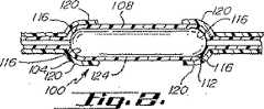
図2に示されているような本発明の一実施形態において、概して符号100で示されている医療用バルーン構造体は、基端コーン部分104と、本体部分108と、先端コーン部分112とを有している。基端コーン部分104および先端コーン部分108はそれぞれ2つの材料層で形成されている。各コーン部分は、内壁116と外壁120とを有する。本体部分112は、単一の材料層124からなる。
【0020】
基端コーン部分と先端コーン部分は付加的な層を備えてもよく、基端コーンと先端コーンの層数が本体部分の層数より多いならば、本体部分も付加的な層を備えてもよい。
【0021】
さらに別の実施形態において、本発明は、基端コーン部分、先端コーン部分および本体部分を含む医療用バルーン構造体に関する。基端コーン部分、先端コーン部分および本体部分はそれぞれ多数の材料層を有する。本体部分の少なくとも一部は、基端コーンおよび先端コーンの少なくとも一方より少数の材料層を有する。基端コーン部分と先端コーン部分の層数は同じであっても異なっていてもよい。基端コーン部分と先端コーン部分が異なる層数を有する場合、層数の差異は、基端コーン部分および先端コーン部分の少なくとも一方から材料層を除去することにより生じ得る。そのようなバルーンの1つは、基端コーン部分の材料層の数を少なくして、バルーンの追従性(trackability)を改良する。
【0022】
本発明のバルーンは多様な目的に使用され得る。本発明のバルーンは、ステントデリバリーカテーテルにおける拡張手段として特に有用である。ステントデリバリー用の医療用バルーン構造体が図4に示されている。カテーテル132の先端部に、図2に示されているものと類似の医療用バルーン構造体100が取付けられている。図示されてはいないが、カテーテル132は、医療用バルーン100と流体が通ずるように連通している膨脹管腔を備えている。医療用バルーン構造体100の本体部分112の周囲にステント128が配置されている。図4に示されているように、望ましくは、基端コーン部分104および先端コーン部分108の外壁120が互いに向かって引き寄せられて、ステント128の基端部と先端部の一部を被覆してステントの保持を支援する。
【0023】
バルーン構造体が複数のチューブで形成されている場合、ステントが滞留し得る凹部を形成するのに十分な数の層を本体部分から除去することが望ましい。
より一般的には、ステント拡張用バルーンの場合、本発明のバルーンの形成に用いられる材料層の数には係わりなく、ステントが滞留し得る凹部を形成するのに十分な材料を除去すべきである。凹部に隣接するバルーン部分が該凹部上に配置される(未拡張の)ステントの高さの少なくとも50%、より望ましくは75%に達するのに十分なバルーン材料を除去することが望ましい。凹部に隣接するバルーン部分が、凹部に配置される(未拡張の)ステントより高くなるほど十分なバルーン材料を除去することがさらに望ましい。そのために、本発明のバルーンは、ステントの本体部分から所定の量の材料を除去することによって製造され得、除去される材料の量は、そのようにして形成された凹部に配置される未拡張ステントの内径および外径に基づいて決定される。
【0024】
さらに、ステント拡張用バルーンの場合、バルーンの本体部分から材料を除去して形成される凹部の軸線方向長さは、凹部に配置されるステントの長さと同じか、それよりわずかに長くすべきである。
【0025】
本発明はさらに、本明細書に開示されている本発明のバルーンを含むカテーテルに関する。一実施形態において、本発明は、本発明のバルーンが配置され、このバルーンの周囲にステントが配置されているステントデリバリーカテーテルに関する。ステントの滞留を支援するために、図4に示されているように、ステントの基端部と先端部とが、その上に引っ張り上げられた基端コーンの一部および先端コーンの一部を有することが望ましい。本発明のバルーンは、ステント拡張用バルーンに合わせて設計された実質的にすべてのステントデリバリーカテーテルと共に用いられ得る。
【0026】
別の態様において、本発明は、体腔内にステントを導入し、その後解放するのに適当なようにステントをカテーテルに固定する方法に関する。この方法は、(a)先端部に上記に開示したような本発明の医療用バルーン構造体が配置されているカテーテルを準備する工程と、(b)収縮および拡張状態を有するステントを準備する工程と、(c)医療用バルーン構造体の本体部分の周囲にステントを配置する工程と、(d)ステントおよび医療用バルーン構造体が収縮状態または状態にあるときに、基端コーンがステントの基端部を覆って配置され、先端コーンがステントの先端部を覆って配置され、それによってステントがカテーテルに固定されるように、基端コーンと先端コーンの一部を互いに向かって引き寄せる工程とを含む。
【0027】
本発明のさらに別の態様において、本発明は、ステントを体腔内に配置する方法に関し、この方法は、(a)上述のように、本発明の医療用バルーン構造体およびステントが固定されているステントデリバリーシステムを準備する工程と、(b)前記ステントデリバリーシステムを体腔内に導入する工程と、(c)医療用バルーン構造体を膨脹させ、それによって同時にステントを拡張させて、ステントの基端部および先端部の上に重なっているコーン部分を、少なくとも部分的にカテーテルを緊縮しているステント上に重なる位置から解放する工程と、(d)カテーテルを体腔から軸線方向に引っ張ってカテーテルを体腔から抜出する工程とを含む。
【0028】
本発明の実施に用いられる医療用バルーンおよびチューブは、ノンコンプライアントバルーン材料、セミコンプライアントバルーン材料およびそれらの組合わせの内から選択された材料で形成することが望ましい。適当なノンコンプライアント材料およびセミコンプライアント材料としては、ポリエチレンテレフタレート(PET)、高密度ポリエチレン、ポリアミド類、ポリカーボネート類、ナイロン、ポリウレタン類、ポリ塩化ビニル、エチレン−酢酸ビニルコポリマーならびにそれらの混合物および組合わせが挙げられる。他の適当な材料には、熱可塑性エラストマー、すなわち、ブロックコポリマー;エチレンのコポリマーおよびターポリマー;プロピレンのホモポリマー、コポリマーおよびターポリマー;エチレンα−オレフィン;ポリエステル;ビニルコポリマー;イオノマー材料などがある。より特定的に言えば、本発明には、Selar(登録商標)、ポリエーテル−ポリエステルブロックコポリマー(デュポン(DuPont)のHytrel(登録商標)、もしくはオランダ、DSMのArnitel(登録商標))、Pebax(登録商標)(ポリエーテルブロックアミドコポリマー)、Surlyn(登録商標)、ポリテトラフルオロエチレン、ポリエーテルウレタン類、ポリエステルウレタン類、ポリウレタン尿素類、ポリウレタンシロキサンブロックコポリマー、シリコーンポリカーボネートコポリマー、アクロリニトリル−ブタジエン−スチレンコポリマー;ポリフェニレンスルフィド類;コポリエステル類もしくは他の類似の押出可能な熱可塑性ポリマー材料、またはそれらの複合材料が用いられ得る。
【0029】
本発明の医療用バルーン構造体は軟質な外層を有することが望ましい。また、本発明の医療用バルーンまたは医療用バルーンチューブはチューブ材料より硬質の材料で製造することが望ましい。こうした目的で、本発明の医療用バルーン構造体を形成するために、医療用バルーンまたは医療用バルーンチューブを、軟質かつ低ジュロメーター硬度の熱可塑性エラストマーチューブ内に挿入してもよい。
【0030】
上記開示は、例示を意図したものであり、全てを網羅するものではない。上記説明は、当業者に多くの変形形態および代替形態を示唆するであろう。これらの代替形態および変形形態はすべて特許請求の範囲内に含まれ、特許請求の範囲において、用語「含んでなる」とは、「〜を含むが、〜に限定されるものではない」ことを意味する。当業者には、本明細書に記載の特定の実施形態に対する他の均等形態が認識されるであろうが、これらの均等形態も特許請求の範囲内に包含されるものとする。
【0031】
以下の特許請求の範囲に記載されている特定の実施形態に加えて、本発明はさらに、以下の特許請求の範囲に記載されている従属的特徴の他の任意の可能な組合わせを有する他の実施形態にも関する。従属請求項に陳述されている特定の特徴は、本発明が特に従属請求項の特徴の任意の他の可能な組合わせを有する他の実施形態にも関するものとみなされるように、本発明の範囲内で他の方式で互いに組合わせられ得る。例えば、請求項を公開するために、後続のいずれの従属請求項も、多数従属形式が管轄区域内で許容された形式である場合には、そのような従属請求項に引用されたすべての先行的限定を有するすべての先行請求項からの多数従属形式で代替的に記載されたものと見なされるべきである(例えば、請求項1に直接従属する各請求項は、これに代わってすべての先行請求項に従属するものとみなされるべきである)。多数従属請求項形式が制限されている管轄区域においては、後続する従属請求項もそれぞれ、以下のそのような従属請求項に列挙されている特定請求項以外の前項の先行的限定を有する請求項からの従属関係をもたらす各単独従属請求項形式で択一的に記載されたものとみなされるべきである(例えば、請求項3は、択一的に請求項2に従属するものとみなされ、請求項4は択一的に請求項2または請求項3に従属するものとみなされ、請求項6は択一的に請求項5に従属するものとみなされ得る)。
【0032】
上記開示は、例示を意図としており、包括的なものではない。上記説明は当業者に多くの変形形態および代替形態を示唆するであろう。これらの代替形態および変形形態はすべて添付特許請求項の範囲内に包含されるものとする。当業者には、本明細書に記載されている特定の実施形態に対する他の均等形態が認識されるであろうが、これらの均等形態も添付特許請求の範囲内に包含されるものとする。
【0033】
2000年2月22日に出願された米国特許出願第09/510,033号はその全文が本明細書に文献援用される。
【図面の簡単な説明】
【図1】 本体部分から材料を除去する前の医療用バルーン構造体の側面図。
【図2】 本体部分から材料を除去した後の図1の医療用バルーン構造体の側面図。
【図3】 図2に示されている医療用バルーン構造体の斜視図。
【図4】 ステントデリバリーカテーテル上に取り付けられ、周囲にステントが配置されている本発明の医療用バルーン構造体の一部の側面図。[0001]
(Background of the Invention)
In normal PTCA surgery, a guide catheter is introduced percutaneously into the cardiovascular system via a blood vessel, and is advanced in the cardiovascular system until the distal end of the catheter reaches a desired position in the vasculature. A guide wire and a dilatation catheter having a balloon at the distal end are introduced through the guide catheter, and the guide wire is slid through the dilatation catheter. First, the guide wire is advanced from the guide catheter into the patient's coronary vasculature and over the previously advanced guide wire until the dilatation balloon is positioned in the proper position beyond the lesion. Proceed. Once in place over the lesion, the flexible inflatable preformed balloon is inflated to a predetermined size using a relatively high liquid or gas at a pressure, for example, greater than about 4 atmospheres. The arteriosclerotic plaque of the lesion is pushed radially inside the arterial wall, thereby dilating the arterial lumen. The balloon is then collapsed into a small shape so that the dilatation catheter can be removed from the patient's vasculature and blood flow is resumed through the dilated artery.
[0002]
In the above types of angioplasty, arterial restenosis can occur, which requires another angioplasty, surgical bypass surgery, or some method of repairing or strengthening the restenosis area. To help prevent restenosis and strengthen the area, the physician can implant an endovascular prosthesis to maintain vascular patency within the diseased artery. Intravascular prostheses or stents are often expanded to larger diameters by the balloon portion of the catheter for placement within the vasculature. Examples of balloon expandable stents are provided in US Pat. No. 5,807,404 and US Pat. No. 5,868,781. The stent is delivered on a stent delivery catheter. Examples of stent delivery catheters include those disclosed in US Pat. No. 5,944,726, US Pat. No. 5,772,669 and US Pat. No. 4,733,665.
[0003]
While carrying the balloon expandable stent to the desired body location, the stent moves relative to the balloon, resulting in a non-uniform expansion of the stent, making it difficult to accurately expand and deploy the stent. There is. Therefore, when delivering a balloon expandable stent to a desired body location, it is desirable to secure the stent to the balloon before expanding the balloon and stent. Many stenting methods and devices have been proposed. U.S. Pat. No. 5,944,726 discloses several stent anchoring devices including a mounting body. U.S. Pat. No. 4,950,227 discloses the use of a sleeve that is arranged to cover the proximal and distal portions of the stent.
[0004]
For purposes of disclosing the present invention, all US patents and patent applications and all other publications cited herein are hereby incorporated by reference in their entirety.
The invention is summarized below but is not intended to limit the scope of the invention in any way.
[0005]
(Summary of Invention)
In one embodiment, the present invention relates to a method of forming a medical balloon structure. According to the method of the present invention, a tube is prepared, and an internal structure selected from among a medical balloon and a medical balloon tube is prepared. Place the tube around the internal structure. The tube and internal structure are then placed in a balloon mold and predetermined pressure, tension and temperature are applied to the tube and internal structure to form a medical balloon structure. The medical balloon structure thus formed includes a proximal cone portion, a main body portion, and a distal end portion, and has an outer wall formed from a tube and an inner wall formed from an internal structure. At least a portion of the outer wall is removed from the body portion of the medical balloon structure. Desirably, the entire outer wall of the body portion area is removed.
One embodiment of the present invention is a method of forming a medical balloon structure, comprising: preparing an internal structure in the form of a medical balloon or medical balloon tube; and preparing at least one tube A step of disposing the at least one tube around the internal structure, a step of placing the internal structure and the tube disposed therearound into a balloon mold, and a predetermined pressure and tension on the tube and the internal structure. And applying a temperature to form a medical balloon structure; the medical balloon structure including a proximal cone portion, a body portion and a distal cone portion; and the medical balloon structure is said at least one An outer wall formed from a tube and an inner wall formed from the internal structure, and the medical balloon structure is a balloon type It provides a process retrieving al, the method comprising the step of removing at least a portion of the outer wall from the body portion of the medical balloon structure.
One embodiment of the present invention includes an outer wall formed from a tube and an inner wall formed from the inner structure formed by applying predetermined pressure, tension, and temperature to the inner structure and a tube disposed around the inner structure. A medical balloon structure having a proximal cone portion, a distal cone portion, and a body portion, wherein the proximal cone portion has at least two material layers, and the distal cone portion includes a plurality of distal cone portions. has a material layer having a body portion a number of material layers,at least a portion of the body portion,the outer wall is removed, with a small number of the material layer of at least one of the proximal cone and a distal cone, medical A balloon structure is provided.
One embodiment of the present invention is a method of forming a medical balloon structure havinga proximal cone, a distal cone, and a body portionextending therebetween , disposed within and around the internal structure. Forming a medical balloon structure comprising a plurality of layers including the outer wall by applying predetermined pressure, tension and temperature to the tube; and from the body portion of the medical balloon structure to at least the outer wall And a method of removing a portion.
[0006]
Furthermore, the present invention provides a step of preparing an internal structure selected from among a medical balloon and a medical balloon tube, and a plurality of tubes arranged in a layer around the internal structure, and the internal structure and the tube. And a method of forming a medical balloon structure. The internal structure and the plurality of tubes are then molded under a predetermined pressure, tension, and temperature to form a medical balloon structure having a proximal cone portion, a distal cone portion, and a body portion. Following molding, the desired number of tube layers are removed from the body portion of the medical balloon structure.
[0007]
The present invention further relates to a medical balloon formed according to the method of the present invention. In particular, the present invention relates to a medical balloon structure formed of an internal structure selected from among a medical balloon and a medical balloon tube and a single tube disposed around the internal structure. The internal structure and tube are molded to form a medical balloon structure having a proximal cone portion, a distal cone portion and a body portion. At this stage, the tube forms the outer wall of the medical balloon structure, and the inner structure forms the inner wall of the medical balloon structure. A part of the outer wall, preferably the entire outer wall, is removed from the main body portion of the medical balloon structure to form the medical balloon structure of the present invention.
[0008]
Furthermore, the present invention relates to a medical balloon structure formed of an internal structure selected from among a medical balloon and a medical balloon tube and a plurality of tubes arranged in layers around the internal structure. The internal structure and the plurality of tubes are molded to form a medical balloon structure having a proximal cone portion, a distal cone portion, and a body portion. After molding, a desired number of tube layers are removed from the body portion of the medical balloon structure.
[0009]
In yet another embodiment, the present invention relates to a medical balloon structure that includes a proximal cone portion, a distal cone portion, and a body portion. The proximal cone portion, the distal cone portion, and the body portion each have multiple layers of material. At least a portion of the body portion has fewer layers of material than at least one of the proximal cone and the distal cone.
[0010]
The present invention further relates to a catheter comprising the medical balloon of the present invention. One such catheter is a stent delivery catheter that utilizes the balloon of the present invention. Desirably, at least one outer layer of the proximal cone portion and the distal cone portion is moved toward each other to stay on the proximal and distal portions of the stent.
[0011]
In another aspect, the invention relates to a method of securing a stent to a catheter so that the stent is suitable for introduction into a body cavity and subsequent release. This method includes (a) preparing a catheter in which the medical balloon structure of the present invention as described above is disposed around the tip, and (b) preparing a stent having a contraction and expansion state. And (c) a step of placing the stent around the body portion of the medical balloon structure; and (d) a portion of the proximal cone covering the proximal end of the stent, and a portion of the distal cone A portion of the proximal cone and the distal cone so that the stent is secured to the catheter when the stent and the medical balloon structure are in a deflated state or state. And drawing a part of them toward each other.
[0012]
In yet another aspect of the present invention, the present invention relates to a method for placing a stent in a body cavity, the method comprising: (a) providing a medical balloon structure of the present invention and a stent delivery system to which the stent is fixed. (B) introducing the stent delivery system into the body cavity; (c) inflating the medical balloon structure, thereby simultaneously expanding the stent, and the proximal end of the stent at both cone portions. And releasing the portion overlying the tip from a position overlying the stent that at least partially contracts the catheter; and (d) pulling the catheter axially from the body cavity and withdrawing the catheter from the body cavity. Including.
[0013]
(Detailed description of the invention)
While this invention may be embodied in many different forms, there are described in detail herein specific preferred embodiments of the invention. This description is an exemplification of the principles of the invention and is not intended to limit the invention to the particular embodiments illustrated.
[0014]
For purposes of the present disclosure, the term stent refers to stents, stent grafts, grafts and other luminal prostheses.
In one embodiment, the present invention relates to a method of forming the medical balloon structure of the present invention. According to this method, an internal structure in the form of a medical balloon is prepared and a tube is prepared. A tube is placed around the balloon and the tube and medical balloon are placed in a balloon mold. Predetermined pressure, tension and temperature are applied to the tube and balloon in the balloon mold according to well-known balloon manufacturing methods to form a medical balloon structure. The resulting medical balloon structure is indicated generally at 100 in FIG. 1 and has a
[0015]
In another embodiment of the present invention, an internal structure in the form of a medical balloon tube and a second tube are provided. A second tube is placed around the balloon tube and the second tube and the medical balloon tube are placed in a balloon mold. In order to form a medical balloon structure, predetermined pressure, tension and temperature are applied to the second tube and balloon tube in the balloon mold in accordance with known balloon manufacturing methods. After molding, a desired amount of balloon material is removed from the body portion of the medical balloon structure.
[0016]
Furthermore, the present invention provides a step of preparing a medical balloon or medical balloon tube, a plurality of tubes arranged in a layer around the medical balloon or medical balloon tube, a balloon (or balloon tube), and a plurality of tubes And a method of forming a medical balloon structure. Thereafter, a medical balloon (or balloon tube) and a plurality of tubes are formed under a predetermined pressure, tension and temperature so as to form a medical balloon structure having a proximal cone portion, a distal cone portion and a body portion. To do. After molding, a desired number of tube layers are removed from the body portion of the medical balloon structure.
[0017]
The material removal step can be accomplished using any of a number of material removal techniques including mechanical techniques, chemical techniques or lasers. The mechanical outer layer removing means includes mechanical trimming, cutting and polishing. A suitable polishing method is described in US patent application Ser. No. 09 / 401,618, filed Sep. 22, 1999 and assigned to the assignee of the present invention. The outer layer may mask the appropriate portion of the balloon and chemically etch the balloon, or the layer may be removed from the body portion by laser ablation. A suitable laser ablation method is disclosed in US Pat. No. 5,826,588 to Forman.
[0018]
The present invention further relates to a balloon of the present invention formed according to the method of the present invention disclosed herein.
The present invention further relates to a medical balloon structure in which a main body portion and a cone portion are made of a predetermined number of material layers. The number of material layers in the cone portion is different from the number of material layers in the body portion. The number of material layers in the cone portion of the balloon structure is preferably greater than the number of material layers in the body portion.
[0019]
In one embodiment of the present invention as shown in FIG. 2, a medical balloon structure, generally designated 100, includes a
[0020]
The proximal cone portion and the distal cone portion may have additional layers, and if the number of layers of the proximal cone and distal cone is greater than the number of layers in the body portion, the body portion may also have additional layers. Good.
[0021]
In yet another embodiment, the present invention relates to a medical balloon structure that includes a proximal cone portion, a distal cone portion, and a body portion. The proximal cone portion, the distal cone portion, and the body portion each have multiple layers of material. At least a portion of the body portion has fewer layers of material than at least one of the proximal cone and the distal cone. The number of layers of the proximal cone portion and the distal cone portion may be the same or different. When the proximal cone portion and the distal cone portion have different numbers of layers, the difference in the number of layers can be caused by removing the material layer from at least one of the proximal cone portion and the distal cone portion. One such balloon improves the trackability of the balloon by reducing the number of material layers in the proximal cone portion.
[0022]
The balloon of the present invention can be used for various purposes. The balloon of the present invention is particularly useful as an expansion means in a stent delivery catheter. A medical balloon structure for stent delivery is shown in FIG. A
[0023]
If the balloon structure is formed of multiple tubes, it is desirable to remove a sufficient number of layers from the body portion to form a recess where the stent can stay.
More generally, in the case of a stent-expanding balloon, regardless of the number of material layers used to form the balloon of the present invention, enough material should be removed to form a recess in which the stent can stay. is there. It is desirable to remove enough balloon material so that the balloon portion adjacent to the recess reaches at least 50%, more desirably 75% of the height of the (unexpanded) stent placed over the recess. It is further desirable to remove enough balloon material such that the balloon portion adjacent to the recess is higher than the (unexpanded) stent placed in the recess. To that end, the balloon of the present invention can be manufactured by removing a predetermined amount of material from the main body portion of the stent, the amount of material removed being unexpanded placed in the recess so formed. It is determined based on the inner diameter and outer diameter of the stent.
[0024]
Furthermore, in the case of a stent expansion balloon, the axial length of the recess formed by removing material from the balloon body should be the same as or slightly longer than the length of the stent placed in the recess. is there.
[0025]
The present invention further relates to a catheter comprising the balloon of the present invention as disclosed herein. In one embodiment, the present invention relates to a stent delivery catheter in which a balloon of the present invention is disposed and a stent is disposed around the balloon. In order to assist in the retention of the stent, as shown in FIG. 4, the proximal and distal ends of the stent have a portion of the proximal cone and a portion of the distal cone pulled up thereon. It is desirable to have. The balloon of the present invention may be used with virtually any stent delivery catheter designed for a stent expansion balloon.
[0026]
In another aspect, the present invention relates to a method of securing a stent to a catheter as appropriate for introducing and subsequently releasing the stent into a body cavity. This method includes the steps of (a) preparing a catheter in which the medical balloon structure of the present invention as disclosed above is disposed at the distal end, and (b) preparing a stent having a contracted and expanded state. (C) placing the stent around the body portion of the medical balloon structure; and (d) when the stent and the medical balloon structure are in a deflated state, the proximal cone is the base of the stent. Pulling the proximal cone and a portion of the distal cone toward each other so that the distal cone is disposed over the distal end of the stent, thereby securing the stent to the catheter. Including.
[0027]
In yet another aspect of the present invention, the present invention relates to a method for placing a stent in a body cavity, wherein (a) the medical balloon structure of the present invention and the stent are fixed as described above. Providing a stent delivery system; (b) introducing the stent delivery system into a body cavity; and (c) inflating the medical balloon structure, thereby simultaneously expanding the stent, Releasing the cone portion overlying the head portion and the tip portion from a position overlying the stent at least partially constricting the catheter; and (d) pulling the catheter axially from the body cavity to remove the catheter from the body cavity. And a step of extracting from.
[0028]
The medical balloons and tubes used in the practice of the present invention are preferably formed of a material selected from non-compliant balloon materials, semi-compliant balloon materials, and combinations thereof. Suitable non-compliant and semi-compliant materials include polyethylene terephthalate (PET), high density polyethylene, polyamides, polycarbonates, nylon, polyurethanes, polyvinyl chloride, ethylene-vinyl acetate copolymers and mixtures and combinations thereof. Is mentioned. Other suitable materials include thermoplastic elastomers, i.e. block copolymers; copolymers and terpolymers of ethylene; homopolymers, copolymers and terpolymers of propylene; ethylene alpha-olefins; polyesters; vinyl copolymers; More specifically, the invention includes Selar®, a polyether-polyester block copolymer (DuPont's Hytrel®, or DSM, Arnitel®), Pebax ( (Registered trademark) (polyether block amide copolymer), Surlyn (registered trademark), polytetrafluoroethylene, polyether urethanes, polyester urethanes, polyurethane ureas, polyurethane siloxane block copolymers, silicone polycarbonate copolymers, acrylonitrile-butadiene-styrene Copolymers; polyphenylene sulfides; copolyesters or other similar extrudable thermoplastic polymer materials, or composites thereof may be used.
[0029]
The medical balloon structure of the present invention desirably has a soft outer layer. The medical balloon or medical balloon tube of the present invention is preferably manufactured from a material harder than the tube material. For these purposes, a medical balloon or medical balloon tube may be inserted into a soft and low durometer thermoplastic elastomer tube to form the medical balloon structure of the present invention.
[0030]
The above disclosure is intended to be illustrative and not exhaustive. The above description will suggest many variations and alternatives to one of ordinary skill in this art. All these alternatives and variations are included within the scope of the claims, and in the claims, the term “comprising” means “including, but not limited to”. means. Those skilled in the art will recognize other equivalent forms for the specific embodiments described herein, which equivalents are intended to be encompassed within the scope of the claims.
[0031]
In addition to the specific embodiments described in the following claims, the present invention further includes any other possible combinations of the dependent features described in the following claims. This embodiment also relates to this embodiment. The particular features stated in the dependent claims are such that the present invention is considered to also relate to other embodiments which have any other possible combinations of features of the dependent claims. It can be combined with each other in other ways within the scope. For example, to publish a claim, any subsequent dependent claim shall have all preceding claims cited in such dependent claim if the multiple dependent form is an allowed form within the jurisdiction. Should be regarded as being alternatively stated in multiple subordinate forms from all preceding claims with specific limitations (eg, each claim directly dependent on
[0032]
The above disclosure is intended to be illustrative and not exhaustive. The above description will suggest many variations and alternatives to one of ordinary skill in this art. All these alternatives and variations are intended to be included within the scope of the appended claims. Those skilled in the art will recognize other equivalent forms for the specific embodiments described herein, which are intended to be included within the scope of the appended claims.
[0033]
US patent application Ser. No. 09 / 510,033 filed Feb. 22, 2000 is hereby incorporated by reference in its entirety.
[Brief description of the drawings]
FIG. 1 is a side view of a medical balloon structure before material is removed from a body portion.
2 is a side view of the medical balloon structure of FIG. 1 after removing material from the body portion.
3 is a perspective view of the medical balloon structure shown in FIG. 2. FIG.
FIG. 4 is a side view of a portion of the medical balloon structure of the present invention mounted on a stent delivery catheter and having a stent disposed around it.
Claims (32)
Translated fromJapanese医療用バルーンまたは医療用バルーンチューブの形態をとる内部構成体を準備する工程と、
少なくとも1つのチューブを準備する工程と、
内部構成体の周囲に前記少なくとも1つのチューブを配置する工程と、
内部構成体およびその周囲に配置された前記少なくとも1つのチューブをバルーン型に入れる工程と、
チューブおよび内部構成体に、所定の圧力、張力および温度を加えて医療用バルーン構造体を形成する工程と、該医療用バルーン構造体が基端コーン部分、本体部分および先端コーン部分を含むことと、該医療用バルーン構造体が前記少なくとも1つのチューブから形成された外壁と前記内部構成体から形成された内壁とを有することと、
前記医療用バルーン構造体をバルーン型から取り出す工程と、
前記医療用バルーン構造体の本体部分から外壁の少なくとも一部を除去する工程とを含んでなる方法。A method for forming a medical balloon structure, comprising:
Providing an internal component in the form of a medical balloon or medical balloon tube;
Providing at least one tube;
Placing the at least one tube around an internal structure;
Placing the internal structure and the at least one tube disposed around it into a balloon mold;
Applying a predetermined pressure, tension and temperature to the tube and the internal structure to form a medical balloon structure; the medical balloon structure including a proximal cone portion, a body portion and a distal cone portion; The medical balloon structure has an outer wall formed from the at least one tube and an inner wall formed from the inner structure;
Removing the medical balloon structure from a balloon mold;
Removing at least a portion of the outer wall from the body portion of the medical balloon structure.
ノンコンプライアントバルーン材料、セミコンプライアントバルーン材料およびそれらの組合わせの内から選択された材料で前記内部構成体を形成し、
熱可塑性エラストマーで前記少なくとも1つのチューブを形成し、かつ、
該チューブの材料より硬質の材料で前記内部構成体を形成する請求項1に記載の方法。Remove the entire outer wall from the body part of the balloon structure,
Forming the internal structure with a material selected from non-compliant balloon materials, semi-compliant balloon materials and combinations thereof;
Forming the at least one tube with a thermoplastic elastomer; and
The method of claim 1, wherein the internal structure is formed of a material that is harder than the material of the tube.
基端コーン部分と、
先端コーン部分と、
本体部分とを含んでなり、
基端コーン部分が少なくとも2つの材料層を有し、
先端コーン部分が多数の材料層を有し、
本体部分が多数の材料層を有し、
本体部分の少なくとも一部は、外壁が除去されて、基端コーンおよび先端コーンの少なくとも一方より少数の材料層を有する医療用バルーン構造体。A medical balloon structure having an outer wall formed from a tube and an inner wall formed from an inner structure formed by applying predetermined pressure, tension, and temperature to the inner structure and a tube disposed around the inner structure. There,
A proximal cone portion;
The tip cone part,
A main body part,
The proximal cone portion has at least two layers of material;
The tip cone part has a large number of material layers,
The body part has a number of material layers,
At least a partof the main body part is a medical balloon structure having anouter wall removed and having a material layer fewer than at least one of a proximal cone and a distal cone.
外壁は単一のチューブで形成されている、請求項17に記載の医療用バルーン構造体。The inner wall is formed of a selected internal structure that takes the form of a medical balloon or medical balloon tube;
The outer wall RuTei is formed of a single tube, a medical balloon structure according to claim 17.
内部構成体が、コンプライアントバルーン材料、セミコンプライアントバルーン材料およびそれらの組合わせの内から選択された材料で形成され、
外壁を形成するチューブが熱可塑性エラストマーで形成されている請求項17に記載の医療用バルーン構造体。The outer wall of the proximal cone and the outer wall of the distal cone are formed of a softer material than the material forming the internal structure,
The internal structure is formed of a material selected from a compliant balloon material, a semi-compliant balloon material, and combinations thereof;
The medical balloon structure according to claim 17, wherein the tube forming the outer wall is formed of a thermoplastic elastomer.
内部構成体およびその周囲に配置されたチューブに対して所定の圧力、張力および温度を加えることにより、外壁を含めた複数の層を含んでなる医療用バルーン構造体を形成する工程と、
医療用バルーン構造体の本体部分から外壁の少なくとも一部を除去する工程とを含んでなる方法。A method of forming a medical balloon structure havinga proximal cone, a distal cone, and a body portionextending therebetween,
Forming a medical balloon structure comprising a plurality of layers including an outer wall by applying predetermined pressure, tension and temperature to the internal structure and the tube disposed therearound; and
Removing at least a portion of the outer wall from the body portion of the medical balloon structure.
Applications Claiming Priority (3)
| Application Number | Priority Date | Filing Date | Title |
|---|---|---|---|
| US09/510,033US6562061B1 (en) | 2000-02-22 | 2000-02-22 | Stent delivery balloon with securement structure |
| US09/510,033 | 2000-02-22 | ||
| PCT/US2001/002010WO2001062327A1 (en) | 2000-02-22 | 2001-01-22 | Stent delivery balloon with stent securement means |
Publications (2)
| Publication Number | Publication Date |
|---|---|
| JP2003523268A JP2003523268A (en) | 2003-08-05 |
| JP4829456B2true JP4829456B2 (en) | 2011-12-07 |
Family
ID=24029084
Family Applications (1)
| Application Number | Title | Priority Date | Filing Date |
|---|---|---|---|
| JP2001561386AExpired - Fee RelatedJP4829456B2 (en) | 2000-02-22 | 2001-01-22 | Stent delivery balloon having stent fixing means |
Country Status (8)
| Country | Link |
|---|---|
| US (1) | US6562061B1 (en) |
| EP (1) | EP1259280B1 (en) |
| JP (1) | JP4829456B2 (en) |
| AT (1) | ATE376438T1 (en) |
| CA (1) | CA2400284A1 (en) |
| DE (1) | DE60131068T2 (en) |
| ES (1) | ES2296729T3 (en) |
| WO (1) | WO2001062327A1 (en) |
Families Citing this family (16)
| Publication number | Priority date | Publication date | Assignee | Title |
|---|---|---|---|---|
| DE10244847A1 (en) | 2002-09-20 | 2004-04-01 | Ulrich Prof. Dr. Speck | Medical device for drug delivery |
| US7758630B2 (en) | 2003-04-14 | 2010-07-20 | Tryton Medical, Inc. | Helical ostium support for treating vascular bifurcations |
| US7731747B2 (en)* | 2003-04-14 | 2010-06-08 | Tryton Medical, Inc. | Vascular bifurcation prosthesis with multiple thin fronds |
| US7717953B2 (en) | 2004-10-13 | 2010-05-18 | Tryton Medical, Inc. | Delivery system for placement of prosthesis at luminal OS |
| US7481834B2 (en) | 2003-04-14 | 2009-01-27 | Tryton Medical, Inc. | Stent for placement at luminal os |
| US7972372B2 (en)* | 2003-04-14 | 2011-07-05 | Tryton Medical, Inc. | Kit for treating vascular bifurcations |
| US8083791B2 (en) | 2003-04-14 | 2011-12-27 | Tryton Medical, Inc. | Method of treating a lumenal bifurcation |
| US8109987B2 (en)* | 2003-04-14 | 2012-02-07 | Tryton Medical, Inc. | Method of treating a lumenal bifurcation |
| US8512388B1 (en) | 2004-06-24 | 2013-08-20 | Advanced Cardiovascular Systems, Inc. | Stent delivery catheter with improved stent retention and method of making same |
| US20070288081A1 (en)* | 2006-05-18 | 2007-12-13 | Abbott Laboratories | Stent delivery system having a stent stopper |
| EP2410926A4 (en) | 2009-03-25 | 2012-12-05 | Svelte Medical Systems Inc | BALLOON EQUIPMENT AND METHOD FOR THE PRODUCTION AND USE THEREOF |
| US8382818B2 (en) | 2009-07-02 | 2013-02-26 | Tryton Medical, Inc. | Ostium support for treating vascular bifurcations |
| EP2642946B1 (en) | 2010-11-24 | 2023-08-16 | Poseidon Medical Inc. | Support for treating vascular bifurcations |
| US10500077B2 (en) | 2012-04-26 | 2019-12-10 | Poseidon Medical Inc. | Support for treating vascular bifurcations |
| CA3075636A1 (en) | 2017-10-04 | 2019-04-11 | Zorion Medical, Inc. | Delivery balloon with retractable retention cuffs |
| WO2022115445A1 (en)* | 2020-11-25 | 2022-06-02 | Jihad Ali Mustapha | Peripheral artery balloonn, a hypo-tube for preparing a peripheral artery balloon and methods of use thereof |
Citations (2)
| Publication number | Priority date | Publication date | Assignee | Title |
|---|---|---|---|---|
| JPH0464367A (en)* | 1990-07-03 | 1992-02-28 | Olympus Optical Co Ltd | Expander for vital duct |
| US5409495A (en)* | 1993-08-24 | 1995-04-25 | Advanced Cardiovascular Systems, Inc. | Apparatus for uniformly implanting a stent |
Family Cites Families (25)
| Publication number | Priority date | Publication date | Assignee | Title |
|---|---|---|---|---|
| US4733665C2 (en) | 1985-11-07 | 2002-01-29 | Expandable Grafts Partnership | Expandable intraluminal graft and method and apparatus for implanting an expandable intraluminal graft |
| US4950227A (en) | 1988-11-07 | 1990-08-21 | Boston Scientific Corporation | Stent delivery system |
| US6004289A (en) | 1990-05-15 | 1999-12-21 | Medtronic Ave, Inc. | Multiple layer high strength balloon for dilatation catheter |
| US5403341A (en) | 1994-01-24 | 1995-04-04 | Solar; Ronald J. | Parallel flow endovascular stent and deployment apparatus therefore |
| US5470313A (en) | 1994-02-24 | 1995-11-28 | Cardiovascular Dynamics, Inc. | Variable diameter balloon dilatation catheter |
| US5836965A (en) | 1994-10-19 | 1998-11-17 | Jendersee; Brad | Stent delivery and deployment method |
| US5632760A (en) | 1994-10-20 | 1997-05-27 | Cordis Corporation | Balloon catheter for stent implantation |
| NL9500283A (en) | 1994-10-21 | 1996-06-03 | Cordis Europ | Catheter with guide wire channel. |
| DE19540084A1 (en) | 1995-10-27 | 1997-04-30 | Figulla Hans Reiner Prof Dr Me | Device for applying a stent |
| US6579305B1 (en) | 1995-12-07 | 2003-06-17 | Medtronic Ave, Inc. | Method and apparatus for delivery deployment and retrieval of a stent comprising shape-memory material |
| US5807327A (en) | 1995-12-08 | 1998-09-15 | Ethicon, Inc. | Catheter assembly |
| US5733301A (en) | 1996-01-11 | 1998-03-31 | Schneider (Usa) Inc. | Laser ablation of angioplasty catheters and balloons |
| US6124007A (en) | 1996-03-06 | 2000-09-26 | Scimed Life Systems Inc | Laminate catheter balloons with additive burst strength and methods for preparation of same |
| US5980530A (en) | 1996-08-23 | 1999-11-09 | Scimed Life Systems Inc | Stent delivery system |
| JP3968444B2 (en) | 1996-08-23 | 2007-08-29 | ボストン サイエンティフィック サイムド,インコーポレイテッド | Stent delivery mechanism with stent fixation device |
| US5944726A (en) | 1996-08-23 | 1999-08-31 | Scimed Life Systems, Inc. | Stent delivery system having stent securement means |
| US6395008B1 (en)* | 1996-08-23 | 2002-05-28 | Scimed Life Systems, Inc. | Stent delivery device using stent cups and mounting collars |
| US5807404A (en) | 1996-09-19 | 1998-09-15 | Medinol Ltd. | Stent with variable features to optimize support and method of making such stent |
| US5913871A (en) | 1996-09-25 | 1999-06-22 | Medtronic, Inc. | Balloon modification for improved stent fixation and deployment |
| US5772669A (en) | 1996-09-27 | 1998-06-30 | Scimed Life Systems, Inc. | Stent deployment catheter with retractable sheath |
| US5868781A (en) | 1996-10-22 | 1999-02-09 | Scimed Life Systems, Inc. | Locking stent |
| US5810871A (en) | 1997-04-29 | 1998-09-22 | Medtronic, Inc. | Stent delivery system |
| US5971990A (en) | 1998-04-20 | 1999-10-26 | Invatec S.R.L. | System for introducing and positioning expandable stents |
| US6331186B1 (en)* | 1999-03-22 | 2001-12-18 | Scimed Life Systems, Inc. | End sleeve coating for stent delivery |
| US6221097B1 (en)* | 1999-03-22 | 2001-04-24 | Scimed Life System, Inc. | Lubricated sleeve material for stent delivery |
- 2000
- 2000-02-22USUS09/510,033patent/US6562061B1/ennot_activeExpired - Lifetime
- 2001
- 2001-01-22ATAT01906612Tpatent/ATE376438T1/ennot_activeIP Right Cessation
- 2001-01-22CACA002400284Apatent/CA2400284A1/ennot_activeAbandoned
- 2001-01-22ESES01906612Tpatent/ES2296729T3/ennot_activeExpired - Lifetime
- 2001-01-22EPEP01906612Apatent/EP1259280B1/ennot_activeExpired - Lifetime
- 2001-01-22WOPCT/US2001/002010patent/WO2001062327A1/enactiveIP Right Grant
- 2001-01-22JPJP2001561386Apatent/JP4829456B2/ennot_activeExpired - Fee Related
- 2001-01-22DEDE60131068Tpatent/DE60131068T2/ennot_activeExpired - Lifetime
Patent Citations (2)
| Publication number | Priority date | Publication date | Assignee | Title |
|---|---|---|---|---|
| JPH0464367A (en)* | 1990-07-03 | 1992-02-28 | Olympus Optical Co Ltd | Expander for vital duct |
| US5409495A (en)* | 1993-08-24 | 1995-04-25 | Advanced Cardiovascular Systems, Inc. | Apparatus for uniformly implanting a stent |
Also Published As
| Publication number | Publication date |
|---|---|
| EP1259280A1 (en) | 2002-11-27 |
| DE60131068D1 (en) | 2007-12-06 |
| CA2400284A1 (en) | 2001-08-30 |
| US6562061B1 (en) | 2003-05-13 |
| ATE376438T1 (en) | 2007-11-15 |
| EP1259280B1 (en) | 2007-10-24 |
| WO2001062327A1 (en) | 2001-08-30 |
| JP2003523268A (en) | 2003-08-05 |
| DE60131068T2 (en) | 2008-02-14 |
| ES2296729T3 (en) | 2008-05-01 |
Similar Documents
| Publication | Publication Date | Title |
|---|---|---|
| US5976155A (en) | System for removably securing a stent on a catheter assembly and method of use | |
| US5980530A (en) | Stent delivery system | |
| US6371962B1 (en) | Stent delivery system with stent securement means | |
| US7226472B2 (en) | Catheter balloon with advantageous cone design | |
| US6428568B2 (en) | Catheter balloon with biased multiple wings | |
| JP4829456B2 (en) | Stent delivery balloon having stent fixing means | |
| US6217586B1 (en) | Catheter and method for a stent delivery system | |
| JP4619653B2 (en) | Balloon catheter having an inner tube with a foldable portion | |
| JP3753437B2 (en) | Balloon catheter | |
| US6383212B2 (en) | Balloon catheter and stent deploying catheter system | |
| US6506202B1 (en) | Expandable stent dimensional retention system and method | |
| US8152819B2 (en) | Catheter support for stent delivery | |
| US6527741B1 (en) | Angioplasty catheter system with adjustable balloon length | |
| JP2002520095A (en) | Balloon catheter inflating balloon at distal end of balloon and stent delivery system | |
| JP2005525138A (en) | Stent delivery catheter with grooved balloon and method of manufacturing the same | |
| US7147817B1 (en) | Method of making a low profile balloon | |
| CN115501024A (en) | Device for expanding a stent | |
| WO2001017459A1 (en) | System for removably securing a stent on a catheter assembly and method of use |
Legal Events
| Date | Code | Title | Description |
|---|---|---|---|
| A621 | Written request for application examination | Free format text:JAPANESE INTERMEDIATE CODE: A621 Effective date:20080122 | |
| A131 | Notification of reasons for refusal | Free format text:JAPANESE INTERMEDIATE CODE: A131 Effective date:20100601 | |
| A521 | Request for written amendment filed | Free format text:JAPANESE INTERMEDIATE CODE: A523 Effective date:20100830 | |
| A131 | Notification of reasons for refusal | Free format text:JAPANESE INTERMEDIATE CODE: A131 Effective date:20110222 | |
| A521 | Request for written amendment filed | Free format text:JAPANESE INTERMEDIATE CODE: A523 Effective date:20110325 | |
| TRDD | Decision of grant or rejection written | ||
| A01 | Written decision to grant a patent or to grant a registration (utility model) | Free format text:JAPANESE INTERMEDIATE CODE: A01 Effective date:20110906 | |
| A01 | Written decision to grant a patent or to grant a registration (utility model) | Free format text:JAPANESE INTERMEDIATE CODE: A01 | |
| A61 | First payment of annual fees (during grant procedure) | Free format text:JAPANESE INTERMEDIATE CODE: A61 Effective date:20110916 | |
| FPAY | Renewal fee payment (event date is renewal date of database) | Free format text:PAYMENT UNTIL: 20140922 Year of fee payment:3 | |
| R150 | Certificate of patent or registration of utility model | Ref document number:4829456 Country of ref document:JP Free format text:JAPANESE INTERMEDIATE CODE: R150 Free format text:JAPANESE INTERMEDIATE CODE: R150 | |
| R250 | Receipt of annual fees | Free format text:JAPANESE INTERMEDIATE CODE: R250 | |
| R250 | Receipt of annual fees | Free format text:JAPANESE INTERMEDIATE CODE: R250 | |
| R250 | Receipt of annual fees | Free format text:JAPANESE INTERMEDIATE CODE: R250 | |
| R250 | Receipt of annual fees | Free format text:JAPANESE INTERMEDIATE CODE: R250 | |
| R250 | Receipt of annual fees | Free format text:JAPANESE INTERMEDIATE CODE: R250 | |
| R250 | Receipt of annual fees | Free format text:JAPANESE INTERMEDIATE CODE: R250 | |
| LAPS | Cancellation because of no payment of annual fees |