JP4829049B2 - Wireless communication method and wireless base station - Google Patents
Wireless communication method and wireless base stationDownload PDFInfo
- Publication number
- JP4829049B2 JP4829049B2JP2006233803AJP2006233803AJP4829049B2JP 4829049 B2JP4829049 B2JP 4829049B2JP 2006233803 AJP2006233803 AJP 2006233803AJP 2006233803 AJP2006233803 AJP 2006233803AJP 4829049 B2JP4829049 B2JP 4829049B2
- Authority
- JP
- Japan
- Prior art keywords
- transmission power
- carrier
- power difference
- transmission
- base station
- Prior art date
- Legal status (The legal status is an assumption and is not a legal conclusion. Google has not performed a legal analysis and makes no representation as to the accuracy of the status listed.)
- Expired - Fee Related
Links
Images


Classifications
- H—ELECTRICITY
- H04—ELECTRIC COMMUNICATION TECHNIQUE
- H04W—WIRELESS COMMUNICATION NETWORKS
- H04W52/00—Power management, e.g. Transmission Power Control [TPC] or power classes
- H04W52/04—Transmission power control [TPC]
- H04W52/06—TPC algorithms
- H04W52/16—Deriving transmission power values from another channel
- H—ELECTRICITY
- H04—ELECTRIC COMMUNICATION TECHNIQUE
- H04W—WIRELESS COMMUNICATION NETWORKS
- H04W52/00—Power management, e.g. Transmission Power Control [TPC] or power classes
- H04W52/04—Transmission power control [TPC]
- H04W52/06—TPC algorithms
- H04W52/14—Separate analysis of uplink or downlink
- H04W52/146—Uplink power control
- H—ELECTRICITY
- H04—ELECTRIC COMMUNICATION TECHNIQUE
- H04W—WIRELESS COMMUNICATION NETWORKS
- H04W72/00—Local resource management
- H04W72/50—Allocation or scheduling criteria for wireless resources
- H04W72/54—Allocation or scheduling criteria for wireless resources based on quality criteria
- H—ELECTRICITY
- H04—ELECTRIC COMMUNICATION TECHNIQUE
- H04L—TRANSMISSION OF DIGITAL INFORMATION, e.g. TELEGRAPHIC COMMUNICATION
- H04L27/00—Modulated-carrier systems
- H04L27/26—Systems using multi-frequency codes
- H04L27/2601—Multicarrier modulation systems
- H04L27/2602—Signal structure
- H—ELECTRICITY
- H04—ELECTRIC COMMUNICATION TECHNIQUE
- H04L—TRANSMISSION OF DIGITAL INFORMATION, e.g. TELEGRAPHIC COMMUNICATION
- H04L5/00—Arrangements affording multiple use of the transmission path
- H04L5/0001—Arrangements for dividing the transmission path
- H04L5/0003—Two-dimensional division
- H04L5/0005—Time-frequency
- H04L5/0007—Time-frequency the frequencies being orthogonal, e.g. OFDM(A) or DMT
- H—ELECTRICITY
- H04—ELECTRIC COMMUNICATION TECHNIQUE
- H04W—WIRELESS COMMUNICATION NETWORKS
- H04W52/00—Power management, e.g. Transmission Power Control [TPC] or power classes
- H04W52/04—Transmission power control [TPC]
- H04W52/30—Transmission power control [TPC] using constraints in the total amount of available transmission power
- H04W52/36—Transmission power control [TPC] using constraints in the total amount of available transmission power with a discrete range or set of values, e.g. step size, ramping or offsets
- H04W52/367—Power values between minimum and maximum limits, e.g. dynamic range
- H—ELECTRICITY
- H04—ELECTRIC COMMUNICATION TECHNIQUE
- H04W—WIRELESS COMMUNICATION NETWORKS
- H04W68/00—User notification, e.g. alerting and paging, for incoming communication, change of service or the like
- H—ELECTRICITY
- H04—ELECTRIC COMMUNICATION TECHNIQUE
- H04W—WIRELESS COMMUNICATION NETWORKS
- H04W72/00—Local resource management
- H04W72/04—Wireless resource allocation
- H04W72/044—Wireless resource allocation based on the type of the allocated resource
- H04W72/0446—Resources in time domain, e.g. slots or frames
- H—ELECTRICITY
- H04—ELECTRIC COMMUNICATION TECHNIQUE
- H04W—WIRELESS COMMUNICATION NETWORKS
- H04W72/00—Local resource management
- H04W72/50—Allocation or scheduling criteria for wireless resources
- H04W72/54—Allocation or scheduling criteria for wireless resources based on quality criteria
- H04W72/542—Allocation or scheduling criteria for wireless resources based on quality criteria using measured or perceived quality
Landscapes
- Engineering & Computer Science (AREA)
- Signal Processing (AREA)
- Computer Networks & Wireless Communication (AREA)
- Quality & Reliability (AREA)
- Mobile Radio Communication Systems (AREA)
Description
Translated fromJapanese本発明は、複数のキャリアを用いたマルチキャリアによる上り方向での無線通信方法、及びマルチキャリアによって無線通信端末と接続された無線基地局に関する。 The present invention relates to a radio communication method in the uplink direction by a multicarrier using a plurality of carriers and a radio base station connected to a radio communication terminal by the multicarrier.
近年、動画像やゲームなど、取り扱うアプリケーションの多様化及び高度化に伴って、移動体通信システムにおいてもデータ伝送速度の高速化が強く求められている。このような背景を踏まえ、例えば、3GPP2では、複数のキャリアを上位レイヤで束ねて用いることによって高速なデータ伝送を実現する方法(いわゆるマルチキャリア)が規定されている。 In recent years, with the diversification and sophistication of applications such as moving images and games, there is a strong demand for higher data transmission speeds in mobile communication systems. In view of such a background, for example, 3GPP2 defines a method (so-called multicarrier) for realizing high-speed data transmission by using a plurality of carriers in a bundle in an upper layer.
マルチキャリアの場合、無線通信端末(Access Terminal)では、小型化や製造コスト削減などの観点から、一般的に同一の無線通信回路を用いて複数のキャリアを送信する構成が採用される。そこで、所定の周波数間隔(1.25MHz間隔)を有して隣接する隣接キャリア間の干渉を低減するため、隣接キャリア間の送信電力差を所定の閾値(MaxRLTxPwrDiff、例えば、15dB)以内に抑えることが規定されている(例えば、非特許文献1)。
上述したように、3GPP2では、隣接キャリア間の送信電力差を所定の閾値(MaxRLTxPwrDiff)以内に抑えることが規定されているが、無線通信端末と無線基地局(Access Network)との通信の状態によっては、送信電力差を所定の閾値以内に維持することができない場合がある。 As described above, 3GPP2 stipulates that the transmission power difference between adjacent carriers should be kept within a predetermined threshold (MaxRLTxPwrDiff). May not be able to maintain the transmission power difference within a predetermined threshold.
例えば、無線通信端末が、第1のキャリアを用いて通信を実行している第1の無線基地局から遠ざかるとともに、第1のキャリアから所定の周波数間隔を有して隣接する第2のキャリアを用いて通信を実行している第2の無線基地局に近付いている場合、当該無線通信端末は、第1のキャリアを用いた第1の無線基地局との通信を維持するため、第1のキャリアの送信電力を増大する必要がある。さらに、無線通信端末は、第2の無線基地局に近付いたことに伴って、第2のキャリアの送信電力を低減する。 For example, a wireless communication terminal moves away from a first wireless base station that is performing communication using a first carrier, and sets a second carrier adjacent to the first carrier with a predetermined frequency interval. When the wireless communication terminal is approaching the second wireless base station that is performing communication using the first wireless base station to maintain communication with the first wireless base station using the first carrier, It is necessary to increase the transmission power of the carrier. Furthermore, the wireless communication terminal reduces the transmission power of the second carrier as it approaches the second wireless base station.
このように、無線通信端末は、第1の無線基地局及び第2の無線基地局との実行中の通信を継続するためには、送信電力差を所定の閾値以内に維持することができない場合がある。 As described above, the wireless communication terminal cannot maintain the transmission power difference within a predetermined threshold in order to continue the ongoing communication with the first wireless base station and the second wireless base station. There is.
そこで、本発明は、このような状況に鑑みてなされたものであり、所定の周波数間隔を有して隣接する隣接キャリア間の干渉を抑制しつつ、マルチキャリアによる通信を継続することができる無線通信方法及び無線基地局を提供することを目的とする。 Therefore, the present invention has been made in view of such a situation, and is capable of continuing multi-carrier communication while suppressing interference between adjacent carriers having a predetermined frequency interval. An object is to provide a communication method and a radio base station.
本発明の一の特徴は、第1のキャリアと、所定の周波数間隔を有して前記第1のキャリアに隣接する第2のキャリアとを少なくとも用いたマルチキャリアによる上り方向での無線通信方法が、前記第1のキャリアを介して接続された無線通信端末から前記第1のキャリアの送信電力値を取得するステップと、前記第2のキャリアを介して接続された無線通信端末から前記第2のキャリアの送信電力値を取得するステップと、前記第1のキャリアの送信電力値と、前記第2のキャリアの送信電力値との送信電力差を算出するステップと、前記送信電力差が、前記第1のキャリアと前記第2のキャリアとの間において許容される最大送信電力差に基づいて設定される閾値を超えるか否かを判定するステップと、前記送信電力差が前記最大送信電力差に基づいて設定される閾値を超える場合、前記第1のキャリアを用いた上り方向データの送信に用いられる第1時間枠及び前記第2のキャリアを用いた上り方向データの送信に用いられる第2時間枠を、時間軸で重複しないように分割して割り当てるステップと、前記第1のキャリアを介して接続された無線通信端末に対して前記第1時間枠を通知するステップと、前記第2のキャリアを介して接続された無線通信端末に対して前記第2時間枠を通知するステップとを備えることを要旨とする。 One feature of the present invention is an uplink wireless communication method using a multicarrier using at least a first carrier and a second carrier adjacent to the first carrier with a predetermined frequency interval. Obtaining a transmission power value of the first carrier from a wireless communication terminal connected via the first carrier; and from the wireless communication terminal connected via the second carrier; Obtaining a transmission power value of a carrier; calculating a transmission power difference between a transmission power value of the first carrier and a transmission power value of the second carrier; and Determining whether or not a threshold set based on a maximum transmission power difference allowed between one carrier and the second carrier exceeds the maximum transmission power; and The first time frame used for transmitting uplink data using the first carrier and the second used for transmitting uplink data using the second carrier. Dividing and assigning a time frame so as not to overlap on a time axis, notifying the first time frame to a radio communication terminal connected via the first carrier, and the second And a step of notifying the wireless communication terminal connected via the carrier of the second time frame.
かかる特徴によれば、送信電力差が最大送信電力差に基づいて設定される閾値を超える場合に、第1のキャリアを用いた上り方向データの送信に用いられる第1時間枠及び第2のキャリアを用いた上り方向データの送信に用いられる第2時間枠を、時間軸で重複しないように分割して割り当てる。 According to such a feature, when the transmission power difference exceeds a threshold set based on the maximum transmission power difference, the first time frame and the second carrier used for transmitting uplink data using the first carrier. The second time frame used for uplink data transmission using is divided and assigned so as not to overlap on the time axis.
従って、所定の周波数間隔を有して隣接する隣接キャリア間の干渉を抑制しつつ、マルチキャリアによる通信を継続することができる。 Therefore, multicarrier communication can be continued while suppressing interference between adjacent carriers having a predetermined frequency interval.
本発明の一の特徴は、本発明の上述した特徴において、前記送信電力差を算出するステップでは、前記送信電力差を所定の周期で算出し、前記所定の周期ごとに算出された前記送信電力差に基づいて、前記送信電力差が増大しているか否かを判定するステップを無線通信方法が備え、前記第1時間枠及び前記第2時間枠を割り当てるステップでは、前記送信電力差に基づいて設定される閾値が増大していると判定された場合、前記第1時間枠及び前記第2時間枠を時間軸上で重複しないように分割して割り当てることを要旨とする。 One feature of the present invention is that in the above-described feature of the present invention, in the step of calculating the transmission power difference, the transmission power difference is calculated at a predetermined period, and the transmission power calculated at each predetermined period is calculated. The wireless communication method includes a step of determining whether or not the transmission power difference is increased based on the difference, and the step of assigning the first time frame and the second time frame is based on the transmission power difference. When it is determined that the set threshold value is increasing, the gist is to divide and assign the first time frame and the second time frame so as not to overlap on the time axis.
本発明の一の特徴は、第1のキャリアと、所定の周波数間隔を有して前記第1のキャリアに隣接する第2のキャリアとを少なくとも用いたマルチキャリアによって無線通信端末と接続された無線基地局が、前記第1のキャリアを介して接続された無線通信端末から前記第1のキャリアの送信電力値を取得し、前記第2のキャリアを介して接続された無線通信端末から前記第2のキャリアの送信電力値を取得する取得部(受信部110)と、前記第1のキャリアの送信電力値と、前記第2のキャリアの送信電力値との送信電力差を算出する送信電力差算出部(送信電力差算出部120)と、前記送信電力差算出部によって算出された前記送信電力差が、前記第1のキャリアと前記第2のキャリアとの間において許容される最大送信電力差に基づいて設定される閾値を超えるか否かを判定する送信電力差判定部(送信電力差算出部120)と、前記送信電力差判定部によって前記送信電力差が前記最大送信電力差に基づいて設定される閾値を超えると判定された場合、前記第1のキャリアを用いた上り方向データの送信に用いられる第1時間枠及び前記第2のキャリアを用いた上り方向データの送信に用いられる第2時間枠を、時間軸で重複しないように分割して割り当てる割当部(送信設定情報生成部150)と、前記第1のキャリアを介して接続された無線通信端末に対して前記第1時間枠を通知し、前記第2のキャリアを介して接続された無線通信端末に対して前記第2時間枠を通知する通知部(送信部160)とを備えることを要旨とする。 One feature of the present invention is that a radio connected to a radio communication terminal by a multicarrier using at least a first carrier and a second carrier having a predetermined frequency interval and adjacent to the first carrier. The base station obtains the transmission power value of the first carrier from the wireless communication terminal connected via the first carrier, and receives the second power from the wireless communication terminal connected via the second carrier. A transmission power difference calculation for calculating a transmission power difference between an acquisition unit (reception unit 110) for acquiring a transmission power value of the first carrier, and a transmission power value of the first carrier and a transmission power value of the second carrier Unit (transmission power difference calculation unit 120) and the transmission power difference calculated by the transmission power difference calculation unit is a maximum transmission power difference allowed between the first carrier and the second carrier. Base The transmission power difference determination unit (transmission power difference calculation unit 120) that determines whether or not the threshold value set in the above is exceeded, and the transmission power difference determination unit sets the transmission power difference based on the maximum transmission power difference. The first time frame used for transmitting uplink data using the first carrier and the second time used for transmitting uplink data using the second carrier. An allocation unit (transmission setting information generation unit 150) that divides and allocates a frame so as not to overlap with the time axis, and notifies the first time frame to a wireless communication terminal connected via the first carrier Then, the gist of the present invention is to include a notification unit (transmission unit 160) that notifies the wireless communication terminal connected via the second carrier of the second time frame.
本発明の一の特徴は、本発明の上述した特徴において、前記送信電力差算出部が、前記送信電力差を所定の周期で算出し、前記送信電力差算出部によって前記所定の周期ごとに算出された前記送信電力差に基づいて、前記送信電力差が増大しているか否かを判定する電力差傾向判定部(送信電力差判定部160)をさらに備え、前記割当部が、前記電力差傾向判定部によって前記送信電力差が増大していると判定された場合、前記第1時間枠及び前記第2時間枠を時間軸で重複しないように分割して割り当てることを要旨とする。 One feature of the present invention is that in the above-described feature of the present invention, the transmission power difference calculation unit calculates the transmission power difference at a predetermined cycle, and the transmission power difference calculation unit calculates the transmission power difference for each predetermined cycle. A power difference tendency determination unit (transmission power difference determination unit 160) that determines whether or not the transmission power difference is increased based on the transmitted power difference, and the allocation unit includes the power difference tendency When the determination unit determines that the transmission power difference is increasing, the gist is to divide and assign the first time frame and the second time frame so that they do not overlap on the time axis.
本発明の特徴によれば、所定の周波数間隔を有して隣接する隣接キャリア間の干渉を抑制しつつ、マルチキャリアによる通信を継続することができる無線通信方法及び無線基地局を提供することができる。 According to the features of the present invention, it is possible to provide a radio communication method and a radio base station capable of continuing multi-carrier communication while suppressing interference between adjacent carriers having a predetermined frequency interval. it can.
次に、本発明の実施形態について説明する。なお、以下の図面の記載において、同一または類似の部分には、同一または類似の符号を付している。ただし、図面は模式的なものであり、各寸法の比率などは現実のものとは異なることに留意すべきである。 Next, an embodiment of the present invention will be described. In the following description of the drawings, the same or similar parts are denoted by the same or similar reference numerals. However, it should be noted that the drawings are schematic and ratios of dimensions and the like are different from actual ones.
したがって、具体的な寸法などは以下の説明を参酌して判断すべきものである。また、図面相互間においても互いの寸法の関係や比率が異なる部分が含まれていることは勿論である。 Accordingly, specific dimensions and the like should be determined in consideration of the following description. Moreover, it is a matter of course that portions having different dimensional relationships and ratios are included between the drawings.
[第1実施形態]
(通信システムの全体概略構成)
以下において、本実施形態の第1実施形態に係る通信システムの全体概略構成について、図面を参照しながら説明する。図1は、本実施形態の第1実施形態に係る通信システム300の全体概略構成を示す図である。[First Embodiment]
(Overall schematic configuration of communication system)
The overall schematic configuration of the communication system according to the first embodiment of the present embodiment will be described below with reference to the drawings. FIG. 1 is a diagram illustrating an overall schematic configuration of a
図1に示すように、通信システム300は、複数の無線通信端末10(無線通信端末10a〜無線通信端末10c)と、複数の無線基地局100(無線基地局100a及び無線基地局100b)と、基地局制御装置200とを有する。 As shown in FIG. 1, the
無線通信端末10は、上り方向データの送信に割り当てられた上り方向周波数帯域を用いて、無線基地局100に上り方向データを送信する。具体的には、上り方向周波数帯域は、複数のキャリアに分割されており、無線通信端末10は、複数のキャリアを上位レイヤで束ねて用いることによって上り方向データを無線基地局100に送信する(マルチキャリア)。 The
また、無線通信端末10は、下り方向データの送信に割り当てられた下り方向周波数帯域を用いて、無線基地局100から下り方向データを受信する。具体的には、下り方向周波数帯域は、複数のキャリアに分割されており、無線通信端末10は、複数のキャリアを上位レイヤで束ねて用いることによって下り方向データを無線基地局100から受信する(マルチキャリア)。 Further, the
なお、無線通信端末10は、無線通信端末10aや無線通信端末10cのように、単数の無線基地局100と通信を行ってもよく、無線通信端末10bのように、複数の無線基地局100と通信を行ってもよい。 Note that the
無線基地局100は、上り方向データの受信に割り当てられた上り方向周波数帯域を用いて、無線通信端末10から上り方向データを受信する。また、無線基地局100は、下り方向データの送信に割り当てられた下り方向周波数帯域を用いて、無線通信端末10に下り方向データを送信する。 The
基地局制御装置200は、無線通信端末10と無線基地局100との間で行われる通信を管理しており、無線通信端末10が通信を行う無線基地局100を切り替えるハンドオフ処理などを行う。 The base
なお、通信システム300において、無線通信端末10は、無線基地局100から受信した下り方向データの受信電力に基づいて上り方向データの送信電力を制御するオープンループ制御を行う。また、無線通信端末10は、無線基地局100から受信した電力制御情報に基づいて上り方向データの送信電力を制御するクローズドループ制御を行う。ここで、電力制御情報は、無線基地局100が無線通信端末10から受信した上り方向データの受信品質(例えば、SIR;signal to interference ratio)に基づいて生成する情報である。 In the
(上り方向周波数帯域)
以下において、本発明の第1実施形態に係る上り方向周波数帯域について、図面を参照しながら説明する。図2は、本発明の第1実施形態に係る上り方向周波数帯域を示す図である。(Uplink frequency band)
Hereinafter, the uplink frequency band according to the first embodiment of the present invention will be described with reference to the drawings. FIG. 2 is a diagram illustrating an uplink frequency band according to the first embodiment of the present invention.
図2に示すように、上り方向周波数帯域は、複数のキャリア(キャリア#1〜キャリア#n)に分割されている。また、各キャリアの中心周波数は、それぞれ、f(1)〜f(n)である。また、各キャリアの中心周波数は、所定の周波数間隔(例えば、1.25MHz)を空けて隣接している。なお、以下においては、中心周波数が隣接する2つのキャリアを隣接キャリアと称する。 As shown in FIG. 2, the uplink frequency band is divided into a plurality of carriers (
(無線通信端末の構成)
以下において、本発明の第1実施形態に係る無線通信端末の構成について、図面を参照しながら説明する。図3は、本発明の第1実施形態に係る無線通信端末10を示す機能ブロック構成図である。なお、無線通信端末10a〜無線通信端末10cは同様の構成を有しているため、以下においては、これらを無線通信端末10と総称して説明する。(Configuration of wireless communication terminal)
Hereinafter, the configuration of the wireless communication terminal according to the first embodiment of the present invention will be described with reference to the drawings. FIG. 3 is a functional block configuration diagram showing the
図3に示すように、無線通信端末10は、アンテナ11と、RF/IF変換器12と、パワーアンプ13と、音声入出力部14と、映像入出力部15と、コーデック処理部16と、ベースバンド処理部17と、操作部18と、メモリ19と、制御部20とを有する。 As shown in FIG. 3, the
アンテナ11は、無線基地局100によって送信される信号(受信信号)を受信する。また、アンテナ11は、無線基地局100に対して信号(送信信号)を送信する。 The antenna 11 receives a signal (reception signal) transmitted by the
RF/IF変換器12は、アンテナ11によって受信された受信信号の周波数(無線周波数(Radio Frequency))をベースバンド処理部17で扱われる周波数(中間周波数(Intermediate Frequency))に変換する。また、RF/IF変換器12は、ベースバンド処理部17から取得した送信信号の周波数(中間周波数(IF))を無線通信で用いられる周波数(無線周波数(RF))に変換する。なお、RF/IF変換器12は、無線周波数(RF)に変換された送信信号をパワーアンプ13に入力する。 The RF /
パワーアンプ13は、RF/IF変換器12から取得した送信信号を増幅して、増幅された送信信号をアンテナ11に入力する。 The
音声入出力部14は、音声を集音するマイク14aと、音声を出力するスピーカ14bとを有する。マイク14aは、集音された音声に基づいて音声信号をコーデック処理部16に入力し、スピーカ14bは、コーデック処理部16から取得した音声信号に基づいて音声を出力する。 The voice input /
映像入出力部15は、被写体を撮像するカメラ15aと、文字や映像などを表示する表示部15bとを有する。カメラ15aは、撮像された映像(静止画像や動画像)に基づいて映像信号をコーデック処理部16に入力し、表示部15bは、コーデック処理部16から取得した映像信号に基づいて映像を表示する。なお、表示部15bは、操作部18を用いて入力される文字なども表示する。 The video input / output unit 15 includes a
コーデック処理部16は、所定の符号化方式(例えば、EVRC(Enhanced Variable Rate Codec)、AMRやITU−Tで規定されたG.729)に従って音声信号の符号化及び復号を行う音声コーデック処理部16aと、所定の符号化方式(例えば、MPEG(Moving Picture coding Experts Group)−4など)に従って映像信号の符号化及び復号を行う映像コーデック処理部16bとを有する。 The
音声コーデック処理部16aは、音声入出力部14から取得した音声信号を符号化し、ベースバンド処理部17から取得した音声信号を復号する。映像コーデック処理部16bは、映像入出力部15から取得した映像信号を符号化し、ベースバンド処理部17から取得した映像信号を復号する。 The audio
ベースバンド処理部17は、所定の変調方式(QPSK(Quadrature Phase Shift Keying)や16QAM(Quadrature Amplitude Moduration))などに従って送信信号の変調や受信信号の復調を行う。具体的には、ベースバンド処理部17は、コーデック処理部16から取得した音声信号や映像信号などのベースバンド信号を変調して、変調されたベースバンド信号(送信信号)をRF/IF変換器12に入力する。また、ベースバンド処理部17は、RF/IF変換器12から取得した受信信号を復調して、復調された受信信号(ベースバンド信号)をコーデック処理部16に入力する。 The
ベースバンド処理部17は、制御部20によって生成された情報を変調して、変調された情報(送信信号)をRF/IF変換器12に入力する。また、ベースバンド処理部17は、RF/IF変換器12から取得した受信信号を復調して、復調された受信信号を制御部20に入力する。 The
操作部18は、文字や数字などを入力する入力キー、着信(呼び出し)に応答するための応答キーや発信(発呼)のための発信キーなどによって構成されたキー群である。また、操作部18は、各キーが押下されると、押下されたキーに対応する入力信号を制御部20に入力する。 The
メモリ19は、無線通信端末10の動作を制御するためのプログラム、発着信履歴やアドレス帳のような各種データなどを記憶する。なお、メモリ19は、例えば、不揮発性の半導体メモリであるフラッシュメモリや揮発性の半導体メモリであるSRAM(Static Random Access Memory)などによって構成される。 The
制御部20は、メモリ19に記憶されたプログラムに従って、無線通信端末10(映像入出力部15、コーデック処理部16、ベースバンド処理部17など)の動作を制御する。 The
例えば、制御部20は、上り方向データの送信電力をキャリア毎に制御する。具体的には、制御部20は、上り方向データの送信先である無線基地局100から受信した下り方向データの受信品質(例えば、SIR)に基づいて、上り方向データの送信電力を制御する(オープンループ制御)。 For example, the
また、制御部20は、上り方向データの送信先である無線基地局100から受信した電力制御情報に基づいて、上り方向データの送信電力を制御する(クローズドループ制御)。なお、電力制御情報は、上述したように、上り方向データの受信品質(例えば、SIR)に基づいて無線基地局100が生成する情報であり、上り方向データの低減や増大を要求する情報である。 Further, the
さらに、制御部20は、オープンループ制御及びクローズドループ制御で決定した上り方向データ(キャリア)の送信電力を示す送信電力情報(送信電力値)を生成する。なお、送信電力情報(送信電力値)は、無線通信端末10とキャリアを介して接続される無線基地局100に送信される。 Furthermore, the
なお、以下においては、無線通信端末10は、隣接キャリア(例えば、キャリア#1及びキャリア#2)を介して一の無線基地局100と接続されているケースを例に挙げて説明する。また、送信電力情報(送信電力値)は、隣接キャリアの送信電力をそれぞれ示す情報を含む。 In the following, a case where the
(無線基地局の構成)
以下において、本発明の第1実施形態に係る無線基地局の構成について、図面を参照しながら説明する。図4は、本発明の第1実施形態に係る無線基地局100を示す機能ブロック構成図である。(Configuration of radio base station)
The configuration of the radio base station according to the first embodiment of the present invention will be described below with reference to the drawings. FIG. 4 is a functional block configuration diagram showing the
図4に示すように、無線基地局100は、受信部110と、送信電力差算出部120と、受信品質測定部130と、電力制御情報生成部140と、送信設定情報生成部150と、送信部160とを有する。 As illustrated in FIG. 4, the
受信部110は、無線基地局100とキャリアを介して接続される無線通信端末10から、当該キャリアを介して上り方向データを受信する。続いて、受信部110は、無線通信端末10から受信した上り方向データを受信品質測定部130に入力する。 The receiving
また、受信部110は、無線基地局100とキャリアを介して接続される無線通信端末10から、当該キャリアの送信電力情報(送信電力値)を受信する。続いて、受信部110は、無線通信端末10から受信した送信電力情報(送信電力値)を送信電力差算出部120に入力する。 In addition, the receiving
送信電力差算出部120は、受信部110から取得した送信電力情報(送信電力値)に基づいて、隣接キャリアの送信電力の差(以下、送信電力差)を算出する。また、送信電力差算出部120は、隣接キャリア間において許容される最大送信電力差(MaxRLTxPwrDiff)に基づいて設定される閾値を隣接キャリア間の送信電力差が超えるか否かを判定する。なお、送信電力差算出部120は、隣接キャリア間の送信電力差が最大送信電力差に基づいて設定される閾値を超える場合には、隣接キャリア間の送信電力差が最大送信電力差に基づいて設定される閾値を超えた旨を電力制御情報生成部140に通知する。 Based on the transmission power information (transmission power value) acquired from the
ここで、最大送信電力差に基づいて設定される閾値とは、最大送信電力差そのものであってもよく、最大送信電力差よりも小さい値(例えば、所定比率(0.9)を最大送信電力差に乗算した値)であってもよい。 Here, the threshold set based on the maximum transmission power difference may be the maximum transmission power difference itself, and a value smaller than the maximum transmission power difference (for example, a predetermined ratio (0.9) is set to the maximum transmission power. It may be a value obtained by multiplying the difference).
受信品質測定部130は、受信部110から取得した上り方向データの受信品質(例えば、SIR)を測定する。また、受信品質測定部130は、測定した上り方向データ(キャリア)の受信品質を電力制御情報生成部140に入力する。 The reception
電力制御情報生成部140は、受信品質測定部130から取得した上り方向データの受信品質に基づいて、当該上り方向データ(キャリア)の送信電力の増大を指示するか、当該上り方向データ(キャリア)の送信電力の低減を指示するかを決定する。続いて、電力制御情報生成部140は、上り方向データの受信品質に基づいた判定結果に基づいて、当該上り方向データ(キャリア)の送信電力の増減を指示する電力制御情報をキャリア毎に生成する。 The power control
送信設定情報生成部150は、隣接キャリアを用いた上り方向データの送信設定を示す送信設定情報を生成する。ここで、送信設定情報は、隣接キャリアを用いた上り方向データを時間軸で分割せずに送信する送信設定である通常設定と、隣接キャリアを用いた上り方向データを時間軸で重複しないように送信する送信設定である間欠送信とを含む。 The transmission setting
具体的には、送信設定情報生成部150は、隣接キャリア間の送信電力差が最大送信電力差に基づいて設定される閾値を超えた旨が通知された場合に、各隣接キャリアを用いた上り方向データの送信に用いられる時間枠が重複しないように、各隣接キャリアに時間枠を割り当てる。続いて、送信設定情報生成部150は、各隣接キャリアに割り当てた時間枠を示しており、上り方向データを間欠送信で送信することを指示する送信設定情報を生成する。 Specifically, the transmission setting
一方、送信設定情報生成部150は、隣接キャリア間の送信電力差が最大送信電力差に基づいて設定される閾値以下となった場合に、間欠送信を解除して、上り方向データを通常送信で送信することを指示する送信設定情報を生成する。 On the other hand, when the transmission power difference between adjacent carriers is equal to or less than a threshold set based on the maximum transmission power difference, the transmission setting
送信部160は、電力制御情報生成部140によって生成された電力制御情報を無線通信端末10に送信する。また、送信部160は、送信設定情報生成部150によって生成された送信設定情報を無線通信端末10に送信する。 The
なお、送信部160は、隣接キャリアの一方のキャリアを介して接続される無線通信端末10と隣接キャリアの他方のキャリアを介して接続される無線通信端末10とが異なる場合には、送信設定情報を個別に各無線通信端末10に送信することは勿論である。 In addition, the
この場合において、隣接キャリアのうち一方のキャリアを介して接続される無線通信端末10に対応する送信設定情報は、一方のキャリアを用いた上り方向データの送信に用いる時間枠のみを示す情報であってもよい。同様に、隣接キャリアのうち他方のキャリアを介して接続される無線通信端末10に対応する送信設定情報は、他方のキャリアを用いた上り方向データの送信に用いる時間枠のみを示す情報であってもよい。 In this case, the transmission setting information corresponding to the
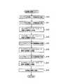
以下において、上り方向データの送信方法の詳細について、図面を参照しながら説明する。図5及び図6は、本発明の第1実施形態に係る上り方向データの送信方法の詳細を示す図である。 Details of the uplink data transmission method will be described below with reference to the drawings. 5 and 6 are diagrams illustrating details of the uplink data transmission method according to the first embodiment of the present invention.
図5(a)及び図5(b)に示すように、隣接キャリア間の送信電力差が最大送信電力差に基づいて設定される閾値を超えていない場合には、キャリア#1を用いた上り方向データ及びキャリア#2を用いた上り方向データは、時間軸で分割されずに多重化されて送信される。 As shown in FIG. 5A and FIG. 5B, when the transmission power difference between adjacent carriers does not exceed the threshold set based on the maximum transmission power difference, the uplink using
具体的には、無線基地局100は、キャリア1を用いた上り方向データを通常送信で送信することを指示する送信設定情報を、キャリア1を介して接続された無線通信端末10に送信する。同様に、無線基地局100は、キャリア2を用いた上り方向データを通常送信で送信することを指示する送信設定情報を、キャリア2を介して接続された無線通信端末10に送信する。 Specifically, the
図6(a)及び図6(b)に示すように、隣接キャリア間の送信電力差が最大送信電力差に基づいて設定される閾値を超える場合には、キャリア#1を用いた上り方向データ及びキャリア#2を用いた上り方向データは、時間軸で重複しないように分割して送信される。 As shown in FIG. 6A and FIG. 6B, when the transmission power difference between adjacent carriers exceeds the threshold set based on the maximum transmission power difference, the uplink data using
具体的には、無線基地局100は、キャリア1及びキャリア2を用いた上り方向データの送信に用いられる時間枠が重複しないように、キャリア1及びキャリア2に時間枠を割り当てる。続いて、無線基地局100は、キャリア1に割り当てられた時間枠を示しており、上り方向データを間欠送信で送信することを指示する送信設定情報を、キャリア1を介して接続された無線通信端末10に送信する。同様に、無線基地局100は、キャリア2に割り当てられた時間枠を示しており、上り方向データを間欠送信で送信することを指示する送信設定情報を、キャリア2を介して接続された無線通信端末10に送信する。 Specifically, the
(無線通信端末の動作)
以下において、本発明の第1実施形態に係る無線通信端末の動作について、図面を参照しながら説明する。図7は、本発明の第1実施形態に係る無線通信端末10の動作を示すフロー図である。なお、送信電力制御のメイン処理は、所定の周期で繰り返して実行される処理である。(Operation of wireless communication terminal)
Hereinafter, operations of the wireless communication terminal according to the first embodiment of the present invention will be described with reference to the drawings. FIG. 7 is a flowchart showing the operation of the
なお、以下においては、隣接キャリアがキャリア#1及びキャリア#2である場合を例に挙げて説明する。また、無線通信端末10は、キャリア#1及びキャリア#2を用いて上り方向データを一の無線基地局100に送信しているものとする。 In the following, the case where the adjacent carriers are
図7に示すように、ステップ10において、無線通信端末10は、キャリア#1を対象として、下り方向データの受信品質を測定する。具体的には、無線通信端末10は、キャリア#1を用いて送信する上り方向データの送信先である無線基地局100から受信した下り方向データの受信品質を測定する。 As shown in FIG. 7, in
ステップ11において、無線通信端末10は、キャリア#2を対象として、下り方向データの受信品質を測定する。具体的には、無線通信端末10は、キャリア#2を用いて送信する上り方向データの送信先である無線基地局100から受信した下り方向データの受信品質を測定する。 In step 11, the
ステップ12において、無線通信端末10は、キャリア#1を用いて送信する上り方向データの送信電力をオープンループ制御によって決定する。具体的には、無線通信端末10は、ステップ10で測定した受信品質に基づいて、キャリア#1を用いて送信する上り方向データの送信電力を決定する。 In
ステップ13において、無線通信端末10は、キャリア#2を用いて送信する上り方向データの送信電力をオープンループ制御によって決定する。具体的には、無線通信端末10は、ステップ11で測定した受信品質に基づいて、キャリア#2を用いて送信する上り方向データの送信電力を決定する。 In
ステップ14において、無線通信端末10は、キャリア#1について電力制御情報を受信する。具体的には、無線通信端末10は、キャリア#1を用いて送信する上り方向データの送信先である無線基地局100から電力制御情報を受信する。なお、電力制御情報は、キャリア#1を用いて送信する上り方向データの受信品質に基づいて無線基地局100が生成する情報である。 In
ステップ15において、無線通信端末10は、キャリア#1を用いて送信する上り方向データの送信電力をクローズドループ制御によって調整する。具体的には、無線通信端末10は、ステップ14で受信した電力制御情報に基づいて、ステップ12で決定した上り方向データの送信電力を調整する。 In step 15, the
すなわち、無線通信端末10は、オープンループ制御及びクローズドループ制御によって定められた送信電力で、キャリア#1を用いて上り方向データを送信する。 That is, the
ステップ16において、無線通信端末10は、キャリア#2について電力制御情報を受信する。具体的には、無線通信端末10は、キャリア#2を用いて送信する上り方向データの送信先である無線基地局100から電力制御情報を受信する。なお、電力制御情報は、キャリア#2を用いて送信する上り方向データの受信品質に基づいて無線基地局100が生成する情報である。 In
ステップ17において、無線通信端末10は、キャリア#2を用いて送信する上り方向データの送信電力をクローズドループ制御によって調整する。具体的には、無線通信端末10は、ステップ16で受信した電力制御情報に基づいて、ステップ13で決定した上り方向データの送信電力を調整する。 In
すなわち、無線通信端末10は、オープンループ制御及びクローズドループ制御によって定められた送信電力で、キャリア#2を用いて上り方向データを送信する。 That is, the
ステップ18において、無線通信端末10は、キャリア#1の送信電力を示す送信電力情報(送信電力値)及びキャリア#2の送信電力を示す送信電力情報(送信電力値)を無線基地局100に送信する。 In
(無線基地局の動作)
以下において、本発明の第1実施形態に係る無線基地局の動作について、図面を参照しながら説明する。図8は、本発明の第1実施形態に係る無線基地局100の動作を示すフロー図である。(Operation of wireless base station)
Hereinafter, the operation of the radio base station according to the first embodiment of the present invention will be described with reference to the drawings. FIG. 8 is a flowchart showing the operation of the
図8に示すように、ステップ20において、無線基地局100は、隣接キャリア(キャリア#1及びキャリア#2)について、上り方向データの送信電力の差(送信電力差)を算出する。 As shown in FIG. 8, in
ステップ21において、無線基地局100は、隣接キャリア間の送信電力差が最大送信電力差(MaxRLTxPwrDiff)に基づいて設定される閾値を超えるか否かを判定する。また、無線基地局100は、隣接キャリア間の送信電力差が最大送信電力差に基づいて設定される閾値を超える場合には、ステップ22の処理に移り、隣接キャリア間の送信電力差が最大送信電力差に基づいて設定される閾値を超えない場合には、ステップ23の処理に移る。 In step 21, the
ここで、最大送信電力差に基づいて設定される閾値とは、上述したように、最大送信電力差そのものであってもよく、最大送信電力差よりも小さい値(例えば、所定比率(0.9)を最大送信電力差に乗算した値)であってもよい。 Here, as described above, the threshold set based on the maximum transmission power difference may be the maximum transmission power difference itself, or a value smaller than the maximum transmission power difference (for example, a predetermined ratio (0.9 ) Multiplied by the maximum transmission power difference).
ステップ22において、無線基地局100は、隣接キャリアを用いた上り方向データを時間軸で重複しないように分割して送信する間欠送信を指示する送信設定情報を生成する。具体的には、無線基地局100は、キャリア1及びキャリア2を用いた上り方向データの送信に用いられる時間枠が重複しないように、キャリア1及びキャリア2に時間枠を割り当てる。続いて、無線基地局100は、キャリア1に割り当てられた時間枠を示しており、上り方向データを間欠送信で送信することを指示する送信設定情報をキャリア1用に生成する。同様に、無線基地局100は、キャリア2に割り当てられた時間枠を示しており、上り方向データを間欠送信で送信することを指示する送信設定情報をキャリア2用に生成する。 In
ステップ23において、無線基地局100は、上り方向データを間欠送信で送信することを送信設定情報によって無線通信端末10に指示しているか否かを判定する。また、無線基地局100は、上り方向データを間欠送信で送信することを指示している場合には、ステップ24の処理に移り、上り方向データを間欠送信で送信することを指示していない場合には、送信設定処理を終了する。 In step 23, the
ステップ24において、無線基地局100は、間欠送信を解除して、上り方向データを通常送信で送信することを指示する送信設定情報を生成する。具体的には、無線基地局100は、キャリア1を用いた上り方向データを通常送信で送信することを指示する送信設定情報をキャリア1用に生成する。同様に、無線基地局100は、キャリア2を用いた上り方向データを通常送信で送信することを指示する送信設定情報をキャリア2用に生成する。 In step 24, the
ステップ25において、無線基地局100は、ステップ22又はステップ24で生成した送信設定情報を無線通信端末10に送信する。具体的には、無線基地局100は、キャリア1用に生成した送信設定情報を、キャリア1を介して接続された無線通信端末10に送信する。同様に、無線基地局100は、キャリア2用に生成した送信設定情報を、キャリア2を介して接続された無線通信端末10に送信する。 In step 25, the
(作用・効果)
本発明の第1実施形態に係る無線基地局100によれば、電力制御情報生成部140は、隣接キャリア間の送信電力差が最大送信電力差(MaxRLTxPwrDiff)に基づいて設定される閾値を超える場合に、隣接キャリアを用いた上り方向データを時間軸で重複しないように分割して送信する間欠送信を指示する送信設定情報を生成して、隣接キャリアを介して接続された無線通信端末10に送信設定情報を送信する。(Action / Effect)
According to the
従って、所定の周波数間隔を有して隣接する隣接キャリア間の干渉を抑制しつつ、マルチキャリアによる通信を継続することができる。 Therefore, multicarrier communication can be continued while suppressing interference between adjacent carriers having a predetermined frequency interval.
[第2実施形態]
以下において、本発明の第2実施形態について説明する。なお、以下においては、上述した第1実施形態と第2実施形態との差異について主として説明する。[Second Embodiment]
In the following, a second embodiment of the present invention will be described. In the following, differences between the first embodiment and the second embodiment described above will be mainly described.
具体的には、上述した第1実施形態では、無線基地局100は、隣接キャリア間の送信電力差が最大送信電力差に基づいて設定される閾値を超える場合に、隣接キャリアを用いた上り方向データを時間軸で重複しないように分割して送信する間欠送信を無線通信端末10に指示する。 Specifically, in the first embodiment described above, the
これに対して、第2実施形態では、無線基地局100は、隣接キャリア間の送信電力差が推定曲線差閾値を超えているか否かを判定するとともに、隣接キャリア間の送信電力差が推定曲線差閾値を超えており、かつ、隣接キャリア間の送信電力差が最大送信電力差に基づいて設定される閾値を超える場合に、隣接キャリアを用いた上り方向データを時間軸で重複しないように分割して送信する間欠送信を無線通信端末10に指示する。 On the other hand, in the second embodiment, the
(無線基地局の構成)
以下において、本発明の第2実施形態に係る無線基地局の構成について、図面を参照しながら説明する。図9は、本発明の第2実施形態に係る無線基地局100を示す機能ブロック構成図である。なお、図9では、図4と同様の構成については同様の符号を付している点に留意すべきである。(Configuration of radio base station)
The configuration of the radio base station according to the second embodiment of the present invention will be described below with reference to the drawings. FIG. 9 is a functional block configuration diagram showing a
図9に示すように、無線基地局100は、受信部110、送信電力差算出部120、受信品質測定部130、電力制御情報生成部140及び送信設定情報生成部150に加えて、送信電力差判定部160を有する。 As illustrated in FIG. 9, the
送信電力差算出部120は、所定の周期(例えば、受信部110が送信電力情報を受信する周期)毎に隣接キャリア間の送信電力差を算出する。 The transmission power
送信電力差判定部160は、送信電力差算出部120によって所定の周期毎に算出された隣接キャリア間の送信電力差が増大しているか否かを判定する。具体的には、送信電力差判定部160は、上り方向データの送信電力に基づいて、時間軸上において上り方向データの送信電力が変化する状況を示す推定曲線を隣接キャリア毎に算出する。続いて、送信電力差判定部160は、各隣接キャリア間の推定曲線の差(以下、推定曲線差)が所定期間に亘って推定曲線差閾値を超えているか否かを判定する。なお、送信電力差判定部160は、隣接キャリア間の推定曲線差が所定期間に亘って推定曲線閾値を超えている場合には、隣接キャリア間の推定曲線差が所定期間に亘って推定曲線閾値を超えている旨を電力制御情報生成部140に通知する。 The transmission power
例えば、隣接キャリアがキャリア#1及びキャリア#2である場合を例に挙げて、図10を参照しながら、キャリア#1及びキャリア#2の推定曲線差を算出する手順について説明する。なお、以下においては、キャリア#1の送信電力はキャリア#2の送信電力よりも大きい場合について考える。 For example, taking the case where the adjacent carriers are
なお、ノッチ期間は、受信強度や受信品質(SIR)に基づいて算出されるノッチ間隔によって定められる。具体的には、ノッチ期間は、送信電力推定曲線のピークポイント前のノッチ間隔及びピークポイント後のノッチ間隔を含む。ここで、ノッチ期間において、無線基地局100は、隣接キャリア間の推定曲線差が所定期間に亘って推定曲線閾値を超えている場合に、隣接キャリアの少なくともいずれか一方に対応する待機フラグに“1”をセットする。 Note that the notch period is determined by a notch interval calculated based on reception intensity and reception quality (SIR). Specifically, the notch period includes a notch interval before the peak point and a notch interval after the peak point of the transmission power estimation curve. Here, in the notch period, when the estimated curve difference between adjacent carriers exceeds the estimated curve threshold for a predetermined period, the
具体的には、キャリア#1の送信電力を“P#1(t)”とした場合に、キャリア#1の推定曲線“M#1(t)”が以下の式(1)によって算出される。なお、αは、キャリア#1に対応する係数である。Specifically, when the transmission power of

なお、推定曲線差“Pdiff”は、推定曲線“M#1(t)”と下方推定曲線“M’#2(t)”との差ではなくて、単に、推定曲線“M#1(t)”と推定曲線“M#2(t)”との差であってもよいことは勿論である。Note that the estimated curve difference “Pdiff ” is not the difference between the estimated curve “M# 1 (t)” and the lower estimated curve “M ′# 2 (t)”, but simply the estimated curve “M# 1 ( t) "and the estimated curve" M# 2 (t) "may of course be different.
なお、送信電力差判定部160は、ノッチ期間において推定曲線差“Pdiff”が推定曲線差閾値(Pthresh)を超えるか否かを判定してもよい。The transmission power
送信設定情報生成部150は、隣接キャリア間の推定曲線差が所定期間に亘って推定曲線閾値を超えている旨及び隣接キャリア間の送信電力差が最大送信電力差に基づいて設定される閾値を超えた旨が通知された場合には、隣接キャリアを用いた上り方向データを時間軸で重複しないように分割して送信する間欠送信を無線通信端末10に指示する送信設定情報を生成する。 The transmission setting
(無線基地局の動作)
以下において、本発明の第2実施形態に係る無線基地局の動作について、図面を参照しながら説明する。図11は、本発明の第2実施形態に係る無線基地局100の動作を示すフロー図である。なお、図11に示す送信設定処理は、上述した図8に示した送信設定処理に代えて実行される処理である。(Operation of wireless base station)
The operation of the radio base station according to the second embodiment of the present invention will be described below with reference to the drawings. FIG. 11 is a flowchart showing an operation of the
なお、以下においては、上述した第1実施形態と同様に、隣接キャリアがキャリア#1及びキャリア#2である場合を例に挙げて説明する。また、無線通信端末10は、キャリア#1及びキャリア#2を用いて上り方向データを無線基地局100に送信しているものとする。さらに、キャリア#1の送信電力はキャリア#2の送信電力よりも大きいものとする。 In the following, as in the first embodiment described above, the case where adjacent carriers are
図11に示すように、ステップ30において、無線基地局100は、キャリア#1の送信電力を示す送信電力情報を無線通信端末10から受信する。続いて、無線基地局100は、送信電力が高いキャリア#1を介して送信される上り方向データの送信電力に基づいて、キャリア#1の推定曲線を算出する。 As shown in FIG. 11, in step 30,
ステップ31において、無線基地局100は、キャリア#2の送信電力を示す送信電力情報を無線通信端末10から受信する。続いて、無線基地局100は、送信電力が低いキャリア#2を介して送信される上り方向データの送信電力に基づいて、キャリア#2の推定曲線(又は、下方推定曲線)を算出する。 In step 31, the
ステップ32において、無線基地局100は、キャリア#1及びキャリア#2の送信電力差が推定曲線差閾値を超えているか否かを判定する。具体的には、無線基地局100は、ステップ30で算出されたキャリア#1の推定曲線とステップ31で算出されたキャリア#2の推定曲線(又は、下方推定曲線)との差(推定曲線差)を算出する。続いて、無線基地局100は、推定曲線差が所定期間に亘って推定曲線差閾値を超えているか否かを判定する。 In step 32, the
また、無線基地局100は、推定曲線差が所定期間に亘って推定曲線差閾値を超えている場合には、ステップ33の処理に移る。一方、無線基地局100は、推定曲線差が所定期間に亘って推定曲線差閾値を超えていない場合には、ステップ35の処理に移る。 On the other hand, when the estimated curve difference exceeds the estimated curve difference threshold for a predetermined period, the
ステップ33において、無線基地局100は、キャリア#1及びキャリア#2の送信電力差が最大送信電力差に基づいて設定される閾値を超えているか否かを判定する。また、無線基地局100は、送信電力差が最大送信電力差に基づいて設定される閾値を超えている場合には、ステップ34の処理に移り、送信電力差が最大送信電力差に基づいて設定される閾値を超えていない場合には、ステップ35の処理に移る。 In step 33, the
ステップ34において、無線基地局100は、隣接キャリアを用いた上り方向データを時間軸で重複しないように分割して送信する間欠送信を指示する送信設定情報を生成する。具体的には、無線基地局100は、キャリア1及びキャリア2を用いた上り方向データの送信に用いられる時間枠が重複しないように、キャリア1及びキャリア2に時間枠を割り当てる。続いて、無線基地局100は、キャリア1に割り当てられた時間枠を示しており、上り方向データを間欠送信で送信することを指示する送信設定情報をキャリア1用に生成する。同様に、無線基地局100は、キャリア2に割り当てられた時間枠を示しており、上り方向データを間欠送信で送信することを指示する送信設定情報をキャリア2用に生成する。 In step 34, the
ステップ35において、無線基地局100は、上り方向データを間欠送信で送信することを送信設定情報によって無線通信端末10に指示しているか否かを判定する。また、無線基地局100は、上り方向データを間欠送信で送信することを指示している場合には、ステップ36の処理に移り、上り方向データを間欠送信で送信することを指示していない場合には、送信設定処理を終了する。 In step 35, the
ステップ36において、無線基地局100は、間欠送信を解除して、上り方向データを通常送信で送信することを指示する送信設定情報を生成する。具体的には、無線基地局100は、キャリア1を用いた上り方向データを通常送信で送信することを指示する送信設定情報をキャリア1用に生成する。同様に、無線基地局100は、キャリア2を用いた上り方向データを通常送信で送信することを指示する送信設定情報をキャリア2用に生成する。 In step 36, the
ステップ37において、無線基地局100は、ステップ34又はステップ36で生成した送信設定情報を無線通信端末10に送信する。具体的には、無線基地局100は、キャリア1用に生成した送信設定情報を、キャリア1を介して接続された無線通信端末10に送信する。同様に、無線基地局100は、キャリア2用に生成した送信設定情報を、キャリア2を介して接続された無線通信端末10に送信する。 In step 37, the
(作用及び効果)
本発明の第2実施形態に係る無線基地局100によれば、電力制御情報生成部140が、単に隣接キャリア間の送信電力差が最大送信電力差に基づいて設定される閾値を超えた場合ではなくて、隣接キャリア間の送信電力差が推定曲線差閾値を超えており、かつ、隣接キャリア間の送信電力差が最大送信電力差に基づいて設定される閾値を超えた場合に、隣接キャリアを用いた上り方向データを時間軸で重複しないように分割して送信する間欠送信を無線通信端末10に指示する。(Function and effect)
According to the
ここで、例えば、フェージングなどの影響による受信品質の劣化に伴って、オープンループ制御やクローズドループ制御によってキャリアの送信電力が一時的に増大する場合が考えられる。このような場合には、隣接キャリア間の送信電力差が最大送信電力差に基づいて設定される閾値を一時的に超えたとしても、フェージングなどの影響が解消すれば、隣接キャリア間の送信電力差が最大送信電力差内に収まる可能性が高い。 Here, for example, there may be a case where the transmission power of the carrier temporarily increases due to open-loop control or closed-loop control as reception quality deteriorates due to fading or the like. In such a case, even if the transmission power difference between adjacent carriers temporarily exceeds the threshold set based on the maximum transmission power difference, the transmission power between adjacent carriers can be eliminated if the effect of fading is resolved. The difference is likely to be within the maximum transmission power difference.
本発明の第2実施形態では、このように、隣接キャリア間の送信電力差が最大送信電力差に基づいて設定される閾値を一時的に超えるような場合に、不必要な間欠送信が行われることを抑制できる。 In the second embodiment of the present invention, unnecessary intermittent transmission is performed when the transmission power difference between adjacent carriers temporarily exceeds a threshold set based on the maximum transmission power difference. This can be suppressed.
[第3実施形態]
以下において、本発明の第3実施形態について説明する。なお、以下においては、上述した第1実施形態と第3実施形態との差異について主として説明する。[Third Embodiment]
In the following, a third embodiment of the present invention will be described. In the following, differences between the first embodiment and the third embodiment described above will be mainly described.
具体的には、上述した第1実施形態では、隣接キャリアを用いた上り方向データを時間軸で重複しないように分割して送信する間欠送信を指示するか否かを無線基地局100が判定している。 Specifically, in the first embodiment described above, the
これに対して、第3実施形態では、隣接キャリアを用いた上り方向データを時間軸で重複しないように分割して送信する間欠送信を指示するか否かを基地局制御装置200が判定して、基地局制御装置200は、上り方向データの間欠送信を無線基地局100を介して無線通信端末10に指示する。 In contrast, in the third embodiment, the base
(基地局制御装置の構成)
以下において、本発明の第3実施形態に係る基地局制御装置の構成について、図面を参照しながら説明する。図12は、本発明の第3実施形態に係る基地局制御装置200を示す機能ブロック構成図である。(Configuration of base station controller)
The configuration of the base station control apparatus according to the third embodiment of the present invention will be described below with reference to the drawings. FIG. 12 is a functional block configuration diagram showing a base
図12に示すように、基地局制御装置200は、基地局制御装置200は、送信電力情報受信部210と、送信電力差算出部220と、送信設定指示部230とを有する。 As illustrated in FIG. 12, the base
送信電力情報受信部210は、隣接キャリア(上り方向データ)の送信電力をそれぞれ示す送信電力情報を無線基地局100から受信する。 The transmission power
例えば、キャリア#1について無線通信端末10が無線基地局100aと接続しており、キャリア#2について無線通信端末10が無線基地局100bと接続している場合を例に挙げると、送信電力情報受信部210は、キャリア#1の送信電力を示す送信電力情報を無線基地局100aから受信し、キャリア#2の送信電力を示す送信電力情報を無線基地局100bから受信する。 For example, when the
なお、送信電力情報受信部210は、キャリア#1及びキャリア#2の送信電力をそれぞれ示す送信電力情報を無線基地局100aからまとめて受信してもよい。同様に、送信電力情報受信部210は、キャリア#1及びキャリア#2の送信電力をそれぞれ示す送信電力情報を無線基地局100bからまとめて受信してもよい。 Note that the transmission power
送信電力差算出部220は、送信電力情報受信部210が受信した送信電力情報に基づいて、隣接キャリアの送信電力の差(以下、送信電力差)を算出する。また、送信電力差算出部220は、隣接キャリア間において許容される最大送信電力差(MaxRLTxPwrDiff)に基づいて設定される閾値を隣接キャリア間の送信電力差が超えるか否かを判定する。なお、送信電力差算出部220は、隣接キャリア間の送信電力差が最大送信電力差に基づいて設定される閾値を超える場合には、隣接キャリア間の送信電力差が最大送信電力差に基づいて設定される閾値を超えた旨を送信設定指示部230に通知する。 Based on the transmission power information received by the transmission power
送信設定指示部230は、隣接キャリア間の送信電力差が最大送信電力差に基づいて設定される閾値を超えた旨が通知された場合には、隣接キャリアを用いた上り方向データを時間軸で重複しないように分割して送信する間欠送信を、無線基地局100を介して無線通信端末10に指示する。 When notified that the transmission power difference between adjacent carriers exceeds a threshold set based on the maximum transmission power difference, the transmission
(作用及び効果)
本発明の第3実施形態に係る基地局制御装置200によれば、送信設定指示部230は、隣接キャリア間の送信電力差が最大送信電力差に基づいて設定される閾値を超えた旨が通知された場合に、隣接キャリアを用いた上り方向データを時間軸で重複しないように分割して送信する間欠送信を指示する。(Function and effect)
According to the base
従って、所定の周波数間隔を有して隣接する隣接キャリア間の干渉を抑制しつつ、マルチキャリアによる通信を継続することができる。 Therefore, multicarrier communication can be continued while suppressing interference between adjacent carriers having a predetermined frequency interval.
また、隣接キャリアを介して無線通信端末10が異なる無線基地局100と接続されている場合であっても、隣接キャリアを用いた上り方向データを時間軸で重複しないように分割して送信する間欠送信を、無線基地局100を介して無線通信端末10に指示するため、隣接キャリア間の干渉を抑制しつつ、マルチキャリアによる通信を継続することができる。 Further, even when the
[第4実施形態]
以下において、本発明の第4実施形態について説明する。なお、以下においては、上述した第1実施形態と第4実施形態との差異について主として説明する。[Fourth Embodiment]
Hereinafter, a fourth embodiment of the present invention will be described. In the following, differences between the first embodiment and the fourth embodiment described above will be mainly described.
具体的には、上述した第1実施形態では、無線基地局100は、隣接キャリア間の送信電力差が最大送信電力差に基づいて設定される閾値を超える場合に、隣接キャリアを用いた上り方向データを時間軸で重複しないように分割して送信する間欠送信を無線通信端末10に指示する。 Specifically, in the first embodiment described above, the
これに対して、第4実施形態では、無線基地局100は、隣接キャリア間の送信電力差が最大送信電力差に基づいて設定される閾値を超える場合に、隣接キャリアのうち、送信電力が大きいキャリアを用いた上り方向データの送信を、隣接キャリア間の送信電力差が最大送信電力差に基づいて設定される閾値以下となるまでの一定期間に亘って停止することを無線通信端末10に指示する。 On the other hand, in the fourth embodiment, the
(無線基地局の動作)
以下において、本発明の第4実施形態に係る無線基地局の動作について、図面を参照しながら説明する。図13は、本発明の第4実施形態に係る無線基地局100の動作を示すフロー図である。なお、図13に示す送信設定処理は、上述した図8に示した送信設定処理に代えて実行される処理である。(Operation of wireless base station)
The operation of the radio base station according to the fourth embodiment of the present invention will be described below with reference to the drawings. FIG. 13 is a flowchart showing the operation of the
図13に示すように、ステップ40において、無線基地局100は、隣接キャリア(キャリア#1及びキャリア#2)について、上り方向データの送信電力の差(送信電力差)を算出する。 As illustrated in FIG. 13, in step 40, the
ステップ41において、無線基地局100は、隣接キャリア間の送信電力差が最大送信電力差(MaxRLTxPwrDiff)に基づいて設定される閾値を超えるか否かを判定する。また、無線基地局100は、隣接キャリア間の送信電力差が最大送信電力差に基づいて設定される閾値を超える場合には、ステップ42の処理に移り、隣接キャリア間の送信電力差が最大送信電力差に基づいて設定される閾値を超えない場合には、ステップ47の処理に移る。 In step 41, the
ここで、最大送信電力差に基づいて設定される閾値とは、上述したように、最大送信電力差そのものであってもよく、最大送信電力差よりも小さい値(例えば、所定比率(0.9)を最大送信電力差に乗算した値)であってもよい。 Here, as described above, the threshold set based on the maximum transmission power difference may be the maximum transmission power difference itself, or a value smaller than the maximum transmission power difference (for example, a predetermined ratio (0.9 ) Multiplied by the maximum transmission power difference).
ステップ42において、無線基地局100は、隣接キャリアのうち、送信電力が大きいキャリアを用いた上り方向データの送信を停止する送信停止が設定されているか否かを判定する。また、無線基地局100は、送信停止が設定されている場合にはステップ45の処理に移り、送信停止が設定されていない場合にはステップ43の処理に移る。 In step 42, the
ステップ43において、無線基地局100は、隣接キャリアのうち、送信電力が大きいキャリアを用いた上り方向データの送信を停止する送信停止を指示する送信設定情報を生成する。 In step 43, the
ステップ44において、無線基地局100は、所定の待ち時間をタイマにセットする。ここで、所定の待ち時間とは、無線基地局100がキャリアの切断を決断する無通信時間よりも短い時間であって、隣接キャリアのうち、送信電力が大きいキャリアを維持することが許容される時間である。 In step 44, the
ステップ45において、無線基地局100は、所定の待ち時間がセットされたタイマがタイムアウトしたか否かを判定する。また、無線基地局100は、タイマがタイムアウトした場合にはステップ46の処理に移り、タイマがタイムアウトしていない場合にはステップ49の処理に移る。 In step 45, the
ステップ46において、無線基地局100は、隣接キャリアのうち、送信電力が大きいキャリアを用いた上り方向データの暫定的に送信する暫定送信を指示する送信設定情報を生成する。なお、暫定送信とは、隣接キャリアのうち、送信電力が大きいキャリアを維持するために、送信時間が短時間である上り方向データを送信することである。また、暫定送信では、無線基地局100は、隣接キャリア間の送信電力差が最大送信電力差を越えない送信電力で上り方向データを送信することを無線通信端末10に指示する。 In step 46, the
ステップ47において、無線基地局100は、隣接キャリアのうち、送信電力が大きいキャリアを用いた上り方向データの送信を停止する送信停止が設定されているか否かを判定する。また、無線基地局100は、送信停止が設定されている場合にはステップ48の処理に移り、送信停止が設定されていない場合にはステップ49の処理に移る。 In step 47, the
ステップ48において、無線基地局100は、隣接キャリアのうち、送信電力が大きいキャリアを用いた上り方向データの送信停止の解除を指示する送信設定情報を生成する。 In step 48, the
ステップ49において、無線基地局100は、ステップ43、ステップ46又はステップ48で生成した送信設定情報を無線通信端末10に送信する。 In step 49, the
なお、無線基地局100は、上り方向データの送信停止が一定期間内に解除されない場合には、すなわち、一定期間を過ぎても、隣接キャリア間の送信電力差が最大送信電力差に基づいて設定される閾値以下とならない場合には、隣接キャリアのうち、送信電力が大きいキャリアの切断を無線通信端末10に指示する。 Note that the
(作用及び効果)
本発明の第4実施形態に係る無線基地局100によれば、無線基地局100は、隣接キャリア間の送信電力差が最大送信電力差に基づいて設定される閾値を超える場合に、隣接キャリアのうち、送信電力が大きいキャリアを用いた上り方向データの送信を、隣接キャリア間の送信電力差が最大送信電力差に基づいて設定される閾値以下となるまでの一定期間に亘って停止することを無線通信端末10に指示する。(Function and effect)
According to the
従って、所定の周波数間隔を有して隣接する隣接キャリア間の干渉を抑制しつつ、マルチキャリアによる通信を継続することができる。 Therefore, multicarrier communication can be continued while suppressing interference between adjacent carriers having a predetermined frequency interval.
また、無線基地局100は、隣接キャリアのうち、送信電力が大きいキャリアを用いた上り方向データの送信停止を指示している場合であっても、タイマがタイムアウトした場合に、上り方向データの暫定送信を指示する。 In addition, even when the
従って、隣接キャリアのうち、送信電力が大きいキャリアの切断を防止することができる。 Therefore, it is possible to prevent a disconnection of a carrier having a large transmission power among adjacent carriers.
(その他の実施形態)
上述したように、本発明の一実施形態を通じて本発明の内容を開示したが、この開示の一部をなす論述及び図面は、本発明を限定するものであると理解すべきではない。この開示から当業者には様々な代替実施の形態が明らかとなろう。(Other embodiments)
As described above, the content of the present invention has been disclosed through one embodiment of the present invention. However, it should not be understood that the description and drawings constituting a part of this disclosure limit the present invention. From this disclosure, various alternative embodiments will be apparent to those skilled in the art.
例えば、上述した第1実施形態〜第4実施形態では、隣接キャリア間の送信電力差が最大送信電力差に基づいて設定される閾値を超えているか否かに基づいて、隣接キャリアを用いた上り方向データを時間軸で重複しないように分割して送信する間欠送信を指示するが、これに限定されるものではない。 For example, in the first to fourth embodiments described above, uplink using adjacent carriers is based on whether or not the transmission power difference between adjacent carriers exceeds a threshold set based on the maximum transmission power difference. Although intermittent transmission in which direction data is divided and transmitted so as not to overlap on the time axis is instructed, the present invention is not limited to this.
具体的には、互いに隣接していない2つのキャリアの送信電力差が所定の閾値を超えているか否かに基づいて、2つのキャリアを用いた上り方向データを時間軸で重複しないように分割して送信する間欠送信を指示してもよい。 Specifically, based on whether or not the transmission power difference between two carriers that are not adjacent to each other exceeds a predetermined threshold, the uplink data using the two carriers is divided so as not to overlap on the time axis. Intermittent transmission may be instructed.
この場合には、所定の閾値は、2つのキャリアの中心周波数がどの程度離れているかに応じて定められる。具体的には、2つのキャリアの中心周波数が離れていれば離れているほど、2つのキャリアが干渉する程度も低くなるため、所定の閾値は低い値として定められる。 In this case, the predetermined threshold is determined according to how far the center frequencies of the two carriers are separated. Specifically, the farther the center frequency of the two carriers is, the lower the degree of interference between the two carriers is. Therefore, the predetermined threshold value is set as a low value.
また、上述した第1実施形態、第2実施形態及び第4実施形態に係る無線基地局100の動作は、コンピュータにおいて実行可能なプログラムとしても提供することができる。 Further, the operation of the
また、上述した第1実施形態〜第4実施形態では特に触れていないが、間欠送信を指示する送信設定情報は、隣接キャリアのうち、送信電力が大きいキャリアを用いた上り方向データの送信を停止するスロット数を示す情報であってもよい。なお、隣接キャリアのうち、送信電力が小さいキャリアを用いた上り方向データの送信は、送信電力が大きいキャリアを用いた上り方向データの送信を停止するスロットで行われる。 In addition, although not particularly mentioned in the first to fourth embodiments described above, transmission setting information instructing intermittent transmission stops transmission of uplink data using a carrier having a large transmission power among adjacent carriers. It may be information indicating the number of slots to be played. Note that uplink data transmission using a carrier having low transmission power among adjacent carriers is performed in a slot in which transmission of uplink data using a carrier having high transmission power is stopped.
この場合において、隣接キャリア間の送信電力差が大きければ大きいほど、送信電力が大きいキャリアを用いた上り方向データの送信を停止するスロット数が長く設定されることが好ましい。 In this case, it is preferable that the larger the transmission power difference between adjacent carriers is, the longer the number of slots for stopping transmission of uplink data using a carrier with higher transmission power is set.
さらに、同一の無線基地局に収容され、隣接キャリア間の送信電力差が最大送信電力差に基づいて設定される閾値を超える複数の無線通信端末間において、上述した間欠送信を同期させることによって、無線通信端末間のキャリアの干渉を抑制することができる。 Furthermore, by synchronizing the intermittent transmission described above between a plurality of wireless communication terminals that are accommodated in the same wireless base station and whose transmission power difference between adjacent carriers exceeds a threshold set based on the maximum transmission power difference, Carrier interference between wireless communication terminals can be suppressed.
また、隣接する複数の無線基地局間で、該複数の無線基地局がそれぞれに収容する無線通信端末に対して、上述した間欠送信を同期させることによって、無線基地局の制御エリアを跨いだ無線通信端末間のキャリアの干渉を抑制することができる。 In addition, by synchronizing the intermittent transmission described above with respect to the wireless communication terminals accommodated in each of the plurality of adjacent wireless base stations, the wireless communication over the control area of the wireless base station Carrier interference between communication terminals can be suppressed.
このように、本発明は、ここでは記載していない様々な実施の形態などを含むことは勿論である。したがって、本発明の技術的範囲は、上述の説明から妥当な特許請求の範囲に係る発明特定事項によってのみ定められるものである。 As described above, the present invention naturally includes various embodiments that are not described herein. Therefore, the technical scope of the present invention is defined only by the invention specifying matters according to the scope of claims reasonable from the above description.
10・・・無線通信端末、11・・・アンテナ、12・・・RF/IF変換器、13・・・パワーアンプ、14・・・音声入出力部、14a・・・マイク、14b・・・スピーカ、15・・・映像入出力部、15a・・・カメラ、15b・・・表示部、16・・・コーデック処理部、16a・・・音声コーデック処理部、16b・・・映像コーデック処理部、17・・・ベースバンド処理部、18・・・操作部、19・・・メモリ、20・・・制御部、100・・・無線基地局、110・・・受信部、120・・・送信電力差算出部、130・・・受信品質測定部、140・・・電力制御情報生成部、150・・・送信設定情報生成部、160・・・送信部、170・・・送信電力差判定部、200・・・基地局制御装置、210・・・送信電力情報受信部、220・・・送信電力差算出部、230・・・送信設定指示部、300・・・通信システム DESCRIPTION OF
Claims (4)
Translated fromJapanese前記第1のキャリアを介して接続された無線通信端末から前記第1のキャリアの送信電力値を取得するステップと、
前記第2のキャリアを介して接続された無線通信端末から前記第2のキャリアの送信電力値を取得するステップと、
前記第1のキャリアの送信電力値と、前記第2のキャリアの送信電力値との送信電力差を算出するステップと、
前記送信電力差が、前記第1のキャリアと前記第2のキャリアとの間において許容される最大送信電力差に基づいて設定される閾値を超えるか否かを判定するステップと、
前記送信電力差が前記最大送信電力差に基づいて設定される閾値を超える場合、前記第1のキャリアを用いた上り方向データの送信に用いられる第1時間枠及び前記第2のキャリアを用いた上り方向データの送信に用いられる第2時間枠を、時間軸で重複しないように分割して割り当てるステップと、
前記第1のキャリアを介して接続された無線通信端末に対して前記第1時間枠を通知するステップと、
前記第2のキャリアを介して接続された無線通信端末に対して前記第2時間枠を通知するステップと
を備える無線通信方法。A wireless communication method in the uplink direction by a multicarrier using at least a first carrier and a second carrier adjacent to the first carrier with a predetermined frequency interval,
Obtaining a transmission power value of the first carrier from a wireless communication terminal connected via the first carrier;
Obtaining a transmission power value of the second carrier from a wireless communication terminal connected via the second carrier;
Calculating a transmission power difference between the transmission power value of the first carrier and the transmission power value of the second carrier;
Determining whether the transmission power difference exceeds a threshold set based on a maximum transmission power difference allowed between the first carrier and the second carrier;
When the transmission power difference exceeds a threshold set based on the maximum transmission power difference, the first time frame used for uplink data transmission using the first carrier and the second carrier are used. Dividing and assigning a second time frame used for transmission of uplink data so as not to overlap on the time axis;
Notifying the first time frame to a wireless communication terminal connected via the first carrier;
And a step of notifying the second time frame to a wireless communication terminal connected via the second carrier.
前記所定の周期ごとに算出された前記送信電力差に基づいて、前記送信電力差が増大しているか否かを判定するステップを備え、
前記第1時間枠及び前記第2時間枠を割り当てるステップでは、前記送信電力差に基づいて設定される閾値が増大していると判定された場合、前記第1時間枠及び前記第2時間枠を時間軸上で重複しないように分割して割り当てる請求項1に記載の無線通信方法。In the step of calculating the transmission power difference, the transmission power difference is calculated at a predetermined period,
Determining whether or not the transmission power difference is increased based on the transmission power difference calculated for each predetermined period;
In the step of assigning the first time frame and the second time frame, when it is determined that a threshold set based on the transmission power difference is increased, the first time frame and the second time frame are set. The wireless communication method according to claim 1, wherein the wireless communication method is divided and assigned so as not to overlap on the time axis.
前記第1のキャリアを介して接続された無線通信端末から前記第1のキャリアの送信電力値を取得し、前記第2のキャリアを介して接続された無線通信端末から前記第2のキャリアの送信電力値を取得する取得部と、
前記第1のキャリアの送信電力値と、前記第2のキャリアの送信電力値との送信電力差を算出する送信電力差算出部と、
前記送信電力差算出部によって算出された前記送信電力差が、前記第1のキャリアと前記第2のキャリアとの間において許容される最大送信電力差に基づいて設定される閾値を超えるか否かを判定する送信電力差判定部と、
前記送信電力差判定部によって前記送信電力差が前記最大送信電力差に基づいて設定される閾値を超えると判定された場合、前記第1のキャリアを用いた上り方向データの送信に用いられる第1時間枠及び前記第2のキャリアを用いた上り方向データの送信に用いられる第2時間枠を、時間軸で重複しないように分割して割り当てる割当部と、
前記第1のキャリアを介して接続された無線通信端末に対して前記第1時間枠を通知し、前記第2のキャリアを介して接続された無線通信端末に対して前記第2時間枠を通知する通知部と
を備える無線基地局。A radio base station connected to a radio communication terminal by a multicarrier using at least a first carrier and a second carrier adjacent to the first carrier with a predetermined frequency interval,
The transmission power value of the first carrier is acquired from the wireless communication terminal connected via the first carrier, and the second carrier is transmitted from the wireless communication terminal connected via the second carrier. An acquisition unit for acquiring an electric power value;
A transmission power difference calculator that calculates a transmission power difference between the transmission power value of the first carrier and the transmission power value of the second carrier;
Whether or not the transmission power difference calculated by the transmission power difference calculation unit exceeds a threshold set based on a maximum transmission power difference allowed between the first carrier and the second carrier A transmission power difference determination unit for determining
When the transmission power difference determination unit determines that the transmission power difference exceeds a threshold set based on the maximum transmission power difference, a first used for transmission of uplink data using the first carrier An allocation unit that divides and allocates a second time frame used for transmission of uplink data using the time frame and the second carrier so as not to overlap on the time axis;
The wireless communication terminal connected via the first carrier is notified of the first time frame, and the wireless communication terminal connected via the second carrier is notified of the second time frame. A radio base station.
前記送信電力差算出部によって前記所定の周期ごとに算出された前記送信電力差に基づいて、前記送信電力差が増大しているか否かを判定する電力差傾向判定部をさらに備え、
前記割当部は、前記電力差傾向判定部によって前記送信電力差が増大していると判定された場合、前記第1時間枠及び前記第2時間枠を時間軸で重複しないように分割して割り当てる請求項3に記載の無線基地局。The transmission power difference calculation unit calculates the transmission power difference at a predetermined period,
A power difference tendency determination unit that determines whether or not the transmission power difference is increased based on the transmission power difference calculated for each predetermined period by the transmission power difference calculation unit;
The allocation unit divides and allocates the first time frame and the second time frame so as not to overlap on the time axis when the transmission power difference determination unit determines that the transmission power difference is increasing. The radio base station according to claim 3.
Priority Applications (5)
| Application Number | Priority Date | Filing Date | Title |
|---|---|---|---|
| JP2006233803AJP4829049B2 (en) | 2006-08-30 | 2006-08-30 | Wireless communication method and wireless base station |
| PCT/JP2007/066813WO2008026662A1 (en) | 2006-08-30 | 2007-08-29 | Wireless communication method and wireless base station |
| CN2007800322766ACN101513106B (en) | 2006-08-30 | 2007-08-29 | Wireless communication method and wireless base station |
| US12/439,150US8442575B2 (en) | 2006-08-30 | 2007-08-29 | Radio communication method and radio base station |
| KR1020097005246AKR101016149B1 (en) | 2006-08-30 | 2007-08-29 | Wireless communication method and wireless base station |
Applications Claiming Priority (1)
| Application Number | Priority Date | Filing Date | Title |
|---|---|---|---|
| JP2006233803AJP4829049B2 (en) | 2006-08-30 | 2006-08-30 | Wireless communication method and wireless base station |
Publications (2)
| Publication Number | Publication Date |
|---|---|
| JP2008060794A JP2008060794A (en) | 2008-03-13 |
| JP4829049B2true JP4829049B2 (en) | 2011-11-30 |
Family
ID=39135944
Family Applications (1)
| Application Number | Title | Priority Date | Filing Date |
|---|---|---|---|
| JP2006233803AExpired - Fee RelatedJP4829049B2 (en) | 2006-08-30 | 2006-08-30 | Wireless communication method and wireless base station |
Country Status (5)
| Country | Link |
|---|---|
| US (1) | US8442575B2 (en) |
| JP (1) | JP4829049B2 (en) |
| KR (1) | KR101016149B1 (en) |
| CN (1) | CN101513106B (en) |
| WO (1) | WO2008026662A1 (en) |
Families Citing this family (13)
| Publication number | Priority date | Publication date | Assignee | Title |
|---|---|---|---|---|
| JP4641513B2 (en)* | 2006-06-29 | 2011-03-02 | 京セラ株式会社 | Wireless communication method and wireless communication terminal |
| US8706133B2 (en)* | 2008-06-30 | 2014-04-22 | Motorola Solutions, Inc. | Threshold selection for broadcast signal detection |
| EP3609246B1 (en)* | 2009-02-13 | 2023-05-17 | Telefonaktiebolaget LM Ericsson (publ) | Controlling energy consumption of a wireless network node |
| JP2012124967A (en)* | 2009-04-27 | 2012-06-28 | Ntt Docomo Inc | User equipment, base station device, and communication control method |
| JP5023170B2 (en)* | 2009-04-27 | 2012-09-12 | 株式会社エヌ・ティ・ティ・ドコモ | User apparatus, base station apparatus, and communication control method |
| EP2670191A4 (en)* | 2011-01-27 | 2017-02-08 | Nec Corporation | Base station, mobile station, communication control system and method of controlling communication |
| JP5867778B2 (en)* | 2011-10-26 | 2016-02-24 | ソニー株式会社 | Transmitting apparatus, transmitting method, receiving apparatus, receiving method, and program |
| CN104902555B (en) | 2011-12-19 | 2018-04-20 | 华为技术有限公司 | A kind of method for controlling uplink transmission power and user equipment |
| US9253782B2 (en)* | 2012-05-11 | 2016-02-02 | Qualcomm Incorporated | Coexistence between LCTS and NCTS |
| CN103634887B (en)* | 2012-08-24 | 2018-03-09 | 华为技术有限公司 | Method and device for uplink power control of user equipment in carrier aggregation scenario |
| EP2996415B1 (en)* | 2013-05-09 | 2019-09-04 | Sharp Kabushiki Kaisha | Terminal device, communication method, and integrated circuit |
| US9608764B2 (en)* | 2014-12-11 | 2017-03-28 | Qualcomm Incorporated | Uplink data routing during multiple carrier power imbalance |
| CN115103459B (en)* | 2022-06-17 | 2025-02-11 | Oppo广东移动通信有限公司 | Communication control method, device, electronic device, storage medium, and product |
Family Cites Families (48)
| Publication number | Priority date | Publication date | Assignee | Title |
|---|---|---|---|---|
| US4165493A (en)* | 1978-04-17 | 1979-08-21 | Rockwell International Corporation | Protected amplifier apparatus |
| JPH0795866B2 (en)* | 1991-08-20 | 1995-10-11 | 郵政省通信総合研究所長 | Channel allocation method |
| CA2120077A1 (en)* | 1993-06-17 | 1994-12-18 | Louis Labreche | System and method for modulating a carrier frequency |
| JPH08251094A (en)* | 1995-03-15 | 1996-09-27 | Hitachi Ltd | Satellite communication system and method |
| US5761622A (en)* | 1995-05-18 | 1998-06-02 | Ericsson Inc. | Method and apparatus for controlling operation of a portable or mobile battery-operated radios |
| US5987333A (en)* | 1997-09-30 | 1999-11-16 | Nortel Networks Corporation/Corporation Nortel Networks | Communications power control |
| JP3778397B2 (en)* | 1997-12-27 | 2006-05-24 | ソニー株式会社 | Transmission method, transmission power control method, and base station apparatus |
| JP3109504B2 (en)* | 1998-03-27 | 2000-11-20 | 日本電気株式会社 | Cellular system, method for avoiding adjacent frequency interference in cellular system, and mobile station |
| JP3360044B2 (en)* | 1999-07-28 | 2002-12-24 | 埼玉日本電気株式会社 | Base station transmitting apparatus and CDMA mobile communication system using the same |
| EP1081979A1 (en)* | 1999-08-31 | 2001-03-07 | TELEFONAKTIEBOLAGET L M ERICSSON (publ) | Subscriber station, network control means and method for carrying out inter-frequency measurements in a mobile communication system |
| KR100680075B1 (en)* | 1999-09-13 | 2007-02-09 | 유티스타콤코리아 유한회사 | AFA power level control device in radio frequency receiver of code division multiple access mobile communication base station system |
| CN1203626C (en)* | 1999-12-15 | 2005-05-25 | 罗克马诺尔研究有限公司 | Method and apparatus for controlling the transmission power in radio communications system |
| JP2001238251A (en)* | 2000-02-23 | 2001-08-31 | Nec Corp | Adjacent carrier frequency interference avoidance method for cellular system, mobile station, and base station controller |
| EP1394977A1 (en)* | 2002-08-27 | 2004-03-03 | Siemens Aktiengesellschaft | Method and station for data transmission in wireless communication systems |
| TWI240588B (en)* | 2002-10-03 | 2005-09-21 | Interdigital Tech Corp | Determination of code transmit power range in downlink power control for cellular systems |
| US8422434B2 (en)* | 2003-02-18 | 2013-04-16 | Qualcomm Incorporated | Peak-to-average power ratio management for multi-carrier modulation in wireless communication systems |
| US7209716B2 (en)* | 2003-02-27 | 2007-04-24 | Ntt Docomo, Inc. | Radio communication system, radio station, and radio communication method |
| JP4131177B2 (en)* | 2003-02-27 | 2008-08-13 | 株式会社デンソー | Wireless communication system and communication station |
| US7116982B2 (en)* | 2003-02-28 | 2006-10-03 | Lucent Technologies Inc. | Methods and systems for assigning channels in a power controlled time slotted wireless communications system |
| US7039410B2 (en)* | 2003-04-22 | 2006-05-02 | Lucent Technologies Inc. | Method of handoff at the border between CDMA underlay and overlay systems |
| US20060062507A1 (en)* | 2003-04-23 | 2006-03-23 | Yanik Mehmet F | Bistable all optical devices in non-linear photonic crystals |
| JP4223039B2 (en)* | 2003-06-12 | 2009-02-12 | 富士通株式会社 | Base station equipment |
| CN1833370B (en)* | 2003-07-30 | 2010-05-12 | 美商内数位科技公司 | Downlink power control with limit to dynamic range using detection of downlink transmit power |
| KR100933115B1 (en)* | 2003-09-09 | 2009-12-21 | 삼성전자주식회사 | Apparatus and method for reducing peak to average power ratio in a orthogonal frequency division multiplexing communication system |
| US7454214B2 (en)* | 2003-12-01 | 2008-11-18 | Interdigital Technology Corporation | Wireless communication method and apparatus for optimizing access point channel selection |
| JP4000122B2 (en)* | 2004-02-27 | 2007-10-31 | 株式会社東芝 | Wireless communication system and wireless communication method |
| US8432803B2 (en)* | 2004-07-21 | 2013-04-30 | Qualcomm Incorporated | Method of providing a gap indication during a sticky assignment |
| US20060034364A1 (en)* | 2004-08-13 | 2006-02-16 | Breitzmann Robert J | Carrier synchronization to reduce common mode voltage in an AC drive |
| DE102004054626B4 (en)* | 2004-11-11 | 2007-05-24 | Siemens Ag | Method for multicode transmission by a subscriber station |
| ATE426957T1 (en)* | 2004-12-20 | 2009-04-15 | Ericsson Telefon Ab L M | METHOD AND DEVICES FOR CONTROLLING TRANSMISSION PARAMETERS |
| US8238923B2 (en)* | 2004-12-22 | 2012-08-07 | Qualcomm Incorporated | Method of using shared resources in a communication system |
| US8179876B2 (en)* | 2004-12-22 | 2012-05-15 | Qualcomm Incorporated | Multiple modulation technique for use in a communication system |
| US7742444B2 (en)* | 2005-03-15 | 2010-06-22 | Qualcomm Incorporated | Multiple other sector information combining for power control in a wireless communication system |
| JP4701767B2 (en)* | 2005-03-18 | 2011-06-15 | トヨタ自動車株式会社 | Power supply |
| CN100405754C (en)* | 2005-05-20 | 2008-07-23 | 上海原动力通信科技有限公司 | Method for downlink power control of terminal |
| CN100435493C (en)* | 2005-05-20 | 2008-11-19 | 上海原动力通信科技有限公司 | Method for downlink power control of base station |
| US8077654B2 (en)* | 2005-08-22 | 2011-12-13 | Qualcomm Incorporated | Auxiliary FL MIMO pilot transmission in 1XEV-DO |
| US20070097962A1 (en)* | 2005-11-03 | 2007-05-03 | Lg Electronics Inc. | Method and apparatus for determining the maximum transmit power of a mobile terminal |
| US8700082B2 (en)* | 2006-01-05 | 2014-04-15 | Qualcomm Incorporated | Power control utilizing multiple rate interference indications |
| US8145251B2 (en)* | 2006-01-23 | 2012-03-27 | Motorola Mobility, Inc. | Power control in schedulable wireless communication terminal |
| JP5065609B2 (en)* | 2006-03-20 | 2012-11-07 | 株式会社エヌ・ティ・ティ・ドコモ | Base station, mobile station, and transmission path measurement signal transmission control method |
| FR2901650B1 (en)* | 2006-05-23 | 2008-08-08 | Radiotelephone Sfr | METHOD OF OPTIMIZING THE CAPACITY OF A MOBILE TELEPHONY NETWORK FOR CREATING SERVICES OF WHICH THE FLOW IS MAJORALLY DESCENDING (DOWNLINK) |
| JP4641513B2 (en)* | 2006-06-29 | 2011-03-02 | 京セラ株式会社 | Wireless communication method and wireless communication terminal |
| CN101496312B (en)* | 2006-07-28 | 2012-11-21 | 京瓷株式会社 | Wireless communication method and wireless base station |
| KR100957311B1 (en)* | 2006-08-11 | 2010-05-13 | 삼성전자주식회사 | Uplink scheduling method and apparatus in mobile communication system |
| JP4769666B2 (en)* | 2006-08-30 | 2011-09-07 | 京セラ株式会社 | Wireless communication method and wireless communication terminal |
| KR101163280B1 (en)* | 2006-10-03 | 2012-07-10 | 인터디지탈 테크날러지 코포레이션 | Combined open loop/closed loop cqi-based uplink transmit power control with interference mitigation for e-utra |
| KR101450180B1 (en)* | 2007-12-12 | 2014-10-14 | 삼성전자주식회사 | Apparatus and method for output control of home base station |
- 2006
- 2006-08-30JPJP2006233803Apatent/JP4829049B2/ennot_activeExpired - Fee Related
- 2007
- 2007-08-29KRKR1020097005246Apatent/KR101016149B1/ennot_activeExpired - Fee Related
- 2007-08-29WOPCT/JP2007/066813patent/WO2008026662A1/enactiveApplication Filing
- 2007-08-29CNCN2007800322766Apatent/CN101513106B/ennot_activeExpired - Fee Related
- 2007-08-29USUS12/439,150patent/US8442575B2/ennot_activeExpired - Fee Related
Also Published As
| Publication number | Publication date |
|---|---|
| CN101513106B (en) | 2012-01-11 |
| JP2008060794A (en) | 2008-03-13 |
| WO2008026662A1 (en) | 2008-03-06 |
| US20100029318A1 (en) | 2010-02-04 |
| KR20090053816A (en) | 2009-05-27 |
| CN101513106A (en) | 2009-08-19 |
| US8442575B2 (en) | 2013-05-14 |
| KR101016149B1 (en) | 2011-02-17 |
Similar Documents
| Publication | Publication Date | Title |
|---|---|---|
| JP4829049B2 (en) | Wireless communication method and wireless base station | |
| JP4658198B2 (en) | Wireless communication method and wireless base station | |
| JP4769666B2 (en) | Wireless communication method and wireless communication terminal | |
| JP4641513B2 (en) | Wireless communication method and wireless communication terminal | |
| JP4769657B2 (en) | Wireless communication method and wireless communication terminal | |
| JP4769656B2 (en) | Wireless communication method and wireless communication terminal | |
| KR101030890B1 (en) | Wireless communication method, base station controller and wireless communication terminal | |
| JP4727528B2 (en) | Wireless communication method and base station control apparatus | |
| JP5064555B2 (en) | Wireless communication method and wireless communication terminal | |
| JP4732265B2 (en) | Wireless communication method and wireless communication terminal |
Legal Events
| Date | Code | Title | Description |
|---|---|---|---|
| A621 | Written request for application examination | Free format text:JAPANESE INTERMEDIATE CODE: A621 Effective date:20090316 | |
| RD02 | Notification of acceptance of power of attorney | Free format text:JAPANESE INTERMEDIATE CODE: A7422 Effective date:20090930 | |
| RD04 | Notification of resignation of power of attorney | Free format text:JAPANESE INTERMEDIATE CODE: A7424 Effective date:20091015 | |
| TRDD | Decision of grant or rejection written | ||
| A01 | Written decision to grant a patent or to grant a registration (utility model) | Free format text:JAPANESE INTERMEDIATE CODE: A01 Effective date:20110906 | |
| A01 | Written decision to grant a patent or to grant a registration (utility model) | Free format text:JAPANESE INTERMEDIATE CODE: A01 | |
| A61 | First payment of annual fees (during grant procedure) | Free format text:JAPANESE INTERMEDIATE CODE: A61 Effective date:20110915 | |
| FPAY | Renewal fee payment (event date is renewal date of database) | Free format text:PAYMENT UNTIL: 20140922 Year of fee payment:3 | |
| R150 | Certificate of patent or registration of utility model | Ref document number:4829049 Country of ref document:JP Free format text:JAPANESE INTERMEDIATE CODE: R150 Free format text:JAPANESE INTERMEDIATE CODE: R150 | |
| LAPS | Cancellation because of no payment of annual fees |