JP4827334B2 - Radio call handover between systems that support circuit call and packet call models - Google Patents
Radio call handover between systems that support circuit call and packet call modelsDownload PDFInfo
- Publication number
- JP4827334B2 JP4827334B2JP2001238944AJP2001238944AJP4827334B2JP 4827334 B2JP4827334 B2JP 4827334B2JP 2001238944 AJP2001238944 AJP 2001238944AJP 2001238944 AJP2001238944 AJP 2001238944AJP 4827334 B2JP4827334 B2JP 4827334B2
- Authority
- JP
- Japan
- Prior art keywords
- call
- wireless
- packet
- radio
- handover
- Prior art date
- Legal status (The legal status is an assumption and is not a legal conclusion. Google has not performed a legal analysis and makes no representation as to the accuracy of the status listed.)
- Expired - Fee Related
Links
- 238000000034methodMethods0.000claimsdescription48
- 238000004891communicationMethods0.000claimsdescription37
- 238000005516engineering processMethods0.000claimsdescription28
- 241000287463PhalacrocoraxSpecies0.000claims2
- 230000006870functionEffects0.000description40
- 238000010586diagramMethods0.000description19
- 210000004027cellAnatomy0.000description14
- 230000011664signalingEffects0.000description12
- 230000005540biological transmissionEffects0.000description8
- 230000008569processEffects0.000description7
- 238000012545processingMethods0.000description5
- 230000001413cellular effectEffects0.000description4
- 238000006243chemical reactionMethods0.000description4
- 230000000977initiatory effectEffects0.000description4
- 238000012546transferMethods0.000description4
- 210000004271bone marrow stromal cellAnatomy0.000description3
- IRLPACMLTUPBCL-KQYNXXCUSA-N5'-adenylyl sulfateChemical compoundC1=NC=2C(N)=NC=NC=2N1[C@@H]1O[C@H](COP(O)(=O)OS(O)(=O)=O)[C@@H](O)[C@H]1OIRLPACMLTUPBCL-KQYNXXCUSA-N0.000description2
- 239000004744fabricSubstances0.000description2
- 238000005259measurementMethods0.000description2
- 238000012986modificationMethods0.000description2
- 230000004048modificationEffects0.000description2
- 230000008520organizationEffects0.000description2
- 238000013459approachMethods0.000description1
- VYLDEYYOISNGST-UHFFFAOYSA-Nbissulfosuccinimidyl suberateChemical groupO=C1C(S(=O)(=O)O)CC(=O)N1OC(=O)CCCCCCC(=O)ON1C(=O)C(S(O)(=O)=O)CC1=OVYLDEYYOISNGST-UHFFFAOYSA-N0.000description1
- 239000000872bufferSubstances0.000description1
- 238000010236cell based technologyMethods0.000description1
- 230000008859changeEffects0.000description1
- 239000003795chemical substances by applicationSubstances0.000description1
- 230000006835compressionEffects0.000description1
- 238000007906compressionMethods0.000description1
- 238000013461designMethods0.000description1
- 230000003993interactionEffects0.000description1
- 230000008450motivationEffects0.000description1
- 230000003287optical effectEffects0.000description1
- 238000005457optimizationMethods0.000description1
- 239000007787solidSubstances0.000description1
- 230000007704transitionEffects0.000description1
Images


Classifications
- H—ELECTRICITY
- H04—ELECTRIC COMMUNICATION TECHNIQUE
- H04W—WIRELESS COMMUNICATION NETWORKS
- H04W36/00—Hand-off or reselection arrangements
- H04W36/0005—Control or signalling for completing the hand-off
- H04W36/0011—Control or signalling for completing the hand-off for data sessions of end-to-end connection
- H04W36/0022—Control or signalling for completing the hand-off for data sessions of end-to-end connection for transferring data sessions between adjacent core network technologies
- H04W36/00224—Control or signalling for completing the hand-off for data sessions of end-to-end connection for transferring data sessions between adjacent core network technologies between packet switched [PS] and circuit switched [CS] network technologies, e.g. circuit switched fallback [CSFB]
Landscapes
- Engineering & Computer Science (AREA)
- Computer Networks & Wireless Communication (AREA)
- Signal Processing (AREA)
- Mobile Radio Communication Systems (AREA)
- Data Exchanges In Wide-Area Networks (AREA)
Description
Translated fromJapanese【0001】
【発明の属する技術分野】
本発明は通信システムに関し、特に、回線およびパケット呼モデルを含む、異なる呼モデルをサポートする無線通信システムやそのコンポーネントの間での無線呼のハンドオーバをサポートするシステムおよび方法に関する。
【0002】
【従来の技術】
多くの無線通信システムの重要な特徴は移動性であるため、呼に関わるユーザは、第1の無線インフラストラクチャ機器セットがサポートする第1のロケーションから、第2の無線インフラストラクチャ機器セットがサポートする第2のロケーションに、呼をあまり中断させずに移動することができる。初期の多くの無線通信システムは、携帯電話サービスを提供するために開発された。初期の携帯電話システムは通常、容量は限られているが、大きな地理的エリアをカバーするよう配置された単一の無線基地局を採用していた。モバイルユーザは、カバーエリア内で広く移動することができ、ユーザが、基地局への無線周波数パスが使用不可能になるロケーションに移動しないという条件下で、呼が維持されるものと予期することができた。はるかに狭い隣接エリア、すなわち「セル」にそれぞれサービスを提供する多数の無線基地局を備えるセルラ式携帯電話システムが開発されたとき、呼に関わるユーザが、呼を中断することなく、システムのカバーエリアを通してセルからセルに移動できるようにすることが極めて重要であった。
【0003】
現在第1の無線基地局(または無線インタフェースを提供する無線システムの別の類似要素)がサービスを提供している安定した呼に対して、第2の無線基地局にサービスを提供させる機能および実施プロセスは、「ハンドオフ」または「ハンドオーバ」と呼ばれる。当初、ハンドオーバは、単一システムおよび類似技術のセル間で提供されていた。しかし、異なるシステムのセル間でのハンドオーバを可能にすると共に、技術の異なるセルおよび/またはシステム間でのハンドオーバを可能にする標準プロトコルが開発された。例えば、標準プロトコルにより、ユーザがある無線システムから、おそらく異なるエンティティが動作すると共に、異なるタイプまたはブランドのインフラストラクチャ機器を用いている別の無線システムへの境界を渡る際に、呼を維持できるようになる。例えば、このタイプのプロトコルとしては、米国規格協会刊行のANSI−TIA/EIA41−D:Cellular Radiotelecommunications Intersystem Operationsとして知られる標準システム間動作プロトコル、および欧州電気通信標準化機構(ETSI)刊行のGSM09.02 Mobile Application Part (MAP)プロトコルがある。さらに、標準プロトコルは、同じ呼モデルを使用する異なる(が、協働的な)エアインタフェース技術のシステム/セル間でのハンドオーバを可能にするためにも開発されてきた。例えば、ある加入者のハンドセットおよびシステムインフラストラクチャ機器は、CDMAやTDMA等のデジタル伝送技術を採用しているセルから、AMPS等のアナログ伝送技術を採用しているセルへの呼のハンドオーバを実行することができる。GSMシステムとUMTSシステム間でハンドオーバを行う性能についても説明されてきた。歴史的に移動性の必要性がハンドオーバ利用の動機となっていたが、ハンドオーバは、負荷を平衡できるようにすると共に信頼性を向上させることで、移動性を必要としないアプリケーションにおいてであっても重要な機能性を提供することができる。
【0004】
ハンドオーバを提供する既存の無線通信システムは、回線呼モデルを採用している。本明細書において、「呼」という語は、通信システムまたはネットワークを介した端末セット間での情報転送セッションを指し、古典的な回線音声呼、パケット音声呼、回線データ呼、無接続呼、またはパケットデータ呼、およびそのマルチメディアバリアントを含むものであることが意図されているが、これらに限定されない。呼に適用される「回線」という語は、確保されたネットワーク資源を介して定義されたエンドポイント間で発生すると共に、データユニットが個々にアドレス指定されない情報転送モードを指す。パスまたはルートが回線呼に確立されると、それ以上のルーティングまたはアドレス指定は必要ない。回線呼を搬送するいくつかのコンポーネントは、パケットベースの技術を用いて実施しても、セルベースの技術を用いて実施してもよいことが認識される。呼に適用される「パケット」という語は、情報ストリームがパケットまたはユニットに分割されると共に、各パケットまたはユニットが個々にアドレス指定される情報転送モードを指す。パケット呼は、必ずしもネットワーク資源を確保する必要がない。「呼モデル」という語は、呼のセットアップ、維持、変更、および終了に必要な手順、状態、および状態遷移を指す。回線呼モデルは、回線呼を確立し制御するために用いられる呼モデルである。知られている回線呼モデルの例には、ITU−TシグナリングシステムNo7、ANSI−41、ANSI−136、ANSI−95、およびGSM04.08がある。パケット呼モデルは、パケット呼を確立し制御するために用いられる呼モデルである。知られているパケット呼モデルの例には、IETF RFC−2543(セッション開始プロトコル(SIP: Session Initiation Protocol)およびITU規格H.323がある。
【0005】
パケット呼モデルを採用した、無線システムを含む新しい通信システムが提案されたり、開発されている。パケット呼モデルとは、電話している間に、特定の資源および設備を必要性に応じてその呼のベアラトラヒックの搬送に割り当てることが可能であり、使用する特定の資源および設備は各パケットごとに可変としうることを含意する。パケットシステムは、エンドツーエンドパケット呼、すなわち各端末がパケット通信に適合され、かつ呼がパケットネットワークを介して搬送される呼、をサポートすることができる。しかし、世界の通信インフラストラクチャの大部分が回線技術を採用しているため、多くのパケットシステムは、少なくとも特定の明確に規定されたインタフェースにおいて、既存の回線ネットワークを用いて呼を網間接続するよう設計されている。したがって、呼がパケット端末から発信されるが回線端末で終端する、あるいはその逆の場合がある。従来のランドサイド(landside)パケットおよび回線ネットワークにおいて呼を網間接続するシステムが当分野で知られており、このようなシステムは、PACKETSTAR Voice Gatewayという商品名でLucent Technologies社(米国ニュージャージー州Murray Hill)によって販売されている。
【0006】
新しいパケット無線システムは段階的に構築されるものと思われ、このようなシステムがまず、システムのオペレータが非常に大きな投資を行ってきた既存の回線無線システムをオーバーレイするよう開発される可能性が高い。したがって、適宜装備した加入者のハンドセットおよび他の端末のためにパケットシステムと回線システムの間でのハンドオーバを提供することが望ましい。このようなハンドオーバは、有利なことに、新しいパケットシステムが利用可能なロケーションではその新しいパケットシステムで加入者にサービスを提供し、かつパケットシステムが利用不可能な、あるいは一時的に容量が不足しているロケーションでは既存の回線システムで加入者にサービスを提供するようにできる。移動性を提供することに加え、これらシステム間でのハンドオーバは、負荷を平衡すると共に、信頼性を向上させることができる。
【0007】
しかし、既存の回線システムは、回線呼モデルのみに適するネットワークトポロジおよびハンドオーバプロセスを採用してきた。特に、商業的に展開された回線システムは、持続期間を通して呼を制御するために、アンカーモバイル交換センタまたは「アンカーMSC」を採用している。アンカーMSCは概して、呼に対して実質的な制御を有する最初のMSCである。電話をかけている間、ユーザが、一般に異なるMSCによって制御される、別のシステムのサービスエリアに移動した場合であっても、他の特定の機能はアンカーMSCによって制御され、また呼のベアラトラヒックはアンカーMSCを通してルーティングされる。現在のサービングMSCは、ハンドオフを制御する。
【0008】
パケット無線システムのトポロジは、提案されている標準によれば、既存の回線無線システムのトポロジとはかなり異なる。特に、提案されているパケット無線システムでは、制御機能を提供するシステム要素が、交換機能、伝送機能、およびボコーダ機能を提供する各システム要素とは異なりうる。パケット無線システムは、アンカーMSCコンポーネントを採用しない。さらに、パケット無線ネットワークは、回線およびパケット双方の呼モデルを採用して他のネットワークとインタフェースするが、回線無線ネットワークは回線呼モデルのみを採用している。これらのかなりの相違や他のことにより、回線無線ネットワーク向けに開発された従来のハンドオフプロセスの新しいパケットネットワークへの直接適用が不可能となっている。
【0009】
さらに、既存の回線ネットワークは、それぞれのオペレータの多大な投資を表すが、完全な交換または相当な追加投資なしでは主要なアップグレードを行うことができない技術を採用している。したがって、既存の回線無線システムとのハンドオーバを適宜サポートするため、パケットシステム向けに開発されるあらゆるハンドオーバプロセスおよび機能性は、既存の回線無線システムに必要とされる変更またはアップグレードを最小限に抑えるものでなければならない。したがって、同質のパケットネットワーク向けに開発されるハンドオフ手順は、回線システムとのハンドオーバをサポートしなければならないパケットシステムでの使用を満足させない。
【0010】
【発明の解決しようとする課題】
したがって、本発明の目的は、従来技術による上記欠点を回避する、無線システムにおいてハンドオーバを実行するシステムおよび/または方法を提供することである。
【0011】
【課題を解決するための手段】
本発明の一態様に従って構築される好ましい実施形態において、無線ネットワークは、定義された相互動作プロトコルを用いて、ハンドオーバのサポートを含め、相互動作を行うよう構成されたパケット無線システムと、回線無線システムとを含む。回線無線システムは従来設計のものであり、任意適切な無線技術または標準を用いるものでありうる。回線無線システムは、少なくとも1つの基地局と、少なくとも1つのモバイル交換センタ(または同等要素)を含む。
【0012】
パケット無線システムは、知られているパケット無線ネットワークと概して同様の様式で構築することができるが、本発明の一態様に従って内部呼モデルハンドオーバ機能を提供するよう特定のコンポーネントを追加し、かつ他のコンポーネントを変更する。例えば、パケット無線システムは、第三世代パートナーシッププロジェクト(3GPP)に記載されているIPマルチメディアサブシステム(IM)によって補遺された汎用パケット無線サービス(GPRS)の基本構造および機能性を、適宜変更を行った状態で採用することができる。代替のパケット無線システム技術も使用可能である。GPRS様アーキテクチャを採用したパケット無線システムを用いる場合、パケットシステムは、以下の各GPRS要素の少なくとも1つを相互接続したセットを含む。すなわち、基地局、無線ネットワークコントローラ、サービングGPRSサポートノード(SGSN)、およびゲートウェイGPRSサポートノード(GGSN)である。これらの要素は一般に、本発明の相互動作可能なハンドオーバ機能を実施するよういくらかの変更を行った状態で、GPRSシステムでのように作動する。パケットシステムはまた、3GPP IMサブシステムからの以下の各要素の少なくとも1つを相互接続したセットを含む。すなわち、呼状態制御機能(CSCF)、メディアゲートウェイ(MG)、およびメディアゲートウェイ制御機能/伝送シグナリングゲートウェイ(MGCF/T−SGW)であり、これらはその他の要素と相互接続される。CSCFは、パケット呼モデルのネットワーク機能を実施するネットワーク要素である。MGは、パケットネットワークで用いられる符号化および伝送フォーマットと、回線ネットワークで用いられる符号化および伝送フォーマットの間で、ベアラコンテンツを変換する。例えば、音声呼の場合、MGは、パケットネットワークで用いられる圧縮フォーマットと回線ネットワークで用いられるPCMフォーマットとの間を変換するボコード機能を行うことができる。MGはまた、異質のパケットネットワークで用いられるフォーマット間で変換することも可能である。MGCF/T−SGWは、MGを制御すると共に、外部ネットワークへの制御インタフェースを提供する。MGCF/T−SGWはまた、回線無線ネットワークを用いたシステム間動作が必要なときに、アンカーMSCの特定機能をエミュレートするためにも用いられる。
【0013】
本発明の態様によれば、4つの考えられうるハンドオーバ状況がサポートされる。
回線ランドサイドネットワーク上で終端し、かつ初めにパケット無線システムを用いる安定した呼を、回線無線システムにハンドオーバすることができる。既存の回線システムでは、その持続期間を通して呼の制御を維持するためにアンカーMSCが必要であるため、MGCF/T−SGW、MG、およびCSCFが協働してアンカーMSCの機能をエミュレートする。これは、回線無線システムにとっては単に別の回線無線システムのように見える。ハンドオーバ後、回線無線システムからのベアラトラヒックがMGを通して回線ランドサイドネットワークにルーティングされる。「ランドサイドネットワーク」は、本明細書で用いる場合、他の無線ネットワークおよび通過ネットワークを含むがこれらに限定されない、ランドサイドネットワークと同等のインタフェースを提供する他のあらゆるネットワークの包含を意図する。
【0014】
回線ランドサイドネットワークで終端し、初めは回線無線システムを用いる安定した呼を、パケット無線システムにハンドオーバすることができる。既存の回線システムでは、その持続期間を通して呼の制御を維持するためにアンカーMSCが必要であるため、回線システムのMSCが呼の制御を維持する。MGCF/T−SGW、MG、およびCSCFが協働して、システム間ハンドオーバのために回線MSCの機能をエミュレートする。これは、回線無線システムにとっては単に別の回線無線システムのように見える。ハンドオーバ後、パケット無線ネットワークと回線ランドサイドネットワークの間で交換されたベアラトラヒックは、MGを通して回線無線システムにルーティングされる。
【0015】
パケットランドサイドネットワーク上で終端し、かつ初めにパケット無線システムを用いる安定した呼を、回線無線システムにハンドオーバすることができる。既存の回線システムでは、その持続期間を通して呼の制御を維持するためにアンカーMSCが必要であるため、MGCF/T−SGW、MG、およびCSCFが協働してアンカーMSCの機能をエミュレートする。これは、回線無線システムにとっては単に別の回線無線システムのように見える。ハンドオーバ前、MGはベアラパスの要素であってもなくてもよい。ハンドオーバ後、回線無線システムからのベアラトラヒックが、MGおよびGGSNを通してパケットランドサイドネットワークにルーティングされる。
【0016】
パケットランドサイドネットワーク上で終端し、かつ初めに回線無線システムを用いる安定した呼を、パケット無線システムにハンドオーバすることができる。このような呼は、網間接続機能を通過しなければならず、回線ネットワークに対してパケットネットワークの存在をマスクする。したがって、この場合は、回線ランドサイドネットワーク上で終端し、かつ初めて回線無線システムを用い、そしてパケット無線システムにハンドオーバされる呼の例に還元される。
【0017】
これらの4つのハンドオーバ状況は、パケットネットワークと回線ネットワークの間で考えられうるすべてのハンドオーバの組み合わせについて説明した。本明細書に開示するシステムおよび方法は、有利なことに、パケット無線システムと従来の回線無線システムとの間でのシステム間ハンドオフを可能にする。既存の回線システムを変更またはアップグレードする必要性全体を最小化するか、または回避するハンドオフ機能性がパケットシステムに提供される。
【0018】
本発明のこれらおよび他の特徴は、添付図面と併せて、本発明の好ましい実施形態の以下の詳細な説明を参照することから、最も良く理解されるであろう。
【0019】
【発明の実施の形態】
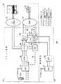
図1〜図6は、本発明の一態様に従って構築された協働的な無線ネットワーク100の好ましい実施形態を示すブロック図である。
【0020】
本出願は、通信システムに関する。通信分野では、情報または信号を伝達する設備、構造、または方法の実施に、各種の信号リード、バス、データパス、データ構造、チャネル、バッファ、および他の通信パスを使用することができ、これらはしばしば機能的に同等であることが分かろう。したがって、別記しない限り、信号または情報を伝達する装置またはデータ構造への言及は、概して機能的に同等の装置およびデータ構造すべてを言及するものである。
【0021】
図1〜図6に最も良く示すように、要素間の接続はリンクまたはパスと呼ばれ、実線や波線で示されている。このような線はそれに適用される参照番号があるものとないものがあり、またさらに、それに適用される単一ハッシュマーク、二重ハッシュマーク、点や「X」等の特徴印が付いているものもある。参照番号または他の印がない線の接続は、制御またはベアラトラヒックの搬送に利用できるリンクを表し、このリンクは図に示される特定の状況において使用される場合とされない場合がある。特徴印が付加されていない実線は、ベアラ情報を搬送するリンクを表す。特徴印が付加されていない波線は、制御情報を搬送するリンクを表す。参照番号や上記特徴印(以下、「パス」と呼ぶ)の付いた線の接続は、図に示す特定の状況において、利用できるリンクのうち実際に用いられるリンクを識別するためのオーバーレイとして提供されている。したがって、該パスは、追加リンクを示すものではなく、利用可能なリンクを用いるか否か、および利用可能なリンクをどのように用いるかを示す。
【0022】
図1〜図6は、ネットワーク100の構造的編成を示す他、本発明に従って構築された通信システムの好ましい実施形態においてサポートされるいくつかの異なるハンドオーバ状況前後の制御およびベアラパスの初期および最終の構成をさらに示す。単一ハッシュマークの付いたパスは、ハンドオーバ前のベアラパスの初期構成を示す。二重ハッシュマークの付いたパスは、ハンドオーバ後のベアラパスの最終構成を示す。点の付いたパスは、ハンドオーバ前の制御パスの初期構成を示す。「X」の付いたパスは、ハンドオーバ後の制御パスの最終構成を示す。
【0023】
図1に最も良く示すように、ネットワーク100は、互いにシステム間動作用に構成され、かつまた適切なランドサイドネットワークと網間接続するよう構成された、パケット無線通信システム100と、回線無線通信システム120と、を備えることが好ましい。本明細書で用いる「ランドサイドネットワーク」という語は、他の無線ネットワークおよび通過ネットワークを含むがこれらに限定されない、ランドサイドネットワークと同等のインタフェースを提供する他のあらゆるネットワークの包含を意図する。例えば、パケット無線システム110は、図1において、一般に回線ネットワークとして特徴付けうる公衆交換電話網(PSTN)132と、一般にパケットネットワークとして特徴付けうるパケットデータネットワーク136と、に接続されて示されている。図3および図4に最も良く示すように、回線無線システム120は、外部ネットワーク132にも接続しうる。ネットワーク132および136は実際に、各種の回線および/またはパケット技術の伝送要素および交換要素を採用しうるが、ネットワークは、本明細書において、他のネットワークおよびシステムに、そして特に各ネットワークが採用する呼モデルに提示するインタフェースに従って特徴付けられる。
【0024】
本明細書において、「呼」という語は、通信システムまたはネットワークを介した端末セット間での情報転送セッションを指し、古典的な回線音声呼、パケット音声呼、回線データ呼、無接続呼、またはパケットデータ呼、およびそのマルチメディアバリアントを含むものであるが、これらに限定されない。この適用は2つの端末が関与する呼を指すが、当業者は、本発明の精神を踏まえて、多数共同呼をサポートするよう例示的な実施形態を変更する方法を理解するであろう。
【0025】
当分野で知られているように、ネットワーク110は、IETF RFC−2543(セッション開始プロトコル(SIP))およびITU規格H.323に規定されているものを含む適切なパケットプロトコルを用いて、パケットランドサイドネットワーク136(以下、「PDN」と呼ぶ)とインタフェースすることができる。他のプロトコルおよび規格を用いることも可能である。ネットワーク110は、当分野で一般にITU−T信号方式No7として知られている回線プロトコルを用いて、回線ランドサイドネットワーク132とインタフェースすることができる。さらに説明するように、パケット無線ネットワーク110は、パケット無線ネットワークで必要とされるフォーマットおよび呼モデルと、回線ランドサイドネットワーク132(以下、「PSTN」と呼ぶ)で必要とされるフォーマットおよび呼モデルとの間でベアラおよび制御情報を変換するために、適切なゲートウェイ設備150および154を備えることが好ましい。
【0026】
ネットワーク100の例示的な一実施形態を、単一のパケット無線システム110および単一の回線無線システム120とを含むものとして図示しているが、当業者は、商業的に開発された実施形態がそれぞれのタイプの無線システムを複数組み込みうることを理解するであろう。同様に、ネットワーク100の例示的な実施形態は、2つのランドサイドネットワーク、すなわちPSTN132およびPDN136に接続されて図示されているが、商業的に開発される実施形態はいくつかのかかるネットワークに接続されうることが理解されるであろう。最も商業的な無線システムは、他の無線システム、および外部ネットワーク、公衆網、またはランドサイドネットワークへインタフェースするため、複数の接続ポイントを組み込む。
【0027】
回線無線システム120は、任意適切な無線通信システムであることが好ましい。例えば、システム120は、AMPS、GSM、TDMA、またはCDMAとして一般に知られている(しかし、これらに限定されない)無線システムタイプのいずれでもよく、上記システムタイプの振る舞いは、周知の業界、政府、または政府間の規格本体によって規定される。さらに、システム120は、好ましくは、他の無線システムとの相互動作に適切に定義されたインタフェースを提供する。例えば、システム120は、米国規格協会刊行のANSI−TIA/EIA41−D:Cellular Radiotelecommunications Intersystem Operations、欧州電気通信標準化機構(ETSI)刊行のGSM09.02 Mobile Application Part (MAP)プロトコルとして知られるプロトコル、および他の適したプロトコルである標準化されたシステム間動作プロトコルを実施しうる。
【0028】
図1〜図6に最も良く示すように、回線システム120は、少なくとも1つのモバイル交換センタ(MSC)124への制御接続およびベアラ接続を有する、少なくとも1つの基地局システム(BSS)122を含むことが好ましい。図3および図4に最も良く示されるように(しかし、明確にするため、その他の図では図示せず)、MSC124は、ランドサイドネットワークPSTN132への制御接続およびベアラ接続を有する。MSC124は、網間接続ゲートウェイを介してPDN136への制御接続およびベアラ接続(図示せず)も有することができる。呼が網間接続ゲートウェイを介してPDN136で終端する場合、網間接続ゲートウェイは、PDN136のパケット性質をマスクすることで、回線システム120は、その呼を、PSTN132で終端する呼と同様にして取り扱う。MSC124は、好ましくは、パケットネットワーク110のメディアゲートウェイ要素150(より詳細に後述する)への制御接続およびベアラ接続を有する。簡略化のため、単一のBSSおよび単一のMSCのみを図示している。しかし、商業的な実施形態では、システム120は、MSCに接続された多数のBSSを組み込む可能性が高く、またいくつかのMSCを組み込みうる。システム120は、本発明の理解には必ずしも必要ではなく、明確性を強めるため省略する他の要素を含みうる。
【0029】
パケット無線システム110は、既知のパケット無線ネットワークと概して同様にして構築することができるが、本発明の一態様による相互動作可能なハンドオーバ機能を提供するように、特定のコンポーネントを追加すると共に、他のコンポーネントを変更している。これについてはさらに後述する。例えば、システム110は、汎用パケット無線サービス(GPRS)の基本構造および機能性を、さらに後述する適宜変更を行った状態で採用することができる。GPRSは、欧州電気通信標準化機構GSM規格02.60、03.60、および04.60と、第三世代パートナーシッププロジェクト(3GPP)技術仕様書3GPP TS23.060を含む規格文書の拡張シリーズに記載されているパケット無線通信システムである。パケット無線システム110の以下の説明ではGPRSの用語を用いるが、部分的に、RFC2002、2003、2004、2005、2006、および2344に規定されているモバイルIPシステムの実施である(インターネット技術標準化委員会(IETF:Internet Engineering Task Force)刊行)、ANSI規格IS−835に規定されているCDMAパケットシステムを含むがこれに限定されない、他のパケット無線システムを採用することも可能である。
【0030】
図1〜図6に最も良く示すように、システム110は、好ましくは、基地局システム(BSS)142、サービングGPRSサポートノード(SGSN)146、ゲートウェイGPRSサポートノード(GGSN)148、メディアゲートウェイ(MG)150、呼状態制御機能(CSCF)152、およびメディアゲートウェイ制御機能(MGCF/T−SGW)154を含む。BSS142は、適した無線ユーザ端末140a〜140f(図1〜図6のハンドオーバ状況のうちの特定の1つに関係のない一般的な文脈で参照する場合には、140)を用いた無線通信向けに適合されている。BSS142は、SGSN146への制御接続およびベアラ接続を有する。SGSN146は、GGSN148への制御接続およびベアラ接続を有する。GGSNは、MG150への制御接続およびベアラ接続を有する。GGSN148はまた、ランドサイドネットワークPDN136への制御接続およびベアラ接続も有し、また他のネットワーク(図示せず)へのこのような接続を有する場合もある。MGは、ランドサイドネットワークPSTN132へのベアラ接続を有し、また他のネットワーク(図示せず)へのこのような接続を有する場合もある。GGSN148はまた、CSCF152への制御接続も有する。MG150は、MGCF/T−SGW154への制御接続をさらに有する。CSCF152は、MGCF/T−SGW152への制御接続をさらに有する。MGCF/T−SGW152は、PSTN132への制御接続を有する。
【0031】
一般的に、BSS142、SGSN146、およびGGSN148は、これらがGPRSシステムで通常実行する機能と同等の機能を実行する。しかし、パケット無線システム110は、PSTN132等の回線ランドサイドネットワークと、そしてシステム120等の回線無線システムとも相互動作しなければならない。回線システムで用いられる呼モデル、制御情報のフォーマット、およびベアラコンテンツのフォーマットは、パケットシステムで用いられるものとは異なるため、パケットネットワーク110は、パケットネットワークに固有のベアラコンテンツまたは制御メッセージフォーマットを用いて回線ネットワークと直接通信することはできない。したがって、MG150が、パケットネットワーク110で用いられる形式と、PSTN132および回線ネットワーク120で用いられる形式との間でベアラコンテンツを変換する機能を実行する。MGCF/T−SGW154はMG150を制御する。MGCF/T−SGW154およびCSCF152は協働して、パケットネットワーク110で用いられる形式とPSTN132および回線無線ネットワーク120で用いられる形式との間で、呼モデルおよび呼処理に関連する制御情報を変換する。
【0032】
さらに、MGCF/T−SGW154およびCSCF152はさらに協働して、回線無線ネットワークのモバイル交換センタ(MSC)のハンドオーバ機能およびアンカーモバイル交換センタ(アンカーMSC)特徴制御機能をエミュレートし、それによってパケットネットワークが単に別の回線ネットワークであるかのように、パケットネットワーク110が回線ネットワーク120と相互動作することが可能である。パケットシステム110においてエミュレートされるアンカーMSCに必要な機能性は、回線システム120においてMSCに求められる完全な機能性よりも少ない。特に、エミュレートされたアンカーMSCはシステム間でのハンドオーバを管理しなければならないが、無線資源を管理する必要はない。これは、パケットシステム110において、無線資源は、中央MSCではなくBSS142によって管理されるためである。エミュレートされたアンカーMSCの機能性は主にCSCF152およびMGCF/T−SGW154にあり、好ましくは、回線システム120のMSC124に対して、ハンドオフ要求を送信する能力、またはハンドオフ関連情報を返信する能力を含む。
【0033】
システム間ハンドオーバのサポートに必要な各種機能は、パケットシステム110の実施に用いられる特定のアーキテクチャに適するように割り当てることができる。本発明に従って構築されるパケットシステム110の好ましい実施形態において、該割り当ては次のようなものでありうる。MG150は、無線パケットシステム110と、回線システム120あるいは回線ランドサイドネットワークPSTN132のいずれかとの両者に関連する任意の呼について、ベアラ情報の必要なすべての変換を行う。MGCF/T−SGW154は、パケットシステム110と、回線システム120あるいは回線ランドサイドネットワークPSTNのいずれかとの間でのシグナリングプロトコルの変換を行う。MGCF/T−SGW154もまた、ベアラフォーマット間の変換をいつ行うか、どの変換を行うかについてのMGへの命令、および使用すべき特定の設備の識別を含む、適切な制御メッセージを介してMG150を制御する。CSCF152は、ハンドオーバ中に回線MSCが認識するものと予期される呼モデルを実施する。
【0034】
有利なことに、この方法で、パケットネットワーク110との相互動作をするために、回線システム120に必要な変更またはアップグレードは、最小かまたはゼロである。回線システム120が、いずれのユーザ端末140がパケット可能かを識別し、かかる端末のパケットシステム110へのハンドオーバのみを試行することが有利な場合もある。大部分の従来の回線システム120は、ユーザ端末の中から、特定の他システムと呼を網間接続する性能を有するものを区別する性能を含む。例えば、ユーザ端末によっては、それぞれが動作可能なシステムを識別する「クラスマーク」を伝送するものがある。無線システムによっては、同様にユーザ端末140が動作可能なシステムを識別することのできる特定のプロファイル情報について、ユーザのホームシステムと交渉するよう構成されるものがある。したがって、回線システム120に対するパケット可能なユーザ端末140の識別には、システム120が用いるパラメータの現在確保されている値を定義し、他の回線システムとの呼の網間接続性能の現在の性能を実施することを含みうる。それにもかかわらず、回線システムおよびそのクラスマークまたはプロファイル情報の解釈に関連する規格の変更が有利なこともある。あるいは、「モバイル支援ハンドオーバ」を用いていずれのセルがハンドオーバターゲットであるかを決定する場合、ユーザ端末は、互換性のあるセルのみを報告することが好ましい。これにより、回線システムや関連規格への変更が不要になる。
【0035】
上述したように、パケット無線システム110は、ANSI規格IS−835に規定されているCDMAパケットシステムの技術を用いても実施することができる。この場合、BSS140の機能は、CDMAパケットシステムの無線基地局装置(BTS)によって行われ、SGSN146およびGGSN148の機能はCDMAパケットシステムのホームエージェントおよびパケットデータサービングノード(PDSN)によって行われる。
【0036】
図1〜図6は、ネットワーク100における4つの異なるハンドオーバ状況についての制御パスおよびベアラパスの初期構成および最終構成を示す。図7〜図9は、図1〜図6のネットワーク100と組み合わせて、かつ本発明の態様に併せて用いる、ハンドオーバを行う方法のステップを示す流れ図である。各ハンドオーバ状況について、初期および最終の信号パス構成を示す図と、対応するハンドオーバ方法を示す図と併せて説明する。
【0037】
図1、図2、および図7は、ランドサイド終端がPSTN132等の回線ネットワークを通る、パケットシステム110から回線システム120への呼のハンドオーバを対象としている。したがって、このハンドオーバ状況は、パケット無線システム110および回線ランドサイドネットワークPSTN132を通して、無線加入者端末140aとランドサイド加入者端末134の間で安定した呼が確立される場合を考える。この状況では、かつ本明細書において考察する他のすべての状況では、呼の発信が無線端末140からであるか、またはランドサイド端末134、138からであるかは問題ではない。さらに、本明細書において考察するすべてのハンドオーバ状況について、端末は図において特定のメディアまたはコンテンツを備えて図示されている(例えば、端末140aは音声ハンドセットとして図示され、端末134は通常の音声電話機として図示されている)かもしれないが、これらの端末はいずれも、音声、ビデオ、ファクシミリ等を含むがこれらに限定されない、無線システムおよびランドサイドネットワークによってサポートされるあらゆるメディアまたはコンテンツタイプを備えることができる。
【0038】
本発明は呼の初期セットアップを対象とするものではないが、以下のステップは、無線端末140aからランドサイド端末134への例示的な呼の確立プロセスを理解する際の予備知識として役立つであろう。
(a)端末140aがパケットシステム110に登録し、CSCF152を「発見」する(すなわち、CSCF152に気付く)。
(b)端末140aが、セッション開始プロトコル、H.323、または別の適したパケット呼セットアッププロトコルを用いて、たまたま回線ネットワークPSTN132に存在するランドサイド端末134への呼を要求するメッセージをCSCF152に送信する。
(c)被呼エンドポイントが回線ネットワークPSTN132にあるため、パケットセッションがMG150に向かうことを示す制御メッセージを、CSCF152がGGSN148に送信する。
(d)MGCF/T−SGW154が、制御メッセージをMG150に送信して、パケット呼の終端を受信するよう命令し、ベアラコンテンツを64kbpsPCMから、または64kbpsPCMに変換しなければならず、またPCMストリームをトランクで回線ネットワークPSTN132に、または回線ネットワークPSTN132から伝送すべきであると指定する。
(e)MGCF/T−SGW154が、パケット呼モデル機能を回線ネットワークPSTN132に適したシグナリング(例えば、ITU−T No7シグナリングメッセージ)に変換し、上記シグナリングをPSTN132に送信する。
(f)MG150が、パケットシステム110と回線ランドサイドネットワークPSTN132の間で双方向的にベアラトラヒックを変換する。
【0039】
上記プロセスの結果、端末140aと端末134の間に安定した呼が確立され、これを図1に示す。図1に最も良く示すように、端末140aとCSCF152の間には制御パス170が存在する。CSCF152とGGSN148の間には追加の制御パス172が延び、CSCF152とMGCF/T−SGW154の間にはさらなる制御パス174が延びる。MGCF/T−SGW154とMG150の間には制御パス176が延びる。上記制御パスはすべてパケットである。さらに、MGCF/T−SGW154とPSTN132の間には回線制御パス178が延び、MGCF/T−SGW154が呼セットアップおよび他のシグナリングを回線ネットワークと交換できるようにする。端末140aとMG150の間にはパケットベアラパス180が延びる。MG150とPSTN132の間には回線ベアラパス182が延びる。MG150はボコーダとして機能し、パケット無線システムと回線ランドサイドネットワークPSTN132の間でベアラトラヒックを変換する。
【0040】
図7は、図1の協働的な無線ネットワーク100と併せて用いる、無線端末140とランドサイド回線端末134の間での呼の場合に、パケットシステム110から回線システム120にハンドオーバを行う、本発明の一態様による方法700を示す流れ図である。上記方法は、ステップ710から始まり、ここで、システム110がハンドオーバが必要であり、許容可能なハンドオーバターゲットが回線システム120内の基地局122であると決定する。上記決定は、例えば、パケットシステム110のBSS142によって行い、CSCF152に報告することができる。いつハンドオーバが要求されるか、いくつかの潜在的なハンドオーバターゲットのいずれが最適かを決定するための様々な技術が当分野で良く知られている。異なる無線システム技術は、この問題に対して別のアプローチを採用している。例えば、端末と基地局間の現在のRFパスの質が良くないため、負荷平衡や隣接セル間での最適化を達成するため、または他の管理的理由や方針的理由から、ハンドオーバが望ましい。適切なハンドオーバターゲットを選択する方法には、無線端末の信号強度測定値についての付近の基地局のポーリングと、無線端末が付近の基地局からの伝送の信号強度の測定値を報告するいわゆる「モバイル支援ハンドオーバ」とが含まれる。本発明に関して、システム110および120の無線システム技術に適したあらゆるハンドオーバ決定技術を用いることができる。
【0041】
ステップ712において、CSCF152が、ハンドオーバターゲットが回線無線システム120にあり、したがって、システム120との通信時には、CSCF152、MG150、およびMGCF/T−SGW154が協働してアンカーMSCをエミュレートしなければならないことを認識する。ステップ714において、CSCF152およびMGCF/T−SGW154が協働し、MSC124と適切なハンドオーバメッセージシーケンスの交換をフォーマットし開始することで、システム120とのハンドオーバを交渉する。システム120がANSI−41システム間動作プロトコルを用いている場合、適切なメッセージシーケンスは、(a)ターゲットセルにおけるトラヒックチャネルを要求する、MGCF/T−SGW154から回線システム120のMSC124への、設備指示呼び出し(Facilities Directive Invoke)、(b)無線資源の確保を確認し、かかる資源を識別する(例えば、承認されたトラヒックチャネルの識別)、MSC124からMGCF/T−SGW154への、設備指示対話(Facilities Directive Conversation)、(c)無線端末のハンドオーバが成功したことを通知する、MSC124からMGCF/T−SGW154へのチャネル上モバイル指示(Mobile on Channel Indication)、である。ステップ716において、システム120が呼処理に用いる無線資源を割り当て、システム110にかかる資源の識別を通知する。回線システム120が、BSS122、MSC124、MG150を通して呼のためのパス280を確立する。呼はパケットシステム110内で発信されたため、そのシステムはアンカーMSCをエミュレートしなければならず、また、呼は依然としてパケットシステムを通してルーティングされる状態でなければならない。したがって、呼がベアラパス282を介して、MSC124とMG150の間に延びる。
【0042】
ステップ718において、パケットシステム110からの指示のもとで、無線端末が割り当てられたターゲットトラヒックチャネルの使用を開始する。ステップ720において、MSC124がMGCF/T−SGW154およびCSCF152に、無線端末140b(図2参照)が首尾良く回線システム120にハンドオーバされたことを通知する。ステップ722において、パケットシステム110において呼が用いた資源が解放される。MG150とPSTN132の間のベアラパス182は使用され続ける。実施によっては、無線システムに必要なボコードがMSC124で行われるものもあり、MG150で行われるものもある。MG150でのボコードが、ネットワーク資源を温存するという点において、好ましい。MG150は、ボコード/フォーマットを変換する必要性に対処する他、回線MSCによって通常提供される特定の機能を提供するように、交換ファブリックおよび他の設備を組み込むこともできる。しかし、MG150は、従来の回線技術以外の技術を用いて、ファブリックを実施し、機能を提供することも可能である。上記方法は、ステップ724において終了する。
【0043】
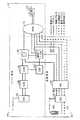
図2は、パケットシステム110から回線システム120へのハンドオーバが首尾良く完了したときの制御パスおよびベアラパスの最終構成を示すブロック図である。ベアラパス280は、無線端末140bからBSS122、そしてMSC124を通って延びる。ベアラパス282は、MSC124からパケットシステム110のMG150にさらに延びる。呼をパケットネットワーク内で搬送したときに、上記呼を搬送するために以前用いたMG150とPSTN132の間のベアラパス182は、依然として使用中の状態である。制御パス270が無線端末140bからMSC124に延びる。制御パス272がMSC124からパケット無線システム110のMGCF/T−SGW154に延びる。MGCF/T−SGW154からMG150に延びていた制御パス176はその場所に残り、MGCF/T−SGW154からCSCF152に延びるシグナリング制御パス172も同様である。MGCF/T−SGW154からのPSTN132への回線シグナリング制御パスもその場所に残る。したがって、CSCF152、MGCF/T−SGW154、およびMG150が協働して、現在では回線システム120が広く処理している呼に対して、アンカーMSCの機能を行う。
【0044】
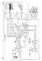
図3および図4は、ランドサイド終端がPSTN132等の回線ネットワークを通る、回線システム120からパケットシステム110への呼のハンドオーバを対象とする。したがって、このハンドオーバ状況は、回線無線システム120および回線ランドサイドネットワークPSTN132を通して、無線加入者端末140cとランドサイド加入者端末134の間で安定した呼が確立される場合を考える。
【0045】
ハンドオーバを行うために、安定した呼を無線端末140cからランドサイド端末134に確立しなければならない。その構成は、図3において最も良く見て取れる。端末140cとMSC124の間には制御パス370が存在する。MSC124とPSTN132の間には追加の制御パス372が延びる。上述した制御パスはすべて回線である。端末140cとMSC124の間には回線ベアラパス380が延びる。MSC124とPSTN132の間には回線ベアラパス382が延びる。
【0046】
図8は、図3の協働的な無線ネットワーク100と併せて用いる、無線端末140とランドサイド回線端末134の間での呼の場合に、回線システム120からパケットシステム110にハンドオーバを行う、本発明の一態様による方法800を示す流れ図である。上記方法は、ステップ810から始まり、ここで、回線システム120が、ハンドオーバが必要であり、許容可能なハンドオーバターゲットがシステム110内の基地局142であることを決定する。ステップ710に関連するハンドオーバ決定の説明も参照されたい。ステップ812において、MSC124が、ハンドオーバターゲットがシステム110内にあると決定する。回線システム120は、必ずしもシステム110がパケットシステムであることに気付く必要はない。
【0047】
ステップ814において、回線システム120が、制御パス480(図4)を介してMGCF/T−SGW154と交換するメッセージシーケンスをフォーマットし、これを開始することで、ハンドオーバへの関心を示す。上記メッセージシーケンスは、サービングMSC124か、呼に存在する場合にはアンカーMSC(図示せず)によって交換しうる。MSCは、回線MSCにハンドオーバする場合と同じプロトコルおよび手順を採用することができる。システム120が、ANSI−41システム間動作プロトコルを用いている場合、ハンドオーバ交渉は、ステップ714に関して説明したメッセージシーケンスを、方向を逆にして(すなわち、回線システムからパケットシステムに)採用することができる。メッセージシーケンスは、MGCF/T−SGW154で受信され、それに関連する情報がCSCF152に送信される。ステップ816において、パケットシステム110が呼処理に用いる無線資源を割り当て、回線システム120に通知する。パケットシステム110は、BSS142からMG150を通して呼についてのパス490を確立する。呼は回線システム120内で発信されたため、パケットシステム110は回線MSCをエミュレートしなければならず、また、呼は依然として回線システムのMSC124を通してルーティングされる状態でなければならない。ステップ818において、回線システム120が、無線端末140に、パケットシステム110の割り当てられたトラヒックチャネル(または同等の資源)の使用を開始するよう命令する。
【0048】
ステップ820において、CSCF152が、呼および無線端末140dの識別に気付く。CSCFは、パケット呼モデルをインスタンス化する。ステップ822において、パケットシステムは、MG150への呼についてのベアラパス490を確立する。このステップの結果、パケットセッションが無線端末140dからMG150に確立される。呼は、ベアラパス492に沿って回線無線システム120のMSC124(または、もし存在すれば別のアンカーMSC)に延びる。アンカーMSCが呼の制御を維持するという要件により、呼のレッグ(leg)に面するランドサイドネットワークは回線システム120に残る。
【0049】
ハンドオーバに続き、ユーザが要求する特徴の提供(回線システム120において利用可能な程度まで)は、回線システム120のMSC124(または、もし存在すれば別のアンカーMSC)によって管理され続ける。ステップ824において、サービングMSCが、MG150、MSC124、およびPSTN132の間の接続のサポートに必要とされない程度まで、以前その呼に割り当てられていた資源を解放する。上記方法はステップ826において終了する。
【0050】
図4は、回線システム120からパケットシステム110へのハンドオーバが首尾良く完了したときの制御パスおよびベアラパスの最終構成を示すブロック図である。ベアラパス490は、無線端末140dからBSS142を通ってMG150に延びる。ベアラパス492は、MG150からMSC124にさらに延び、よってパケットシステム110が呼を回線システム120のアンカーMSCにルーティングできるようにする。回線ネットワーク内で搬送されていた呼の搬送に先に使用した、MSC124とPSTN132の間のベアラパス382は、依然として使用中の状態である。
【0051】
制御パス470が、無線端末140dからGGSN148に、そしてMG150に延びる。追加の制御パス472、474がGGSN148からCSCF152に延びる。MG150からMGCF/T−SGW154には制御パス478が延びる。制御パス476がCSCFとMGCF/T−SGWをリンクする。上記制御パスはすべてパケットパスである。例えば、ITU−T信号方式No7リンクとして実施される回線制御パス480がMGCF/T−SGW154から回線無線システム120のMSC124の間に延びる。MSC124からPSTN132に延びていた回線制御パス372はその場所に残る。したがって、MSC124(または、もし存在すれば別のアンカーMSC)は、パケットネットワーク110によって広く取り扱われる呼のアンカーMSCとして機能する。
【0052】
図5、図6、および図9は、ランドサイド終端がPDN136等のパケットネットワークを通る、パケットシステム110から回線システム120への呼のハンドオーバを対象としている。したがって、このハンドオーバ状況は、回線無線システム120およびパケットランドサイドネットワークPDN136を通して、無線加入者端末140eとランドサイド加入者端末138の間で安定した呼が確立される場合を考える。
【0053】
ハンドオーバを行うために、安定した呼を無線端末140eからランドサイド端末138に確立しなければならない。その構成は、図5において最も良く見て取れる。端末140eとCSCF152の間には制御パス570が存在する。CSCF152とGGSN148の間には追加の制御パス572が延びる。GGSN148とパケットランドサイドネットワークPDN136の間にはさらなる制御パス574が延びる。上記制御パスはすべてパケットである。端末140eとGGSN148の間にはパケットベアラパス580が延びる。GGSN148とパケットランドサイドネットワークPDN136の間にはパケットベアラパス582が延びる。
【0054】
図9は、図5の協働的な無線ネットワーク100と併せて用いる、無線端末140とランドサイドパケット端末138の間での呼の場合に、パケットシステム110から回線システム120にハンドオーバを行う、本発明の一態様による方法900を示す流れ図である。上記方法は、ステップ910から始まり、ここで、パケットシステム110がハンドオーバが必要であり、許容可能なハンドオーバターゲットが回線システム120内の基地局122であると決定する。ステップ710に関連するハンドオーバ決定の説明も参照されたい。この決定は、例えば、BSS142によって行い、CSCF152に報告することができる。ステップ912において、ハンドオーバターゲットが回線無線システム120にあることをCSCF152が認識する。
【0055】
ステップ914において、CSCF152およびMGCF/T−SGW154がMG150にベアラパス682および684を確立して、呼を回線システム120のMSC124に搬送すると共に、必要なベアラコンテンツの変換を行うよう命令する。ステップ916において、MGCF/T−SGW154が、システム120との適切なハンドオーバメッセージシーケンスの交換をフォーマットし開始することで、システム120とのハンドオーバを交渉する。システム120がANSI−41システム間動作プロトコルを用いている場合、ハンドオーバ交渉は、ステップ714と共に説明したメッセージシーケンスを採用しうる。ステップ918において、パケットシステム110が、回線システム120の、割り当てられたトラヒックチャネルの使用を開始するよう無線端末に命令する。無線端末は上記命令を実行する。ステップ920において、MSC124がMGCF/T−SGW154に、無線端末140f(図6参照)が回線システム120に首尾良くハンドオーバされたことを通知する。ステップ922において、回線ネットワークのMSC124と、ランドサイドネットワークPDN136間の接続のサポートに必要ない程度まで、パケットシステム110において呼が用いた資源を解放する。GGSN148とPDN136の間のベアラパス582は、依然として使用中の状態である。上記方法はステップ924において終了する。
【0056】
図6は、パケットシステム110から回線システム120へのハンドオーバが首尾良く完了したときの制御パスおよびベアラパスの最終構成を示すブロック図である。ベアラパス680が、無線端末140fからBSS122を通してMSC124に延びる。さらに、ベアラパス682がMSC124からパケットシステム110のMG150に延びる。ベアラパス684がさらにMG150からGGSN148に延びる。呼をパケットネットワーク内で搬送したときに、上記呼を搬送するために以前用いたGGSN148とPDN136の間のベアラパス582は、依然として使用中の状態である。制御パス670が無線端末140fからMSC124に延びる。制御パス672がMSC124からパケット無線システム110のMGCF/T−SGW154に延びる。さらなる制御パス674、676、および678がそれぞれ、MG150をMGCF/T−SGW154に、MGCF/T−SGW154をCSCF152に、そしてCSCF152をGGSN148にリンクする。GGSN148からPDN136へのパケットシグナリング制御パス574は、その場所に残る。したがって、MGCF/T−SGW154およびMG150が協働して、現在では回線システム120が広く処理している呼に対して、アンカーMSCの機能を行う。
【0057】
本明細書では、パケット無線システム110および回線無線システム120を別個の無線システムとして説明すると共に、各システムが、簡略化のため、他方のシステムの実施に用いられる要素とは異なる要素を用いて実施されるものとして添付図面に示されているが、実施形態によっては、無線システム110および120が実際に共通の要素およびコンポーネントを用いて実施される場合もあることが分かろう。したがって、実際の実施として、単一のコンポーネントまたは要素が、無線システム110および120双方の選択された機能を行う場合もあり、複数のコンポーネント、要素、および機能を単一ユニットに統合する場合もある。限定ではなく例として、単一の基地局システム(共有される制御要素および無線要素を備えうる)は、パケットBSS142および回線BSS122の双方の機能を実行する場合もあり、その基地局システムは、SGSN146およびMSC124双方への接続を有する。同様に、単一ユニットがパケットSGSN146、GGSN148、CSCF152、MGCF/T−SGW154、および回線MSC124の機能を実行することも可能である。このような場合、かつ特に各種コンポーネントが同じベンダーによって提供される場合、これらのシステム間で用いられるシステム間相互動作プロトコルは、ANSI−41等の標準プロトコルではなく、ベンダーが規定するメッセージプロトコルの形態をとりうる。しかし、依然として、上述したパケット呼モデルおよび回線呼モデルの双方を実施し、その間でハンドオーバを行う必要がある。
【0058】
本出願は、マルチメディア通信システムを含めた通信システムに関する。上記通信システムは、アナログ電子システム、デジタル電子システム、マイクロプロセッサ、および他の処理要素と、かかるシステムおよび処理要素と組み合わせて方法、プロセス、または方針を実施するソフトウェアおよび他の具体化されるステップ、命令等の集まりとを含むがこれらに限定されない様々な電子技術および光技術を用いて実施することができる。本明細書に記載した実施形態は例示的なものである。したがって、実施形態を特定の技術に関して説明したが、本発明の精神を踏まえて、システムの実施に他の同等の技術も使用しうることが分かろう。
【0059】
本発明の態様によれば、既存の回線無線システムとパケットシステム間でのシステム間ハンドオフを提供する改良された無線ネットワークおよび関連する方法が開示される。パケット無線システムは、有利なことに、回線呼モデルおよびパケット呼モデルの間で変換を行うと共に、回線システムおよびパケットシステムが要求するフォーマット間でのベアラトラヒックの変換を行う。メディアゲートウェイコンポーネントは、各システムで用いられるフォーマット間でベアラトラヒックの変換を行う。メディアゲートウェイ、メディアゲートウェイ制御機能、および関連する呼状態制御機能が協働して回線無線システムの振る舞いをエミュレートするため、従来の回線システムに組み込まれた場合に、パケットシステムが別の回線無線システムのように見える。必要であれば、メディアゲートウェイ、メディアゲートウェイ制御機能、および呼状態制御機能はさらに協働して、回線無線システムのアンカーMSCの機能をエミュレートする。上記改良されたネットワークおよび方法により、従来の無線システムへの変更を最小限に抑えるか、回避しながら、回線システムとパケットシステムの間でハンドオーバを行うことができる。
【0060】
本発明の上記実施形態は単に、本発明を実行しうる方法の一例にすぎない。他の方法も可能であり、他の方法は本発明を定義する添付の特許請求の範囲内にある。
【図面の簡単な説明】
【図1】システム間動作向けに構成されたパケット無線システムおよび回線無線システムを含む、本発明の一態様に従って構築された協働的な無線ネットワーク100を示すブロック図であり、無線端末とランドサイド回線端末間の呼の場合での、パケットシステムから回線システムへのハンドオーバ前の制御およびベアラ信号パスの初期構成をさらに示している。
【図2】図1の協働的な無線ネットワーク100のブロック図であり、図1の呼の場合での、パケットシステムから回線システムへのハンドオーバの結果における制御およびベアラ信号パスの最終構成を示している。
【図3】図1の協働的な無線ネットワーク100のブロック図であり、無線端末とランドサイド回線端末間の呼の場合での、回線システムからパケットシステムへのハンドオーバ前の制御およびベアラ信号パスの初期構成を示している。
【図4】図1の協働的な無線ネットワーク100のブロック図であり、図3の呼の場合での、回線システムからパケットシステムへのハンドオーバの結果における制御およびベアラ信号パスの最終構成を示している。
【図5】図1の協働的な無線ネットワーク100のブロック図であり、無線端末とランドサイドパケット端末間の呼の場合での、パケットシステムから回線システムへのハンドオーバ前の制御およびベアラ信号パスの初期構成を示している。
【図6】図1の協働的な無線ネットワーク100のブロック図であり、図5の呼の場合での、パケットシステムから回線システムへのハンドオーバの結果における制御およびベアラ信号パスの最終構成を示している。
【図7】無線端末とランドサイド回線端末間での呼の場合に、パケットシステムから回線システムへのハンドオーバを行う、図1に示す協働的な無線ネットワーク100と組み合わせて用いる本発明の一態様による方法を示す流れ図である。
【図8】無線端末とランドサイド回線端末間での呼の場合に、回線システムからパケットシステムへのハンドオーバを行う、図1に示す協働的な無線ネットワーク100と組み合わせて用いる本発明の一態様による方法を示す流れ図である。
【図9】無線端末とランドサイドパケット端末間での呼の場合に、パケットシステムから回線システムへのハンドオーバを行う、図1に示す協働的な無線ネットワーク100と組み合わせて用いる本発明の一態様による方法を示す流れ図である。[0001]
BACKGROUND OF THE INVENTION
The present invention relates to communication systems, and more particularly to systems and methods for supporting wireless call handover between wireless communication systems and components thereof that support different call models, including line and packet call models.
[0002]
[Prior art]
Because an important feature of many wireless communication systems is mobility, users involved in calls are supported by a second set of wireless infrastructure equipment from a first location supported by the first set of wireless infrastructure equipment. The call can be moved to the second location without much interruption. Many early wireless communication systems were developed to provide mobile phone services. Early cell phone systems typically employed a single radio base station with limited capacity but arranged to cover a large geographic area. The mobile user can move widely within the coverage area and expect the call to be maintained under the condition that the user does not move to a location where the radio frequency path to the base station is unavailable I was able to. When cellular cellular telephone systems with multiple radio base stations each serving a much smaller adjacent area, or “cell”, were developed, the user involved in the call would be able to cover the system without interrupting the call. It was extremely important to be able to move from cell to cell through the area.
[0003]
Functions and implementations that allow a second radio base station to service a stable call currently served by the first radio base station (or another similar element of a radio system that provides a radio interface) The process is called “handoff” or “handover”. Initially, handover was provided between single system and similar technology cells. However, a standard protocol has been developed that allows handover between cells of different systems and allows handover between cells and / or systems of different technologies. For example, a standard protocol allows a user to maintain a call as it crosses the boundary from one radio system to another radio system, possibly with different entities operating and using different types or brands of infrastructure equipment. become. For example, this type of protocol includes ANSI-TIA / EIA41-D published by the American National Standards Institute, a standard intersystem operating protocol known as Cellular Radiotelecommunications Intersystem Operations, and GSM09.02 Mobile published by the European Telecommunications Standards Institute (ETSI). There is an Application Part (MAP) protocol. Furthermore, standard protocols have also been developed to allow handover between systems / cells of different (but collaborative) air interface technologies that use the same call model. For example, a subscriber's handset and system infrastructure equipment performs a call handover from a cell employing a digital transmission technology such as CDMA or TDMA to a cell employing an analog transmission technology such as AMPS. be able to. The performance of performing handover between the GSM system and the UMTS system has also been described. Historically, the need for mobility has been a motivation for using handover, but handover can improve load reliability and improve reliability, even in applications that do not require mobility. It can provide important functionality.
[0004]
Existing wireless communication systems that provide handover employ a circuit call model. As used herein, the term “call” refers to an information transfer session between terminal sets over a communication system or network, and is a classical line voice call, packet voice call, line data call, connectionless call, or It is intended to include, but is not limited to, packet data calls and multimedia variants thereof. The term “line” as applied to a call refers to an information transfer mode that occurs between endpoints defined via reserved network resources and in which the data units are not individually addressed. Once a path or route is established for a line call, no further routing or addressing is required. It will be appreciated that some components that carry circuit calls may be implemented using packet-based technology or cell-based technology. The term “packet” as applied to a call refers to an information transfer mode in which the information stream is divided into packets or units and each packet or unit is individually addressed. Packet calls do not necessarily have to secure network resources. The term “call model” refers to the procedures, states, and state transitions necessary to set up, maintain, modify, and terminate a call. The line call model is a call model used to establish and control a line call. Examples of known line call models include ITU-T signaling system No7, ANSI-41, ANSI-136, ANSI-95, and GSM04.08. The packet call model is a call model used to establish and control a packet call. Examples of known packet call models include IETF RFC-2543 (Session Initiation Protocol (SIP)) and ITU standard H.323.
[0005]
New communication systems, including wireless systems, that employ a packet call model have been proposed or developed. The packet call model allows specific resources and equipment to be allocated to carry bearer traffic for the call as needed while on the phone, and the specific resources and equipment used are for each packet. Implies that it can be made variable. The packet system can support end-to-end packet calls, ie calls where each terminal is adapted for packet communication and the call is carried over a packet network. However, because most of the world's communications infrastructure employs line technology, many packet systems use existing line networks to interwork calls at least on certain well-defined interfaces. It is designed as follows. Thus, a call may originate from a packet terminal but terminate at a line terminal, or vice versa. Systems that connect calls between conventional landside packet and circuit networks are known in the art, and such systems are known as Lucent Technologies (Murray Hill, New Jersey, USA) under the name PACKETSTAR Voice Gateway. ) Is sold by.
[0006]
New packet radio systems are expected to be built in stages, and such systems may first be developed to overlay existing line radio systems where system operators have made significant investments. high. Therefore, it is desirable to provide handover between the packet system and the circuit system for appropriately equipped subscriber handsets and other terminals. Such a handover advantageously provides service to subscribers at a location where a new packet system is available, and the packet system is unavailable or temporarily lacks capacity. The location can be serviced to the subscriber by the existing line system. In addition to providing mobility, handover between these systems can balance the load and improve reliability.
[0007]
However, existing line systems have adopted network topologies and handover processes that are only suitable for line call models. In particular, commercially deployed circuit systems employ anchor mobile switching centers or “anchor MSCs” to control calls throughout their duration. The anchor MSC is generally the first MSC with substantial control over the call. While making a call, even if the user moves to another system coverage area, typically controlled by a different MSC, other specific functions are controlled by the anchor MSC and bearer traffic for the call. Are routed through the anchor MSC. The current serving MSC controls the handoff.
[0008]
The topology of the packet radio system differs considerably from that of existing circuit radio systems according to the proposed standards. In particular, in the proposed packet radio system, the system elements that provide the control function can be different from the system elements that provide the switching function, the transmission function, and the vocoder function. Packet radio systems do not employ anchor MSC components. Further, the packet radio network employs both line and packet call models to interface with other networks, while the line radio network employs only the line call model. These significant differences and others make it impossible to directly apply the traditional handoff process developed for line wireless networks to new packet networks.
[0009]
In addition, existing line networks employ a technology that represents a significant investment for each operator, but cannot be upgraded without major replacement or substantial additional investment. Therefore, any handover process and functionality developed for packet systems to support handovers with existing line radio systems as appropriate, minimizes the changes or upgrades required for existing line radio systems. Must. Thus, handoff procedures developed for homogeneous packet networks do not satisfy use in packet systems that must support handover with circuit systems.
[0010]
[Problem to be Solved by the Invention]
Accordingly, it is an object of the present invention to provide a system and / or method for performing a handover in a wireless system that avoids the above disadvantages of the prior art.
[0011]
[Means for Solving the Problems]
In a preferred embodiment constructed in accordance with an aspect of the present invention, a wireless network includes a packet radio system configured to interoperate, including support for handover, using a defined interoperability protocol, and a circuit radio system. Including. The line radio system is of conventional design and may use any suitable radio technology or standard. The circuit radio system includes at least one base station and at least one mobile switching center (or equivalent element).
[0012]
A packet radio system can be constructed in a manner generally similar to known packet radio networks, but adds certain components to provide internal call model handover functionality in accordance with an aspect of the invention, and other Change the component. For example, in the packet radio system, the basic structure and functionality of the General Packet Radio Service (GPRS) supplemented by the IP Multimedia Subsystem (IM) described in the Third Generation Partnership Project (3GPP) are changed as appropriate. It can be employed as it is. Alternative packet radio system technologies can also be used. When using a packet radio system that employs a GPRS-like architecture, the packet system includes a set of interconnected at least one of the following GPRS elements. A base station, a radio network controller, a serving GPRS support node (SGSN), and a gateway GPRS support node (GGSN). These elements generally operate as in GPRS systems with some modifications to implement the interoperable handover function of the present invention. The packet system also includes an interconnected set of at least one of the following elements from the 3GPP IM subsystem. Call state control function (CSCF), media gateway (MG), and media gateway control function / transmission signaling gateway (MGCF / T-SGW), which are interconnected with other elements. The CSCF is a network element that implements the network function of the packet call model. The MG converts bearer content between the encoding and transmission format used in the packet network and the encoding and transmission format used in the circuit network. For example, in the case of a voice call, the MG can perform a vocode function that converts between a compression format used in a packet network and a PCM format used in a circuit network. The MG can also convert between formats used in heterogeneous packet networks. The MGCF / T-SGW controls the MG and provides a control interface to the external network. The MGCF / T-SGW is also used to emulate a specific function of the anchor MSC when inter-system operation using a line radio network is required.
[0013]
According to aspects of the present invention, four possible handover situations are supported.
A stable call that terminates on the circuit landside network and initially uses the packet radio system can be handed over to the circuit radio system. Because existing line systems require an anchor MSC to maintain call control throughout its duration, the MGCF / T-SGW, MG, and CSCF cooperate to emulate the function of the anchor MSC. This looks just like another line radio system to the line radio system. After the handover, bearer traffic from the circuit radio system is routed to the circuit landside network through the MG. “Landside network”, as used herein, is intended to encompass any other network that provides an interface equivalent to a landside network, including but not limited to other wireless networks and transit networks.
[0014]
A stable call that initially terminates in the circuit landside network and initially uses the circuit radio system can be handed over to the packet radio system. In existing line systems, the anchor MSC is required to maintain call control throughout its duration, so the line system MSC maintains call control. The MGCF / T-SGW, MG, and CSCF cooperate to emulate the functionality of the circuit MSC for intersystem handover. This looks just like another line radio system to the line radio system. After the handover, bearer traffic exchanged between the packet radio network and the circuit landside network is routed to the circuit radio system through the MG.
[0015]
A stable call that terminates on the packet landside network and initially uses the packet radio system can be handed over to the circuit radio system. Because existing line systems require an anchor MSC to maintain call control throughout its duration, the MGCF / T-SGW, MG, and CSCF cooperate to emulate the function of the anchor MSC. This looks just like another line radio system to the line radio system. Before handover, the MG may or may not be a bearer path element. After the handover, bearer traffic from the circuit radio system is routed to the packet land side network through MG and GGSN.
[0016]
A stable call that terminates on the packet landside network and initially uses the line radio system can be handed over to the packet radio system. Such a call must pass through the network connection function and masks the presence of the packet network with respect to the circuit network. Therefore, this case is reduced to the example of a call that terminates on the circuit landside network and uses the circuit radio system for the first time and is handed over to the packet radio system.
[0017]
These four handover situations described all possible handover combinations between the packet network and the circuit network. The systems and methods disclosed herein advantageously enable inter-system handoff between packet radio systems and conventional circuit radio systems. Handoff functionality is provided to the packet system that minimizes or avoids the overall need to modify or upgrade existing circuit systems.
[0018]
These and other features of the present invention will be best understood from the following detailed description of the preferred embodiments of the invention, taken in conjunction with the accompanying drawings.
[0019]
DETAILED DESCRIPTION OF THE INVENTION
1-6 are block diagrams illustrating a preferred embodiment of a
[0020]
The present application relates to communication systems. In the communications field, various signal leads, buses, data paths, data structures, channels, buffers, and other communication paths can be used to implement facilities, structures, or methods that convey information or signals, and these You will find that they are often functionally equivalent. Thus, unless stated otherwise, references to devices or data structures that convey signals or information generally refer to all functionally equivalent devices and data structures.
[0021]
As best shown in FIGS. 1-6, connections between elements are called links or paths and are shown as solid or wavy lines. Such lines may or may not have a reference number applied to them, and are further marked with a single hash mark, double hash mark, feature mark such as dot or "X" applied to it. There are also things. Line connections without reference numbers or other markings represent links available for carrying control or bearer traffic, which may or may not be used in the particular situation shown in the figure. A solid line to which no feature mark is added represents a link carrying bearer information. A wavy line without a feature mark represents a link carrying control information. The connection of lines with reference numbers and the above-mentioned feature marks (hereinafter referred to as “paths”) is provided as an overlay to identify the links that are actually used among the available links in the specific situation shown in the figure. ing. Thus, the path does not indicate additional links, but indicates whether to use available links and how to use available links.
[0022]
1-6 illustrate the structural organization of the
[0023]
As best shown in FIG. 1, a
[0024]
As used herein, the term “call” refers to an information transfer session between terminal sets over a communication system or network, and is a classical line voice call, packet voice call, line data call, connectionless call, or Including but not limited to packet data calls and multimedia variants thereof. Although this application refers to a call involving two terminals, those skilled in the art will understand how to modify the exemplary embodiment to support multiple joint calls in light of the spirit of the present invention.
[0025]
As is known in the art,
[0026]
Although an exemplary embodiment of the
[0027]
[0028]
As best shown in FIGS. 1-6,
[0029]
The
[0030]
As best shown in FIGS. 1-6, the
[0031]
In general,
[0032]
Further, MGCF / T-
[0033]
Various functions required to support inter-system handover can be assigned to suit the particular architecture used to implement the
[0034]
Advantageously, in this manner, the changes or upgrades required for the
[0035]
As described above, the
[0036]
1 to 6 show an initial configuration and a final configuration of a control path and a bearer path for four different handover situations in the
[0037]
1, 2, and 7 are directed to a call handover from the
[0038]
Although the present invention is not directed to initial call setup, the following steps will serve as background for understanding an exemplary call establishment process from wireless terminal 140a to landside terminal 134. .
(A) The terminal 140a registers with the
(B) If the terminal 140a is a session start protocol, Using CS 323 or another suitable packet call setup protocol, a message is sent to the
(C) Since the called endpoint is in the
(D) The MGCF / T-
(E) The MGCF / T-
(F) The
[0039]
As a result of the above process, a stable call is established between terminal 140a and terminal 134, which is shown in FIG. As best shown in FIG. 1, a
[0040]
FIG. 7 is a diagram illustrating a case where a handover is performed from the
[0041]
In
[0042]
In
[0043]
FIG. 2 is a block diagram showing the final configuration of the control path and bearer path when the handover from the
[0044]
FIGS. 3 and 4 are directed to a call handover from the
[0045]
In order to perform a handover, a stable call must be established from the
[0046]
FIG. 8 is a diagram illustrating a case where a handover is performed from the
[0047]
In
[0048]
In
[0049]
Following the handover, the provision of features requested by the user (to the extent available in the circuit system 120) continues to be managed by the
[0050]
FIG. 4 is a block diagram showing the final configuration of the control path and the bearer path when the handover from the
[0051]
A
[0052]
5, 6, and 9 are directed to a call handover from the
[0053]
In order to perform a handover, a stable call must be established from
[0054]
FIG. 9 is a diagram illustrating a case where a handover is performed from the
[0055]
In
[0056]
FIG. 6 is a block diagram showing the final configuration of the control path and the bearer path when the handover from the
[0057]
In this specification, the
[0058]
The present application relates to communication systems including multimedia communication systems. The communication system includes analog electronic systems, digital electronic systems, microprocessors, and other processing elements, and software and other embodied steps that implement methods, processes, or policies in combination with such systems and processing elements, It can be implemented using various electronic and optical technologies, including but not limited to a collection of instructions and the like. The embodiments described herein are exemplary. Thus, although the embodiments have been described with reference to particular techniques, it will be appreciated that other equivalent techniques may be used to implement the system in the spirit of the invention.
[0059]
In accordance with aspects of the present invention, an improved wireless network and associated method for providing inter-system handoff between an existing circuit radio system and a packet system is disclosed. The packet radio system advantageously converts between the line call model and the packet call model and also converts bearer traffic between the formats required by the line system and the packet system. The media gateway component performs bearer traffic conversion between formats used in each system. When the media gateway, the media gateway control function, and the related call state control function cooperate to emulate the behavior of the circuit radio system, the packet system is separated from another circuit radio system when incorporated in the conventional circuit system. looks like. If necessary, the media gateway, media gateway control function, and call state control function further cooperate to emulate the function of the anchor MSC of the circuit radio system. With the improved network and method, a handover can be performed between the line system and the packet system while minimizing or avoiding changes to the conventional wireless system.
[0060]
The above-described embodiments of the present invention are merely examples of how the present invention may be implemented. Other methods are possible and are within the scope of the appended claims which define the invention.
[Brief description of the drawings]
FIG. 1 is a block diagram illustrating a
2 is a block diagram of the
3 is a block diagram of the
4 is a block diagram of the
FIG. 5 is a block diagram of the
6 is a block diagram of the
7 is an aspect of the present invention used in combination with the
8 shows an aspect of the present invention used in combination with the
9 is an aspect of the present invention used in combination with the
Claims (10)
Translated fromJapanese前記呼に関するハンドオーバ要求を前記第1の無線システムから前記第2の無線システムへ送信するステップと、
前記第2の無線システムのハンドオーバ管理コンポーネントの振る舞いを前記第1の無線システムのためにエミュレートするステップとを含み、前記エミュレートは、パケット技術を用いる前記第1の無線システムで行われ、前記方法はさらに、
前記第2の無線システムを通して、前記端末と前記エンドポイントとの間にベアラトラヒック用のパスを設けるステップとを含む、方法。Used in conjunction withthe first wireless system employing packet technology with theradio communicationswith the terminal, a wireless communication networkand a second wireless system using anon-linearline technology forcommunication with the terminal, the terminal andcallhandoveryou involved different endpoint arow cormorants method,the call is first using the first wireless system, and are transferred to the use of the second wireless system, said method But,
Transmitting a handover request for the callfrom the first wireless system to the second wireless system ;
Emulating the behavior of a handover management component ofthe second radio system forthe first radio system, wherein the emulation is performed in the first radio system using packet technology, The method is further
Throughsaid second wireless system,and providinga path for bearer trafficbetween the endpoint and the terminal, method.
前記呼に関するハンドオーバ要求を前記第1の無線システムから前記第2の無線システムへ送信するステップと、
規定されたシステム間動作プロトコルに従いメッセージを前記第1の無線システムへ送信することを含む、前記第2の無線システムのハンドオーバ管理コンポーネントの振る舞いを前記第1の無線システムでエミュレートするステップと、
前記第2の無線システムを通して、前記端末と前記エンドポイントとの間にベアラトラヒック用のパスを設けるステップとを含む、方法。A first wireless system using a line technology with a wireless communication with theterminal, used in conjunction with a wireless communication networkand a second wireless system employing packet technology for wireless communications with said terminal, said terminal and another acallhandover endpointyou involvedrow cormorants method,the call is first using the first wireless system, and are transferred to the use of the second wireless system, the method comprising:
Sending a handover request for theprevious loggerfrom the first wireless system to the second radio system,
A step ofemulatinga message in accordance with defined intersystem operations protocol comprises sending to the first wireless system, the behavior of a handover management componentof the second radio systemsaid first radio system,
Throughsaid second wireless system,and providinga path for bearer trafficbetween the endpoint and the terminal, method.
前記第2の無線システムと前記ゲートウェイとを通して、前記エンドポイントへのベアラパスを確立するステップを含む、請求項1記載の方法。The first wireless systemincludes aRuge Towei to convert bearer traffic between a form used bysaid first andis that form used in thewireless systema second wireless system,the method comprising:
Wherein through thesecond wireless system and the gateway, stepa including establishing a bearer path to said endpoint method of claim1.
前記呼に関するハンドオーバ要求を前記第1の無線システムから前記第2の無線システムへ送信する手段と、
前記第2の無線システムのハンドオーバ管理コンポーネントの振る舞いを前記第1の無線システムのためにエミュレートするハンドオフマネージャ手段とを備え、前記エミュレートは、パケット技術を用いる前記第1の無線システムで行われ、前記ネットワークはさらに、
前記第2の無線システムを通して、前記端末と前記エンドポイントとの間にベアラトラヒック用のパスを設ける手段を備える、無線通信ネットワーク。A wireless communication network having a first wirelesssystem employing packet technology with thewireless communication with theend-terminal anda second wirelesssystem using a line technology with thewireless communicationwiththeterminal, the wireless communication network Supports handover of calls involving the terminal and another endpoint, the call being initially transferred using the first radio system and then using the second radio system, the radio Communication network
Means for transmitting a handover request for the call from the first radio system to the second radio system;
The behavior of thehandover managementcomponent ofthe second radio system anda emulated toRuha command off managermeansfor said first radiosystem,the emulated first wireless using packet technology Performed in a system, the network further comprising:
A wireless communication network comprising means for providing a path for bearer traffic between the terminal and the endpoint through the second wireless system.
前記呼に関するハンドオーバ要求を前記第1の無線システムから前記第2の無線システムへ送信する手段と、
規定されたシステム間動作プロトコルに従いメッセージを前記第1の無線システムへ送信することを含む、前記第1の無線システムのハンドオーバ管理コンポーネントの振る舞いを前記第2無線システムでエミュレートするハンドオフマネージャ手段と、
前記第2の無線システムを通して、前記端末と前記エンドポイントとの間にベアラトラヒック用のパスを設ける手段とを備える、無線通信ネットワーク。A wireless communication network comprising: a first wireless system that uses line technology for wireless communication with a terminal; and a second wireless system that uses packet technology for wireless communication with the terminal, wherein the wireless communication network includes: Supporting call handover involving a terminal and another endpoint, wherein the call is initially used to use the first radio system and is forwarded to use the second radio system; ,
Means for transmitting a handover request for the call from the first radio system to the second radio system;
Handoff manager means for emulating the behavior of the handover management component of the first radio system in the second radio system, comprising sending a message to the first radio system according to a defined intersystem operating protocol;
Means for providing a path for bearer traffic between the terminal and the end point through the second wireless system .
Applications Claiming Priority (2)
| Application Number | Priority Date | Filing Date | Title |
|---|---|---|---|
| US09/632814 | 2000-08-07 | ||
| US09/632,814US6721565B1 (en) | 2000-08-07 | 2000-08-07 | Handover of wireless calls between systems supporting circuit and packet call models |
Publications (2)
| Publication Number | Publication Date |
|---|---|
| JP2002118868A JP2002118868A (en) | 2002-04-19 |
| JP4827334B2true JP4827334B2 (en) | 2011-11-30 |
Family
ID=24537050
Family Applications (1)
| Application Number | Title | Priority Date | Filing Date |
|---|---|---|---|
| JP2001238944AExpired - Fee RelatedJP4827334B2 (en) | 2000-08-07 | 2001-08-07 | Radio call handover between systems that support circuit call and packet call models |
Country Status (5)
| Country | Link |
|---|---|
| US (1) | US6721565B1 (en) |
| EP (1) | EP1182900B1 (en) |
| JP (1) | JP4827334B2 (en) |
| CA (1) | CA2350012C (en) |
| DE (1) | DE60102987T2 (en) |
Families Citing this family (140)
| Publication number | Priority date | Publication date | Assignee | Title |
|---|---|---|---|---|
| FI108491B (en)* | 2000-02-11 | 2002-01-31 | Nokia Corp | Repositioning the serving network element |
| US7925762B1 (en)* | 2000-08-10 | 2011-04-12 | Nokia Corporation | Roaming support method and systems in UMTS |
| US7106722B1 (en)* | 2000-08-20 | 2006-09-12 | Telefonktiebolaget Lm Ericsson (Publ) | System for media gateway to media gateway address information exchange |
| GB0021441D0 (en)* | 2000-08-31 | 2000-10-18 | Nokia Networks Oy | Changing bandwidth |
| US7546376B2 (en)* | 2000-11-06 | 2009-06-09 | Telefonaktiebolaget Lm Ericsson (Publ) | Media binding to coordinate quality of service requirements for media flows in a multimedia session with IP bearer resources |
| FI111503B (en)* | 2000-11-17 | 2003-07-31 | Nokia Corp | Sending messages in a telecommunication system comprising a packet switching radio network |
| WO2002049298A1 (en)* | 2000-12-14 | 2002-06-20 | Powerhouse Technology, Inc. | Circuit switched cellulat network to internet calling |
| WO2002073999A1 (en)* | 2001-02-27 | 2002-09-19 | Siemens Aktiengesellschaft | Method for relocating the diversity point of a mobile station in a radio access network |
| US7002987B2 (en)* | 2001-06-07 | 2006-02-21 | Motorola, Inc. | Common services and applications agent |
| US7457265B2 (en)* | 2001-06-13 | 2008-11-25 | Telefonaktiebolaget Lm Ericsson (Publ) | Mobility management entity for high data rate wireless communication networks |
| DE60140823D1 (en)* | 2001-06-18 | 2010-01-28 | Nokia Corp | ROAMING FROM IMS AREA IN THE CS AREA |
| GB0115996D0 (en)* | 2001-06-29 | 2001-08-22 | Nokia Corp | Circuit-switched and packet-switched communications |
| US20030036392A1 (en)* | 2001-08-17 | 2003-02-20 | Satoru Yukie | Wireless network gateway |
| US6917810B2 (en)* | 2001-12-05 | 2005-07-12 | Telefonaktiebolaget Lm Ericsson (Publ) | Optimization or circuit call setup and delivery associated with inter-MSC packet data handoff |
| US7346032B2 (en)* | 2001-12-07 | 2008-03-18 | Qualcomm Incorporated | Method and apparatus for effecting handoff between different cellular communications systems |
| US7230936B2 (en)* | 2001-12-14 | 2007-06-12 | Qualcomm Incorporated | System and method for data packet transport in hybrid wireless communication system |
| US20030162545A1 (en)* | 2002-02-22 | 2003-08-28 | Samsung Electronics Co., Ltd. | Overlapping coverage sectored/omni antenna architecture for dual standard support with handoff to backward-compatible standard during antenna/RF path/system failure |
| US7003298B1 (en)* | 2002-02-28 | 2006-02-21 | Cisco Technology, Inc. | Devices, softwares and methods for handing off live calls between legs of CSV and VOX modalities |
| AU2003231008B2 (en)* | 2002-04-22 | 2008-09-18 | Qualcomm, Incorporated | Method and apparatus for access network authentication |
| US7346076B1 (en)* | 2002-05-07 | 2008-03-18 | At&T Corp. | Network controller and method to support format negotiation between interfaces of a network |
| EP1370056B1 (en)* | 2002-06-03 | 2006-07-26 | Alcatel | Telecommunication system with packet-switched-multimedia-session-to-circuit-switched-call transferral |
| EP1372346B8 (en)* | 2002-06-04 | 2006-06-14 | Telefonaktiebolaget LM Ericsson (publ) | Operation of a switching node in a communications network comprising both a layered and a non-layered architectural environment |
| US7130625B2 (en)* | 2002-07-01 | 2006-10-31 | 3Com Corporation | System and method for a universal wireless access gateway |
| US7047036B2 (en)* | 2002-07-02 | 2006-05-16 | Interdigital Technology Corporation | Method and apparatus for handoff between a wireless local area network (WLAN) and a universal mobile telecommunication system (UMTS) |
| US20040131072A1 (en)* | 2002-08-13 | 2004-07-08 | Starent Networks Corporation | Communicating in voice and data communications systems |
| US20040121778A1 (en)* | 2002-10-08 | 2004-06-24 | Interdigital Technology Corporation | Quality of service mapping between various types of wireless communication systems |
| FR2846172B1 (en)* | 2002-10-21 | 2005-02-11 | Nec Technologies Uk Ltd | AUTOMATIC SWITCHING METHOD FOR A BIMODE TERMINAL |
| US7123917B2 (en)* | 2002-12-17 | 2006-10-17 | Kyocera Wireless Corp. | System and method for determining when to exit an existing wireless communications coverage network |
| US20040187021A1 (en)* | 2003-02-10 | 2004-09-23 | Rasanen Juha A. | Mobile network having IP multimedia subsystem (IMS) entities and solutions for providing simplification of operations and compatibility between different IMS entities |
| US8037188B2 (en)* | 2003-02-12 | 2011-10-11 | Qualcomm Incorporated | Soft handoff across different networks assisted by an end-to-end application protocol |
| US7054302B2 (en)* | 2003-03-25 | 2006-05-30 | Motorola, Inc. | Method and apparatus for interworking dispatch services network |
| US7447150B1 (en)* | 2003-05-16 | 2008-11-04 | Nortel Networks Limited | Automated path restoration for packet telephony |
| AU2008202113B2 (en)* | 2003-06-04 | 2011-01-27 | Nokia Corporation | System and method for handing over a call from a packet-switched network to a circuit-switched network |
| US8437368B2 (en) | 2003-06-04 | 2013-05-07 | Nokia Corporation | System and method for handing over a call from a packet-switched network to a circuit-switched network |
| US20040264410A1 (en)* | 2003-06-30 | 2004-12-30 | Motorola, Inc. | Method and apparatus for providing a communication unit with a handoff between networks |
| US7961714B1 (en) | 2004-05-11 | 2011-06-14 | Nortel Networks Limited | Providing packet-based multimedia services via a circuit bearer |
| US7746849B2 (en)* | 2003-07-30 | 2010-06-29 | Nortel Networds Limited | Providing packet-based multimedia services via a circuit bearer |
| US6975881B2 (en)* | 2003-08-25 | 2005-12-13 | Motorola, Inc. | Communication controller and method for maintaining a communication connection during a cell reselection |
| US7065144B2 (en) | 2003-08-27 | 2006-06-20 | Qualcomm Incorporated | Frequency-independent spatial processing for wideband MISO and MIMO systems |
| US8483105B2 (en) | 2003-10-15 | 2013-07-09 | Qualcomm Incorporated | High speed media access control |
| US8462817B2 (en) | 2003-10-15 | 2013-06-11 | Qualcomm Incorporated | Method, apparatus, and system for multiplexing protocol data units |
| US8284752B2 (en) | 2003-10-15 | 2012-10-09 | Qualcomm Incorporated | Method, apparatus, and system for medium access control |
| CN101860925B (en)* | 2003-10-15 | 2013-03-27 | 高通股份有限公司 | High speed media access control with legacy system interoperability |
| US8472473B2 (en) | 2003-10-15 | 2013-06-25 | Qualcomm Incorporated | Wireless LAN protocol stack |
| US8233462B2 (en) | 2003-10-15 | 2012-07-31 | Qualcomm Incorporated | High speed media access control and direct link protocol |
| US9226308B2 (en) | 2003-10-15 | 2015-12-29 | Qualcomm Incorporated | Method, apparatus, and system for medium access control |
| US8842657B2 (en)* | 2003-10-15 | 2014-09-23 | Qualcomm Incorporated | High speed media access control with legacy system interoperability |
| EP2228931A3 (en)* | 2003-11-12 | 2010-11-17 | Interdigital Technology Corporation | System for application server autonomous access across different types of access technology networks |
| TWI471028B (en) | 2003-11-13 | 2015-01-21 | Interdigital Tech Corp | Method for facilitating exchange and wireless transmitting/receiving unit |
| FR2865095B1 (en)* | 2004-01-08 | 2006-04-28 | Nortel Networks Ltd | METHOD FOR ALLOCATING COMMUNICATION RESOURCES AND RADIO COMMUNICATION SYSTEM FOR IMPLEMENTING THE METHOD |
| US7818018B2 (en) | 2004-01-29 | 2010-10-19 | Qualcomm Incorporated | Distributed hierarchical scheduling in an AD hoc network |
| US8903440B2 (en) | 2004-01-29 | 2014-12-02 | Qualcomm Incorporated | Distributed hierarchical scheduling in an ad hoc network |
| GB0403829D0 (en)* | 2004-02-20 | 2004-03-24 | Nokia Corp | Handover for packet switched data |
| WO2005084128A2 (en)* | 2004-03-04 | 2005-09-15 | Outsmart Ltd. | Integration of packet and cellular telephone networks |
| CN102685825B (en)* | 2004-03-12 | 2016-01-20 | 美商内数位科技公司 | The method and apparatus for switching wireless technology implemented in WTRU |
| US8315271B2 (en) | 2004-03-26 | 2012-11-20 | Qualcomm Incorporated | Method and apparatus for an ad-hoc wireless communications system |
| US7301938B2 (en)* | 2004-04-14 | 2007-11-27 | Lucent Technologies Inc. | Method of transferring a packet switched to a circuit switched call |
| US7366514B2 (en)* | 2004-04-14 | 2008-04-29 | Lucent Technologies Inc. | Method of handing off a packet switched to a circuit switched call |
| US7564814B2 (en) | 2004-05-07 | 2009-07-21 | Qualcomm, Incorporated | Transmission mode and rate selection for a wireless communication system |
| US8401018B2 (en) | 2004-06-02 | 2013-03-19 | Qualcomm Incorporated | Method and apparatus for scheduling in a wireless network |
| SE528466C2 (en)* | 2004-07-05 | 2006-11-21 | Ericsson Telefon Ab L M | A method and apparatus for conducting a communication session between two terminals |
| JP2008507217A (en)* | 2004-07-16 | 2008-03-06 | ブリッジポート ネットワークス, インコーポレイテッド | Presence detection and handoff for cellular and Internet protocol telephony |
| US7882412B2 (en) | 2004-10-05 | 2011-02-01 | Sanjiv Nanda | Enhanced block acknowledgement |
| EP1806008B1 (en)* | 2004-10-06 | 2018-06-20 | Telecom Italia S.p.A. | Method, and related mobile communications system, for providing combinational network services |
| US20090124254A1 (en)* | 2004-11-09 | 2009-05-14 | Telefonaktiebolaget Lm Ericsson | Method and devices for supporting a flexible handling of connections towards a dual mode mobile station |
| US7983679B2 (en)* | 2004-11-22 | 2011-07-19 | Motorola Mobility, Inc. | Method and apparatus for inter-system active handoff of a hybrid subscriber unit |
| US7697480B2 (en)* | 2004-11-22 | 2010-04-13 | Motorola, Inc | Method and apparatus for inter-system active handoff of a hybrid subscriber unit |
| US20060115068A1 (en)* | 2004-11-30 | 2006-06-01 | Smart-Ss7 Ltd. | Virtual service switching function |
| WO2006061048A1 (en)* | 2004-12-08 | 2006-06-15 | Telefonaktiebolaget Lm Ericsson (Publ) | Method and node of controlling the allocation of transmission resources to wireless terminals within a radio access network |
| US8804653B2 (en) | 2005-01-13 | 2014-08-12 | Telefonaktiebolaget Lm Ericsson (Publ) | System and method for call handoff between circuit switched and packet data wireless networks |
| WO2007029056A2 (en)* | 2005-03-08 | 2007-03-15 | Nortel Networks Limited | Multiple access service convergence |
| CN101176327B (en)* | 2005-03-17 | 2011-08-03 | 爱立信股份有限公司 | Voice Continuity for Circuit Switched and Multimedia Subsystems |
| CN100450282C (en)* | 2005-04-05 | 2009-01-07 | 华为技术有限公司 | A switching method for circuit switching call connection |
| US8010112B1 (en) | 2005-04-28 | 2011-08-30 | Sprint Spectrum L.P. | Method and system using a media gateway for handoff of a multi-mode mobile station |
| CN101204114B (en)* | 2005-04-28 | 2012-12-12 | 高通股份有限公司 | Wireless handoffs between multiple wireless networks |
| US20060268781A1 (en)* | 2005-05-02 | 2006-11-30 | Telefonaktiebolaget Lm Ericsson (Publ) | System and method for call handoff from packet data wireless network to circuit switched wireless network |
| US20060256752A1 (en)* | 2005-05-10 | 2006-11-16 | Telefonaktiebolaget Lm Ericsson (Publ) | System and method for call handoff from packet data wireless network to circuit switched wireless network |
| FI20050500A0 (en)* | 2005-05-11 | 2005-05-11 | Nokia Corp | A method for implementing inter-system handovers in a mobile communication system |
| US20060276190A1 (en)* | 2005-05-19 | 2006-12-07 | Interdigital Technology Corporation | Method and apparatus for implementing a handoff between radio access networks deployed under different radio access technologies |
| US7466991B2 (en)* | 2005-05-26 | 2008-12-16 | Sprint Spectrum L.P. | Method and system using a conference bridge for handoff of a multi-mode mobile station |
| EP1889426B1 (en)* | 2005-05-27 | 2021-03-03 | BlackBerry Limited | Circuit-switched and multimedia subsystem voice continuity with bearer path interruption |
| US8644833B1 (en)* | 2005-06-03 | 2014-02-04 | Sprint Spectrum L.P. | Method and system using a mobility server for handoff of a multi-mode mobile station |
| WO2007001953A1 (en)* | 2005-06-21 | 2007-01-04 | Motorola, Inc. | Method, apparatus, and system for establishing a direct route between agents of a sender node and a receiver node |
| WO2007001949A2 (en)* | 2005-06-21 | 2007-01-04 | Motorola, Inc. | Address resolution protocol-based wireless access point |
| GB2440704B (en)* | 2005-06-21 | 2009-10-14 | Motorola Inc | Method and apparatus to facilitate mobile station communications using internet protocol based communications |
| US9344934B2 (en)* | 2005-06-21 | 2016-05-17 | Google Technology Holdings LLC | Method and apparatus for reducing latency during wireless connectivity changes |
| DE112006001655B4 (en)* | 2005-06-21 | 2011-03-03 | Motorola, Inc., Schaumburg | A method and apparatus for facilitating communication using replacement and care of internet protocol addresses |
| DE112006001656T5 (en)* | 2005-06-21 | 2008-05-08 | Motorola, Inc., Schaumburg | System and method for providing a distributed virtual mobility agent |
| WO2006136896A1 (en)* | 2005-06-21 | 2006-12-28 | Nortel Networks Limited | Bearer path optimization |
| GB2440703B (en)* | 2005-06-21 | 2009-11-11 | Motorola Inc | System and method for paging and location update in a network |
| CN1897743B (en)* | 2005-07-11 | 2012-01-25 | 华为技术有限公司 | Method for supporting and switching multiple conversation in wireless access network |
| CN1881958B (en)* | 2005-08-08 | 2011-12-07 | 华为技术有限公司 | Method and apparatus for user device switching from packet domain to circuit domain |
| US8208442B2 (en)* | 2005-08-22 | 2012-06-26 | Genband Us Llc | Multimedia subsystem service control for circuit-switched subsystem calls |
| JP4654834B2 (en)* | 2005-08-24 | 2011-03-23 | 日本電気株式会社 | Mobile communication system, switching center server, mobile terminal apparatus, and handover method used therefor |
| US8600336B2 (en) | 2005-09-12 | 2013-12-03 | Qualcomm Incorporated | Scheduling with reverse direction grant in wireless communication systems |
| CN101278536A (en)* | 2005-10-04 | 2008-10-01 | 艾利森电话股份有限公司 | Techniques for interconnecting circuit-switched and packet-switched domains |
| US8811954B1 (en) | 2005-10-31 | 2014-08-19 | Genband Us Llc | Network domain selection |
| KR100713382B1 (en)* | 2005-12-27 | 2007-05-04 | 삼성전자주식회사 | Method and apparatus for transmitting and receiving audio data in mobile communication terminal |
| GB0601007D0 (en) | 2006-01-10 | 2006-03-01 | Samsung Electronics Co Ltd | Mobile Communications |
| CA2640694A1 (en)* | 2006-02-13 | 2007-08-23 | Outsmart Ltd. | Portable soft phone |
| US20070224988A1 (en)* | 2006-03-24 | 2007-09-27 | Interdigital Technology Corporation | Method and apparatus for performing a handover procedure between a 3gpp lte network and an alternative wireless network |
| US7593722B2 (en)* | 2006-03-28 | 2009-09-22 | Cisco Technology, Inc. | Processing location information among multiple networks |
| US8023497B2 (en)* | 2006-04-19 | 2011-09-20 | Qualcomm Incorporated | Method and apparatus for dynamic anchoring of CS calls for CS-to-VoIP handoffs |
| US8331961B1 (en) | 2006-06-12 | 2012-12-11 | Apple, Inc. | Transfer of emergency services session between disparate subsystems |
| WO2007144736A2 (en)* | 2006-06-14 | 2007-12-21 | Nortel Networks Limited | Method for transitioning support of communication sessions for a user element between different types of subsystems of different generations |
| US8180338B1 (en) | 2006-06-14 | 2012-05-15 | Genband Us Llc | Selective call anchoring in a multimedia subsystem |
| US8687587B2 (en)* | 2006-06-14 | 2014-04-01 | Apple Inc. | Inter-subsystem transfers |
| WO2007144027A1 (en)* | 2006-06-16 | 2007-12-21 | Telefonaktiebolaget Lm Ericsson (Publ) | Handover control in a mobile network |
| CA2661029C (en)* | 2006-08-17 | 2015-10-20 | Redcom Laboratories, Inc. | Voip telecommunications switch |
| US8045568B2 (en)* | 2006-09-29 | 2011-10-25 | Genband Us Llc | Enterprise mobility |
| WO2008041111A2 (en)* | 2006-10-04 | 2008-04-10 | Nortel Networks Limited | Circuit-switched and multimedia subsystem voice continuity |
| EP2083576A1 (en)* | 2006-11-15 | 2009-07-29 | Panasonic Corporation | Communication terminal apparatus, communication system and seamless handover method |
| US8600006B2 (en) | 2006-12-27 | 2013-12-03 | Genband Us Llc | Voice continuity among user terminals |
| KR101093846B1 (en)* | 2006-12-28 | 2011-12-13 | 노키아 코포레이션 | Method, apparatus and computer readable medium for performing handover between circuit switched call and packet switched call |
| US20080159223A1 (en)* | 2006-12-29 | 2008-07-03 | Palat Sudeep K | Method and apparatus for maintaining call continuity between packet and circuit domains in a wireless communication system |
| CN101227704B (en)* | 2007-01-19 | 2011-04-06 | 华为技术有限公司 | System, apparatus and method for switching multi-module terminal field |
| US20080181205A1 (en)* | 2007-01-26 | 2008-07-31 | Maria Rg Azada | Method to improve the performance of handoffs between packet switched and circuit switched domains |
| KR101119339B1 (en)* | 2007-03-15 | 2012-03-08 | 인터디지탈 테크날러지 코포레이션 | Method and apparatus for media independent handover |
| KR101392099B1 (en)* | 2007-05-21 | 2014-05-08 | 삼성전자주식회사 | Apparatus and method for call handover between packet network system and circuit network system |
| US20100195616A1 (en)* | 2007-06-08 | 2010-08-05 | Vikberg Jari | Handover From Circuit Switched Over Packet Switched Domain to Circuit Switched Domain |
| CN101682867A (en)* | 2007-06-08 | 2010-03-24 | 艾利森电话股份有限公司 | Handover from circuit switched domain to circuit switched service over packet switched domain |
| US8681737B2 (en)* | 2007-09-21 | 2014-03-25 | Motorola Mobility Llc | Method and apparatus for inter-technology handoff between a packet data network and a circuit switched network |
| CN101743769B (en)* | 2007-06-18 | 2014-09-03 | 摩托罗拉移动公司 | Method and apparatus for inter-technology handoff of a user equipment |
| CN101360271B (en)* | 2007-08-01 | 2015-05-27 | 华为技术有限公司 | Wireless bearer method, device and system for circuit domain service data |
| US8762474B2 (en)* | 2007-08-03 | 2014-06-24 | Alcatel Lucent | Notification of waiting voicemail messages between different types of communication networks |
| US8644298B1 (en) | 2007-09-12 | 2014-02-04 | Genband Us Llc | Adding a service control channel after session establishment |
| US8483175B2 (en)* | 2007-09-14 | 2013-07-09 | Motorola Mobility Llc | Method and apparatus for inter-technology handoff of a user equipment |
| US9319956B2 (en)* | 2008-01-15 | 2016-04-19 | International Business Machines Corporation | Method and apparatus for maintaining communications connections over a distributed wireless network |
| EP2301301B1 (en)* | 2008-04-30 | 2016-11-16 | Telefonaktiebolaget LM Ericsson (publ) | Bearer control mode (nw-only or user-only) handling in intersystem handover |
| ES2607228T3 (en) | 2008-12-26 | 2017-03-29 | Nec Corporation | Communication system, femtocell base station and communication method |
| GB2469875B (en) | 2009-05-01 | 2011-07-06 | Samsung Electronics Co Ltd | Method and apparatus for processing control messages in a wireless communications system |
| CA2759229C (en) | 2009-06-17 | 2019-07-16 | Bridgeport Networks, Inc. | Enhanced presence detection for routing decisions |
| CN102238676B (en)* | 2010-04-30 | 2014-02-19 | 华为技术有限公司 | Handover method and equipment from circuit switching domain to packet switching domain and communication system |
| CN101951491B (en)* | 2010-09-07 | 2012-05-23 | 中国联合网络通信集团有限公司 | Method and system for playing video service |
| CN102420806B (en)* | 2010-09-28 | 2016-03-30 | 中兴通讯股份有限公司 | In IMS, user is switched to the method and system of packet-switched domain from circuit commutative field |
| US9338805B2 (en)* | 2012-11-16 | 2016-05-10 | Mediatek, Inc. | Method and apparatus for standby with a dual-standby modem and establishing single connection for one subscriber identity card |
| CN105323190A (en)* | 2014-08-05 | 2016-02-10 | 深圳市潮流网络技术有限公司 | Communication service automatic switching method, server and communication terminal |
| CN107864492A (en)* | 2016-09-22 | 2018-03-30 | 中兴通讯股份有限公司 | A kind of cell load equalization methods and device |
| US11812515B2 (en) | 2018-05-01 | 2023-11-07 | Intermetro Communications, Inc. | Multiple active network wireless device using a shadow number |
| CA3098896C (en) | 2018-05-01 | 2023-03-07 | Intermetro Communications, Inc. | Multiple active network wireless device |
Family Cites Families (18)
| Publication number | Priority date | Publication date | Assignee | Title |
|---|---|---|---|---|
| CA2063901C (en)* | 1991-03-25 | 2002-08-13 | Arunas G. Slekys | Cellular data overlay system |
| US6301242B1 (en)* | 1998-07-24 | 2001-10-09 | Xircom Wireless, Inc. | Communication system with fast control traffic |
| US6088590A (en)* | 1993-11-01 | 2000-07-11 | Omnipoint Corporation | Method and system for mobile controlled handoff and link maintenance in spread spectrum communication |
| USH1641H (en)* | 1993-11-30 | 1997-04-01 | Gte Mobile Communications Service Corporation | Connection of mobile devices to heterogenous networks |
| DE69533788T2 (en)* | 1994-05-20 | 2005-12-22 | Ntt Docomo Inc. | GENTLE RADIATION SCHEME FOR CELLULAR MOBILE RADIO COMMUNICATION SYSTEM |
| US5884173A (en)* | 1994-12-19 | 1999-03-16 | Lucent Technologies | Mobile radio system with improved handover facility |
| US6088591A (en)* | 1996-06-28 | 2000-07-11 | Aironet Wireless Communications, Inc. | Cellular system hand-off protocol |
| US6359866B1 (en)* | 1996-12-17 | 2002-03-19 | Telefonaktiebolaget Lm Ericsson (Publ) | Base station having transceivers used for communicating voice and packet data signals |
| US6438370B1 (en)* | 1998-06-16 | 2002-08-20 | Nokia Telecommunications, Oy | Location update method and inter core network entity handover method |
| FI108200B (en)* | 1998-09-14 | 2001-11-30 | Nokia Mobile Phones Ltd | Switching the connection between mobile networks |
| US6282194B1 (en)* | 1998-09-23 | 2001-08-28 | Nortel Networks Limited | Transit trunk subnetwork system |
| US6230005B1 (en) | 1998-10-01 | 2001-05-08 | Nokia Telecommunications, Oy | Method and apparatus for providing overlay to support third generation cellular services |
| US6160804A (en)* | 1998-11-13 | 2000-12-12 | Lucent Technologies Inc. | Mobility management for a multimedia mobile network |
| US6434140B1 (en) | 1998-12-04 | 2002-08-13 | Nortel Networks Limited | System and method for implementing XoIP over ANSI-136-A circuit/switched/packet-switched mobile communications networks |
| CA2355042A1 (en) | 1998-12-18 | 2000-06-29 | Telefonaktiebolaget Lm Ericsson | Method and system for intersystem soft handoff |
| US6424638B1 (en)* | 1999-05-21 | 2002-07-23 | Ericsson Inc. | System and method for performing an inter mobile system handover using the internet telephony system |
| US6466556B1 (en)* | 1999-07-23 | 2002-10-15 | Nortel Networks Limited | Method of accomplishing handover of packet data flows in a wireless telecommunications system |
| EP1240795A1 (en) | 1999-10-29 | 2002-09-18 | Telefonaktiebolaget LM Ericsson (publ) | Mobile terminal handover from a second generation network to a third generation ip-based network |
- 2000
- 2000-08-07USUS09/632,814patent/US6721565B1/ennot_activeExpired - Lifetime
- 2001
- 2001-02-19EPEP01301397Apatent/EP1182900B1/ennot_activeExpired - Lifetime
- 2001-02-19DEDE60102987Tpatent/DE60102987T2/ennot_activeExpired - Lifetime
- 2001-06-11CACA002350012Apatent/CA2350012C/ennot_activeExpired - Fee Related
- 2001-08-07JPJP2001238944Apatent/JP4827334B2/ennot_activeExpired - Fee Related
Also Published As
| Publication number | Publication date |
|---|---|
| CA2350012A1 (en) | 2002-02-07 |
| EP1182900A1 (en) | 2002-02-27 |
| DE60102987D1 (en) | 2004-06-03 |
| CA2350012C (en) | 2005-04-05 |
| EP1182900B1 (en) | 2004-04-28 |
| US6721565B1 (en) | 2004-04-13 |
| JP2002118868A (en) | 2002-04-19 |
| DE60102987T2 (en) | 2005-05-19 |
Similar Documents
| Publication | Publication Date | Title |
|---|---|---|
| JP4827334B2 (en) | Radio call handover between systems that support circuit call and packet call models | |
| EP1884128B1 (en) | Seamless handoff across heterogeneous access networks using a handoff controller in a service control point | |
| US7978683B2 (en) | Method of transferring call transition messages between network controllers of different radio technologies | |
| US7301938B2 (en) | Method of transferring a packet switched to a circuit switched call | |
| KR100403731B1 (en) | Core network separation structure an signal processing method thereof in mobile communication system | |
| CN101291453B (en) | Method and apparatus for implementing voice continuity of conversation | |
| US20060268781A1 (en) | System and method for call handoff from packet data wireless network to circuit switched wireless network | |
| EP2391161A1 (en) | Efficient handoffs between cellular and wireless local area networks | |
| EP2675215B1 (en) | Handover apparatus and method in a heterogeneous wireless communication system | |
| CN101374341B (en) | A general access network and a method for realizing services by using it | |
| US20060198365A1 (en) | Method and System for Voice Calls in a Wireless Local Area Network (WLAN) | |
| US20080280612A1 (en) | Telecommunications Apparatus and Method | |
| KR20050023116A (en) | Method and system for providing voice and data services in mobile communication system overlaped by various access networks | |
| TWI758046B (en) | Method of handling multi-access pdu session handover and user equipment thereof | |
| AU2006267255A1 (en) | Handover method and apparatus between different systems | |
| WO2006057924A2 (en) | Method and apparatus for inter-system active handoff of a hybrid subscriber unit | |
| JP4885375B2 (en) | Method for providing multipoint connectivity to a subscriber of a wireless communication system | |
| US7974270B2 (en) | Media route optimization in network communications | |
| EP1277318A2 (en) | A method and gateway to support handover of wireless communication calls | |
| KR100701797B1 (en) | Call Processing and Handoff Processing Method in Unlicensed Wireless Network and CDM Mobile Communication Network Convergence Service System | |
| GB2450322A (en) | Inter-working between packet switched and circuit switched radio systems or sub-systems | |
| CN101743769A (en) | Be used for the method and the equipment that switch between the technology of subscriber equipment | |
| CN100561894C (en) | Method for handing over a mobile communication terminal in a hybrid mobile communication network of asynchronous and synchronous communication networks | |
| WO2005086385A1 (en) | Method for handover of mobile communication terminal in mixed mobile communication network of asynchronous and synchronous communication network |
Legal Events
| Date | Code | Title | Description |
|---|---|---|---|
| A621 | Written request for application examination | Free format text:JAPANESE INTERMEDIATE CODE: A621 Effective date:20080731 | |
| A131 | Notification of reasons for refusal | Free format text:JAPANESE INTERMEDIATE CODE: A131 Effective date:20110411 | |
| A521 | Request for written amendment filed | Free format text:JAPANESE INTERMEDIATE CODE: A523 Effective date:20110601 | |
| RD02 | Notification of acceptance of power of attorney | Free format text:JAPANESE INTERMEDIATE CODE: A7422 Effective date:20110601 | |
| TRDD | Decision of grant or rejection written | ||
| A01 | Written decision to grant a patent or to grant a registration (utility model) | Free format text:JAPANESE INTERMEDIATE CODE: A01 Effective date:20110817 | |
| A01 | Written decision to grant a patent or to grant a registration (utility model) | Free format text:JAPANESE INTERMEDIATE CODE: A01 | |
| A61 | First payment of annual fees (during grant procedure) | Free format text:JAPANESE INTERMEDIATE CODE: A61 Effective date:20110913 | |
| FPAY | Renewal fee payment (event date is renewal date of database) | Free format text:PAYMENT UNTIL: 20140922 Year of fee payment:3 | |
| R150 | Certificate of patent or registration of utility model | Free format text:JAPANESE INTERMEDIATE CODE: R150 | |
| R250 | Receipt of annual fees | Free format text:JAPANESE INTERMEDIATE CODE: R250 | |
| R250 | Receipt of annual fees | Free format text:JAPANESE INTERMEDIATE CODE: R250 | |
| R250 | Receipt of annual fees | Free format text:JAPANESE INTERMEDIATE CODE: R250 | |
| LAPS | Cancellation because of no payment of annual fees |