JP4827159B2 - Imaging apparatus and imaging control program - Google Patents
Imaging apparatus and imaging control programDownload PDFInfo
- Publication number
- JP4827159B2 JP4827159B2JP2004155019AJP2004155019AJP4827159B2JP 4827159 B2JP4827159 B2JP 4827159B2JP 2004155019 AJP2004155019 AJP 2004155019AJP 2004155019 AJP2004155019 AJP 2004155019AJP 4827159 B2JP4827159 B2JP 4827159B2
- Authority
- JP
- Japan
- Prior art keywords
- size
- image data
- imaging
- scale
- display
- Prior art date
- Legal status (The legal status is an assumption and is not a legal conclusion. Google has not performed a legal analysis and makes no representation as to the accuracy of the status listed.)
- Expired - Fee Related
Links
Images


Landscapes
- Studio Devices (AREA)
Description
Translated fromJapanese本発明は、印刷される画像又は外部表示される画像の画像サイズに応じた目盛や枠等のサイズガイドをスルー画像上に表示させる撮像装置及び撮像制御プログラムに関する。 The present invention relates to an image pickup apparatus and an image pickup control program for displaying a size guide such as a scale or a frame according to the image size of an image to be printed or an externally displayed image on a through image.
従来、所謂電子カメラにおいては、スルー画像上に枠を表示させるものが提案されている。この電子カメラは、操作部での操作により証明写真の種類が選択されると、その証明写真の横縦サイズに対応した証明写真用の枠が合成された被写体像をモニタに表示させる。そして撮影指示がなされると、被写体像の画像データをメモリに記録するとともに、証明写真用の枠の情報も併せて記録する(例えば、特許文献1参照。)。
しかしながら、電子カメラにより記録された画像データに基づき画像をプリントするプリンターにあっては、Lサイズ、A4サイズ、B5サイズ等のサイズの異なる用紙に印刷可能であるもの、あるいは所定サイズの用紙(例えばLサイズの用紙)にのみ印刷可能であるもの等が存在する。前者にあっては、印刷用紙が選択されると、選択された用紙のほぼ全面に亘って画像を印刷し、後者にあっても、所定サイズの用紙のほぼ全面に亘って画像を印刷する。 However, a printer that prints an image based on image data recorded by an electronic camera can print on paper of different sizes such as L size, A4 size, and B5 size, or a paper of a predetermined size (for example, Some of them can only be printed on (L size paper). In the former case, when printing paper is selected, an image is printed over almost the entire surface of the selected paper, and even in the latter case, an image is printed over almost the entire surface of a predetermined size paper.
したがって、撮影時に使用する種類の証明写真を選択して撮影を行い、その画像データを前記プリンターで印刷した場合、選択された用紙のサイズや当該プリンター専用の用紙のサイズによっては、選択した証明写真の横縦サイズよりも小さい枠で囲まれた写真や大きい枠で囲まれた写真が印刷されてしまい、使用可能な規定のサイズからなる証明写真をプリントすることができない。つまり、印刷される大きさの画像において所望部分が所望の大きさで収まった画像を得ることができない。 Therefore, when the ID photo of the type used at the time of shooting is selected and shot, and the image data is printed by the printer, the selected ID photo may be used depending on the size of the selected paper or the size of paper dedicated to the printer. A photo surrounded by a frame smaller than the horizontal and vertical size or a photo surrounded by a large frame is printed, and it is not possible to print an ID photo having a prescribed size that can be used. That is, it is not possible to obtain an image in which a desired portion is accommodated in a desired size in an image having a size to be printed.
本発明は、このような従来の課題に鑑みてなされたものであり、所望部分が所望の大きさで収まった画像を印刷あるいは外部表示できるように撮像を行うことのできる撮像装置及び撮像制御プログラムを提供することを目的とするものである。 The present invention has been made in view of such a conventional problem, and an imaging apparatus and an imaging control program capable of performing imaging so that an image in which a desired portion is accommodated in a desired size can be printed or externally displayed. Is intended to provide.
前記課題を解決するために請求項1記載の発明に係る撮像装置にあっては、被写体を撮像して画像データを出力する撮像手段と、この撮像手段から出力される画像データを表示する表示手段と、複数種類の印刷媒体のサイズの中から1つを選択する選択手段と、前記画像データが印刷媒体に印刷された際の実サイズを示すサイズガイドを前記表示手段に表示させると共に、前記選択手段にて選択された印刷媒体サイズに応じて前記サイズガイドの縮尺又は倍尺を調整する表示制御手段とを備える。In order to solve the above problems, in the imaging apparatus according to the first aspect of the present invention, an imaging means for imaging a subject and outputting image data, and a display means for displaying image data output from the imaging means If, selection means for selecting one ofthe size of thedouble severalprint medium, the size guide that indicates the actual size when the image data is printedon the print medium together with the display on the display unit, the selection Display control means for adjusting the scale or scale of the size guide according to theprint medium size selected by the means.
また、請求項2記載の発明に係る撮像装置にあっては、被写体を撮像して画像データを出力する撮像手段と、この撮像手段から出力される画像データを表示する表示手段と、複数種類の外部モニタサイズの中から1つを選択する選択手段と、前記画像データが外部モニタに表示された際の実サイズを示すサイズガイドを前記表示手段に表示させると共に、前記選択手段にて選択された外部モニタサイズに応じて前記サイズガイドの縮尺又は倍尺を調整する表示制御手段とを備える。In the image pickup apparatus according to the second aspect of the present invention, an image pickup means for picking up a subject and outputting image data, a display means for displaying image data output from the image pickup means, and a plurality of types selection means for selecting one of theexternal monitor size, causes the display device display the size guide that indicates the actual size when the image data isdisplayed on an external monitor, selected by the selection means Display control means for adjusting the scale or scale of the size guide according to theexternal monitor size .
また、請求項3記載の発明に係る撮像装置にあっては、被写体を撮像して画像データを出力する撮像手段と、この撮像手段から出力される画像データを表示する表示手段と、複数種類の印刷媒体のサイズの中から1つを選択するサイズ選択手段と、前記画像データを縮小又は拡大する倍率を、複数種類の中から1つ選択する倍率選択手段と、前記画像データが印刷媒体に印刷された際の実サイズを示すサイズガイドを前記表示手段に表示させると共に、前記サイズ選択手段にて選択された印刷媒体サイズ及び前記倍率選択手段にて選択された倍率に応じて、前記サイズガイドの縮尺又は倍尺を調整する表示制御手段とを備える。In the image pickup apparatus according to the third aspect of the invention,an image pickup means for picking up an image of asubject and outputting image data, a display means for displaying image data output from the image pickup means, and a plurality of types printingand size selection means for selecting one of the size of the printmedium, the magnification for reducing or enlarging the image data, and the magnification selecting means for selecting one of the plurality of types,the image datais printed medium A size guide indicating the actual size when the size isselected is displayed on the display means, and the size guide of the size guide isselected according to the print medium size selected by the size selection means and the magnification selected by the magnification selection means. Ruand display control means for adjusting the scale or an enlarged scale.
また、請求項4記載の発明に係る撮像装置にあっては、被写体を撮像して画像データを出力する撮像手段と、この撮像手段から出力される画像データを表示する表示手段と、複数種類の外部モニタサイズの中から1つを選択するサイズ選択手段と、前記画像データを縮小又は拡大する倍率を、複数種類の中から1つ選択する倍率選択手段と、前記画像データが外部モニタに表示された際の実サイズを示すサイズガイドを前記表示手段に表示させると共に、前記サイズ選択手段にて選択された外部モニタサイズ及び前記倍率選択手段にて選択された倍率に応じて、前記サイズガイドの縮尺又は倍尺を調整する表示制御手段とを備える。In the imaging device according to the fourth aspect of the present invention, an imaging unit that images a subject and outputs image data, a display unit that displays image data output from the imaging unit, and a plurality of types Asize selection means for selecting one of the external monitor sizes,a magnification selection means for selecting one of a plurality of magnifications for reducing or enlarging the image data, and the image data are displayed on the external monitor. the size guide that indicates the actual size when the causes are displayed on the display means, in accordance with theselected magnification by the external monitor sizeand the magnification selection means selected by thesize selectingmeans, the scale of the size guide Or a display control means for adjusting the scale is provided.
また、請求項5記載の発明に係る撮像制御プログラムにあっては、被写体を撮像して画像データを出力する撮像手段と、この撮像手段から出力される画像データを表示する表示手段と、複数種類の印刷媒体のサイズの中から1つを選択する選択手段とを備える撮像装置が有するコンピュータを、前記画像データが印刷媒体に印刷された際の実サイズを示すサイズガイドを前記表示手段に表示させると共に、前記選択手段にて選択された印刷媒体サイズに応じて前記サイズガイドの縮尺又は倍尺を調整する表示制御手段として機能させる。Further, in the imagingcontrol program according to the fifth aspect of the present invention, an image pickup means for outputting image data by imaging a subject, and display means for displaying the image data output from the imaging means,multiple severalA computer having an image pickup apparatus including a selecting unitthat selects oneof the sizes of theprint media, and causing the display unit to display a size guide indicating an actual size when the image data isprinted on the print medium together, Ruallowed to function as a display control means for adjusting the scale or an enlarged scale of the size guide in accordance with theprint medium size selected by said selection means.
また、請求項6記載の発明に係る撮像制御プログラムにあっては、被写体を撮像して画像データを出力する撮像手段と、この撮像手段から出力される画像データを表示する表示手段と、複数種類の外部モニタサイズの中から1つを選択する選択手段とを備える撮像装置が有するコンピュータを、前記画像データが外部モニタに表示された際の実サイズを示すサイズガイドを前記表示手段に表示させると共に、前記選択手段にて選択された外部モニタサイズに応じて前記サイズガイドの縮尺又は倍尺を調整する表示制御手段として機能させる。Further, in the imagingcontrol program according to the invention of
また、請求項7記載の発明に係る撮像制御プログラムにあっては、被写体を撮像して画像データを出力する撮像手段と、この撮像手段から出力される画像データを表示する表示手段と、複数種類の印刷媒体の中から1つを選択するサイズ選択手段と、前記画像データを縮小又は拡大する倍率を複数種類の中から1つ選択する倍率選択手段とを備える撮像装置が有するコンピュータを、前記画像データが印刷媒体に印刷された際の実サイズを示すサイズガイドを前記表示手段に表示させると共に、前記サイズ選択手段にて選択された印刷媒体及び前記倍率選択手段にて選択された倍率に応じて、前記サイズガイドの縮尺又は倍尺を調整する表示制御手段として機能させる。In the imaging control program according to the seventh aspect of the invention, an imaging unit that images a subject and outputs image data, a display unit that displays image data output from the imaging unit, and aplurality of types A computer having an image pickup apparatus comprising:a size selection unit that selects one of the print media; and amagnification selection unit that selects oneof a plurality of types ofmagnifications for reducing or enlarging the image data. the size guide that indicates the actual size when data is printedon the print medium together with the display on the display means, depending on the selectedmagnification atselected print medium and the ratio selecting meansby saidsize selecting means, And function as display control means for adjusting the scale or scale of the size guide.
また、請求項8記載の発明に係る撮像制御プログラムにあっては、被写体を撮像して画像データを出力する撮像手段と、この撮像手段から出力される画像データを表示する表示手段と、複数種類の外部モニタサイズの中から1つを選択するサイズ選択手段と、前記画像データを縮小又は拡大する倍率を複数種類の中から1つ選択する倍率選択手段とを備える撮像装置が有するコンピュータを、前記画像データが外部モニタに表示された際の実サイズを示すサイズガイドを前記表示手段に表示させると共に、前記サイズ選択手段にて選択された外部モニタサイズ及び前記倍率選択手段にて選択された倍率に応じて、前記サイズガイドの縮尺又は倍尺を調整する表示制御手段として機能させる。In the imaging control program according to the eighth aspect of the invention, an imaging unit that images a subject and outputs image data, a display unit that displays image data output from the imaging unit, and a plurality of types A computer having an image pickup apparatuscomprising: asize selection unit that selects one of theexternal monitor sizes ;and a magnification selection unit that selectsone of a plurality of types of magnifications for reducing or enlarging the image data. the size guide that indicates the actual size when the image data isdisplayed on an external monitor with displays on the display unit, the selectedmagnification bythe external monitor size and the magnification selectionmeans selected by thesize selecting means inresponse, to function as a display control means for adjusting the scale or an enlarged scale of the size guide.
以上説明したように本発明によれば、撮影者は、表示手段のサイズガイドを見ながら被写体の所望部分がある範囲に収まるように、撮像装置の向き、あるいは被撮影者からの距離等を調整することにより、印刷又は外部表示されるサイズの画像において被写体の所望部分が所望の大きさで収まった状態での撮影記録が可能となる。
As described above, according to thepresent invention , the photographer adjusts the orientation of the imaging device or the distance from the subject so that the desired portion of the subject is within a certain range while looking at the size guide of the display means. By doing so, it is possible to perform shooting and recording in a state where a desired portion of a subject is accommodated in a desired size in an image of a size printed or displayed externally.
以下、本発明の一実施の形態を図に従って説明する。
(第1の実施の形態)
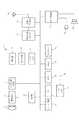
図1は本発明の各実施の形態に共通するカメラ付き携帯電話機(以下、カメラ付き携帯と称する)1の概略構成を示すブロック図である。このカメラ付き携帯1は、デジタルカメラ機能と携帯電話機能とを併有するものであって、レンズユニット2を有し、このレンズユニット2の後方には、CCDからなる撮像素子3が配置されている。この撮像素子3からの出力信号は信号処理回路4により画質モードに応じて処理され、CPU5に取り込まれる。CPU5には、前記撮像素子3、時計部6、ビデオRAM7が接続されているとともに、キー入力部8、ROM10、RAM11、メモリカード12、及びI/Oポート9が接続されている。Hereinafter, an embodiment of the present invention will be described with reference to the drawings.
(First embodiment)
FIG. 1 is a block diagram showing a schematic configuration of a camera-equipped mobilephone (hereinafter referred to as a camera-equipped mobilephone) 1 common to the embodiments of the present invention. This camera-equipped mobile phone 1 has both a digital camera function and a mobile phone function, and has a
時計部6は、現在年月日及び時刻を計時するものである。キー入力部8には、電源のオン・オフ時に操作される電源キー、電話番号を入力する際やメール作成時に使用される複数の文字キー、画像をメモリカード12に記憶させる際に操作されるシャッターボタン等の、一般的なカメラ付き携帯に配置されている各種キーや後述するフローチャートに示す各種キーが設けられている。ROM10にはCPU5のプログラムや、ビザ用、パスポート用等の証明写真の横縦サイズ、Lサイズ、A4サイズ等の印刷用紙の横縦サイズである印刷サイズ、及び各種外部モニタの画面横縦サイズであるモニタサイズ等が記憶されている。CPU5は、前記プログラムに基づき動作し、RAM11をワークメモリとして使用して各部の制御を行う。メモリカード12は着脱自在であって、撮影モードで生成された被写体画像データ等を記録するメモリであり、I/Oポート9は、メモリカード12に記録された画像データ等をシリアルI/O端子15を介して、外部のプリンターあるいはモニタに出力するインタフェースである。The
また、RAM11は、撮像素子3により撮像された後、信号処理回路4によりデジタル化された被写体の画像データを一時保存するバッファとしても使用される。シャッターボタンの操作時にRAM11に一時保存された画像データは、CPU5による撮影処理により圧縮(符号化)が行われ、最終的には所定のフォーマット(JPEG方式等)を備えた静止画データとしてメモリカード12に記録される。なお、本実施の形態においては、メモリカード12へ記録する画像の画像サイズはユーザが選択して設定することが可能である。 The
ビデオRAM7には、サイズガイドモードと撮影モードの状態においては、信号処理回路4で処理された撮像素子3からの出力信号に基づく被写体画像の画像データが所定のタイミング毎に格納される。この画像データに基づき、表示回路13が表示部14を駆動することにより、レンズユニット2により撮像素子3上に結像された被写体画像がスルー画像としてLCDからなる表示部14にて表示される。また、再生モードの状態においては、メモリカード12から読み出された画像データが格納され、この画像データに基づき、表示回路13が表示部14を駆動することにより、記録されている画像データに基づく画像が表示部14にて表示される。表示部14は、カラーLCDであって、本実施の形態においては解像度(横縦)は640×480(dot)である。 In the video RAM 7, image data of a subject image based on the output signal from the
無線送受信部20は、アンテナ21を介してCDMA方式の無線信号を受信し、後段の無線信号処理部22に出力する一方、無線信号処理部22から入力された各種データを無線信号に変調してアンテナ21より出力する。無線信号処理部22は、無線送受信部20で受信した各種データを復調して、パケット送信されたデータ(メールデータや画像データ)を、RAM11に出力する一方、送信の際には、送信するためのデータを変調するなどの無線通信に必要な処理をする。音声処理部23は、無線信号処理部22で復調された音声データに基づきあるいは着信時に、スピーカ24を駆動するとともに、マイク25から入力された音声を電気信号に変換して無線信号処理部22に供給する。 The radio transmission /
以上の構成に係る本実施の形態において、ユーザがキー入力部8でモード設定キーを操作することにより、撮影モードとしてサイズガイドモードを選択すると、CPU5はROM10に記憶されているプログラムに基づき、図2に示すフローチャートに従って制御を実行する。先ず、予めユーザのキー入力部8での操作により設定されているメモリカード12へ記録する画像サイズを取得する(ステップS101)。すなわち、この実施の形態においては前述のように、メモリカード12へ記録する画像の横縦ドット数である画像サイズをユーザが選択して設定可能であり、したがって、例えば選択設定されている画像サイズが2048×1536(dot)であるならば、これを取得する。 In the present embodiment having the above-described configuration, when the user selects the size guide mode as the shooting mode by operating the mode setting key with the
次に、撮影した画像を印刷する際の印刷サイズ又は外部モニタで表示する際のモニタサイズを取得する(ステップS102)。このステップS102での処理に際しては、図3に示すように、表示部14に「1.Lサイズ」〜・・・の印刷サイズ選択メニューと、「1.A×B(mm)」のモニタサイズ選択画面とを表示し(A,B等は実数値)、ユーザがキー入力部8の操作によりこの選択メニューの中からいずれか一つを選択すると、この選択したサイズに決定してRAM11に記憶する。このとき、当該ユーザが所有しているプリンターが、例えばA4サイズの用紙にのみ印刷可能であるA4サイズ専用プリンターである場合には、「2.A4サイズ」を選択する。 Next, a print size for printing the captured image or a monitor size for displaying on the external monitor is acquired (step S102). In the process in step S102, as shown in FIG. 3, the
引き続き、印刷される画像の1mm当たりの(記録)ドット数を演算する(ステップS103)。すなわち、前記ステップS101で取得されたメモリカード12へ記録する画像サイズは2048×1536(dot)であり、また、ステップS102で取得された印刷サイズがA4サイズ(280×210(mm))であるとすると、印刷する画像1mm当たりの(記録)ドット数は、
1mm=2048/280=7.314(dot)
となり、この「7.314(dot)」を印刷1mm当たりのドット数として算出する。Subsequently, the number of (recording) dots per 1 mm of the image to be printed is calculated (step S103). That is, the image size recorded in the
1 mm = 2048/280 = 7.314 (dot)
Thus, “7.314 (dot)” is calculated as the number of dots per 1 mm of printing.
次に、このステップS103で演算した印刷1mm当たりのドット数を、表示部14における表示ドット数に換算する(ステップS104)。つまり、前述のように、表示部14の表示解像度は640×480(dot)であるので、印刷1mm当たりのドット数を表示部14の表示1mm当たりのドット数に換算すると、
1mm=7.314×640/2048=2.285(dot)
となる。さらに、これを表示1cm当たりのドット数に換算すると、22.8(dot)となり、表示5cm当たりのドット数に換算すると、114(dot)となる。Next, the number of dots per 1 mm of printing calculated in step S103 is converted into the number of display dots on the display unit 14 (step S104). That is, as described above, since the display resolution of the
1 mm = 7.314 × 640/2048 = 2.285 (dot)
It becomes. Further, when this is converted into the number of dots per 1 cm of the display, it is 22.8 (dots), and when converted into the number of dots per 5 cm of the display, it is 114 (dots).
そして、スルー画像上に、ステップS104での換算結果に基づくガイド目盛を表示する(ステップS105)。すなわち、前述のようにビデオRAM7には、サイズガイドモードの状態においては、信号処理回路4で処理された撮像素子3からの出力信号に基づく被写体画像の画像データが所定のタイミング毎に格納される。この画像データに基づき、表示回路13が表示部14を駆動することにより、レンズユニット2により撮像素子3上に結像された被写体画像がスルー画像としてLCDからなる表示部14にて表示される。そして、この表示部14に表示されたスルー画像上に前記ステップS104で換算したドット数、例えば図4(a)に示すように、114ドット毎に5cmであることを示す目盛からなる横目盛141と縦目盛142とで構成される交差目盛140を表示させる。 Then, a guide scale based on the conversion result in step S104 is displayed on the through image (step S105). That is, as described above, the video RAM 7 stores the image data of the subject image based on the output signal from the
次に、シャッターボタンが押下されるまで待機し(ステップS106)、その間撮影者は、表示部14の交差目盛140の目盛が印刷時には5cmであることを考慮しながらスルー画像の所望部分が所望の大きさで収まるように、カメラ付き携帯1の向き、あるいは被撮影者(被撮影物)からの距離等を調整する。そして、スルー画像の所望部分が所望の大きさで収まった状態で撮影者がシャッターボタンを操作すると(ステップS106;YES)、前述した撮影処理を実行し(ステップS107)、記録する画像として目盛付きが予めユーザに選択されていたか否かを判断する(ステップS108)。Next, the process waits until the shutter button is pressed (step S106), during which the photographer takes a desired portion of the through image while considering that the scale of the
目盛付きが選択されていた場合には、スルー画像上に交差目盛140が配置された撮影画像の画像データをメモリカード12に記録するとともに、この画像データと関連付けてステップS102で取得された印刷サイズ情報もメモリカード12に記録する(ステップS109)。また、目盛付きが選択されていなかった場合には、撮影画像の画像データをメモリカード12に記録するとともに、この画像データと関連付けてステップS102で取得された印刷サイズ情報をメモリカード12に記録する(ステップS110)。 If scaled is selected, the image data of the photographed image in which the
そして、このようにして証明写真の撮影が終了したならば、カメラ付き携帯1からメモリカード12を取り外し、ユーザが所有するプリンターにセットする。若しくは、カメラ付き携帯1にメモリカード12を装着した状態で、I/O端子15にユーザが所有するプリンターを接続し、I/Oポート9及びシリアルI/O端子15を介して、メモリカード12に記録されている画像データをプリンターに出力する。 When the ID photo has been taken in this manner, the
ここで、当該ユーザが所有しているプリンターが本例のように、A4サイズ専用プリンターである場合には、プリンターは前述したA4サイズで画像データに基づく画像を印刷する。このとき、本例においてはステップS102での処理により、印刷サイズとしてA4が取得されていることから、A4サイズの紙面上には、A4サイズの大きさの画像において所望部分が所望の大きさで収まった画像が印刷されることとなる。 Here, when the printer owned by the user is an A4 size dedicated printer as in this example, the printer prints an image based on the image data in the A4 size described above. At this time, in this example, A4 is acquired as the print size by the processing in step S102. Therefore, a desired portion of the A4 size image has a desired size on the A4 size paper. The stored image is printed.
また、使用するプリンターがLサイズ、A4サイズ、B5サイズ等のサイズの異なる用紙に印刷可能なものである場合には、メモリカード12に画像データと関連付けて記録されている印刷サイズ情報に基づき、プリンターが当該印刷サイズで印刷を行う。したがって、前述と同様に、印刷された画像上には、所望部分が所望の大きさで収まった画像が出現することとなる。 In addition, when the printer to be used is capable of printing on paper of different sizes such as L size, A4 size, and B5 size, based on the print size information recorded in association with the image data on the
したがって、例えばA4サイズの印刷で10×10cmの証明写真を作成する場合には、図4(b)に示すように、ユーザは交差目盛140の10cmの位置を結ぶ枠143を想定し、この枠143内に適正な大きさ及び範囲で被撮影者の上半身が収まった状態でシャッターボタンを操作すれば、適正な大きさ(10×10cm)及び範囲で被撮影者の上半身が収まった画像を印刷することができる。 Therefore, for example, when creating a 10 × 10 cm ID photo by A4 size printing, the user assumes a
また、ステップS111では、ユーザによるキー入力部8での操作によって送信指示があったか否かを判断する(ステップS111)。送信指示があった場合には、前記ステップS109又はS110でメモリカード12に記録した全データを、ネットワークを介して、所定の送信先に送信する(ステップS112)。したがって、このデータを受信した受信者にあっても、前述と同様にして、A4サイズの紙面上に、A4サイズの大きさの画像において(送信者の)所望部分が所望の大きさで収まった画像を印刷することが可能となる。 In step S111, it is determined whether or not a transmission instruction is given by an operation on the
なお、以上の説明においては、ステップS102で印刷サイズを取得した場合を示したが、モニタサイズを取得した場合には、モニタに表示する画像1mm当たりドット数を演算する(ステップS103)。次に、取得したモニタサイズと表示部14の表示画面サイズとのサイズ比に基づき、ステップS103で演算した当該モニタ表示1mm当たりのドット数を、表示部14における表示ドット数に換算する(ステップS104)。さらに、ステップS105で、前記ステップS104での換算結果に基づくガイド目盛を表示し、ステップS106〜S112で同様の処理を実行する。 In the above description, the case where the print size is acquired in step S102 is shown. However, when the monitor size is acquired, the number of dots per 1 mm of the image displayed on the monitor is calculated (step S103). Next, based on the size ratio between the acquired monitor size and the display screen size of the
そして、同様に証明写真の撮影が終了したならば、カメラ付き携帯1からメモリカード12を取り外し、前記ユーザが選択したサイズのモニタを有する画像再生装置等にセットする。若しくは、カメラ付き携帯1にメモリカード12を装着した状態で、I/O端子15に前記画像再生装置を接続し、I/Oポート9及びシリアルI/O端子15を介して、メモリカード12に記録されている画像データをモニタに出力する。これにより、このモニタには、当該モニタサイズの大きさの画像において所望部分が所望の大きさで収まった画像が表示されることとなる。 Similarly, when the ID photo has been taken, the
なお、本実施の形態においては、ステップS105での処理により、サイズガイドとして表示部14の中央部に交差目盛140を表示させるようにしたが、サイズガイドはこれに限らず、表示部14の側部に目盛を表示したり、図4(a)に示した目盛の各数値を結ぶ枠を表示したり、あるいは当該印刷サイズにおけるビザ用、パスポート用等の証明写真の横縦サイズを目盛や枠で表示するもの等であってもよい。 In the present embodiment, the
(第2の実施の形態)
図5は、本発明の第2の実施の形態における処理手順を示すフローチャートである。このフローチャートにおいて、ステップS201〜S205の処理、及びステップS208〜S214の処理は、図2に示したフローチャートにおける全ステップS101〜S112と同様の処理であり、ステップS206及びステップS207の処理のみが異なる。(Second Embodiment)
FIG. 5 is a flowchart showing a processing procedure in the second embodiment of the present invention. In this flowchart, the processes in steps S201 to S205 and the processes in steps S208 to S214 are the same as those in all steps S101 to S112 in the flowchart shown in FIG. 2, and only the processes in steps S206 and S207 are different.
そして、ステップS206においては、ユーザによるキー入力部8での操作により縮小、拡大指示があったか否かを判断する。つまり、ユーザは撮影後に画像を縮小印刷(表示)したり拡大印刷(表示)する予定であるか否かを考慮して、縮小印刷する予定である場合には、キー入力部8での操作により縮小倍率値を入力して縮小指示し、拡大印刷する予定である場合には拡大倍率値を入力して拡大指示する。これにより、ステップS206の判断がYESになると、ステップS207で縮小、拡大倍率に応じてガイドスケールの目盛のスケールを変更する。In step S206, it is determined whether or not a reduction / enlargement instruction is given by an operation of the
したがって、図4(a)に示したように、114ドット毎に5cmであることを示す目盛からなる横目盛141と縦目盛142とで構成される交差目盛140が状態において、例えば縮小率1/2倍を指示すると、交差目盛140のスケールは2倍になり、228ドット毎に5cmであることを示す目盛からなる横目盛141と縦目盛142とで構成される交差目盛140に変更される。また、例えば拡大率2倍を指示すると、交差目盛140のスケールは1/2倍になり、57ドット毎に5cmであることを示す目盛からなる横目盛141と縦目盛142とで構成される交差目盛140に変更される。 Therefore, as shown in FIG. 4A, in the state where the
そこで、撮影者は表示部14の交差目盛140の目盛が印刷時には5cmであることを考慮しながらスルー画像の所望部分が所望の大きさで収まるように、カメラ付き携帯1の向き、あるいは被撮影者(被撮影物)からの距離等を調整する。そして、スルー画像の所望部分が所望の大きさで収まった状態で撮影者がシャッターボタンを操作すると(ステップS208;YES)、前述した撮影処理を実行し(ステップS209)、記録する画像として目盛付きが予めユーザに選択されていたか否かを判断する(ステップS210)。Therefore, the photographer considers that the scale of the
目盛付きが選択されていた場合には、スルー画像上に交差目盛140が配置された撮影画像の画像データをメモリカード12に記録するとともに、この画像データと関連付けてステップS202で取得された印刷サイズ情報及びステップS207で用いた縮小、拡大倍率をメモリカード12に記録する(ステップS211)。また、目盛付きが選択されていなかった場合には、撮影画像の画像データをメモリカード12に記録するとともに、この画像データと関連付けてステップS202で取得された印刷サイズ情報及びステップS207で用いた縮小、拡大倍率をメモリカード12に記録する(ステップS110)。 また、ステップS213では、ユーザによるキー入力部8での操作によって送信指示があったか否かを判断する。送信指示があった場合には、前記ステップS211又はS212でメモリカード12に記録した全データを、ネットワークを介して、所定の送信先に送信する(ステップS214)。 If scaled is selected, the image data of the photographed image in which the
したがって、本実施の形態によれば撮影後ユーザがメモリカード12に記録されている画像データに基づく画像を前記指示した縮小、拡大倍率で、撮影画像をプリンタで印刷しあるいはモニタに表示させた際には、画像における所望の部分が所望の縮小、拡大倍率で印刷、表示された画像を得ることができる。 Therefore, according to the present embodiment, after the user has taken the image based on the image data recorded on the
(第3の実施の形態)
図6は、本発明の第3の実施の形態における処理手順を示すフローチャートである。電源オン状態になると、CPU5はROM10に記憶されているプログラムに基づき、このフローチャートに従って制御を実行する。すなわち、ユーザがキー入力部8で所望の画質モード(高画質モードと低画質モードとのいずれか)を選択することにより画質モード設定操作を行うと、選択された画質モードが設定される(ステップS301)。また、ユーザがキー入力部8で所望の撮影モードを選択することにより撮影モード設定操作を行うと、選択された撮影モードが設定される(ステップS302)。さらに撮影モードのうち証明写真モードが選択されたか否かを判断し(ステップS303)、証明写真モードが選択されなかった場合には、選択された撮影モードに応じた撮影処理に移行する。(Third embodiment)
FIG. 6 is a flowchart showing a processing procedure in the third embodiment of the present invention. When the power is turned on, the
また、証明写真モードが選択された場合には、証明写真の種類を選択する処理を実行する(ステップS304)。すなわち、表示部14に図7(a)に示した証明写真選択メニューを表示して、ユーザがキー入力部8の操作によりこの証明写真選択メニューの中からいずれか一つを選択すると、この選択した証明写真の種類に決定してRAM11に記憶する。 If the ID photo mode is selected, a process for selecting the ID photo type is executed (step S304). That is, when the ID photo selection menu shown in FIG. 7A is displayed on the
次に、前記ステップS301で選択された画質モードにおいてメモリカード12へ記録する画像サイズを取得する(ステップS305)。したがって、例えば選択設定されている画質モードにおける画像サイズが2048×1536(dot)であるならば、これを取得する。 Next, the image size to be recorded on the
次に、撮影した画像を印刷する際の印刷サイズを取得する(ステップS306)。このステップS306での処理に際しては、図7(b)に示したように、表示部14に「1.Lサイズ」〜・・・の印刷サイズ選択メニューを表示し、ユーザがキー入力部8の操作によりこの選択メニューの中からいずれか一つを選択すると、この選択したサイズに決定してRAM11に記憶する。このとき、当該ユーザが所有しているプリンターが、例えばA4サイズの用紙にのみ印刷可能であるA4サイズ専用プリンターである場合には、「2.A4サイズ」を選択する。 引き続き、印刷される画像の1mm当たりの(記録)ドット数を演算する(ステップS307)。すなわち、前記ステップS305で取得されたメモリカード12へ記録する画像サイズは2048×1536(dot)であり、また、ステップS306で取得された印刷サイズが、280×210(mm)であるとすると、印刷する画像1mm当たりの(記録)ドット数は、
1mm=2048/280=7.314(dot)
となり、この「7.314(dot)」を印刷1mm当たりのドット数として算出する。Next, a print size for printing the photographed image is acquired (step S306). In the process in step S306, as shown in FIG. 7B, a print size selection menu of “1.L size” to... Is displayed on the
1 mm = 2048/280 = 7.314 (dot)
Thus, “7.314 (dot)” is calculated as the number of dots per 1 mm of printing.
次に、このステップS103で演算した印刷1mm当たりのドット数を、表示部14における表示ドット数に換算する(ステップS308)。つまり、前述のように、表示部14の表示解像度は640×480(dot)であるので、印刷1mm当たりのドット数を表示部14の表示1mm当たりのドット数に換算すると、
1mm=7.314×640/2048=2.285(dot)
となる。さらに、これを表示1cm当たりのドット数に換算すると、約22(dot)となる。Next, the number of dots per 1 mm of printing calculated in step S103 is converted into the number of display dots on the display unit 14 (step S308). That is, as described above, since the display resolution of the
1 mm = 7.314 × 640/2048 = 2.285 (dot)
It becomes. Furthermore, when this is converted into the number of dots per 1 cm of display, it isabout 22 (dots).
次に、選択された証明写真用のガイド目盛を、現在設定されている画質モード及び印刷サイズに応じた長さでスルー画像上に(ガイダンスを伴って)表示する(ステップS309)。すなわち、ビデオRAM7には、証明写真モードの状態においては、信号処理回路4で処理された撮像素子3からの出力信号に基づく被写体画像の画像データが所定のタイミング毎に格納される。この画像データに基づき、表示回路13が表示部14を駆動することにより、レンズユニット2により撮像素子3上に結像された被写体画像がスルー画像としてLCDからなる表示部14にて表示される。そして、この表示部14に表示されたスルー画像上に前記ステップS308で換算したドット数、例えば図7(c)に示すように、22ドット毎に1cmであることを示す目盛からなる横目盛141と縦目盛142とで構成される直角目盛144を表示させる。また、このとき、ステップS304での処理により、証明写真の種類は取得されていることから、横目盛141と縦目盛142の長さを証明写真の長さとする。さらに、直角目盛144の外部に「笑ってはいけない」「背景は白」「ピン止めはしない」等のガイダンスGも表示する。 Next, the guide scale for the selected ID photo is displayed on the through image (with guidance) in a length corresponding to the currently set image quality mode and print size (step S309). That is, in the state of the ID photo mode, the video RAM 7 stores the image data of the subject image based on the output signal from the
次に、シャッターボタンが押下されるまで待機し(ステップS310)、その間撮影者は、表示部14を見ながら直交目盛144の内側に被撮影者の上半身が適正な範囲で収まるように、カメラ付き携帯1の向き、あるいは被撮影者からの距離等を調整する。そして、直交目盛144の内側に適正な範囲で被撮影者の上半身が収まった状態で撮影者がシャッターボタンを操作すると(ステップS310;YES)、現在設定されている画質モードで撮影処理を実行し(ステップS311)、スルー画像上に直交目盛144が配置された撮影画像の画像データをメモリカード12に記録する(ステップS312)。 Next, the process waits until the shutter button is pressed (step S310). During that time, the photographer attaches the camera so that the upper body of the subject is within the proper range inside the
そして、このようにして証明写真の撮影が終了したならば、カメラ付き携帯1からメモリカード12を取り外し、ユーザが所有するプリンターにセットする。若しくは、カメラ付き携帯1にメモリカード12を装着した状態で、I/O端子15にユーザが所有するプリンターを接続し、I/Oポート9及びシリアルI/O端子15を介して、メモリカード12に記録されている画像データをプリンターに出力する。 When the ID photo has been taken in this manner, the
このとき、前述のステップS309での処理により、画質モード及び印刷サイズに対応する大きさから成る証明写真の直交目盛144をスルー画像上に表示し、かつステップS312での処理より、直交目盛144のデータも記録したことから、A4サイズで印刷された画像上には、ステップS304で選択された証明写真の縦横サイズを有する直交目盛144が印刷されるとともに、直交目盛144内に適正な大きさ及び範囲で被撮影者の上半身が収まった画像が印刷される。したがって、印刷後、直交目盛144に沿って印刷用紙を切断することにより、使用可能な規定のサイズからなり、かつ、適正な範囲で上半身の画像が印刷された証明写真を完成させることができる。 At this time, the
しかも、一般に証明写真のサイズは、低画質モードで撮影して印刷した画像のサイズよりも小さいことから、低画質モードで撮影しておいても証明写真のサイズに支障を来すことはない。よって、低画質モードが設定された場合には、小さいサイズの印刷用紙を使用し、かつ少ないインクで経済的に印刷を行うことができる。 In addition, since the size of the ID photo is generally smaller than the size of the image taken and printed in the low image quality mode, the ID photo size is not hindered even if the ID photo is taken. Therefore, when the low image quality mode is set, printing can be performed economically using a small size printing paper and using a small amount of ink.
(第4の実施の形態)
図8は、本発明の第4の実施の形態における処理手順を示すフローチャートである。(Fourth embodiment)
Figure 8 isRu flowchart der showing a processing procedure in the fourth embodiment of the presentinvention.
電源オン状態になると、CPU5はROM10に記憶されているプログラムに基づき、図8に示すフローチャートに従って制御を実行する。すなわち、ユーザがキー入力部8で所望の撮影モードを選択することにより撮影モード設定操作を行うと、選択された撮影モードが設定される(ステップS401)。さらに撮影モードのうち証明写真モードが選択されたか否かを判断し(ステップS402)、証明写真モードが選択されなかった場合には、選択された撮影モードに応じた撮影処理に移行する。 When the power is turned on, the
また、証明写真モードが選択された場合には、画質モードを強制的に低画質モードに切り換える(ステップS403)。さらに、前述したステップS304での処理と同様に証明写真の種類を選択する処理を実行する(ステップS404)。 If the ID photo mode is selected, the image quality mode is forcibly switched to the low image quality mode (step S403). Further, a process for selecting the type of ID photo is performed in the same manner as the process in step S304 described above (step S404).
次に、前記ステップS401で強制的に設定された低画質モードにおいてメモリカード12へ記録する画像サイズを取得する(ステップS405)。したがって、低画質モードにおける画像サイズが2048×1536(dot)であるならば、これを取得する。 Next, the image size to be recorded on the
次に、撮影した画像を印刷する際の印刷サイズを取得する(ステップS406)。このステップS406での処理に際しては、前述と同様に図7(b)に示したように、表示部14に「1.Lサイズ」〜・・・の印刷サイズ選択メニューを表示し、ユーザがキー入力部8の操作によりこの選択メニューの中からいずれか一つを選択すると、この選択したサイズに決定してRAM11に記憶する。このとき、当該ユーザが所有しているプリンターが、例えばA4サイズの用紙にのみ印刷可能であるA4サイズ専用プリンターである場合には、「2.A4サイズ」を選択する。 Next, the print size for printing the captured image is acquired (step S406). In the process in step S406, as shown in FIG. 7B, a print size selection menu of “1.L size” to... Is displayed on the
引き続き、印刷される画像の1mm当たりの(記録)ドット数を演算する(ステップS407)。すなわち、前記ステップS405で取得されたメモリカード12へ記録する画像サイズは2048×1536(dot)であり、また、ステップS406で取得された印刷サイズが、280×210(mm)であるとすると、印刷する画像1mm当たりの(記録)ドット数は、
1mm=2048/280=7.314(dot)
となり、この「7.314(dot)」を印刷1mm当たりのドット数として算出する。Subsequently, the number of (recording) dots per mm of the image to be printed is calculated (step S407). That is, if the image size recorded in the
1 mm = 2048/280 = 7.314 (dot)
Thus, “7.314 (dot)” is calculated as the number of dots per 1 mm of printing.
次に、このステップS103で演算した印刷1mm当たりのドット数を、表示部14における表示ドット数に換算する(ステップS408)。つまり、前述のように、表示部14の表示解像度は640×480(dot)であるので、印刷1mm当たりのドット数を表示部14の表示1mm当たりのドット数に換算すると、
1mm=7.314×640/2048=2.285(dot)
となる。さらに、これを表示1cm当たりのドット数に換算すると、約22(dot)となる。Next, the number of dots per 1 mm of printing calculated in step S103 is converted into the number of display dots on the display unit 14 (step S408). That is, as described above, since the display resolution of the
1 mm = 7.314 × 640/2048 = 2.285 (dot)
It becomes. Furthermore, when this is converted into the number of dots per 1 cm of display, it isabout 22 (dots).
次に、選択された証明写真用のガイド目盛をスルー画像上に(ガイダンスを伴って)表示する(ステップS409)。すなわち、ビデオRAM7には、証明写真モードの状態においては、信号処理回路4で処理された撮像素子3からの出力信号に基づく被写体画像の画像データが所定のタイミング毎に格納される。この画像データに基づき、表示回路13が表示部14を駆動することにより、レンズユニット2により撮像素子3上に結像された被写体画像がスルー画像としてLCDからなる表示部14にて表示される。そして、この表示部14に表示されたスルー画像上に前記ステップS408で換算したドット数、例えば前記図7(c)に示したように、22ドット毎に1cmであることを示す目盛からなる横目盛141と縦目盛142とで構成される直角目盛144を表示させる。また、このとき、ステップS404での処理により、証明写真の種類は取得されていることから、横目盛141と縦目盛142の長さを証明写真の長さとする。さらに、直角目盛144の前記ガイダンスGも表示する。 Next, the guide scale for the selected ID photo is displayed on the through image (with guidance) (step S409). That is, in the state of the ID photo mode, the video RAM 7 stores the image data of the subject image based on the output signal from the
次に、シャッターボタンが押下されるまで待機し(ステップS410)、その間撮影者は、表示部14を見ながら直交目盛144内に被撮影者の上半身が適正な範囲で収まるように、カメラ付き携帯1の向き、あるいは被撮影者からの距離等を調整する。そして、直交目盛144内に適正な範囲で被撮影者の上半身が収まった状態で撮影者がシャッターボタンを操作すると(ステップS410;YES)、低画質モードで撮影処理を実行し(ステップS407)、スルー画像上に直交目盛144が配置された低画質モードでの撮影画像の画像データをメモリカード12に記録する(ステップS412)。 Next, the process waits until the shutter button is pressed (step S410). During that time, the photographer carries the camera-equipped mobile phone so that the upper body of the photographed person falls within an appropriate range within the
そして、このようにして証明写真の撮影が終了したならば、カメラ付き携帯1からメモリカード12を取り外し、ユーザが所有するプリンターにセットする。若しくは、カメラ付き携帯1にメモリカード12を装着した状態で、I/O端子15にユーザが所有するプリンターを接続し、I/Oポート9及びシリアルI/O端子15を介して、メモリカード12に記録されている画像データをプリンターに出力する。 When the ID photo has been taken in this manner, the
このとき、前述のステップS405での処理により、画質モードに対応する大きさから成る証明写真の直交目盛144をスルー画像上に表示し、かつステップS412での処理より、直交目盛144のデータも記録したことから、印刷された画像上には、ステップS404で選択された証明写真の縦横サイズを有する直交目盛144が印刷されるとともに、直交目盛144内に適正な大きさ及び範囲で被撮影者の上半身が収まった画像が印刷される。したがって、印刷後、直交目盛144に沿って印刷用紙を切断することにより、使用可能な規定のサイズからなり、かつ、適正な範囲で上半身の画像が印刷された証明写真を完成させることができる。 At this time, the
しかも、一般に証明写真のサイズは、低画質モードで撮影して印刷した画像のサイズよりも小さいことから、低画質モードで撮影しておいても証明写真のサイズに支障を来すことはない。よって、強制的に低画質モードに切り換えて撮影することにより、低画質モードで撮影して印刷するよりも少ないインクで経済的に印刷を行うことができる。 In addition, since the size of the ID photo is generally smaller than the size of the image taken and printed in the low image quality mode, the ID photo size is not hindered even if the ID photo is taken. Therefore, by forcibly switching to the low image quality mode and shooting, it is possible to print economically with less ink than when shooting and printing in the low image quality mode.
なお、実施の形態においては、画像データに関連付けて印刷サイズ情報をメモリカードに記録するようにしたが、印刷サイズ情報を記録しなくてもよい。この場合、ユーザは撮影時に設定した印刷サイズを覚えておいて、当該印刷サイズ専用のプリンターを使用し、また、使用するプリンターがLサイズ、A4サイズ、B5サイズ等のサイズの異なる用紙に印刷可能なものである場合には、覚えておいた印刷サイズを手動でプリンターに設定することになる。 In the embodiment, the print size information is recorded on the memory card in association with the image data. However, the print size information may not be recorded. In this case, the user remembers the print size set at the time of shooting, uses a printer dedicated to the print size, and the printer to be used can print on paper of different sizes such as L size, A4 size, B5 size, etc. If this is the case, the remembered print size is manually set in the printer.
また、第3の実施の形態においては、高画質モードが設定されていた場合は、スルー画像上に表示される直交目盛144の大きさがかなり小さくなってしまい、撮影画像上の極めて少ない部分のみが必要となるので、当該部分のみを抽出して記録するようにしてもよい。これより、不要な部分の印刷を回避してインクを節約することができる。 In the third embodiment, when the high image quality mode is set, the size of the
さらに、第4の実施の形態においては、証明写真モードを選択した時点で画質モードを低画質モードに切り換えるようにしたが、証明写真の種類を選択した時点で証明写真の種類に応じた画質モードに自動的に切り換えるようにしてもよい。これにより、証明写真の種類によって必要とする印刷サイズが大きく異なる場合であっても、必要な印刷サイズを確保し得るサイズの画像を記録することができる。 Furthermore, in the fourth embodiment, when the ID photo mode is selected, the image quality mode is switched to the low image quality mode. However, when the ID photo type is selected, the image quality mode corresponding to the ID photo type is selected. You may make it switch automatically. As a result, even when the required print size varies greatly depending on the type of ID photo, an image having a size that can ensure the required print size can be recorded.
また、第3、第4の実施の形態においては、いずれも証明写真用の直交目盛144外にもスルー画像を表示させるようにしたが、直交目盛144内のみスルー画像を表示させるようにしてもよい。 In the third and fourth embodiments, the through image is displayed outside the
また、第3、第4の実施の形態においては、いずれもビザ用、パスポート用等の証明写真を撮影するための証明写真モードに本発明を適用した場合について説明したが、本発明はこれに限るものではなく、ハート形状、円形、テープ(ビデオ)ラベル形状、ディスクラベル形状、名刺形状等のフレーム(目盛144)をスルー画像上に表示して撮影モードに適用してもよく、必要とする印刷サイズが決まっているものであれば本発明を適用することができる。 In the third and fourth embodiments, the case where the present invention is applied to the ID photo mode for taking ID photos for visa, passport, etc. has been described. The frame (scale 144) such as a heart shape, a circle, a tape (video) label shape, a disc label shape, and a business card shape may be displayed on the through image and applied to the shooting mode. The present invention can be applied as long as the print size is determined.
また、第1、第2、第3、第4の実施の形態においては、いずれも本発明をカメラ付き携帯に適用した場合について説明したが、本発明はこれに限るものではなく、他にもデジタルスチルカメラ、カメラ付きPDA(Personal Digital Assistants:携帯情報端末)、カメラ付きパーソナルコンピュータ、等に適用することも容易に可能であり、撮像機能が搭載された装置であればいずれにも適用することができる。 In the first, second, third, and fourth embodiments, the case where the present invention is applied to a camera-equipped mobile phone has been described. However, the present invention is not limited thereto, and It can be easily applied to a digital still camera, a PDA with a camera (Personal Digital Assistants), a personal computer with a camera, etc., and can be applied to any apparatus equipped with an imaging function. Can do.
1 カメラ付き携帯
3 撮像素子
4 信号処理回路
5 CPU
7 ビデオRAM
8 キー入力部
9 I/Oポート
10 ROM
11 RAM
12 メモリカード
13 表示回路
14 表示部
15 シリアルI/O端子
144 直交目盛
G ガイダンス
P 印刷サイズ
S スルー画像
DESCRIPTION OF SYMBOLS 1 Mobile phone with
7 Video RAM
8 Key input section 9 I /
11 RAM
12
Claims (8)
Translated fromJapaneseこの撮像手段から出力される画像データを表示する表示手段と、
複数種類の印刷媒体のサイズの中から1つを選択する選択手段と、
前記画像データが印刷媒体に印刷された際の実サイズを示すサイズガイドを前記表示手段に表示させると共に、前記選択手段にて選択された印刷媒体サイズに応じて前記サイズガイドの縮尺又は倍尺を調整する表示制御手段と
を備えることを特徴とする撮像装置。Imaging means for imaging a subject and outputting image data;
Display means for displaying image data output from the imaging means;
Selection means for selecting one ofthe size of thedouble severalprinting media,
A size guide indicating the actual size when the image data isprinted on a print medium is displayed on the display unit, and a scale or scale of the size guide is set according to theprint medium size selected by the selection unit. An image pickup apparatus comprising: display control means for adjusting.
この撮像手段から出力される画像データを表示する表示手段と、
複数種類の外部モニタサイズの中から1つを選択する選択手段と、
前記画像データが外部モニタに表示された際の実サイズを示すサイズガイドを前記表示手段に表示させると共に、前記選択手段にて選択された外部モニタサイズに応じて前記サイズガイドの縮尺又は倍尺を調整する表示制御手段と
を備えることを特徴とする撮像装置。Imaging means for imaging a subject and outputting image data;
Display means for displaying image data output from the imaging means;
A selection means for selecting one of a plurality ofexternal monitor sizes ;
A size guide indicating the actual size when the image data isdisplayed on theexternal monitor is displayed on the display means, and the scale or scale of the size guide is set according to theexternal monitor size selected by the selection means. An image pickup apparatus comprising: display control means for adjusting.
この撮像手段から出力される画像データを表示する表示手段と、
複数種類の印刷媒体のサイズの中から1つを選択するサイズ選択手段と、
前記画像データを縮小又は拡大する倍率を、複数種類の中から1つ選択する倍率選択手段と、
前記画像データが印刷媒体に印刷された際の実サイズを示すサイズガイドを前記表示手段に表示させると共に、前記サイズ選択手段にて選択された印刷媒体サイズ及び前記倍率選択手段にて選択された倍率に応じて、前記サイズガイドの縮尺又は倍尺を調整する表示制御手段と
を備えることを特徴とする撮像装置。Imaging means for imaging a subject and outputting image data;
Display means for displaying image data output from the imaging means;
Size selection means for selecting one of the sizesofa plurality of types of print media;
A magnification selection means for selecting one of a plurality of types of magnifications for reducing or enlarging the image data;
A size guide indicating the actual size when the image datais printed on a print mediumisdisplayed on the display means, and the print medium size selected by the size selection means and the magnification selected by the magnification selection means Display control means for adjusting the scale or scale of the size guide according to
Imaging device according to claim Rukotoequipped with.
この撮像手段から出力される画像データを表示する表示手段と、
複数種類の外部モニタサイズの中から1つを選択するサイズ選択手段と、
前記画像データを縮小又は拡大する倍率を、複数種類の中から1つ選択する倍率選択手段と、
前記画像データが外部モニタに表示された際の実サイズを示すサイズガイドを前記表示手段に表示させると共に、前記サイズ選択手段にて選択された外部モニタサイズ及び前記倍率選択手段にて選択された倍率に応じて、前記サイズガイドの縮尺又は倍尺を調整する表示制御手段と
を備えることを特徴とする撮像装置。Imaging means for imaging a subject and outputting image data;
Display means for displaying image data output from the imaging means;
Size selection means for selecting one of a plurality of types of external monitor sizes;
A magnification selection means for selecting one of a plurality of types of magnifications for reducing or enlarging the image data;
A size guide indicating the actual size when the image data is displayed on the external monitor is displayed on the display means, and the external monitor size selected by thesize selection meansand the magnification selected by the magnification selection means And a display control means for adjusting the scale or scale of the size guide according tothe above.
前記画像データが印刷媒体に印刷された際の実サイズを示すサイズガイドを前記表示手段に表示させると共に、前記選択手段にて選択された印刷媒体サイズに応じて前記サイズガイドの縮尺又は倍尺を調整する表示制御手段として機能させることを特徴とする撮像制御プログラム。Comprising imaging means for outputting an image data by imaging a subject, and display means for displaying the image data output from the imaging means,and selection means for selecting one ofthe size of thedouble severalprint mediaA computer included in the imaging apparatus ;
A size guide indicating the actual size when the image data isprinted on a print medium is displayed on the display unit, and a scale or scale of the size guide is set according to theprint medium size selected by the selection unit. imagingcontrol program characterized Rukototo function as a display control means for adjusting.
前記画像データが外部モニタに表示された際の実サイズを示すサイズガイドを前記表示手段に表示させると共に、前記選択手段にて選択された外部モニタサイズに応じて前記サイズガイドの縮尺又は倍尺を調整する表示制御手段として機能させることを特徴とする撮像制御プログラム。Imaging comprising imaging means for outputting an image data by imaging a subject, and display means for displaying the image data output from the imaging means,and selection means for selecting one ofthemultiple severalexternal monitor sizeThe computer that thedevice has
A size guide indicating the actual size when the image data is displayed on the external monitor is displayed on the display means, and the scale or scale of the size guide is set according to theexternal monitor size selected by the selection means. imagingcontrol program characterized Rukototo function as a display control means for adjusting.
前記画像データが印刷媒体に印刷された際の実サイズを示すサイズガイドを前記表示手段に表示させると共に、前記サイズ選択手段にて選択された印刷媒体及び前記倍率選択手段にて選択された倍率に応じて、前記サイズガイドの縮尺又は倍尺を調整する表示制御手段として機能させることを特徴とする撮像制御プログラム。Imaging means for imaging a subject and outputting image data, display means for displaying image data output from the imaging means,size selection means for selecting one of aplurality of types of print media, and the image A computer included in an imaging apparatus including amagnification selection unit that selects oneof a plurality of types ofmagnifications forreducing or enlarging data;
The size guide that indicates the actual size when the image data isprinted on the print medium together with the display on the display unit, the selectedmagnification atselected print medium and the ratio selecting meansby saidsize selecting means In response, an imaging control program that functions as display control means for adjusting the scale or scale of the size guide.
前記画像データが外部モニタに表示された際の実サイズを示すサイズガイドを前記表示手段に表示させると共に、前記サイズ選択手段にて選択された外部モニタサイズ及び前記倍率選択手段にて選択された倍率に応じて、前記サイズガイドの縮尺又は倍尺を調整する表示制御手段として機能させることを特徴とする撮像制御プログラム。An imaging unit that images a subject and outputs image data; a display unit that displays image data output from the imaging unit; asize selection unit that selects one of a plurality of types ofexternal monitor sizes; A computer included in an imaging apparatus includinga magnification selection unit that selectsone of a plurality of types of magnifications for reducing or enlarging image data ;
Magnification the image data the size guide that indicates the actual size whendisplayed on the external monitor causes display on the display unit, is selected bythe external monitor size and the magnification selectionmeans selected by thesize selecting means inresponse, the imaging control program for causing to function as a display control means for adjusting the scale or an enlarged scale of the size guide.
Priority Applications (1)
| Application Number | Priority Date | Filing Date | Title |
|---|---|---|---|
| JP2004155019AJP4827159B2 (en) | 2004-05-25 | 2004-05-25 | Imaging apparatus and imaging control program |
Applications Claiming Priority (1)
| Application Number | Priority Date | Filing Date | Title |
|---|---|---|---|
| JP2004155019AJP4827159B2 (en) | 2004-05-25 | 2004-05-25 | Imaging apparatus and imaging control program |
Publications (3)
| Publication Number | Publication Date |
|---|---|
| JP2005341052A JP2005341052A (en) | 2005-12-08 |
| JP2005341052A5 JP2005341052A5 (en) | 2007-02-22 |
| JP4827159B2true JP4827159B2 (en) | 2011-11-30 |
Family
ID=35494135
Family Applications (1)
| Application Number | Title | Priority Date | Filing Date |
|---|---|---|---|
| JP2004155019AExpired - Fee RelatedJP4827159B2 (en) | 2004-05-25 | 2004-05-25 | Imaging apparatus and imaging control program |
Country Status (1)
| Country | Link |
|---|---|
| JP (1) | JP4827159B2 (en) |
Families Citing this family (2)
| Publication number | Priority date | Publication date | Assignee | Title |
|---|---|---|---|---|
| JP4905017B2 (en)* | 2006-09-22 | 2012-03-28 | カシオ計算機株式会社 | Image display apparatus and program |
| JP2013090241A (en)* | 2011-10-20 | 2013-05-13 | Nikon Corp | Display control device, imaging device, and display control program |
- 2004
- 2004-05-25JPJP2004155019Apatent/JP4827159B2/ennot_activeExpired - Fee Related
Also Published As
| Publication number | Publication date |
|---|---|
| JP2005341052A (en) | 2005-12-08 |
Similar Documents
| Publication | Publication Date | Title |
|---|---|---|
| JP4039775B2 (en) | Image communication system, digital camera constituting the system, and operation control method thereof | |
| US20060221198A1 (en) | User established variable image sizes for a digital image capture device | |
| US10545400B2 (en) | Non-transitory computer readable medium that causes an electronic device to transmit based on recipient information | |
| KR100619150B1 (en) | Image transmission/reception system, image transmission apparatus and image reception apparatus | |
| CN1837939B (en) | Mobile communication terminal having camera function and method for performing the same | |
| JP4534249B2 (en) | Imaging apparatus and program thereof | |
| WO2009087962A1 (en) | Image processing unit | |
| JP2002521971A (en) | Digital handheld keyboard-oriented device with camera providing multiple key data and control inputs, display, wireless communication and data processing, and communication | |
| JP2002057936A (en) | Electronic camera | |
| JP4827159B2 (en) | Imaging apparatus and imaging control program | |
| JP3855783B2 (en) | Printing system | |
| US20050243359A1 (en) | Image data communication system, and image server and portable electronic device and methods of controlling the same | |
| JP3855149B2 (en) | Image transmitting apparatus and printing system | |
| JP6007629B2 (en) | Image processing apparatus, image processing system, and program | |
| JP4239583B2 (en) | Imaging apparatus and imaging control program | |
| JP2005123930A (en) | Mobile terminal device | |
| US20060285153A1 (en) | Image forming apparatus having an integrated camera unit | |
| JP3988075B2 (en) | Image transmission equipment | |
| JP2005010903A (en) | Electronics | |
| JP2004235804A (en) | Mobile terminal equipment | |
| JP4648446B2 (en) | Portable image transceiver | |
| JP2006191343A (en) | Image processing method and imaging apparatus | |
| JP2005244998A (en) | Imaging apparatus and imaging control program | |
| JP2008289181A (en) | Imaging apparatus and imaging control program | |
| JP2006191173A (en) | IMAGING DEVICE, IMAGING DEVICE SYSTEM WITH PRINTER, AND PRINTER |
Legal Events
| Date | Code | Title | Description |
|---|---|---|---|
| A521 | Request for written amendment filed | Free format text:JAPANESE INTERMEDIATE CODE: A523 Effective date:20061228 | |
| A621 | Written request for application examination | Free format text:JAPANESE INTERMEDIATE CODE: A621 Effective date:20061228 | |
| A977 | Report on retrieval | Free format text:JAPANESE INTERMEDIATE CODE: A971007 Effective date:20090305 | |
| A131 | Notification of reasons for refusal | Free format text:JAPANESE INTERMEDIATE CODE: A131 Effective date:20090317 | |
| A521 | Request for written amendment filed | Free format text:JAPANESE INTERMEDIATE CODE: A523 Effective date:20090515 | |
| A02 | Decision of refusal | Free format text:JAPANESE INTERMEDIATE CODE: A02 Effective date:20090616 | |
| A521 | Request for written amendment filed | Free format text:JAPANESE INTERMEDIATE CODE: A523 Effective date:20110721 | |
| A01 | Written decision to grant a patent or to grant a registration (utility model) | Free format text:JAPANESE INTERMEDIATE CODE: A01 | |
| A61 | First payment of annual fees (during grant procedure) | Free format text:JAPANESE INTERMEDIATE CODE: A61 Effective date:20110909 | |
| FPAY | Renewal fee payment (event date is renewal date of database) | Free format text:PAYMENT UNTIL: 20140922 Year of fee payment:3 | |
| R150 | Certificate of patent or registration of utility model | Ref document number:4827159 Country of ref document:JP Free format text:JAPANESE INTERMEDIATE CODE: R150 Free format text:JAPANESE INTERMEDIATE CODE: R150 | |
| LAPS | Cancellation because of no payment of annual fees |