JP4825715B2 - Suspension arm support structure - Google Patents
Suspension arm support structureDownload PDFInfo
- Publication number
- JP4825715B2 JP4825715B2JP2007092804AJP2007092804AJP4825715B2JP 4825715 B2JP4825715 B2JP 4825715B2JP 2007092804 AJP2007092804 AJP 2007092804AJP 2007092804 AJP2007092804 AJP 2007092804AJP 4825715 B2JP4825715 B2JP 4825715B2
- Authority
- JP
- Japan
- Prior art keywords
- arm
- bush
- suspension arm
- receiving member
- side support
- Prior art date
- Legal status (The legal status is an assumption and is not a legal conclusion. Google has not performed a legal analysis and makes no representation as to the accuracy of the status listed.)
- Expired - Fee Related
Links
Images


Classifications
- B—PERFORMING OPERATIONS; TRANSPORTING
- B60—VEHICLES IN GENERAL
- B60G—VEHICLE SUSPENSION ARRANGEMENTS
- B60G3/00—Resilient suspensions for a single wheel
- B60G3/18—Resilient suspensions for a single wheel with two or more pivoted arms, e.g. parallelogram
- B60G3/20—Resilient suspensions for a single wheel with two or more pivoted arms, e.g. parallelogram all arms being rigid
- B—PERFORMING OPERATIONS; TRANSPORTING
- B60—VEHICLES IN GENERAL
- B60G—VEHICLE SUSPENSION ARRANGEMENTS
- B60G7/00—Pivoted suspension arms; Accessories thereof
- B60G7/006—Attaching arms to sprung or unsprung part of vehicle, characterised by comprising attachment means controlled by an external actuator, e.g. a fluid or electrical motor
- B—PERFORMING OPERATIONS; TRANSPORTING
- B60—VEHICLES IN GENERAL
- B60G—VEHICLE SUSPENSION ARRANGEMENTS
- B60G7/00—Pivoted suspension arms; Accessories thereof
- B60G7/008—Attaching arms to unsprung part of vehicle
- B—PERFORMING OPERATIONS; TRANSPORTING
- B60—VEHICLES IN GENERAL
- B60G—VEHICLE SUSPENSION ARRANGEMENTS
- B60G2200/00—Indexing codes relating to suspension types
- B60G2200/10—Independent suspensions
- B60G2200/14—Independent suspensions with lateral arms
- B60G2200/144—Independent suspensions with lateral arms with two lateral arms forming a parallelogram
- B—PERFORMING OPERATIONS; TRANSPORTING
- B60—VEHICLES IN GENERAL
- B60G—VEHICLE SUSPENSION ARRANGEMENTS
- B60G2200/00—Indexing codes relating to suspension types
- B60G2200/40—Indexing codes relating to the wheels in the suspensions
- B60G2200/44—Indexing codes relating to the wheels in the suspensions steerable
- B—PERFORMING OPERATIONS; TRANSPORTING
- B60—VEHICLES IN GENERAL
- B60G—VEHICLE SUSPENSION ARRANGEMENTS
- B60G2200/00—Indexing codes relating to suspension types
- B60G2200/40—Indexing codes relating to the wheels in the suspensions
- B60G2200/462—Toe-in/out
- B—PERFORMING OPERATIONS; TRANSPORTING
- B60—VEHICLES IN GENERAL
- B60G—VEHICLE SUSPENSION ARRANGEMENTS
- B60G2204/00—Indexing codes related to suspensions per se or to auxiliary parts
- B60G2204/10—Mounting of suspension elements
- B60G2204/12—Mounting of springs or dampers
- B60G2204/129—Damper mount on wheel suspension or knuckle
- B—PERFORMING OPERATIONS; TRANSPORTING
- B60—VEHICLES IN GENERAL
- B60G—VEHICLE SUSPENSION ARRANGEMENTS
- B60G2204/00—Indexing codes related to suspensions per se or to auxiliary parts
- B60G2204/10—Mounting of suspension elements
- B60G2204/14—Mounting of suspension arms
- B60G2204/148—Mounting of suspension arms on the unsprung part of the vehicle, e.g. wheel knuckle or rigid axle
- B—PERFORMING OPERATIONS; TRANSPORTING
- B60—VEHICLES IN GENERAL
- B60G—VEHICLE SUSPENSION ARRANGEMENTS
- B60G2206/00—Indexing codes related to the manufacturing of suspensions: constructional features, the materials used, procedures or tools
- B60G2206/01—Constructional features of suspension elements, e.g. arms, dampers, springs
- B60G2206/10—Constructional features of arms
- B60G2206/121—Constructional features of arms the arm having an H or X-shape
- B—PERFORMING OPERATIONS; TRANSPORTING
- B60—VEHICLES IN GENERAL
- B60G—VEHICLE SUSPENSION ARRANGEMENTS
- B60G2300/00—Indexing codes relating to the type of vehicle
- B60G2300/12—Cycles; Motorcycles
- B—PERFORMING OPERATIONS; TRANSPORTING
- B60—VEHICLES IN GENERAL
- B60G—VEHICLE SUSPENSION ARRANGEMENTS
- B60G2300/00—Indexing codes relating to the type of vehicle
- B60G2300/13—Small sized city motor vehicles
Landscapes
- Engineering & Computer Science (AREA)
- Mechanical Engineering (AREA)
- Vehicle Body Suspensions (AREA)
- Body Structure For Vehicles (AREA)
Description
Translated fromJapanese本発明は、サスペンションアーム構造の改良に関するものである。 The present invention relates to an improvement of a suspension arm structure.
従来のサスペンションアーム支持構造として、サスペンションアームの支持部に球面滑り軸受を用いたものが知られている(例えば、特許文献1参照。)。
特許文献1の図5、図7を説明する。
車体フレームの一部を構成する前部フレーム58の下水平部69にロアアーム81を取付けるためのロアアーム取付け部82,83が設けられ、このロアアーム取付け部82,83にロアアーム81のアーム部92,93にそれぞれ設けられた嵌合部96,97がそれぞれボルト108,118で取付けられている。5 and 7 of Patent Document 1 will be described.
Lower
ボルト108と嵌合部96との間、及びボルト118と嵌合部97との間には、それぞれ軸受104、軸受114が設けられ、これらの軸受104,114によって、嵌合部96,97がそれぞれ径方向及び軸線方向に支持されている。 Between the bolt 108 and the fitting portion 96 and between the
両方の嵌合部96,97は、軸受104,114によって共に径方向と軸方向に支持されるため、例えば、アーム部92とアーム部93との角度や嵌合部96と嵌合部97との間隔の製造誤差が大きい場合、一方のロアアーム取付け部82に一方の嵌合部96を取付けたときに、他方のロアアーム取付け部83に対して他方の嵌合部97が所定の位置に配置されず、取付けが困難になる場合がある。
本発明の目的は、サスペンションアームの製造誤差を吸収可能なサスペンションアーム支持構造を提供することにある。Since both the
An object of the present invention is to provide a suspension arm support structure capable of absorbing a manufacturing error of the suspension arm.
請求項1に係る発明は、車体フレームに設けられた前後のフレーム側支持部に、前後方向を向いて配設されたボルトを介して支持される一対のアーム側支持部を備え、これらのアーム側支持部にアーム部が設けられたサスペンションアーム支持構造において、サスペンションアームは、アーム側支持部とアーム部とが一体成形されるとともに、アーム側支持部の一方である内側前部支持部は、内側前部アーム部に前後方向に開けられた貫通穴に挿入されたニードルベアリングと、貫通穴の前端部に嵌合するとともに前端面に当てられた前ブッシュと、貫通穴の後端部に圧入され、且つ後端面に当てられたブッシュ受け部材と、このブッシュ受け部材の大径穴に嵌合し、且つブッシュ受け部材の端面に当てられた後ブッシュとからなり、内側前部支持部は、車体側のフレーム側支持部である前側リヤサスペンションアームブラケットに対し、ニードルベアリングによって半径方向に支持され、前ブッシュ及び後ブッシュによってボルトの軸線が延びるボルトの軸線方向に支持され、ブッシュ受け部材は、その中空穴の内径が、前ブッシュ、ニードルベアリング、ブッシュ受け部材、後ブッシュのそれぞれの内側に挿入されたボルトを通す筒状のカラーの外径よりも大きく、筒状のカラーとの間に隙間を有し、後ブッシュを軸線方向に受けるための端面を形成しており、アーム側支持部の他方である内側後部支持部は、車体側のフレーム側支持部である後側リヤサスペンションアームブラケットに対し内側後部アーム部前後方向に開けられた貫通穴に挿入されたニードルベアリングからなり、内側後部支持部は、リヤサスペンションアームブラケットに対して、ニードルベアリングによってニードルベアリングの径方向にのみ支持されていることを特徴とする。The invention according to claim 1 is provided with a pair of arm-side support portions supported bybolts disposed facing the front-rear direction on thefront-rear frame-side support portions provided on the vehicle body frame, and these arms In the suspension arm support structure in which the arm portion is provided on the side support portion, the suspension arm is integrally formed with the arm side support portion and the arm portion, andthe inner front support portion, whichis one of the arm side support portions, A needle bearing inserted into a through hole opened in the front-rear direction on the inner front arm, a front bushing that fits into the front end of the through hole, and is pressed into the rear end of the through hole And a bush receiving member applied to the rear end surface, and a rear bushing fitted into the large-diameter hole of the bush receiving member and applied to the end surface of the bush receiving member. The support portion is supported in the radial direction by the needle bearing with respect to the front rear suspension arm bracket which is the frame side support portion on the vehicle body side, and is supported in the axial direction of the bolt in which the axis of the bolt extends by the front bush and the rear bush. The inner diameter of the hollow hole of the receiving member is larger than the outer diameter of the cylindrical collar through which the bolt inserted inside each of the front bush, the needle bearing, the bush receiving member, and the rear bush. The inner rear support part which is the other of the arm side support parts is a rear rear part which is a frame side support part on the vehicle body side. From the needle bearing inserted into the through-hole opened in the front-rear direction of the inner rear arm with respect to the suspension arm bracket Ri, inner rear support portions, to the rear suspension arm bracket, characterized inthat it is supported only in the radial direction of the needle bearing by a needle bearing.
作用として、アーム側支持部の他方がフレーム側支持部で径方向にのみ支持されるため、アーム側支持部の軸方向へのずれが可能になり、フレーム側支持部、サスペンションアームの製造誤差が吸収される。 As an effect, the other of the arm side support portions is supported only in the radial direction by the frame side support portion, so that the arm side support portion can be displaced in the axial direction, and manufacturing errors of the frame side support portion and the suspension arm are reduced. Absorbed.
また、一方のアーム側支持部が、ニードルベアリング及びブッシュによって径方向及び軸方向に支持され、サスペンションアームの位置が規制される。
また、一方のアーム側支持部における他方のアーム側支持部寄りの端面は、ブッシュを軸線方向に受ける端面の加工が出来ないため、一方のアーム支持部に別体のブッシュ受け部材を配置し、このブッシュ受け部材にブッシュを軸線方向に支持する端面を加工し、この端面に当たるようにブッシュを配置する。Moreover, one arm side support part is supported by a needle bearing and a bush in radial direction and an axial direction, and the position of a suspension arm is controlled.
In addition, since the end face near the other arm side support part in one arm side support part cannot be processed into an end face that receives the bush in the axial direction, a separate bush receiving member is arranged on one arm support part, An end surface for supporting the bush in the axial direction is processed on the bush receiving member, and the bush is disposed so as to contact the end surface.
請求項2に係る発明は、ブッシュ受け部材は、その後端部に後ブッシュの外周面と一体に形成され、円筒部の外周面のそれぞれに亘ったシール部材を嵌めるための円筒部を有することを特徴とする。In the invention according to claim 2, the bush receiving member has a cylindrical portion that is formed integrally with the outer peripheral surface of the rear bush at the rear end portion thereof, and for fitting the seal member over each of the outer peripheral surfaces of the cylindrical portion. Features.
請求項3に係る発明は、サスペンションアームを、アルミニウム合金で形成したことを特徴とする。
作用として、アルミニウム合金製サスペンションアームは軽量であり、ばね下質量が小さくなる。The invention accordingto claim 3 is characterized in that the suspension arm is formed of an aluminum alloy.
As an action, the aluminum alloy suspension arm is light in weight and has a low unsprung mass.
請求項1に係る発明では、サスペンションアームは、アーム側支持部とアーム部とが一体成形されるとともに、アーム側支持部の一方である内側前部支持部は、内側前部アーム部に前後方向に開けられた貫通穴に挿入されたニードルベアリングと、貫通穴の前端部に嵌合するとともに前端面に当てられた前ブッシュと、貫通穴の後端部に圧入され、且つ後端面に当てられたブッシュ受け部材と、このブッシュ受け部材の大径穴に嵌合し、且つブッシュ受け部材の端面に当てられた後ブッシュとからなり、内側前部支持部は、車体側のフレーム側支持部である前側リヤサスペンションアームブラケットに対し、ニードルベアリングによって半径方向に支持され、前ブッシュ及び後ブッシュによってボルトの軸線が延びるボルトの軸線方向に支持され、ブッシュ受け部材は、その中空穴の内径が、前ブッシュ、ニードルベアリング、ブッシュ受け部材、後ブッシュのそれぞれの内側に挿入されたボルトを通す筒状のカラーの外径よりも大きく、筒状のカラーとの間に隙間を有し、後ブッシュを軸線方向に受けるための端面を形成しており、アーム側支持部の他方である内側後部支持部は、車体側のフレーム側支持部である後側リヤサスペンションアームブラケットに対し内側後部アーム部前後方向に開けられた貫通穴に挿入されたニードルベアリングからなり、内側後部支持部は、リヤサスペンションアームブラケットに対して、ニードルベアリングによってニードルベアリングの径方向にのみ支持されているので、フレーム側支持部にサスペンションアームの一対のアーム側支持部を取付けたときに、サスペンションアームの製造誤差を吸収することができ、サスペンションアームの組付けを容易にすることができる。In the invention according to claim 1, the suspension arm is formed by integrally forming the arm side support portion and the arm portion, andthe inner front support portion whichis one of the arm side support portionsis arranged in the front-rear direction to the inner front arm portion. Needle bearing inserted into the through hole opened in the hole, the front bush fitted to the front end of the through hole and applied to the front end, and press-fitted into the rear end of the through hole and applied to the rear end A bush receiving member, and a rear bush fitted to the large diameter hole of the bush receiving member and applied to the end surface of the bush receiving member. The inner front support portion is a frame side support portion on the vehicle body side. A front rear suspension arm bracket is supported in the radial direction by a needle bearing and supported in the axial direction of the bolt by which the axis of the bolt extends by the front bush and the rear bush. The bush receiving member has an inner diameter of the hollow hole larger than the outer diameter of the cylindrical collar through which the bolt inserted inside each of the front bush, the needle bearing, the bush receiving member, and the rear bush. The inner rear support portion, which is the other of the arm side support portions, is a frame side support portion on the vehicle body side, and has an end surface for receiving the rear bush in the axial direction. The rear suspension arm bracket consists of a needle bearing inserted in a through-hole opened in the front-rear direction of the inner rear arm, and the inner rear support portion is connected to the rear suspension arm bracket by the needle bearing. because it is supported only in the direction, a pair of arm-side supporting portion of the suspension arm on the frame side supporting portion When attached, it can absorb manufacturing errors of the suspension arm, the assembly of the suspension arm can be facilitated.
また本発明では、一方のアーム側支持部を、ニードルベアリングによって径方向に支持し、ブッシュによって軸線方向に支持するので、アーム側支持部を径方向及び軸方向に支持することができ、サスペンションアームの位置を規制することができる。
また本発明では、一方のアーム側支持部に、内側にブッシュを軸線方向に受けるブッシュ受け部材が設けられているので、ブッシュ受け部材でブッシュを軸線方向に受け、ブッシュによって一方のアーム側支持部を軸線方向に支持することができる。In the present invention, since one arm side support portion is supported in the radial direction by the needle bearing and supported in the axial direction by the bush, the arm side support portion can be supported in the radial direction and the axial direction. Can be regulated.
Further, in the present invention, since one arm side support portion is provided with a bush receiving member that receives the bush in the axial direction on the inner side, the bush receiving member receives the bush in the axial direction, and the one arm side support portion is supported by the bush. Can be supported in the axial direction.
請求項2に係る発明では、ブッシュ受け部材は、その後端部に後ブッシュの外周面と一体に形成され、円筒部の外周面のそれぞれに亘ったシール部材を嵌めるための円筒部を有する。In the invention according to claim 2, the bush receiving member is formed integrally with the outer peripheral surface of the rear bush at the rear end portion thereof, and has a cylindrical portion for fitting the seal member over each of the outer peripheral surfaces of the cylindrical portion.
請求項3に係る発明では、サスペンションアームをアルミニウム合金で形成したので、ばね下質量を小さくすることができ、車両の乗り心地を向上させることができる。In the invention according to請Motomeko 3, the suspension arm so formed of an aluminum alloy, the unsprung mass can be reduced, thereby improving the riding comfort of the vehicle.
本発明を実施するための最良の形態を添付図に基づいて以下に説明する。なお、図面は符号の向きに見るものとする。
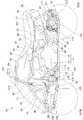
図1は本発明に係るサスペンションアーム支持構造を採用した車両の側面図であり、車両10は、骨格となる車体フレーム11の中央部にエンジン12及びこのエンジン12に一体的に設けられた変速機13からなるパワーユニット14が取付けられ、パワーユニット14の上方に燃料タンク16が配置され、この燃料タンク16の下方で且つラジエータ17とパワーユニット14との間の空間に、燃料タンク16内の燃料をエンジン12に供給する燃料ポンプ18と、パワーユニット14内で使用する潤滑油を貯めるオイルタンク21とが配置され、パワーユニット14の後方にチェーン23を介して動力が伝達される減速装置24が配置され、この減速装置24に左右の後輪26,27を制動するためのディスクブレーキ装置28が付設された不整地走行用四輪車である。The best mode for carrying out the present invention will be described below with reference to the accompanying drawings. The drawings are viewed in the direction of the reference numerals.
FIG. 1 is a side view of a vehicle adopting a suspension arm support structure according to the present invention. A
車体フレーム11は、車体下部を前後方向に延びてパワーユニット14を支持する左右一対のロアメインフレーム31,32(手前側の符号31のみ示す。)と、これらのロアメインフレーム31,32の前端及び後部に取付けられた左右一対のアッパメインフレーム33,34(手前側の符号33のみ示す。)と、これらのアッパメインフレーム33,34の前部からロアメインフレーム31,32の中間部に延びる左右一対のサイドフレーム36,37(手前側の符号36のみ示す。)と、これらのサイドフレーム36,37及びアッパメインフレーム33,34のそれぞれを連結するアッパ補強フレーム41,42(手前側の符号41のみ示す。)と、サイドフレーム36,37及びロアメインフレーム31,32のそれぞれを連結するロア補強フレーム43,44(手前側の符号43のみ示す。)と、アッパメインフレーム33,34の後部上部及びロアメインフレーム31,32の後端のそれぞれに取付けられたリヤアッパフレーム46,47(手前側の符号46のみ示す。)と、これらのリヤアッパフレーム46,47の後端及びロアメインフレーム31,32の後部下部のそれぞれを連結するリヤロアフレーム51,52(手前側の符号51のみ示す。)と、ロアメインフレーム31,32の後部及びリヤアッパフレーム46,47の後端のそれぞれに取付けられたリヤサブフレーム53,54(手前側の符号53のみ示す。)とを備える。 The
エンジン12は、上方に突出するシリンダ部65にシリンダヘッド66を備え、このシリンダヘッド66に吸気装置67及び排気装置68を取付けたものである。なお、71はエンジン12に備えるクランクシャフトである。 The
吸気装置67は、シリンダヘッド66の後部に取付けられたスロットルボディ74と、このスロットルボディ74にコネクティングチューブ76を介して接続されたエアクリーナ77とからなる。
排気装置68は、シリンダヘッド66に一端が取付けられた排気管81と、この排気管81の他端に接続されたマフラ82とからなる。The
The
変速機13は、後部側部に出力軸85が突出し、この出力軸85にドライブスプロケット86が取付けられたものであり、このドライブスプロケット86と、減速装置24側に設けられたドリブンスプロケット87とにチェーン23が掛けられている。 The
図中の95,96は左右一対の前輪、97は前輪95,96を操舵するために車体フレーム11に回転自在に取付けられたステアリングシャフト、101はステアリングシャフト97の上端に取付けられたバーハンドル、102〜105は前輪95,96用サスペンションアームを取付けるために車体フレーム11にそれぞれ左右一対取付けられたフロントサスペンションアームブラケット、107はシート、111〜113は後輪26,27用サスペンションアーム(詳細は後述する。)を取付けるために車体フレーム11に取付けられたリヤサスペンションアームブラケット、115〜117は燃料用ホース(燃料タンク16から燃料ポンプ18への燃料供給管115、燃料ポンプ18からスロットルボディ74に取付けられた不図示のインジェクタへの燃料供給管116、燃料ポンプ18から燃料タンク16への戻し管117)、118はパワーユニット14の前部を支持するエンジンハンガである。 In the figure, 95 and 96 are a pair of left and right front wheels, 97 is a steering shaft rotatably attached to the
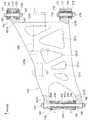
図2は本発明に係る後輪用サスペンションを示す背面図であり、後輪用サスペンション120は、車体フレームを構成するリヤロアフレーム51にフレーム側支持部としてのリヤサスペンションアームブラケット112,113(一方の符号113のみ示す。)を介して上下スイング自在に取付けられたアルミニウム合金製のサスペンションアームとしてのロアアーム121と、車体フレームを構成するリヤサブフレーム53にリヤサスペンションアームブラケット111を介して上下スイング自在の取付けられたアッパアーム122と、上端が車体フレーム上部に取付けられるとともに下端がロアアーム121の中間部連結部121aにスイング自在に連結されたリヤクッションユニット123と、ロアアーム121及びアッパアーム122のそれぞれの先端部に上下スイング自在に連結されたナックル124と、このナックル124にベアリング126を介して回転自在に取付けられたハブ127とからなり、ハブ127に複数のボルト128及びナット129で後輪26が取付けられている。FIG. 2 is a rear view showing a rear wheel suspension according to the present invention. The
ここで、131は減速装置24に設けられ、チェーン23が掛けられたドリブンスプロケット、132は減速装置24の出力軸とハブ127との間に設けられ、減速装置24からハブ127に動力を伝えるドライブシャフト、133は後輪26を構成するホイールである。 Here, 131 is provided in the
図3は本発明に係るロアアーム及びその端部の支持構造を示す説明図(図中の矢印(FRONT)は車両前方を表す。以下同じ。)であり、ロアアーム121は、アルミニウム合金鍛造製、又はアルミニウム合金ダイカスト製で、車体内方側の前部に設けられたアーム側支持部としての内側前部アーム部121Aと、車体内方側の後部に設けられたアーム側支持部としての内側後部アーム部121Bと、車体外方側の前部に設けられた外側前部アーム部121Cと、車体外方側の後部に設けられた外側後部アーム部121Dとをアーム部としてのアーム本体121Eに一体に形成したものである。 FIG. 3 is an explanatory view showing a lower arm and a support structure for the end portion thereof according to the present invention (the arrow (FRONT in the figure indicates the front of the vehicle; the same applies hereinafter)), and the
内側前部アーム部121Aは、リヤサスペンションアームブラケット112に内側前部支持部136を介して支持され、内側後部アーム部121Bは、リヤサスペンションアームブラケット113に内側後部支持部137を介して支持され、外側前部アーム部121C及び外側後部アーム部121Dは、外側支持部138を介してナックル124を支持する。内側前部支持部136及び内側後部支持部137については、図4及び図5で詳述する。なお、121b〜121fは軽量化のための穴部である。 The inner
外側支持部138は、ナックル124に設けられた筒状部141の中空部141aの両端に挿入された鍔付きブッシュ142,142と、これらの鍔付きブッシュ142,142の内側に挿入された筒状のカラー143と、鍔付きブッシュ142,142の半径方向外側で且つ筒状部141の両端部に嵌合されたシール部材144,144と、これらのシール部材144,144のそれぞれに被せられたカップ状の端部カバー部材146,146と、順に外側前部アーム部121C、端部カバー部材146、カラー143、端部カバー部材146、外側後部アーム部121Dを貫通するボルト147と、このボルト147の先端にねじ込まれたナット148とからなる。 The
図4は本発明に係るサスペンションアーム支持構造を示す第1断面図であり、内側前部支持部136を示す。
内側前部支持部136は、内側前部アーム部121Aに前後方向に開けられた貫通穴136aに挿入されたニードルベアリング151と、貫通穴136aの前端部に嵌合するとともに前端面136bに当てられた前ブッシュ152と、貫通穴136aの後端部に圧入されるとともに後端面136cに当てられたブッシュ受け部材153と、このブッシュ受け部材153の大径穴153aに嵌合するとともにブッシュ受け部材153の端面153bに当てられた後ブッシュ154と、これらの前ブッシュ152、ニードルベアリング151、ブッシュ受け部材153、後ブッシュ154のそれぞれの内側に挿入された筒状のカラー156と、前ブッシュ152の外周面152a、及び内側前部アーム部121Aの前端部に一体に形成された円筒部121hの外周面121jのそれぞれに亘って嵌められたシール部材157と、後ブッシュ154の外周面154a、及びブッシュ受け部材153の後端部に一体に形成された円筒部153cの外周面153dのそれぞれに亘って嵌められたシール部材158と、これらのシール部材157,158のそれぞれに被せられたカップ状の端部カバー部材161,161と、順にリヤサスペンションアームブラケット112、端部カバー部材161、カラー156、端部カバー部材161、リヤサスペンションアームブラケット112を貫通するボルト162と、このボルト162の先端にねじ込まれたナット163とからなる。FIG. 4 is a first cross-sectional view showing the suspension arm support structure according to the present invention, and shows the inner
The inner
以上の構成により、内側前部アーム部121Aは、リヤサスペンションアームブラケット112に対して、内側前部支持部136のニードルベアリング151によってニードルベアリング151の半径方向(径方向)に支持され、内側前部支持部136の前ブッシュ152及び後ブッシュ154によってボルト162の軸線162Aが延びる方向、即ち、ボルト162の軸線方向に支持されている。 With the above configuration, the inner
ブッシュ受け部材153は、その中空穴153fの内径がカラー156の外径よりも大きく、カラー156との間に隙間を有するため、カラー156とは摺動しない。 The
このように、ブッシュ受け部材153を設けるのは、内側前部アーム部121Aの前端面136bを加工で形成するのと同様に、内側前部アーム部121Aの後端面136cを加工で形成しようとしても、図3に示したように、内側前部アーム部121Aと内側後部アーム部121Bとを結ぶ線上に後端面136cを加工するための工具が入らない。 As described above, the
代わりに、後ブッシュ154を軸線方向に受けるための端面を、内側前部アーム部121Aとは別体のブッシュ受け部材153に端面153bとして加工で形成している。 Instead, an end surface for receiving the
また、シール部材157を嵌めるために内側前部アーム部121Aの前端部に円筒部121hを加工で形成するのと同様に、内側前部アーム部121Aの後端部に円筒部を加工で形成しようとしても、上記の理由により加工できないため、代わりに、ブッシュ受け部材153の後端部にシール部材158を嵌めるための円筒部153cを加工で形成している。 Further, in order to fit the
図5は本発明に係るサスペンションアーム支持構造を示す第2断面図であり、内側後部支持部137を示す。
内側後部支持部137は、内側後部アーム部121Bに前後方向に開けられた貫通穴137aに挿入されたニードルベアリング171及びシール部材172,172と、これらのニードルベアリング171及びシール部材172,172に挿入された筒状のカラー173と、順にリヤサスペンションアームブラケット113、カラー173、リヤサスペンションアームブラケット113を貫通するボルト174と、このボルト174の先端にねじ込まれたナット176とからなる。FIG. 5 is a second cross-sectional view showing the suspension arm support structure according to the present invention, and shows the inner
The inner
以上の構成により、内側後部アーム部121Bは、リヤサスペンションアームブラケット113に対して、内側後部支持部137のニードルベアリング171によってニードルベアリング171の半径方向(径方向)に支持されているだけで、例えば、ボルト174の軸線174Aの延びる方向、即ち、ボルト174の軸線方向には支持されていない。 With the above configuration, the inner
このように、内側後部アーム部121Bを半径方向にのみ支持することで、図3において、内側前部アーム部121Aと内側後部アーム部121Bとの間隔が製造誤差の範囲内で大きく変化しても、リヤサスペンションアームブラケット112,113にロアアーム121を組付ける場合に、内側後部アーム部121Bが所定位置に対して前後にずれて、上記の製造誤差が吸収され、内側前部アーム部121A及び内側後部アーム部121Bに無理な力が加わることを防止することができる。 Thus, by supporting the inner
図6は本発明に係るサスペンションアーム支持構造の別実施形態を示す断面図であり、車体フレームにリヤサスペンションアームブラケット181が設けられ、このリヤサスペンションアームブラケット181の前後に前部ブラケット部181a、後部ブラケット部181bがそれぞれ設けられ、これらの前部ブラケット部181a及び後部ブラケット部181bにロアアーム121が内側前部支持部183及び内側後部支持部137で支持されている。 FIG. 6 is a cross-sectional view showing another embodiment of the suspension arm support structure according to the present invention. A rear
内側前部支持部183は、内側前部アーム部121Aに前後方向に開けられた貫通穴183aに挿入された球面滑り軸受185と、この球面滑り軸受185を貫通穴183a内に固定するために貫通穴183aの内周面に取付けられた一対の止め輪186,186と、貫通穴183aの両端部に嵌合されたシール部材187,187と、これらのシール部材187,187のそれぞれの内側に挿入されるとともに先端が球面滑り軸受185に当てられた鍔付きスリーブ188,188と、順に前部ブラケット部181a、鍔付きスリーブ188、球面滑り軸受185、鍔付きスリーブ188、前部ブラケット部181aを貫通する六角穴付きボルト191と、この六角穴付きボルト191の先端にねじ込まれたナット192とからなる。The inner
球面滑り軸受185は、貫通穴183aに嵌合する外輪195と、この外輪195に形成された凸状の球面に滑り自在に嵌合する凹状の球面を備え、六角穴付きボルト191に嵌合された内輪196とからなる。 The spherical plain bearing 185 includes an
以上の構成により、内側前部アーム部121Aは、前部ブラケット部181aに対して、内側前部支持部183の球面滑り軸受185によって球面滑り軸受185の半径方向及びボルト191の軸線191Aの延びる方向、即ち、ボルト191の軸線方向に支持されている。 With the above configuration, the inner
尚、本実施形態では、図3に示したように、内側前部アーム部121Aを径方向及び軸線方向に支持し、内側後部アーム部121Bを径方向にのみ支持したが、これに限らず、内側前部アーム部121Aを径方向にのみ支持し、内側後部アーム部121Bを径方向及び軸線方向に支持してもよい。 In the present embodiment, as shown in FIG. 3, the inner
本発明のサスペンションアーム支持構造は、四輪車に好適である。 The suspension arm support structure of the present invention is suitable for a four-wheeled vehicle.
10…車両、11…車体フレーム、112,113…フレーム側支持部(リヤサスペンションアームブラケット)、121…サスペンションアーム(ロアアーム)、121A,121B…アーム側支持部(内側前部アーム部、内側後部アーム部)、121E…アーム部(アーム本体)、136…内側前部支持部、136a…貫通穴、136b…前端面、136c…後端面、137…内側後部支持部、137a…貫通穴、151,171…ニードルベアリング、152,154…ブッシュ(前ブッシュ、後ブッシュ)、153…ブッシュ受け部材、153b…端面、153c…円筒部、153f…中空穴、156…筒状のカラー、158…シール材、162,174…ボルト、162A,174A…ボルトの軸線、185…球面滑り軸受。DESCRIPTION OF
Claims (3)
Translated fromJapanese前記サスペンションアーム(121)は、前記アーム側支持部(121A,121B)と前記アーム部(121E)とが一体成形されるとともに、
前記アーム側支持部の一方である内側前部支持部(136)は、内側前部アーム部(121A)に前後方向に開けられた貫通穴(136a)に挿入されたニードルベアリング(151)と、この貫通穴(136a)の前端部に嵌合するとともに前端面(136b)に当てられた前ブッシュ(152)と、この貫通穴(136a)の後端部に圧入され、且つ後端面(136c)に当てられたブッシュ受け部材(153)と、このブッシュ受け部材(153)の大径穴(153a)に嵌合し、且つこのブッシュ受け部材(153)の端面(153b)に当てられた後ブッシュ(154)とからなり、
前記内側前部支持部(136)は、車体側のフレーム側支持部である前側リヤサスペンションアームブラケット(112)に対し、ニードルベアリング(151)によって半径方向に支持され、前ブッシュ(152)及び後ブッシュ(154)によって前記ボルト(162)の軸線(162A)が延びるボルト(162)の軸線方向に支持され、
前記ブッシュ受け部材(153)は、その中空穴(153f)の内径が、前ブッシュ(152)、ニードルベアリング(151)、ブッシュ受け部材(153)、後ブッシュ(154)のそれぞれの内側に挿入されたボルト(162)を通す筒状のカラー(156)の外径よりも大きく、この筒状のカラー(156)との間に隙間を有し、後ブッシュ(154)を軸線(162A)方向に受けるための端面(153b)を形成しており、
前記アーム側支持部の他方である前記内側後部支持部(137)は、車体側のフレーム側支持部である後側リヤサスペンションアームブラケット(113)に対し内側後部アーム部(121B)前後方向に開けられた貫通穴(137a)に挿入されたニードルベアリング(171)からなり、
内側後部支持部(137)は、リヤサスペンションアームブラケット(113)に対して、前記ニードルベアリング(171)によってニードルベアリング(171)の径方向にのみ支持されている、
ことを特徴とする車両のサスペンション構造。Thefront and rear frame side support portions provided on the vehicle body frame are provided with a pair of arm side support portions supportedvia bolts (162, 174) disposed facing the front and rear direction , and these arm side support portions In the suspension arm support structure in which the arm portion is provided in the
In the suspension arm(121) , the arm side support portion(121A, 121B) and the arm portion(121E) are integrally formed,
Aninner front support part (136) whichis one of the arm side support parts,a needle bearing (151) inserted into a through hole (136a) opened in the front-rear direction in the inner front arm part (121A), The front bushing (152) that is fitted to the front end portion of the through hole (136a) and pressed against the front end surface (136b), and is press-fitted into the rear end portion of the through hole (136a), and the rear end surface (136c) The bush receiving member (153) applied to the bushing and the bush receiving member (153) after being fitted into the large diameter hole (153a) and applied to the end surface (153b) of the bush receiving member (153) (154)
Theinner front support portion (136) is supported in a radial direction by a needle bearing (151) with respect to a front rear suspension arm bracket (112) which is a frame side support portion on the vehicle body side, and includes a front bush (152) and a rear The bush (154) is supported in the axial direction of the bolt (162) in which the axis (162A) of the bolt (162) extends,
The bush receiving member (153) has an inner diameter of the hollow hole (153f) inserted into each of the front bush (152), needle bearing (151), bush receiving member (153), and rear bush (154). Larger than the outer diameter of the cylindrical collar (156) through which the bolt (162) is passed, there is a gap between the cylindrical collar (156) and the rear bush (154) in the direction of the axis (162A). An end face (153b) for receiving,
The inner rear support portion (137) which is the other of the arm side support portions is opened in the front-rear direction of the inner rear arm portion (121B) with respect to the rear rear suspension arm bracket (113) which is a frame side support portion on the vehicle body side. A needle bearing (171) inserted into the through hole (137a) formed,
The inner rear support portion (137) is supported only in the radial direction of the needle bearing (171) by the needle bearing (171) with respect to the rear suspension arm bracket (113).
A suspension structure for a vehicle.
Priority Applications (3)
| Application Number | Priority Date | Filing Date | Title |
|---|---|---|---|
| JP2007092804AJP4825715B2 (en) | 2007-03-30 | 2007-03-30 | Suspension arm support structure |
| AU2008200862AAU2008200862B2 (en) | 2007-03-30 | 2008-02-22 | Suspension arm supporting structure |
| US12/055,060US7857334B2 (en) | 2007-03-30 | 2008-03-25 | Suspension arm supporting structure |
Applications Claiming Priority (1)
| Application Number | Priority Date | Filing Date | Title |
|---|---|---|---|
| JP2007092804AJP4825715B2 (en) | 2007-03-30 | 2007-03-30 | Suspension arm support structure |
Publications (2)
| Publication Number | Publication Date |
|---|---|
| JP2008247263A JP2008247263A (en) | 2008-10-16 |
| JP4825715B2true JP4825715B2 (en) | 2011-11-30 |
Family
ID=39792933
Family Applications (1)
| Application Number | Title | Priority Date | Filing Date |
|---|---|---|---|
| JP2007092804AExpired - Fee RelatedJP4825715B2 (en) | 2007-03-30 | 2007-03-30 | Suspension arm support structure |
Country Status (3)
| Country | Link |
|---|---|
| US (1) | US7857334B2 (en) |
| JP (1) | JP4825715B2 (en) |
| AU (1) | AU2008200862B2 (en) |
Families Citing this family (12)
| Publication number | Priority date | Publication date | Assignee | Title |
|---|---|---|---|---|
| US8091657B2 (en)* | 2007-05-16 | 2012-01-10 | Polaris Industries Inc. | Frame for an all terrain vehicle |
| ES1073337Y (en)* | 2010-09-15 | 2011-03-03 | Jane Sa | SUSPENSION FOR CHILDREN'S CARS |
| KR101416362B1 (en)* | 2012-11-15 | 2014-08-07 | 현대자동차 주식회사 | Energy regeneration device of suspension system for vehicle |
| JPWO2014192081A1 (en)* | 2013-05-28 | 2017-02-23 | 東レ株式会社 | LINK PARTS FOR VEHICLE AND MANUFACTURING METHOD THEREOF |
| JP6241998B2 (en)* | 2014-01-24 | 2017-12-06 | 本田技研工業株式会社 | Vehicle shaft support structure and vehicle |
| MX2017014403A (en)* | 2015-05-15 | 2018-04-11 | Polaris Inc | UTILITY VEHICLE. |
| US10946736B2 (en) | 2018-06-05 | 2021-03-16 | Polaris Industries Inc. | All-terrain vehicle |
| MX2021012802A (en) | 2019-04-30 | 2021-11-12 | Polaris Inc | VEHICLE. |
| US12187127B2 (en) | 2020-05-15 | 2025-01-07 | Polaris Industries Inc. | Off-road vehicle |
| US11691674B2 (en) | 2020-05-15 | 2023-07-04 | Polaris Industries Inc. | Off-road vehicle |
| MX2023006716A (en) | 2022-06-13 | 2023-12-14 | Polaris Inc | POWER TRAIN FOR UTILITY VEHICLE. |
| DE102023135836A1 (en)* | 2023-12-19 | 2025-06-26 | Bayerische Motoren Werke Aktiengesellschaft | Wheel suspension for a vehicle wheel of a motor vehicle and motor vehicles |
Family Cites Families (15)
| Publication number | Priority date | Publication date | Assignee | Title |
|---|---|---|---|---|
| DE1630095A1 (en)* | 1967-08-01 | 1971-04-15 | Daimler Benz Ag | Storage of suspension arms on motor vehicles |
| FR2250399A5 (en) | 1973-10-31 | 1975-05-30 | Citroen Sa | |
| JPS62191207A (en) | 1986-02-17 | 1987-08-21 | Toyota Motor Corp | Automobile rear wheel suspension system |
| US5016903A (en)* | 1989-05-29 | 1991-05-21 | Mazda Motor Corporation | Vehicle suspension system |
| FR2673560B1 (en) | 1991-03-08 | 1995-05-19 | Peugeot | METHOD FOR MANUFACTURING AN ARTICULATION BETWEEN TWO ELEMENTS WITH INTERPOSED BEARING, AND ARTICULATION OBTAINED BY THIS PROCESS. |
| JPH0518411A (en)* | 1991-07-11 | 1993-01-26 | Somitsuku Ishikawa:Kk | Spherical surface slide bearing |
| JP2973050B2 (en)* | 1991-12-11 | 1999-11-08 | 本田技研工業株式会社 | Automotive suspension arm |
| US5993065A (en)* | 1998-07-13 | 1999-11-30 | Chrysler Corporation | Universal slider bushing |
| US6186668B1 (en)* | 1999-02-08 | 2001-02-13 | The Torrington Company | Bearing assembly |
| JP4031917B2 (en)* | 2001-06-20 | 2008-01-09 | 本田技研工業株式会社 | Suspension structure |
| JP4052569B2 (en)* | 2002-11-06 | 2008-02-27 | 本田技研工業株式会社 | Suspension arm mounting structure |
| JP4202791B2 (en) | 2003-03-12 | 2008-12-24 | 本田技研工業株式会社 | Body frame structure of rough terrain vehicle |
| JP4786920B2 (en)* | 2005-03-23 | 2011-10-05 | 本田技研工業株式会社 | Vehicle pivot shaft support structure |
| CA2541040C (en)* | 2005-03-29 | 2009-09-15 | Honda Motor Co., Ltd. | Cushion mounting structure of saddle-ride vehicle |
| JP4662041B2 (en)* | 2005-07-19 | 2011-03-30 | 川崎重工業株式会社 | Vehicle swing arm mounting structure |
- 2007
- 2007-03-30JPJP2007092804Apatent/JP4825715B2/ennot_activeExpired - Fee Related
- 2008
- 2008-02-22AUAU2008200862Apatent/AU2008200862B2/ennot_activeCeased
- 2008-03-25USUS12/055,060patent/US7857334B2/ennot_activeExpired - Fee Related
Also Published As
| Publication number | Publication date |
|---|---|
| JP2008247263A (en) | 2008-10-16 |
| AU2008200862A1 (en) | 2008-10-16 |
| US7857334B2 (en) | 2010-12-28 |
| AU2008200862B2 (en) | 2010-07-29 |
| US20080238014A1 (en) | 2008-10-02 |
Similar Documents
| Publication | Publication Date | Title |
|---|---|---|
| JP4825715B2 (en) | Suspension arm support structure | |
| JP4837531B2 (en) | Rear wheel suspension structure | |
| JP4829641B2 (en) | Motorcycle | |
| CN102562246B (en) | Muffler mounting structure of vehicle and straddle-type four-wheeled vehicle provided with the same | |
| JP2011143835A (en) | Vehicle | |
| JP4516502B2 (en) | Battery arrangement structure for rough terrain vehicle | |
| JP2011143837A (en) | Off-road traveling vehicle | |
| CN101472787B (en) | Straddle type wheeled vehicle and its frame | |
| JP2009228852A (en) | Shaft driving device | |
| JP4814739B2 (en) | Motorcycle | |
| US8381863B2 (en) | Connection structure arrangement between a frame member and an engine of a saddle-type vehicle, and vehicle incorporating same | |
| JP4271641B2 (en) | How to replace the rear part of the body frame | |
| JP2006281839A (en) | Saddle riding vehicle | |
| JP4755505B2 (en) | Arrangement structure of vehicle fuel pump | |
| US7748491B2 (en) | Power transmission structure | |
| JP5665646B2 (en) | Vehicle wheel | |
| JP4881685B2 (en) | Motorcycle | |
| JP2007196972A (en) | Motorcycle | |
| EP2927021B2 (en) | Wheel support mechanism | |
| JP5086155B2 (en) | Front wheel suspension structure for small vehicles | |
| JP6094874B2 (en) | Saddle riding | |
| JP4820252B2 (en) | Motorcycle | |
| JP6134243B2 (en) | Suspension structure for saddle riding type vehicles | |
| JP2009241874A (en) | Front wheel suspension structure of small vehicle | |
| JPH11105769A (en) | Disc brake device for motorcycle |
Legal Events
| Date | Code | Title | Description |
|---|---|---|---|
| A621 | Written request for application examination | Free format text:JAPANESE INTERMEDIATE CODE: A621 Effective date:20091126 | |
| A131 | Notification of reasons for refusal | Free format text:JAPANESE INTERMEDIATE CODE: A131 Effective date:20110614 | |
| A977 | Report on retrieval | Free format text:JAPANESE INTERMEDIATE CODE: A971007 Effective date:20110616 | |
| A521 | Request for written amendment filed | Free format text:JAPANESE INTERMEDIATE CODE: A523 Effective date:20110804 | |
| TRDD | Decision of grant or rejection written | ||
| A01 | Written decision to grant a patent or to grant a registration (utility model) | Free format text:JAPANESE INTERMEDIATE CODE: A01 Effective date:20110906 | |
| A01 | Written decision to grant a patent or to grant a registration (utility model) | Free format text:JAPANESE INTERMEDIATE CODE: A01 | |
| A61 | First payment of annual fees (during grant procedure) | Free format text:JAPANESE INTERMEDIATE CODE: A61 Effective date:20110912 | |
| R150 | Certificate of patent or registration of utility model | Ref document number:4825715 Country of ref document:JP Free format text:JAPANESE INTERMEDIATE CODE: R150 Free format text:JAPANESE INTERMEDIATE CODE: R150 | |
| FPAY | Renewal fee payment (event date is renewal date of database) | Free format text:PAYMENT UNTIL: 20140916 Year of fee payment:3 | |
| LAPS | Cancellation because of no payment of annual fees |