JP4825671B2 - Method for shutting down fuel cell stack and fuel cell system - Google Patents
Method for shutting down fuel cell stack and fuel cell systemDownload PDFInfo
- Publication number
- JP4825671B2 JP4825671B2JP2006526384AJP2006526384AJP4825671B2JP 4825671 B2JP4825671 B2JP 4825671B2JP 2006526384 AJP2006526384 AJP 2006526384AJP 2006526384 AJP2006526384 AJP 2006526384AJP 4825671 B2JP4825671 B2JP 4825671B2
- Authority
- JP
- Japan
- Prior art keywords
- stack
- fuel cell
- temperature
- cooling period
- flow field
- Prior art date
- Legal status (The legal status is an assumption and is not a legal conclusion. Google has not performed a legal analysis and makes no representation as to the accuracy of the status listed.)
- Expired - Lifetime
Links
- 239000000446fuelSubstances0.000titleclaimsdescription85
- 238000000034methodMethods0.000titleclaimsdescription42
- 238000001816coolingMethods0.000claimsdescription61
- 239000000376reactantSubstances0.000claimsdescription18
- 239000002826coolantSubstances0.000claimsdescription15
- 239000005518polymer electrolyteSubstances0.000claimsdescription11
- 239000007787solidSubstances0.000claimsdescription11
- 238000010438heat treatmentMethods0.000claimsdescription7
- 230000007423decreaseEffects0.000claimsdescription6
- 238000010248power generationMethods0.000claimsdescription5
- XLYOFNOQVPJJNP-UHFFFAOYSA-NwaterSubstancesOXLYOFNOQVPJJNP-UHFFFAOYSA-N0.000description68
- 239000012528membraneSubstances0.000description20
- 239000003054catalystSubstances0.000description13
- 239000003792electrolyteSubstances0.000description13
- 238000009792diffusion processMethods0.000description10
- 239000007789gasSubstances0.000description9
- 239000007788liquidSubstances0.000description9
- BASFCYQUMIYNBI-UHFFFAOYSA-NplatinumChemical compound[Pt]BASFCYQUMIYNBI-UHFFFAOYSA-N0.000description5
- OKTJSMMVPCPJKN-UHFFFAOYSA-NCarbonChemical compound[C]OKTJSMMVPCPJKN-UHFFFAOYSA-N0.000description4
- 230000003247decreasing effectEffects0.000description4
- 238000007710freezingMethods0.000description4
- 230000008014freezingEffects0.000description4
- 238000012546transferMethods0.000description4
- UFHFLCQGNIYNRP-UHFFFAOYSA-NHydrogenChemical compound[H][H]UFHFLCQGNIYNRP-UHFFFAOYSA-N0.000description3
- 238000013459approachMethods0.000description3
- 230000008901benefitEffects0.000description3
- 239000012530fluidSubstances0.000description3
- 229910052739hydrogenInorganic materials0.000description3
- 239000001257hydrogenSubstances0.000description3
- 238000009413insulationMethods0.000description3
- 238000005259measurementMethods0.000description3
- 238000010926purgeMethods0.000description3
- 239000000758substrateSubstances0.000description3
- 229920000557Nafion®Polymers0.000description2
- 238000009825accumulationMethods0.000description2
- 230000000903blocking effectEffects0.000description2
- 229910052799carbonInorganic materials0.000description2
- 239000007795chemical reaction productSubstances0.000description2
- 238000007796conventional methodMethods0.000description2
- 238000005260corrosionMethods0.000description2
- 230000007797corrosionEffects0.000description2
- 238000013461designMethods0.000description2
- 239000000463materialSubstances0.000description2
- 239000000203mixtureSubstances0.000description2
- 238000012986modificationMethods0.000description2
- 230000004048modificationEffects0.000description2
- 239000007800oxidant agentSubstances0.000description2
- 230000001590oxidative effectEffects0.000description2
- 229920001343polytetrafluoroethylenePolymers0.000description2
- 239000004810polytetrafluoroethyleneSubstances0.000description2
- 238000012360testing methodMethods0.000description2
- 229920000049Carbon (fiber)Polymers0.000description1
- 229910001260Pt alloyInorganic materials0.000description1
- 230000002411adverseEffects0.000description1
- 239000006227byproductSubstances0.000description1
- 239000003990capacitorSubstances0.000description1
- 239000006229carbon blackSubstances0.000description1
- 239000004917carbon fiberSubstances0.000description1
- 230000008859changeEffects0.000description1
- 238000006243chemical reactionMethods0.000description1
- 239000013626chemical specieSubstances0.000description1
- 230000000052comparative effectEffects0.000description1
- 230000006835compressionEffects0.000description1
- 238000007906compressionMethods0.000description1
- 238000011161developmentMethods0.000description1
- 238000010586diagramMethods0.000description1
- 238000004821distillationMethods0.000description1
- 238000005485electric heatingMethods0.000description1
- 238000003487electrochemical reactionMethods0.000description1
- 230000007613environmental effectEffects0.000description1
- 238000001704evaporationMethods0.000description1
- 230000008020evaporationEffects0.000description1
- UQSQSQZYBQSBJZ-UHFFFAOYSA-Nfluorosulfonic acidChemical compoundOS(F)(=O)=OUQSQSQZYBQSBJZ-UHFFFAOYSA-N0.000description1
- 239000006260foamSubstances0.000description1
- 229910002804graphiteInorganic materials0.000description1
- 239000010439graphiteSubstances0.000description1
- 230000036571hydrationEffects0.000description1
- 238000006703hydration reactionMethods0.000description1
- 239000011261inert gasSubstances0.000description1
- 239000003014ion exchange membraneSubstances0.000description1
- 229920000554ionomerPolymers0.000description1
- 238000012423maintenanceMethods0.000description1
- 230000007246mechanismEffects0.000description1
- VNWKTOKETHGBQD-UHFFFAOYSA-NmethaneChemical compoundCVNWKTOKETHGBQD-UHFFFAOYSA-N0.000description1
- 229910000510noble metalInorganic materials0.000description1
- 239000002245particleSubstances0.000description1
- 229910052697platinumInorganic materials0.000description1
- -1polytetrafluoroethylenePolymers0.000description1
- 238000012545processingMethods0.000description1
- 238000000926separation methodMethods0.000description1
- 230000000007visual effectEffects0.000description1
Images


Classifications
- H—ELECTRICITY
- H01—ELECTRIC ELEMENTS
- H01M—PROCESSES OR MEANS, e.g. BATTERIES, FOR THE DIRECT CONVERSION OF CHEMICAL ENERGY INTO ELECTRICAL ENERGY
- H01M8/00—Fuel cells; Manufacture thereof
- H01M8/04—Auxiliary arrangements, e.g. for control of pressure or for circulation of fluids
- H01M8/04082—Arrangements for control of reactant parameters, e.g. pressure or concentration
- H01M8/04089—Arrangements for control of reactant parameters, e.g. pressure or concentration of gaseous reactants
- H01M8/04119—Arrangements for control of reactant parameters, e.g. pressure or concentration of gaseous reactants with simultaneous supply or evacuation of electrolyte; Humidifying or dehumidifying
- H01M8/04156—Arrangements for control of reactant parameters, e.g. pressure or concentration of gaseous reactants with simultaneous supply or evacuation of electrolyte; Humidifying or dehumidifying with product water removal
- H—ELECTRICITY
- H01—ELECTRIC ELEMENTS
- H01M—PROCESSES OR MEANS, e.g. BATTERIES, FOR THE DIRECT CONVERSION OF CHEMICAL ENERGY INTO ELECTRICAL ENERGY
- H01M8/00—Fuel cells; Manufacture thereof
- H01M8/04—Auxiliary arrangements, e.g. for control of pressure or for circulation of fluids
- H—ELECTRICITY
- H01—ELECTRIC ELEMENTS
- H01M—PROCESSES OR MEANS, e.g. BATTERIES, FOR THE DIRECT CONVERSION OF CHEMICAL ENERGY INTO ELECTRICAL ENERGY
- H01M8/00—Fuel cells; Manufacture thereof
- H01M8/04—Auxiliary arrangements, e.g. for control of pressure or for circulation of fluids
- H01M8/04223—Auxiliary arrangements, e.g. for control of pressure or for circulation of fluids during start-up or shut-down; Depolarisation or activation, e.g. purging; Means for short-circuiting defective fuel cells
- H01M8/04228—Auxiliary arrangements, e.g. for control of pressure or for circulation of fluids during start-up or shut-down; Depolarisation or activation, e.g. purging; Means for short-circuiting defective fuel cells during shut-down
- H—ELECTRICITY
- H01—ELECTRIC ELEMENTS
- H01M—PROCESSES OR MEANS, e.g. BATTERIES, FOR THE DIRECT CONVERSION OF CHEMICAL ENERGY INTO ELECTRICAL ENERGY
- H01M8/00—Fuel cells; Manufacture thereof
- H01M8/02—Details
- H—ELECTRICITY
- H01—ELECTRIC ELEMENTS
- H01M—PROCESSES OR MEANS, e.g. BATTERIES, FOR THE DIRECT CONVERSION OF CHEMICAL ENERGY INTO ELECTRICAL ENERGY
- H01M8/00—Fuel cells; Manufacture thereof
- H01M8/02—Details
- H01M8/0202—Collectors; Separators, e.g. bipolar separators; Interconnectors
- H01M8/0258—Collectors; Separators, e.g. bipolar separators; Interconnectors characterised by the configuration of channels, e.g. by the flow field of the reactant or coolant
- H—ELECTRICITY
- H01—ELECTRIC ELEMENTS
- H01M—PROCESSES OR MEANS, e.g. BATTERIES, FOR THE DIRECT CONVERSION OF CHEMICAL ENERGY INTO ELECTRICAL ENERGY
- H01M8/00—Fuel cells; Manufacture thereof
- H01M8/02—Details
- H01M8/0202—Collectors; Separators, e.g. bipolar separators; Interconnectors
- H01M8/0267—Collectors; Separators, e.g. bipolar separators; Interconnectors having heating or cooling means, e.g. heaters or coolant flow channels
- H—ELECTRICITY
- H01—ELECTRIC ELEMENTS
- H01M—PROCESSES OR MEANS, e.g. BATTERIES, FOR THE DIRECT CONVERSION OF CHEMICAL ENERGY INTO ELECTRICAL ENERGY
- H01M8/00—Fuel cells; Manufacture thereof
- H01M8/04—Auxiliary arrangements, e.g. for control of pressure or for circulation of fluids
- H01M8/04007—Auxiliary arrangements, e.g. for control of pressure or for circulation of fluids related to heat exchange
- H01M8/04037—Electrical heating
- H—ELECTRICITY
- H01—ELECTRIC ELEMENTS
- H01M—PROCESSES OR MEANS, e.g. BATTERIES, FOR THE DIRECT CONVERSION OF CHEMICAL ENERGY INTO ELECTRICAL ENERGY
- H01M8/00—Fuel cells; Manufacture thereof
- H01M8/04—Auxiliary arrangements, e.g. for control of pressure or for circulation of fluids
- H01M8/04007—Auxiliary arrangements, e.g. for control of pressure or for circulation of fluids related to heat exchange
- H01M8/04067—Heat exchange or temperature measuring elements, thermal insulation, e.g. heat pipes, heat pumps, fins
- H01M8/04074—Heat exchange unit structures specially adapted for fuel cell
- H—ELECTRICITY
- H01—ELECTRIC ELEMENTS
- H01M—PROCESSES OR MEANS, e.g. BATTERIES, FOR THE DIRECT CONVERSION OF CHEMICAL ENERGY INTO ELECTRICAL ENERGY
- H01M8/00—Fuel cells; Manufacture thereof
- H01M8/04—Auxiliary arrangements, e.g. for control of pressure or for circulation of fluids
- H01M8/04298—Processes for controlling fuel cells or fuel cell systems
- H01M8/043—Processes for controlling fuel cells or fuel cell systems applied during specific periods
- H01M8/04303—Processes for controlling fuel cells or fuel cell systems applied during specific periods applied during shut-down
- H—ELECTRICITY
- H01—ELECTRIC ELEMENTS
- H01M—PROCESSES OR MEANS, e.g. BATTERIES, FOR THE DIRECT CONVERSION OF CHEMICAL ENERGY INTO ELECTRICAL ENERGY
- H01M8/00—Fuel cells; Manufacture thereof
- H01M8/24—Grouping of fuel cells, e.g. stacking of fuel cells
- H01M8/241—Grouping of fuel cells, e.g. stacking of fuel cells with solid or matrix-supported electrolytes
- H—ELECTRICITY
- H01—ELECTRIC ELEMENTS
- H01M—PROCESSES OR MEANS, e.g. BATTERIES, FOR THE DIRECT CONVERSION OF CHEMICAL ENERGY INTO ELECTRICAL ENERGY
- H01M8/00—Fuel cells; Manufacture thereof
- H01M8/24—Grouping of fuel cells, e.g. stacking of fuel cells
- H01M8/2465—Details of groupings of fuel cells
- H—ELECTRICITY
- H01—ELECTRIC ELEMENTS
- H01M—PROCESSES OR MEANS, e.g. BATTERIES, FOR THE DIRECT CONVERSION OF CHEMICAL ENERGY INTO ELECTRICAL ENERGY
- H01M8/00—Fuel cells; Manufacture thereof
- H01M8/04—Auxiliary arrangements, e.g. for control of pressure or for circulation of fluids
- H01M8/04223—Auxiliary arrangements, e.g. for control of pressure or for circulation of fluids during start-up or shut-down; Depolarisation or activation, e.g. purging; Means for short-circuiting defective fuel cells
- H01M8/04225—Auxiliary arrangements, e.g. for control of pressure or for circulation of fluids during start-up or shut-down; Depolarisation or activation, e.g. purging; Means for short-circuiting defective fuel cells during start-up
- Y—GENERAL TAGGING OF NEW TECHNOLOGICAL DEVELOPMENTS; GENERAL TAGGING OF CROSS-SECTIONAL TECHNOLOGIES SPANNING OVER SEVERAL SECTIONS OF THE IPC; TECHNICAL SUBJECTS COVERED BY FORMER USPC CROSS-REFERENCE ART COLLECTIONS [XRACs] AND DIGESTS
- Y02—TECHNOLOGIES OR APPLICATIONS FOR MITIGATION OR ADAPTATION AGAINST CLIMATE CHANGE
- Y02E—REDUCTION OF GREENHOUSE GAS [GHG] EMISSIONS, RELATED TO ENERGY GENERATION, TRANSMISSION OR DISTRIBUTION
- Y02E60/00—Enabling technologies; Technologies with a potential or indirect contribution to GHG emissions mitigation
- Y02E60/30—Hydrogen technology
- Y02E60/50—Fuel cells
Landscapes
- Life Sciences & Earth Sciences (AREA)
- Engineering & Computer Science (AREA)
- Manufacturing & Machinery (AREA)
- Sustainable Development (AREA)
- Sustainable Energy (AREA)
- Chemical & Material Sciences (AREA)
- Chemical Kinetics & Catalysis (AREA)
- Electrochemistry (AREA)
- General Chemical & Material Sciences (AREA)
- Fuel Cell (AREA)
Description
Translated fromJapanese (発明の分野)
本発明は、シャットダウン中における燃料電池直列スタックの電池内の水分布を改善する方法および設計に関する。特に、固体高分子電解質燃料電池スタックのシャットダウンに関する。(Field of Invention)
The present invention relates to a method and design for improving water distribution in a cell of a fuel cell series stack during shutdown. In particular, it relates to the shutdown of a solid polymer electrolyte fuel cell stack.
燃料電池システムは、現在、固定型の発電装置や携帯用発電ユニットとして、幅広く多用なアプリケーションで電力供給に用いるため、開発されてきている。こうしたシステムは、経済的な電力供給を約束するものである一方、環境面でもメリットをもたらす。 Fuel cell systems are currently being developed for use in supplying power in a wide variety of applications as stationary power generation devices and portable power generation units. While these systems promise an economical power supply, they also offer environmental benefits.
燃料電池は、燃料と酸化反応剤とを変換して、発電を行い、反応生成物を発生する。一般的に、燃料電池では、カソードとアノードとの間に配置される電解質が用いられる。典型的には、触媒は、電極にて所望の電気化学反応を引き起こす。 The fuel cell converts fuel and an oxidizing reactant to generate electric power and generate a reaction product. Generally, in a fuel cell, an electrolyte disposed between a cathode and an anode is used. Typically, the catalyst causes the desired electrochemical reaction at the electrode.
燃料電池としては、特に、携帯用や動力用のアプリケーションとして好ましいのは、固体高分子電解質(SPE)膜を備え、比較的低温で動作する固体高分子電解質燃料電池である。 As the fuel cell, a solid polymer electrolyte fuel cell including a solid polymer electrolyte (SPE) membrane and operating at a relatively low temperature is particularly preferable as a portable or power application.
SPE燃料電池は、カソードとアノード間に配された高分子固体電解質またはイオン交換膜を備えた膜電解質接合体(MEA)を用いる。各電極は、固体高分子電解質膜の隣に位置する適切な触媒を備える触媒層を含む。触媒は、典型的には、貴金属組成物(例えば、白金黒あるいは白金の合金)であり、適切な支持材(例えば、カーボンブラック支持材に担持された細かい白金パーティクル)に提供され得る。触媒層は、固体高分子電解質膜(例えば、Nafion(登録商標))に使われているのと同様なアイオノマーを含みうる。さらに、電極は多孔性導電性基板を含むこともあり、これは、機械的支持、電気伝導、および/または、反応剤分布のために使われ、こうして、流体拡散層の役割を果たしうる。反応剤(reactant)が、各電極または各電極基板の表面を横断するように導くフローフィールドプレートは、MEAの両側に配されている。動作にあたっては、荷電時の個々の燃料電池の出力電圧は、一般的に、1ボルト未満である。したがって、出力電圧を大きくするためには、通常は、数多くの燃料電池が集まってスタックされ、直列に繋がれ、高電圧燃料電池スタックを生成する。 An SPE fuel cell uses a membrane electrolyte assembly (MEA) comprising a solid polymer electrolyte or ion exchange membrane disposed between a cathode and an anode. Each electrode includes a catalyst layer with a suitable catalyst located next to the solid polymer electrolyte membrane. The catalyst is typically a noble metal composition (eg, platinum black or an alloy of platinum) and can be provided on a suitable support (eg, fine platinum particles supported on a carbon black support). The catalyst layer can include an ionomer similar to that used in solid polymer electrolyte membranes (eg, Nafion®). In addition, the electrodes may include a porous conductive substrate, which is used for mechanical support, electrical conduction, and / or reactant distribution, and thus can serve as a fluid diffusion layer. A flow field plate that guides the reactants across the surface of each electrode or each electrode substrate is arranged on both sides of the MEA. In operation, the output voltage of an individual fuel cell when charged is generally less than 1 volt. Therefore, in order to increase the output voltage, a large number of fuel cells are usually stacked together and connected in series to generate a high voltage fuel cell stack.
SPE燃料電池の通常の動作中は、燃料は、アノード触媒にて、電気化学的に酸化され、その結果、典型的には、プロトン、電子、そして、おそらく、用いられる燃料によって他の化学種が生成する。プロトンは、そのプロトンの発生した反応場所から、電解質を介し、カソード触媒の酸化剤と電気化学的に反応するように導かれる。電子は、使用可能な電力を供給する外部回路を介して移動し、次いで、カソードにあるプロトンと酸化剤と反応し、水を反応生成物として生成する。 During normal operation of an SPE fuel cell, the fuel is electrochemically oxidized at the anode catalyst so that typically protons, electrons, and possibly other chemical species are present depending on the fuel used. Generate. Protons are led from the reaction site where the protons are generated to electrochemically react with the oxidant of the cathode catalyst via the electrolyte. The electrons travel through an external circuit that supplies usable power and then reacts with the protons and oxidants at the cathode to produce water as a reaction product.
燃料電池のアプリケーションにおいては、電力に対する需要が、本質的に連続的であるため、めったにシャットダウン(例えば、メンテナンスのため)してはいけないものもある。しかしながら、多くのアプリケーション(例えば、自動車)では、燃料電池スタックでは、シャットダウンと再起動とが頻繁にありえ、その間に著しく長い蓄電期間が付き物である。例えば、米国特許出願公開第2002/0076582号および第2002/0076583号において、カソード腐食を招く状態が起動中とシャットダウン中に起こり、適切な流体をアノードフローフィールドに素早く流してパージすることによって、カソード腐食を低減することができることが開示されている。 In fuel cell applications, the demand for electrical power is inherently continuous and therefore rarely should be shut down (eg, for maintenance). However, in many applications (e.g., automobiles), fuel cell stacks can frequently be shut down and restarted, accompanied by a significantly longer storage period. For example, in US Patent Application Publication Nos. 2002/0076582 and 2002/0076583, cathode corrosion conditions occur during start-up and shutdown, and the appropriate fluid is quickly flushed into the anode flow field and purged. It is disclosed that corrosion can be reduced.
その他の問題としては、繰り返し利用から生じるものがあり、これはシャットダウン後のスタック内に残存する水の量と分布(distribution)に関するものである。例えば、スタック内に液体の水が蓄積されるのは、シャットダウン中に、あまりにも多量に残存する水、および/または、望ましからぬ水分布から生じる。このように液体の水が蓄積されると、反応剤および/または副産物の流れがブロックされ、電池性能に悪影響を与える。おそらく、さらに悪いことに、燃料電池スタックが、凍結温度以下で格納されている場合、電池内に蓄積された液体水は凍り、その結果、電池に恒久的なダメージを与えかねない。その一方で、水が全く残っていない場合は、膜電解質の導電性が実質的に低下させ、スタックを再起動するときに、電力能力を低くする結果となる。 Other problems arise from repeated use, which relates to the amount and distribution of water remaining in the stack after shutdown. For example, liquid water accumulation in the stack results from too much water remaining and / or undesired water distribution during shutdown. This accumulation of liquid water blocks reactant and / or byproduct streams and adversely affects battery performance. Perhaps even worse, if the fuel cell stack is stored below the freezing temperature, the liquid water stored in the cell freezes, which can result in permanent damage to the cell. On the other hand, if no water remains, the conductivity of the membrane electrolyte is substantially reduced, resulting in lower power capability when restarting the stack.
こうした困難があるので、技術開発を行って、シャットダウン中と蓄電中における燃料電池スタックの水分布を改善するための手順および/または設計変更することが、依然、必要とされている。本発明は、こうしたニーズなどに取り組むものであり、さらに関連する利点を提供するものである。 Because of these difficulties, there is still a need for technological development to change procedures and / or design changes to improve fuel cell stack water distribution during shutdown and storage. The present invention addresses these needs and provides further related advantages.
(本発明の概要)
燃料電池スタックを、シャットダウンしながら、冷やしていくときに、スタック中の電池に渡って(across)、適切な温度差の維持を確保すれば、シャットダウン後に、望ましい水分布が得られるということが、分かってきた。例えば、このような方法によって、固体高分子電解質燃料電池スタックに残っている水は、より冷たいフローフィールドから選ばれたセットの中に集中され、適切に処理され、その一方で、膜電解質に十分残っている水は、導電性の目的に使われる。(Outline of the present invention)
When the fuel cell stack is cooled down while shutting down, it is possible to obtain a desirable water distribution after shutdown if the appropriate temperature difference is maintained across the cells in the stack. I understand. For example, by such a method, the water remaining in the solid polymer electrolyte fuel cell stack is concentrated in a set selected from a cooler flow field and treated appropriately, while sufficient for the membrane electrolyte. The remaining water is used for conductive purposes.
特に、本発明の方法は、少なくとも2つの燃料電池、典型的には、複数の燃料電池が直列に繋がった燃料電池直列スタックに適用できる。本方法は、特に、固体高分子電解質燃料電池直列スタックに適している。シャットダウン方法は、スタックからの発電を止め、しばらくの間(冷却期間)、制御された方法でスタックを冷却することも含む。その間、温度差が、スタック内の各電池のカソード側とアノード側との間で保たれ、電池のそれぞれにおける温度差の方向は、同じである。すなわち、冷却期間において、各電池でカソードがアノードより温度が高いか、その逆かのいずれかである。このアプローチで、各電池の水は、一般的に、冷却期間中に、冷たい側に流れる。 In particular, the method of the present invention can be applied to at least two fuel cells, typically a fuel cell series stack in which a plurality of fuel cells are connected in series. The method is particularly suitable for solid polymer electrolyte fuel cell series stacks. The shutdown method also includes stopping power generation from the stack and cooling the stack in a controlled manner for a while (cooling period). Meanwhile, a temperature difference is maintained between the cathode side and the anode side of each cell in the stack, and the direction of the temperature difference in each cell is the same. That is, in the cooling period, in each battery, the cathode is either hotter than the anode or vice versa. With this approach, the water in each cell generally flows to the cold side during the cooling period.
適切なシャットダウン方法は、冷却期間中に、各電池内で、同じ絶対温度と温度差とを維持することを含む(例えば、各電池のカソード側温度はほぼ同じで、各電池のアノード側温度はほぼ同じ)。その結果、スタックの両端間の温度プロファイルは、鋸の歯状に似て、個々の電池の温度プロファイルは、一つの歯に相当する。こうしたプロファイルは、スタック内の隣接する燃料電池を断熱すること(例えば、電池の各ペア間の熱抵抗を増やす)、電極の選ばれたセットを徐冷すること(例えば、スタック内の冷却チャネルに隣接する電極のセットを冷やす)で得られる。 A suitable shutdown method includes maintaining the same absolute temperature and temperature differential within each battery during the cooling period (eg, the cathode side temperature of each battery is approximately the same, and the anode side temperature of each battery is almost the same). As a result, the temperature profile between the ends of the stack resembles a sawtooth, and the temperature profile of an individual battery corresponds to one tooth. Such a profile can insulate adjacent fuel cells in the stack (eg, increase the thermal resistance between each pair of cells), or slowly cool a selected set of electrodes (eg, to a cooling channel in the stack). Obtained by cooling a set of adjacent electrodes).
代替のシャットダウン方法としては、冷却期間中に、スタック内の燃料電池グループに渡って、温度を単調な減少を維持することである。つまり、各燃料電池グループは、熱い側と冷たい側を有し、各グループ内の燃料電池の温度は、冷却期間中に、熱い側と冷たい側との間のグループに渡って、単調に減少し、各グループの熱い側と冷たい側との温度と温度差とは、冷却期間中は、実質上、同じである。再び、その結果得られるスタックの両端間の温度プロファイルは、鋸の歯状に似るが、ここでは、個々の電池グループの温度プロファイルは、一つの歯に相当する。このようなプロファイルは、例えば、電池のグループ間に、ペルティエ(Peltier)デバイスを組み込むことで、得られうる。各ペルティエデバイスは、電池グループの「冷たい」側を冷やす役割を果たし、隣接する電池グループの「熱い」側を熱する。 An alternative shutdown method is to maintain a monotonic decrease in temperature across the fuel cell groups in the stack during the cooling period. That is, each fuel cell group has a hot side and a cold side, and the temperature of the fuel cells in each group decreases monotonically over the group between the hot side and the cold side during the cooling period. The temperature and temperature difference between the hot and cold sides of each group are substantially the same during the cooling period. Again, the resulting temperature profile across the stack resembles a sawtooth, but here the temperature profile of an individual cell group corresponds to one tooth. Such a profile can be obtained, for example, by incorporating a Peltier device between groups of batteries. Each Peltier device serves to cool the “cold” side of the battery group and heats the “hot” side of the adjacent battery group.
さらなる代替のシャットダウン方法は、冷却期間中に、スタック全体に渡って温度を単調な減少に維持することを含む。このようなプロファイルは、スタックの「熱い」端を熱すること、あるいは、単にスタックの「熱い」端を断熱して、スタックの「熱い」端を、熱いままに維持することによって得られる。代替的に、スタックの「冷たい」端を適切に冷やすことでも、得られる。 A further alternative shutdown method involves maintaining a monotonically decreasing temperature throughout the stack during the cooling period. Such a profile can be obtained by heating the “hot” end of the stack or simply insulating the “hot” end of the stack and keeping the “hot” end of the stack hot. Alternatively, it can also be obtained by properly cooling the “cold” end of the stack.
シャットダウン前、したがって、冷却期間前、典型的なスタックは、約70℃を超える温度でありうる。冷却期間は、冷たい端で、スタック温度が約40℃未満になるまで続ける必要がありうる。冷却期間中の効果的な温度差は、電池1個当たり、約1℃か1℃より少し大きい程度で、効果的な冷却期間は、約20分以上である。しかしながら、温度差がより小さいこと、および/または、冷却時間がより短いことも、また、効果的であることが期待されうる。 Prior to shutdown, and thus before the cooling period, a typical stack can be at a temperature above about 70 ° C. The cooling period may need to continue at the cold end until the stack temperature is below about 40 ° C. The effective temperature difference during the cooling period is about 1 ° C or slightly larger than 1 ° C per battery, and the effective cooling period is about 20 minutes or more. However, smaller temperature differences and / or shorter cooling times can also be expected to be effective.
典型的なSPEスタック内の燃料電池は、カソード反応剤フローフィールドとアノード反応剤フローフィールドを備え、本方法は、水がいずれのセットのフローフィールド(例えば、カソード側)にも集中されることを可能とする。特定の実施形態と動作条件で、これらの反応剤フローフィールドは、冷却期間中に、望ましくはパージされることも、されないこともある。 A fuel cell in a typical SPE stack includes a cathode reactant flow field and an anode reactant flow field, and the method allows water to be concentrated in either set of flow fields (eg, on the cathode side). Make it possible. Depending on the particular embodiment and operating conditions, these reactant flow fields may or may not be desirably purged during the cooling period.
(発明の詳細な説明)
本発明のシャットダウン方法は、SPE燃料電池スタックの望ましい水分布を得るために、特に有用である。典型的なSPE燃料電池スタックを図1に、模式的に示す。スタック1は、スタック1の正極端と負極端に、それぞれ電池2と電池3とを含むスタック化された複数の電池を備える。両極端との間に、複数の電池4(単純化するために、図1では、両端間には、2つの電池しか描かれていない)を備える。各電池は、固体高分子電解質膜5を含む。適切な触媒層(図示せず)が、各電池のアノードとカソードとして機能し、各膜5の対向する面に適用される。各電池は、アノードガス拡散層6と、カソードガス拡散層7をさらに備える。さらに、各電池のガス拡散層6と7に、それぞれアノードフローフィールドプレート8とカソードフローフィールドプレート9とが隣接している。各プレートはアノードフローフィールドチャネル10とカソードフローフィールドチャネル11とをそれぞれ備える。図示されているように、各アノードフローフィールドプレート8(端にある電池2を除く)は、クーラントフローフィールドチャネル12を含む。典型的には、負と正のバスプレート(図示せず)および一対の圧縮プレート(図示せず)が、スタックの両端に備えられる。流体は、様々なポート(port)やマニフォールド(manifold)(図示せず)を介し、反応剤とクーラントのフローフィールドに/から提供される。(Detailed description of the invention)
The shutdown method of the present invention is particularly useful for obtaining the desired water distribution of the SPE fuel cell stack. A typical SPE fuel cell stack is shown schematically in FIG. The
本発明の方法では、スタックがシャットダウンしたときの冷却期間中に、スタック1の各電池のアノード側とカソード側との間において、温度差が一定に保たれる。図1では、示された温度が、アノードからカソードに向かって下がっている。適切な時間にわたって、この温度差にさらすと、アノード側からカソード側へ行く移動とともに、(蒸留と濃縮のメカニズムによって)各電池内の水が著しく動く。このような温度差では、イオン伝導性を十分なレベルに保つために、十分な水が、電解質膜5に残るものの、移動した水のほとんどは、カソードフローフィールド11に集まる。冷却期間が終われば、スタックは典型的には、雰囲気温度と平衡することが許される。 In the method of the present invention, the temperature difference is kept constant between the anode side and the cathode side of each battery in the
図1および以下の実施例に示すように、水は、シャットダウン中にSPE燃料電池スタックのカソードフローフィールドに集められる。カソード側に集まった水が、カソードフローフィールドをブロックすることなく引き受けられ、かつ、集まった水が蓄電中の凍結に対し問題を起こさないように設計されている場合、これは望ましいことである。カソードフローフィールドは、シャットダウン中に何らかの適切な方法(例えば、不活性ガスによる)で、簡単に排水されるか、あるいは、簡単にパージされるようにし、水を除去することも、望まれうる。しかしながら、構造および/または動作(例えば、アノードパージがシャットダウン中に行われる場合)の違いによって、その代わりに、シャットダウン中にアノード側に水を導き、好まれる温度差を逆にするような他のスタックの実施形態も望まれうる。 As shown in FIG. 1 and the examples below, water is collected in the cathode flow field of the SPE fuel cell stack during shutdown. This is desirable when the water collected on the cathode side is accepted without blocking the cathode flow field and the water collected is designed not to cause problems with freezing during storage. It may also be desirable to allow the cathode flow field to be easily drained or easily purged to remove water in any suitable manner during shutdown (eg, with an inert gas). However, due to differences in structure and / or operation (eg, when the anode purge is performed during shutdown), other such as instead leading water to the anode side during shutdown and reversing the preferred temperature difference Stack embodiments may also be desired.
従来型の燃料電池スタックでは、スタックの端は、スタックの残余部よりも幾分か早く、典型的には冷え、冷却中のスタックに渡る(across)温度プロファイルは、単調ではなく、同方向の各電池内に渡る温度プロファイルも一定ではなかった。こうして、望ましい温度差を得るために、スタック温度が適切に制御されること、あるいは、電池および/またはスタックに変更を加えることが、必須であった。 In conventional fuel cell stacks, the stack edges are somewhat faster than the rest of the stack, typically cool, and the temperature profile across the cooling stack is not monotonous, but in the same direction The temperature profile across each battery was also not constant. Thus, it was essential that the stack temperature be properly controlled or that the battery and / or stack be modified in order to obtain the desired temperature difference.
一実施形態として、冷却期間中、各電池に同じ温度プロファイルが形成される(つまり、各アノードフローフィールドの温度がほぼ同じで、各カソードフローフィールドの温度も同様である)。例えば、シャットダウン中に、クーラントチャネル12内にあるクーラントを使って、各アノードフローフィールドプレート8より、各カソードフローフィールドプレート9を少し多めに冷やすことで、これは達成されうる。スタックの代表的に「熱い」部分は、モニターされ、制御して、流れているクーラントの温度を適切に下げて、アノードフローフィールドプレート8がカソードフローフィールドプレート9より、常に少し熱い程度になるようにするために使われる。 In one embodiment, the same temperature profile is formed for each cell during the cooling period (ie, the temperature of each anode flow field is approximately the same, and the temperature of each cathode flow field is similar). For example, this can be accomplished by cooling each cathode flow field plate 9 a little more than each anode
隣り合うアノードフローフィールドチャネル10とカソードフローフィールドチャネル11の間が、望まれる温度差となるようにするためには、各対となっている電池に、熱抵抗を増やす必要がある。図1で、アノードフローフィールドチャネル10をクーラントチャネル12から分離する平面領域13にあるアノードフローフィールドプレート8を変更することで、熱抵抗は増える。変更には、チャネル10をチャネル12からの分離を増やすこと、領域13の絶縁ボイドを導入すること、領域13でプレート8の残部より熱抵抗の大きな別の材料を使うことを含む。代替として、プレート8の残部より熱抵抗の大きな別の材料でできた断熱性ライナー(liner)14をクーラントチャネル12側に裏打ちすることで、熱抵抗は、増やせる。いずれの方法でも、クーラントチャネル12中のクーラントは、アノードフローフィールドチャネル10より、カソードフローフィールドチャネル11をより簡単に冷やせ、こうして、水はカソードフローフィールドチャネル11に集まる。 In order to achieve a desired temperature difference between adjacent anode
別の実施形態としては、冷却期間中、スタックの電池グループ全体で、単調な温度減少が維持される。ここで、各電池グループが、熱い側と冷たい側を有し、温度は熱い側から冷たい側へと単調に減少する。このようにして冷却されてできる電池グループは、所望のグループ間にペルティエデバイスを組み込むことで、作られうる。図1に示されたペルティエデバイス15は、例えば、上部ペアおよび下部ペアの2つの電池グループを定義する。ペルティエデバイス15は、その直上にあるカソードフローフィールドプレート9を冷やし、その直下にあるアノードフローフィールドプレート8を熱する。 In another embodiment, a monotonic temperature decrease is maintained throughout the battery group of the stack during the cooling period. Here, each battery group has a hot side and a cold side, and the temperature decreases monotonically from the hot side to the cold side. Battery groups that can be cooled in this way can be created by incorporating Peltier devices between the desired groups. The
さらに、また別の実施形態として、単調に減少する温度は、冷却期間中、スタック全体で維持される。このような温度プロファイルを得るには、所望の「熱い」端(例えば、端にある電池2のフローフィールドプレート8に)にヒーターを備えたスタックを用い、ヒーターの出力を適切に制御し、一方、スタックの他の端(例えば、端にある電池3)は発電が終わると、自然に冷えることによってである。適切な初期温度差の設定は、こうして得られる。こうして、適切にヒーター温度を下げ、スタックは冷やされることができると、スタックに渡る温度が単調に減少するのを維持することで、スタックは冷やされる。スタック温度を1箇所以上でモニターし、この情報をヒーター出力制御に利用することは有用でありうる。他の実施形態では、「熱い」端へのヒーター取り付けの代わりに、断熱することだけでも、代用できよう。冷却中、断熱によって、十分な熱を維持すれば、その間、スタックの他端は自然冷却されるので、所望の温度差を付けることは、満足できる。
さらに、「冷たい」端を冷やすことも、また、(例えば、ペルティエデバイス経由またはクーラント流れによって)制御されうる。In yet another embodiment, the monotonically decreasing temperature is maintained throughout the stack during the cooling period. To obtain such a temperature profile, a stack with a heater at the desired “hot” end (eg, on the
Further, cooling the “cold” end can also be controlled (eg, via a Peltier device or by coolant flow).
所定のアプリケーションで使う場合、どの上述あるいは他の実施形態を選ぶかは、燃料電池スタックの構造やその普通の動作条件を考えるべきである。例えば、電池1個当たり1℃のオーダーの温度差は、相応の時間枠(例えば、分)の範囲で、水を電池内に分布させるのには効果的でありうる。数個の電池しかないスタックの場合は、スタック全体にわたり、単調な温度低下を維持することは、好ましい選択である。しかしながら、この手法は、百個を超える電池からなるスタックでは、実用的ではない。この場合は、スタック全体に渡って必要な温度差は、100℃のオーダー(おそらく、典型的なスタックの動作温度よりも高い)になるはずであろう。そのため、別の手法が、その代わりに選択されるべき必要性がありうる(例えば、シャットダウン中に、各電池に渡る(across)絶対的な温度プロファイルを適用する)。冷却期間中の温度差の方向は、シャットダウン中に、液体の水が優先的に集められた場所(例えば、カソードフローフィールドチャネルまたはアノードフローチャネル)によって、当然、選択される。この水は、シャットダウン手続き中の一部として、スタックからパージされうることが望ましい。冷却時間の長さと冷却速度は、水が電池内で移動するのに十分な機会が与えられるように、選ばれる。当業者なら、所定のアプリケーションにふさわしい適切な方法および電池/スタックの変更を選択することは、期待される。 Which of these or other embodiments should be selected for use in a given application should consider the structure of the fuel cell stack and its normal operating conditions. For example, a temperature difference on the order of 1 ° C. per battery can be effective in distributing water within the battery in a corresponding time frame (eg, minutes). For a stack with only a few batteries, maintaining a monotonic temperature drop across the stack is a preferred choice. However, this approach is not practical for stacks with more than a hundred batteries. In this case, the required temperature difference across the stack should be on the order of 100 ° C. (probably higher than the typical stack operating temperature). As such, another approach may need to be selected instead (eg, applying an absolute temperature profile across each cell during shutdown). The direction of the temperature difference during the cooling period is, of course, selected by the location (eg, cathode flow field channel or anode flow channel) where liquid water was preferentially collected during shutdown. This water should preferably be purged from the stack as part of the shutdown procedure. The length of cooling time and the cooling rate are chosen so that there is sufficient opportunity for water to move within the battery. Those skilled in the art are expected to select the appropriate method and battery / stack modifications appropriate for a given application.
以下の実施例は、本発明のある種の局面と実施形態を説明するために、提供されるものであり、決して、限定して解釈されるべきではない。 The following examples are provided to illustrate certain aspects and embodiments of the invention and should in no way be construed as limiting.
(実施例1)
アスペクト比の高い2つのSPE燃料電池が作成され、ここで、MEAは、NAFION(登録商標)N112のパーフルオロスルホン酸膜電解質を備える。MEAの電解質膜は、一面はPt/Ru触媒で担持されたカーボンをともない、アノード電極の役割を、もう一面はPt触媒で担持されたでカーボンをともない、カソード電極の役割をそれぞれが担う。MEAは、また、触媒でコーティングされた膜電解質の各側で、ガス拡散層として機能するようなポリテトラフルオロエチレン(PTFE)を植え付けた炭素繊維紙基板を備える。直線性フローチャネルが形成されるGrafoil(登録商標)グラファイト反応剤のフローフィールドプレートが、MEAの両側に置かれ、こうして燃料電池組み立てが完成する。Example 1
Two high aspect ratio SPE fuel cells were created, where the MEA comprises NAFION® N112 perfluorosulfonic acid membrane electrolyte. One side of the MEA electrolyte membrane serves as an anode electrode with carbon supported by a Pt / Ru catalyst, and the other side serves as a cathode electrode with carbon supported by a Pt catalyst. The MEA also comprises a carbon fiber paper substrate planted with polytetrafluoroethylene (PTFE) that functions as a gas diffusion layer on each side of the membrane electrolyte coated with the catalyst. Grafoil® graphite reactant flow field plates in which linear flow channels are formed are placed on either side of the MEA, thus completing the fuel cell assembly.
テストの目的のために、独立して制御可能な電気加熱バスプレートが各側に置かれ、電池は最初、70℃で、水素と空気反応剤(air reactant)で動作された。アノードフローフィールドプレートでの水素燃料の流れ抵抗は、電池内に渡る温度差の関数として、測定された。カソード側のヒーターを適宜変化させ、アノード側の温度は一定のままとすることで、温度差は−5℃(アノードがカソードより冷たい)から+8℃(アノードがカソードより熱い)まで変化させた。表1に、テストされた3つの電池から得られた結果を示す。 For testing purposes, independently controllable electric heating bath plates were placed on each side, and the cell was first operated at 70 ° C. with hydrogen and air reactants. The flow resistance of hydrogen fuel at the anode flow field plate was measured as a function of the temperature difference across the cell. The temperature difference was changed from −5 ° C. (the anode was cooler than the cathode) to + 8 ° C. (the anode was hotter than the cathode) by appropriately changing the cathode-side heater and keeping the anode-side temperature constant. Table 1 shows the results obtained from the three batteries tested.

(実施例2)
図1に示すのと同様な燃料電池の構成で、カソードフローフィールドプレートには約6gの水が加えられたが、アノード側は乾燥した状態のものが準備された。膜電解質は、約5重量%の水(室内の温度および湿度状態と同じレベル)を吸収した。その後、電池構成の濡れたカソード側を、70℃のホットプレートに載せ、アノードフローフィールドプレートがカソードのフローフィールドプレートより約2℃低くなるように、アノード側を断熱した。この配置において、カソード側からアノード側への水の移動速度は、アノードプレートの重量増を測定して決定された。(電池を取り出し、約30秒冷却後、アノードプレートの各重量測定を行った。)このテストは、アノード側の断熱を使うことなく、アノードフローフィールドプレートが、カソードフローフィールドプレートより約4℃低くなるようにして、繰り返し行われた。(Example 2)
In the same fuel cell configuration as shown in FIG. 1, about 6 g of water was added to the cathode flow field plate, but the anode side was prepared in a dry state. The membrane electrolyte absorbed about 5% by weight of water (same level as room temperature and humidity conditions). Thereafter, the wet cathode side of the battery configuration was placed on a 70 ° C. hot plate, and the anode side was insulated so that the anode flow field plate was about 2 ° C. lower than the cathode flow field plate. In this arrangement, the rate of water transfer from the cathode side to the anode side was determined by measuring the weight increase of the anode plate. (After removing the battery and cooling for about 30 seconds, each weight measurement of the anode plate was performed.) This test showed that the anode flow field plate was about 4 ° C. lower than the cathode flow field plate without using insulation on the anode side. It was done repeatedly.
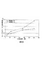
図2aに、MEAに渡って温度差が2通りの場合において、時間経過にともなうMEAを介した水の移動速度を示す。両方の場合も、概ね一定速度での水の移動が観察されたことは、水の移動が濃度勾配によって決定されることを示唆している。 FIG. 2a shows the moving speed of water through the MEA over time when there are two temperature differences across the MEA. In both cases, the observed movement of water at a roughly constant rate suggests that the movement of water is determined by the concentration gradient.
実施例1の燃料電池の構成と同様な燃料電池の構成で、カソードフローフィールドプレートに水が加えられたが、アノード側は乾燥した状態のものが、再び準備された。今回は、実施例1と同じ電気加熱機器を用いて、異なった温度で熱した後、水の移動速度を1分後に測定した。ここで、カソードフローフィールドプレートは、アノードより一定の5℃高い温度で保持された。再び、アノードプレートの重量増が得られた。(ここでは、高温での蒸発による水分減少を防ぐため、アノードプレートはコンデンサープレートに素早く挟み、双方のプレートを測定した。)
図2bに、時間経過にともなうMEAを介した水の移動速度をg/℃で示す。カソードプレートの温度がX軸にプロットされている。図2bには、また、温度を関数とした水の飽和圧も示している。双方とも、同じ形状を示す。温度の上昇にともない、膜を介した水の濃度勾配も拡散速度も大きくなる。In the fuel cell configuration similar to that of Example 1, water was added to the cathode flow field plate, but the anode side was again prepared in a dry state. This time, using the same electrical heating equipment as in Example 1, after heating at different temperatures, the water transfer rate was measured after 1 minute. Here, the cathode flow field plate was held at a
FIG. 2b shows the rate of water movement through MEA over time in g / ° C. The temperature of the cathode plate is plotted on the X axis. FIG. 2b also shows the water saturation pressure as a function of temperature. Both show the same shape. As the temperature increases, the concentration gradient and diffusion rate of water through the membrane increase.
本実施例は、従来のMEAを通じて、水の移動特性に関する量的情報を提供する。 This example provides quantitative information on water transfer characteristics through a conventional MEA.
(実施例3)
実施例1の燃料電池の構成と同様な燃料電池の構成で、MEAから2つの円形の部分が切り抜かれたものが、準備された。MEAは、濡らされ、これら切抜き部のガス拡散層と触媒でコーティングされた膜の重量が測定された。濡れたアノードフローフィールドプレートと乾燥したカソードフローフィールドプレートの重量も測定された。そして、燃料電池の構成は、両プレートの間にMEA(切抜き部も含む)を置いて、準備された。実施例1と同じ加熱機器を用い、60℃で約20分間、燃料電池の構成(アノードを熱くして)に渡って、約2〜3℃の温度差が生じるようにした。その後、燃料電池の構成は、解体され、各種構成要素の重量が再び測定された。温度勾配をかける前後の各構成要素中の水分重量を、既知の各構成要素の重量から減じることで計算された。その結果を表2に示す。(Example 3)
A fuel cell configuration similar to that of Example 1 with two circular portions cut out from the MEA was prepared. The MEA was wetted and the weight of these cutout gas diffusion layers and the catalyst coated membrane was measured. The weight of the wet anode flow field plate and the dry cathode flow field plate was also measured. And the structure of the fuel cell was prepared by placing MEA (including the cutout portion) between both plates. Using the same heating apparatus as in Example 1, a temperature difference of about 2 to 3 ° C. was generated over the fuel cell configuration (with the anode heated) at 60 ° C. for about 20 minutes. Thereafter, the fuel cell configuration was disassembled and the weights of the various components were measured again. The moisture weight in each component before and after applying the temperature gradient was calculated by subtracting from the weight of each known component. The results are shown in Table 2.
温度差を与えることは、アノードフローフィールドプレートにある水が、カソードフローフィールドプレートに移動する原因となる。アノードフローフィールドプレート、および、アノードガス拡散層とカソードガス拡散層は完全に乾燥している。乾燥ガスでパージして、これらの構成要素を乾燥させる必要はない。しかしながら、触媒でコーティングされた膜は、相変わらず、燃料電池の起動に十分な膜伝導性を提供すると期待される水量を維持している。(当業者なら、膜の水和性が高い方が好ましく、燃料電池スタックの所望の起動能力に応じ、シャットダウン時に、膜の水和性が高いように設計されうることは、理解される。)
本実施例は、わずかな温度差でアプリケーションしたとき、電池内の水は望ましい場所に著しく移動できることを証明している。
Giving the temperature difference causes water in the anode flow field plate to move to the cathode flow field plate. The anode flow field plate and the anode gas diffusion layer and the cathode gas diffusion layer are completely dry. There is no need to purge with dry gas to dry these components. However, the membrane coated with the catalyst still maintains the amount of water expected to provide sufficient membrane conductivity for fuel cell startup. (Those skilled in the art will appreciate that higher hydration of the membrane is preferred and can be designed to be more hydratable in shutdown depending on the desired startup capability of the fuel cell stack.)
This example demonstrates that when applied with small temperature differences, the water in the battery can move significantly to the desired location.
(実施例4)
直列スタックが、実施例1と同様の燃料電池30個を用いて、準備された。各電池において、アノードフローフィールドプレートは、組み立て前に約3〜4gの水で濡らされた。断熱(発泡体(foam))が、スタックの全周囲を包まれ、個別に制御可能な加熱バスプレートが、スタックの各端に設置された。スタックは、次いで、独創的な冷却方法後の水分布と、従来型の冷却手順後の水分布の結果を比較するために、用いられた。Example 4
A series stack was prepared using 30 fuel cells similar to Example 1. In each cell, the anode flow field plate was wetted with about 3-4 g of water prior to assembly. Thermal insulation (foam) was wrapped around the entire periphery of the stack, and individually controllable heating bath plates were installed at each end of the stack. The stack was then used to compare the water distribution after the original cooling method with the results of the water distribution after the conventional cooling procedure.
本発明の独創的な冷却方法は、ヒーターを用い、スタックのアノード端を80℃に、カソード端を50℃に加熱することで達成された。一度、均衡が得られると、スタックに渡る温度差を改善するために、カソード側のヒーターは切られた。次いで、この冷却によって、時間とともに、アノード側の温度も徐々に下がった。図3aは、冷却中の様々な時間における燃料電池スタックに渡る温度プロファイルである。ここで、この冷却期間中に、単調な温度減少が、スタックに渡って維持されている。スタックが約30℃に下がったときに、スタックは分解され、水分布が分析された。分析には、(1)アノードフローフィールドプレートおよびカソードフローフィールドプレート中の水量の目視推測、(2)MEA全体の水の重量測定、(3)MEAサンプル構成要素(実施例3のようにMEAから円形の切り抜き部)中の水の重量測定を含む。比較のために、上述のように、スタックは再度作成されたが、今回はカソード端およびアノード端の双方を80℃まで加熱した。一度、均衡が得られると、ヒーターは単に切られた。その後、従来型の冷却が行われ、スタックは周囲の環境によって、自然に熱を失った。図3bは、従来型の冷却中の様々な時間における燃料電池スタックに渡る温度プロファイルである。この場合、スタックの両端が、その両端間の電池より、早く冷え、凸型の温度プロファイルが観察された。 The inventive cooling method was accomplished by using a heater and heating the anode end of the stack to 80 ° C. and the cathode end to 50 ° C. Once equilibrium was achieved, the cathode heater was turned off to improve the temperature differential across the stack. Next, this cooling gradually lowered the temperature on the anode side with time. FIG. 3a is a temperature profile across the fuel cell stack at various times during cooling. Here, during this cooling period, a monotonic temperature decrease is maintained across the stack. When the stack fell to about 30 ° C., the stack was decomposed and the water distribution was analyzed. The analysis included (1) visual estimation of the amount of water in the anode flow field plate and cathode flow field plate, (2) weight measurement of the entire MEA, (3) MEA sample components (from the MEA as in Example 3). Including weight measurement of water in the circular cutout). For comparison, the stack was recreated as described above, but this time both the cathode and anode ends were heated to 80 ° C. Once equilibrium was achieved, the heater was simply turned off. Later, conventional cooling occurred and the stack naturally lost heat due to the surrounding environment. FIG. 3b is a temperature profile across the fuel cell stack at various times during conventional cooling. In this case, both ends of the stack cooled faster than the battery between the ends, and a convex temperature profile was observed.
この2つの冷却手順で、水分布には、著しい差が生じた。目視では、本独創的な方法でスタックが冷却されたとき、アノードプレート中の液体水の量は、基本的に全て、カソードプレートに移動されたようであった。しかしながら、従来方法で冷却された場合、カソードプレートとアノードプレートのそれぞれの水の量は、非常にばらつきがあった。カソードプレートは著しい量の水を含んでいた一方、他の電池では、アノードプレートに液体水のほとんどを有していた。従来型手法で冷却された電池から得られたMEAの水量(約0.5〜1.5g)は、本独創的な方法を用いて冷却された電池から得られたMEAの水量(約0.4〜1.1g)より、多かった。しかしながら、いずれの場合も、膜電解質の伝導性のための水量としては適切な量である(各電池の電解質のための推定最大水量は、約0.6〜0.8g)。最後に、MEA全体からの結果から期待されることとして、MEA中の膜電解質は、従来型冷却後の方が、本独創的な冷却後より、多くの水を含む。さらに、従来型冷却後に、幾つかのガス拡散層に液体水が見つかったのに対し、本独創的な冷却後では、見つからなかった。上述のように、液体水が存在すると、電池が0℃未満で蓄電されるときに問題を生じる。 There were significant differences in the water distribution between the two cooling procedures. Visually, when the stack was cooled in this inventive way, it seemed that essentially all of the amount of liquid water in the anode plate was transferred to the cathode plate. However, when cooled by the conventional method, the amount of water in each of the cathode plate and the anode plate varied greatly. The cathode plate contained a significant amount of water, while other cells had most of the liquid water in the anode plate. The amount of MEA water (about 0.5 to 1.5 g) obtained from the battery cooled by the conventional method is equal to the amount of MEA water obtained from the battery cooled using the inventive method (about 0.005%). 4 to 1.1 g). However, in any case, the amount of water for the conductivity of the membrane electrolyte is an appropriate amount (the estimated maximum amount of water for the electrolyte of each battery is about 0.6-0.8 g). Finally, as expected from the overall MEA results, the membrane electrolyte in the MEA contains more water after conventional cooling than after this inventive cooling. Furthermore, liquid water was found in several gas diffusion layers after conventional cooling, but not after this original cooling. As described above, the presence of liquid water causes problems when the battery is charged below 0 ° C.
従来型冷却方法に対し、本独創的な冷却方法の利点は、水を所望の分布にさせることができる点であることを、本実施例は示している。 The present example shows that the advantage of the inventive cooling method over the conventional cooling method is that water can be distributed in a desired distribution.
(実施例5)
直列スタックが、実施例1と同様の燃料電池10個を用いて、準備された。スタックのカソード端に隣接して、電気ヒーターが取り付けられた。その後、スタックは、従来型の「湿式」条件(つまり、電流密度が1A/cm2、動作温度が60℃、水素と空気反応剤が29psiで、64℃の露点で供給され、かつ、化学量論組成がそれぞれ1.7と1.5)で、1時間、定常状態で動作させた。その後、負荷は外され、反応剤の供給は、中止された。次いで、ヒーターは、4.5時間、100℃にされた。スタック中にできた温度勾配は、約15℃であった。これは電池2と電池9との間で結びついているバイポーラープレートの間で測られたものである。ヒーターは切られ、スタックは強制的に20℃に冷却された。次いで、何ら追加の処理(例えば、凍結前のパージ)を受けることなく、スタックは−15℃の冷凍機に移された。(Example 5)
A series stack was prepared using 10 fuel cells similar to Example 1. An electric heater was installed adjacent to the cathode end of the stack. The stack is then supplied in conventional “wet” conditions (ie current density of 1 A / cm2 , operating temperature of 60 ° C., hydrogen and air reactants of 29 psi, 64 ° C. dew point, and stoichiometry) The theoretical composition was 1.7 and 1.5), respectively, and was operated in steady state for 1 hour. Thereafter, the load was removed and the reactant feed was discontinued. The heater was then brought to 100 ° C. for 4.5 hours. The temperature gradient created in the stack was about 15 ° C. This is measured between bipolar plates connected between
次いで、スタックは、この凍結条件から立ち上げられ、45秒で50%の電力レベルに到達した。幾つかのパラメーター(平均電池電圧、全スタック電力の%、負荷、クーラント入口温度、および、クーラント出口温度)が時間の関数として、この立ち上げ期間中に記録された。これらを図4に示す。シャットダウン後に、従来型方式で冷却された比較のスタックは、立ち上げ中に、この電力レベルに到達するまで、相当長い時間を要する。 The stack was then launched from this freezing condition and reached a power level of 50% in 45 seconds. Several parameters (average cell voltage,% of total stack power, load, coolant inlet temperature, and coolant outlet temperature) were recorded during this ramp up as a function of time. These are shown in FIG. After shutdown, a comparative stack cooled in a conventional manner takes a considerable amount of time to reach this power level during start-up.
本実施例が示しているのは、本発明の方法は、実用的なSPE燃料電池スタックにおいて、効果的であることである。 This example shows that the method of the present invention is effective in a practical SPE fuel cell stack.
本発明の特定の要素、実施形態およびアプリケーションが、ここまでに示され、記されたが、本発明は、これらに限定されないということは、当然、理解されるべきである。なぜなら、特に、前述の教示の観点から、本開示の精神と要旨から逸脱しない範囲で、当業者なら変更可能だからである。 While specific elements, embodiments and applications of the present invention have been shown and described so far, it should be understood that the present invention is not limited thereto. This is because, in particular, in view of the above teaching, those skilled in the art can make changes without departing from the spirit and gist of the present disclosure.
Claims (22)
Translated fromJapanese該スタックからの発電を停止することと、
冷却期間にわたって、該スタックを冷却可能とすることと、
該冷却期間中、各燃料電池の該カソード側と該アノード側との間において温度差を維持することであって、各燃料電池の該温度差の方向は同じである、ことと
を包含する、方法A method of shutting down a fuel cell stack having at least two fuel cells stacked in series, each fuel cell having a cathode side and an anode side, the method comprising:
Stopping power generation from the stack;
Allowing the stack to cool over a cooling period;
Maintaining a temperature difference between the cathode side and the anode side of each fuel cell during the cooling period, wherein the direction of the temperature difference of each fuel cell is the same. Method
請求項1に記載の方法に従って該スタックをシャットダウンする手段と
を備える、燃料電池システム。A fuel cell stack having at least two fuel cells stacked in series, each fuel cell having a cathode side and an anode side;
A fuel cell system comprising: means for shutting down the stack according to the method of claim 1.
Applications Claiming Priority (3)
| Application Number | Priority Date | Filing Date | Title |
|---|---|---|---|
| US66109303A | 2003-09-12 | 2003-09-12 | |
| US10/661,093 | 2003-09-12 | ||
| PCT/US2004/029905WO2005029617A2 (en) | 2003-09-12 | 2004-09-10 | Shutdown methods and designs for fuel cell stacks |
Publications (2)
| Publication Number | Publication Date |
|---|---|
| JP2007505473A JP2007505473A (en) | 2007-03-08 |
| JP4825671B2true JP4825671B2 (en) | 2011-11-30 |
Family
ID=34375780
Family Applications (1)
| Application Number | Title | Priority Date | Filing Date |
|---|---|---|---|
| JP2006526384AExpired - LifetimeJP4825671B2 (en) | 2003-09-12 | 2004-09-10 | Method for shutting down fuel cell stack and fuel cell system |
Country Status (6)
| Country | Link |
|---|---|
| EP (1) | EP1668734B1 (en) |
| JP (1) | JP4825671B2 (en) |
| KR (1) | KR101131451B1 (en) |
| CN (1) | CN100433434C (en) |
| CA (1) | CA2538306C (en) |
| WO (1) | WO2005029617A2 (en) |
Families Citing this family (6)
| Publication number | Priority date | Publication date | Assignee | Title |
|---|---|---|---|---|
| KR100585476B1 (en) | 2002-11-12 | 2006-06-07 | 에이에스엠엘 네델란즈 비.브이. | Lithographic Apparatus and Device Manufacturing Method |
| US7964315B2 (en) | 2003-09-12 | 2011-06-21 | Bdf Ip Holdings Ltd. | Shutdown methods and designs for fuel cell stacks |
| US7390586B2 (en) | 2004-03-10 | 2008-06-24 | Ballard Power Systems, Inc. | Fuel cell stacks of alternating polarity membrane electrode assemblies |
| CA2597461A1 (en) | 2005-03-11 | 2006-09-21 | Ballard Power Systems Inc. | Shutdown methods and designs for fuel cell stacks |
| KR100932214B1 (en)* | 2005-10-14 | 2009-12-16 | 주식회사 엘지화학 | Heat exchange system of battery pack using thermoelectric elements |
| JP2008047316A (en) | 2006-08-11 | 2008-02-28 | Toyota Motor Corp | Fuel cell system |
Citations (1)
| Publication number | Priority date | Publication date | Assignee | Title |
|---|---|---|---|---|
| JPH09312165A (en)* | 1996-05-23 | 1997-12-02 | Aqueous Res:Kk | Fuel cell power generator and operating method thereof |
Family Cites Families (5)
| Publication number | Priority date | Publication date | Assignee | Title |
|---|---|---|---|---|
| JPH08306380A (en)* | 1995-05-09 | 1996-11-22 | Fuji Electric Co Ltd | Stacked fuel cell |
| US6093500A (en)* | 1998-07-28 | 2000-07-25 | International Fuel Cells Corporation | Method and apparatus for operating a fuel cell system |
| EP1216489A1 (en)* | 1999-04-23 | 2002-06-26 | Teledyne Energy Systems, Inc. | Freeze tolerant fuel cell system and method |
| JP3734134B2 (en) | 1999-06-30 | 2006-01-11 | 富士電機ホールディングス株式会社 | Polymer electrolyte fuel cell |
| US7132179B2 (en)* | 2001-03-28 | 2006-11-07 | Ballard Power Systems Inc. | Methods and apparatus for improving the cold starting capability of a fuel cell |
- 2004
- 2004-09-10JPJP2006526384Apatent/JP4825671B2/ennot_activeExpired - Lifetime
- 2004-09-10CACA2538306Apatent/CA2538306C/ennot_activeExpired - Lifetime
- 2004-09-10KRKR1020067007053Apatent/KR101131451B1/ennot_activeExpired - Lifetime
- 2004-09-10CNCNB2004800300960Apatent/CN100433434C/ennot_activeExpired - Lifetime
- 2004-09-10WOPCT/US2004/029905patent/WO2005029617A2/enactiveApplication Filing
- 2004-09-10EPEP04783934.5Apatent/EP1668734B1/ennot_activeExpired - Lifetime
Patent Citations (1)
| Publication number | Priority date | Publication date | Assignee | Title |
|---|---|---|---|---|
| JPH09312165A (en)* | 1996-05-23 | 1997-12-02 | Aqueous Res:Kk | Fuel cell power generator and operating method thereof |
Also Published As
| Publication number | Publication date |
|---|---|
| EP1668734B1 (en) | 2017-02-08 |
| CA2538306A1 (en) | 2005-03-31 |
| KR20060128863A (en) | 2006-12-14 |
| EP1668734A2 (en) | 2006-06-14 |
| CN1868087A (en) | 2006-11-22 |
| WO2005029617A2 (en) | 2005-03-31 |
| WO2005029617A3 (en) | 2006-01-26 |
| CA2538306C (en) | 2012-08-14 |
| CN100433434C (en) | 2008-11-12 |
| JP2007505473A (en) | 2007-03-08 |
| KR101131451B1 (en) | 2012-04-23 |
Similar Documents
| Publication | Publication Date | Title |
|---|---|---|
| US20050202294A1 (en) | Fuel cell stacks of alternating polarity membrane electrode assemblies | |
| JP5325929B2 (en) | Method for improving the cold start capability of an electrochemical fuel cell | |
| JP4902883B2 (en) | Fuel cell stack shutdown method and design | |
| WO2006081009A2 (en) | Method and device to improve operation of a fuel cell | |
| JP4825671B2 (en) | Method for shutting down fuel cell stack and fuel cell system | |
| CN113366152A (en) | Electrochemical hydrogen pump and control method thereof | |
| US7955748B2 (en) | Cell or stack for evaluating performance of fuel cell and method of evaluating performance of fuel cell using the same | |
| EP2639869B1 (en) | Operation method of polymer electrolyte fuel cell system and polymer electrolyte fuel cell system | |
| US7964315B2 (en) | Shutdown methods and designs for fuel cell stacks | |
| US8178252B2 (en) | Method to maximize fuel cell voltage during start-up | |
| CA2613353A1 (en) | Thermal control of fuel cell for improved cold start | |
| Patterson et al. | PEM fuel cell freeze durability and cold start project | |
| Rea | Degradation of a polymer electrolyte membrane fuel cell under freeze start-up operation | |
| Zaffou et al. | Effects of temperature difference on water management in PEMFCs | |
| JP2009259664A (en) | Fuel cell and its manufacturing method |
Legal Events
| Date | Code | Title | Description |
|---|---|---|---|
| A621 | Written request for application examination | Free format text:JAPANESE INTERMEDIATE CODE: A621 Effective date:20070907 | |
| A711 | Notification of change in applicant | Free format text:JAPANESE INTERMEDIATE CODE: A711 Effective date:20090528 | |
| A131 | Notification of reasons for refusal | Free format text:JAPANESE INTERMEDIATE CODE: A131 Effective date:20110331 | |
| A521 | Request for written amendment filed | Free format text:JAPANESE INTERMEDIATE CODE: A523 Effective date:20110628 | |
| TRDD | Decision of grant or rejection written | ||
| A01 | Written decision to grant a patent or to grant a registration (utility model) | Free format text:JAPANESE INTERMEDIATE CODE: A01 Effective date:20110901 | |
| A01 | Written decision to grant a patent or to grant a registration (utility model) | Free format text:JAPANESE INTERMEDIATE CODE: A01 | |
| A61 | First payment of annual fees (during grant procedure) | Free format text:JAPANESE INTERMEDIATE CODE: A61 Effective date:20110912 | |
| R150 | Certificate of patent or registration of utility model | Ref document number:4825671 Country of ref document:JP Free format text:JAPANESE INTERMEDIATE CODE: R150 Free format text:JAPANESE INTERMEDIATE CODE: R150 | |
| FPAY | Renewal fee payment (event date is renewal date of database) | Free format text:PAYMENT UNTIL: 20140916 Year of fee payment:3 | |
| R250 | Receipt of annual fees | Free format text:JAPANESE INTERMEDIATE CODE: R250 | |
| R250 | Receipt of annual fees | Free format text:JAPANESE INTERMEDIATE CODE: R250 | |
| R250 | Receipt of annual fees | Free format text:JAPANESE INTERMEDIATE CODE: R250 | |
| R250 | Receipt of annual fees | Free format text:JAPANESE INTERMEDIATE CODE: R250 | |
| R250 | Receipt of annual fees | Free format text:JAPANESE INTERMEDIATE CODE: R250 | |
| R250 | Receipt of annual fees | Free format text:JAPANESE INTERMEDIATE CODE: R250 | |
| R250 | Receipt of annual fees | Free format text:JAPANESE INTERMEDIATE CODE: R250 | |
| R250 | Receipt of annual fees | Free format text:JAPANESE INTERMEDIATE CODE: R250 | |
| R250 | Receipt of annual fees | Free format text:JAPANESE INTERMEDIATE CODE: R250 | |
| R250 | Receipt of annual fees | Free format text:JAPANESE INTERMEDIATE CODE: R250 | |
| EXPY | Cancellation because of completion of term |