JP4824747B2 - Intravascular stent and intravascular stent delivery system - Google Patents
Intravascular stent and intravascular stent delivery systemDownload PDFInfo
- Publication number
- JP4824747B2 JP4824747B2JP2008503009AJP2008503009AJP4824747B2JP 4824747 B2JP4824747 B2JP 4824747B2JP 2008503009 AJP2008503009 AJP 2008503009AJP 2008503009 AJP2008503009 AJP 2008503009AJP 4824747 B2JP4824747 B2JP 4824747B2
- Authority
- JP
- Japan
- Prior art keywords
- stent
- frame
- catheter
- biodegradable
- balloon
- Prior art date
- Legal status (The legal status is an assumption and is not a legal conclusion. Google has not performed a legal analysis and makes no representation as to the accuracy of the status listed.)
- Expired - Fee Related
Links
- 239000000463materialSubstances0.000claimsdescription44
- 239000003814drugSubstances0.000claimsdescription18
- 229940124597therapeutic agentDrugs0.000claimsdescription9
- 238000000034methodMethods0.000description14
- 238000000576coating methodMethods0.000description12
- 210000004204blood vesselAnatomy0.000description11
- 239000011248coating agentSubstances0.000description11
- 238000002399angioplastyMethods0.000description9
- 239000000835fiberSubstances0.000description9
- 210000001367arteryAnatomy0.000description8
- 229940079593drugDrugs0.000description8
- 229910052751metalInorganic materials0.000description8
- 239000002184metalSubstances0.000description8
- 238000013461designMethods0.000description7
- 208000037803restenosisDiseases0.000description7
- 229920000642polymerPolymers0.000description6
- 239000003795chemical substances by applicationSubstances0.000description5
- -1polypropylenePolymers0.000description4
- 229920005989resinPolymers0.000description4
- 239000011347resinSubstances0.000description4
- 230000001225therapeutic effectEffects0.000description4
- 239000004677NylonSubstances0.000description3
- 208000031481Pathologic ConstrictionDiseases0.000description3
- 206010038563ReocclusionDiseases0.000description3
- 239000004744fabricSubstances0.000description3
- 229920001778nylonPolymers0.000description3
- 208000037804stenosisDiseases0.000description3
- 230000036262stenosisEffects0.000description3
- 239000000126substanceSubstances0.000description3
- 230000001629suppressionEffects0.000description3
- DSUFPYCILZXJFF-UHFFFAOYSA-N4-[[4-[[4-(pentoxycarbonylamino)cyclohexyl]methyl]cyclohexyl]carbamoyloxy]butyl n-[4-[[4-(butoxycarbonylamino)cyclohexyl]methyl]cyclohexyl]carbamateChemical compoundC1CC(NC(=O)OCCCCC)CCC1CC1CCC(NC(=O)OCCCCOC(=O)NC2CCC(CC3CCC(CC3)NC(=O)OCCCC)CC2)CC1DSUFPYCILZXJFF-UHFFFAOYSA-N0.000description2
- MWUXSHHQAYIFBG-UHFFFAOYSA-NNitric oxideChemical compoundO=[N]MWUXSHHQAYIFBG-UHFFFAOYSA-N0.000description2
- 229920002614Polyether block amidePolymers0.000description2
- 230000001028anti-proliverative effectEffects0.000description2
- 239000000919ceramicSubstances0.000description2
- PCHJSUWPFVWCPO-UHFFFAOYSA-NgoldChemical compound[Au]PCHJSUWPFVWCPO-UHFFFAOYSA-N0.000description2
- 239000010931goldSubstances0.000description2
- 229910052737goldInorganic materials0.000description2
- 239000003102growth factorSubstances0.000description2
- 239000000203mixtureSubstances0.000description2
- BASFCYQUMIYNBI-UHFFFAOYSA-NplatinumChemical compound[Pt]BASFCYQUMIYNBI-UHFFFAOYSA-N0.000description2
- 239000005020polyethylene terephthalateSubstances0.000description2
- 229920000139polyethylene terephthalatePolymers0.000description2
- 229920001343polytetrafluoroethylenePolymers0.000description2
- 239000004810polytetrafluoroethyleneSubstances0.000description2
- 239000002904solventSubstances0.000description2
- 238000001356surgical procedureMethods0.000description2
- 208000024891symptomDiseases0.000description2
- 208000019553vascular diseaseDiseases0.000description2
- 210000005166vasculatureAnatomy0.000description2
- 238000012800visualizationMethods0.000description2
- 229940127291Calcium channel antagonistDrugs0.000description1
- 229920001780ECTFEPolymers0.000description1
- 108090000790EnzymesProteins0.000description1
- 102000004190EnzymesHuman genes0.000description1
- VGGSQFUCUMXWEO-UHFFFAOYSA-NEtheneChemical compoundC=CVGGSQFUCUMXWEO-UHFFFAOYSA-N0.000description1
- JOYRKODLDBILNP-UHFFFAOYSA-NEthyl urethaneChemical compoundCCOC(N)=OJOYRKODLDBILNP-UHFFFAOYSA-N0.000description1
- 239000005977EthyleneSubstances0.000description1
- 108010070716Intercellular Signaling Peptides and ProteinsProteins0.000description1
- 102000005755Intercellular Signaling Peptides and ProteinsHuman genes0.000description1
- GRYLNZFGIOXLOG-UHFFFAOYSA-NNitric acidChemical compoundO[N+]([O-])=OGRYLNZFGIOXLOG-UHFFFAOYSA-N0.000description1
- 108091034117OligonucleotideProteins0.000description1
- 239000004698PolyethyleneSubstances0.000description1
- 239000004743PolypropyleneSubstances0.000description1
- 208000007536ThrombosisDiseases0.000description1
- RTAQQCXQSZGOHL-UHFFFAOYSA-NTitaniumChemical compound[Ti]RTAQQCXQSZGOHL-UHFFFAOYSA-N0.000description1
- 229920006099Vestamid®Polymers0.000description1
- 241000700605VirusesSpecies0.000description1
- JLCPHMBAVCMARE-UHFFFAOYSA-N[3-[[3-[[3-[[3-[[3-[[3-[[3-[[3-[[3-[[3-[[3-[[5-(2-amino-6-oxo-1H-purin-9-yl)-3-[[3-[[3-[[3-[[3-[[3-[[5-(2-amino-6-oxo-1H-purin-9-yl)-3-[[5-(2-amino-6-oxo-1H-purin-9-yl)-3-hydroxyoxolan-2-yl]methoxy-hydroxyphosphoryl]oxyoxolan-2-yl]methoxy-hydroxyphosphoryl]oxy-5-(5-methyl-2,4-dioxopyrimidin-1-yl)oxolan-2-yl]methoxy-hydroxyphosphoryl]oxy-5-(6-aminopurin-9-yl)oxolan-2-yl]methoxy-hydroxyphosphoryl]oxy-5-(6-aminopurin-9-yl)oxolan-2-yl]methoxy-hydroxyphosphoryl]oxy-5-(6-aminopurin-9-yl)oxolan-2-yl]methoxy-hydroxyphosphoryl]oxy-5-(6-aminopurin-9-yl)oxolan-2-yl]methoxy-hydroxyphosphoryl]oxyoxolan-2-yl]methoxy-hydroxyphosphoryl]oxy-5-(5-methyl-2,4-dioxopyrimidin-1-yl)oxolan-2-yl]methoxy-hydroxyphosphoryl]oxy-5-(4-amino-2-oxopyrimidin-1-yl)oxolan-2-yl]methoxy-hydroxyphosphoryl]oxy-5-(5-methyl-2,4-dioxopyrimidin-1-yl)oxolan-2-yl]methoxy-hydroxyphosphoryl]oxy-5-(5-methyl-2,4-dioxopyrimidin-1-yl)oxolan-2-yl]methoxy-hydroxyphosphoryl]oxy-5-(6-aminopurin-9-yl)oxolan-2-yl]methoxy-hydroxyphosphoryl]oxy-5-(6-aminopurin-9-yl)oxolan-2-yl]methoxy-hydroxyphosphoryl]oxy-5-(4-amino-2-oxopyrimidin-1-yl)oxolan-2-yl]methoxy-hydroxyphosphoryl]oxy-5-(4-amino-2-oxopyrimidin-1-yl)oxolan-2-yl]methoxy-hydroxyphosphoryl]oxy-5-(4-amino-2-oxopyrimidin-1-yl)oxolan-2-yl]methoxy-hydroxyphosphoryl]oxy-5-(6-aminopurin-9-yl)oxolan-2-yl]methoxy-hydroxyphosphoryl]oxy-5-(4-amino-2-oxopyrimidin-1-yl)oxolan-2-yl]methyl [5-(6-aminopurin-9-yl)-2-(hydroxymethyl)oxolan-3-yl] hydrogen phosphatePolymersCc1cn(C2CC(OP(O)(=O)OCC3OC(CC3OP(O)(=O)OCC3OC(CC3O)n3cnc4c3nc(N)[nH]c4=O)n3cnc4c3nc(N)[nH]c4=O)C(COP(O)(=O)OC3CC(OC3COP(O)(=O)OC3CC(OC3COP(O)(=O)OC3CC(OC3COP(O)(=O)OC3CC(OC3COP(O)(=O)OC3CC(OC3COP(O)(=O)OC3CC(OC3COP(O)(=O)OC3CC(OC3COP(O)(=O)OC3CC(OC3COP(O)(=O)OC3CC(OC3COP(O)(=O)OC3CC(OC3COP(O)(=O)OC3CC(OC3COP(O)(=O)OC3CC(OC3COP(O)(=O)OC3CC(OC3COP(O)(=O)OC3CC(OC3COP(O)(=O)OC3CC(OC3COP(O)(=O)OC3CC(OC3COP(O)(=O)OC3CC(OC3CO)n3cnc4c(N)ncnc34)n3ccc(N)nc3=O)n3cnc4c(N)ncnc34)n3ccc(N)nc3=O)n3ccc(N)nc3=O)n3ccc(N)nc3=O)n3cnc4c(N)ncnc34)n3cnc4c(N)ncnc34)n3cc(C)c(=O)[nH]c3=O)n3cc(C)c(=O)[nH]c3=O)n3ccc(N)nc3=O)n3cc(C)c(=O)[nH]c3=O)n3cnc4c3nc(N)[nH]c4=O)n3cnc4c(N)ncnc34)n3cnc4c(N)ncnc34)n3cnc4c(N)ncnc34)n3cnc4c(N)ncnc34)O2)c(=O)[nH]c1=OJLCPHMBAVCMARE-UHFFFAOYSA-N0.000description1
- 239000000853adhesiveSubstances0.000description1
- 230000001070adhesive effectEffects0.000description1
- 230000033115angiogenesisEffects0.000description1
- 239000004037angiogenesis inhibitorSubstances0.000description1
- 230000003466anti-cipated effectEffects0.000description1
- 239000002260anti-inflammatory agentSubstances0.000description1
- 229940121363anti-inflammatory agentDrugs0.000description1
- 230000001621anti-mitogenic effectEffects0.000description1
- 230000002137anti-vascular effectEffects0.000description1
- 239000003963antioxidant agentSubstances0.000description1
- 229940127218antiplatelet drugDrugs0.000description1
- 210000000013bile ductAnatomy0.000description1
- 239000000560biocompatible materialSubstances0.000description1
- 230000015572biosynthetic processEffects0.000description1
- 230000000903blocking effectEffects0.000description1
- 230000017531blood circulationEffects0.000description1
- 239000000480calcium channel blockerSubstances0.000description1
- 230000000747cardiac effectEffects0.000description1
- 230000004663cell proliferationEffects0.000description1
- UUAGAQFQZIEFAH-UHFFFAOYSA-NchlorotrifluoroethyleneChemical groupFC(F)=C(F)ClUUAGAQFQZIEFAH-UHFFFAOYSA-N0.000description1
- 229920001577copolymerPolymers0.000description1
- 238000000151depositionMethods0.000description1
- 230000008021depositionEffects0.000description1
- 238000007598dipping methodMethods0.000description1
- 230000000694effectsEffects0.000description1
- 210000002889endothelial cellAnatomy0.000description1
- 210000003989endothelium vascularAnatomy0.000description1
- 210000003238esophagusAnatomy0.000description1
- 239000002657fibrous materialSubstances0.000description1
- 238000002594fluoroscopyMethods0.000description1
- 238000009472formulationMethods0.000description1
- 210000001035gastrointestinal tractAnatomy0.000description1
- 238000001727in vivoMethods0.000description1
- 238000011065in-situ storageMethods0.000description1
- 239000003112inhibitorSubstances0.000description1
- 238000002347injectionMethods0.000description1
- 239000007924injectionSubstances0.000description1
- 238000013152interventional procedureMethods0.000description1
- 238000002608intravascular ultrasoundMethods0.000description1
- 239000007788liquidSubstances0.000description1
- 230000002101lytic effectEffects0.000description1
- 229910001092metal group alloyInorganic materials0.000description1
- 150000002739metalsChemical class0.000description1
- 239000003226mitogenSubstances0.000description1
- 238000012986modificationMethods0.000description1
- 230000004048modificationEffects0.000description1
- 208000010125myocardial infarctionDiseases0.000description1
- 229910052758niobiumInorganic materials0.000description1
- 239000010955niobiumSubstances0.000description1
- GUCVJGMIXFAOAE-UHFFFAOYSA-Nniobium atomChemical compound[Nb]GUCVJGMIXFAOAE-UHFFFAOYSA-N0.000description1
- 229910017604nitric acidInorganic materials0.000description1
- 230000002093peripheral effectEffects0.000description1
- 239000004033plasticSubstances0.000description1
- 229920003023plasticPolymers0.000description1
- 239000000106platelet aggregation inhibitorSubstances0.000description1
- 229910052697platinumInorganic materials0.000description1
- 229920000573polyethylenePolymers0.000description1
- 229920002959polymer blendPolymers0.000description1
- 229920001155polypropylenePolymers0.000description1
- 230000002980postoperative effectEffects0.000description1
- 108090000765processed proteins & peptidesProteins0.000description1
- 238000004393prognosisMethods0.000description1
- 108090000623proteins and genesProteins0.000description1
- 230000005855radiationEffects0.000description1
- 230000003014reinforcing effectEffects0.000description1
- 230000003252repetitive effectEffects0.000description1
- 239000000243solutionSubstances0.000description1
- 238000004528spin coatingMethods0.000description1
- 238000005507sprayingMethods0.000description1
- 239000010935stainless steelSubstances0.000description1
- 229910001220stainless steelInorganic materials0.000description1
- 230000002966stenotic effectEffects0.000description1
- 239000000758substrateSubstances0.000description1
- 229910052715tantalumInorganic materials0.000description1
- GUVRBAGPIYLISA-UHFFFAOYSA-Ntantalum atomChemical compound[Ta]GUVRBAGPIYLISA-UHFFFAOYSA-N0.000description1
- 229940126585therapeutic drugDrugs0.000description1
- 229920002725thermoplastic elastomerPolymers0.000description1
- 230000008719thickeningEffects0.000description1
- 210000001519tissueAnatomy0.000description1
- 229910052719titaniumInorganic materials0.000description1
- 239000010936titaniumSubstances0.000description1
- 238000012546transferMethods0.000description1
- WFKWXMTUELFFGS-UHFFFAOYSA-NtungstenChemical compound[W]WFKWXMTUELFFGS-UHFFFAOYSA-N0.000description1
- 229910052721tungstenInorganic materials0.000description1
- 239000010937tungstenSubstances0.000description1
- 229940124549vasodilatorDrugs0.000description1
- 239000003071vasodilator agentSubstances0.000description1
- 238000003466weldingMethods0.000description1
Images

Classifications
- A—HUMAN NECESSITIES
- A61—MEDICAL OR VETERINARY SCIENCE; HYGIENE
- A61L—METHODS OR APPARATUS FOR STERILISING MATERIALS OR OBJECTS IN GENERAL; DISINFECTION, STERILISATION OR DEODORISATION OF AIR; CHEMICAL ASPECTS OF BANDAGES, DRESSINGS, ABSORBENT PADS OR SURGICAL ARTICLES; MATERIALS FOR BANDAGES, DRESSINGS, ABSORBENT PADS OR SURGICAL ARTICLES
- A61L31/00—Materials for other surgical articles, e.g. stents, stent-grafts, shunts, surgical drapes, guide wires, materials for adhesion prevention, occluding devices, surgical gloves, tissue fixation devices
- A61L31/14—Materials characterised by their function or physical properties, e.g. injectable or lubricating compositions, shape-memory materials, surface modified materials
- A61L31/148—Materials at least partially resorbable by the body
- A—HUMAN NECESSITIES
- A61—MEDICAL OR VETERINARY SCIENCE; HYGIENE
- A61L—METHODS OR APPARATUS FOR STERILISING MATERIALS OR OBJECTS IN GENERAL; DISINFECTION, STERILISATION OR DEODORISATION OF AIR; CHEMICAL ASPECTS OF BANDAGES, DRESSINGS, ABSORBENT PADS OR SURGICAL ARTICLES; MATERIALS FOR BANDAGES, DRESSINGS, ABSORBENT PADS OR SURGICAL ARTICLES
- A61L31/00—Materials for other surgical articles, e.g. stents, stent-grafts, shunts, surgical drapes, guide wires, materials for adhesion prevention, occluding devices, surgical gloves, tissue fixation devices
- A61L31/14—Materials characterised by their function or physical properties, e.g. injectable or lubricating compositions, shape-memory materials, surface modified materials
- A61L31/16—Biologically active materials, e.g. therapeutic substances
- A—HUMAN NECESSITIES
- A61—MEDICAL OR VETERINARY SCIENCE; HYGIENE
- A61F—FILTERS IMPLANTABLE INTO BLOOD VESSELS; PROSTHESES; DEVICES PROVIDING PATENCY TO, OR PREVENTING COLLAPSING OF, TUBULAR STRUCTURES OF THE BODY, e.g. STENTS; ORTHOPAEDIC, NURSING OR CONTRACEPTIVE DEVICES; FOMENTATION; TREATMENT OR PROTECTION OF EYES OR EARS; BANDAGES, DRESSINGS OR ABSORBENT PADS; FIRST-AID KITS
- A61F2/00—Filters implantable into blood vessels; Prostheses, i.e. artificial substitutes or replacements for parts of the body; Appliances for connecting them with the body; Devices providing patency to, or preventing collapsing of, tubular structures of the body, e.g. stents
- A61F2/82—Devices providing patency to, or preventing collapsing of, tubular structures of the body, e.g. stents
- A61F2/86—Stents in a form characterised by the wire-like elements; Stents in the form characterised by a net-like or mesh-like structure
- A—HUMAN NECESSITIES
- A61—MEDICAL OR VETERINARY SCIENCE; HYGIENE
- A61L—METHODS OR APPARATUS FOR STERILISING MATERIALS OR OBJECTS IN GENERAL; DISINFECTION, STERILISATION OR DEODORISATION OF AIR; CHEMICAL ASPECTS OF BANDAGES, DRESSINGS, ABSORBENT PADS OR SURGICAL ARTICLES; MATERIALS FOR BANDAGES, DRESSINGS, ABSORBENT PADS OR SURGICAL ARTICLES
- A61L2300/00—Biologically active materials used in bandages, wound dressings, absorbent pads or medical devices
Landscapes
- Health & Medical Sciences (AREA)
- Life Sciences & Earth Sciences (AREA)
- General Health & Medical Sciences (AREA)
- Epidemiology (AREA)
- Veterinary Medicine (AREA)
- Public Health (AREA)
- Animal Behavior & Ethology (AREA)
- Heart & Thoracic Surgery (AREA)
- Surgery (AREA)
- Vascular Medicine (AREA)
- Molecular Biology (AREA)
- Engineering & Computer Science (AREA)
- Chemical & Material Sciences (AREA)
- Medicinal Chemistry (AREA)
- Biomedical Technology (AREA)
- Media Introduction/Drainage Providing Device (AREA)
- Prostheses (AREA)
Description
Translated fromJapanese本発明は、広義には、移植可能な医療装置の分野に関するものである。特に、本発明は、血管内ステント、および、血管内ステント搬送システムに関連している。The present invention broadly relates to the field of implantable medical devices. In particular, the present invention relates tointravascular stents and intravascular stent delivery systems .
バルーン血管形成は、プラーク堆積によって狭窄した閉塞状態の血管を広げるための医療処置である。この処置は、心臓動脈または抹消動脈で利用される。血管形成処置では、遠位端に特殊な膨張可能バルーンを設けたカテーテルは患者動脈の中を通して操舵され、治療を受けるべき動脈の中に進入させられ、狭窄領域(狭窄症)の内側にバルーンを設置する。圧力下でバルーンを膨張させて強制的に動脈を広げることにより、狭窄症の領域が拡張される。動脈が広げられた後で、バルーンは収縮状態にされて、カテーテルが患者から取外される。 Balloon angioplasty is a medical procedure for widening an obstructed blood vessel that is constricted by plaque deposition. This procedure is utilized in cardiac or peripheral arteries. In an angioplasty procedure, a catheter with a special inflatable balloon at the distal end is steered through the patient artery and advanced into the artery to be treated, with the balloon inside the stenotic area (stenosis). Install. By inflating the balloon under pressure to force the artery to expand, the area of stenosis is expanded. After the artery is dilated, the balloon is deflated and the catheter is removed from the patient.
バルーン血管形成に付随する重大の難点は、相当数の事例で、バルーン血管形成術が実施されたのと同じ領域で動脈が再び閉塞状態になることである。このような反復閉塞は短急的で(突然の再閉鎖する)、通常はその原因となるのが、バルーン血管形成術中に動脈壁に生じた損傷の結果として自由に遊離したり自由に分解したりするプラークまたはプラーク堆積組織の初期的な弁状片(フラップ)、または、一部(セグメント)である。このような突然の再閉鎖は動脈を遮断して緊急手術を要するが、この手術は、直ちに実施されなければ、心筋梗塞を生じる結果となることがあり、死に至らしめることもある。このような危険により、バルーン血管形成処置を実施する際に、上述のような緊急手術を実施する準備のできている外科手術チームが居る必要もある。再狭窄は後で起こり、その時期は例えば、血管形成の2ヵ月後または3ヶ月後であり、その理由は、完全には解明されておらず、また、反復バルーン血管形成または反復バイパス外科手術を必要とすることがあるのがより一般的である。このように再狭窄の発生時期が遅くなるほど、症状は元の狭窄症のものに似ていることがよくあり、すなわち、再狭窄の症状は動脈壁の内外で細胞増殖と新たなプラーク堆積の様相を示す。 A significant difficulty associated with balloon angioplasty is that in a significant number of cases, the artery is again occluded in the same area where balloon angioplasty was performed. Such repetitive occlusions are short-lived (suddenly reclosed) and are usually caused by free release or free disassembly as a result of damage to the arterial wall during balloon angioplasty. Or an initial valve-like piece (flap) or part (segment) of a plaque or plaque-deposited tissue. Such sudden reclosure requires an emergency operation by blocking the artery, which if not performed immediately can result in myocardial infarction and can be fatal. Because of this danger, it is also necessary to have a surgical team ready to perform an emergency operation as described above when performing a balloon angioplasty procedure. Restenosis occurs later, for example at 2 or 3 months after angiogenesis, for reasons that are not fully understood, and that repeated balloon angioplasty or repeated bypass surgery More commonly you may need it. Thus, the later the onset of restenosis, the more often the symptoms resemble those of the original stenosis, i.e. the symptoms of restenosis are aspects of cell proliferation and new plaque buildup inside and outside the arterial wall. Indicates.
再閉塞および再狭窄の発生を低減するために、幾つかの医療戦略が開発されてきた。ステントなどのような移植可能な装置を使って、血管形成関係の再閉塞および再狭窄の再発率を約半分だけ低減するのである。このような管内装置の使用は、この種の患者の予後を大いに向上させている。ステントは血管形成術が実施された後で血管内に設置される。カテーテルは、通例は、治療を施されるべき動脈部位にステントを搬送するために使用される。ステントには、そこに1種類以上の治療物質が更に含浸または被膜されて、再閉塞または再狭窄の一方もしくはその両方を一度に抑制することもある。 Several medical strategies have been developed to reduce the occurrence of reocclusion and restenosis. Using an implantable device such as a stent, the recurrence rate of angioplasty-related reocclusion and restenosis is reduced by about half. The use of such an endovascular device greatly improves the prognosis of this type of patient. The stent is placed in the blood vessel after the angioplasty is performed. A catheter is typically used to deliver a stent to an arterial site to be treated. A stent may be further impregnated or coated with one or more therapeutic substances to inhibit one or both of reocclusion and / or restenosis at once.
無数のステント設計が当該技術で周知である。ステント設計の1種は、円筒状本体部が金属製の複数支柱材から形成されている。複数支柱材が格子状の表面を形成し、これが小径の円筒に巻き上げられる(すなわち、圧縮形状になる)。ステントは(例えば、圧縮状態で)カテーテルのバルーンの上に設置され、後の配備に備える。バルーンに設置されている間は、ステントに小さい側面寸法を与えるのが望ましいことが多い。血管内に設置されてしまうと、バルーンおよびステントは一緒に拡張状態となることができる。配備後、バルーンは収縮され、金属ステントが可塑変形されたままにされたうえで、拡張形状を示しながら血管内に残存させられる。金属ステントは、一般に、強靭かつ血管内に存在する剪断力に対する耐性がある。 A myriad of stent designs are well known in the art. In one type of stent design, the cylindrical body is formed from a metal multi-column material. Multiple struts form a grid-like surface that is rolled up into a small diameter cylinder (ie, compressed). The stent is placed over the catheter balloon (eg, in a compressed state) for later deployment. It is often desirable to give the stent a small lateral dimension while installed in the balloon. Once placed in a blood vessel, the balloon and stent can be expanded together. After deployment, the balloon is deflated, leaving the metal stent plastically deformed and remaining in the vessel, showing an expanded shape. Metal stents are generally strong and resistant to shear forces present in blood vessels.
しかしながら、金属ステントは生体分解性であるのが一般的である。よって、金属ステントは血管内に留まることができるとともに、或る状況下では回収されなければならないこともある。 However, metal stents are generally biodegradable. Thus, the metal stent can remain in the vessel and may have to be retrieved under certain circumstances.
これとは別な種類のステント設計は、円筒状本体部が繊維材(非金属製)の管状の編組メッシュ素材から形成されている。編組メッシュ素材は生体分解性である(すなわち、患者体内で抑制された態様で分解する)。繊維ステントは、適切に設置されてしまうと、自己拡張してより大きい径になる。メッシュステントは生体分解性にされてもよい。しかしながら、これらステントは、場合によっては、血管内に存在している剪断力に耐えるのに十分な機械強度を欠いていることがある。 Another type of stent design is that the cylindrical body is formed from a tubular braided mesh material of fibrous material (non-metallic). The braided mesh material is biodegradable (ie, degrades in a restrained manner in the patient). A fiber stent, when properly installed, self-expands to a larger diameter. The mesh stent may be made biodegradable. However, in some cases, these stents may lack sufficient mechanical strength to withstand the shear forces present in the blood vessel.
従って、上述の制約とそれ以外の制約を克服する生体分解性ステントと生体非分解性ステントとの混成ステント、搬送システム、および、血管疾患を治療する方法を提供するのが望ましい。 Accordingly, it would be desirable to provide a hybrid stent of biodegradable and non-biodegradable stents, a delivery system, and a method of treating vascular disease that overcomes the above and other limitations.
本発明による第1の観点は血管内ステントを提供する。ステントは、生体分解性素材から構成された枠を備えている。少なくとも1本の支柱材が生体分解性素材から構成されている。枠は少なくとも1本の支柱材に作動可能に取り付けられている。 A first aspect according to the present invention provides an intravascular stent. The stent includes a frame made of a biodegradable material. At least one support material is composed of a biodegradable material. The frame is operably attached to at least one strut material.
本発明による第2の観点は血管内ステント搬送システムを提供する。搬送システムは、カテーテルと、このカテーテルの一部に配置されたステントとを備えている。ステントは、生体分解性素材から構成された枠(フレームワーク)を備えている。ステントは、生体非分解性素材から構成された少なくとも1本の支柱材を更に備えている。枠は少なくとも1本の支柱材に作動可能に取り付けられている。 A second aspect according to the present invention provides an intravascular stent delivery system. The delivery system includes a catheter and a stent disposed on a portion of the catheter. The stent includes a frame (framework) made of a biodegradable material. The stent further includes at least one strut material made of a non-biodegradable material. The frame is operably attached to at least one strut material.
本発明に関連する技術として、血管の病気を治療する方法をあげることができる。この方法は、カテーテルにより血管内に管内ステントを設置する段階を含んでいる。このステントは、生体非分解性素材から構成されている少なくとも1本の支柱材を備えているとともに、枠に作動可能に取り付けられている。枠は、血管内ステントの配備中に拡張する。枠は血管内で生体分解することができるようになっている。As a technique related to the present invention, a methodfor treating vascular diseasescan be mentioned. The method includes placing an endovascular stent in a blood vessel with a catheter. The stent includes at least one strut member made of a non-biodegradable material and is operably attached to the frame. The frame expands during deployment of the endovascular stent. The frame can be biodegraded in the blood vessel.
本発明の上述の特徴と利点、および、それ以外の特徴と利点は、添付の図面と関連づけて理解されれば、本件の好ましい実施形態の後段の説明から更に明瞭になるだろう。図面は等尺で描かれている訳ではない。詳細な説明と図面は、本発明の範囲を制限するというようりはむしろ本発明の例示にすぎず、本発明は添付の特許請求の範囲の各請求項とその均等物によって限定されている。 The foregoing and other features and advantages of the present invention will become more apparent from the following description of the presently preferred embodiments when understood in conjunction with the accompanying drawings. The drawings are not drawn to scale. The detailed description and drawings are merely illustrative of the invention, rather than limiting the scope of the invention, which is limited by the claims and their equivalents.
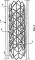
同一参照番号が同一構成部材に言及している図面を参照すると、図1は本発明の一実施形態による血管内ステント搬送システムが参照番号10と概略的に例示された斜視図である。システム10は、カテーテル20、カテーテル20に作動可能に取り付けられたバルーン30、および、バルーン30上に配備されたステント40を備えている。 Referring to the drawings in which like reference numbers refer to like components, FIG. 1 is a perspective view schematically illustrating
図1ではステント40は圧縮形状を呈しているのが例示されているが、血管系の中を前進させられている最中は、通例、バルーンの上などに保持されたままの状態である。圧縮状態のステント40は、血管壁などの面との接触点を最小限にするように、比較的小さい側面(すなわち、縦断面寸法)を有している。ステント40が血管系の内側に適切に設置されてしまうと、バルーン30およびステント40は一緒に拡張される。次に、バルーン30が収縮されてから後退させられることにより、ステント40のみが配備形状で体内に残存することができる。このようなステントの前進、設置、配備などのための各種装置は当該技術で周知である。更に、無数の装置と方法論が本発明によるステントを配備に適した構成にされることを、当業者なら認識するだろう。 In FIG. 1, the
本件で使用されているような「カテーテル」および「ステント」という用語は、血管内装置または移植可能な補綴装置(ステント−グラフト)のいずれか一方、または、その両方をどのような個数でも含んでいてもよいが、本件に提示されている各種実施形態は、本発明と併用する目的に適した構成にされた無数の装置の全部を表すように意図されているものではない。本件に記載されている装置は主として血管内に配備するという文脈でその目的に適した構成にされているが、本発明による血管内装置または移植可能な補綴装置のいずれか一方、または、その両方が胆管、胃腸管、食道、気道などのような上記以外の脈管に配備されてもよいものと認識するべきである。更に、本件で使用されているような「生体分解性」および「生体非分解性」という用語は、生体の体内に設置された場合の相対的な物質安定性に言及したものである。例えば、生体分解性物質は生体非分解性物質よりも高速度で崩壊(すなわち、分解)する。しかしながら、生体非分解性物質は、十分な期間が与えられれば、最終的には崩壊する。 The terms “catheter” and “stent” as used herein include any number of intravascular devices and / or implantable prosthetic devices (stent-grafts). However, the various embodiments presented herein are not intended to represent all of a myriad of devices that are configured to be suitable for use with the present invention. While the devices described herein are configured for that purpose primarily in the context of deployment within a blood vessel, either an intravascular device or an implantable prosthetic device according to the present invention, or both It should be appreciated that may be deployed in other vessels such as the bile duct, gastrointestinal tract, esophagus, airway and the like. Furthermore, the terms “biodegradable” and “non-biodegradable” as used herein refer to the relative material stability when placed in a living body. For example, a biodegradable substance disintegrates (ie, decomposes) at a higher rate than a non-biodegradable substance. However, non-biodegradable materials will eventually disintegrate if given a sufficient period of time.
カテーテル20は1種類以上の重合体素材から製造された細長い管状部材を含んでいることがあり、場合によっては、金属製補強部材と組合わせた上述の管状部材を含んでいてもよい。或る応用例では(例えば、小型のもっと曲がりくねった動脈など)、カテーテルを非常に可撓性に富む材料から構築して難しい接近部位に容易に進入することができるようにするのが望ましい。無数のワイヤ上を伝うカテーテル設計、迅速交換式カテーテル設計、それ以外のカテーテル設計が従来公知であり、本発明と併用する目的に適する構成にされる。カテーテル20は、その近位端で好適なルアー取付部材22に固定されるとともに、丸味付けされた遠位端24が設けられて、血管と有害な接触をするのを緩和するように図っている。カテーテル20は熱可塑性のエラストマー、ウレタン、重合体、ポリプロピレン、プラスチック、エチレン・クロロトリフルオロエチレン(ECTFE)、ポリテトラフルオロエチレン(PTFE)、弗素化エチレン・プロピレンの共重合体(FEP)、ナイロン、ペバックス樹脂(登録商標)(Pebax)、ヴェスタミド・ナイロン(登録商標)(Vestamid)、テコフレックス樹脂(登録商標)(Tecoflex)、ハラール樹脂(登録商標)(Halar)、ハイフロン樹脂(登録商標)(Hyflon)、ぺラセイン樹脂(登録商標)(Pellathane)、これらの各種組合せなどの素材から製造される。カテーテル20は、丸味付けされた遠位端24に開口が形成されており、ガイドワイヤ26の上を伝って前進させることができるようになっている。
バルーン30は、バルーン、または、それ以外の、ステント40を拡張させることが出来る(例えば、外向き放射方向の力を供与することによって)装置であれば、どんな多様なものでもよい。バルーン30は、十分に弾性に富む素材ならば、どんな素材で製造されてもよいが、例えば、ポリエチレン、ポリエチレン・テレフタレート(PET)、ナイロンなどのうちの1つが挙げられる。ステント40は多様な手段を利用して拡張させることができることと、本発明はバルーン拡張法に厳密に限定されないことの両方を、当業者なら認識するだろう。 The balloon 30 can be any variety of balloons or other devices that can expand the stent 40 (eg, by applying an outward radial force). The balloon 30 may be made of any material as long as it is sufficiently elastic, and examples thereof include one of polyethylene, polyethylene terephthalate (PET), and nylon. Those skilled in the art will recognize that the
図2は、ステント40が血管50の内側で配備形状を呈しているのを例示した詳細図である。一実施形態では、ステント40は、概ね管状の本体部が長手方向軸線に沿って延びている通路を定めている。ステント40は少なくとも1個の支柱材(ストラット)42が少なくとも1種類の生体非分解性素材から構成されているが、この事例では2本の支柱材42を備えている。支柱材42はステント40の視覚化(配備支援のための)を向上させるとともに放射方向強度を高め、更には、血管開存性を維持するのを助けることができる。更に、ステント40の視覚化が向上させられたのを利用して、患者の術後措置を支援することもできる。支柱材42に好適な素材として、金属、セラミック、重合体、タンタル、ステンレス鋼、チタニウムASTM F63-83 等級1、ニオブ、ハイカラット金K19-22、MP35N、これらの各種組合せなどが含まれるが、これらに限定されない。一実施形態では、支柱材42は全体が生体非分解性素材から製造されている。また別な実施形態では、支柱材42は生体非分解性素材(例えば、約10パーセント以上)と生体分解性素材の両方から製造されており、その一部が経時的に分解するようにできる。 FIG. 2 is a detailed view illustrating that the
一実施形態では、支柱材42は、生体内の本来の場所においてステント40を視認化し、適切に前進させ、設置し、しかも、配備することができるようにする放射線不透過性材料を含んでいる。当該技術において放射線視認化を目的として使用される多数の素材が支柱材42にも使用することができるが、その具体例として、プラチナ、金、タングステン、金属、金属合金などが含まれる。放射線不透過性素材は、X線透視法、IVUS、これ以外の当該技術で従来公知の各種方法などによって視認化することができる。 In one embodiment, the
一実施形態では、支柱材42は各々が1個の素材片から製造され、「王冠」の形を呈して形成されている。支柱材42は各々がステント40の互いに対向する両端部のうちのそれぞれ一方に隣接して設置されている。また別な実施形態では、支柱材の形状、位置決め、および、数はここに説明および図示されている実施形態とは異なっていてもよい。支柱材(単数または複数)の構成は、その中を通して後の介在処置(例えば、バイパス術、ステント再設置など)を施す妨げとなるのを最小限にするようになっており、しかも、ステント40に構造的支持(すなわち、放射方向の剛性)を供与するのが好ましい。支柱材(単数または複数)は本発明の有用性を制限しないのであれば上記とは異なるものであってもよいことを、当業者なら認識するだろう。 In one embodiment, the
ステント40は、支柱材42に作動可能に取り付けられた生体分解性枠44を更に備えている。一実施形態では、支柱材42は、粘着材(1種類または多数種類)、溶接(1種類または多数種類)、それ以外の、当該技術で従来公知の各種方法を利用して、枠44に接合される。枠44は、適切な強度を与える(例えば、血流の剪断力を克服するような)生体適合性素材で製造されるのが好ましい。枠44に好適な素材としては、セラミック、重合体、これらの各種組合せなどが挙げられるが、これらに限定されない。枠44は、編組繊維、切断管材、ストレートスパンなどとして、或る支柱材42と別な支柱材42の間の隔たり部に跨っている。 The
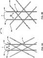
一実施形態では、枠44は多種類の構造的形状を呈して織られており、ステント40の配備中に容易に形の変更を行うことができる。図3Aおよび図3Bに例示されているように、枠44は3方向織りパターン(すなわち、対になって相互に絡み合わされた繊維を3組使う)。このような織りはステント40に与える放射方向強度を比較的大きくすることができる。ステント40の配備中は、バルーンが拡張した結果として枠44が拡張する。より詳細に述べると、拡張は、枠44が拡張するにつれて互いに相関的に増大する、繊維46aと繊維46bの間の角度θ含んでいてもよい。拡張は、繊維46cと繊維46dの間で互いに相関的に増大する間隔Aと両繊維の間で互いに相関的に増大する滑り量のうちいずれか一方、または、その両方を更に含んでいてもよい。また別な実施形態では、枠は構造的な編組、編み物、メッシュなどと、これらとはまた別な織物(例えば、2方向織物)のうちいずれか一方、または、その両方から形成されている。本件発明者らは、本発明による無数の枠形状と枠構成を思量している。 In one embodiment, the
一実施形態では、ステント40は少なくとも1種類の治療薬を1枚以上の被膜の一部として含有している。被膜は支柱材42および枠44の随所に設置される。例えば、1種類以上の治療薬は枠44の繊維46aおよび繊維46bの上に設置される。このように、薬(1種類または多数種類)は、枠44が生体分解するにつれて、血管内皮に搬送される。治療薬被膜は1種類以上の薬剤や重合体などを含有している。例えば、治療薬被膜は1種類の薬剤と1種類の重合体の混合物を含有していることもある。薬剤と重合体の混合物は、当該技術で従来公知のように、生体適合性の液体溶剤中に溶解させられると、ステント枠に塗布するのに好適な溶液を形成する。一例に含まれる或る具体的な薬剤の種類は、抗血管形成剤、抗血管内皮細胞由来ペプチド剤、抗炎症剤、抗分裂促進因子剤、抗酸化剤、抗血小板剤、抗増殖剤、アンチセンスオリゴヌクレオチド、カルシウムチャネル遮断薬、血餅溶解酵素、成長因子、成長因子阻害薬、硝酸、酸化窒素放出剤、血管拡張剤、ウイルスを薬用化した遺伝子転移剤、所望の治療適用を有する薬剤などがある。 In one embodiment, the
各種薬剤および各種重合体の性質は互いに大いに異なっており、また、所与の治療効果を達成するように製剤されるのが通例であり、治療効果の具体例として再狭窄の抑制、血栓形成の抑制、肥厚の抑制などが挙げられることを、当業者なら認識するだろう。製剤が行われてしまうと、被膜(1枚または複数枚)を含んでいる治療薬(混合薬)が当該技術で従来公知の多数の医療戦略のうちのいずれかによってステントに塗布されるが、このような医療戦略の具体例として、噴霧、浸漬、回転塗布、ノズル噴射などが挙げられるが、これらに限定されない。これに代わる例として、所望の効果次第で少なくとも1種類の治療薬被膜がステント上とステント内側の両方に層形成され、配置され、構築されるのが認識されるだろう。塗布前に、1種類以上のプライマがステントに下塗りされて、少なくとも1種類の治療薬被膜の粘着を容易にすることができる。少なくとも1種類の治療薬被膜液が塗布されてしまうと、治療薬(1種類または複数種類)が乾燥させられてから(すなわち、溶剤を蒸発させることができるようにすることによって)、任意で、また別な被膜(1枚または複数枚)(例えば、「帽子状」被膜など)がその上に添加される。本発明に従ってプライマ、治療薬被膜(1枚または複数枚)、および、帽子状被膜(1枚または複数枚)を塗布するという多数の医療戦略は当該技術で従来公知である。 The properties of various drugs and various polymers are very different from each other, and are usually formulated to achieve a given therapeutic effect. Specific examples of therapeutic effects include suppression of restenosis and thrombus formation. Those skilled in the art will recognize that suppression, suppression of thickening and the like can be mentioned. Once the formulation has been performed, the therapeutic agent (mixed drug) containing the coating (s) is applied to the stent by any of a number of medical strategies conventionally known in the art, Specific examples of such a medical strategy include, but are not limited to, spraying, dipping, spin coating, and nozzle injection. As an alternative example, it will be appreciated that at least one therapeutic agent coating is layered, placed and constructed both on the stent and inside the stent depending on the desired effect. Prior to application, one or more primers can be primed to the stent to facilitate adhesion of the at least one therapeutic agent coating. Once at least one therapeutic agent coating has been applied, after the therapeutic agent (s) have been dried (ie, by allowing the solvent to evaporate), optionally, Another coating (one or more) (eg, a “hat-like” coating) is added thereon. Numerous medical strategies are conventionally known in the art to apply a primer, therapeutic agent coating (s), and cap-like coating (s) in accordance with the present invention.
本件の明細書を読んで図面を再検討すると、これ以外の本発明の実施形態は無数に考えることができること、また、そのような実施形態は予想されたものであり、本件添付の特許請求の範囲に記載されている発明の範囲に入ることを、当業者なら直ちに看破するだろう。本発明の範囲は添付の特許請求の範囲に示されており、それらの均等物の意味と範囲に入る変更は全て、本発明に包含されるものと意図されている。 Upon reviewing the specification and reviewing the drawings, numerous other embodiments of the invention can be considered, and such embodiments are anticipated, and the appended claims Those skilled in the art will immediately recognize that they are within the scope of the invention described in the scope. The scope of the invention is indicated in the appended claims, and all changes that come within the meaning and range of equivalents are intended to be embraced therein.
本件に開示されている本発明の各種実施形態を本件では好ましいと見なされているが、本発明の真髄および範囲から逸脱せずに、多数の変更および修正を行うことができる。例えば、血管内装置はどの特定の設計にも限定されず、例えば、ステントに限定されない。さらに、支柱材(単数または複数)、枠、および、支柱材と枠のそれぞれの構成は、機能的な生体分解性装置と生体非分解性装置との混成装置を供与するが、変更することができる。 While the various embodiments of the invention disclosed herein are considered to be preferred herein, numerous changes and modifications may be made without departing from the spirit and scope of the invention. For example, the intravascular device is not limited to any particular design, for example, it is not limited to a stent. Further, the strut material (s), the frame, and each configuration of the strut material and the frame provide a hybrid device of functional biodegradable and non-biodegradable devices, but may be changed. it can.
Claims (7)
Translated fromJapanese生体分解性素材から構成されている枠(44)と、
生体非分解性素材から構成されている少なくとも1本の支柱部材(42)と、を備え、
前記枠(44)は、前記少なくとも1本の支柱部材(42)に動作可能に取り付けられ、
前記少なくとも1本の支柱部材(42)は、構造支持部を含み、
前記構造支持部は、冠形状を有している、
ことを特徴とするステント。An endovascular stent (40) comprising:
A frame (44) composed of a biodegradable material;
And at least one strut member (42) made of a non-biodegradable material,
Said frame (44), said operatively mounted et alis in at least one strut member(42),
The at least one strut member (42) includes a structural support;
The structural support has a crown shape;
A stent characterized by that.
請求項1に記載のステント。At least one therapeutic agent is located at a location on the device,
The stent according to claim 1.
請求項1に記載のステント。The frame (44) includes at least one of a braided pattern, a knitted pattern, a mesh pattern, and a woven pattern,
The stent according to claim 1.
請求項1に記載のステント。The frame (44) extends during device deployment,
The stent according to claim 1.
カテーテル(20)と、
請求項1から6のいずれか1項に記載のステント(40)とを備え、前記ステント(40)は、前記カテーテル(20)の一部分に配置されている、
ことを特徴とする、血管内ステント搬送システム。An intravascular stent delivery system (10) comprising:
A catheter (20);
A stent (40) according to any one of claims 1 to6 , wherein the stent (40) is disposed on a portion of the catheter (20).
An intravascular stent delivery system.
Applications Claiming Priority (3)
| Application Number | Priority Date | Filing Date | Title |
|---|---|---|---|
| US66528905P | 2005-03-24 | 2005-03-24 | |
| US60/665,289 | 2005-03-24 | ||
| PCT/US2006/008124WO2006104648A2 (en) | 2005-03-24 | 2006-03-07 | Hybrid biodegradable/non-biodegradable stent, delivery system and method of treating a vascular condition |
Publications (3)
| Publication Number | Publication Date |
|---|---|
| JP2008534052A JP2008534052A (en) | 2008-08-28 |
| JP2008534052A5 JP2008534052A5 (en) | 2009-04-23 |
| JP4824747B2true JP4824747B2 (en) | 2011-11-30 |
Family
ID=36838519
Family Applications (1)
| Application Number | Title | Priority Date | Filing Date |
|---|---|---|---|
| JP2008503009AExpired - Fee RelatedJP4824747B2 (en) | 2005-03-24 | 2006-03-07 | Intravascular stent and intravascular stent delivery system |
Country Status (4)
| Country | Link |
|---|---|
| US (1) | US9056157B2 (en) |
| EP (1) | EP1871439B1 (en) |
| JP (1) | JP4824747B2 (en) |
| WO (1) | WO2006104648A2 (en) |
Families Citing this family (30)
| Publication number | Priority date | Publication date | Assignee | Title |
|---|---|---|---|---|
| WO2003002243A2 (en) | 2001-06-27 | 2003-01-09 | Remon Medical Technologies Ltd. | Method and device for electrochemical formation of therapeutic species in vivo |
| US9125732B2 (en) | 2005-07-25 | 2015-09-08 | Vascular Dynamics, Inc. | Devices and methods for control of blood pressure |
| US9592136B2 (en) | 2005-07-25 | 2017-03-14 | Vascular Dynamics, Inc. | Devices and methods for control of blood pressure |
| US8923972B2 (en)* | 2005-07-25 | 2014-12-30 | Vascular Dynamics, Inc. | Elliptical element for blood pressure reduction |
| WO2010035271A1 (en) | 2008-09-26 | 2010-04-01 | Vascular Dynamics Inc. | Devices and methods for control of blood pressure |
| US9642726B2 (en) | 2005-07-25 | 2017-05-09 | Vascular Dynamics, Inc. | Devices and methods for control of blood pressure |
| US8840660B2 (en) | 2006-01-05 | 2014-09-23 | Boston Scientific Scimed, Inc. | Bioerodible endoprostheses and methods of making the same |
| US8089029B2 (en) | 2006-02-01 | 2012-01-03 | Boston Scientific Scimed, Inc. | Bioabsorbable metal medical device and method of manufacture |
| US8048150B2 (en) | 2006-04-12 | 2011-11-01 | Boston Scientific Scimed, Inc. | Endoprosthesis having a fiber meshwork disposed thereon |
| EP2054537A2 (en) | 2006-08-02 | 2009-05-06 | Boston Scientific Scimed, Inc. | Endoprosthesis with three-dimensional disintegration control |
| ES2357661T3 (en) | 2006-09-15 | 2011-04-28 | Boston Scientific Scimed, Inc. | BIOEROSIONABLE ENDOPROOTHESIS WITH BIOESTABLE INORGANIC LAYERS. |
| JP2010503489A (en) | 2006-09-15 | 2010-02-04 | ボストン サイエンティフィック リミテッド | Biodegradable endoprosthesis and method for producing the same |
| EP2959925B1 (en) | 2006-09-15 | 2018-08-29 | Boston Scientific Limited | Medical devices and methods of making the same |
| WO2008034066A1 (en) | 2006-09-15 | 2008-03-20 | Boston Scientific Limited | Bioerodible endoprostheses and methods of making the same |
| WO2008036548A2 (en) | 2006-09-18 | 2008-03-27 | Boston Scientific Limited | Endoprostheses |
| ES2506144T3 (en) | 2006-12-28 | 2014-10-13 | Boston Scientific Limited | Bioerodible endoprosthesis and their manufacturing procedure |
| US8052745B2 (en) | 2007-09-13 | 2011-11-08 | Boston Scientific Scimed, Inc. | Endoprosthesis |
| US8118857B2 (en) | 2007-11-29 | 2012-02-21 | Boston Scientific Corporation | Medical articles that stimulate endothelial cell migration |
| US7998192B2 (en) | 2008-05-09 | 2011-08-16 | Boston Scientific Scimed, Inc. | Endoprostheses |
| US8236046B2 (en) | 2008-06-10 | 2012-08-07 | Boston Scientific Scimed, Inc. | Bioerodible endoprosthesis |
| US7985252B2 (en) | 2008-07-30 | 2011-07-26 | Boston Scientific Scimed, Inc. | Bioerodible endoprosthesis |
| US8382824B2 (en) | 2008-10-03 | 2013-02-26 | Boston Scientific Scimed, Inc. | Medical implant having NANO-crystal grains with barrier layers of metal nitrides or fluorides |
| EP2403546A2 (en) | 2009-03-02 | 2012-01-11 | Boston Scientific Scimed, Inc. | Self-buffering medical implants |
| US8668732B2 (en) | 2010-03-23 | 2014-03-11 | Boston Scientific Scimed, Inc. | Surface treated bioerodible metal endoprostheses |
| US9326870B2 (en) | 2010-04-23 | 2016-05-03 | Medtronic Vascular, Inc. | Biodegradable stent having non-biodegradable end portions and mechanisms for increased stent hoop strength |
| US9320628B2 (en) | 2013-09-09 | 2016-04-26 | Boston Scientific Scimed, Inc. | Endoprosthesis devices including biostable and bioabsorable regions |
| JP2016116633A (en)* | 2014-12-19 | 2016-06-30 | テルモ株式会社 | Wire braiding type stent and manufacturing method thereof |
| JP6963566B2 (en) | 2016-05-16 | 2021-11-10 | エリクシアー メディカル コーポレイション | Uncaging stent |
| US11622872B2 (en) | 2016-05-16 | 2023-04-11 | Elixir Medical Corporation | Uncaging stent |
| EP3664752B1 (en) | 2017-08-11 | 2024-07-03 | Elixir Medical Corporation | Uncaging stent |
Citations (3)
| Publication number | Priority date | Publication date | Assignee | Title |
|---|---|---|---|---|
| JPH0464367A (en)* | 1990-07-03 | 1992-02-28 | Olympus Optical Co Ltd | Expander for vital duct |
| JP2004166807A (en)* | 2002-11-18 | 2004-06-17 | Sumitomo Bakelite Co Ltd | Stent |
| JP2004528115A (en)* | 2001-05-03 | 2004-09-16 | バイオンクス インプランツ インコーポレイテッド | Method of connecting an axially extending filament to a self-expanding stent |
Family Cites Families (19)
| Publication number | Priority date | Publication date | Assignee | Title |
|---|---|---|---|---|
| SE445884B (en)* | 1982-04-30 | 1986-07-28 | Medinvent Sa | DEVICE FOR IMPLANTATION OF A RODFORM PROTECTION |
| WO1993006792A1 (en)* | 1991-10-04 | 1993-04-15 | Scimed Life Systems, Inc. | Biodegradable drug delivery vascular stent |
| US5500013A (en)* | 1991-10-04 | 1996-03-19 | Scimed Life Systems, Inc. | Biodegradable drug delivery vascular stent |
| US5629077A (en)* | 1994-06-27 | 1997-05-13 | Advanced Cardiovascular Systems, Inc. | Biodegradable mesh and film stent |
| US5670161A (en)* | 1996-05-28 | 1997-09-23 | Healy; Kevin E. | Biodegradable stent |
| US5868782A (en)* | 1996-12-24 | 1999-02-09 | Global Therapeutics, Inc. | Radially expandable axially non-contracting surgical stent |
| US5843175A (en)* | 1997-06-13 | 1998-12-01 | Global Therapeutics, Inc. | Enhanced flexibility surgical stent |
| US6245103B1 (en)* | 1997-08-01 | 2001-06-12 | Schneider (Usa) Inc | Bioabsorbable self-expanding stent |
| US6042606A (en)* | 1997-09-29 | 2000-03-28 | Cook Incorporated | Radially expandable non-axially contracting surgical stent |
| DE59913189D1 (en)* | 1998-06-25 | 2006-05-04 | Biotronik Ag | Implantable, bioabsorbable vessel wall support, in particular coronary stent |
| EP1033145B1 (en)* | 1998-09-08 | 2014-12-17 | Kabushikikaisha Igaki Iryo Sekkei | Stent for vessels |
| US6338739B1 (en)* | 1999-12-22 | 2002-01-15 | Ethicon, Inc. | Biodegradable stent |
| US6656216B1 (en)* | 2001-06-29 | 2003-12-02 | Advanced Cardiovascular Systems, Inc. | Composite stent with regioselective material |
| JP4512369B2 (en)* | 2002-01-31 | 2010-07-28 | ラディ・メディカル・システムズ・アクチェボラーグ | Stent |
| US20030153971A1 (en)* | 2002-02-14 | 2003-08-14 | Chandru Chandrasekaran | Metal reinforced biodegradable intraluminal stents |
| US20030195609A1 (en)* | 2002-04-10 | 2003-10-16 | Scimed Life Systems, Inc. | Hybrid stent |
| US20050165469A1 (en)* | 2002-12-24 | 2005-07-28 | Michael Hogendijk | Vascular prosthesis including torsional stabilizer and methods of use |
| US7632299B2 (en)* | 2004-01-22 | 2009-12-15 | Boston Scientific Scimed, Inc. | Medical devices |
| US20050222671A1 (en)* | 2004-03-31 | 2005-10-06 | Schaeffer Darin G | Partially biodegradable stent |
- 2006
- 2006-03-07JPJP2008503009Apatent/JP4824747B2/ennot_activeExpired - Fee Related
- 2006-03-07WOPCT/US2006/008124patent/WO2006104648A2/enactiveApplication Filing
- 2006-03-07EPEP06737309Apatent/EP1871439B1/ennot_activeNot-in-force
- 2006-03-07USUS11/909,297patent/US9056157B2/enactiveActive
Patent Citations (3)
| Publication number | Priority date | Publication date | Assignee | Title |
|---|---|---|---|---|
| JPH0464367A (en)* | 1990-07-03 | 1992-02-28 | Olympus Optical Co Ltd | Expander for vital duct |
| JP2004528115A (en)* | 2001-05-03 | 2004-09-16 | バイオンクス インプランツ インコーポレイテッド | Method of connecting an axially extending filament to a self-expanding stent |
| JP2004166807A (en)* | 2002-11-18 | 2004-06-17 | Sumitomo Bakelite Co Ltd | Stent |
Also Published As
| Publication number | Publication date |
|---|---|
| WO2006104648A3 (en) | 2006-12-07 |
| EP1871439A2 (en) | 2008-01-02 |
| WO2006104648A2 (en) | 2006-10-05 |
| JP2008534052A (en) | 2008-08-28 |
| EP1871439B1 (en) | 2012-05-30 |
| US9056157B2 (en) | 2015-06-16 |
| US20090306756A1 (en) | 2009-12-10 |
Similar Documents
| Publication | Publication Date | Title |
|---|---|---|
| JP4824747B2 (en) | Intravascular stent and intravascular stent delivery system | |
| JP6434574B2 (en) | Stent | |
| US9339630B2 (en) | Retractable drug delivery system and method | |
| US9962274B2 (en) | Stretchable stent and delivery | |
| JP5432909B2 (en) | In-vivo stent and stent delivery system | |
| US20080269869A1 (en) | Intraluminal Stent, Delivery System, and Method of Treating a Vascular Condition | |
| US20100125325A1 (en) | Stent With Cathodic Protection and Stent Delivery System | |
| US20080039920A1 (en) | Tethered Self-Expanding Stent Delivery System | |
| JP2005511140A (en) | Apparatus and method for delivering a mesh prosthesis | |
| JP2008529719A (en) | Delivery system for self-expanding stents, method of using the delivery system and method of manufacturing the delivery system | |
| WO2006125022A2 (en) | Medical devices including metallic films and methods for making same | |
| JP2009542352A (en) | Stent with radiopaque marker and method for manufacturing the same | |
| US20080039928A1 (en) | Slotted Self-Expanding Stent Delivery System | |
| JP3625495B2 (en) | Luminal organ treatment device | |
| US20080039924A1 (en) | Channeled Self-Expanding Stent Delivery System | |
| EP1827303B1 (en) | Vulnerable plaque stent | |
| US20070067020A1 (en) | Intraluminal stent, delivery system, and a method of treating a vascular condition | |
| EP1948081B1 (en) | Intraluminal stent, delivery system, and method of treating a vascular condition | |
| CN117942206B (en) | A recyclable drug delivery system and its application | |
| JP5847160B2 (en) | Stent and stent delivery system | |
| US20100168833A1 (en) | Stent With Reduced Profile, Delivery System, and Method of Manufacture | |
| WO2008018869A1 (en) | Stent delivery devices, systems & methods |
Legal Events
| Date | Code | Title | Description |
|---|---|---|---|
| A521 | Request for written amendment filed | Free format text:JAPANESE INTERMEDIATE CODE: A523 Effective date:20090306 | |
| A621 | Written request for application examination | Free format text:JAPANESE INTERMEDIATE CODE: A621 Effective date:20090306 | |
| A131 | Notification of reasons for refusal | Free format text:JAPANESE INTERMEDIATE CODE: A131 Effective date:20110509 | |
| A977 | Report on retrieval | Free format text:JAPANESE INTERMEDIATE CODE: A971007 Effective date:20110512 | |
| A521 | Request for written amendment filed | Free format text:JAPANESE INTERMEDIATE CODE: A523 Effective date:20110808 | |
| TRDD | Decision of grant or rejection written | ||
| A01 | Written decision to grant a patent or to grant a registration (utility model) | Free format text:JAPANESE INTERMEDIATE CODE: A01 Effective date:20110905 | |
| A01 | Written decision to grant a patent or to grant a registration (utility model) | Free format text:JAPANESE INTERMEDIATE CODE: A01 | |
| A61 | First payment of annual fees (during grant procedure) | Free format text:JAPANESE INTERMEDIATE CODE: A61 Effective date:20110908 | |
| R150 | Certificate of patent or registration of utility model | Free format text:JAPANESE INTERMEDIATE CODE: R150 | |
| FPAY | Renewal fee payment (event date is renewal date of database) | Free format text:PAYMENT UNTIL: 20140916 Year of fee payment:3 | |
| R250 | Receipt of annual fees | Free format text:JAPANESE INTERMEDIATE CODE: R250 | |
| LAPS | Cancellation because of no payment of annual fees |