JP4821409B2 - Hydraulic control device for automatic transmission - Google Patents
Hydraulic control device for automatic transmissionDownload PDFInfo
- Publication number
- JP4821409B2 JP4821409B2JP2006099837AJP2006099837AJP4821409B2JP 4821409 B2JP4821409 B2JP 4821409B2JP 2006099837 AJP2006099837 AJP 2006099837AJP 2006099837 AJP2006099837 AJP 2006099837AJP 4821409 B2JP4821409 B2JP 4821409B2
- Authority
- JP
- Japan
- Prior art keywords
- control
- hydraulic
- hydraulic pressure
- pressure
- automatic transmission
- Prior art date
- Legal status (The legal status is an assumption and is not a legal conclusion. Google has not performed a legal analysis and makes no representation as to the accuracy of the status listed.)
- Expired - Fee Related
Links
- 230000005540biological transmissionEffects0.000titleclaimsdescription40
- 230000001133accelerationEffects0.000claimsdescription8
- 238000010408sweepingMethods0.000claimsdescription7
- 230000035939shockEffects0.000description7
- 238000001514detection methodMethods0.000description6
- 230000006870functionEffects0.000description5
- 238000007664blowingMethods0.000description3
- 238000010586diagramMethods0.000description3
- 230000004913activationEffects0.000description2
- 230000001276controlling effectEffects0.000description2
- 239000002783friction materialSubstances0.000description2
- 230000001105regulatory effectEffects0.000description2
- 238000005452bendingMethods0.000description1
- 230000033228biological regulationEffects0.000description1
- 230000001419dependent effectEffects0.000description1
Images


Classifications
- F—MECHANICAL ENGINEERING; LIGHTING; HEATING; WEAPONS; BLASTING
- F16—ENGINEERING ELEMENTS AND UNITS; GENERAL MEASURES FOR PRODUCING AND MAINTAINING EFFECTIVE FUNCTIONING OF MACHINES OR INSTALLATIONS; THERMAL INSULATION IN GENERAL
- F16H—GEARING
- F16H61/00—Control functions within control units of change-speed- or reversing-gearings for conveying rotary motion ; Control of exclusively fluid gearing, friction gearing, gearings with endless flexible members or other particular types of gearing
- F16H61/04—Smoothing ratio shift
- F16H61/06—Smoothing ratio shift by controlling rate of change of fluid pressure
- F16H61/061—Smoothing ratio shift by controlling rate of change of fluid pressure using electric control means
- F—MECHANICAL ENGINEERING; LIGHTING; HEATING; WEAPONS; BLASTING
- F16—ENGINEERING ELEMENTS AND UNITS; GENERAL MEASURES FOR PRODUCING AND MAINTAINING EFFECTIVE FUNCTIONING OF MACHINES OR INSTALLATIONS; THERMAL INSULATION IN GENERAL
- F16H—GEARING
- F16H61/00—Control functions within control units of change-speed- or reversing-gearings for conveying rotary motion ; Control of exclusively fluid gearing, friction gearing, gearings with endless flexible members or other particular types of gearing
- F16H2061/0075—Control functions within control units of change-speed- or reversing-gearings for conveying rotary motion ; Control of exclusively fluid gearing, friction gearing, gearings with endless flexible members or other particular types of gearing characterised by a particular control method
- F16H2061/0087—Adaptive control, e.g. the control parameters adapted by learning
- F—MECHANICAL ENGINEERING; LIGHTING; HEATING; WEAPONS; BLASTING
- F16—ENGINEERING ELEMENTS AND UNITS; GENERAL MEASURES FOR PRODUCING AND MAINTAINING EFFECTIVE FUNCTIONING OF MACHINES OR INSTALLATIONS; THERMAL INSULATION IN GENERAL
- F16H—GEARING
- F16H61/00—Control functions within control units of change-speed- or reversing-gearings for conveying rotary motion ; Control of exclusively fluid gearing, friction gearing, gearings with endless flexible members or other particular types of gearing
- F16H61/68—Control functions within control units of change-speed- or reversing-gearings for conveying rotary motion ; Control of exclusively fluid gearing, friction gearing, gearings with endless flexible members or other particular types of gearing specially adapted for stepped gearings
- F16H61/684—Control functions within control units of change-speed- or reversing-gearings for conveying rotary motion ; Control of exclusively fluid gearing, friction gearing, gearings with endless flexible members or other particular types of gearing specially adapted for stepped gearings without interruption of drive
- F16H61/686—Control functions within control units of change-speed- or reversing-gearings for conveying rotary motion ; Control of exclusively fluid gearing, friction gearing, gearings with endless flexible members or other particular types of gearing specially adapted for stepped gearings without interruption of drive with orbital gears
Landscapes
- Engineering & Computer Science (AREA)
- General Engineering & Computer Science (AREA)
- Physics & Mathematics (AREA)
- Fluid Mechanics (AREA)
- Mechanical Engineering (AREA)
- Control Of Transmission Device (AREA)
Description
Translated fromJapanese本発明は、自動車に搭載される自動変速機の油圧制御装置に係り、詳しくは一方の摩擦係合要素が係合すると共に他方の摩擦係合要素が解放して所定変速段に変速する、いわゆるクラッチツークラッチ(つかみ換え)変速、特にアップシフト時のクラッチツークラッチ変速における油圧制御装置に関する。The present invention relates to a hydraulic control device for an automatic transmission mounted on an automobile. Specifically, one friction engagement element is engaged and the other friction engagement element is released to shift to a predetermined gearstage. The present invention relates to a hydraulic control apparatus for clutch-to-clutch (shifting) shifting, particularly clutch-to-clutch shifting during upshifting.
一般に、自動変速機は、車速及びアクセル開度により変速段が指令され、該指令された変速段になるように、クラッチツークラッチにより変速機構の伝動経路が変更される。 Generally, in an automatic transmission, a gear position is commanded by the vehicle speed and the accelerator opening, and the transmission path of the speed change mechanism is changed by the clutch-to-clutch so that the commanded gear speed is achieved.
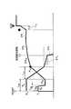
従来、上記クラッチツークラッチ変速の油圧制御装置として、下記特許文献1に示されるものがある。該油圧制御装置によるアップシフト時の油圧変化を図7に示す。図7において、PAは、係合側となる(第1の)摩擦係合要素用油圧の指令値(以下係合側油圧という)であり、PBは、解放側となる(第2の)摩擦係合要素用油圧の指令値(以下解放側油圧という)であり、共に制御部から調圧手段であるリニアソレノイドバルブに出力する。なお、符号は、本発明の実施の形態について説明する図3(a)と同じものであって、詳しくは図3(a)にて後述する。Conventionally, as a hydraulic control device for clutch-to-clutch shift, there is one disclosed in
係合側油圧PAは、第1の摩擦係合要素のガタを詰めるためにピストンをストロークするサーボ起動制御の後、入力トルクに応じて、イナーシャ相が開始する直前の状態の目標油圧PTAに向って所定勾配でスイープする第1のスイープ制御と、該目標油圧から前記所定勾配よりも緩やかな勾配δPTAでスイープする第2のスイープ制御により上昇する(トルク相制御)。該油圧上昇により入力回転数が変化すると、イナーシャ制御となり、入力回転数の変化量によりフードバック制御されつつスイープアップし、変速が完了に近づいた状態で油圧を高い勾配で上昇し(完了制御)、変速が完了する。The engagement hydraulic pressure PA, after the servo starting control for the stroke of the piston in order to pack the backlash of the first frictional engagement element, in accordance with the input torque, the state immediately before the inertia phase begins target pressure PTA And a second sweep control that sweeps from the target hydraulic pressure with a gradient δPTA that is gentler than the predetermined gradient (torque phase control). When the input rotation speed changes due to the increase in oil pressure, inertia control is performed, and the hood back is swept up by the amount of change in the input rotation speed, and the oil pressure rises with a high gradient in the state where the shift is nearing completion (completion control). The shifting is completed.
一方、解放側油圧PBは、係合側油圧PA及び入力トルクの関数により算出され、係合側油圧PAの上昇に依存してスイープダウンする。従って、サーボ起動制御後、係合側油圧PAの目標油圧PTAへ向う第1のスイープ制御に対応した所定勾配でスイープダウンし、該目標油圧PTA後の第2のスイープ制御に対応して、上記所定勾配より緩やかな勾配δPCにてスイープダウンする。そして、イナーシャ制御に入ると、比較的急勾配δPE1でスイープダウンして解放側油圧PBが0になる。On the other hand, the release-side hydraulic pressure PB is calculated by a function of the engagement hydraulic pressure PA and the input torque, it sweeps down depending on the increase of the engagement side hydraulic pressure PA. Therefore, after the servo starting control, swept down at a predetermined gradient corresponding to the first sweep control toward the target pressure PTA of the engagement side hydraulic pressure PA, corresponding to the second sweep control after the target hydraulic pressure PTA Te, sweep down at gentle gradient [delta] PC than the predetermined gradient. Then, when the inertia control is entered, the release side hydraulic pressure PB becomes 0 by sweeping down at a relatively steep slope δPE1 .
上述した解放側油圧PBは、エンジンの吹き上りを防止するため、係合側油圧の第2のスイープ制御に依存して所定勾配δPCでスイープダウンしているため、入力回転数が回転変化した状態では、通常では解放側油圧PBが実質的に抜けている。したがって、回転変化を生じさせるのは、係合側油圧PAのみであるため、トルク相の時間の短縮を狙って、係合側油圧の勾配を高くしていると、図8に示すように、イナーシャ相開始直後に出力軸トルクTOが大きく変動してイナーシャショックを発生する場合がある。Disengagement side pressure PB described above, in order to prevent the blowing up of the engine, because it swept down at a predetermined gradient [delta] PC, depending on the second sweep control of the engagement side hydraulic rotation changes the input rotation speed In this state, normally, the release side hydraulic pressure PB is substantially lost. Thus, the causes rotation changes, since only the engagement hydraulic pressure PA, aimed at reducing the time of the torque phase and have higher gradient of the engagement-side oil pressure, as shown in FIG. 8 , it may occur inertia shock vary the output shaft torque TO is large just after the beginning of the inertia phase.
本発明は、上記第2のスイープ制御に対応する解放側油圧制御手段の制御を一部変更して、エンジン吹きを防止しつつ、イナーシャショックの発生を防止する、自動変速機の油圧制御装置を提供することを目的とするものである。 The present invention provides a hydraulic control device for an automatic transmission that changes the control of the release side hydraulic control means corresponding to the second sweep control to prevent the occurrence of inertia shock while preventing engine blow. It is intended to provide.
本発明は、入力軸と出力軸との間で動力伝達経路を変更する複数の摩擦係合要素と、これら摩擦係合要素を断・接作動する油圧サーボと、を備え、前記複数の摩擦係合要素の内の第1の摩擦係合要素を係合すると共に、第2の摩擦係合要素を解放することにより所定変速段へのアップシフトを達成してなり、
少なくとも前記第1及び第2の摩擦係合要素用油圧サーボ(9)(10)の油圧を制御する油圧操作手段と、車輌走行状況に基づく各センサ(2〜8)からの信号を入力して、前記油圧操作手段(SLU)(SLS)へ油圧制御信号を出力する制御部(1)と、を備えてなる自動変速機の油圧制御装置において、
前記制御部(1)は、前記第1の摩擦係合要素用油圧サーボ(9)への油圧変化を算出して前記油圧操作手段(SLU)に出力する係合側油圧制御手段(1a)と、前記第2の摩擦係合要素用油圧サーボ(10)への油圧を算出して前記油圧操作手段(SLS)に出力する解放側油圧制御手段(1b)と、を有し、
前記解放側油圧制御手段(1b)は、トルク相において、前記係合側油圧制御手段(1a)による係合側油圧(PA)に依存して算出され、前記第2の摩擦係合要素が微小トルク容量を有する所定解放側油圧(PB≦fPB(0)+PKEEP+PLS2T)までスイープダウンする初期制御(B)と、該初期制御後、前記トルク相に続くイナーシャ相の開始を検出するまで、実質的に前記所定解放側油圧を保持するように制御する保持制御(C)と、を備え、
前記所定解放側油圧は、前記第2の摩擦係合要素の分担トルク(TB)が微小トルクに相当する油圧(fPB(0))と、マップにより選択される目標保持圧補正項(PKEEP)と、学習制御により設定される油圧(PLS2T)との和からなる、
ことを特徴とする自動変速機の油圧制御装置にある。The present invention comprises a plurality of friction engagement elements that change a power transmission path between an input shaft and an output shaft, and a hydraulic servo that operates to disconnect and engage these friction engagement elements. Engaging the first frictional engagement element of the combined element and releasing the second frictional engagement element to achieve an upshift to a predetermined gear stage;
Input signals from the hydraulic operation means for controlling the hydraulic pressure of at least the first and second friction engagement element hydraulic servos (9) and (10), and the sensors (2 to 8) based on the vehicle running condition. A control unit (1) for outputting a hydraulic control signal to the hydraulic operating means (SLU) (SLS), and a hydraulic control device for an automatic transmission comprising:
The control unit (1) calculates an oil pressure change to the first friction engagement element hydraulic servo (9) and outputs it to the hydraulic operation means (SLU) and an engagement side hydraulic control means (1a). A release-side hydraulic control means (1b) for calculating a hydraulic pressure to the second friction engagement element hydraulic servo (10) and outputting the hydraulic pressure to the hydraulic operation means (SLS).
The release side hydraulic control means (1b) is calculated depending on the engagement side hydraulic pressure (PA ) by the engagement side hydraulic control means (1a) in the torque phase, and the second friction engagement element is Initial control (B) for sweeping down to a predetermined release side hydraulic pressure (PB ≦ fPB (0) + PKEEP + PLS2T ) having a minute torque capacity, and detecting the start of the inertia phase following the torque phase after the initial control until, Beiexample substantially the predeterminedrelease-side holding control for controlling so as to hold the hydraulic (C), anda,
The predetermined release side hydraulic pressure includesa hydraulic pressure (fPB(0))corresponding to a minute torque ofthe second friction engagement element (TB) and a target holding pressure correction term (PKEEP) and the hydraulic pressure (PLS2T)set by learning control,
The hydraulic control device for an automatic transmission is characterized by the above.
前記学習制御により設定される油圧(PLS2T)は、入力回転数(NT)の加速度と前記入力回転数の変化開始までの時間により補正される値である。
前記目標保持圧補正項(PKEEP)は、各変速段において選択される入力トルクに応じて設定されてなる。The hydraulic pressure (PLS2T)set by the learning controlis a value that is corrected by the accelerationof the input rotation speed (NT) and the time until the input rotation speed starts to change .
The target holding pressure correction term (PKEEP) is set according to the input torque selected at each gear.
前記保持制御(C)が、極めて緩い勾配(δPB)でスイープダウンしてなる。Before SL holding control (C) is formed by sweeping down in a very gentle gradient (δPB).
前記解放側油圧制御手段(1b)は、前記保持制御(C)後(即ち終期制御D)、前記係合側油圧制御手段(1a)のイナーシャ相制御が終了するまでの間で、解放側油圧(PB)が0になるような緩勾配(δPE2)でのスイープダウンする緩勾配スイープダウン制御を有する。Before SL disengagement side hydraulic control means (1b) is between to the holding control (C) after (i.e. final control D), the inertia phase control of the engagement side hydraulic control means (1a) is finished, release side Slow gradient sweep down control is performed to sweep down at a gentle gradient (δPE2 ) such that the hydraulic pressure (PB ) becomes zero.
前記解放側油圧制御手段(1b)は、前記保持制御(C)後、前記緩勾配スイープダウン制御の前記緩勾配(δPE2)より急な勾配(δPE1)でスイープダウンする急勾配スイープダウン制御を有し、
前記緩勾配スイープダウン制御と前記急勾配スイープダウン制御のいずれか一方を選択してなる。Before SL disengagement side hydraulic control means (1b), the holding control (C) after, steep sweep-down sweeping down from steep slope ([delta] PE1) the gentle slope of the low-gradient sweep-down control ([delta] PE2) Have control,
One of the gentle gradient sweep down control and the steep gradient sweep down control is selected.
前記自動変速機は、自動変速モードと、手動変速モードとを備え、
前記自動変速モードにあっては前記緩勾配スイープダウン制御(δPE2)が選択され、
前記手動変速モードにあっては前記急勾配スイープダウン制御(δPE1)が選択されてなる。Before Symbol automatic transmission is equipped with an automatic shift mode and a manual shift mode,
In the automatic transmission mode, the gentle gradient sweep down control (δPE2 ) is selected,
In the manual shift mode, the steep slope sweep down control (δPE1 ) is selected.
前記係合側油圧制御手段(1a)は、イナーシャ相が開始する直前の状態の目標油圧(PTA)まで第1の勾配でスイープアップする第1のスイープ制御と、前記目標油圧(PTA)から前記入力回転数の回転変化を検出するまで(ΔN≧dNS)、前記第1の勾配より緩やかな第2の勾配によりスイープアップする第2のスイープ制御と、を有し、
前記解放側油圧制御手段の前記初期制御(B)が、前記第1のスイープ制御の係合側油圧に依存して算出されてなる。Before Kigakarigo side hydraulic control means (1a) has a first sweep control sweeping up the first slope to the target hydraulic pressure (PTA) in a state immediately before the inertia phase begins, the target hydraulic pressure (PTA ) Until a change in the rotational speed of the input rotation is detected (ΔN ≧ dNS ), and a second sweep control that sweeps up with a second gradient that is gentler than the first gradient,
The initial control (B) of the release side hydraulic control means is calculated depending on the engagement side hydraulic pressure of the first sweep control.
なお、上記カッコ内の符号は、図面と対照するためのものであるが、これにより特許請求の範囲記載の構成に何等影響を及ぼすものではない。 In addition, although the code | symbol in the said parenthesis is for contrast with drawing, it does not have any influence on the structure as described in a claim by this.
請求項1に係る本発明によると、解放側油圧制御手段は、係合側油圧に依存して算出される初期制御の後に、第2の摩擦係合要素が微小トルク容量を有する所定解放油圧に実質的に保持する保持制御となるので、係合側油圧のみにて、イナーシャ相における入力軸回転数の変化を行う場合に比べて、トルク相の時間を長くすることなくイナーシャ相の開始時における出力軸トルクの変動を抑えることができる。また、入力回転数の回転変化を検出するまでエンジン吹きを生じることを防止しつつ、次の終期制御に備えることができる。
前記所定解放側油圧は、解放側の分担トルク(TB)が微小トルクに相当する油圧[fPB(0)]と、マップにより選択される目標保持圧補正項[PKEEP]と、学習制御により設定される油圧[PLS2T]との和からなり、解放側(第2の)摩擦係合要素が適切な微小トルク容量を保持する値からなる。According to the first aspect of the present invention, the disengagementhydraulic pressure control means sets the second friction engagement element to a predetermined disengagement hydraulic pressure having a minute torque capacity after the initial control calculated depending on the engagement hydraulic pressure. Since the holding control is substantially held, the torque at the start of the inertia phase can be increased without increasing the time of the torque phase as compared with the case where the input shaft rotational speed is changed in the inertia phase only with the engagement side hydraulic pressure. Variations in output shaft torque can be suppressed. Further, it is possible to prepare for the next final control while preventing the engine from blowing until the rotation change of the input rotation speed is detected.
The predetermined release-side hydraulic pressure includesa hydraulic pressure [fPB(0)] in whichthe release-side shared torque (TB) corresponds to a minute torque,a target holding pressure correction term [PKEEP]selected by a map, and learning controlbecomes the sum of thehydraulic [PLS2T]setby,consisting release side value (second) friction engagement elements to hold the appropriate minute torque capacity.
請求項2に係る本発明によると、上記学習制御により設定される油圧[PLS2T]は、学習制御により、次回の変速時に補正される値であって、入力回転数NTの加速度(回転変化率・角加速度)と入力回転数NTの変化開始までの時間(タイムラグ)により、適宜、補正される値である。例えば、以下のように判定される。
・エンジン吹きが発生し、該エンジン吹きまでの時間が長くなく、入力回転数NTの変化開始が遅くないときには、解放側油圧が低すぎと判断し、次回の変速時に[PLS2T]を増加させる。
・エンジントルクが低く、入力回転数NTの変化開始が遅く、入力回転数NTの変化開始時の加速度が大きいときには、解放側油圧が高すぎと判断し、次回の変速時に[PLS2T]を減少させる。
請求項3に係る本発明によると、上記目標保持圧補正項PKEEPは、マップにより選択され、各変速段において選択される多数の入力トルクにて、解放側摩擦係合要素が微小トルク容量を保持でき、なおかつドライバーのフィーリングに合うように任意に設定される。低トルク領域では、入力されるトルクも比較的低いため、上記係合側油圧に依存する解放側油圧PBは、比較的低い値を出力すればよく、従って上記保持圧補正項PKEEPは若干の負の値又は0と設定され、タイアップによる回転変化開始までの間延びを防止する。中トルク領域では、上記解放側油圧PBは、比較的高く出力されており、解放側係合要素の微小トルク容量に対する余裕率が低トルク時に比較して若干あるため、上記保持圧補正項PKEEPは0近傍の値に設定される。
高トルク領域では以下の2つの考え方があり、いずれか一方が選択される。1つは、高トルク領域では回転変化開始までの間延びによる係合側摩擦係合要素への熱的負荷を考慮して、なるべく解放側油圧PBを保持させないようにする考え方であり、これによると、上記保持圧補正項PKEEPは、負の値が設定される。2つ目の考え方は、係合側摩擦係合要素が熱的負荷に対して充分に余裕がある場合であり、高トルク領域でも解放側油圧PBを保持させるため、上記保持圧補正項PKEEPは、0近傍の値に設定され、これにより解放側で微小トルク容量を保持させてイナーシャショックの緩和を図る。According to the second aspect of the present invention, thehydraulic pressure [PLS2T]set bythe learning control is a value that is corrected at the next shift by the learning control, and isan acceleration (rotational change) of theinput rotational speedNT.(Rate / angular acceleration) anda time (time lag) until the start of the change of theinput rotational speedNTis a value that is appropriately corrected. For example, it is determined as follows.
・ When engine blow occurs, the time until the engine blow is not long, and thestart of change ofthe input rotational speedNTis not slow, it is determined that the release side hydraulic pressure is too low, and [PLS2T] is increasedat the next shift.Let
When the engine torque is low, the input rotation speedNTstarts to change slowly, andthe acceleration at the start of the change ofthe input rotation speedNTis large, it is determined that the release side hydraulic pressure is too high, and [PLS2T]at the next shiftDecrease.
According to the third aspect of the present invention, the target holding pressure correction term PKEEPis selected by a map, and the release-side frictional engagement element has a small torque capacity at a large number of input torques selected at each gear. It can be held, and it is arbitrarily set to match the feeling of the driver. Since the input torque is relatively low in the low torque region, the disengagement side hydraulic pressure PBdepending on the engagement side hydraulic pressure only needsto be output at a relatively low value, and therefore the holding pressure correction term PKEEPis slightly Is set to a negative value of 0 or 0 to prevent the extension until the start of the rotation change due to the tie-up. In the middle torque region, the release side hydraulic pressure PBis output at a relatively high value, and there is a margin ratio with respect to the minute torque capacity of the release side engagement element slightly compared to when the torque is low, so the holding pressure correction term PKEEPis set to a value near zero.
There are the following two ways of thinking in the high torque region, and either one is selected. One isan idea to prevent thedisengagement side hydraulic pressure PBfrom being held asmuch as possible in consideration of the thermal load on the engagement side frictional engagement element due to the extension until the start of the rotation change in the high torque region.The holding pressure correction term PKEEPis set to a negative value. The second idea is that the engagement-side frictional engagement element has a sufficient margin for the thermal load. Inorder to maintain therelease-side hydraulic pressure PBeven in the high torque region, theholding pressure correction term PKEEPis set to a value in the vicinity of 0, thereby holding a small torque capacity on the release side to alleviate the inertia shock.
請求項4に係る本発明によると、例え解放側油圧にバラツキがあっても、保持制御が極めて緩い勾配でスイープダウンするので、回転変化開始までの間延びを防ぐことができ、かつ次の終期制御において過度のタイアップを防止できる。According to thefourth aspect of the present invention, even if there is a variation in the release side hydraulic pressure, the holding control sweeps down with a very gentle slope, so that it is possible to prevent extension until the start of the rotation change, and the next final control. In this case, excessive tie-up can be prevented.
請求項5に係る本発明によると、保持制御後、入力回転数の回転変化を検出すると、緩勾配のスイープダウンにより解放側油圧が解放されるので、イナーシャ相における係合側油圧に制御性の低下を防止することができる。According to thefifth aspect of the present invention, when the change in the input rotational speed is detected after the holding control, the release-side hydraulic pressure is released by the gentle slope sweep-down, so that the engagement-side hydraulic pressure in the inertia phase is controlled. A decrease can be prevented.
請求項6に係る本発明によると、車種、変速段及び運転者の好み等により、解放側油圧制御の終期制御を、緩勾配スイープダウン制御と急勾配スイープダウン制御とに選択することができる。According to thesixth aspect of the present invention, the final control of the release-side hydraulic control can be selected from the gentle slope sweep down control and the steep slope sweep down control depending on the vehicle type, the shift speed, the driver's preference, and the like.
請求項7に係る本発明によると、自動変速モードにあっては、緩勾配スイープダウン制御を選択して、イナーシャショックの発生を防止して快適で滑らかなシフトフィーリングが得られ、手動変速モードにあっては、急勾配スイープダウン制御を選択して、スポーティなシフトフィーリングを楽しむことができる。According to theseventh aspect of the present invention, in the automatic transmission mode, the gentle gradient sweep down control is selected to prevent the occurrence of inertia shock, and a comfortable and smooth shift feeling can be obtained. In that case, it is possible to enjoy the sporty shift feeling by selecting the steep sweep down control.
請求項8に係る本発明によると、係合側油圧制御手段が、トルク相制御において、第1のスイープ制御と第2のスイープ制御とを備え、解放側油圧制御手段が、初期制御において上記第1のスイープ制御の係合側油圧に依存して解放側油圧が算出されるので、変速時のトルク変化を滑らかにできるものでありながら、解放側油圧制御手段のそれに続く保持制御、終期制御により、エンジン吹きを防止しつつ、イナーシャショックの発生を防止できる。なお、解放側油圧制御手段は、上記第1のスイープ制御の係合側油圧に依存して解放側油圧が算出されるので、初期制御の終了(保持制御の開始)タイミングは、第1のスイープ制御と第2のスイープ制御の切換えタイミングに必ずしも一致しない。According to theeighth aspect of the present invention, the engagement side hydraulic control means includes the first sweep control and the second sweep control in the torque phase control, and the disengagement hydraulic control means includes the first sweep control in the initial control. Since the release side hydraulic pressure is calculated depending on the engagement side hydraulic pressure of the sweep control of 1, the torque change at the time of shifting can be smoothed, but by the subsequent holding control and final control of the release sidehydraulic control means It is possible to prevent the occurrence of inertia shock while preventing the engine from blowing.Note that the release side hydraulic pressure control means calculates the release side hydraulic pressure depending on the engagement side hydraulic pressure of the first sweep control, so the end timing of the initial control (the start of the holding control) is the timing of the first sweep control. It does not necessarily coincide with the switching timing of the control and the second sweep control.
本自動変速機は、多数のクラッチ又はブレーキ等の摩擦係合要素を有し、これら摩擦係合要素を適宜断・接することによりプラネタリギヤの伝動経路が選択される自動変速機構(図示せず)を備えており、該自動変速機構の入力軸が、エンジン出力軸にトルクコンバータを介して連結しており、またその出力軸が駆動車輪に連結している。 The automatic transmission has an automatic transmission mechanism (not shown) having a number of friction engagement elements such as clutches or brakes, and selecting the transmission path of the planetary gear by appropriately connecting and disconnecting these friction engagement elements. The input shaft of the automatic transmission mechanism is connected to the engine output shaft via a torque converter, and the output shaft is connected to the drive wheel.
図1は、電気系制御を示すブロック図であり、1は、マイクロコンピュータ(マイコン)からなる制御部で、エンジン回転センサ2、スロットル開度センサ3、トランスミッション(自動変速機)入力軸回転数(=タービン回転数)センサ5、車速(=自動変速機出力軸回転数)センサ6及び油温センサ7からの各信号が入力しており、また油圧回路のリニアソレノイドバルブ(油圧操作手段)SLS及びSLUに出力している。手動変速操作が可能な自動変速機にも適用可能であり、その場合、運転者が手動変速モードを選択したことを検出する自動変速モードセンサ(検出手段)8からの信号が制御部1に入力される。前記制御部1は、第1の摩擦係合要素用油圧サーボ(例えば図2の9;後述)への油圧変化を算出して上記リニアソレノイドバルブ(油圧操作手段)SLUに出力する係合側油圧制御手段1aと、第2の摩擦係合要素用油圧サーボ(例えば図2の10;後述)への油圧変化を算出して上記リニアソレノイドバルブ(油圧操作手段)SLSに出力する解放側油圧制御手段1bとを有している。前記解放側油圧制御手段1bは、係合側油圧制御手段1aのサーボ起動制御に対応して解放側油圧を係合圧で待機する待機制御Aと、トルク相において、前記係合側油圧制御手段1aによる係合側油圧に依存して算出され、前記第2の摩擦係合要素が微小トルク容量を有する所定解放側油圧までスイープダウンする初期制御Bと、該初期制御後、トルク相に続くイナーシャ相の開始を検出するまで、実質的に前記所定解放油圧を保持するように制御する保持制御Cと、緩勾配スイープダウン制御D1と急勾配スイープダウン制御D2とを選択し得る終期制御Dを備える。FIG. 1 is a block diagram showing electric system control.
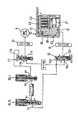
図2は、油圧回路の概略を示す図であり、前記2個のリニアソレノイドバルブSLS及びSLUを有すると共に、自動変速機構のプラネタリギヤユニットの伝達経路を切換えて、例えば前進4速又は5速、後進1速の変速段を達成する複数の摩擦係合要素(クラッチ及びブレーキ)を断接作動する複数の油圧サーボ9、10を有している。また、前記リニアソレノイドバルブSLS及びSLUの入力ポートa1,a2にはソレノイドモジュレータ圧が供給されており、これらリニアソレノイドバルブの出力ポートb1,b2からの制御油圧がそれぞれプレッシャコントロールバルブ11,12の制御油室11a,12aに供給されている。プレッシャコントロールバルブ11,12は、ライン圧がそれぞれ入力ポート11b,12bに供給されており、前記制御油圧にて調圧された出力ポート11c,12cからの調圧が、それぞれシフトバルブ13,15を介して適宜各油圧サーボ9,10に供給される。FIG. 2 is a diagram schematically showing a hydraulic circuit, which has the two linear solenoid valves SLS and SLU, and switches the transmission path of the planetary gear unit of the automatic transmission mechanism, for example, forward 4th speed or 5th speed, reverse speed A plurality of
なお、本油圧回路は、基本概念を示すためのものであって、各油圧サーボ9,10及びシフトバルブ13,15は、象徴的に示すものであり、実際には、自動変速機構に対応して油圧サーボは多数備えられており、これら油圧サーボへの油圧を切換えるシフトバルブも多数備えている。また、油圧サーボ10に示すように油圧サーボは、シリンダ16にオイルシール17により油密状に嵌合するピストン19を有しており、該ピストン19は、油圧室20に作用するプレッシャコントロールバルブ12からの調圧油圧に基づき、戻しスプリング21に抗して移動し、外側摩擦プレート22及び内側摩擦材23を接触する。該摩擦プレート及び摩擦材は、クラッチで示してあるが、ブレーキにも同様に対応することは勿論である。 This hydraulic circuit is for showing the basic concept, and the
ついで、図3及び図4に沿って、アップシフト変速時における係合側の制御(係合側油圧制御手段1a)について説明する。 Next, the engagement side control (engagement side hydraulic control means 1a) at the time of upshifting will be described with reference to FIGS.
まず、スロットル開度センサ3及び車速センサ6からの信号に基づき、制御部1がアップシフト信号を出力すると(START)、計時が開始される(S1)。そして、係合側の油圧サーボ用油圧指令値(係合側油圧)PAが所定PS1になるように所定信号をリニアソレノイドバルブSLU(又はSLS)に出力する(S2)。該所定圧PS1は、油圧サーボの油圧室20を満たすために必要な油圧に設定されており、所定時間tSA保持される。該所定時間tSAが経過すると(S3)、係合側油圧PAは、所定勾配[(PS1−PS2)/tSB]でスイープダウンし(S4)、係合側油圧PAが所定低圧PS2になると(S5)、該スイープダウンが停止され、該所定低圧PS2に保持される(S6)。該所定低圧PS2は、どのような状況にあっても、ピストンストローク圧以上でかつ入力軸の回転変化を生じさせない圧に設定されており、該所定低圧PS2は、計時tが所定時間tSE経過するまで保持される(S7)。上記S1〜S7がサーボ起動制御となる。First, when the
ついで、入力トルクTTに応じて変化する所定関数[PTA=fPTA(TT)]に基づき、入力回転数NTの回転変化が開始する直前(イナーシャ相の開始直前)の目標係合側油圧PTAを算定する(S8)。該イナーシャ相開始時直前の係合側油圧PTAは、まず入力トルクTTに対する係合側トルク分担トルクTA(=1/a・TT;a:トルク分担率)が算定され、更にPTA=(TA/AA)+BA+dPTA[BA;ピストンストローク圧(=スプリング荷重)、AA;摩擦板有効半径×ピストン面積×摩擦板枚数×摩擦係数、dPTA;油圧の遅れ分の油圧量]にて該目標油圧PTAが算出される。そして、該入力トルクTTに応じて算定されたイナーシャ相開始時直前の係合油圧PTAに基づき、予め設定された所定時間tTAにより所定勾配が算定され[(PTA−PS2)/tTA]、該勾配に基づき係合側油圧がスイープアップする(S9)。該比較的ゆるやかな勾配からなる第1のスイープアップにより、係合トルクが増加し、入力回転数変化が開始する直前の状態、即ち前記算出された所定目標係合油圧PTAまで油圧が上昇する(S10)。この状態は、アップシフト前の状態にあって、出力軸トルクが一時的に急降下するトルク相になる。上記S8〜S10がトルク相制御における第1のスイープ制御となる。Next, based on a predetermined function [PTA = fPTA (TT )] that changes according to the input torque TT , the target engagement immediately before the rotation change of the input rotation speedNT starts (immediately before the start of the inertia phase). The side hydraulic pressurePTA is calculated (S8). Engagement hydraulic pressureP TA immediately before the time of the inertia phase starts, first input torqueT T for engaging side torque allotment torqueT A (= 1 / a · T T; a: torque sharing rate) is calculated, further PTA = (TA / AA ) + BA + dPTA [BA ; piston stroke pressure (= spring load), AA ; friction plate effective radius × piston area × number of friction plates × friction coefficient, dPTA ; oil pressure delay The target hydraulic pressurePTA is calculated from the hydraulic amount of minutes]. Then, based on the engagement hydraulic pressurePTA immediately before the start of the inertia phase calculated according to the input torque TT , a predetermined gradient is calculated by a predetermined time tTA [(PTA −PS2 ) / tTA ], the engagement side hydraulic pressure sweeps up based on the gradient (S9). Due to the first sweep-up having the relatively gentle gradient, the engagement torque increases, and the hydraulic pressure rises to a state immediately before the input rotational speed change starts, that is, to the calculated predetermined target engagement hydraulic pressurePTA. (S10). This state is a state before the upshift, and becomes a torque phase in which the output shaft torque drops temporarily. The S8 to S10 are the first sweep control in the torque phase control.
なお、入力トルクTT(=タービントルク)は、車輌走行状況に基づき、マップによりスロットル開度とエンジン回転数に基づき線形補間してエンジントルクを求め、ついでトルクコンバータの入出力回転数から速度比を計算し、該速度比からマップによりトルク比を求め、そして前記エンジントルクに上記トルク比を乗じて求められる。The input torque TT (= turbine torque) is calculated based on the vehicle running condition by linearly interpolating the throttle opening and the engine speed based on the map, and then calculating the speed ratio from the input / output speed of the torque converter. Is calculated from the speed ratio by a map, and is obtained by multiplying the engine torque by the torque ratio.
そして、上記目標係合油圧PTAに達すると、即ち入力軸回転数NTの回転変化が開始されるイナーシャ相に入ったと予測される時点で、前記油圧の変化δPTAが入力軸回転数NTの回転変化開始時における目標とする目標回転変化率(dωa/dt;ωa′と表記)に応じた関数[δPTA=fδPTA(ωa′)]により算出される(S11)。即ち、kを定数、taimを目標変速開始時間、ωa′を目標回転変化率[ωa;目標回転数への勾配]、Iをイナーシャ量とすると、前記油圧変化δPTA=[I・ωa]/[k・taim]にて算定される。そして、該油圧変化δPTAによる勾配でスイープアップされる(S12)。該第2のスイープアップは、回転変化開始時の入力軸回転数NTSからの回転変化分ΔNが所定変速開始判定回転数dNSに達するまで続けられる(S13)。上記S11〜S13がトルク相制御における第2のスイープ制御となる。When reaching the target engagement pressure PTA, i.e. when the rotation change of the input shaft rotational speed NT is expected to have entered the inertia phase is started, the hydraulic change [delta] PTA is the input shaft rotational speed N target rotation change rate of the target in the rotation change start time ofT; is calculated by (dωa / dt ωa 'hereinafter) function in accordance with the[δP TA = fδP TA (ωa ')] (S11). That is, assuming that k is a constant, taim is a target shift start time, ωa ′ is a target rotational change rate [ωa; gradient to target rotational speed], and I is an inertia amount, the hydraulic pressure change δPTA = [I · ωa]. / [K · taim ]. Then, it is swept up with a gradient by the hydraulic pressure change δPTA (S12). Sweep-up of the second is continued until the rotation variation ΔN from the input shaft rotational speed NTS during rotation change start reaches a predetermined shift start judgment rotation speed dNS (S13). Said S11-S13 becomes the 2nd sweep control in torque phase control.
なお、上記目標変速開始時間taimは、入力軸回転数NTの関数として設定される。また、前記変速開始判定回転数dNSは、実際に回転数変化を検出し得る最小の回転数であり、入力軸回転数センサ5の検出精度に依存するものであって、低回転では回転検出精度が悪くなるため、検出回転数を大きくする必要があり、変速開始判定回転数dNSが大きくなるため、目標変速開始時間taimも長くなる。The target shift start time taim is set as a function of the input shaft rotational speedNT . Further, the shift start judgment rotation speed dNS is the minimum speed that can detect the rotational speed actually changes, be one that depends on the detection accuracy of the input shaft rotational speed sensor 5, rotation detection at low rotation since accuracy is poor, it is necessary to increase the detected rotation speed, since the shift start judgment rotation speed dNS becomes larger, the target shift start time taim is lengthened.
ついで、入力回転数の回転変化ΔNを検出してイナーシャ相開始を検出すると、係合側油圧変化δPIが、入力軸回転数センサ5の検出に基づく回転数の変化量ΔNにてフィードバック制御されて設定され、該δPIの勾配によりスイープアップされる(S14)。該δPIによるスイープアップは、変速完了までの回転変化量ΔNのα1[%]、例えば70[%]まで続けられる(S15)。即ち、NTSを変速開始時の入力軸回転数、ΔNを回転変化量、giを変速前ギヤ比、gi+1を変速後ギヤ比とすると、
[(ΔN×100)/NTS(gi−gi+1)]がα1[%]になるまで続けられる。
更に、上記回転変化量のα1[%]を越えると、滑らかな入力軸回転数変化量ΔNに基づくフィードバック制御により異なる油圧変化δPLが設定され、該δPLの勾配によりスイープアップされる(S16)。該δPLは、一般にδPIより僅かにゆるい勾配となり、該スイープアップは、変速完了近傍までの回転数変化量のα2[%]、例えば90[%]まで続けられる(S17)。上記δPI及びδPLによるスイープアップ目標変速時間tIは、油温による異なる複数のスロットル開度・車速マップが選択され、該マップに基づき設定される。上記S14〜S17がイナーシャ相制御となる。Then, upon detection of the inertia phase start detecting the rotational speed change ΔN of an input rotation speed, the engagement hydraulic pressure change [delta] PI is fed back controlled by the rotational speed variation ΔN based on the detection of the input shaft speed sensor 5 And is swept up by the gradient of δPI (S14). The sweep-up by δPI is continued up to α1 [%], for example, 70 [%] of the rotation change amount ΔN until the completion of the shift (S15). That is, the input shaft rotational speed of the shift start time and NTS, the rotational variation amount of .DELTA.N, pre-shift to gi gear ratio, when the g i+ 1 and after shifting gear ratio,
It continues until [(ΔN × 100) / NTS (gi −gi + 1 )] becomes α1 [%].
Further, when α1 [%] of the rotation change amount is exceeded, a different oil pressure change δPL is set by feedback control based on the smooth input shaft rotation speed change amount ΔN, and is swept up by the gradient of δPL ( S16). The δPL generally has a slightly gentler slope than δPI , and the sweep-up is continued up to α2 [%], for example, 90 [%] of the amount of change in the rotational speed until the shift is completed (S17). The [delta] PI and [delta] PL by sweep-up target shift time tI, a plurality of throttle opening, vehicle speed map that is different according to the oil temperature is selected and set based on the map. S14 to S17 are inertia phase control.
そして、該目標変速時間tIが経過すると、該計時時間tFが設定され(S18)、この状態はイナーシャ相が終了した状態と略々対応している。更に、比較的急な油圧変化δPFが設定されて、該油圧変化により油圧が急激にスイープアップし(S19)、そして前記計時時間tFから、係合圧まで上昇するに充分な時間に設定されている所定時間tFEが経過した状態で(S20)、係合側の油圧制御が完了する。上記S18〜S20が完了制御となる。When the target shift time tI elapses, is set the regimen at the time tF (S18), the state is in state and substantially corresponds to the inertia phase has ended. Furthermore, relatively suddenly hydraulic pressure change [delta] PF is set, setting the hydraulic pressure is rapidly swept up (S19), and from the measured time tF, the time sufficient to rise to engagement pressure by the hydraulic change When the predetermined timetFE has elapsed (S20), the hydraulic pressure control on the engagement side is completed. The above S18 to S20 are completion control.
ついで、図3及び図5に沿って、上述したアップシフト変速における解放側の制御(解放側油圧制御1b)について説明する。 Next, the release-side control (release-side
まず、制御部1からの変速指令により、係合側と同時に解放側油圧制御の計時が開始され(S21)、解放側油圧PBは、係合圧からなる高い油圧PWが供給されている(S22)。該高油圧PWの供給は、係合側油圧PAが第1のスイープアップを開始するまで(tSE)保持される(S23)。上記S21〜S23が待機制御Aであり、係合側制御のサーボ起動制御に対応している。First, in accordance with a shift command from the
そして、係合側油圧PA及び入力トルクTTの関数[TB’=fTB(PA,TT)]により解放側トルクTB’が算定され(S24)、更に余裕率S1U,S2Uが考慮されて(TB=S1U×TB’+S2U)、解放側トルクTBが算出される(S25)。そして、該解放側トルクTBから解放側油圧PBが算出される[PB=fPB(TB)](S26)。即ち、まず、係合側摩擦係合要素が分担するトルクTAが[TA=AA+PA+BA]にて算出され(AA;有効半径×ピストン=面積×枚数×摩擦係数、BB;ピストンストローク圧)、更にこれにより、解放側摩擦係合要素が分担するトルクTB’が、[TB’=(1/b)TT−(a/b)TA]にて算出される。なお、ここで、bは解放側のトルク分担、aは係合側のトルク分担、TTは入力軸トルクである。そして、余裕率(タイアップ度合)S1U,S2Uにより、係合側摩擦係合要素とのタイアップ度合を、ドライブフィーリングを考慮して設定し、解放側トルクTBが[TB=S1U×TB’+S2U]にて算出される。上記余裕率S1U,S2Uは、油温の相違により選択される多数のスロットル開度・車速マップにて、ドライバーのフィーリングに合うように任意に設定されるものであって、一般に、S1U>1.0、S2U>0.0からなる。更に、該余裕率を考慮した解放側トルクTBから、解放側油圧PBが、[PB=(TB/AB)+BB]にて算定される(AB;解放側摩擦係合要素の有効半径×ピストン面積×枚数×摩擦係数,BB;解放側ピストンストローク圧)。Then, the engagement hydraulic pressureP A and a function of the input torqueT T [T B '= f TB (P A, T T)] disengagement side torqueT B by' is calculated (S24), further marginS 1U, S2U is considered(T B = S 1U × T B '+ S 2U), the release-side torqueT B is calculated (S25). The disengagement side pressureP B is calculated from the disengagement side torqueT B [P B = f PB (T B)] (S26). That is, first, the torqueT A for the engagement side frictional engagement element is shared is calculated by[T A = A A + P A + B A] (A A; effective radius × piston = area × number × friction coefficient, BB; piston stroke pressure), further Thereby, 'is,[T B' torqueT B of the release side frictional engagement element to share - calculated by= (1 / b) T T (a / b) T A] Is done. Note that, b is the torque sharing the disengagement side, a is the torque sharing engagement side, the TT is the input shaft torque. The margin (tie-up degree) S1U, by S2U, a tie-up degree of the engagement side frictional engagement element, and set in consideration of the drive feeling, the disengagement side torque TB [TB = S1U × TB '+ S2U ]. The margin rates S1U and S2U are arbitrarily set to match the driver's feeling in a large number of throttle opening / vehicle speed maps selected depending on the difference in oil temperature.It consists of1U > 1.0 andS2U > 0.0. Further, the disengagement side torqueT B in consideration of the margin, the disengagement side pressureP B, [P B = ( T B / A B) + B B] is calculated by(A B; disengagement side frictional engagement Effective radius of element × Piston area × Number of sheets × Friction coefficient, BB ; Release piston stroke pressure).
図7に示す従来の油圧制御にあっては、解放側油圧PBによるスイープダウンは、係合側油圧PAに依存するものであるため、変速機の出力軸トルクが低下するトルク相にて屈曲する2段の勾配、即ち係合側の第1のスイープ制御に対応する比較的急勾配のスイープダウンと、係合側の第2のスイープ制御に対応する比較的緩勾配のスイープダウンからなるが、本発明にあっては、上記第2のスイープ制御に対応するスイープダウン部分が略々所定油圧を保持するように維持される。即ち、S26で算出された式による解放側油圧PBのスイープダウンは、係合側油圧PAの第1のスイープ制御に対応した勾配でスイープダウンし、該スイープダウンは、解放側油圧PBが、[PB≦fPB(0)+PKEEP+PLS2T]になるまで続く(S27)。上記S24〜S27が初期制御Bであり、係合側制御の第1のスイープ制御に対応している。In the conventional hydraulic control shown in FIG. 7, the sweep-down by the release-side hydraulic pressure PB, since is dependent on the engagement hydraulic pressure PA, in the torque phase output shaft torque of the transmission is reduced 2 steps of bending, that is, a relatively steep sweep down corresponding to the first sweep control on the engagement side and a sweep down of a relatively gentle slope corresponding to the second sweep control on the engagement side. However, in the present invention, the sweep-down portion corresponding to the second sweep control is maintained so as to maintain a predetermined hydraulic pressure. That is, sweep-down on the release side hydraulic pressure PB by the formula calculated in S26 is swept down with a gradient corresponding to the first sweep control the engagement hydraulic pressure PA, the sweep-down is release-side hydraulic pressure PB Continues until [PB ≦ fPB (0) + PKEEP + PLS2T ] (S27). S24 to S27 are the initial control B, which corresponds to the first sweep control of the engagement side control.
該解放側油圧PBは、解放側の分担トルク(TB)が微小トルクに相当する油圧[fPB(0)]と、マップにより選択される目標保持圧補正項[PKEEP]と、例えば特開平11−63202号公報で示される学習制御により設定される油圧[PLS2T]との和からなり、解放側(第2の)摩擦係合要素が微小トルク容量を保持する値からなる。なお、図3(a)では、上記油圧[fPB(0)+PKEEP+PLS2T]が、係合側油圧PAの目標係合側油圧PTAに相当する解放側油圧に設定され、従って係合側油圧が目標油圧PTAとなる時間tTAと一致しているが、必ずしも一致させなくてもよい。The release side hydraulic pressure PB includes a hydraulic pressure [fPB (0)] in which the release side shared torque (TB ) corresponds to a minute torque, a target holding pressure correction term [PKEEP ] selected by the map, Itconsists of the sum of the hydraulic pressure [PLS2T ] set by the learning control shown in Japanese Patent Laid-Open No.11-63202, and the release side (second) friction engagement element has a value that maintains a minute torque capacity. In FIG. 3 (a), the hydraulic[fP B (0) + P KEEP + P LS2T] is set to the release side hydraulic pressure corresponding to the target engagement side hydraulic pressureP TA of the engagement side hydraulic pressureP A, thus engaging Although the coincidence hydraulic pressure coincides with the time tTA at which the target hydraulic pressurePTA is reached, it does not necessarily have to coincide.
上記[PLS2T]は、学習制御により、次回の変速時に補正される値であって、入力回転数NTの加速度(回転変化率・角加速度)と入力回転数NTの変化開始までの時間(タイムラグ)により、適宜、補正される値である。例えば、以下のように判定される。
・エンジン吹きが発生し、該エンジン吹きまでの時間が長くなく、入力回転数NTの変化開始が遅くないときには、解放側油圧が低すぎと判断し、次回の変速時に[PLS2T]を増加させる。
・エンジントルクが低く、入力回転数NTの変化開始が遅く、入力回転数NTの変化開始時の加速度が大きいときには、解放側油圧が高すぎと判断し、次回の変速時に[PLS2T]を減少させる。[PLS2T ] is a value that is corrected at the next shift by learning control, and is the time until the input rotation speedNT acceleration (rotational change rate / angular acceleration) and the input rotation speedNT start to change. (Time lag) is a value corrected as appropriate. For example, it is determined as follows.
・ When engine blow occurs, the time until the engine blow is not long, and the start of change of the input rotational speedNT is not slow, it is determined that the release side hydraulic pressure is too low, and [PLS2T ] is increased at the next shift. Let
When the engine torque is low, the input rotation speedNT starts to change slowly, and the acceleration at the start of the change of the input rotation speedNT is large, it is determined that the release side hydraulic pressure is too high, and [PLS2T ] at the next shift Decrease.
上記目標保持圧補正項PKEEPは、図3(b)に示すように、マップにより選択され、各変速段において選択される多数の入力トルクにて、解放側摩擦係合要素が微小トルク容量を保持でき、なおかつドライバーのフィーリングに合うように任意に設定される。低トルク領域では、入力されるトルクも比較的低いため、上記係合側油圧に依存する解放側油圧PBは、比較的低い値を出力すればよく、従って上記保持圧補正項PKEEPは若干の負の値又は0と設定され、タイアップによる回転変化開始までの間延びを防止する。中トルク領域では、上記解放側油圧PBは、比較的高く出力されており、解放側係合要素の微小トルク容量に対する余裕率が低トルク時に比較して若干あるため、上記保持圧補正項PKEEPは0近傍の値に設定される。The target holding pressure correction term PKEEP is selected by a map as shown in FIG. 3B, and the release side frictional engagement element has a small torque capacity at a large number of input torques selected at each gear. It can be held, and it is arbitrarily set to match the feeling of the driver. Since the input torque is relatively low in the low torque region, the disengagement side hydraulic pressure PB depending on the engagement side hydraulic pressure only needs to be output at a relatively low value, and therefore the holding pressure correction term PKEEP is slightly Is set to a negative value of 0 or 0, and the extension until the start of the rotation change due to the tie-up is prevented. In the middle torque region, the release side hydraulic pressure PB is output at a relatively high value, and there is a margin ratio with respect to the minute torque capacity of the release side engagement element slightly compared to when the torque is low, so the holding pressure correction term PKEEP is set to a value near zero.
高トルク領域では以下の2つの考え方があり、いずれか一方が選択される。1つは、高トルク領域では回転変化開始までの間延びによる係合側摩擦係合要素への熱的負荷を考慮して、なるべく解放側油圧PBを保持させないようにする考え方であり、これによると、上記保持圧補正項PKEEPは、負の値が設定される。2つ目の考え方は、係合側摩擦係合要素が熱的負荷に対して充分に余裕がある場合であり、高トルク領域でも解放側油圧PBを保持させるため、上記保持圧補正項PKEEPは、0近傍の値に設定され、これにより解放側で微小トルク容量を保持させてイナーシャショックの緩和を図る。There are the following two ways of thinking in the high torque region, and either one is selected. One is an idea to prevent the disengagement side hydraulic pressure PB from being held as much as possible in consideration of the thermal load on the engagement side frictional engagement element due to the extension until the start of the rotation change in the high torque region. The holding pressure correction term PKEEP is set to a negative value. The second idea is that the engagement-side frictional engagement element has a sufficient margin for the thermal load. In order to maintain the release-side hydraulic pressure PB even in the high torque region, the holding pressure correction term PKEEP is set to a value in the vicinity of 0, thereby holding a small torque capacity on the release side to alleviate the inertia shock.
解放側油圧PBがS27で設定された油圧より低くなると、予め設定された勾配δPBにてスイープダウンする(S28)。該勾配δPBは、0を含む値であり、極めて小さな値に設定されており、実質的に上記S27で設定された解放側油圧PBが、入力回転数NTの回転変化が実質的に開始(イナーシャ相開始;ΔN≧dNS)まで保持される。上記勾配δPBは0でもよいが、解放側油圧のバラツキを考慮すると、該バラツキによる回転変化開始までの間延びを防止するため、極めて緩いスイープダウンに設定する方が実用上望ましい。上記S27で設定された解放側油圧PBが、微小トルク容量に設定されており、該油圧を極めて緩い勾配δPBにてスイープダウンすることにより、若干のタイアップぎみとしてエンジン吹きを防止しつつ、回転変化開始までの間延びを防止できる。上記S28,S29が保持制御Bであり、係合側制御の第2のスイープ制御に対応する。上記S24〜S29(初期制御B+保持制御C)が係合側制御のトルク相制御に対応する。When the disengagement side hydraulic pressure PB becomes lower than the hydraulic pressure set in S27, it sweeps down at a preset gradient δPB (S28). The gradient [delta] PB is a value including zero, is set to an extremely smallSana value, substantially disengagement side pressure PB that is set at S27 is, rotation change of the input rotational speed NT is substantially Until the start (inertia phase start; ΔN ≧ dNS ). The gradient δPB may be 0. However, in consideration of variation in the release side hydraulic pressure, it is practically desirable to set a very gentle sweep down in order to prevent extension until the start of rotation change due to the variation. Disengagement side pressure PB that is set at S27 is, is set to the minute torque capacity, by sweeping down the hydraulic by very gentle gradient [delta] PB, while preventing engine racing as some tie-up Gimi It is possible to prevent the extension until the start of the rotation change. S28 and S29 are holding control B, which corresponds to the second sweep control of the engagement side control. S24 to S29 (initial control B + holding control C) correspond to the torque phase control of the engagement side control.
そして、該極めて緩やかなスイープダウンは、係合側と同様に、入力軸回転変化量ΔNが、所定回転変化開始判定回転数dNSになる(イナーシャ相開始の検出)まで続く(S29)。ついで、解放油圧の変化δPEが設定され、該油圧変化による勾配でスイープダウンし(S30)、該スイープダウンは、解放側油圧PBが0になるまで続き(S31)、これにより、解放側の油圧制御が完了する。上記S30,S31が終期制御Dであり、後述する緩勾配スイープダウン制御と急勾配スイープダウン制御を有する。Then, the very gentle sweep down, like the engaging side, the input shaft rotational speed change amount .DELTA.N, continues until a predetermined rotation change start determining rotational speed dNS (detection of inertia phase start) (S29). Next, a change δPE of the release hydraulic pressure is set, and sweeps down with a gradient due to the change in the hydraulic pressure (S30), and the sweep down continues until the release side hydraulic pressure PB becomes 0 (S31). The hydraulic control is completed. The S30 and S31 are the final control D, and have a slow gradient sweep down control and a steep gradient sweep down control which will be described later.
上記S30の勾配δPEは、2種類が選択される。急勾配δPE1は、図7に示す従来のものと同じであり、タイアップを防止した速やかな変速が行われ、本実施の形態であっては、手動変速モード時に選択される。緩勾配δPE2は、上記従来のものより緩やかな勾配であって、係合側油圧制御のS17、即ちイナーシャ相制御が終了する(完了制御の前まで)までに解放側油圧PBが0(S31)になるように設定される。Two types of gradient δPE in S30 are selected. The steep slope δPE1 is the same as that of the prior art shown in FIG. 7, and a quick shift that prevents tie-up is performed. In the present embodiment, the steep gradient δPE1 is selected in the manual shift mode. The gentle gradient δPE2 is gentler than the conventional one, and the release side hydraulic pressure PB is 0 (until the completion of the inertia phase control (before completion control) in S17 of the engagement side hydraulic control, that is, before completion control). S31).
本実施の形態の自動変速機は、自動変速モードの外に、手動により変速段を選択できる手動変速モードを備えており、通常は、緩勾配δPE2に設定されているが、手動変速モードが選択されていることを検出する手動変速モード検出手段8(図1参照)からの信号に基づき上記急勾配δPE1が設定される。これにより、自動変速モード時にあっては、快適で滑らかな(コンフォータブル)シフトフィーリングが得られ、手動変速モード時にあっては、スポーティなシフトフィーリングが得られる。The automatic transmission according to the present embodiment has a manual shift mode in which the gear position can be manually selected in addition to the automatic shift mode, and is normally set to a gentle gradient δPE2 , but the manual shift mode is The steep slope δPE1 is set on the basis of a signal from the manual shift mode detecting means 8 (see FIG. 1) for detecting the selection. As a result, a comfortable and smooth (comfortable) shift feeling is obtained in the automatic transmission mode, and a sporty shift feeling is obtained in the manual transmission mode.
通常時(自動変速モード時)は、緩勾配δPE2が選択されており、図6に示すように、S27,S29の微小トルク容量保持圧と相俟って、出力軸トルクTOの急変化(図8参照)をなくして、イナーシャショックの発生を防止できる。なお、S30での緩勾配δPE2の採用により、タイアップ状態が発生すると考えられるが、S27において、解放側油圧PB(=fPB(0)+PKEEP+PLS2T)が微小トルク保持容量を保持できる油圧レベルに設定され、かつS29で極めて緩いスイープダウンとなっており、回転変化開始時には、解放側油圧は微小トルク容量を保持可能な所定の油レベル以下となっているため、過度のタイアップを発生することはない。Normal (automatic shift mode), and low-gradient [delta] PE2 are selected, as shown in FIG. 6, S27, I S29 minute torque capacity holding pressure coupled with the, abrupt change of the output shaft torque TO (See FIG. 8) can be eliminated, and the occurrence of inertia shock can be prevented. Although it is considered that a tie-up state occurs due to the adoption of the gentle gradient δPE2 in S30, in S27, the release side hydraulic pressure PB (= fPB (0) + PKEEP + PLS2T ) holds a minute torque holding capacity. It is set to a hydraulic level that can be used, and it is a very gentle sweepdown in S29. At the start of rotation change, the release side hydraulic pressure is below a predetermined oil level that can hold a minute torque capacity, soexcessive tie-up Will not occur.
1 制御部
1a 係合側油圧制御手段
1b 解放側油圧制御手段
2〜8 各センサ
9,10 油圧サーボ
SLS,SLU 油圧操作手段(リニアソレノイドバルブ)
PA 係合側油圧
PB 解放側油圧
B 初期制御
C 保持制御
δPB 極めて緩い勾配
D 終期制御
D1 緩勾配スイープダウン制御
D2 急勾配スイープダウン制御
δPE1 急勾配
δPE2 緩勾配
PTA 目標油圧
PKEEP (目標保持油圧)補正項
DESCRIPTION OF
PA engagement side hydraulic pressure PB release side hydraulic pressure B initial control C holding control δPB extremely gentle gradient D final control D1 gentle gradient sweep down control D2 steep gradient sweep down control δPE1 steep gradient δPE2 gentle gradient PTA target Oil pressure PKEEP (target holding oil pressure) correction term
Claims (8)
Translated fromJapanese少なくとも前記第1及び第2の摩擦係合要素用油圧サーボの油圧を制御する油圧操作手段と、車輌走行状況に基づく各センサからの信号を入力して、前記油圧操作手段へ油圧制御信号を出力する制御部と、を備えてなる自動変速機の油圧制御装置において、
前記制御部は、前記第1の摩擦係合要素用油圧サーボへの油圧変化を算出して前記油圧操作手段に出力する係合側油圧制御手段と、前記第2の摩擦係合要素用油圧サーボへの油圧を算出して前記油圧操作手段に出力する解放側油圧制御手段と、を有し、
前記解放側油圧制御手段は、トルク相において、前記係合側油圧制御手段による係合側油圧に依存して算出され、前記第2の摩擦係合要素が微小トルク容量を有する所定解放側油圧までスイープダウンする初期制御と、該初期制御後、前記トルク相に続くイナーシャ相の開始を検出するまで、実質的に前記所定解放側油圧を保持するように制御する保持制御と、を備え、
前記所定解放側油圧は、前記第2の摩擦係合要素の分担トルクが微小トルクに相当する油圧と、マップにより選択される目標保持圧補正項と、学習制御により設定される油圧との和からなる、
ことを特徴とする自動変速機の油圧制御装置。A plurality of frictional engagement elements that change the power transmission path between the input shaft and the output shaft, and a hydraulic servo that operates to disconnect and engage these frictional engagement elements. And engaging the first frictional engagement element and releasing the second frictional engagement element to achieve an upshift to a predetermined gear stage,
Input hydraulic control means for controlling the hydraulic pressure of at least the first and second friction engagement element hydraulic servos, and signals from each sensor based on the vehicle running condition, and output hydraulic control signals to the hydraulic operation means A hydraulic control device for an automatic transmission comprising:
The control unit calculates an oil pressure change to the first friction engagement element hydraulic servo and outputs the change to the hydraulic operation means; and the second friction engagement element hydraulic servo. A release-side hydraulic control means for calculating the hydraulic pressure to output to the hydraulic operation means,
The release side hydraulic pressure control means is calculated depending on the engagement side hydraulic pressure by the engagement side hydraulic pressure control means in the torque phase, and the second friction engagement element has a predetermined release side hydraulic pressure having a minute torque capacity. an initial control sweeping down, after initial control until it detects the start of the inertia phase following the torque phase,e Bei and a holding control for controlling so as to hold substantially said predetermineddisengagement hydraulicpressure,
The predetermined release side hydraulic pressure is a sum of a hydraulic pressure corresponding to a minute torque shared by the second friction engagement element, a target holding pressure correction term selected by a map, and a hydraulic pressure set by learning control. Become,
A hydraulic control device for an automatic transmission.
請求項1記載の自動変速機の油圧制御装置。The hydraulic pressure set by the learning control is a value that is corrected by the acceleration of the input rotation speed and the time until the change start of the input rotation speed.
The hydraulic control device for an automatic transmission according to claim 1.
請求項1又は2記載の自動変速機の油圧制御装置。The target holding pressure correction term is set according to an input torque selected at each gear stage.
The hydraulic control device for an automatic transmission according to claim 1 or 2.
請求項1ないし3のいずれか記載の自動変速機の油圧制御装置。The holding control is swept down with a very gentle slope,
The hydraulic control device for an automatic transmission according toany one of claims1 to 3 .
請求項1ないし4のいずれか記載の自動変速機の油圧制御装置。The release-side hydraulic control means performs a gentle gradient that sweeps down at a gentle gradient so that the release-side hydraulic pressure becomes zero after the holding control and until the inertia phase control of the engagement-side hydraulic control means ends. With sweep down control,
The hydraulic control device for an automatic transmission according to any one of claims 1 to4 .
前記緩勾配スイープダウン制御と前記急勾配スイープダウン制御のいずれか一方を選択してなる、
請求項1ないし5のいずれか記載の自動変速機の油圧制御装置。The release-side hydraulic control means has a steep slope sweepdown control that sweeps down at a steeper slope than the gentle slope of the gentle slope sweepdown control after the holding control,
One of the gentle slope sweep down control and the steep slope sweep down control is selected.
The hydraulic control device for an automatic transmission according to any one of claims 1 to5 .
前記自動変速モードにあっては前記緩勾配スイープダウン制御が選択され、
前記手動変速モードにあっては前記急勾配スイープダウン制御が選択されてなる、
請求項6記載の自動変速機の油圧制御装置。The automatic transmission includes an automatic transmission mode and a manual transmission mode,
In the automatic transmission mode, the gentle gradient sweep down control is selected,
In the manual shift mode, the steep slope sweep down control is selected.
The hydraulic control device for an automatic transmission according to claim6 .
前記解放側油圧制御手段の前記初期制御が、前記第1のスイープ制御の係合側油圧に依存して算出されてなる、
請求項1ないし7のいずれか記載の自動変速機の油圧制御装置。The engagement-side hydraulic control means detects a first sweep control that sweeps up to a target hydraulic pressure in a state immediately before the inertia phase starts with a first gradient, and a rotational change of the input rotational speed from the target hydraulic pressure. And a second sweep control that sweeps up with a second slope that is gentler than the first slope,
The initial control of the release side hydraulic control means is calculated depending on the engagement side hydraulic pressure of the first sweep control.
The hydraulic control device for an automatic transmission according to any one of claims 1 to7 .
Priority Applications (5)
| Application Number | Priority Date | Filing Date | Title |
|---|---|---|---|
| JP2006099837AJP4821409B2 (en) | 2006-03-31 | 2006-03-31 | Hydraulic control device for automatic transmission |
| DE112007000032.5TDE112007000032B4 (en) | 2006-03-31 | 2007-03-28 | Hydraulic control unit for automatic transmission |
| PCT/JP2007/056559WO2007119549A1 (en) | 2006-03-31 | 2007-03-28 | Hydraulic controller of automatic transmission |
| CN200780000857.1ACN101341356B (en) | 2006-03-31 | 2007-03-28 | Oil pressure control device for automatic transmission |
| US11/693,342US7841455B2 (en) | 2006-03-31 | 2007-03-29 | Hydraulic control system for automatic transmission |
Applications Claiming Priority (1)
| Application Number | Priority Date | Filing Date | Title |
|---|---|---|---|
| JP2006099837AJP4821409B2 (en) | 2006-03-31 | 2006-03-31 | Hydraulic control device for automatic transmission |
Publications (2)
| Publication Number | Publication Date |
|---|---|
| JP2007271035A JP2007271035A (en) | 2007-10-18 |
| JP4821409B2true JP4821409B2 (en) | 2011-11-24 |
Family
ID=38609324
Family Applications (1)
| Application Number | Title | Priority Date | Filing Date |
|---|---|---|---|
| JP2006099837AExpired - Fee RelatedJP4821409B2 (en) | 2006-03-31 | 2006-03-31 | Hydraulic control device for automatic transmission |
Country Status (5)
| Country | Link |
|---|---|
| US (1) | US7841455B2 (en) |
| JP (1) | JP4821409B2 (en) |
| CN (1) | CN101341356B (en) |
| DE (1) | DE112007000032B4 (en) |
| WO (1) | WO2007119549A1 (en) |
Families Citing this family (30)
| Publication number | Priority date | Publication date | Assignee | Title |
|---|---|---|---|---|
| RU2326171C2 (en)* | 2000-01-28 | 2008-06-10 | Мартек Биосайенсис Корпорейшн | Method for producing lipides containing polyunsaturated fatty acids (variants) and method for cultivating microorganisms producing said lipids |
| US8303463B2 (en)* | 2007-10-26 | 2012-11-06 | GM Global Technology Operations LLC | Method and apparatus to control clutch fill pressure in an electro-mechanical transmission |
| JP4883533B2 (en)* | 2008-03-06 | 2012-02-22 | ジヤトコ株式会社 | Shift control device for automatic transmission |
| JP4914467B2 (en)* | 2009-07-17 | 2012-04-11 | ジヤトコ株式会社 | Continuously variable transmission and control method thereof |
| JP4799647B2 (en)* | 2009-07-17 | 2011-10-26 | 日産自動車株式会社 | Control device for continuously variable transmission for vehicle |
| JP4875732B2 (en)* | 2009-07-17 | 2012-02-15 | 日産自動車株式会社 | Continuously variable transmission |
| JP5256253B2 (en)* | 2009-07-17 | 2013-08-07 | 日産自動車株式会社 | Automatic transmission |
| JP4790834B2 (en)* | 2009-07-17 | 2011-10-12 | 日産自動車株式会社 | Control device for continuously variable transmission for vehicle |
| JP4991798B2 (en)* | 2009-07-17 | 2012-08-01 | 日産自動車株式会社 | Continuously variable transmission |
| JP5205412B2 (en)* | 2009-07-17 | 2013-06-05 | ジヤトコ株式会社 | Continuously variable transmission and control method thereof |
| JP4852130B2 (en)* | 2009-07-17 | 2012-01-11 | 日産自動車株式会社 | Control device for continuously variable transmission for vehicle |
| JP5207080B2 (en)* | 2009-10-30 | 2013-06-12 | アイシン・エィ・ダブリュ株式会社 | Vehicle control device |
| JP5031052B2 (en)* | 2010-03-16 | 2012-09-19 | ジヤトコ株式会社 | Control device for automatic transmission |
| JP5218860B2 (en)* | 2010-04-02 | 2013-06-26 | アイシン・エィ・ダブリュ株式会社 | Control device |
| JP5434889B2 (en)* | 2010-11-10 | 2014-03-05 | アイシン・エィ・ダブリュ株式会社 | Transmission and control method thereof |
| US8762014B2 (en) | 2011-09-30 | 2014-06-24 | Caterpillar Inc. | Variator characterization for feed forward torque control |
| JP5899902B2 (en)* | 2011-12-22 | 2016-04-06 | 日産自動車株式会社 | Shift control device for friction transmission |
| DE112012006344B8 (en)* | 2012-05-08 | 2019-08-08 | Toyota Jidosha Kabushiki Kaisha | Speed change control system for vehicles |
| KR101405198B1 (en)* | 2012-12-07 | 2014-06-27 | 기아자동차 주식회사 | Method and system for controlling anti jerk of hybrid electric vehicle |
| JP2017067281A (en)* | 2015-10-02 | 2017-04-06 | トヨタ自動車株式会社 | Gear change control device of vehicle |
| JP6288048B2 (en)* | 2015-11-19 | 2018-03-07 | トヨタ自動車株式会社 | Shift control device for automatic transmission |
| JP6845043B2 (en)* | 2017-03-02 | 2021-03-17 | トヨタ自動車株式会社 | Vehicle shift control device |
| US10344851B2 (en)* | 2017-06-27 | 2019-07-09 | Ford Global Technologies, Llc | Method of controlling a transmission during an upshift |
| JP6766966B2 (en)* | 2017-07-18 | 2020-10-14 | アイシン・エィ・ダブリュ株式会社 | Control device |
| KR102322569B1 (en)* | 2017-09-25 | 2021-11-04 | 현대자동차주식회사 | Shift control method for hybrid electric vehicle |
| JP2020063815A (en)* | 2018-10-18 | 2020-04-23 | トヨタ自動車株式会社 | Control device for vehicular power transmission device |
| US11221068B2 (en)* | 2018-11-30 | 2022-01-11 | International Engine Intellectual Property Company, Llc | Transmission grade sensor rationality and trim algorithm |
| CN111536229B (en)* | 2020-05-08 | 2022-06-28 | 南京劲力变速器科技有限公司 | Gear-up control method for AT automatic transmission |
| CN112648364B (en)* | 2020-12-31 | 2022-06-10 | 潍柴动力股份有限公司 | Clutch control method and device |
| US11414081B1 (en)* | 2021-02-04 | 2022-08-16 | Ford Global Technologies, Llc | Predictive-based control for transmission shifting |
Family Cites Families (11)
| Publication number | Priority date | Publication date | Assignee | Title |
|---|---|---|---|---|
| JPH04244663A (en)* | 1991-01-25 | 1992-09-01 | Nissan Motor Co Ltd | Shift controller for automatic transmission |
| JP3131302B2 (en)* | 1992-08-31 | 2001-01-31 | マツダ株式会社 | Transmission control device for automatic transmission |
| JP3377349B2 (en)* | 1995-11-29 | 2003-02-17 | ジヤトコ株式会社 | Downshift control device for automatic transmission |
| JP3331844B2 (en)* | 1995-12-19 | 2002-10-07 | アイシン・エィ・ダブリュ株式会社 | Hydraulic control device for automatic transmission |
| JP3385523B2 (en)* | 1997-08-13 | 2003-03-10 | アイシン・エィ・ダブリュ株式会社 | Hydraulic control device for automatic transmission |
| JP3339405B2 (en)* | 1997-09-04 | 2002-10-28 | アイシン・エィ・ダブリュ株式会社 | Hydraulic control device for automatic transmission |
| JP4066513B2 (en)* | 1998-05-25 | 2008-03-26 | 株式会社デンソー | Control device for automatic transmission and recording medium |
| JP2000266173A (en)* | 1999-03-18 | 2000-09-26 | Jatco Transtechnology Ltd | Speed change control device for automatic transmission |
| JP3528710B2 (en)* | 1999-10-25 | 2004-05-24 | アイシン・エィ・ダブリュ株式会社 | Hydraulic control device for automatic transmission |
| JP2002295663A (en)* | 2001-03-30 | 2002-10-09 | Aisin Aw Co Ltd | Gear shift control device of automatic transmission |
| US6931315B2 (en)* | 2002-12-02 | 2005-08-16 | Toyota Jidosha Kabushiki Kaisha | Shift control apparatus and shift control method for a vehicular automatic transmission |
- 2006
- 2006-03-31JPJP2006099837Apatent/JP4821409B2/ennot_activeExpired - Fee Related
- 2007
- 2007-03-28CNCN200780000857.1Apatent/CN101341356B/ennot_activeExpired - Fee Related
- 2007-03-28DEDE112007000032.5Tpatent/DE112007000032B4/ennot_activeExpired - Fee Related
- 2007-03-28WOPCT/JP2007/056559patent/WO2007119549A1/enactiveApplication Filing
- 2007-03-29USUS11/693,342patent/US7841455B2/enactiveActive
Also Published As
| Publication number | Publication date |
|---|---|
| WO2007119549A1 (en) | 2007-10-25 |
| DE112007000032T5 (en) | 2008-08-14 |
| CN101341356B (en) | 2013-06-26 |
| DE112007000032B4 (en) | 2017-11-09 |
| JP2007271035A (en) | 2007-10-18 |
| US20080032861A1 (en) | 2008-02-07 |
| US7841455B2 (en) | 2010-11-30 |
| CN101341356A (en) | 2009-01-07 |
Similar Documents
| Publication | Publication Date | Title |
|---|---|---|
| JP4821409B2 (en) | Hydraulic control device for automatic transmission | |
| JP3331844B2 (en) | Hydraulic control device for automatic transmission | |
| EP0900957B1 (en) | Hydraulic control system for automatic transmission | |
| US5954776A (en) | Hydraulic control apparatus of automatic transmission | |
| JP3385523B2 (en) | Hydraulic control device for automatic transmission | |
| US6503165B1 (en) | Hydraulic control device for automatic transmission | |
| JP3427671B2 (en) | Transmission control device for automatic transmission | |
| EP1431624B1 (en) | Shift control device for automatic transmission | |
| KR20110104440A (en) | Control device of automatic transmission | |
| JP3528712B2 (en) | Automotive gear change control device | |
| JP3679242B2 (en) | Hydraulic control device for automatic transmission | |
| JP3903705B2 (en) | Automobile speed change control device | |
| JP3399313B2 (en) | Hydraulic control device for automatic transmission | |
| JP3528537B2 (en) | Hydraulic control device for automatic transmission | |
| JPH1182704A (en) | Hydraulic control device of automatic transmission | |
| JP3371747B2 (en) | Transmission control device for automatic transmission | |
| JP3536664B2 (en) | Hydraulic control device for automatic transmission | |
| JPH10181386A (en) | Shift control device automatic transmission | |
| JP3339430B2 (en) | Hydraulic control device for automatic transmission | |
| JP3975665B2 (en) | Automobile speed change control device | |
| JPH07269691A (en) | Shift control device for automatic transmission | |
| JPH10250415A (en) | Speed change control device for automatic transmission | |
| JPH11108167A (en) | Hydraulic control device for automatic transmission |
Legal Events
| Date | Code | Title | Description |
|---|---|---|---|
| A621 | Written request for application examination | Free format text:JAPANESE INTERMEDIATE CODE: A621 Effective date:20080130 | |
| A131 | Notification of reasons for refusal | Free format text:JAPANESE INTERMEDIATE CODE: A131 Effective date:20101207 | |
| A521 | Request for written amendment filed | Free format text:JAPANESE INTERMEDIATE CODE: A523 Effective date:20110204 | |
| TRDD | Decision of grant or rejection written | ||
| A01 | Written decision to grant a patent or to grant a registration (utility model) | Free format text:JAPANESE INTERMEDIATE CODE: A01 Effective date:20110809 | |
| A01 | Written decision to grant a patent or to grant a registration (utility model) | Free format text:JAPANESE INTERMEDIATE CODE: A01 | |
| A61 | First payment of annual fees (during grant procedure) | Free format text:JAPANESE INTERMEDIATE CODE: A61 Effective date:20110822 | |
| R150 | Certificate of patent or registration of utility model | Ref document number:4821409 Country of ref document:JP Free format text:JAPANESE INTERMEDIATE CODE: R150 Free format text:JAPANESE INTERMEDIATE CODE: R150 | |
| FPAY | Renewal fee payment (event date is renewal date of database) | Free format text:PAYMENT UNTIL: 20140916 Year of fee payment:3 | |
| LAPS | Cancellation because of no payment of annual fees |