JP4820447B2 - Multicast transmission system and method - Google Patents
Multicast transmission system and methodDownload PDFInfo
- Publication number
- JP4820447B2 JP4820447B2JP2009553613AJP2009553613AJP4820447B2JP 4820447 B2JP4820447 B2JP 4820447B2JP 2009553613 AJP2009553613 AJP 2009553613AJP 2009553613 AJP2009553613 AJP 2009553613AJP 4820447 B2JP4820447 B2JP 4820447B2
- Authority
- JP
- Japan
- Prior art keywords
- vxn
- nodes
- multicast
- topology
- virtual
- Prior art date
- Legal status (The legal status is an assumption and is not a legal conclusion. Google has not performed a legal analysis and makes no representation as to the accuracy of the status listed.)
- Expired - Fee Related
Links
- 230000005540biological transmissionEffects0.000titleclaimsdescription32
- 238000000034methodMethods0.000titleclaimsdescription14
- 230000011664signalingEffects0.000claimsdescription7
- 230000000644propagated effectEffects0.000claimsdescription6
- 230000008859changeEffects0.000claimsdescription4
- 230000004044responseEffects0.000claimsdescription4
- 230000008034disappearanceEffects0.000claims1
- 238000010586diagramMethods0.000description10
- 238000004891communicationMethods0.000description6
- 230000007704transitionEffects0.000description6
- 238000007726management methodMethods0.000description5
- 238000012546transferMethods0.000description5
- 230000006399behaviorEffects0.000description4
- 238000004458analytical methodMethods0.000description3
- 238000004364calculation methodMethods0.000description3
- 238000012545processingMethods0.000description3
- 238000012360testing methodMethods0.000description3
- 238000007728cost analysisMethods0.000description2
- 230000003111delayed effectEffects0.000description2
- 238000009826distributionMethods0.000description2
- 238000012986modificationMethods0.000description2
- 230000004048modificationEffects0.000description2
- 238000011084recoveryMethods0.000description2
- 238000013517stratificationMethods0.000description2
- 230000009977dual effectEffects0.000description1
- 230000003993interactionEffects0.000description1
- 238000005457optimizationMethods0.000description1
- 238000002360preparation methodMethods0.000description1
- 230000008569processEffects0.000description1
- 238000003860storageMethods0.000description1
Images


Classifications
- H—ELECTRICITY
- H04—ELECTRIC COMMUNICATION TECHNIQUE
- H04L—TRANSMISSION OF DIGITAL INFORMATION, e.g. TELEGRAPHIC COMMUNICATION
- H04L12/00—Data switching networks
- H04L12/02—Details
- H04L12/16—Arrangements for providing special services to substations
- H04L12/18—Arrangements for providing special services to substations for broadcast or conference, e.g. multicast
- H—ELECTRICITY
- H04—ELECTRIC COMMUNICATION TECHNIQUE
- H04L—TRANSMISSION OF DIGITAL INFORMATION, e.g. TELEGRAPHIC COMMUNICATION
- H04L45/00—Routing or path finding of packets in data switching networks
- H04L45/02—Topology update or discovery
- H—ELECTRICITY
- H04—ELECTRIC COMMUNICATION TECHNIQUE
- H04L—TRANSMISSION OF DIGITAL INFORMATION, e.g. TELEGRAPHIC COMMUNICATION
- H04L45/00—Routing or path finding of packets in data switching networks
- H04L45/12—Shortest path evaluation
- H04L45/122—Shortest path evaluation by minimising distances, e.g. by selecting a route with minimum of number of hops
- H—ELECTRICITY
- H04—ELECTRIC COMMUNICATION TECHNIQUE
- H04L—TRANSMISSION OF DIGITAL INFORMATION, e.g. TELEGRAPHIC COMMUNICATION
- H04L45/00—Routing or path finding of packets in data switching networks
- H04L45/16—Multipoint routing
- H—ELECTRICITY
- H04—ELECTRIC COMMUNICATION TECHNIQUE
- H04L—TRANSMISSION OF DIGITAL INFORMATION, e.g. TELEGRAPHIC COMMUNICATION
- H04L45/00—Routing or path finding of packets in data switching networks
- H04L45/02—Topology update or discovery
- H04L45/04—Interdomain routing, e.g. hierarchical routing
- H—ELECTRICITY
- H04—ELECTRIC COMMUNICATION TECHNIQUE
- H04L—TRANSMISSION OF DIGITAL INFORMATION, e.g. TELEGRAPHIC COMMUNICATION
- H04L45/00—Routing or path finding of packets in data switching networks
- H04L45/42—Centralised routing
Landscapes
- Engineering & Computer Science (AREA)
- Computer Networks & Wireless Communication (AREA)
- Signal Processing (AREA)
- Data Exchanges In Wide-Area Networks (AREA)
Description
Translated fromJapanese本発明は、概して、バルクデータ転送用途に係り、特に、仮想交換ネットワークにより、例えば1つの送信機から複数の受信機への大量の同時データ配信を実質的に可能とするマルチキャスト送信システムおよび方法に係る。The present invention relates generally to bulk data transfer applications, in particular, the multicast transmission system and method by a virtual switching network, and substantially permitting the example large amounts of simultaneous data distribution fromonetransmitter to multiplereceivers Concerning.
ISOトランスポートプロトコル、TCP、またはUDP等の殆どのハイレベルネットワークプロトコルが、ユニキャスト送信サービスのみを提供している。つまり、ネットワークのノードは、一時には1つの他のノードへの送信機能しか有さない。この潜在的にポイントツーポイントである送信サービスは、各送信先へ多数の送信データのコピーを送信するときにユニキャスト送信を反復する必要がある。 Most high-level network protocols such as ISO transport protocol, TCP, or UDP provide only unicast transmission services. In other words, a node of the network has only a transmission function to one other node at a time. This potentially point-to-point transmission service needs to repeat unicast transmissions when sending multiple copies of transmission data to each destination.
一方で、マルチキャスト送信サービスは、1つの送信機から複数の受信機へデータを配信する効率的な方法の1つである。各個々の受信機に対してそれぞれ別個のデータのコピーを送信する代わりに、送信機は、全ての受信機へと1つのコピーを送信するだけでよい。既存のマルチキャストによる解決法は信頼性があり、自己修復型ではあるが、当然可搬性が制限され、マルチキャスト送信サービスの配置が限られている。これらのハードウェアレベルによる解決法は、サーバベース、およびルータベースの解決法を含むが、小型化は出来ず、マルチキャストおよびブロードキャストへの適用のサポート面で管理が難しい。そこで、利用および管理が簡単で、小型化可能で、様々なオペレーティング環境下での可搬性に優れ、幅広い通信サービスをサポートする特徴を備え、ポイントツーポイント、マルチキャスト、およびブロードキャストサービスが可能なソフトウェアベースの解決法への需要が高まっている。On the other hand, the multicast transmission service isone of efficient methods for distributing data fromonetransmitter to a plurality ofreceivers . Respectively, instead of sending a copy of separate data for each individualreceiver,the transmitter only needs to send one copy to all thereceivers. Existing multicast solutions are reliable and self-healing, but of course portability is limited and the placement of multicast transmission services is limited. These hardware-level solutions include server-based and router-based solutions, but cannot be miniaturized and difficult to manage in terms of support for multicast and broadcast applications. Therefore, a software base that is easy to use and manage, can be miniaturized, has excellent portability under various operating environments, supports a wide range of communication services, and enables point-to-point, multicast, and broadcast services. There is a growing demand for solutions.
マルチキャスト送信システムおよび方法が開示される。一実施形態では、相互接続されたノード(VXNノード)を含む仮想交換ネットワーク(VXN)がネットワーク内に埋め込まれている。送信機は、ルートノードと通信するよう配置され、複数の受信機が一式のエッジノードと通信するよう配置される。送信機は、受信機が加入したデータストリームのパケットを発行する。データストリームのパケットは、仮想交換ネットワークを介して送信機から受信機へと最適仮想交換ネットワーク接続を利用する暗示的なシグナリングにより伝播される。相互接続されたノード各々は、発行されたデータストリームのパケットを受信して、発行されたデータストリームのパケットのN個のインスタンスを、複数の受信機および/または相互接続されたノードを含みうるN個の受領機器に対してマルチキャストする。A multicast transmission system and method are disclosed. In one embodiment, a virtual switched network (VXN) that includes interconnected nodes (VXN nodes) is embedded in the network.The transmitter is arranged to communicate with the root node and a plurality ofreceivers are arranged to communicate with the set of edge nodes.The transmitter issues a packet of the data stream to which thereceiver has joined. The packets of the data stream are propagated by implicit signaling using an optimal virtual switching network connection from thetransmitter to thereceiver via the virtual switching network. Each of the interconnected nodes receives packets of the issued data stream and includes N instances of the issued data stream packets that may include multiplereceivers and / or interconnected nodes. Multicast toonereceiving device .
ここで提示する教示により、既存のネットワークインフラストラクチャは、無制限の数のマルチキャストポイントを介して、無制限の数のユーザへ、データストリームのパケットをマルチキャストすることができるようになる。マルチキャスト機能は動的構成が可能なので、大きな会議ブリッジ(conference bridge)を設定するポート割り当て用のアプリケーション制御以外は、管理オーバヘッドが不要である。発行および加入方式(publish and subscription model)により、幅広い柔軟性が提供され、且つ、マルチキャスト接続が利用可能となるので、各受信機は、特殊な設定または事前の管理ステップなしに、任意の数の発行送信機からの選択受信機能を有するようになる。The teaching presented here allows existing network infrastructures to multicast packets of data streams to an unlimited number of users via an unlimited number of multicast points. Since the multicast function can be dynamically configured, no management overhead is required except for application control for port assignment to set up a large conference bridge. The publish and subscription model provides a wide range of flexibility and the availability of multicast connections so that eachreceiver can have any number of settings without special configuration or prior management steps. It has a function of selective reception from the issuingtransmitter .
VXNおよびVXNノードは、単純且つスケーラビリティに優れた解決法を提供し、インターネット等のネットワークを介したリアルタイムのデータ交換、VXNの自動フェールオーバ回復、および、データストリームを任意のIPネットワークを介して送信、受信、ユニキャスト、マルチキャスト、およびブロードキャストする柔軟なメディア通信トポロジーを提供すべく、ポイントツーポイント、マルチキャスト、およびブロードキャストサービスを可能とする。これにより、例えば会議セッションその他の用途のためにルータ容量を管理する必要性がなくなり、ブロードキャスト用途用に大量のデータストリーム受信機用に対して容量を確保することができるようになる。VXN and VXN nodes provide a simple and scalable solution, real-time data exchange over networks such as the Internet, automatic failover recovery of VXN, and sending data streams over any IP network, Enables point-to-point, multicast, and broadcast services to provide a flexible media communication topology for receiving, unicast, multicast, and broadcast. This eliminates the need to manage router capacity for, for example, conference sessions and other uses, and allows capacity to be reserved for a large number of data streamreceivers for broadcast use.
本発明の特徴および利点の完全な理解を促すべく、本発明の詳細な記載を、以下の添付図面とともに参照する。 For a full understanding of the features and advantages of the present invention, reference is now made to the detailed description of the invention along with the accompanying figures in which:
本発明の様々な実施形態の利用例および応用例を以下に記載するが、本発明は様々な特定のコンテキストで実施されうる多くの適用可能な発明構想を提供することを理解されたい。ここで記載する特定の実施形態は、本発明を利用および応用する特定の用途の例示にすぎず、本発明の範囲を制限するものではない。 While examples and applications of various embodiments of the present invention are described below, it should be understood that the present invention provides many applicable inventive concepts that can be implemented in various specific contexts. The specific embodiments described herein are merely illustrative of specific applications for utilizing and applying the present invention and are not intended to limit the scope of the invention.
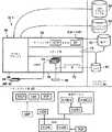
先ず図1を参照すると、ここで教示されている教示の実施形態によるネットワーク12に実装されるマルチキャスト送信システム10が示されている。マルチキャストを確実に行う仮想交換ネットワーク(VXN)14は、ネットワーク12に埋め込まれ、16−1から16−Nという参照番号付けをされた相互接続されたVXNノード1〜Nを含む。トポロジーサーバ18−1〜18−Nは、トポロジーサーバサブシステム20を形成しており、ピアツーピア関係で相互接続される。トポロジーサーバサブシステム20は、1つのトポロジーサーバのみを含みえて、重複がトポロジーサーバサブシステム20の一部を形成しうる。加えて、トポロジーサーバは、VXN14と通信するよう配置される。送信機22−1〜22−Nは、VXN14に接続されて、コンテンツを発行する。受信機24−1〜24−Nは、VXN14へ相互接続されて、発行コンテンツに加入し、受信する。Referring first to FIG. 1, a
VXN14マルチキャストは、送信機22−1から、例えば受信機24−1〜24−N群へデータを配信する効率的方法を提供する。各個々の受信機24へデータのコピーを別個に送信する代わりに、送信機22−1は全ての受信機24−1〜24−Nに対して1つのコピーを送信し、これが反復される。VXN14は、受信機にVXNマルチキャストに参加させ、ネットワーク12を介して実質的にリアルタイムにデータストリームのパケットをマルチキャストおよび交換させる。以下で詳述するように、送信機22−1のさらなる努力または送信なしに、VXNノード16−1〜16−Nは、任意の他のVXNノード16−1〜16−Nへデータストリームのパケットを送信させ、任意の受信機24−1〜24−Nに、任意のVXNノード16−1〜16−Nからデータストリームのパケットを受信させる。VXN14は、このようにして、既存のIPネットワークでは不可能な固有の通信サービスを可能とする。VXN14 multicast provides an efficient way to distribute data from thetransmitter 22-1 to, for example, thereceivers 24-1 through 24-N. Instead of sending a separate copy of the data to each
VXN14のマルチキャスト機能は、ライブコンテンツ、進行中のコンテンツ、およびオンデマンドのコンテンツを含むポイントツーマルチポイントおよびマルチポイントツーマルチポイントマルチキャストを提供する。マルチキャストコンテンツは、概して、異なる要件を有する異なるマルチキャストアプリケーションに関しうる。例えば、リアルタイムのマルチポイントツーマルチポイントマルチメディアマルチキャストアプリケーション(例えば、全国ビデオ会議等)が可能となり、さらに、ポイントツーマルチポイントデータ転送アプリケーション(例えばソフトウェアまたは記録されているまたは進行中のライブイベントコンテンツの配信等の)も可能となる。 The multicast function of VXN 14 provides point-to-multipoint and multipoint-to-multipoint multicast including live content, ongoing content, and on-demand content. Multicast content may generally relate to different multicast applications with different requirements. For example, real-time multipoint-to-multipoint multimedia multicast applications (eg, national video conferencing) are possible, and point-to-multipoint data transfer applications (eg, software or recorded or ongoing live event content) Distribution etc.) is also possible.
進行中のコンテンツに関しては、VXN14は、記録されているデータストリームのパケットの時間をずらすことのできる記録機能を提供する。例えば、送信機は、コンテンツ送信を午後8時に開始して、午後9時に終了するとする。受信機は、このコンテンツを午後8時から午後9時まではライブで受信することができる。加えて、受信機は、このコンテンツを送信中に受信開始することができる。例えば午後8時05分に受信機が午後8時のコンテンツの受信を開始して、マルチキャスト中にマイナス5分時間をずらすことができる(または、5分遅らせることができる)。この結果マルチキャストは、この受信機においては9時05分に終了することになる。さらに、VXN14の記録機能は、進行中のマルチキャストに参加する受信機に対して、マルチキャストを最初からライブの部分までナビゲートする機能、さらにはライブの部分に参加する機能を提供する。さらに、時間をずらされたマルチキャストおよびライブのマルチキャストの間で受信を切り替える機能も提供される。マルチキャスト終了の後に、VXN14は、要求されるとマルチキャストのオンデマンドインスタンスを受信機に提供する。For content in progress, the VXN 14 provides a recording function that can shift the time of packets of the recorded data stream. For example, thetransmitter starts content transmission at 8 pm and ends at 9 pm.The receiver canreceive this content live from 8 pm to 9 pm. In addition, thereceiver can start receiving this content during transmission. For example, thereceiver 8 at 05 pm starts receiving content of 8 pm, can be shifted minus 5 minutes time in a multicast (or can be delayed 5 minutes). As a result, the multicast will end at 9:05 in thisreceiver . Furthermore, the recording function of the VXN 14 provides areceiver that participates in an ongoing multicast, a function that navigates the multicast from the beginning to the live part, and a function that participates in the live part. In addition, the ability to switch reception between timed and live multicasts is also provided. After multicast termination, VXN 14 provides multicast on-demand instances to thereceiver when requested.
図2は、送信機22−1から受信機24−1〜24−11へVXN14を介してポイントツーマルチポイントマルチキャスト送信を実装するシステム10の一実施形態を示すマルチキャストツリーを示し、これは相互接続されたVXNノード16−1〜16−11を含む。しかし、VXN14は任意の数およびトポロジーのVXNノードを含みうる点を了承されたい。トポロジーサーバサブシステム20は、図示のようにローカルゾーン30−1〜30−4のマルチレベル階層で配置されるVXN14を熟知している。一実装例では、各トポロジーサーバ18−1、18−2は、ローカルゾーン30−1〜30−4の1以上を管理する。例えば、トポロジーサーバ18−1は、ローカルゾーン30−1、30−2を管理し、トポロジーサーバ18−2は、30−3、30−4を管理する。トポロジーサーバサブシステム20は、対応するローカルゾーン30−1〜30−4内の各VXNノード16−1〜16−11のローカル状態についての情報を収集する。収集された情報は、例えば、利用可能ポートインタフェースおよび到達可能な隣点を含み、この情報に基づいて、トポロジーサーバサブシステム20はVXNノード16−1〜16−11各対間の経路コストを決定する。FIG. 2 shows a multicast tree illustrating one embodiment of a
ダイクストラベースのアルゴリズムのような最短経路の第1プロトコルを利用して、トポロジーサーバサブシステム20は、エンドポイント対として機能している任意の2つのVXNノード16−1〜16−11間の最適VXN接続(例えば、送信先ノードとして機能しているエッジノードへのルートノード)を含むグローバルマルチキャストトポロジーマップを生成する。もちろん、グローバルマルチキャストトポロジーマップは、同一コストの多数の経路をサポートしえて、一実装例では、次の「ホップアドレス」を、送信先への究極的に最適なルートを選択することで決定してよい。さらに、最適VXN接続は、最少コスト経路分析、負荷、好適な条件分析、およびその他のトラフィック管理係数に基づいて決定されてよい。最適VXN接続は、定期的に最適化を繰り返されて、動的にネットワーク条件を変更するよう満たされ、および、適合されてよい。トポロジーサーバサブシステム20は、グローバルマルチキャストトポロジーマップを利用して、ローカルマルチキャストルーティングトポロジーマップを構築して、VXN14に含まれうるルータ等のその他のネットワークエレメント、および、VXNノード16−1〜16−11を組み込む(populate)。各ローカルマルチキャストトポロジーマップは、グローバルマルチキャストルーティングトポロジーマップのサブセットであり、VXN14の画定領域へ情報を提供する。あるルータについては、例えば、該ルータに対してローカルマルチキャストトポロジーマップのみを提供して、グローバル情報を該ルータから隠すことで、より高いレベルのルーティング保護、および、ルーティングプロトコルトラフィック低減が可能となる。 Using the first protocol with the shortest path, such as Dijkstra-based algorithm, the
図示されているように、送信機22−1は、ルートノードであるVXNノード16−1と通信するよう配置される。送信機22−1は、マルチキャストの一環であるデータストリームのパケットを発行中である。この発行は、特定の実装例では、VXNアドレスと、アプリケーション割り当てされた、または任意に割り当てられたマルチキャスト名称と関連付けられている。一実施形態では、ルートVXNノード16−1が分かっていることで、トポロジーサーバサブシステム20は、VXNアドレス固有のローカルマルチキャストトポロジーマップおよびグローバルマルチキャストルーティングトポロジーマップ32を生成する。ローカルマルチキャストトポロジーマップは、適宜VXN14に組み込まれる。As shown, thetransmitter 22-1 is arranged to communicate with the VXN node 16-1, which is the root node.The transmitter 22-1 is issuing a data stream packet that is part of the multicast. This issue is associated with a VXN address and an application-assigned or arbitrarily assigned multicast name in certain implementations. In one embodiment, knowing the root VXN node 16-1 causes the
受信機24−1〜24−11は、一式のVXNノード16−2〜16−4、16−6〜16−7、および16−9〜16−10と通信するよう配置される。受信機24−1〜24−11は、それぞれ、送信機22−1が発行したデータストリームのパケットに加入している。一例として、受信機24−11は、加入信号をVXNノード16−10へ送る。VXN14加入モデルの一実装例では、暗黙のシグナリングを利用して、受信機24−11等の受信機が、VXNノード16−10等のエッジVXNノードへのパケットを有する加入信号を、提供された最適VXN接続を介して送信することで、マルチキャストアドレスに加入することができる。パケットをVXNアドレスに暗黙に送信する動作により、VXN14は、受信機を、加入信号に関連付けられた送信先アドレスによるマルチキャストに関連付けられたVXNアドレスに加入させることができる。1つの構成においては、受信機は、ヌルパケット(0のデータ長)をVXNアドレスに送信することでVXNアドレスに加入することができる。このヌルパケットは、他の受信機には伝播されない。その代わりに、このヌルパケットは、送信されたヌルパケットの送信先アドレスが表すVXNアドレスへ受信機を加入させることができる。Receivers 24-1 through 24-11 are arranged to communicate with a set of VXN nodes 16-2 through 16-4, 16-6 through 16-7, and 16-9 through 16-10. Each of thereceivers 24-1 to 24-11 subscribes to a data stream packet issued by thetransmitter 22-1. As an example,receiver 24-11 sends a join signal to VXN node 16-10. In one implementation of the VXN14 subscription model, using implicit signaling, areceiver such asreceiver 24-11 was provided a subscription signal with a packet to an edge VXN node such as VXN node 16-10. A multicast address can be subscribed to by transmitting via an optimal VXN connection. The operation of implicitly sending a packet to the VXN address allows
加入信号を受信すると、VXNノード16−10は、送信機22−1が発行したデータストリームのパケットに割り当てられているVXNアドレスに、受信機24−11を関連付ける。発行されたデータストリームのパケットを受信すると、VXNノード16−10は、発行されたデータストリームのパケットを受信機24−11に転送する。一実施形態では、VXNノード16−10は、特定のVXNアドレスに加入している全ての受信機およびその他のVXNノードを識別するポート情報を有するテーブルを維持する。Upon receipt of the join signal, the VXN node 16-10 associates thereceiver 24-11 with the VXN address assigned to the data stream packet issued by thetransmitter 22-1. Upon reception of the issued data stream packet, the VXN node 16-10 transfers the issued data stream packet to thereceiver 24-11. In one embodiment, the VXN node 16-10 maintains a table with port information identifying allreceivers and other VXN nodes that are subscribed to a particular VXN address.
さらに、VXNノード16−10はデータストリームのパケットに加入していないので、VXNノード16−10は、加入信号を送信するが、この加入信号は、受信機24−11から、ルートノードであるVXNノード16−1への元の加入信号の派生物として捉えることができる。そしてVXNノード16−1は、発行されたデータストリームのパケットを、VXNノード16−10に転送して、今度はこれが、この発行されたデータストリームのパケットを受信機24−11へ転送する。送信機22−1から受信機24−11へのマルチキャスト部分については、VXNノード16−1からVXNノード16−10への経路は、エンドポイント(つまり、ルートVXNノード16−1およびエッジVXNノード16−10)が画定する接続が実現されるまで、加入信号および派生的な加入信号の形式で加入信号が連続して逆進する(successively regressively traverse)最適VXN接続34を有する。この最適VXN接続34は、トポロジーサーバサブシステム20に格納されているグローバルマルチキャストルーティングトポロジーマップ32に含まれており、ローカルマルチキャストルーティングトポロジーマップによりVXN14内に実装される。Further, since the VXN node 16-10 has not joined the packet of the data stream, the VXN node 16-10 transmits a join signal, which is sent from thereceiver 24-11 to the VXN which is the root node. It can be understood as a derivative of the original join signal to the node 16-1. The VXN node 16-1 then forwards the issued data stream packet to the VXN node 16-10, which in turn forwards the issued data stream packet to thereceiver 24-11. For the multicast portion fromtransmitter 22-1 toreceiver 24-11, the path from VXN node 16-1 to VXN node 16-10 is the endpoint (ie, root VXN node 16-1 and edge VXN node 16). to -10) is connected to define is achieved, with a pressurized No.incoming in the form of subscriber signals and consequential subscriber signal to reverse sequentially (successively regressively traverse)
さらなる例である受信機24−9に関しては、受信機24−9は、受信機24−9へのエッジノードとして機能するVXNノード16−8へ加入信号を送る。加入処理を行う際、VXNノード16−8は、内部にインストールされているローカルマルチキャストトポロジーマップのコンテンツに基づいて、VXNノード16−10へ派生的な加入信号を送信する。VXNノード16−10は既にデータストリームのパケットに加入済なので、VXNノード16−10は、第2の加入信号をVXNノード16−1へ送らない、というのも、受信機24−9に関しては、VXNノード16−1およびVXNノード16−8のエンドポイント間の最適仮想交換ネットワーク接続36が実現されているからである。VXNノード16−10の完全な振る舞いに関しては、ひとたび受信機24−10が同様にデータストリームのパケットに加入すると、VXNノード16−10はデータストリームのパケットのマルチキャストポイントとなる。データストリームのパケットのインスタンスを受信すると、VXNノード16−10は、データストリームのパケットのインスタンスを3つ送信する。受領機器はそれぞれ、受信機24−11、VXNノード16−9、およびVXNノード16−8である。より一般的には、例えば、VXNノード16−1〜16−11のそれぞれが、受信した発行データストリームのN個のインスタンスを、N個の受領機器(他のVXNノードまたは受信機を含みうる)に対してマルチキャストするマルチキャストポイントとして適合される。For thereceiver 24-9 is a further example,the receiver 24-9 sends a join signal to VXN node 16-8 which functions as an edge node to thereceiver 24-9. When performing the subscription process, the VXN node 16-8 transmits a derivative subscription signal to the VXN node 16-10 based on the contents of the local multicast topology map installed therein. Since the VXN node 16-10 has already joined the packet of the data stream, the VXN node 16-10 does not send a second join signal to the VXN node 16-1, because for thereceiver 24-9, This is because the optimum virtual switching network connection 36 between the endpoints of the VXN node 16-1 and the VXN node 16-8 is realized. With respect to the full behavior of the VXN node 16-10, once thereceiver 24-10 has joined the data stream packet as well, the VXN node 16-10 becomes a multicast point for the data stream packet. Upon receiving an instance of a data stream packet, the VXN node 16-10 transmits three instances of the data stream packet.The receiving devices are thereceiver 24-11, the VXN node 16-9, and the VXN node 16-8, respectively. More generally, for example, each VXN node 16-1~16-11 is, the N instances of the received issuing data stream, (which may include other VXN nodes orreceivers) Npieces ofreceiving equipment Is adapted as a multicast point to multicast to.
グローバルマルチキャストルーティングトポロジーマップ32の作成機能を有する他のVXNノードのマルチキャスト機能についても例示する。例えば、VXNノード16−4と通信するよう配置された受信機24−3〜24−5等の2つ以上の受信機が、特定のVXNノードに加入する場合が考えられる。グローバルマルチキャストルーティングトポロジーマップ32は、他の種類のVXN14の振る舞いを示している。例えば、VXN14の一部であるVXNノード16−5は、受信機24−5に近接して配置されているが、VXNノード16−5は、上述のVXNアドレスを割り当てた送信機22−1によるマルチキャストのグローバルマルチキャストルーティングトポロジーマップ32の一部ではない、というのも、VXNノード16−5に関連する経路コストが高すぎるからである。動作において、VXN14のVXNノード16−1〜16−11のマルチキャスト機能および振る舞いは、ローカルマルチキャストルーティングトポロジーマップによる最適仮想交換ネットワーク接続による暗黙のシグナリングによりデータストリームのパケットを伝播する。The multicast function of another VXN node having the function of creating the global multicast
図3は、マルチポイントツーマルチポイントについて実装されたマルチキャスト送信システムの一実施形態を示す。本実施形態では、送信機22−1および22−2という2つの送信機があり、これらはそれぞれ受信機24−12および24−3でもある。送信機22−1および22−2は、同じルートVXNノード16−1を利用して、送信機22−1および22−2のデータストリームのパケットは、データストリームのパケット伝播用に同一のVXNアドレスを有する。VXN14の振る舞いは、その他の面では、図2に示し説明したものと同じである。FIG. 3 illustrates one embodiment of a multicast transmission system implemented for multipoint-to-multipoint. In the present embodiment,there aretwotransmitters thattransmitter 22-1 and 22-2,these are respectively anyreceiver 24-12 and 24-3.The transmitters 22-1 and 22-2 utilize the same root VXN node 16-1, and the packets of the data streams of thetransmitters 22-1 and 22-2 have the same VXN address for packet propagation of the data stream. Have The behavior of
図4は、マルチポイントツーマルチポイントについて実装されたマルチキャスト送信システムの別の実施形態を示す。本実施形態では、2つのグローバルマルチキャストルーティングトポロジーマップ(つまり、各送信機22−1、22−2について1つずつ)を生成する。各送信機22−1、22−2に関連付けられたデータストリームのパケットはそれぞれ別個のVXNアドレスに加入しており、受信機24−1〜24−12はマルチキャスト各々に同時に加入する。このマルチポイントツーマルチポイントでは、各送信機/受信機対(22−1、24−12);(22−2、24−4)が発行実体であり、送信機/受信機(22−1、24−12);(22−2、24−4)を含む各受信機が、自身以外の各発行機器からの受信を待ち受ける。マルチポイントツーマルチポイントマルチキャストのサイズが大きくなると、受信機数は送信機数をはるかに上回るようになり、VXN14は、管理努力なしにエンドユーザに対するポート利用に関する効率およびトランスペアレンシーを同じに保ちつつ、これら非対称な構成へのスムーズな移行を可能とする。受信機の選択も、送信機または発行機器のコンテンツの他の視聴者に影響を与えることなく動的に変更させうる。発行されたデータストリームのパケットに加入するのにさらなるVXNノードを利用することで、潜在的な受信機の数は、多数のVXNノードを層状化することにより容易に増加しえて(例えば、VXNノード16−10、16−8、16−6、16−7の層状化を参照のこと)、数百万の受信機を超える数の視聴者を含む任意のサイズの視聴者が生じうる。VXN14をサイズ調整可能とすることで、一方だけのまたは二重のポイントツーポイント通信から、ポイントツーマルチポイントマルチキャスト、ひいては、ブロードキャストを含むマルチポイントツーマルチポイントマルチキャストというように、範囲を広げることができる。VXNノードの層状化機能により、VXN14は、この機能の範囲内で、管理的介入なしに動的およびシームレスな遷移をすることができる。FIG. 4 illustrates another embodiment of a multicast transmission system implemented for multipoint-to-multipoint. In the present embodiment, two global multicast routing topology maps (that is, one for eachtransmitter 22-1 and 22-2) are generated. The packets of the data stream associated with eachtransmitter 22-1 and 22-2 each subscribe to a separate VXN address, andreceivers 24-1 to 24-12 join each multicast simultaneously. In this multipoint-to-multipoint, eachtransmitter /receiver pair (22-1, 24-12); (22-2, 24-4) is an issuing entity, and thetransmitter /receiver (22-1, 24-12); eachreceiver including (22-2, 24-4) waits for reception from each issuingdevice other than itself. As the size of multipoint-to-multipoint multicast increases, the number ofreceivers will far exceed the number oftransmitters , and
図5は、VXN14が時間1から時間2へ遷移する際のトポロジー管理の一実施形態を示す。特に、例示されている遷移には、受信機を見失うこと、受信機の追加、および、総体VXNノード利用可能性および/または関連する経路コストにおける変更、が含まれる。時間1から時間2への遷移において、受信機24−6は、マルチキャストへの参加を終了する決定をする。受信機24−6は、停止信号をVXNノード16−6へ送り、これによりデータストリームのパケットの受信機24−6への転送が停止される。別の実装例では、受信機24−6は、特定のVXN14構成が設定するよう、VXNノード16−6またはトポロジーサーバサブシステム20が要求する接続試験用パケット(ping)またはKEEP−ALIVE信号を送信しないことにより、暗黙に接続停止する。本実装例においては、VXNノード16−6またはトポロジーサーバサブシステム20は、適宜、ある期間中に接続試験用パケットを受信しないことにより、停止条件を暗黙に示す。この場合、VXNノード16−6は、VXNノード16−6を介したデータストリームのパケットに加入するさらなる受信機またはVXNノードを有さないので、VXNノード16−6はVXNノード16−8へ停止信号を送信する。これを受けてVXNノード16−8は、内部のテーブルの情報を更新して、VXNノード16−8に対するデータストリームのパケット送信を停止する。FIG. 5 illustrates one embodiment of topology management when the
VXN14は、受信機にいかなるときにもマルチキャストセッションの停止を可能とするだけではなく、VXN14は、マルチキャストセッションの継続中の任意の時点での受信機の参加を可能とする。時間1から時間2への遷移において、受信機24−13は、自身に対して一番近いエッジノードであるVXNノード16−10に対して、加入信号(一実装例では空のパケットである)を送信することで、マルチキャストに参加する。VXNノード16−10は、既にデータストリームのパケットを受信および転送しており、受信機24−10、24−13両方に対するマルチキャストポイントとして機能する。
VXNノードのコンプレックス内のフォールトからの復帰は、送信機および受信機双方が定期的に通信経路を自動再構築するVXNアドレススキームにより自動的に行われる。各データ送信処理により、VXN14はフォールトがあっても高い信頼性および高品質のユーザ体験を可能とすることができる。例えば、時間1から時間2へ遷移する際に、受信機24−2が加入しているVXNノード16−3でフォールトが起こったとする。このフォールトを検出すると、トポロジーサーバサブシステム20は、新たなグローバルマルチキャストルーティングトポロジーマップおよび関連するローカルマルチキャストルーティングトポロジーマップを生成する。一実施形態では、ローカルマルチキャストルーティングトポロジーマップを有するVXN14を再生するのではなくて、トポロジーサーバサブシステム20は、もしあれば先行するローカルマルチキャストルーティングトポロジーマップと、新たなローカルマルチキャストルーティングトポロジーマップとの間に、差異を表すデルタローカルマルチキャストルーティングトポロジーマップを生成する。デルタローカルマルチキャストルーティングトポロジーマップを、VXN14およびネットワークエレメント(VXNまたはルータに関わらず)を介して伝播させ、デルタローカルマルチキャストルーティングトポロジーマップを利用して既存のローカルマルチキャストルーティングトポロジーマップを更新する。受信機24−2の例に戻ると、この更新はリアルタイムに行われ、受信機24−2は、実質的に即座にVXN16−4に加入して、マルチキャストへの参加を続行する。Recovery from faults in the VXN node complex is done automatically by a VXN address scheme in which both thetransmitter and thereceiver automatically reconfigure the communication path periodically. Each data transmission process allows the
一実施形態では、VXN14には、独立してまたは協働して、遅れて参加した受信機にマルチキャストに参加させる機能を提供する3つの特徴を有する(つまり、エッジVXNノードは、説明した即座の加入、進行中のアクセス、およびオンデマンドのアクセスを可能とする)。受信機24−13に戻ると、このような受信機が進行中の送信に加入するとき、受信機はライブのフィードを受信してよく、または、遅れて参加した受信機24−13は、マルチキャストの開始からライブのフィードまでの任意の時点で進行中のマルチキャストにアクセスすることができるようになる。本実施形態では、VXNノード16−9はマルチキャストを格納しており、進行中のアクセスを提供する。この格納機能は、後でさらに詳述するが、完了の後のマルチキャストへのオンデマンドアクセスを提供する。ブロードキャスト中に、VXN14は、受信機がライブアクセスと進行中のアクセスとの間でスイッチすることを可能とする。In one embodiment,
図1から図5に記載した実施形態は、非制限的な実施例であり、そのトポロジー、送信機数、受信機数は単に利用可能なものを例示したにすぎず、利用可能および動作可能なものを網羅しているわけではない。本発明の教示には他のトポロジーおよび送信機/受信機のサイズの調整機能も含まれている。The embodiment described in FIGS. 1-5 is a non-limiting example, and its topology, number oftransmitters, number ofreceivers are merely examples of what is available, and is available and operable. It does not cover everything. The teachings of the present invention include other topologies andtransmitter /receiver size adjustment functions.
図6は、エンジン40および多数のデータベース、コンフィギュレーションデータベース42、トポロジーデータベース44、およびコスト分析データベース46を含むトポロジーサーバ18−1のアーキテクチャの一実施形態を示す。トポロジーサーバはVXN14と通信するよう配置され、一例では、ルータとして示されているネットワークエレメント48〜54間で画定される幾らかの異なる経路により相互接続されうるVXNノード16−11および16−4間の接続をモニタする。 FIG. 6 illustrates one embodiment of the architecture of topology server 18-1 including
トポロジーサーバ18−1は、VXNノード16−11、16−4、および関連する相互接続ネットワークエレメント48〜54について熟知している。VXN14のこの部分のトポロジーは、グローバルマルチキャストルーティングトポロジーの一部としてトポロジーデータベース44に格納される。エンジン40は、この情報を利用して、ダイクストラアルゴリズムのようなアルゴリズムを利用して最短経路の第1計算を行う。これら計算から得られた最適VXN接続をコスト分析データベース46に格納する。例えば、エンジン40は、VXNノード16−11から、ルータ48、ルータ52、そしてVXNノード16−4への最適VXN接続56が、VXNノード16−11とVXNノード16−4との間の最適経路であると決定する。この情報をVXNノード16−11、16−4およびネットワークエレメント48、52に提供する図示されたVXN14の部分のローカルマルチキャストルーティングトポロジーマップは、VXN14を組み込むべくコンフィグレーションデータベース42に格納される。加えて、VXNトポロジー変更が起きると、エンジンは、エンジンは、グローバルマルチキャストルーティングトポロジーマップ、最適VXN接続、ローカルマルチキャストルーティングトポロジーマップ、および、デルタローカルマルチキャストルーティングマップを再計算する。 Topology server 18-1 is familiar with VXN nodes 16-11, 16-4, and associated interconnect network elements 48-54. The topology of this part of
図7は、トランスポート層62およびハードウェアスペース64に重畳されるAPI60を有するVXNノード16−1の層状化アーキテクチャの一実施形態である。トランスポート層62は、API60からのサービス要求に応答して、ネットワーク層等の低レベル層にサービス要求を発行する。例示されている実装例では、トランスポート層62は、好適には一式のプロトコルである1以上のプロトコルを含む。例示されたプロトコルは、RTCP、RAS,RTP、UDP、H.450.3、H.450.2、H.450.1、H.235、H.245、H.225、およびTCPを含む。しかし、トランスポート層62は任意の1つのプロトコル(または一式のプロトコル)を含みうることを理解されたい。VXNスタック66は、チャネルマネージャ68、VXN層70、ファイルシステム層72、メディア層74、およびゲートウェイ層76を含む。VXNスタックのこれらコンポーネントは、ハードウェアスペース64にあるライブデータベース80、進行中データベース82、ルックアップデータベース84、およびVXNアドレステーブルデータベース86にアクセスを有する。概して、VXN層70でデータストリームのーパケット90を受信すると、チャネルマネージャ68は、VXNアドレステーブルデータベース86にアクセスして、VXNノード16−1のこの特定のVXNアドレスされたマルチキャストに加入している加入機器数を識別する。N個の加入機器各々について、VXN層70は、N個のマルチキャストポイント92を利用してデータストリームのパケット90を複製して、データストリームのパケット90のN個のインスタンスをN個の加入機器(番号94参照)に同時送信する。他方で、チャネルマネージャ68が、それについて加入要求を受信するデータストリームのパケットへの加入機器ではない場合、チャネルマネージャ68はルックアップデータベースを利用して受信されたアプリケーションに割り当てられた、または任意に構築されたマルチキャスト名称を、適正なVXNアドレスに変換してよい。FIG. 7 is one embodiment of a layered architecture of VXN node 16-1 having
ファイルシステム層72は、データストリームのパケット90のコピーを保持し、ライブのマルチキャストのライブデータベース80にファイルを構築する。メディア層74は、例えば、ライブデータベース80を繰り返しサンプリングすること、または、データストリームのパケット90を進行中のデータベース82に既存のファイルに連結することにより、ライブマルチキャストの進行中データベース82に進行中ファイルを構築する。この進行中ファイルは、ライブマルチキャストが進行中に時間をずらされたマルチキャストを提供するよう設けられてよい。進行中ファイルは、受信機がデータストリームのパケットをトランスペアレントに且つシームレスに受信するよう、VXNノードから配信される。ゲートウェイ層は、VXNのデータストリームのパケット90および進行中ファイルを、HTTPまたはSIPのような別のプロトコルに変換して、受信機が、ブラウザまたはその他の既存のソフトウェアアプリケーションの利用によりコンテンツ受信できるようにする。または、ゲートウェイ層は、進行中ファイルを別のプロトコルだけに変換する。VXN14およびデータベース80、82が提供する時間をずらす機能は、記録されているコンテンツの前の部分を対象受信機に対して同時に処理する間、メディアコンテンツを記録することを可能とする。特に、この方法は、ライブマルチキャストが継続している間にも進行中のまたは時間をずらされたコンテンツへのアクセスを実現する。The
一実装例では、VXN14および例示されたVXNノード16−1は、64ビットのアドレススキームを含みうるフラットなアドレススキームを利用する。VXNスタック66およびそれが実現するプロトコルは、IPレベルで実装されるわけではない。VXNスタック66は、VXN14がマルチキャストネットワークを、個々のVXNノード間のユニキャストの対話に関係するVXNノード16−1〜16−Nから構築する際に、トランスポート層62に重畳される。このアーキテクチャでは、VXN14は既存のユニキャストIPネットワークの上に実装される。さらに、このアドレススキームでは、最適仮想交換ネットワーク接続と提携しているVXN14の各相互接続されたノードは、N個の受領機器各々について、VXNアドレスに関連付けられたポートアドレスと受信機IDとを含む。この情報は、ハードウェアスペース64に存在するVXNアドレステーブルデータベース86と関連付けられる。In one implementation,
上述したように、接続試験用パケットメッセージまたはKEEP−ALIVE信号が、加入機器であるエンドポイントから特定のマルチキャストポイント(つまりVXNノード)へ定期送信されて、加入をアクティブなステータスに保つ。一実装例では、KEEP−ALIVE信号は、さらに、送信データが関連付けられていないSEND動作であり、加入構築に利用されうるようなものであってよい。これは、加入がアクティブであり、受領機器がデータ受信を行うことが依然できていることを示す。KEEP−ALIVE信号が特定のタイムアウト間隔(例えば30秒)の間受信されない場合、エンドポイントは加入されていないとみなされ、その後はそのエンドポイントに対しては、再度加入が構築されるまで、データを送信しない。As described above, a connection test packet message or KEEP-ALIVE signal is periodically transmitted from an endpoint that is a subscriberdevice to a specific multicast point (ie, a VXN node) to keep the subscription in an active status. In one implementation, the KEEP-ALIVE signal may further be a SEND operation with no associated transmission data and may be used for subscription establishment. This indicates that the subscription is active and thereceiving device is still able to receive data. If a KEEP-ALIVE signal is not received for a particular timeout interval (eg 30 seconds), the endpoint is considered not subscribed, after which the endpoint receives data until a subscription is established again. Do not send.
マルチキャストポイントから接続停止する場合または未加入である場合には、マルチキャストポイントからのデータ受信を停止することを望むエンドポイント(VXNノード、受信機に関わらず)は、VXNポイントへのKEEP−ALIVEパケット送信を停止する。所定のタイムアウト間隔の後に、VXNマルチキャストポイントは、この特定のエンドポイントへのデータ送信を停止する。あるエンドポイントが未加入である場合には、再度加入するべく、VXNマルチキャストポイントに対して空のデータパケットを送信する必要がある。加入に利用されたのと同じ空のデータパケットをKEEP−ALIVEに利用するので、KEEP−ALIVE信号が遅れている理由からあるエンドポイントが未加入である場合、次に到着するKEEP−ALIVE信号を加入要求とみなし、そのエンドポイントをVXNマルチキャストポイントとして再度加入させる。When the connection is stopped from the multicast point or when it is not yet joined, the endpoint (regardless of the VXN node orreceiver ) that wishes to stop receiving data from the multicast point receives the KEEP-ALIVE packet to the VXN point. Stop sending. After a predetermined timeout interval, the VXN multicast point stops sending data to this particular endpoint. If an endpoint has not joined, an empty data packet needs to be sent to the VXN multicast point to join again. Since the same empty data packet used for subscription is used for KEEP-ALIVE, if a certain endpoint is not subscribed because the KEEP-ALIVE signal is delayed, the next arriving KEEP-ALIVE signal is It is regarded as a subscription request and the endpoint is rejoined as a VXN multicast point.
図8は、送信機および受信機の層状化アーキテクチャの一実施形態を示す。送信機/受信機(24−3、22−2)、送信機22−1、および受信機24−2は、各々、VXN14に接続される。送信機/受信機(24−3、22−2)は、データトランスポート層100、データ制御層102、およびアプリケーション層104を含む。送信機/受信機(24−3、22−2)の機能を送信するにあたっては、エンコーダ106は、音声−映像フレームをデジタル化および符号化して、デマルチプレクサ108へ転送して、利用されているプロトコルの種類に応じて幾らかのチャネル110またはストリームに分割する。図示されているように、ストリーム110はVXNのデータストリームのパケットとしてVXN14を介して送信される。FIG. 8 illustrates one embodiment of atransmitter andreceiver layered architecture.Transmitter /receiver (24-3, 22-2),transmitter 22-1, andreceiver 24-2 are each connected to VXN14.The transmitter /receiver (24-3, 22-2) includes a
データストリームのパケット送信前に、送信機24−3が、処理によりVXN14のVXNノードのいずれかに接続すると(どのノードを選択するかはアプリケーションによる)、送信機24−3には有効なVXNアドレスが割り当てられる。こうすることで、他の受信機およびVXNノードは、この割り当てられたVXNアドレスを利用してこのアプリケーションインスタンスを参照することができる。送信機/受信機(24−3、22−2)の受信機の機能に関しては、VXN14からデータトランスポート層100で受信したチャネル112またはストリームが、マルチプレクサ114で合成されて、デコーダ116でデコードされて、送信機/受信機(24−3、22−2)への提供に備えられる。If thetransmitter 24-3 is connected to one of the VXN nodes of the
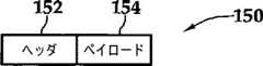
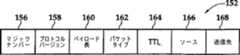
別の例としては、送信機22−1は、同様のデータトランスポート層118、データ制御層120、チャネル124を含むアプリケーション層122構成、デマルチプレクサ126、およびエンコーダ128をそれぞれ含みうる。送信機/受信機(24−3、22−2)および送信機22−1に反して、VXNノードのゲートウェイ機能により、受信機24−2は、VXNのデータストリームのパケットではなくて、HTTPストリームを受信することができるようになり、これにより、コンテンツの潜在的な視聴者が増える。受信機24−2はさらに、データトランスポート層130、データ制御層132、およびアプリケーション層134を含む。チャネル136はデータトランスポート層130で受信され、ブラウザ140処理の前にマルチプレクサ138で多重化される。図9Aおよび図9Bは、上述のデータストリームのパケットであってよいVXNパケット構造150の一実施形態を示す。図9Aを参照すると、VXNパケット150は、ヘッダ152とペイロード154とを含む。上述したように、VXNパケット150は送信機から受信機へ、VXN14を介して、暗黙に、VXNパケット150の既存のシグナリング情報エレメントに対して新たなパラメータの追加なしに、送信される。図9Bを参照すると、一実装例では、ヘッダ152は、マジックナンバーセグメント156、プロトコルバージョンセグメント158、ペイロード長セグメント160、パケットタイプセグメント162、有効期間(TTL)セグメント164、ソースセグメント166、および送信先セグメント168を含む7つのセグメントを含む。以下の表1:VXNパケットセグメント定義はVXNパケットセグメントを定義し、表2:VXNパケットタイプは、VXNパケットタイプを定義する。
符号化されたVXNパケット150の一実施形態では、以下の表3:VXNパケット疑似コードに表された疑似コードを利用することができる。
図6から図9Bに記載する実施形態は、非制限な実施例として示されており、コンポーネント、ネットワークアーキテクチャ、およびプロトコルは、利用可能なものを例示したにすぎず、利用可能なものおよび動作可能なものを網羅しているわけではない。本発明の教示には他のコンポーネント、ネットワークアーキテクチャ、およびプロトコルが含まれている。 The embodiment described in FIGS. 6-9B is shown as a non-limiting example, and the components, network architecture, and protocols are merely illustrative of what is available, what is available and operable It is not an exhaustive list. The teachings of the present invention include other components, network architectures, and protocols.
図10は、ここで開示する教示によるマルチキャスト送信方法の一実施形態のフローチャートである。ブロック180で、相互接続されたノードおよびネットワークエレメントの仮想交換ネットワークが、ネットワーク内に構築される。ブロック182で、相互接続されたノードの複数の対の間の経路コストが、仮想交換ネットワークと通信するトポロジーサーバサブシステムにより決定される。経路コスト計算には、前述の最適経路分析が含まれうることに留意されたい。これら経路コストに基づいて、トポロジーサーバサブシステムは、ブロック184で、グローバルマルチキャストルーティングトポロジーマップを生成する。そしてブロック186で、トポロジーサーバサブシステムがグローバルマルチキャストルーティングトポロジーマップを利用して、ローカルマルチキャストルーティングトポロジーマップを生成する。 FIG. 10 is a flowchart of one embodiment of a multicast transmission method according to the teachings disclosed herein. At
ブロック188で、これらローカルマルチキャストルーティングトポロジーマップが適宜相互接続されたノードおよびネットワークエレメントに対して配信される。ブロック190で、データストリームのパケットの送信機が、VXNの相互接続されるノードのうち1つであるルートノードと通信するよう配置される。このステップで、ルートノードは、送信機が発行したデータストリームのパケットを受信してよい。ブロック192で、相互接続されるノードの一部を形成する一式のエッジノードと通信するよう配置される受信機は、加入信号をそれぞれエッジノードに対して相互に送信する。ブロック194で、連続して逆進する派生的な加入信号が、最適仮想交換ネットワーク接続を介して、一対のエンドポイントが定義する接続が達成されるまで伝播される。各受信機については、一対のエンドポイントがそれぞれルートノードおよびエッジノードの1つである。ブロック196で、データストリームのパケットが、間接的なシグナル伝達により、最適仮想交換ネットワーク接続を介して送信機から複数の受信機へ送信される。At
ブロック198で、データストリームのパケットがオンデマンド用に(発行の後(post-publication))、且つ、進行中のアクセス用に格納される。決定ブロック200で、もしもVXNのトポロジーが変更された場合には、グローバルマルチキャストトポロジールーティングマップをブロック202で再計算する。このとき、ローカルマルチキャストトポロジールーティングマップおよびデルタローカルマルチキャストトポロジールーティングマップを再計算してよい。デルタローカルマルチキャストトポロジールーティングマップは、方法がブロック204へ進むと、ネットワークを介して伝播され、さらなるデータストリームのパケットを発行する。決定ブロック200でトポロジーが変更されなかった場合には、方法はさらにブロック204へ進む。ブロック204からは、ブロック196へ戻る。 At
本発明を、例示的実施形態を参照して記載してきたが、この記載は制限的な意味合いで理解されるべきものではない。本発明の様々な変形例、例示的な実施形態の組み合わせ、およびその他の実施形態が、本記載に基づいて当業者には明らかである。故に、添付請求項はこのような変形例あるいは実施形態を包括することを意図している。 While this invention has been described with reference to illustrative embodiments, this description is not to be construed in a limiting sense. Various modifications, combinations of exemplary embodiments, and other embodiments of the invention will be apparent to those skilled in the art based on the description. Accordingly, the appended claims are intended to cover such modifications or embodiments.
Claims (10)
Translated fromJapanese前記ネットワーク(12)に埋め込まれ、複数の相互接続されたノード(16−1〜16−N)を有する仮想交換ネットワーク(14)と、
前記複数の相互接続されたノード(16−1〜16−N)のなかのルートノードと通信するよう配置され、仮想交換ネットワークアドレスを含むデータストリームのパケット(150)を発行する送信機(22−1〜22−N)と、
前記複数の相互接続されたノード(16−1〜16−N)のうちの一式のエッジノードと通信するよう配置される複数の受信機(24−1〜24−N)と、
前記仮想交換ネットワーク(14)と通信するよう配置されて、前記仮想交換ネットワーク(14)を熟知しているトポロジーサーバサブシステム(20)と、
前記トポロジーサーバサブシステム(20)により生成され、複数の最適仮想交換ネットワーク接続を含むグローバルマルチキャストルーティングトポロジーマップと、
前記トポロジーサーバにより生成され、前記複数の最適仮想交換ネットワーク接続に沿って配置される複数のローカルマルチキャストルーティングトポロジーマップと
を備え、
前記複数の受信機(24−1〜24−N)の各々は、前記一式のエッジノードのなかのエッジノードのいずれかにそれぞれ加入して、前記発行されたデータストリームのパケット(150)を受信し、
前記複数の最適仮想交換ネットワーク接続の各々は、前記ルートノードと前記一式のエッジノードのなかの前記エッジノードのいずれかとを含む一対のエンドポイントにより画定され、
前記複数のローカルマルチキャストルーティングトポロジーマップの各々は、前記グローバルマルチキャストルーティングトポロジーマップのサブセットであることで前記仮想交換ネットワーク内の画定された前記複数の最適仮想交換ネットワーク接続よりなる領域にルーティング情報を提供し、
前記データストリームのパケット(150)は、前記複数のローカルマルチキャストルーティングトポロジーマップにより前記複数の最適仮想交換ネットワーク接続を介した間接的なシグナル伝達により伝播され、
前記複数の最適仮想交換ネットワーク接続と提携した前記複数の相互接続されたノード(16−1〜16−N)の各々は、前記一式のエッジノードのいずれかから前記ルートノードへの前記複数の最適仮想交換ネットワーク接続の各々沿いに連続して逆進的に前記発行されたデータストリームのパケット(150)を受信するよう加入するシステム。A system (10) for multicast transmission of data via a network (12),
A virtual switching network (14) embedded in the network (12) and having a plurality of interconnected nodes (16-1 to 16-N);
Said plurality of arranged to communicate with a root node of among the interconnected nodes (16-1 to 16-N),the transmitter issuing the packet (150) of a data stream including a virtual exchange networkKua dress ( 22-1 to 22-N),
A plurality ofreceivers (24-1 to 24-N) arranged to communicate with a set of edge nodes of the plurality of interconnected nodes (16-1 to 16-N);
A topology server subsystem (20) arranged to communicate with the virtual switching network (14) and familiar with the virtual switching network (14);
A global multicast routing topology map generated by the topology server subsystem (20) andincluding a plurality of optimal virtual switched network connections;
A plurality of local multicast routing topology maps generated by the topology server and arranged along the plurality of optimal virtual switching network connections;
Each of the plurality ofreceivers (24-1 to 24-N) subscribes to one of the edge nodes in the set of edge nodes and receives the packet (150) of the issued data stream. And
Each of the plurality of optimal virtual switching network connections is defined by a pair of endpoints including the root node and any of the edge nodes in the set of edge nodes;
Each of the plurality of local multicast routing topology maps is a subset of the global multicast routing topology map to provide routing information toan areacomposed of the plurality of optimum virtual switching network connections definedin the virtual switching network. ,
The packet (150) of the data stream is propagated by indirect signaling via the plurality of optimal virtual switching network connections by the plurality of local multicast routing topology maps;
Each of the plurality of interconnected nodes (16-1 to 16-N) affiliated with the plurality of optimal virtual switching network connections is configured such that the plurality of optimal nodes from any of the set of edge nodes to the root node. A systemthat subscribes to receive packets (150) of the issued data stream continuously and reversibly along each of the virtual switched network connections .
トポロジーサーバサブシステムが前記ネットワーク(12)内のネットワークエレメントおよび複数の相互接続されたノード(16−1〜16−N)の仮想交換ネットワーク(14)を構築する段階と、
前記仮想交換ネットワーク(14)と通信する前記トポロジーサーバサブシステム(20)が、前記相互接続されたノード(16−1〜16−N)の複数の対の間の経路コストを決定する段階と、
前記相互接続されたノード(16−1〜16−N)の複数の対の間の前記経路コストに基づいて、前記トポロジーサーバサブシステム(20)が、各々が一対のエンドポイントにより画定される複数の最適仮想交換ネットワーク接続を含むグローバルマルチキャストルーティングトポロジーマップを生成する段階と、
前記グローバルマルチキャストルーティングトポロジーマップに基づいて、前記トポロジーサーバサブシステム(20)が、各々が前記グローバルマルチキャストルーティングトポロジーマップのサブセットであることで前記仮想交換ネットワーク(14)内の画定された前記複数の最適仮想交換ネットワーク接続よりなる領域にルーティグ情報を提供する複数のローカルマルチキャストルーティングトポロジーマップを生成する段階と、
前記トポロジーサーバサブシステムが、前記複数のローカルマルチキャストルーティングトポロジーマップを、前記相互接続されたノード(16−1〜16−N)およびネットワークエレメントに循環させる段階と、
前記複数の相互接続されたノード(16−1〜16−N)のなかの1つのルートノードが、送信機(22−1〜22−N)が発行したデータストリームの1パケットを受信する段階と、
複数の受信機(24−1〜24−N)が、複数の加入信号を、前記複数の相互接続されたノード(16−1〜16−N)のうちの一式のエッジノードへ送信する段階と、
前記複数の受信機(24−1〜24−N)の各々について、前記ルートノードと前記エッジノードのうちの1つとからなる前記一対のエンドポイントにより画定される前記最適仮想交換ネットワーク接続に含まれる前記複数の相互接続されたノードのそれぞれが派生的な加入信号を送信するまで、前記最適仮想交換ネットワーク接続を介して、前記複数の相互接続されたノードが複数の前記派生的な加入信号を連続して逆進的に伝播させる段階と、
前記データストリームのパケットを、前記複数の最適仮想交換ネットワーク接続を介した間接的なシグナル伝達により、前記相互接続されたノードが、前記送信機(22−1〜22−N)から前記複数の受信機(24−1〜24−N)へ送信する段階と
を備える方法。A method for multicast transmission of data via a network (12),
A topology server subsystem constructing a virtual exchange network (14) of network elements in the network (12) and aplurality of interconnected nodes (16-1 to 16-N);
A step whereinthe topology server subsystem that communicates with the virtual switching network (14)(20), to determine the path cost between a plurality of pairs of the interconnected nodes (16-1 to 16-N),
Based on the path cost between a plurality of pairs of the interconnected nodes (16-1 to 16-N), the topology server subsystem (20)is a plurality defined by a pair of endpoints. Generating a global multicast routing topology map that includes an optimal virtual switched network connection of
On the basis of the global multicast routing topology map, the topology server subsystem(20), each said global multicast routing topology map the virtual switching network by a subset of (14) inthe plurality of defined optimal Generating a plurality of local multicast routing topology maps that provide routing information foran areacomprising virtual switched network connections ;
The topology server subsystem circulating the plurality of local multicast routing topology maps to the interconnected nodes (16-1 to 16-N) and network elements;
One root node among the plurality of interconnected nodes (16-1 to 16-N)has the steps of receiving one packettransmitter (22-1 to 22-N) is issued by the data stream ,
A plurality ofreceivers (24-1 to 24-N) transmittinga plurality of join signals to a set of edge nodes of the plurality of interconnected nodes (16-1 to 16-N); ,
For each of the plurality ofreceivers(24-1~24-N),contained in theprior SL root node and theoptimum virtual switched network connections thatwill be definedby the pair endpoint consisting of one of the edge node untilsaid each of the plurality of interconnected nodes sends consequential subscriber signals, via the optimal virtual switched networkconnections, the plurality of interconnected nodes a plurality ofthe consequential subscriber signal A continuous and reverse propagation phase;
Packets of said data stream, by indirect signaling via the plurality of optimal virtual switching network connections,the interconnected nodes, said plurality ofreceiving from saidtransmitter (22-1 to 22-N) Transmitting to amachine (24-1 to 24-N).
Applications Claiming Priority (5)
| Application Number | Priority Date | Filing Date | Title |
|---|---|---|---|
| US89437207P | 2007-03-12 | 2007-03-12 | |
| US60/894,372 | 2007-03-12 | ||
| US12/047,281 | 2008-03-12 | ||
| PCT/US2008/003261WO2008112247A1 (en) | 2007-03-12 | 2008-03-12 | System and method for multicast transmission |
| US12/047,281US8000261B2 (en) | 2007-03-12 | 2008-03-12 | System and method for multicast transmission |
Publications (3)
| Publication Number | Publication Date |
|---|---|
| JP2010521875A JP2010521875A (en) | 2010-06-24 |
| JP2010521875A5 JP2010521875A5 (en) | 2011-07-21 |
| JP4820447B2true JP4820447B2 (en) | 2011-11-24 |
Family
ID=39759845
Family Applications (1)
| Application Number | Title | Priority Date | Filing Date |
|---|---|---|---|
| JP2009553613AExpired - Fee RelatedJP4820447B2 (en) | 2007-03-12 | 2008-03-12 | Multicast transmission system and method |
Country Status (6)
| Country | Link |
|---|---|
| US (4) | US8000261B2 (en) |
| EP (1) | EP2132901A4 (en) |
| JP (1) | JP4820447B2 (en) |
| CA (1) | CA2681002C (en) |
| MX (1) | MX2009009808A (en) |
| WO (1) | WO2008112247A1 (en) |
Families Citing this family (20)
| Publication number | Priority date | Publication date | Assignee | Title |
|---|---|---|---|---|
| JP4820447B2 (en) | 2007-03-12 | 2011-11-24 | エスプレ ソリューションズ、インコーポレーテッド | Multicast transmission system and method |
| US8593253B2 (en)* | 2010-06-09 | 2013-11-26 | Gm Global Technology Operations, Inc. | Systems and methods for efficient authentication |
| US9680750B2 (en) | 2010-07-06 | 2017-06-13 | Nicira, Inc. | Use of tunnels to hide network addresses |
| US8837493B2 (en) | 2010-07-06 | 2014-09-16 | Nicira, Inc. | Distributed network control apparatus and method |
| US9042389B2 (en)* | 2011-04-07 | 2015-05-26 | Infosys Limited | Multi-access communications gateway |
| US8966039B1 (en)* | 2011-04-25 | 2015-02-24 | Sprint Communications Company L.P. | End-to-end communication service monitoring and reporting |
| US9330154B2 (en)* | 2011-08-22 | 2016-05-03 | Sybase, Inc. | Multicast database replication |
| US9531787B2 (en)* | 2011-09-30 | 2016-12-27 | Oracle International Corporation | System and method for managing and monitoring information using endpoint pairs |
| US9628935B2 (en)* | 2011-11-15 | 2017-04-18 | Qualcomm Incorporated | Group communications with mixed casting services |
| US8929370B2 (en)* | 2012-08-24 | 2015-01-06 | Avaya Inc. | Mechanism for efficiently transmitting tunnel keep-alive messages |
| WO2014154238A1 (en)* | 2013-03-25 | 2014-10-02 | Telefonaktiebolaget Lm Ericsson (Publ) | Methods and nodes for distribution of content to consumers |
| US20150091909A1 (en)* | 2013-09-30 | 2015-04-02 | Alcatel Lucent | Systems And Methods For Distance Approximation In Graphs |
| KR101733501B1 (en)* | 2014-08-12 | 2017-05-10 | 엘지전자 주식회사 | Broadcast signal transmitting method, broadcast signal receiving method, broadcast signal transmitting apparatus, and broadcast signal receiving apparatus |
| CN104469928B (en)* | 2014-11-28 | 2018-03-23 | 电信科学技术研究院 | A kind of air interface synchronization method and device based on network intercepting |
| US11190440B2 (en) | 2018-01-19 | 2021-11-30 | Vmware, Inc. | Methods and apparatus to configure and manage network resources for use in network-based computing |
| US11102142B2 (en) | 2018-01-24 | 2021-08-24 | Vmware, Inc. | Methods and apparatus to perform dynamic load balancing for a multi-fabric environment in network-based computing |
| US10616319B2 (en)* | 2018-02-06 | 2020-04-07 | Vmware, Inc. | Methods and apparatus to allocate temporary protocol ports to control network load balancing |
| US10812445B2 (en)* | 2018-02-13 | 2020-10-20 | Sling Media Pvt Ltd | Cloud access to local network addresses |
| CN111447482A (en)* | 2020-05-13 | 2020-07-24 | 威盛电子股份有限公司 | Streaming media synchronous playback method and streaming media synchronous playback system |
| CN114466008B (en)* | 2021-12-22 | 2023-10-13 | 天翼云科技有限公司 | A cloud-side communication system, method, device, electronic equipment and storage medium |
Citations (4)
| Publication number | Priority date | Publication date | Assignee | Title |
|---|---|---|---|---|
| JPH09326825A (en)* | 1996-06-04 | 1997-12-16 | Chokosoku Network Computer Gijutsu Kenkyusho:Kk | Multicast connection method |
| JP2005094767A (en)* | 2003-09-11 | 2005-04-07 | Sun Microsyst Inc | System and method for managing multicast group membership |
| JP2006074379A (en)* | 2004-09-01 | 2006-03-16 | Ntt Docomo Inc | Server apparatus, transmission terminal, mobile communication system, and mobile communication method |
| JP2007014033A (en)* | 2003-02-07 | 2007-01-18 | Nippon Telegr & Teleph Corp <Ntt> | Multicast label switching method |
Family Cites Families (25)
| Publication number | Priority date | Publication date | Assignee | Title |
|---|---|---|---|---|
| US5511168A (en)* | 1993-07-01 | 1996-04-23 | Digital Equipment Corporation | Virtual circuit manager for multicast messaging |
| US6728784B1 (en)* | 1996-08-21 | 2004-04-27 | Netspeak Corporation | Collaborative multimedia architecture for packet-switched data networks |
| US6148005A (en)* | 1997-10-09 | 2000-11-14 | Lucent Technologies Inc | Layered video multicast transmission system with retransmission-based error recovery |
| US6047330A (en)* | 1998-01-20 | 2000-04-04 | Netscape Communications Corporation | Virtual router discovery system |
| US6115372A (en)* | 1998-02-04 | 2000-09-05 | Newcom Technologies, Inc. | Synchronous packet switching |
| US6785285B1 (en)* | 1999-06-03 | 2004-08-31 | Fujitsu Network Communications, Inc. | Method and system for providing broadcast channels over an emulated subnetwork |
| US6697365B1 (en)* | 1999-06-10 | 2004-02-24 | Charles Hayes Messenger | Method of listener transmitted broadcasting |
| US6574663B1 (en)* | 1999-08-31 | 2003-06-03 | Intel Corporation | Active topology discovery in active networks |
| US7010590B1 (en)* | 1999-09-15 | 2006-03-07 | Datawire Communications Networks, Inc. | System and method for secure transactions over a network |
| US6845091B2 (en)* | 2000-03-16 | 2005-01-18 | Sri International | Mobile ad hoc extensions for the internet |
| JP3479834B2 (en)* | 2000-09-04 | 2003-12-15 | 日本電気株式会社 | Wireless access network routing control system and method |
| US6778541B2 (en)* | 2000-12-01 | 2004-08-17 | Nortel Networks Limited | Dynamic data tunnelling |
| JP3737705B2 (en)* | 2001-02-20 | 2006-01-25 | インターナショナル・ビジネス・マシーンズ・コーポレーション | Network system, server, client, communication method, and communication program |
| US6601208B2 (en)* | 2001-04-17 | 2003-07-29 | William W. Wu | Forward error correction techniques |
| US7304955B2 (en)* | 2002-03-28 | 2007-12-04 | Motorola, Inc. | Scalable IP multicast with efficient forwarding cache |
| US7339929B2 (en)* | 2002-08-23 | 2008-03-04 | Corrigent Systems Ltd. | Virtual private LAN service using a multicast protocol |
| KR100462406B1 (en)* | 2002-11-06 | 2004-12-17 | 한국전자통신연구원 | Overlay multicasting tree configuration and management method in internet |
| US7307945B2 (en)* | 2002-11-27 | 2007-12-11 | Lucent Technologies Inc. | Methods for providing a reliable server architecture using a multicast topology in a communications network |
| JP3955064B2 (en)* | 2003-01-15 | 2007-08-08 | 富士通株式会社 | Effective bandwidth utilization method for multicast communication in ring network |
| US7801857B2 (en)* | 2003-12-19 | 2010-09-21 | Solace Systems, Inc. | Implicit routing in content based networks |
| US20050157646A1 (en)* | 2004-01-16 | 2005-07-21 | Nokia Corporation | System and method of network congestion control by UDP source throttling |
| JP4389605B2 (en)* | 2004-02-26 | 2009-12-24 | 日本電気株式会社 | Multicast information distribution system and multicast information distribution method |
| WO2007047479A2 (en)* | 2005-10-12 | 2007-04-26 | Hammerhead Systems | Control plane to data plane binding |
| US20080235116A1 (en)* | 2007-03-22 | 2008-09-25 | Jensen John B | Process and method for systematically exchanging product between manufacturer of product or representative of product and purchaser for an established term |
| JP4820447B2 (en) | 2007-03-12 | 2011-11-24 | エスプレ ソリューションズ、インコーポレーテッド | Multicast transmission system and method |
- 2008
- 2008-03-12JPJP2009553613Apatent/JP4820447B2/ennot_activeExpired - Fee Related
- 2008-03-12WOPCT/US2008/003261patent/WO2008112247A1/enactiveApplication Filing
- 2008-03-12EPEP08726736.5Apatent/EP2132901A4/ennot_activeWithdrawn
- 2008-03-12CACA 2681002patent/CA2681002C/ennot_activeExpired - Fee Related
- 2008-03-12MXMX2009009808Apatent/MX2009009808A/enactiveIP Right Grant
- 2008-03-12USUS12/047,281patent/US8000261B2/ennot_activeExpired - Fee Related
- 2010
- 2010-08-03USUS12/849,728patent/US8300553B2/ennot_activeExpired - Fee Related
- 2012
- 2012-10-26USUS13/662,133patent/US8787205B2/ennot_activeExpired - Fee Related
- 2014
- 2014-07-22USUS14/337,920patent/US9143333B2/ennot_activeExpired - Fee Related
Patent Citations (4)
| Publication number | Priority date | Publication date | Assignee | Title |
|---|---|---|---|---|
| JPH09326825A (en)* | 1996-06-04 | 1997-12-16 | Chokosoku Network Computer Gijutsu Kenkyusho:Kk | Multicast connection method |
| JP2007014033A (en)* | 2003-02-07 | 2007-01-18 | Nippon Telegr & Teleph Corp <Ntt> | Multicast label switching method |
| JP2005094767A (en)* | 2003-09-11 | 2005-04-07 | Sun Microsyst Inc | System and method for managing multicast group membership |
| JP2006074379A (en)* | 2004-09-01 | 2006-03-16 | Ntt Docomo Inc | Server apparatus, transmission terminal, mobile communication system, and mobile communication method |
Also Published As
| Publication number | Publication date |
|---|---|
| CA2681002A1 (en) | 2008-09-18 |
| US20140334339A1 (en) | 2014-11-13 |
| US20090073894A1 (en) | 2009-03-19 |
| US8000261B2 (en) | 2011-08-16 |
| CA2681002C (en) | 2013-05-21 |
| US8300553B2 (en) | 2012-10-30 |
| EP2132901A1 (en) | 2009-12-16 |
| US9143333B2 (en) | 2015-09-22 |
| MX2009009808A (en) | 2010-02-17 |
| US8787205B2 (en) | 2014-07-22 |
| US20130142081A1 (en) | 2013-06-06 |
| JP2010521875A (en) | 2010-06-24 |
| US20100296413A1 (en) | 2010-11-25 |
| EP2132901A4 (en) | 2013-11-06 |
| WO2008112247A1 (en) | 2008-09-18 |
Similar Documents
| Publication | Publication Date | Title |
|---|---|---|
| JP4820447B2 (en) | Multicast transmission system and method | |
| JP2010521875A5 (en) | ||
| JP4034780B2 (en) | Digital content distribution system, digital content distribution method, program for executing the method, computer-readable recording medium storing the program, and server and client therefor | |
| EP1938530B1 (en) | Application-level multicasting architecture | |
| Jia | A scalable multicast source routing architecture for data center networks | |
| EP1713199A1 (en) | Architecture for provisioning broadcast services over managed multicast virtual private LAN trees | |
| CN103166959A (en) | A multi-path real-time transmission control system and method | |
| EP2744168B1 (en) | System, method and live streaming optimizer server for live content distribution optimization over a content delivery network | |
| CN101572715A (en) | Multimedia service creating method and system | |
| Yano et al. | The breadcrumb forwarding service: A synthesis of PGM and EXPRESS to improve and simplify global IP multicast | |
| JP7473025B2 (en) | Content distribution system, unicast-multicast conversion device, content distribution method, and content distribution program | |
| JP2013131935A (en) | Distribution route construction method and terminal device | |
| Hosszú | Mediacommunication based on application-layer multi-cast | |
| Seshadri | A Scalable Architecture for Broadcast Federation | |
| JP4624283B2 (en) | Relay client device, relay server device, and stream distribution system | |
| Ammal et al. | Higher Quality of Service Through Peer-Assisted Streaming and Layered Video Coding | |
| Al-Misbahi et al. | The overlay multicast protocol (OMP): A proposed solution to improving scalability of multicasting in MPLS networks | |
| Makris et al. | Daedalus: A media agnostic peer-to-peer architecture for IPTV distribution | |
| Riaz | Multicast in MPLS Based Networks and VPNs | |
| Hosszú | Introduction to multicast technology | |
| Gómez-Skarmeta et al. | IP Multicast: Inter Domain, Routing, Security and Address Allocation | |
| Nugraha et al. | Multicast communication for scalable video application using IP option | |
| Kim et al. | A Hybrid Overlay Multicast Scheme based on Host Group Model for Subnet-Dense Receivers | |
| Kim et al. | A scalable hybrid overlay multicast scheme for IPTV receivers in subnet dense mode | |
| Kim et al. | A Scalable Hybrid Overlay Multicast Adopting Host Group Model for Subnet-Dense Receivers |
Legal Events
| Date | Code | Title | Description |
|---|---|---|---|
| A977 | Report on retrieval | Free format text:JAPANESE INTERMEDIATE CODE: A971007 Effective date:20110131 | |
| A131 | Notification of reasons for refusal | Free format text:JAPANESE INTERMEDIATE CODE: A131 Effective date:20110301 | |
| A524 | Written submission of copy of amendment under article 19 pct | Free format text:JAPANESE INTERMEDIATE CODE: A524 Effective date:20110601 | |
| TRDD | Decision of grant or rejection written | ||
| A01 | Written decision to grant a patent or to grant a registration (utility model) | Free format text:JAPANESE INTERMEDIATE CODE: A01 Effective date:20110830 | |
| A01 | Written decision to grant a patent or to grant a registration (utility model) | Free format text:JAPANESE INTERMEDIATE CODE: A01 | |
| A61 | First payment of annual fees (during grant procedure) | Free format text:JAPANESE INTERMEDIATE CODE: A61 Effective date:20110902 | |
| FPAY | Renewal fee payment (event date is renewal date of database) | Free format text:PAYMENT UNTIL: 20140909 Year of fee payment:3 | |
| R150 | Certificate of patent or registration of utility model | Free format text:JAPANESE INTERMEDIATE CODE: R150 | |
| R250 | Receipt of annual fees | Free format text:JAPANESE INTERMEDIATE CODE: R250 | |
| R250 | Receipt of annual fees | Free format text:JAPANESE INTERMEDIATE CODE: R250 | |
| R250 | Receipt of annual fees | Free format text:JAPANESE INTERMEDIATE CODE: R250 | |
| LAPS | Cancellation because of no payment of annual fees |