JP4819052B2 - Electrochemical sensor - Google Patents
Electrochemical sensorDownload PDFInfo
- Publication number
- JP4819052B2 JP4819052B2JP2007526558AJP2007526558AJP4819052B2JP 4819052 B2JP4819052 B2JP 4819052B2JP 2007526558 AJP2007526558 AJP 2007526558AJP 2007526558 AJP2007526558 AJP 2007526558AJP 4819052 B2JP4819052 B2JP 4819052B2
- Authority
- JP
- Japan
- Prior art keywords
- potential
- period
- ramp
- predetermined potential
- function
- Prior art date
- Legal status (The legal status is an assumption and is not a legal conclusion. Google has not performed a legal analysis and makes no representation as to the accuracy of the status listed.)
- Expired - Lifetime
Links
Images


Classifications
- G—PHYSICS
- G01—MEASURING; TESTING
- G01N—INVESTIGATING OR ANALYSING MATERIALS BY DETERMINING THEIR CHEMICAL OR PHYSICAL PROPERTIES
- G01N27/00—Investigating or analysing materials by the use of electric, electrochemical, or magnetic means
- G01N27/26—Investigating or analysing materials by the use of electric, electrochemical, or magnetic means by investigating electrochemical variables; by using electrolysis or electrophoresis
- G01N27/416—Systems
- G01N27/48—Systems using polarography, i.e. measuring changes in current under a slowly-varying voltage
Landscapes
- Chemical & Material Sciences (AREA)
- Life Sciences & Earth Sciences (AREA)
- Health & Medical Sciences (AREA)
- Biochemistry (AREA)
- General Physics & Mathematics (AREA)
- Electrochemistry (AREA)
- Physics & Mathematics (AREA)
- Analytical Chemistry (AREA)
- Molecular Biology (AREA)
- General Health & Medical Sciences (AREA)
- Chemical Kinetics & Catalysis (AREA)
- Immunology (AREA)
- Pathology (AREA)
- Secondary Cells (AREA)
- Investigating Or Analyzing Materials By The Use Of Electric Means (AREA)
- Electric Double-Layer Capacitors Or The Like (AREA)
- Hybrid Cells (AREA)
- Investigating Or Analysing Biological Materials (AREA)
Abstract
Description
Translated fromJapanese本発明は、電気化学的センサ及び電気化学的検出方法に関する。 The present invention relates to an electrochemical sensor and an electrochemical detection method.
電気化学的バイオセンサでは、作用電極が対向電極及び参照電極とともに使用されるが、後者の2つは、擬似参照電極として組み合わせてもよい。以下の文では、文脈が要求しない限り、用語「参照電極」は、擬似参照電極を指すものと解釈されるべきである。測定を行うために、作用電極と参照電極との間に電位差を印加し、得られる電流を電圧の範囲にわたって測定する。流体中に存在する分析対象物の濃度及び分析対象物の種は、固有の電位差で電流測定から導出することができる。測定したボルタンメトリーピーク位置(及び/又は中間点位置)及びボルタンメトリーピーク距離間隔から、補足的な情報を導出することができる。そのようなバイオセンサで使用することができる電極が、WO03/056319に記載されている(この文献を参照として本明細書にその全体で取り込む)。 In electrochemical biosensors, the working electrode is used with a counter electrode and a reference electrode, but the latter two may be combined as a pseudo reference electrode. In the following text, unless the context requires, the term “reference electrode” should be construed to refer to a pseudo reference electrode. To perform the measurement, a potential difference is applied between the working electrode and the reference electrode, and the resulting current is measured over a range of voltages. The concentration of the analyte present in the fluid and the species of the analyte can be derived from the current measurement with an inherent potential difference. Supplemental information can be derived from the measured voltammetric peak position (and / or midpoint position) and the voltammetric peak distance interval. An electrode that can be used in such a biosensor is described in WO 03/056319, which is hereby incorporated by reference in its entirety.
そのようなセンサで行われる測定は、特に携帯型装置で迅速な測定を行わなければならない場合、誤差を被るおそれがあることが発見された。 It has been discovered that the measurements made with such sensors can suffer from errors, especially when rapid measurements must be made on portable devices.
したがって、本発明は、
標的溶液と電気的に接触する作用電極と参照電極との間に、電位差が実質的にゼロから第一の所定電位まで増加するランプアップ期間と、及び前記電位差が前記第一の所定の電位で実質的に一定に維持されるプラトー期間と、を有する時変電位を印加すること;並びに
前記プラトー期間中に前記作用電極と参照電極との間を流れる電流をサンプリングすること
を含む電気化学的検出方法を提供する。
本発明は、標的溶液と電気的に接触する作用電極と参照電極との間に、電位差が第一の所定の電位から第二の所定の電位まで増加するランプアップ期間と、続いて、前記電位差が前記第二の所定の電位で実質的に一定に維持されるプラトー期間と、を有する時変電位を印加すること;及び
前記プラトー期間中に、前記作用電極と対向電極との間を流れる電流を測定のためにサンプリングすること、
を含む電気化学的検出方法であって、
時変電位が、電位差を第三の所定の電位から第四の所定の電位まで増加する第二のランプアップ期間と、及び前記電位差が前記第四の所定の電位で実質的に一定に維持される第二のプラトー期間と、をさらに含み;方法が、前記第二のプラトー期間中に前記電流をサンプリングすることをさらに含む、電気化学的検出方法を提供する。
前記第一の電位が開路電位であることができる。
前記第三の電位が開路電位であることができる。
本発明は、標的溶液と電気的に接触する作用電極と対向電極との間に電位を印加し及び両電極間を流れる電流をサンプリングするためのポテンシオスタットと、
ポテンシオスタットを制御して、電位差が第一の所定の電位から第二の所定の電位まで増加するランプアップ期間と、続いて、前記電位差が前記第二の所定の電位で実質的に一定に維持されるプラトー期間と、を有する時変電位を印加させ、及び前記プラトー期間中に、前記作用電極と対向電極との間を流れる電流をサンプリングするためのコントローラと
を含む電気化学的検出装置であって、
コントローラがさらに、時変電位が、電位差が第三の所定の電位から第四の所定の電位まで増加する第二のランプアップ期間及び前記電位差が前記第四の所定の電位で実質的に一定に維持される第二のプラトー期間をさらに含むようにポテンシオスタットを制御し;及び前記第二のプラトー期間中に前記電流をサンプリングするように適合されている、電気化学的検出装置を提供する。
前記第一の電位が開路電位であることができる。
前記第三の電位が開路電位であることができる。Therefore, the present invention
A ramp-up period in which the potential difference increases from substantially zero to a first predetermined potential between the working electrode and the reference electrode in electrical contact with the target solution; and the potential difference is at the first predetermined potential. Applying a time-varying potential having a plateau period maintained substantially constant; and electrochemical detection comprising sampling a current flowing between the working electrode and a reference electrode during the plateau period Provide a method.
The present invention provides a ramp-up period in which a potential difference increases from a first predetermined potential to a second predetermined potential between a working electrode and a reference electrode that are in electrical contact with the target solution, followed by the potential difference. Applying a time-varying potential having a plateau period maintained substantially constant at said second predetermined potential; and
Sampling for measurement the current flowing between the working electrode and the counter electrode during the plateau period;
An electrochemical detection method comprising:
A time-varying potential is maintained substantially constant at a second ramp-up period in which the potential difference is increased from a third predetermined potential to a fourth predetermined potential, and the potential difference is at the fourth predetermined potential. A second plateau period; wherein the method further comprises sampling the current during the second plateau period.
The first potential may be an open circuit potential.
The third potential may be an open circuit potential.
The present invention provides a potentiostat for applying a potential between a working electrode in electrical contact with a target solution and a counter electrode and sampling the current flowing between the two electrodes;
Controlling the potentiostat, a ramp-up period in which the potential difference increases from the first predetermined potential to the second predetermined potential, and then the potential difference is substantially constant at the second predetermined potential. A plateau period maintained, and a controller for sampling a current flowing between the working electrode and the counter electrode during the plateau period
An electrochemical detection device comprising:
The controller further includes a time-varying potential, a second ramp-up period in which the potential difference increases from a third predetermined potential to a fourth predetermined potential, and the potential difference is substantially constant at the fourth predetermined potential. An electrochemical detection device is provided that is adapted to control the potentiostat to further include a maintained second plateau period; and to sample the current during the second plateau period.
The first potential may be an open circuit potential.
The third potential may be an open circuit potential.
本発明者らは、測定におけるいくつかの誤差はステップ電位を電極に印加することから生じると判断した。電位におけるステップ上昇が電流スパイクを生じ、ある程度電極容量による減衰(減衰の形態はまた、標的溶液の濃度に依存し、したがって予測することはできない)、携帯型装置に高い過渡電流をシンクすることの困難さが続く。したがって、測定は非定常状態で実施され、誤差を生じる。 The inventors have determined that some errors in the measurement result from applying a step potential to the electrodes. A step increase in potential results in a current spike that decays to some extent due to electrode capacitance (the form of decay also depends on the concentration of the target solution and therefore cannot be predicted), sinking high transients into the portable device. Difficulty continues. Therefore, the measurement is performed in a non-steady state and causes an error.
好ましくは、ランプアップ期間中の電位変化の速度は、約250Vs-1以下、好ましくは約150Vs-1未満、もっとも好ましくは約5〜75Vs-1の範囲である。そのような速度は、電位増加によって生じる電流ピークを下げ、そのため、プラトー期間中に実施される測定は、実質的に誤差がない。Preferably, the rate of potential change during the ramp-up period is about 250 Vs−1 or less, preferably less than about 150 Vs−1 , most preferably in the range of about 5-75 Vs−1 . Such a speed reduces the current peak caused by the potential increase, so that measurements performed during the plateau are substantially error free.
時変電位は、電位差が実質的にゼロから第二の所定電位まで増加する第二のランプアップ期間、及び前記電位差が前記第二の所定の電位で実質的に一定に維持される第二のプラトー期間をさらに含んでいてもよく、並びに方法は、前記第二のプラトー期間中に前記電流をサンプリングすることをさらに含む。 A time-varying potential is a second ramp-up period in which the potential difference increases from substantially zero to a second predetermined potential, and a second time period in which the potential difference is maintained substantially constant at the second predetermined potential. A plateau period may further be included, and the method further includes sampling the current during the second plateau period.
ランプアップ及び測定の繰り返しが、平均にすることを改善するためのさらなるデータ点を提供する。特定の実施態様では、第二の所定の電位は、第一の所定の電位とは反対の極性であり、異なる大きさを有するが、他の実施態様では、第一の所定の電位と第二の所定の電位とが、同じ極性を有することもできる。 Ramp-up and measurement iterations provide additional data points to improve averaging. In certain embodiments, the second predetermined potential is opposite in polarity to the first predetermined potential and has a different magnitude, but in other embodiments, the first predetermined potential and the second predetermined potential are Can have the same polarity.
本発明の好ましい実施態様では、ランプアップ期間中の電位差は、実質的に、シヌソイド関数の一部、特に周期の半分をたどる。そのような波形は、電流過渡現象を最小限にし、また、実時間で生成することが比較的簡単である。 In a preferred embodiment of the invention, the potential difference during the ramp-up period substantially follows a part of the sinusoid function, in particular half of the period. Such a waveform minimizes current transients and is relatively simple to generate in real time.
以下、例示的な実施態様及び添付図面を参照して本発明をさらに説明する。 The invention will now be further described with reference to exemplary embodiments and the accompanying drawings.
センサ装置は、使い捨て可能であってもよい電極ユニット20が接続されている電子部品ユニット10を含む。電極ユニット20は、複数の作用電極WE1〜WE6並びに参照電極RE及び対向(補助)電極CEを有している。他の実施態様では、より多数又はより少数の作用電極を使用してもよい。本発明のいくつかの実施態様では、参照電極と対向電極とを擬似参照電極として組み合わせてもよい。作用電極と参照電極との間に電気化学的セルが形成されている。電極と電気的に接続している標的溶液の測定を行うためには、様々な電圧(静的及び時変)を作用電極の1つと参照電極との間に印加し、得られる電流を検出する。たとえば、試料中のルテニウム(Ru)濃度は、定電圧を印加し、電流を測定することによって決定することができる。 The sensor device includes an
センサ装置の電子部品ユニット10の全体的な制御は、システムソフトウェアを記憶するための内部メモリを含むマイクロコントローラ101によって実行される。マイクロコントローラは、専用ASIC、FPGA又は適切にプログラムされた汎用コントローラであってもよい。マイクロコントローラは、デジタル・アナログ変換器103を介してポテンシオスタット104を制御し、アナログ・デジタル変換器102を介してポテンシオスタット102から測定結果を受け取る。ポテンシオスタット104は、所望の電圧を作用電極WE、参照電極RE及び対向電極CEに印加し、セルマルチプレクサ105が、マイクロプロセッサ101の制御の下で、作用電極の適切な一つを選択する。電極は、好ましくは、たとえば約50μm未満の幅を有するマイクロ電極、マイクロバンド電極又はマイクロ電極アレイである。 The overall control of the
グラフィックス表示装置108が、ユーザに対する操作メニュー、キーパッド109を介して入力されるオプション及び測定結果の表示を可能にする。電気的に消去可能なRAM120が定数及び測定情報の記憶を可能にする。また、センサを医学的又は獣医学的用途で使用する場合、特に患者情報のデータの入力のためにバーコードリーダを設けてもよい。プリンタ、ネットワーク及び他の装置、たとえば患者記録システムへの接続のために、たとえばRS232、Bluetooth(登録商標)、Ethernet(登録商標)、USB又はWiFi(IEEE802.11a、b、gなど)規格に合致するインタフェースを設けてもよい。別々に示されている回路を一つ以上のASIC又はFPGAに組み合わせてもよい。A
電源は、バッテリーの寿命を最適化しバッテリーの再充電を制御する電力管理ユニット106の制御の下で、バッテリー107から供給される。 Power is supplied from the
所望の電位差が電気化学的セルに印加されるとき、ポテンシオスタットの出力がその電位まで階段関数で単純に上昇する場合、過渡電流が起こる。初期電流ピークのサイズ及び減衰の速度は、要因、例えば印加電位並びに電気化学的セル及びそれに至る導体の電気容量、インダクタンス及び抵抗に依存する。電気化学的セルの電気容量及び抵抗は、一部には、測定される試料中のイオンの濃度によって決まり、そのため、過渡電流の形状は、十分な精度で予測することはできない。ポテンシオスタットの増幅器中の電流飽和がさらなる複雑さを加える。過渡電流が完全に減衰する前に電流測定が実施される場合、誤差が生じる。携帯型装置では、測定が実施される前に、有意な減衰が観察されるべく過渡電流を速やかに吸収するための大きな電流シンクを設けることは困難である。これは測定時間を増加し、それは、与えられた試料に対して多数の測定が実施される場合、特に不都合である。 When the desired potential difference is applied to the electrochemical cell, a transient current occurs if the potentiostat output simply rises in a step function to that potential. The size of the initial current peak and the rate of decay depend on factors such as the applied potential and the capacitance, inductance and resistance of the electrochemical cell and the conductors leading to it. The capacitance and resistance of an electrochemical cell are determined in part by the concentration of ions in the sample being measured, so that the shape of the transient current cannot be predicted with sufficient accuracy. Current saturation in the potentiostat amplifier adds further complexity. If the current measurement is performed before the transient current has fully decayed, an error will occur. In portable devices, it is difficult to provide a large current sink to quickly absorb the transient current so that significant attenuation can be observed before the measurement is performed. This increases the measurement time, which is particularly inconvenient when a large number of measurements are performed on a given sample.
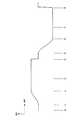
実質的な過渡電流の発生を避けるために、本実施態様は、図2に示すような電位波形を電気化学的セルに印加する。波形は、一連のデジタル値を入力としてデジタル・アナログ変換器103に供給することによって生成してもよく、次いでデジタル・アナログ変換器がポテンシオスタット104を駆動する。適切なデジタル値は、マイクロコントローラ101によって実行済みの簡単なアルゴリズムによって計算できるか、又は事前に計算され、メモリに記憶することができる。 In order to avoid the occurrence of substantial transient current, this embodiment applies a potential waveform as shown in FIG. 2 to the electrochemical cell. The waveform may be generated by supplying a series of digital values as input to the digital to
電気化学的セルに印加される波形は二つの部分を有し、第一の部分(t0〜t4)では正の電位がセルに印加され、第二の部分(t4〜t8)では負の電位が印加される。この例では、第二の部分は、第一の部分と類似した構造だが、反対の極性及び異なる大きさを有する。しかし、第二の部分は、同じ極性及び大きさを有してもよいし、たとえばさらなる測定を提供することを必要としなければ、省いてもよい。 The waveform applied to the electrochemical cell has two parts, a positive potential applied to the cell in the first part (t0 to t4) and a negative potential in the second part (t4 to t8). Applied. In this example, the second part is similar in structure to the first part, but has opposite polarity and a different size. However, the second portion may have the same polarity and size, and may be omitted, for example, if it is not necessary to provide further measurements.
波形の双方の部分で、電圧が実質的に0に保持される初期遅延t0〜t1の後に、期間t1〜t2で、波形は所望の電圧+V1までランプアップする。この期間中の電圧は、正弦波曲線の一部(約半サイクル)に合致して過渡電流を最小限にするが、他の波形を適用してもよい。ランプアップ部の後に、セルに印加される電位が実質的に一定に保持されるプラトーt2〜t4がある。プラトーの後半では、時間t3〜t4の間で、セルを通る電流がサンプリングされる。サンプルの数及びデータ速度は、行われる固有の電気化学的測定に適合するように選択することができ、たとえば、約300Hzの速度で20個のサンプルを採取してもよい。測定中に電気化学的セルに印加される電位差、すなわちプラトー電位は、検出及び/又は測定される種に依存する。±2V(Ag/AgCl電極に対して測定された)の範囲の電位が適切である。In both parts of the waveform, after an initial delay t0~t1 the voltage is held at substantially 0, in the period t1 to t2, the waveform ramps up to a desired voltage + V1. The voltage during this period matches a portion of the sinusoidal curve (about half a cycle) to minimize transients, but other waveforms may be applied. After the ramp up, there are plateaus t2 to t4 where the potential applied to the cell is held substantially constant. In the second half of the plateau, the current through the cell is sampled between times t3 and t4. The number of samples and the data rate can be selected to suit the specific electrochemical measurements being made, for example, 20 samples may be taken at a rate of about 300 Hz. The potential difference applied to the electrochemical cell during the measurement, ie the plateau potential, depends on the species to be detected and / or measured. A potential in the range of ± 2 V (measured against an Ag / AgCl electrode) is appropriate.
上述したように、例の波形の立ち下がり部は、例の波形の立ち上がり部の相当する部分の反転であるランプアップ部t5〜t6及びプラトー部t6〜t8を有する。当然、他の実施態様では、波形の第二の部分は、第一の部分と同じ極性及び/又は異なる大きさを有してもよい。 As described above, the falling portion of the waveform of the example has ramp-up portions t5 to t6 and plateau portions t6 to t8 that are inversions of the corresponding portions of the rising portion of the waveform of the example. Of course, in other embodiments, the second portion of the corrugation may have the same polarity and / or a different size as the first portion.
ランプアップ部分中、最大傾きは、過渡電流をポテンシオスタットの増幅器にシンクすることができるレベルよりも低く維持するように決定される。たとえば、約50Vs-1の速度が適切である。これは、約100msで0から±0.5Vまでの上昇を提供することになる。電位が1ms未満で上昇するステップ電位は、600Vs-1の速度を生じさせることができる。During the ramp-up portion, the maximum slope is determined to keep the transient current below a level that can sink the potentiostat amplifier. For example, a speed of about 50 Vs-1 is appropriate. This will provide an increase from 0 to ± 0.5 V in about 100 ms. A step potential that rises in less than 1 ms can cause a speed of 600 Vs−1 .
プラトーの最後で、過渡現象がさらなる測定に影響するのではなく、弱いランプダウンも使用してもよい場合、特に、他の測定をすぐ後に実行する場合、電圧を望みどおり速やかにゼロに戻すことができる。 At the end of the plateau, if the transient does not affect further measurements and a weak ramp-down may also be used, especially if another measurement is performed immediately afterwards, the voltage is quickly returned to zero as desired. Can do.
ランプアップ部分の目的は、ポテンシオスタットの一部を形成するIE変換器の過負荷を防ぐことであるため、要求された電位変化の速度は、図3に示すような基本的なポテンシオスタット回路の考察から決定することができる。ポテンシオスタットへの変調入力が図の右手側に示され、増幅され、電気化学的セルの共通電極CEに印加される。電位計が参照電極REの電気化学的電位をバッファリングし、この電位を加算増幅器に戻して、対向電極の電位が参照電極に対して維持されるようにする。IE変換器は、作用電極から流れ出す電流iを電圧出力V=RB*i(RBは、本質的には演算増幅器電流フォロワ回路である、IE変換器のフィードバック抵抗器の値である)に変換する。 Since the purpose of the ramp-up portion is to prevent overloading of the IE converter that forms part of the potentiostat, the required rate of potential change is the basic potentiostat as shown in FIG. It can be determined from circuit considerations. The modulation input to the potentiostat is shown on the right hand side of the figure, amplified and applied to the common electrode CE of the electrochemical cell. An electrometer buffers the electrochemical potential of the reference electrode RE and returns this potential to the summing amplifier so that the potential of the counter electrode is maintained relative to the reference electrode. The IE converter converts the current i flowing out of the working electrode into a voltage output V = RB * i (RB is essentially the value of the feedback resistor of the IE converter, which is an operational amplifier current follower circuit). .
実際の回路では、演算増幅器の最大電圧出力は、電源電圧及び選択された演算増幅器の特性によって制限される。演算増幅器の電圧出力はその電源電圧を超えることができないということは言外に含まれている。 In practical circuits, the maximum voltage output of the operational amplifier is limited by the power supply voltage and the characteristics of the selected operational amplifier. It should be noted that the voltage output of the operational amplifier cannot exceed its power supply voltage.
IE変換器の電圧出力がV=RB*iによって求められるならば、電源電圧によって規定される、回路に入力することができるiの最大値がある。iがこの値を超える状況では、演算増幅器の電圧出力は電源電圧によって制限される。この出力はもはや電流iを表さない。また、負の入力に対する影響も考慮すべきである。通常の演算では、負の入力における電位はゼロであり、iと、RBを通過する電流との和である。過負荷状態では、RBを通過する電流は、iに釣り合うにはもはや不十分であり、この結果、負の入力における電位はもはやゼロには保持されず、3電極システムではCEの電位に向かって上昇し、又は2電極システムでは擬似参照電極とでシフトする。これは、ポテンシオスタットをして電位制御を失わせ、そのため、電気化学的セルはもはや所望の電位に保持されない。電気化学的セルを通過する電流は、IE変換器の飽和によって制限されるという結果になる。したがって、最大ランプアップ速度は、IE変換器の飽和を防ぐためにセットされるべきであり、それは事実上、過渡電流が、測定される最大電流よりも大きくてはならないことを意味する。 If the voltage output of the IE converter is determined by V = RB * i, there is a maximum value of i that can be input to the circuit, defined by the power supply voltage. In situations where i exceeds this value, the voltage output of the operational amplifier is limited by the power supply voltage. This output no longer represents the current i. Also, the effect on negative inputs should be considered. In normal operation, the potential at the negative input is zero and is the sum of i and the current through RB. In an overload condition, the current passing through RB is no longer sufficient to balance i, so that the potential at the negative input is no longer held at zero and towards the CE potential in a three-electrode system. Ascend or shift with the pseudo reference electrode in a two-electrode system. This causes the potentiostat to lose potential control so that the electrochemical cell is no longer held at the desired potential. The result is that the current passing through the electrochemical cell is limited by the saturation of the IE converter. Thus, the maximum ramp-up rate should be set to prevent saturation of the IE converter, which effectively means that the transient current must not be greater than the maximum current measured.
この条件は、電力を節約し、回路を縮小するために電源電圧が最小限である必要があるバッテリーを動力源とした計器の場合に特に当てはまる。 This condition is particularly true for batteries powered instruments where power supply voltage needs to be minimal to save power and reduce circuitry.
固有の実施態様に関して本発明を説明したが、本発明は、他の形態で具現化してもよい。たとえば、線形掃引、対数関数、シグモイド関数、双曲線、ロジスティック関数、ワイブル関数、ゴンペルツ成長モデル、ヒル関数、チャップマンモデルを含む他の関数を使用してランプアップを規定してもよい。この文献における極性は、IUPAC規則を使用して定義されるが、結果は、他の規則に容易に変換することができる。したがって、本発明の範囲は、前記説明ではなく請求の範囲によって決定される。 Although the invention has been described with reference to specific embodiments, the invention may be embodied in other forms. For example, other functions including linear sweep, logarithmic function, sigmoid function, hyperbola, logistic function, Weibull function, Gompertz growth model, Hill function, Chapman model may be used to define the ramp-up. The polarity in this document is defined using IUPAC rules, but the results can be easily converted to other rules. Accordingly, the scope of the invention is determined by the appended claims rather than the foregoing description.
Claims (21)
Translated fromJapanese前記プラトー期間中に、前記作用電極と対向電極との間を流れる電流を測定のためにサンプリングすること、
を含む電気化学的検出方法であって、
時変電位が、電位差を第三の所定の電位から第四の所定の電位まで増加する第二のランプアップ期間と、及び前記電位差が前記第四の所定の電位で実質的に一定に維持される第二のプラトー期間と、をさらに含み;方法が、前記第二のプラトー期間中に前記電流をサンプリングすることをさらに含む、電気化学的検出方法。A ramp-up period in which the potential difference increases from a first predetermined potential to a second predetermined potential between the working electrode and the reference electrode in electrical contact with the target solution; Applying a time-varying potential having a plateau period maintained substantially constant at a predetermined potential; andduring the plateau period, for measuring a current flowing between the working electrode and the counter electrode Sampling to
An electrochemical detection method comprising:
A time-varying potential is maintained substantially constant at a second ramp-up period in which the potential difference is increased from a third predetermined potential to a fourth predetermined potential, and the potential difference is at the fourth predetermined potential. A second plateau period; wherein the method further comprises sampling the current during the second plateau period .
線形掃引、
対数関数、
シグモイド関数、
双曲線、
ロジスティック関数、
ワイブル関数、
ゴンペルツ成長モデル、
ヒル関数、
チャップマンモデル
からなる群より選択される関数の一部をたどる、請求項1〜4のいずれか1項記載の方法。The potential difference during the ramp-up period is substantially
Linear sweep,
Logarithmic function,
Sigmoid function,
Hyperbola,
Logistic function,
Weibull function,
Gompertz growth model,
Hill function,
Follows a part of a function selected from the group consisting of Chapman model, any one method according to claim1-4.
ポテンシオスタットを制御して、電位差が第一の所定の電位から第二の所定の電位まで増加するランプアップ期間と、続いて、前記電位差が前記第二の所定の電位で実質的に一定に維持されるプラトー期間と、を有する時変電位を印加させ、及び前記プラトー期間中に、前記作用電極と対向電極との間を流れる電流をサンプリングするためのコントローラと
を含む電気化学的検出装置であって、
コントローラがさらに、時変電位が、電位差が第三の所定の電位から第四の所定の電位まで増加する第二のランプアップ期間及び前記電位差が前記第四の所定の電位で実質的に一定に維持される第二のプラトー期間をさらに含むようにポテンシオスタットを制御し;及び前記第二のプラトー期間中に前記電流をサンプリングするように適合されている、電気化学的検出装置。A potentiostat for applying a potential between a working electrode and a counter electrode in electrical contact with the target solution and sampling the current flowing between the electrodes;
Controlling the potentiostat, a ramp-up period in which the potential difference increases from the first predetermined potential to the second predetermined potential, and then the potential difference is substantially constant at the second predetermined potential. to apply a substation position when it has a plateau period maintained, the, andduring the plateauperiod, electrochemical detection apparatus including a controller for sampling the current flowing between the working electrode and the counter electrodeThere,
The controller further includes a time-varying potential, a second ramp-up period in which the potential difference increases from a third predetermined potential to a fourth predetermined potential, and the potential difference is substantially constant at the fourth predetermined potential. An electrochemical detection device adapted to control the potentiostat to further include a maintained second plateau period; and to sample the current during the second plateau period .
線形掃引、
対数関数、
シグモイド関数、
双曲線、
ロジスティック関数、
ワイブル関数、
ゴンペルツ成長モデル、
ヒル関数、
チャップマンモデル
からなる群より選択される関数の一部をたどる、請求項11〜13のいずれか1項記載の装置。The potential difference during the ramp-up period is substantially
Linear sweep,
Logarithmic function,
Sigmoid function,
Hyperbola,
Logistic function,
Weibull function,
Gompertz growth model,
Hill function,
The apparatus according to any one of claims11 to13 , wherein the apparatus traces a part of a function selected from the group consisting of Chapman models.
Applications Claiming Priority (3)
| Application Number | Priority Date | Filing Date | Title |
|---|---|---|---|
| GB0418345AGB2417323A (en) | 2004-08-17 | 2004-08-17 | A method of operating an electrochemical sensor by applying a time variable potential between the electrodes. |
| GB0418345.5 | 2004-08-17 | ||
| PCT/GB2005/003054WO2006030170A1 (en) | 2004-08-17 | 2005-08-03 | Electrochemical sensor |
Publications (3)
| Publication Number | Publication Date |
|---|---|
| JP2008510157A JP2008510157A (en) | 2008-04-03 |
| JP2008510157A5 JP2008510157A5 (en) | 2008-05-29 |
| JP4819052B2true JP4819052B2 (en) | 2011-11-16 |
Family
ID=33042199
Family Applications (1)
| Application Number | Title | Priority Date | Filing Date |
|---|---|---|---|
| JP2007526558AExpired - LifetimeJP4819052B2 (en) | 2004-08-17 | 2005-08-03 | Electrochemical sensor |
Country Status (12)
| Country | Link |
|---|---|
| US (1) | US7545148B2 (en) |
| EP (1) | EP1782054B1 (en) |
| JP (1) | JP4819052B2 (en) |
| CN (1) | CN101002086B (en) |
| AT (1) | ATE472727T1 (en) |
| CA (1) | CA2577477C (en) |
| DE (1) | DE602005022080D1 (en) |
| ES (1) | ES2345938T3 (en) |
| GB (1) | GB2417323A (en) |
| MX (1) | MX2007001883A (en) |
| PL (1) | PL1782054T3 (en) |
| WO (1) | WO2006030170A1 (en) |
Cited By (1)
| Publication number | Priority date | Publication date | Assignee | Title |
|---|---|---|---|---|
| KR101333410B1 (en)* | 2011-11-01 | 2013-11-28 | 명지대학교 산학협력단 | Multiple potentiostat circuit and detection system using the same |
Families Citing this family (15)
| Publication number | Priority date | Publication date | Assignee | Title |
|---|---|---|---|---|
| US7796038B2 (en)* | 2006-06-12 | 2010-09-14 | Intelleflex Corporation | RFID sensor tag with manual modes and functions |
| GB0711780D0 (en) | 2007-06-18 | 2007-07-25 | Oxford Biosensors Ltd | Electrochemical data rejection methodology |
| GB0715036D0 (en)* | 2007-08-02 | 2007-09-12 | Oxford Biosensors Ltd | Shoulder elimination |
| GB0814238D0 (en)* | 2008-08-04 | 2008-09-10 | Oxford Biosensors Ltd | Enhancement of electrochemical response |
| EP2496936B1 (en)* | 2009-10-16 | 2018-02-21 | Microchips Biotech, Inc. | Multi-channel potentiostat for biosensor arrays and method of operation |
| WO2012084152A1 (en)* | 2010-12-20 | 2012-06-28 | Roche Diagnostics Gmbh | Controlled slew rate transition for electrochemical analysis |
| GR1008045B (en)* | 2012-05-22 | 2013-11-25 | ΜΙΚΡΟ-ΣΥΣΤΗΜΑΤΑ ΜΙΚΡΟ-ΡΟΗΣ ΓΙΑ ΓΕΝΕΤΙΚΟΥΣ ΕΛΕΓΧΟΥΣ ΚΑΙ ΜΟΡΙΑΚΗ ΔΙΑΓΝΩΣΤΙΚΗ ΕΠΕ με δ.τ. "Micro2Gen", | Parameterisable calibrated circuit for parallel measurements of an array of electrochemical sensors under continuous polarosation in real time |
| KR101732300B1 (en) | 2013-03-15 | 2017-05-02 | 에프. 호프만-라 로슈 아게 | Methods of failsafing electrochemical measurements of an analyte as well as devices, apparatuses and systems incorporating the same |
| CN105247356B (en) | 2013-03-15 | 2017-11-07 | 豪夫迈·罗氏有限公司 | Methods of using information from recovery pulses in electrochemical analyte measurements and devices, devices and systems incorporating said methods |
| CA2949906C (en) | 2013-03-15 | 2019-04-02 | F. Hoffmann-La Roche Ag | Methods of scaling data used to construct biosensor algorithms as well as devices, apparatuses and systems incorporating the same |
| KR101743382B1 (en) | 2013-03-15 | 2017-06-02 | 에프. 호프만-라 로슈 아게 | Methods of detecting high antioxidant levels during electrochemical measurements and failsafing an analyte concentration therefrom as well as devices, apparatuses and systems incorporting the same |
| EP3216076B1 (en) | 2014-11-03 | 2024-03-06 | F. Hoffmann-La Roche AG | Method of using electrochemical test elements having multiple electrode arrangements |
| WO2018067235A1 (en) | 2016-10-05 | 2018-04-12 | Roche Diabetes Care, Inc. | Detection reagents and electrode arrangements for multi-analyte diagnostic test elements, as well as methods of using the same |
| WO2018080637A1 (en) | 2016-10-24 | 2018-05-03 | Roche Diabetes Care, Inc. | Methods of correcting for uncompensated resistances in the conductive elements of biosensors, as well as devices and systems |
| US20240353362A1 (en)* | 2021-08-23 | 2024-10-24 | King Abdullah University Of Science And Technology | Small-sized, reconfigurable, multi-measurement potentiostat circuitry and method |
Citations (3)
| Publication number | Priority date | Publication date | Assignee | Title |
|---|---|---|---|---|
| JPH11183438A (en)* | 1997-12-19 | 1999-07-09 | Nec Corp | Application method for potential of biosensor |
| JP2000162176A (en)* | 1998-09-22 | 2000-06-16 | Omron Corp | Measuring method and measuring device using biosensor |
| JP2002189015A (en)* | 2000-12-20 | 2002-07-05 | Sankyo Co Ltd | Reaction-current measuring method by enzyme electrode |
Family Cites Families (11)
| Publication number | Priority date | Publication date | Assignee | Title |
|---|---|---|---|---|
| SU399775A1 (en)* | 1971-07-21 | 1973-10-03 | И. Е. Брыксин, Р. М. Ф. Салихджанова , И. Белицкий Всесоюзный научно исследовательский институт автоматизации черной металлургии | VARIABLE WAY OF POLAROGRAPHIC ANALYSIS |
| GB1448367A (en)* | 1972-11-09 | 1976-09-08 | Energy Secretary Of State For | Electrochemical cells |
| US4059406A (en)* | 1976-07-12 | 1977-11-22 | E D T Supplies Limited | Electrochemical detector system |
| US4340458A (en)* | 1980-06-02 | 1982-07-20 | Joslin Diabetes Center, Inc. | Glucose sensor |
| US4897162A (en)* | 1986-11-14 | 1990-01-30 | The Cleveland Clinic Foundation | Pulse voltammetry |
| DE4030873C2 (en)* | 1990-09-29 | 2000-05-04 | Conducta Endress & Hauser | Method for determining the concentration of electrochemically convertible gases |
| US5980708A (en)* | 1997-02-12 | 1999-11-09 | Champagne; Gilles Y. | High sensitivity multiple waveform voltammetric instrument |
| US6558529B1 (en)* | 2000-02-07 | 2003-05-06 | Steris Inc. | Electrochemical sensor for the specific detection of peroxyacetic acid in aqueous solutions using pulse amperometric methods |
| US6572745B2 (en)* | 2001-03-23 | 2003-06-03 | Virotek, L.L.C. | Electrochemical sensor and method thereof |
| JP2005510712A (en)* | 2001-11-26 | 2005-04-21 | イスケミア・テクノロジーズ・インコーポレーテッド | Electrochemical detection of ischemia |
| US20030201191A1 (en)* | 2002-04-29 | 2003-10-30 | Applied Materials, Inc. | Electrochemical method for direct organic additives analysis in copper baths |
- 2004
- 2004-08-17GBGB0418345Apatent/GB2417323A/ennot_activeWithdrawn
- 2005
- 2005-08-03CACA2577477Apatent/CA2577477C/ennot_activeExpired - Lifetime
- 2005-08-03PLPL05768051Tpatent/PL1782054T3/enunknown
- 2005-08-03MXMX2007001883Apatent/MX2007001883A/enactiveIP Right Grant
- 2005-08-03CNCN2005800273578Apatent/CN101002086B/ennot_activeExpired - Lifetime
- 2005-08-03ESES05768051Tpatent/ES2345938T3/ennot_activeExpired - Lifetime
- 2005-08-03JPJP2007526558Apatent/JP4819052B2/ennot_activeExpired - Lifetime
- 2005-08-03USUS11/660,255patent/US7545148B2/enactiveActive
- 2005-08-03WOPCT/GB2005/003054patent/WO2006030170A1/enactiveApplication Filing
- 2005-08-03ATAT05768051Tpatent/ATE472727T1/enactive
- 2005-08-03EPEP05768051Apatent/EP1782054B1/ennot_activeExpired - Lifetime
- 2005-08-03DEDE602005022080Tpatent/DE602005022080D1/ennot_activeExpired - Lifetime
Patent Citations (3)
| Publication number | Priority date | Publication date | Assignee | Title |
|---|---|---|---|---|
| JPH11183438A (en)* | 1997-12-19 | 1999-07-09 | Nec Corp | Application method for potential of biosensor |
| JP2000162176A (en)* | 1998-09-22 | 2000-06-16 | Omron Corp | Measuring method and measuring device using biosensor |
| JP2002189015A (en)* | 2000-12-20 | 2002-07-05 | Sankyo Co Ltd | Reaction-current measuring method by enzyme electrode |
Cited By (1)
| Publication number | Priority date | Publication date | Assignee | Title |
|---|---|---|---|---|
| KR101333410B1 (en)* | 2011-11-01 | 2013-11-28 | 명지대학교 산학협력단 | Multiple potentiostat circuit and detection system using the same |
Also Published As
| Publication number | Publication date |
|---|---|
| US7545148B2 (en) | 2009-06-09 |
| CA2577477C (en) | 2012-12-04 |
| US20070285099A1 (en) | 2007-12-13 |
| EP1782054B1 (en) | 2010-06-30 |
| CN101002086A (en) | 2007-07-18 |
| PL1782054T3 (en) | 2011-12-30 |
| GB2417323A (en) | 2006-02-22 |
| ES2345938T3 (en) | 2010-10-06 |
| ATE472727T1 (en) | 2010-07-15 |
| CN101002086B (en) | 2010-11-10 |
| JP2008510157A (en) | 2008-04-03 |
| CA2577477A1 (en) | 2006-03-23 |
| EP1782054A1 (en) | 2007-05-09 |
| WO2006030170A1 (en) | 2006-03-23 |
| MX2007001883A (en) | 2007-04-24 |
| DE602005022080D1 (en) | 2010-08-12 |
| GB0418345D0 (en) | 2004-09-22 |
Similar Documents
| Publication | Publication Date | Title |
|---|---|---|
| JP4819052B2 (en) | Electrochemical sensor | |
| JP4217211B2 (en) | Sample analysis method and sample analyzer | |
| CN212622387U (en) | Portable electrochemical workstation circuit | |
| JP2010169527A (en) | Method and apparatus for measuring frequency characteristic of internal impedance of fuel cell | |
| AU2017214406A1 (en) | Sensor interrogation with fast recovery | |
| CN102323474A (en) | Digital readout ampere meter for detecting pulse current | |
| CN106483184A (en) | Heavy metal analysis device and method based on graphene sensor | |
| Huang et al. | Design of a portable mini potentiostat for electrochemical biosensors | |
| Ning et al. | A portable potentiostat for three-electrode electrochemical sensor | |
| US11536691B2 (en) | Portable instrument for field ready electrochemical experimentation | |
| US20190380631A1 (en) | Methods and Systems for Low Power/Low Cost Hematocrit Measurement for Blood Glucose Meter | |
| Huang | Design of a portable potentiostat with dual-microprocessors for electrochemical biosensors | |
| JP6396321B2 (en) | Conductivity measurement with wide dynamic range of water | |
| US5530361A (en) | Method and apparatus for measuring the state of charge of an electrochemical cell pulse producing a high discharge current | |
| US8282797B2 (en) | Electrode preconditioning | |
| US7467048B2 (en) | Electrochemical sensor | |
| CN202383192U (en) | Digital display ammeter capable of detecting pulse current | |
| US20050167266A1 (en) | ECMP system | |
| Huang et al. | Design of a potentiostat with standalone signal generator for vanillylmandelic acid biosensors | |
| Huang | Design and Implementation of Potentiostat with Standalone Signal Generator for Vanillylmandelic Acid Biosensors. | |
| CN109991281B (en) | Detection device and detection method | |
| RU12253U1 (en) | CONDUCTOMETER FOR DETERMINING SPECIFIC ELECTRICAL CONDUCTIVITY OF AQUEOUS SOLUTIONS | |
| KR20140001420A (en) | Appartus for sensing pesticide and appartus for detecting pesticide residu | |
| Stevic et al. | Electrochemical processec modeling and sensing upon dirac potentionstatic excitation | |
| TH14687C3 (en) | Electrochemical analyzer with programmable system on a single chip |
Legal Events
| Date | Code | Title | Description |
|---|---|---|---|
| A521 | Request for written amendment filed | Free format text:JAPANESE INTERMEDIATE CODE: A523 Effective date:20080403 | |
| A621 | Written request for application examination | Free format text:JAPANESE INTERMEDIATE CODE: A621 Effective date:20080403 | |
| A977 | Report on retrieval | Free format text:JAPANESE INTERMEDIATE CODE: A971007 Effective date:20100826 | |
| A131 | Notification of reasons for refusal | Free format text:JAPANESE INTERMEDIATE CODE: A131 Effective date:20110301 | |
| A601 | Written request for extension of time | Free format text:JAPANESE INTERMEDIATE CODE: A601 Effective date:20110519 | |
| A602 | Written permission of extension of time | Free format text:JAPANESE INTERMEDIATE CODE: A602 Effective date:20110526 | |
| A711 | Notification of change in applicant | Free format text:JAPANESE INTERMEDIATE CODE: A711 Effective date:20110609 | |
| A521 | Request for written amendment filed | Free format text:JAPANESE INTERMEDIATE CODE: A523 Effective date:20110616 | |
| A521 | Request for written amendment filed | Free format text:JAPANESE INTERMEDIATE CODE: A821 Effective date:20110609 | |
| TRDD | Decision of grant or rejection written | ||
| A01 | Written decision to grant a patent or to grant a registration (utility model) | Free format text:JAPANESE INTERMEDIATE CODE: A01 Effective date:20110802 | |
| A01 | Written decision to grant a patent or to grant a registration (utility model) | Free format text:JAPANESE INTERMEDIATE CODE: A01 | |
| A61 | First payment of annual fees (during grant procedure) | Free format text:JAPANESE INTERMEDIATE CODE: A61 Effective date:20110831 | |
| FPAY | Renewal fee payment (event date is renewal date of database) | Free format text:PAYMENT UNTIL: 20140909 Year of fee payment:3 | |
| R150 | Certificate of patent or registration of utility model | Ref document number:4819052 Country of ref document:JP Free format text:JAPANESE INTERMEDIATE CODE: R150 Free format text:JAPANESE INTERMEDIATE CODE: R150 | |
| R250 | Receipt of annual fees | Free format text:JAPANESE INTERMEDIATE CODE: R250 | |
| R250 | Receipt of annual fees | Free format text:JAPANESE INTERMEDIATE CODE: R250 | |
| R250 | Receipt of annual fees | Free format text:JAPANESE INTERMEDIATE CODE: R250 | |
| R250 | Receipt of annual fees | Free format text:JAPANESE INTERMEDIATE CODE: R250 | |
| R250 | Receipt of annual fees | Free format text:JAPANESE INTERMEDIATE CODE: R250 | |
| R250 | Receipt of annual fees | Free format text:JAPANESE INTERMEDIATE CODE: R250 | |
| R250 | Receipt of annual fees | Free format text:JAPANESE INTERMEDIATE CODE: R250 | |
| R250 | Receipt of annual fees | Free format text:JAPANESE INTERMEDIATE CODE: R250 | |
| R250 | Receipt of annual fees | Free format text:JAPANESE INTERMEDIATE CODE: R250 | |
| R250 | Receipt of annual fees | Free format text:JAPANESE INTERMEDIATE CODE: R250 | |
| R250 | Receipt of annual fees | Free format text:JAPANESE INTERMEDIATE CODE: R250 |