JP4818740B2 - Electronic equipment - Google Patents
Electronic equipmentDownload PDFInfo
- Publication number
- JP4818740B2 JP4818740B2JP2006015511AJP2006015511AJP4818740B2JP 4818740 B2JP4818740 B2JP 4818740B2JP 2006015511 AJP2006015511 AJP 2006015511AJP 2006015511 AJP2006015511 AJP 2006015511AJP 4818740 B2JP4818740 B2JP 4818740B2
- Authority
- JP
- Japan
- Prior art keywords
- power
- load
- power consumption
- electronic device
- image forming
- Prior art date
- Legal status (The legal status is an assumption and is not a legal conclusion. Google has not performed a legal analysis and makes no representation as to the accuracy of the status listed.)
- Active
Links
Images


Landscapes
- Fixing For Electrophotography (AREA)
- Control Or Security For Electrophotography (AREA)
- Supply And Distribution Of Alternating Current (AREA)
Description
Translated fromJapanese本発明は、電力源からブレーカを介して配線されているコンセント等に接続して使用される画像形成装置等の電子装置に関する。 The present invention relates to an electronic apparatus such as an image forming apparatus that is used by being connected from an electric power source to an outlet or the like wired through a breaker.
従来、画像形成装置等の電子装置は、一般に、商用電源等の電力源からブレーカを介して配線されるコンセント等に接続して使用される。そこで、このコンセント等からブレーカの許容値以上の電流が出力された場合、即ち、このコンセント等に接続された電気機器等が、ブレーカの許容値以上の電力を消費した場合に、火災等の災害防止の観点から、このコンセント等や電力源、或いは、この電力源からコンセント等への配線に用いられている電線やケーブル等を保護するために、ブレーカによりコンセント等への電力供給が遮断される。 2. Description of the Related Art Conventionally, an electronic apparatus such as an image forming apparatus is generally used by connecting to an outlet or the like wired from a power source such as a commercial power source through a breaker. Therefore, when a current exceeding the allowable value of the breaker is output from this outlet, that is, when electrical equipment connected to this outlet consumes more power than the allowable value of the breaker, a disaster such as a fire From the viewpoint of prevention, the breaker interrupts the power supply to the outlet, etc. to protect the outlet, the power source, or the wires and cables used for wiring from the power source to the outlet, etc. .
そこで、電子装置をこのようなコンセントに接続して使用する場合に、電子装置の最大消費電力が、ブレーカの最大許容電力以下であり、且つ、このコンセントに接続して使用されるのが、当該電子装置だけである場合は、電力供給が遮断されることなく使用することができ、問題はない。 Therefore, when the electronic device is used connected to such an outlet, the maximum power consumption of the electronic device is equal to or less than the maximum allowable power of the breaker, and the electronic device is used connected to this outlet. When only an electronic device is used, it can be used without interruption of power supply, and there is no problem.
しかし、同一のブレーカに接続されたコンセントに、他の電気機器等が接続されて使用されていることもある。或いは、使用の途中で、他の電気機器等が接続されて使用が開始されることもある。このような場合に、同一のブレーカに接続されたコンセントに接続されている負荷の合計消費電力が、ブレーカの最大許容電力を超えると、使用の途中で電力供給が遮断される事態となる。 However, other electrical devices or the like may be connected to an outlet connected to the same breaker. Alternatively, in the middle of use, other electric devices or the like may be connected to start use. In such a case, if the total power consumption of the load connected to the outlet connected to the same breaker exceeds the maximum allowable power of the breaker, the power supply is interrupted during use.
そうすると、使用の途中で電力供給が遮断された画像形成装置等の電子装置を、復旧させる必要が生じるが、画像形成装置等の最近の電子装置は、構成が複雑であることから、復旧に手間がかかっていた。 Then, it is necessary to restore an electronic device such as an image forming apparatus whose power supply is cut off during use. However, recent electronic devices such as an image forming apparatus have a complicated configuration, and thus it is troublesome to restore. It was over.
そこで、このような事態が発生しないように、同一の電力源に複数の電子装置を接続して使用する場合に、合計消費電力がブレーカの最大許容電力を超えないようにする仕組みが考案されている(例えば、特許文献1参照)。
上記の特許文献1に記載の方法は、同一の電力源に接続される複数の各電子装置が使用中に、使用中信号を電源線に発信し、これを受信回路で受信した他の電子装置が、自らの稼動を抑制しようとする仕組みである。そのため、この仕組みを有効に機能させるためには、同一の電力源に接続される複数の電子装置全てに、使用中信号の発信回路や受信回路を備える必要があり、全ての電子装置に上記のような専用回路を設けることは、現実的ではないことから、実際に上記の仕組みを用いることは困難であった。 In the method described in
そのため、電力源からブレーカを介して配線されるコンセント等に接続して使用される電子装置に対して、電子装置が、電力供給の遮断を回避することが単独で可能な方策が求められていた。 Therefore, for an electronic device that is used by connecting to an outlet or the like wired from a power source through a breaker, a measure that enables the electronic device to avoid interruption of power supply has been demanded. .
そこで、この発明は、このような要望に対処するためになされたものであって、電力源からブレーカを介して配線されるコンセント等に接続して使用される際に、電力供給の遮断を回避することが、単独で可能な電子装置を提供しようとするものである。 Therefore, the present invention has been made to cope with such a demand, and avoids interruption of power supply when used by connecting to a power outlet or the like wired from a power source through a breaker. It is intended to provide an electronic device capable of being alone.
本発明の電子装置は、起電力及び内部抵抗を有する電力源から電力が供給される電力源出力端子に接続して使用されると共に、値が既知である基準負荷を少なくとも備えた電子装置である。上記の電力源出力端子は、例えば、上述したコンセントがこれに該当する。この電子装置は、電圧測定記憶手段と消費電力演算手段とを備えることを特徴としている。 The electronic device of the present invention is an electronic device that is used by being connected to a power source output terminal to which power is supplied from a power source having an electromotive force and an internal resistance, and at least a reference load having a known value. . For example, the above-described outlet corresponds to the power source output terminal. This electronic apparatus is characterized by comprising voltage measurement storage means and power consumption calculation means.
上記の電圧測定記憶手段は、電力源に対して無負荷状態となるようにして、電子装置が電力源出力端子に接続された際に、電力源出力端子の電圧である無負荷電圧VOを、予め、測定して記憶する。又、電力源に対する負荷が基準負荷のみとなるようにして、電子装置が電力源出力端子に接続された際に、電力源出力端子の電圧である基準負荷電圧VCを、予め、測定して記憶する。そして、電子装置が使用のため、他の電力負荷が接続されている電力源出力端子に並列に接続された際に、該電力源出力端子における出力電圧VUを、測定して記憶する機能を備えている。The voltage measurement storage means is configured such that when the electronic device is connected to the power source output terminal so as to be in a no-load state with respect to the power source, the no-load voltage VO that is the voltage of the power source output terminal is obtained. Measure and store in advance. Further, when the electronic device is connected to the power source output terminal so that the load on the power source is only the reference load, the reference load voltage VC that is the voltage of the power source output terminal is measured in advance. Remember. A function of measuring and storing the output voltage VU at the power source output terminal when the electronic device is connected in parallel to the power source output terminal to which another power load is connected for use. I have.
消費電力演算手段は、予め、上記の基準負荷の値ZCを記憶していると共に、該基準負荷の値ZC、上記の無負荷電圧VO、上記の基準負荷電圧VC、及び、上記の出力電圧VUを基にして、電子装置が使用のために電力源出力端子に接続されているときの、電力源に対する総使用消費電力PUを演算する機能を備えている。The power consumption calculation means stores the reference load value ZC in advance, the reference load value ZC , the no-load voltage VO , the reference load voltage VC , and the above output voltage based on VU of the electronic device when connected to a power source output terminal for use, has a function of calculating the total usage consumed power PU to the power source.
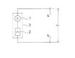
上記の消費電力演算手段は、次のようにして総使用消費電力PUを演算する。上記の電力源の起電力をE、内部抵抗の値をZOとすると、電圧測定記憶手段により、無負荷電圧VOが測定されて記憶される。図1は、この無負荷電圧VOの測定時の状態を模式的に示した回路図である。この無負荷電圧VOの測定及び記憶としては、起電力1がE、内部抵抗2の値がZOの電力源3に対して無負荷状態となるようにして電子装置が電力源出力端子4に接続された際に、電力源出力端子4の電圧である無負荷電圧VOが測定されて記憶される。この場合、図1から、下記の式が成立する。
VO=E ・・・・・・・・・・・・・・・・・・・(1)The power consumption calculation means calculates the total power consumption PU as follows. When the electromotive force of the power source is E and the value of the internal resistance is ZO , the no-load voltage VO is measured and stored by the voltage measurement storage means. FIG. 1 is a circuit diagram schematically showing a state during measurement of the no-load voltage VO. For measurement and storage of the no-load voltage VO , the electronic device is placed in the no-load state with respect to the
VO = E (1)
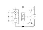
次に、電圧測定記憶手段により、基準負荷電圧VCが測定されて記憶される。図2は、この基準負荷電圧VCの測定時の状態を模式的に示した回路図である。この基準負荷電圧VCの測定及び記憶としては、起電力1がE、内部抵抗2の値がZOの電力源3に対する負荷が、値がZCの基準負荷のみとなるようにして、電子装置が電力源出力端子4に接続された際に、電力源出力端子4の電圧である基準負荷電圧VCが測定されて記憶される。この場合、図2から、下記の式が成立する。
VC=(E・ZC)/(ZO+ZC) ・・・・・・・・・・(2)
又、(1)、(2)から、下記の式が成立する。
ZO=ZC(VO−VC)/VC ・・・・・・・・・・・・(3)Next, the reference load voltage VC is measured and stored by the voltage measurement storage means. FIG. 2 is a circuit diagram schematically showing a state at the time of measuring the reference load voltage VC. The measurement and storage of the reference load voltage VC is performed by making the load on the
VC = (E · ZC ) / (ZO + ZC ) (2)
From (1) and (2), the following equation is established.
ZO = ZC (VO −VC ) / VC (3)
次に、電子装置の使用時に、電圧測定記憶手段により、出力電圧VUが測定されて記憶される。図3は、この出力電圧VUの測定時の状態を模式的に示した回路図である。この出力電圧VUの測定及び記憶としては、電子装置が使用のため、起電力1がE、内部抵抗2の値がZOの電力源3に対する他の電力負荷が接続されている電力源出力端子4に並列に接続された際に、該電力源出力端子4における出力電圧VUが測定されて記憶される。尚、図3の回路において、ZUは、上記の電力源3に対する全負荷の値である。値がZUであるこの負荷には、負荷としての上記の電子装置も含まれる。この場合、図3から、下記の式が成立する。
VU=(E・ZU)/(ZO+ZU) ・・・・・・・・・・・(4)
PU=VU2/ZU ・・・・・・・・・・・・・・・・・(5)
又、(1)、(3)、(4)から、下記の式が成立する。
ZU=ZC・VU(VO−VC)/{VC(VO−VU)} ・・・・(6)
又、(5)、(6)から、下記の式が成立する。
PU=VC・VU(VO−VU)/{ZC(VO−VC)} ・・・・(7)
上記の(7)式の右辺は、全て既知の値で構成されているので、(7)式から、総使用消費電力PUを求めることができる。このようにして、電子装置が使用のために電力源出力端子4に接続されているときの、電力源3に対する総使用消費電力PUが、消費電力演算手段により演算される。Next, when the electronic device is used, the output voltage VU is measured and stored by the voltage measurement storage means. FIG. 3 is a circuit diagram schematically showing the state when the output voltage VU is measured. As the measurement and storage of the output voltage VU, the power source output to which the other power load is connected to the
VU = (E · ZU ) / (ZO + ZU ) (4)
PU = VU2 / ZU (5)
From (1), (3), and (4), the following equation is established.
ZU = ZC · VU (VO −VC ) / {VC (VO −VU )} (6)
From (5) and (6), the following equation is established.
PU = VC · VU (VO −VU ) / {ZC (VO −VC )} (7)
Since the right side of the above expression (7) is composed of known values, the total used power consumption PU can be obtained from the expression (7). In this way, the total power consumption PU for the
上記の電子装置によれば、この電子装置を使用するために、起電力及び内部抵抗を有する電力源から電力が供給される電力源出力端子にこの電子装置を接続した際における総使用消費電力PUが演算される。この総使用消費電力PUは、後述するように、この電子装置単独で、この電子装置に対する消費電力の管理及び制御に役立てることができる。According to the electronic device, in order to use the electronic device, the total power consumption P when the electronic device is connected to a power source output terminal to which power is supplied from a power source having an electromotive force and an internal resistance.U is calculated. As will be described later, the total power consumption PU can be used for the management and control of power consumption of the electronic device by itself.
上記の電力源出力端子が、値の既知である最大許容電流IMのブレーカを介して、電力源から電力を供給されているような電力源出力端子であると、この電力源出力端子に上記の電子装置が接続される場合、上記の電子装置は、次のような機能を備えるのが好ましい。即ち、上記の消費電力演算手段に、予め、上記のブレーカの最大許容電流IMを記憶させておく。そして、この消費電力演算手段により、上記の最大許容電流IM、基準負荷の値ZC、無負荷電圧VO、及び、基準負荷電圧VCを基にして、ブレーカによる電力遮断を伴わずに使用可能な最大許容消費電力PMが演算されるようにするのである。When the power source output terminal is a power source output terminal that is supplied with power from the power source via the breaker having the maximum allowable current IM whose value is known, the power source output terminal is connected to the power source output terminal. When the electronic device is connected, the electronic device preferably has the following functions. That is, the maximum allowable current IM of the breaker is stored in advance in the power consumption calculation means. Then, the power consumption calculation means is used without the power interruption by the breaker on the basis of the maximum allowable current IM , the reference load value ZC , the no-load voltage VO , and the reference load voltage VC. The maximum allowable power consumption PM that can be used is calculated.
上記の消費電力演算手段は、次のようにして最大許容消費電力PMを演算する。図4は、上記の電子装置が、値の既知である最大許容電流IMのブレーカ5を介して、起電力1がE、内部抵抗2の値がZOの電力源3から電力を供給される電力源出力端子4に接続されていると共に、電力源3がブレーカ5の最大許容電流IMを流している状態を模式的に表した回路図である。尚、図4の回路において、ZMは、図4の回路にブレーカ5の最大許容電流IMが流れている状態における、上記の電力源3に対する全負荷の値である。値がZMであるこの負荷には、負荷としての上記の電子装置も含まれる。この図4から、下記の式が成立する。
IM=E/(ZO+ZM) ・・・・・・・・・・・・・・(8)
PM=IM2・ZM ・・・・・・・・・・・・・・・・(9)
又、(1)、(3)、(8)から、下記の式が成立する。
ZM=VO/IM−ZC(VO−VC)/VC ・・・・・・・・(10)
又、(9)、(10)から、下記の式が成立する。
PM=IM・VO−IM2・ZC(VO−VC)/VC ・・・・(11)
上記の(11)式の右辺は、全て既知の値で構成されているので、(11)式から、最大許容消費電力PMを求めることができる。このようにして、最大許容消費電力PMが、消費電力演算手段により演算される。Consumption computing means described above, calculates the maximum allowable power dissipation PM in the following manner. FIG. 4 shows that the above-mentioned electronic device is supplied with power from a
IM = E / (ZO + ZM ) (8)
PM = IM2 · ZM (9)
From (1), (3), and (8), the following equation is established.
ZM = VO / IM −ZC (VO −VC ) / VC (10)
From (9) and (10), the following equation is established.
PM = IM · VO −IM2 · ZC (VO −VC ) / VC (11)
Right side of the equation (11), since all are composed of known value, from equation (11), it is possible to find the maximum allowable power dissipation PM. In this way, the maximum power dissipation PM is calculated by the power consumption calculation means.
上記の電子装置によれば、起電力及び内部抵抗を有する電力源から、値の既知である最大許容電流IMのブレーカを介して、電力が供給される電力源出力端子に、この電子装置を接続した場合に、上記の電力源に対するブレーカによる電力遮断を伴わずに使用可能な最大許容消費電力PMが演算される。この最大許容消費電力PMは、後述するように、この電子装置単独で、この電子装置に対する消費電力の管理及び制御に役立てることができる。According to the above electronic device, the electronic device is connected to the power source output terminal to which power is supplied from the power source having the electromotive force and the internal resistance via the breaker having the maximum allowable current IM whose value is known. When connected, the maximum allowable power consumption PM that can be used without power interruption by the breaker for the power source is calculated. The maximum allowable power dissipation PM, as described later, in the electronic device itself, can be useful in the management and control of power consumption for the electronic device.
ブレーカを介して、電力源から電力を供給される電力源出力端子に接続する上記の電子装置において、最大許容消費電力PMから総使用消費電力PUを減算して、増加可能消費電力PRを求める消費電力管理制御手段を備えるのが、好ましい。又、この消費電力管理制御手段は、上記の減算の結果、増加可能消費電力PRがマイナスとなると、警告を発生するようにしてもよい。更に、この消費電力管理制御手段は、上記の減算の結果、増加可能消費電力PRがマイナスとなると、電子装置の動作を停止するようにしてもよい。In the above electronic device connected to the power source output terminal supplied with power from the power source via the breaker, the total power consumption PU is subtracted from the maximum allowable power consumption PM to increase the power consumption PR that can be increased. It is preferable to provide power consumption management control means for obtaining Also, the power management control unit, the above result of the subtraction, the possible increase power PR is negative, it may be generated a warning. In addition, the power management control unit, the above result of the subtraction, the possible increase power PR is negative, may be to stop the operation of the electronic device.
このようにすることにより、上記の電子装置単独で、この電子装置に対する消費電力の的確な管理及び制御を行うことができる。 By doing so, it is possible to perform accurate management and control of power consumption for the electronic device by using the electronic device alone.
上記の電子装置において、次のようにするのが好ましい。即ち、上記の電子装置には、電圧測定記憶手段、消費電力演算手段、及び、消費電力管理制御手段以外に、単又は複数の内部負荷が備えられていると共に、消費電力管理制御手段に、予め、全ての内部負荷の内部負荷最大消費電力PCnを記憶させる。In the above electronic device, the following is preferable. That is, the electronic device includes a single or plural internal loads in addition to the voltage measurement storage unit, the power consumption calculation unit, and the power consumption management control unit. The maximum internal load power consumption PCn of all internal loads is stored.
そして、上記の消費電力管理制御手段が、内部負荷最大消費電力PCnと増加可能消費電力PRとを比較して、内部負荷最大消費電力PCnが増加可能消費電力PRを超えなければ、内部負荷への電力供給を許容するようにするのである。このようにすることにより、上記の電子装置単独で、この電子装置に対する消費電力の的確な管理及び制御を行うことができる。Then, the above-mentioned power management control unit compares the possible increase power PR and the internal load maximum power consumption PCn, if the internal load maximum power consumption PCn does not exceed an increase available power PR, The power supply to the internal load is allowed. By doing so, it is possible to perform accurate management and control of power consumption for the electronic device by using the electronic device alone.
又、上記の電子装置において、消費電力管理制御手段は、内部負荷最大消費電力PCnと増加可能消費電力PRとを比較して、内部負荷最大消費電力PCnが増加可能消費電力PRを超えと、警告を発生するようにしてもよい。このようにすることにより、上記の電子装置単独で、この電子装置に対する消費電力の的確な管理及び制御を行うことができる。In the above electronic device, power management control unit compares the possible increase power PR and the internal load maximum power consumption PCn, the possible power PR increases internal load maximum power consumption PCn A warning may be generated when the limit is exceeded. By doing so, it is possible to perform accurate management and control of power consumption for the electronic device by using the electronic device alone.
又、単又は複数の内部負荷を備える上記の電子装置において、上述した基準負荷として、上記の内部負荷のいずれかを用いるようにしてもよい。このようにするのは、上記の基準負荷として、電子装置の構成要素を使用することができ、電子装置の本来の機能に関係のない基準負荷を格別に備える必要がなくなるからである。 Further, in the above electronic device including one or a plurality of internal loads, any of the above internal loads may be used as the reference load described above. This is because a component of the electronic device can be used as the above-described reference load, and it is not necessary to provide a reference load that is not related to the original function of the electronic device.
又、この基準負荷として、内部負荷最大消費電力PCnが最も大きい内部負荷を用いるのが好ましい。このようにするのは、上記の基準負荷としては消費電力が大きい方が、消費電力の演算精度の観点で好ましいからである。Moreover, it is preferable to use an internal load having the largest internal load maximum power consumption PCn as the reference load. This is because, as the reference load, a larger power consumption is preferable from the viewpoint of calculation accuracy of power consumption.
又、上述した電子装置として、画像形成装置を形成することができる。この画像形成装置では、上記の基準負荷として、画像形成装置の定着機構に備えられた加熱ヒータを用いるようにしてもよい。或いは、上記の基準負荷として、画像形成装置のオプション装置を用いるようにしてもよい。上記のオプション装置とは、例えば、後処理装置や、大容量給紙カセット、複数ビン排紙トレイ等である。このようにするのは、画像形成装置の定着機構に備えられた加熱ヒータや上記のオプション装置は、画像形成装置の構成要素としては比較的消費電力が大きいからである。 In addition, an image forming apparatus can be formed as the electronic apparatus described above. In this image forming apparatus, a heater provided in a fixing mechanism of the image forming apparatus may be used as the reference load. Alternatively, an optional device of the image forming apparatus may be used as the reference load. Examples of the optional device include a post-processing device, a large-capacity paper feed cassette, and a multi-bin paper discharge tray. This is because the heater and the optional device provided in the fixing mechanism of the image forming apparatus consume relatively large power as a component of the image forming apparatus.
本発明の電子装置によれば、この電子装置は、この電子装置を使用するために起電力及び内部抵抗を有する電力源から電力が供給される電力源出力端子に、この電子装置を接続した際における総使用消費電力PUを演算することができる。この総使用消費電力PUは、この電子装置単独で、この電子装置に対する消費電力の管理及び制御に役立てることができる。According to the electronic device of the present invention, when the electronic device is connected to a power source output terminal to which power is supplied from a power source having an electromotive force and an internal resistance in order to use the electronic device, The total power consumption PU can be calculated. This total power consumption PU can be used for management and control of power consumption of the electronic device by itself.
又、起電力及び内部抵抗を有する電力源から、値の既知である最大許容電流IMのブレーカを介して、電力が供給される電力源出力端子にこの電子装置を接続した場合に、この電子装置に最大許容電流IMを記憶させることによって、上記の電力源に対するブレーカによる電力遮断を伴わずに使用可能な最大許容消費電力PMを演算することができる。この最大許容消費電力PMは、この電子装置単独で、この電子装置に対する消費電力の管理及び制御に役立てることができる。In addition, when this electronic device is connected to a power source output terminal to which power is supplied from a power source having an electromotive force and an internal resistance via a breaker having a known maximum allowable current IM , the electronic device By storing the maximum allowable current IM in the apparatus, it is possible to calculate the maximum allowable power consumption PM that can be used without power interruption by the breaker with respect to the power source. The maximum allowable power dissipation PM is in the electronic device itself, it can be useful in the management and control of power consumption for the electronic device.
この場合に、最大許容消費電力PMから総使用消費電力PUを減算して、増加可能消費電力PRを求めることができる。又、増加可能消費電力PRがゼロ又はマイナスとなると、警告を発生するようにすることができる。更に、増加可能消費電力PRがゼロ又はマイナスとなると、電子装置の動作を停止するようにすることができる。従って、本発明の電子装置単独で、この電子装置に対する消費電力の的確な管理及び制御を行うことができる。In this case, by subtracting the total used power PU from the maximum allowable power dissipation PM, it is possible to determine the possible increase power consumption PR. Also, the possible increase power PR is zero or negative, it may be adapted to generate an alarm. Furthermore, the possible increase power PR is zero or negative, it can be made to stop the operation of the electronic device. Therefore, it is possible to perform accurate management and control of power consumption for the electronic device by the electronic device alone of the present invention.
又、本発明の電子装置に、単又は複数の内部負荷が備えられている場合、予め、全ての内部負荷の内部負荷最大消費電力PCnを記憶させておくことによって、内部負荷最大消費電力PCnと増加可能消費電力PRとを比較して、内部負荷最大消費電力PCnが増加可能消費電力PRを超えなければ、内部負荷への電力供給を許容するようにすることができる。又、内部負荷最大消費電力PCnが増加可能消費電力PRを超えと、警告を発生するようにすることができる。従って、本発明の電子装置単独で、この電子装置に対する消費電力の的確な管理及び制御を行うことができる。When the electronic device of the present invention is provided with one or a plurality of internal loads, the internal load maximum power consumption PCn is stored in advance by storing the internal load maximum power consumption PCn of all the internal loads. by comparing the possible increasedCn power PR, if the internal load maximum power consumption PCn does not exceed an increase available power PR, it can be made to permit the power supply to the internal load. Further, it is possible to make the internal load maximum power consumption PCn is generated and exceed the possible increase power consumption PR, a warning. Therefore, it is possible to perform accurate management and control of power consumption for the electronic device by the electronic device alone of the present invention.
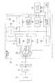
以下、本発明の実施の形態における画像形成装置について、図面を参照しながら詳しく説明する。本実施の形態における画像形成装置は、モノクロの文字や図形等を、スキャナで読取ると共に記録用紙に記録するモノクロ複写機である。図5は、本実施の形態における画像形成装置10の構成を示した構成図、図6は、この画像形成装置10の制御部の構成を示したブロック図である。この画像形成装置10は、電力源からブレーカを介して電力が供給される電源コンセントに接続して使用する際に、このブレーカによる電力遮断が生じないようにするために、この画像形成装置10の消費電力の管理及び制御を行うことを特徴としている。 Hereinafter, an image forming apparatus according to an embodiment of the present invention will be described in detail with reference to the drawings. The image forming apparatus according to the present embodiment is a monochrome copying machine that reads monochrome characters and graphics with a scanner and records them on a recording sheet. FIG. 5 is a block diagram showing the configuration of the
最初に、本実施の形態における画像形成装置の構成について説明する。図5において、上記の画像形成装置10は、モノクロスキャナ部31とモノクロ画像記録部32、及び、これらの制御を行う図5に図示されていない制御部33とで構成されている。 First, the configuration of the image forming apparatus in the present embodiment will be described. In FIG. 5, the
モノクロスキャナ部31は、原稿を搬送する原稿搬送部と、搬送された原稿に記載されている画像を読取る画像読取部で構成されている。 The
モノクロ画像記録部32は、モノクロ画像形成ユニット70、定着ユニット73、第1記録用紙収納トレイ41、第2記録用紙収納トレイ42、第3記録用紙収納トレイ43、第4記録用紙収納トレイ44、水平供給搬送路51、水平排出搬送路52、第1垂直搬送路53、第2垂直搬送路54、第3垂直搬送路55、水平帰還搬送路56、及び、排出収容トレイ57で構成されている。 The monochrome
モノクロ画像形成ユニット70には、感光体ドラム71と加圧ローラ72とが備えられており、モノクロスキャナ部6で読取られた画像が、この感光体ドラム71の表面にモノクロ画像として形成されると共に、この感光体ドラム71の表面に形成されたモノクロ画像が、記録用紙収納トレイ41,42,43,44のいずれかから、第1垂直搬送路53又は第2垂直搬送路54と水平供給搬送路51を経由して搬送される記録用紙Pに転写される。 The monochrome
又、定着ユニット73は、前述の定着機構に相当し、定着ローラ74と加圧ローラ75とで構成されており、記録用紙Pに転写された画像を定着する機能を有している。この定着ユニット73を構成する定着ローラ74の内部には、定着に必要な熱を発生する加熱ヒータ76が設けられている。この加熱ヒータ76は、前述の基準負荷として用いられ、その負荷としての値は、既知である。 The fixing
上記の定着ユニット73で定着された記録用紙Pは、水平排出搬送路52を経て排出収容トレイ57に排出される。尚、第3垂直搬送路55、及び、水平帰還搬送路56は、記録用紙Pの両面に画像が記録される場合に用いられる。 The recording paper P fixed by the fixing
次に、上記の画像形成装置10における制御部33の構成について説明する。図6において、画像形成装置10の制御部33は、装置電源部11、CPU12、メモリ13、表示部14、キーボード15、電圧測定記憶部16、消費電力管理制御演算部17、モノクロスキャナ制御部18、及び、モノクロ画像記録制御部19で構成されている。この内、モノクロスキャナ制御部18はモノクロスキャナ部31と、又、モノクロ画像記録制御部19はモノクロ画像記録部32と、それぞれ接続されている。 Next, the configuration of the
上記のCPU12、メモリ13、表示部14、キーボード15、電圧測定記憶部16、消費電力管理制御演算部17、モノクロスキャナ制御部18、及び、モノクロ画像記録制御部19は、データバスやアドレスバス等で構成された制御ライン24で相互に接続されている。又、装置電源部11は、電源ライン25で、上記の各部に接続されているほか、モノクロスキャナ部31及びモノクロ画像記録部32にも接続されている。 The
上記の装置電源部11は、上記の各部に必要な電源を供給する機能を有しており、電源ライン25は、実際には、電源電圧等の電源の種類に応じて、複数本で構成されている。CPU12は、マイクロコンピュータ等で構成されており、メモリ13は、HDDやRAM、フラッシュメモリ等で構成されている。メモリ13には、画像形成装置10の制御に必要な、OSや各種のプログラムが搭載されており、CPU12は、これらのプログラムにより、画像形成装置10の制御に必要な処理を行う。 The device
表示部14は、LCD等で構成されており、画像形成装置10の状態や警告等の表示を行う。キーボード15は、一般的には、テンキーと複数の特殊キー等で構成されており、各種設定に用いられる。電圧測定記憶部16は、画像形成装置10に入力される電源の電圧を測定して記憶する機能を有しており、前述の電圧測定記憶手段に相当する。この電圧測定記憶部16は、一般的な電圧計に備えられているのと同様の電圧測定機構と、バッテリーでバックアップされた小型のマイクロコンピュータ及びメモリを備えており、装置電源部11からの電源が供給されなくても、電圧の測定や記憶が可能なように構成されている。 The
消費電力管理制御演算部17は、消費電力の管理、制御、及び、演算を行う機能を有しており、前述の消費電力演算手段、及び、消費電力管理制御手段に相当する。この消費電力管理制御演算部17は、小型のマイクロコンピュータ及びメモリを備えており、このメモリに備えられているプログラムにより、消費電力の管理、制御、及び、演算を行う。又、この消費電力管理制御演算部17に備えられているメモリにはフラッシュメモリ等が使用されており、メモリの電源がOFF状態でも記憶を保持することができる。又、この消費電力演算部17は、CPU12とメモリ13で代用するようにしてもよい。 The power consumption management
モノクロスキャナ制御部18は、モノクロスキャナ部31と接続されており、このモノクロスキャナ部31の制御を行う。又、モノクロ画像記録制御部19は、モノクロ画像記録部32と接続されており、このモノクロ画像記録部32の制御を行う。 The monochrome
上記の画像形成装置10は、図6に示すように、電源コンセント6に挿入される電源プラグ7を先端に備えた電源ケーブルにより電源が供給される。電源プラグ7を備えた電源ケーブルは、3分岐されて、単連スイッチで構成された第1スイッチ(SW)21、2連スイッチで構成された第2スイッチ(SW)22、及び、同じく、2連スイッチで構成された第3スイッチ(SW)23のそれぞれの一端に接続されている。 As shown in FIG. 6, the
上記の第1スイッチ(SW)21の他端は、電圧測定記憶部16に接続されている。又、第2スイッチ(SW)22の他端の一方は、電圧測定記憶部16に接続され、他端の他方は、モノクロ画像記録制御部19における定着ローラ74の内部に備えられた加熱ヒータ76に直接接続されている。又、第3スイッチ(SW)23の他端の一方は、電圧測定記憶部16に接続され、他端の他方は、装置電源部11に接続されている。 The other end of the first switch (SW) 21 is connected to the voltage
即ち、電源プラグ7が電源コンセント6に挿入されて、第1スイッチ(SW)21のみがONされると、電圧測定記憶部16のみに入力電圧が印加される。又、第2スイッチ(SW)22のみがONされると、電圧測定記憶部16、及び、モノクロ画像記録制御部19における定着ローラ74の内部に備えられた加熱ヒータ76に、入力電圧が印加される。又、第3スイッチ(SW)23のみがONされると、電圧測定記憶部16、及び、装置電源部11に、入力電圧が印加される。上記のスイッチは、後述するこれらのスイッチの使用方法に適合するように、第1スイッチ(SW)21及び第2スイッチ(SW)22には、押しボタンスイッチ又はスナップスイッチ等を、又、第3スイッチ(SW)23には一般的なトグルスイッチ等を用いるのが好ましい。 That is, when the power plug 7 is inserted into the
上記の電源ケーブルに備えられたプラグ7が挿入される電源コンセント6には、図6に示すように、電力源3が、ブレーカ5を介して接続されている。この電力源3は、起電力がEで、内部抵抗の値がZOの電力源であり、ブレーカ5は、最大許容電流がIMのブレーカである。As shown in FIG. 6, a
次に、上記の画像形成装置10の特徴である消費電力の管理及び制御について説明する。画像形成装置10では、消費電力管理制御演算部17のメモリに、図7に示すようなデータテーブルが設けられている。このデータテーブルは、設定値エリア、測定値エリア、及び、演算値エリアの3つのエリアを備えている。 Next, management and control of power consumption, which is a feature of the
この内、設定値エリアには、装置最大消費電力PE欄、装置待機消費電力PS欄、加熱ヒータ負荷値ZC欄、及び、ブレーカ最大許容電流IM欄が設けられている。測定値エリアには、無負荷電圧VO欄、基準負荷電圧VC欄、及び、出力電圧VU欄が設けられている。そして、演算値エリアには、総使用消費電力PU欄、最大許容消費電力PM欄、増加可能消費電力PR欄、及び、増加見込消費電力PD欄が設けられている。尚、この増加見込消費電力PDは、前述の内部負荷を1つとした場合における、前述の内部負荷最大消費電力PCnに相当する。Among them, the set value area, device maximum power consumption PE field device standby power consumption PS column, heater load value ZC column, and is provided with breaker maximum permissible current IM column. In the measurement value area, a no-load voltage VO column, a reference load voltage VC column, and an output voltage VU column are provided. Then, the calculated value area, the total used power PU column, the maximum allowable power dissipation PM column, increase available power PR column, and is provided with increased likelihood power PD column. Note that this increase expected power consumption PD is in the case where one of the internal load of the above, corresponds to the internal load maximum power consumption PCn described above.
上記の設定値エリアの装置最大消費電力PE、装置待機消費電力PS、加熱ヒータ負荷値ZC、及び、ブレーカ最大許容電流IMは、画像形成装置10の制御部33の表示部14及びキーボード15を用いて、設定されるデータである。この内、装置最大消費電力PE、装置待機消費電力PS、及び、加熱ヒータ負荷値ZCの設定は、通常、画像形成装置10の生産工場で行われ、ブレーカ最大許容電流IMの設定は、画像形成装置10が設置される際に、設置者によって行われる。The maximum apparatus power consumption PE , the apparatus standby power consumption PS , the heater load value ZC , and the maximum breaker current IM in the set value area described above are displayed on the
上記の装置最大消費電力PEは、画像形成装置10の最大消費電力である。装置待機消費電力PSは、画像形成装置10の待機消費電力である。加熱ヒータ負荷値ZCは、前述の基準負荷として用いられる、上述したモノクロ画像記録制御部19における定着ローラ74の加熱ヒータ76の負荷値(抵抗値又はインピーダンス値)である。ブレーカ最大許容電流IMは、画像形成装置10が接続される電源コンセント6に電力を供給する電力源3のブレーカ5の最大許容電流である。The apparatus maximum power consumptionPE is the maximum power consumption of the
上記の測定値エリアの、無負荷電圧VO、基準負荷電圧VC、及び、出力電圧VUの測定は、制御部33の電圧測定記憶部16により行われ、記憶は、消費電力管理制御演算部17により行われる。この内、無負荷電圧VOは、電力源3に対して無負荷状態となるようにして、画像形成装置10が電源コンセント6に接続された際の、電源コンセント6における電圧である。即ち、上記の電源コンセント6に、画像形成装置10のみを無負荷状態で接続した時の電源コンセント6における電圧であり、図6において、電源プラグ7が電源コンセント6に挿入された状態で、第1スイッチ(SW)21のみがONされたときの電源コンセント6における電圧である。The measurement of the no-load voltage VO , the reference load voltage VC , and the output voltage VU in the measurement value area is performed by the voltage
基準負荷電圧VCは、電力源3に対する負荷が、値がZCであるモノクロ画像記録制御部19における定着ローラ74の加熱ヒータ76のみとなるようにして、画像形成装置10が電源コンセント6に接続された際の、電源コンセント6における電圧である。即ち、上記の電源コンセント6に、画像形成装置10のモノクロ画像記録制御部19における定着ローラ74の加熱ヒータ76のみを接続した時の、電源コンセント6における電圧であり、図6において、電源プラグ7が電源コンセント6に挿入された状態で、第2スイッチ(SW)22のみがONされたときの電源コンセント6における電圧である。The reference load voltage VC is such that the load on the
出力電圧VUは、画像形成装置10が使用のため、他の電力負荷が接続されている電源コンセント6に並列に接続された際の、この電源コンセント6における出力電圧であり、図6において、電源プラグ7が電源コンセント6に挿入された状態で、第3スイッチ(SW)23のみがONされたときの電源コンセント6における電圧である。この電源コンセント6には、他の電力負荷は接続されていなくてもよいが、このような場合には、画像形成装置10に対する消費電力の管理制御を問題視する必要性が少なくなる。というのは、この場合、電力源3に対する負荷は画像形成装置10のみとなり、ブレーカ5による電力遮断は、通常では、生じ得ないと考えられるからである。The output voltage VU is an output voltage at the
上記の演算値エリアの、総使用消費電力PU、最大許容消費電力PM、増加可能消費電力PR、及び、増加見込消費電力PDの演算は、制御部33の消費電力管理制御演算部17により行われる。この内、総使用消費電力PUは、画像形成装置10が使用のため、他の電力負荷が接続されている電源コンセント6に並列に接続された状態における、電力源3に対する総使用消費電力である。この総使用消費電力PUは、加熱ヒータ負荷値ZC、無負荷電圧VO、基準負荷電圧VC、及び、出力電圧VUから、前述の(7)式、即ち、
PU=VC・VU(VO−VU)/{ZC(VO−VC)}
で演算される。The calculation value area, total consumption power PU, the maximum power dissipation PM, increases available power PR, and the calculation of the increase expected power PD, power management control operation unit of the
PU = VC · VU (VO −VU ) / {ZC (VO −VC )}
Calculated with
最大許容消費電力PMは、画像形成装置10が接続される電源コンセント6に電力を供給する電力源3が供給する電流が、ブレーカ5の最大許容電流である場合の、電力源3に対する最大許容消費電力である。つまり、最大許容消費電力PMは、電力源3に対するブレーカ5の電力遮断を伴わずに使用可能な最大許容消費電力である。この最大許容消費電力PMは、上記の最大許容電流IM、加熱ヒータ負荷値ZC、無負荷電圧VO、及び、基準負荷電圧VCから、前述の(11)式、即ち、
PM=IM・VO−IM2・ZC(VO−VC)/VC
で演算される。The maximum permissible power consumptionPM is the maximum permissible power for the
PM = IM · VO −IM2 · ZC (VO −VC ) / VC
Calculated with
増加可能消費電力PRは、画像形成装置10が接続されている電源コンセント6に、電力を供給する電力源3が供給する電力が、現時点で、電力源3に対するブレーカ5の電力遮断を伴わずに増加可能な消費電力である。この増加可能消費電力PRは、上記の最大許容消費電力PMから、総使用消費電力PUを減算することにより、演算される。Possible increase power PR is the
増加見込消費電力PDは、電源コンセント6に接続されている画像形成装置10が待機状態である場合に、この待機状態から動作を開始した場合に、画像形成装置10が待機状態の消費電力から増加消費する見込みの消費電力である。この増加見込消費電力PDは、上記の装置最大消費電力PEから、装置待機消費電力PSを減算することにより、演算される。Increase expected power consumption PD, when the
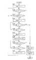
次に、上記の画像形成装置10の設置時における設定動作、と、運用時における消費電力の管理及び制御動作について説明する。図8は、画像形成装置10の設置時における設定動作を示したフローチャートであり、図9、図10は、画像形成装置10の運用時における消費電力の管理及び制御動作を示したフローチャートである。 Next, the setting operation when the
まず、画像形成装置10の設置時における設定動作について説明する。画像形成装置10では、上述したように、装置最大消費電力PE、装置待機消費電力PS、及び、加熱ヒータ負荷値ZCの設定は、通常、画像形成装置10の生産工場で行われており、消費電力管理制御演算部17に記憶されているものとする。そして、画像形成装置10の設定動作を開始するのに際して、最初に、電力源3からブレーカ5を介して接続されている全てのコンセント(上記のコンセント6を含む)に、負荷が全く接続されていないことを確認する。又、画像形成装置10の制御部33の第1スイッチ(SW)21、第2スイッチ(SW)22、及び、第2スイッチ(SW)22が、全てOFFになっていることを確認する。First, a setting operation when the
次に、図8において、第1スイッチ(SW)21をON、OFFするが、まず、ONすると(S1)、画像形成装置10の制御部33の電圧測定記憶部16により、無負荷電圧VOが測定されて記憶される(S2)。第1スイッチ(SW)21がOFFした後(S3)、第2スイッチ(SW)22をON、OFFするが、まず、ONすると(S4)、画像形成装置10の制御部33の電圧測定記憶部16により、基準負荷電圧VCが測定されて記憶される(S5)。Next, in FIG. 8, the first switch (SW) 21 is turned ON / OFF. When the first switch (SW) 21 is turned ON (S 1), the no-load voltage VO is detected by the voltage
次に、第2スイッチ(SW)22がOFFした後(S6)、第3スイッチ(SW)23をONする(S7)。すると、装置電源部11に電源が供給されて装置電源部11が立ち上がり、電源ライン25を介して画像形成装置10の各部に必要な電源が供給される(S8)。そこで、電圧測定記憶部16は、この電圧測定記憶部16に記憶されている無負荷電圧VO及び基準負荷電圧VCを、消費電力管理制御演算部17に提供し、消費電力管理制御演算部17がデータテーブルへ記憶する(S8)。Next, after the second switch (SW) 22 is turned off (S6), the third switch (SW) 23 is turned on (S7). Then, power is supplied to the apparatus
又、第3スイッチ(SW)23がONされた後、画像形成装置10の設置者等により、画像形成装置10の制御部33の表示部14及びキーボード15を用いて、ブレーカ最大許容電流IMの設定が行われるが、この設定が終了すると(S9)、消費電力管理制御演算部17により、最大許容消費電力PMが演算されてデータテーブルへ記憶される(S10)。又、この消費電力管理制御演算部17により、増加見込消費電力PDが演算されてデータテーブルへ記憶され(S10)、画像形成装置10の設定動作が終了する。In addition, after the third switch (SW) 23 is turned on, the installer of the
次に、画像形成装置10の運用時における消費電力の管理及び制御動作について、図9、図10を参照しながら説明する。ここでは、画像形成装置10の本来の目的であるモノクロ複写の一連の動作を、運転と称する。又、図9は、主として画像形成装置10の運転に関する動作を示したフローチャートであり、CPU12が主体となって行われる処理である。又、図10は、主として画像形成装置10の消費電力の管理及び制御に関する動作を示したフローチャートであり、消費電力管理制御演算部17が主体となって行われる処理である。この図9及び図10のフローチャートの各動作は、同時に並行して処理される。 Next, power management and control operations during operation of the
又、動作表示用のフラグとして、運転指令フラグF1、運転許可フラグF2、及び、停止指令フラグF3が用いられる。運転指令フラグF1は、CPU12から、消費電力管理制御演算部17に対して、画像形成装置10の運転の開始を指令するとセットされる。又、運転許可フラグF2は、消費電力管理制御演算部17が消費電力の観点から画像形成装置10の運転を許容できると判断すると、セットされる。又、停止指令フラグF3は、消費電力管理制御演算部17が、ブレーカ5の電力遮断を予想すると、セットされる。 Further, an operation command flag F1, an operation permission flag F2, and a stop command flag F3 are used as operation display flags. The operation command flag F <b> 1 is set when the
まず、図9に基づいて、画像形成装置10の運転に関する動作について説明する。画像形成装置10の最初の状態は、画像形成装置10の電源ケーブルの電源プラグ7が、電力源3からブレーカ5を介して電力が供給される電源コンセント6に挿入され、第3スイッチ(SW)23のみがONされている状態である。この状態は、画像形成装置10の待機状態である。 First, operations related to the operation of the
この待機状態で、図9において、まず、運転指令フラグF1をリセットする(S21)。そして、停止指令フラグF3をチェックし、停止指令フラグF3がセットされていないと(S22)、次に、画像形成装置10の操作者等により原稿搬送部に原稿が提供される等の複写開始操作が行われることにより、画像形成装置10の運転要求がなされていないかチェックする(S23)。運転要求がなされていないと、S22へ戻って、上記の処理を繰返し、運転要求がなされるまで待つ。 In this standby state, in FIG. 9, first, the operation command flag F1 is reset (S21). Then, the stop command flag F3 is checked, and if the stop command flag F3 is not set (S22), then a copy start operation such as an original being provided to the original transport unit by an operator of the
S23で画像形成装置10の運転要求がなされていると、運転指令フラグF1をセットした後(S24)、停止指令フラグF3をチェックし、停止指令フラグF3がセットされていないと(S25)、次に、運転許可フラグF2をチェックする(S26)。運転許可フラグF2がセットされていないと、S25へ戻って、上記の処理を繰返し、運転許可フラグF2がセットされるまで待つ。 If the operation request of the
S26で運転許可フラグF2がセットされていると、運転指令フラグF1をリセットした後(S27)、画像形成装置10の運転を開始する(S28)。そして、停止指令フラグF3をチェックし、停止指令フラグF3がセットされていないと(S29)、画像形成装置10の運転が終了しているか否かをチェックし(S30)、画像形成装置10の運転が終了していると(S30)、運転許可フラグF2をリセットして(S31)、S22へ戻り、上記の処理を繰返す。 If the operation permission flag F2 is set in S26, the operation command flag F1 is reset (S27), and then the operation of the
尚、上記の、S22、S25、或いは、S29において、停止指令フラグF3がセットされていると、画像形成装置10の制御部33の表示部14に、警告として、消費電力オーバによる運転停止を表示すると共に(S32)、画像形成装置10の運転を停止して(S33)、画像形成装置10の運転に関する動作を終了する。 If the stop command flag F3 is set in S22, S25, or S29 described above, the
次に、図10に基づいて、画像形成装置10の消費電力の管理及び制御に関する動作について、説明する。まず、運転許可フラグF2、及び、停止指令フラグF3をリセットする(S41)。そして、電圧測定記憶部16が、出力電圧VUを測定して記憶すると共に、消費電力管理制御演算部17に提供する(S42)。すると、消費電力管理制御演算部17は、この出力電圧VUをデータテーブルへ記憶すると共に、総使用消費電力PU及び増加可能消費電力PRを演算する(S43)。そして、この増加可能消費電力PRが、マイナスか否かをチェックし(S44)、増加可能消費電力PRがマイナスでないと(S44)、運転許可フラグF2をチェックする(S46)。Next, operations related to management and control of power consumption of the
運転許可フラグF2がセットされていると(S46)、S42へ戻り、上記の処理を繰返す。運転許可フラグF2がセットされていないと(S46)、運転指令フラグF1をチェックし(S47)、運転指令フラグF1がセットされていないと(S47)、S42へ戻り、上記の処理を繰返す。 If the operation permission flag F2 is set (S46), the process returns to S42 and the above process is repeated. If the operation permission flag F2 is not set (S46), the operation command flag F1 is checked (S47). If the operation command flag F1 is not set (S47), the process returns to S42 and the above processing is repeated.
S47で、運転指令フラグF1がセットされていると、画像形成装置10の運転が許容できるか否かを判断するために、上記の増加可能消費電力PRを、データテーブルに記憶されている画像形成装置10の増加見込消費電力PDと比較する(S48)。その結果、増加見込消費電力PDが、増加可能消費電力PRを超えると、即ち、増加見込消費電力PDが、増加可能消費電力PR以下でないと(S49)、増加見込消費電力PDを現時点で新たに増加させると、電力源3から供給されて消費されている消費電力が、電力源3のブレーカ5の最大許容消費電力PMを超えるので、ブレーカ5の電力遮断が予想される。そこで、画像形成装置10の制御部33の表示部14に、警告として、運転開始遅延表示をして(S50)、S42へ戻り、上記の処理を繰返して、増加見込消費電力PDが、増加可能消費電力PRを超えない状態になるまで待つ。In S47, the operation command flag F1 is set, in order to determine whether the operation of the
S49で、増加見込消費電力PDが、増加可能消費電力PRを超えないと、即ち、増加見込消費電力PDが、増加可能消費電力PR以下であると、増加見込消費電力PDを現時点で新たに増加させても、電力源3から供給されて消費されている消費電力が、電力源3のブレーカ5の最大許容消費電力PMを超えないので、ブレーカ5の電力遮断は生じえない。そこで、運転許可フラグF2をセットすると共に(S51)、運転開始遅延が表示されていると(S52)、運転開始遅延表示を消灯して(S53)、S42へ戻り、上記の処理を繰返す。In S49, when the increase expected power consumption PD does not exceed possible increase power consumption PR, i.e., increase expected power consumption PD is, is not more than possible increase power PR, the increase expected power consumption PD even newly increased at this time, the power consumption that is consumed is supplied from the
尚、上記のS44で、増加可能消費電力PRが、マイナスであれば、電力源3から供給されて消費されている消費電力が、電力源3のブレーカ5の最大許容消費電力PMを超えており、ブレーカ5の電力遮断が予想されるので、停止指令フラグF3をセットして(S45)、画像形成装置10の消費電力の管理及び制御に関する動作を終了する。Incidentally, in S44 described above, an increase can be consumed power PR is, if the negative power consumption that is consumed is supplied from the
上記の画像形成装置10によれば、この画像形成装置10を使用するために起電力及び内部抵抗を有する電力源3から電力が供給されるコンセント6に、この画像形成装置10を接続した際における総使用消費電力PUを、演算することができる。この総使用消費電力PUは、この画像形成装置10単独で、この画像形成装置10に対する消費電力の管理及び制御に、役立てることができる。According to the
又、起電力及び内部抵抗を有する電力源3から、値の既知である最大許容電流IMのブレーカ5を介して、電力が供給されるコンセント6に、この画像形成装置10を接続した場合に、この画像形成装置10に最大許容電流IMを記憶させることによって、上記の電力源3に対するブレーカ5による電力遮断を伴わずに使用可能な最大許容消費電力PMを、演算することができる。この最大許容消費電力PMは、この画像形成装置10単独で、この画像形成装置10に対する消費電力の管理及び制御に、役立てることができる。When the
この場合に、最大許容消費電力PMから総使用消費電力PUを減算して、増加可能消費電力PRを求めることができる。又、増加可能消費電力PRが、マイナスとなると、消費電力オーバの警告を発生することができる。更に、増加可能消費電力PRが、マイナスとなると、画像形成装置10の動作を停止するようにすることができる。従って、上記の画像形成装置10単独で、この画像形成装置10に対する消費電力の的確な管理及び制御を行うことができる。In this case, by subtracting the total used power PU from the maximum allowable power dissipation PM, it is possible to determine the possible increase power consumption PR. Further, possible increase power consumption PR is, becomes negative, it is possible to generate a warning power consumption over. Further, possible increase power consumption PR is, becomes negative, can be made to stop the operation of the
又、上記の画像形成装置10に、予め、画像形成装置10の装置最大消費電力PEと装置待機消費電力PSとを記憶させておくことによって、増加見込消費電力PDを演算することにより、この増加見込消費電力PDと増加可能消費電力PRとを比較して、増加見込消費電力PDが増加可能消費電力PRを超えなければ、待機状態から運転状態へ許容するようにすることができる。又、増加見込消費電力PDが増加可能消費電力PRを超えと、警告を発生するようにすることができる。従って、画像形成装置10単独で、この画像形成装置10に対する消費電力の的確な管理及び制御を行うことができる。Further, the
上記の本実施の形態では、消費電力管理制御演算部17のメモリに設けられたデータテーブルの設定値エリアに、画像形成装置10の装置最大消費電力PEと、装置待機消費電力PSとが記憶される。そして、前述の内部負荷を1つとした場合における、前述の内部負荷最大消費電力PCnに相当する増加見込消費電力PDが、消費電力管理制御演算部17により、装置最大消費電力PEと、装置待機消費電力PSから演算される。即ち、上記の画像形成装置10では、画像形成装置10における消費電力の管理及び制御としては、装置最大消費電力PEと、装置待機消費電力PSとの差である増加見込消費電力PDを、画像形成装置10における消費電力の管理及び制御の対象としている。In the present embodiment described above, the setting value area of data table provided in the memory power management
しかし、画像形成装置10における消費電力の管理及び制御の対象としては、上記の場合に限られない。例えば、上記の本実施の形態において、画像形成装置10を構成するさまざまな構成要素を、前述の複数の内部負荷と捉えて、これらの最大消費電力を消費電力管理制御演算部17のメモリに設けられたデータテーブルの設定値エリアに記憶する。そして、画像形成装置10の動作の各工程を細分化して、この工程における増加見込消費電力を演算してデータテーブルの演算値エリアに記憶することにより、画像形成装置10における消費電力の更にきめ細かい管理及び制御を行うことができる。この場合に、例えば、オプション等を使用している場合に、消費電力の状態によっては、このオプション等の電源をOFFして切離す等の制御をすることもできる。 However, the object of power consumption management and control in the
或いは、データテーブルの設定値エリアに、消費電力の管理及び制御の対象とするデータを記憶し、このデータを用いて消費電力の管理及び制御を行うようにしてもよい。この場合に、データテーブルの設定値エリアには、消費電力の管理及び制御の対象とするデータとして、画像形成装置を構成するさまざまな構成要素を、前述の複数の内部負荷と捉えて、画像形成装置における複数の構成要素の最大消費電力を記憶するようにしてもよい。 Alternatively, data to be managed and controlled for power consumption may be stored in the set value area of the data table, and the power consumption may be managed and controlled using this data. In this case, in the set value area of the data table, various data constituting the image forming apparatus as data to be managed and controlled for power consumption are regarded as the plurality of internal loads described above, and image formation is performed. You may make it memorize | store the maximum power consumption of the some component in an apparatus.
又、上記の本実施の形態では、基準負荷として、モノクロ画像記録制御部19における定着ローラ74の内部に備えられた加熱ヒータ76を用いている。しかし、これには限られず、例えば、画像形成装置のオプション装置を用いるようにしてもよい。上記のオプション装置としては、例えば、後処理装置や、大容量給紙カセット、複数ビン排紙トレイ等である。これらのオプション装置は、上記のモノクロ画像記録制御部19における定着ローラ74の内部に備えられた加熱ヒータ76と同様、比較的、消費電力が大きく、上記の基準負荷としてふさわしいと考えられる。 In the present embodiment, the
上述した本実施の形態における説明では、電子装置として画像形成装置を用いて説明しているが、本発明の電子装置はこれには限られず、電力源からブレーカを介して配線されているコンセント等に接続して使用される電子装置であれば、どのようなものでも、本発明の対象とすることができる。 In the above description of the present embodiment, an image forming apparatus is used as the electronic apparatus. However, the electronic apparatus of the present invention is not limited to this, and an outlet wired from a power source through a breaker or the like. Any electronic device that is connected to and used in the present invention can be the subject of the present invention.
1 起電力
2 内部抵抗
3 電力源
4 電力源出力端子
5 ブレーカ
6 電源コンセント
7 電源プラグ
10 画像形成装置
11 装置電源部
12 CPU
13 メモリ
14 表示部
15 キーボード
16 電圧測定記憶部
17 消費電力管理制御演算部
18 モノクロスキャナ制御部
19 モノクロ画像記録制御部
21 第1スイッチ(SW)
22 第2スイッチ(SW)
23 第3スイッチ(SW)
24 制御ライン
25 電源ライン
31 モノクロスキャナ部
32 モノクロ画像記録部
33 制御部
41 第1記録用紙収納トレイ
42 第2記録用紙収納トレイ
43 第3記録用紙収納トレイ
44 第4記録用紙収納トレイ
51 水平供給搬送路
52 水平排出搬送路
53 第1垂直搬送路
54 第2垂直搬送路
55 第3垂直搬送路
56 水平帰還搬送路
57 排出収容トレイ
70 モノクロ画像形成ユニット
71 感光体ドラム
72 加圧ローラ
73 定着ユニット
74 定着ローラ
75 加圧ローラ
76 加熱ヒータDESCRIPTION OF
DESCRIPTION OF
22 Second switch (SW)
23 Third switch (SW)
24
Claims (10)
Translated fromJapanese前記電力源に対して無負荷状態となるようにして、前記電子装置が前記電力源出力端子に接続された際に、前記電力源出力端子の電圧である無負荷電圧VOを予め測定して記憶し、
前記電力源に対する負荷が前記基準負荷のみとなるようにして、前記電子装置が前記電力源出力端子に接続された際に、前記電力源出力端子の電圧である基準負荷電圧VCを予め測定して記憶し、
他の電力負荷が接続されている前記電力源出力端子に前記電子装置が並列接続された際に、該電力源出力端子における出力電圧VUを測定して記憶する電圧測定記憶手段と、
前記基準負荷の値ZCを予め記憶していると共に、該基準負荷の値ZC、前記無負荷電圧VO、前記基準負荷電圧VC、及び、前記出力電圧VUを基にして、前記並列接続時における前記電力源に対する総使用消費電力PUを演算し、
前記最大許容電流IMを予め記憶していると共に、該最大許容電流IM、前記基準負荷の値ZC、前記無負荷電圧VO、及び、前記基準負荷電圧VCを基にして、前記ブレーカによる電力遮断を伴わずに使用可能な最大許容消費電力PMを演算する消費電力演算手段と、
前記最大許容消費電力PMから前記総使用消費電力PUを減算して、増加可能消費電力PRを求める消費電力管理制御手段と、
を備えることを特徴とする電子装置。A reference load that is used in connection with a power source output terminal towhich power is suppliedvia a breaker witha maximum allowable current IMwhosevalue is known from a power source having an electromotive force and an internal resistance, and whose value is known An electronic device comprising at least
As a no-load state with respect to the power source, the when the electronic device is connected to the power source output terminal,advance measurement saysthe no-load voltage VO which is the voltage of the power source output terminal Remember,
As load on the power source is only the reference load, when the electronic device is connected to the power source output terminal,advance measurement the reference load voltage VC is the voltage of the power source output terminaland and stored,
When the electronic device isparallel connected to the power source outputterminal other power load is connected, a voltage measuring storage means formeasurement and storesthe output voltage VU at said power source output terminal ,
Withpreviously stores the value ZCbefore Symbol reference load, the value of the reference load ZC, the no-load voltage VO, the reference load voltage VC, and, based on the output voltage VU, Calculate the total power consumption PU for the power source at the time of theparallel connection,
With previously storesthemaximum permissible current IM, said maximum permissible current IM, the value ZCof the referenceload,the load voltage VO, and,based onthe reference load voltage VC, the a power calculating means forcalculating amaximum power dissipation PMusable without power interruption by the breaker,
Whereinby subtracting themaximum allowable power PMfrom the total consumption power PU,the power management control means for determining apossible increase power consumption PR,
An electronic device comprising:
前記消費電力管理制御手段は、全ての前記内部負荷の内部負荷最大消費電力PCnを予め記憶すると共に、前記内部負荷最大消費電力PCnと前記増加可能消費電力PRとを比較して、前記内部負荷最大消費電力PCnが前記増加可能消費電力PRを超えなければ、前記内部負荷への電力供給を許容する請求項1〜3のいずれか1項に記載の電子装置。The electronic device is provided with a single or a plurality of internal loads,
It said power management control unitis configured topreviously store the internal load maximum power consumption PCn of the internal loads ofall hand, by comparing the internal load maximum power consumption PCn and the possible increase power PR, if the internal load maximum power consumption PCn does not exceed the possible increase power PR, the electronic device according to any one of claims1 to3, allowing the power supply to the internal load.
Priority Applications (1)
| Application Number | Priority Date | Filing Date | Title |
|---|---|---|---|
| JP2006015511AJP4818740B2 (en) | 2006-01-24 | 2006-01-24 | Electronic equipment |
Applications Claiming Priority (1)
| Application Number | Priority Date | Filing Date | Title |
|---|---|---|---|
| JP2006015511AJP4818740B2 (en) | 2006-01-24 | 2006-01-24 | Electronic equipment |
Publications (2)
| Publication Number | Publication Date |
|---|---|
| JP2007199204A JP2007199204A (en) | 2007-08-09 |
| JP4818740B2true JP4818740B2 (en) | 2011-11-16 |
Family
ID=38453899
Family Applications (1)
| Application Number | Title | Priority Date | Filing Date |
|---|---|---|---|
| JP2006015511AActiveJP4818740B2 (en) | 2006-01-24 | 2006-01-24 | Electronic equipment |
Country Status (1)
| Country | Link |
|---|---|
| JP (1) | JP4818740B2 (en) |
Families Citing this family (3)
| Publication number | Priority date | Publication date | Assignee | Title |
|---|---|---|---|---|
| JP4922362B2 (en)* | 2009-07-27 | 2012-04-25 | 株式会社沖データ | Printing apparatus, printing control apparatus, and printing system |
| JP5515798B2 (en)* | 2010-01-29 | 2014-06-11 | 富士通株式会社 | Power control apparatus, power system, and power control program |
| JP5501796B2 (en) | 2010-02-24 | 2014-05-28 | 富士通株式会社 | Distribution network estimation apparatus and distribution network estimation method |
Family Cites Families (6)
| Publication number | Priority date | Publication date | Assignee | Title |
|---|---|---|---|---|
| JPH02123925A (en)* | 1988-10-31 | 1990-05-11 | Mita Ind Co Ltd | Electric equipment controlling system and adapter |
| JPH04184457A (en)* | 1990-11-20 | 1992-07-01 | Fujitsu Ltd | An image forming device and a system including a plurality of such devices |
| JPH0538050A (en)* | 1991-07-24 | 1993-02-12 | Ricoh Co Ltd | Image forming apparatus control device |
| JPH0916032A (en)* | 1995-06-29 | 1997-01-17 | Ricoh Co Ltd | Drive controller |
| JP3402953B2 (en)* | 1996-09-13 | 2003-05-06 | 株式会社東芝 | Communication method, communication system and communication device |
| JP2003255777A (en)* | 2002-02-28 | 2003-09-10 | Konica Corp | Method for managing power source for image forming apparatus, and image forming apparatus |
- 2006
- 2006-01-24JPJP2006015511Apatent/JP4818740B2/enactiveActive
Also Published As
| Publication number | Publication date |
|---|---|
| JP2007199204A (en) | 2007-08-09 |
Similar Documents
| Publication | Publication Date | Title |
|---|---|---|
| JP5838586B2 (en) | Image forming apparatus | |
| JP2010066824A (en) | Power supply system and power supply method | |
| JP4818740B2 (en) | Electronic equipment | |
| US20140281632A1 (en) | Electronic apparatus that measures power during power saving state, method of controlling the same, and storage medium | |
| JP2017044699A (en) | Deterioration detection apparatus, induction heating apparatus, image forming apparatus, and deterioration detection method | |
| KR101499304B1 (en) | Information processing apparatus and control method of information processing apparatus | |
| JP2011237611A (en) | Device and program for calculating power consumption | |
| JP2016102912A (en) | Power supply device and image forming device | |
| JP2006101592A (en) | Control device and power supply control method | |
| JP4323272B2 (en) | Image forming apparatus | |
| JP2011010022A (en) | Control apparatus and image forming apparatus | |
| JP5458712B2 (en) | Power supply device, power supply control system, and power supply control program | |
| JP6874434B2 (en) | Electrical equipment and power management method | |
| JP2004341755A (en) | Information processing device | |
| JP5817216B2 (en) | Image forming apparatus | |
| JP6175884B2 (en) | Power supply monitoring device, image processing device | |
| JP6687257B2 (en) | Power supply device, power supply system, power supply device control method, and power supply device control program | |
| JP2014176153A (en) | Electric equipment, and control method and program of electric equipment | |
| JP6483648B2 (en) | Factor determination device, factor determination method, factor determination program, and communication device | |
| JP2021196839A (en) | Power consumption management system | |
| JPH06253454A (en) | Electric equipment and image forming equipment having power operation control means | |
| JP2008021243A (en) | Data backup system and power drop-in detecting device | |
| JP5893698B2 (en) | Information processing apparatus, charging method, and program | |
| JP2017126015A (en) | Life prediction method for electronic equipment, image forming apparatus, and energy conversion apparatus | |
| JP5970418B2 (en) | Electronics |
Legal Events
| Date | Code | Title | Description |
|---|---|---|---|
| A621 | Written request for application examination | Free format text:JAPANESE INTERMEDIATE CODE: A621 Effective date:20080220 | |
| A131 | Notification of reasons for refusal | Free format text:JAPANESE INTERMEDIATE CODE: A131 Effective date:20110222 | |
| A521 | Written amendment | Free format text:JAPANESE INTERMEDIATE CODE: A523 Effective date:20110307 | |
| RD02 | Notification of acceptance of power of attorney | Free format text:JAPANESE INTERMEDIATE CODE: A7422 Effective date:20110307 | |
| TRDD | Decision of grant or rejection written | ||
| A01 | Written decision to grant a patent or to grant a registration (utility model) | Free format text:JAPANESE INTERMEDIATE CODE: A01 Effective date:20110830 | |
| A01 | Written decision to grant a patent or to grant a registration (utility model) | Free format text:JAPANESE INTERMEDIATE CODE: A01 | |
| A61 | First payment of annual fees (during grant procedure) | Free format text:JAPANESE INTERMEDIATE CODE: A61 Effective date:20110831 | |
| FPAY | Renewal fee payment (event date is renewal date of database) | Free format text:PAYMENT UNTIL: 20140909 Year of fee payment:3 | |
| R150 | Certificate of patent or registration of utility model | Ref document number:4818740 Country of ref document:JP Free format text:JAPANESE INTERMEDIATE CODE: R150 Free format text:JAPANESE INTERMEDIATE CODE: R150 |