JP4817715B2 - Magnetic resonance imaging system - Google Patents
Magnetic resonance imaging systemDownload PDFInfo
- Publication number
- JP4817715B2 JP4817715B2JP2005151097AJP2005151097AJP4817715B2JP 4817715 B2JP4817715 B2JP 4817715B2JP 2005151097 AJP2005151097 AJP 2005151097AJP 2005151097 AJP2005151097 AJP 2005151097AJP 4817715 B2JP4817715 B2JP 4817715B2
- Authority
- JP
- Japan
- Prior art keywords
- receiving
- sensitivity
- coils
- phase
- encoding direction
- Prior art date
- Legal status (The legal status is an assumption and is not a legal conclusion. Google has not performed a legal analysis and makes no representation as to the accuracy of the status listed.)
- Expired - Lifetime
Links
Images


Landscapes
- Magnetic Resonance Imaging Apparatus (AREA)
Description
Translated fromJapanese本発明は、磁気共鳴イメージング(以下、MRIと称す)装置に関し、特にパラレルMRIに適したMRI装置に関する。 The present invention relates to a magnetic resonance imaging (hereinafter referred to as MRI) apparatus, and more particularly to an MRI apparatus suitable for parallel MRI.
MRI装置においては、高速撮像方法として、複数の高周波(RF)受信コイルを用いたパラレルMRIが用いられる。この方法は、複数のRF受信コイルを用いて被検体の核磁気共鳴信号を同時に受信した後、得られた受信信号を、各RF受信コイルの感度分布を表す行列式の逆行列を用いてパラレル展開する演算を行うことにより、被検体の磁化分布を求める。得られた磁化分布を用いて画像再構成を行う。パラレル展開の演算方法は、非特許文献1に記載されている。このように、受信信号を行列演算することにより、通常位相エンコードを間引いた場合に画像に生じる折り返しアーチファクトを除去することができるため、位相エンコードを間引いた高速撮像を行うことが可能である。 In the MRI apparatus, parallel MRI using a plurality of radio frequency (RF) receiving coils is used as a high-speed imaging method. In this method, a plurality of RF receiving coils are used to simultaneously receive a subject's nuclear magnetic resonance signals, and the obtained received signals are parallelized using a determinant inverse matrix representing the sensitivity distribution of each RF receiving coil. The magnetization distribution of the subject is obtained by performing an unfolding operation. Image reconstruction is performed using the obtained magnetization distribution. The parallel expansion calculation method is described in Non-Patent Document 1. In this way, by performing matrix operation on the received signal, aliasing artifacts generated in the image when the normal phase encoding is thinned out can be removed, so that high-speed imaging with thinned phase encoding can be performed.
パラレルMRI用のRF受信コイルとしては、本来は視野拡大し、高感度化を図る目的のマルチプルアレイコイルが用いられていた。マルチプルアレイコイルは、相対的に高感度な小型受信コイルを複数個並べて配置したものであり、パラレルMRIに用いた場合には、位相エンコード方向をマルチプルアレイコイルの並びの向きに応じて設定する必要があり、位相エンコード方向の設定の自由度が制限される。また、小型受信コイルを複数並べる構造であるため、表面感度は高くなるが、中心感度を高めることが難しい。 As an RF receiving coil for parallel MRI, a multiple array coil was originally used for the purpose of enlarging the field of view and increasing the sensitivity. The multiple array coil is a plurality of relatively sensitive small receiving coils arranged side by side, and when used for parallel MRI, it is necessary to set the phase encoding direction according to the direction of the array of multiple array coils. The degree of freedom in setting the phase encoding direction is limited. In addition, since a plurality of small receiving coils are arranged, the surface sensitivity is increased, but it is difficult to increase the center sensitivity.
そこで、パラレルMRIに適したRF受信コイルとして、特許文献1には、感度分布が互いに大きく異なるような複数のコイルを組み合わせて配置した受信コイルが提案されている。例えば、比較的大視野のRF受信コイルと、互いに直交する3方向に配置された少なくとも3組の比較的小視野のRF受信コイルとを組み合わせたものが開示されている。特許文献1に記載のRF受信コイルを用いることにより、マルチプルアレイコイルと比較して中心感度を高め、かつ、位相エンコード方向の自由度を高めることができる。
上記特許文献1に記載のRF受信コイルは、大視野用コイルと小視野用コイルとを複数組み合わせて配置するため、受信コイル間に磁気的結合が生じやすく、これを避けるために各コイルの形状および配置を設計する必要がある。例えば、大視野用コイルと同じ方向に感度を持つ小視野用コイルを配置することができない等の制限があるため、位相エンコード方向が制限される。 Since the RF receiving coil described in Patent Document 1 is arranged by combining a plurality of large-field coils and small-field coils, magnetic coupling is likely to occur between the receiving coils, and the shape of each coil is avoided to avoid this. And you need to design the arrangement. For example, the phase encoding direction is limited because there is a limitation that a small-field coil having sensitivity in the same direction as the large-field coil cannot be arranged.
本発明の目的は、中心感度が高く、かつ、位相エンコード方向の自由度の高いパラレルMRI用受信コイルを備えたMRI装置を提供することにある。 An object of the present invention is to provide an MRI apparatus including a parallel MRI receiving coil having high center sensitivity and high degree of freedom in a phase encoding direction.
上記目的を達成するために、本発明では以下のようなMRI装置を提供する。すなわち、被検体が配置される空間に静磁場を発生する静磁場発生部と、前記空間に所定の方向の傾斜磁場を印加する傾斜磁場発生部と、被検体に高周波磁場パルスを印加する高周波磁場照射部と、被検体からの核磁気共鳴信号を受信する複数の受信コイルと、該複数の受信コイルの受信した信号を該受信コイルの感度分布を用いて演算処理して画像再構成を行う信号処理部とを有するMRI装置において、複数の受信コイルは、撮像空間に同時に配置され、核磁気共鳴信号を同時に受信し、複数の受信コイルのうち少なくとも一つは、受信感度の位相成分が、所定の方向について、分布を有することを特徴とするものである。これにより、磁気的結合の小さい受信コイルを組み合わせることができるため、受信コイルの組み合わせの自由度が高まる。よって、中心感度が高く、かつ、位相エンコード方向の自由度の高い受信コイルを提供できる。 In order to achieve the above object, the present invention provides the following MRI apparatus. That is, a static magnetic field generator that generates a static magnetic field in a space in which the subject is arranged, a gradient magnetic field generator that applies a gradient magnetic field in a predetermined direction to the space, and a high-frequency magnetic field that applies a high-frequency magnetic field pulse to the subject An irradiation unit, a plurality of receiving coils that receive nuclear magnetic resonance signals from the subject, and a signal that performs image processing by performing arithmetic processing on the signals received by the plurality of receiving coils using the sensitivity distribution of the receiving coils In an MRI apparatus having a processing unit, a plurality of receiving coils are simultaneously arranged in an imaging space and receive nuclear magnetic resonance signals at the same time, and at least one of the plurality of receiving coils has a phase component of reception sensitivity of a predetermined value. It has a distribution in the direction of. Thereby, since a receiving coil with small magnetic coupling can be combined, the freedom degree of the combination of a receiving coil increases. Therefore, it is possible to provide a receiving coil having a high center sensitivity and a high degree of freedom in the phase encoding direction.
上記複数の受信コイルのうち、受信感度の位相成分の分布のない受信コイルのうちの少なくも1つは、撮像野の中心領域の感度が端部領域の感度よりも大きいものを用いることができる。これにより、後述する式[3]の逆行列が必ず存在するため、パラレル展開を行うことが可能になり、かつ、中心感度を高めることができる。 Among the plurality of receiving coils, at least one of the receiving coils having no distribution of the phase component of the receiving sensitivity can be used in which the sensitivity of the central region of the imaging field is larger than the sensitivity of the end region. . Thereby, since an inverse matrix of equation [3] to be described later always exists, parallel expansion can be performed and the center sensitivity can be increased.
受信感度の位相成分に分布を有する前記受信コイルは、位相差が180°であるものを用いることができる。これにより、受信感度の位相差を、受信感度の実数部の符号として表すことができるため、受信信号の絶対値成分は低下せず、画像劣化の少ないパラレルMRIを行うことができる。 A receiving coil having a phase difference of 180 ° can be used as the receiving coil having a distribution of phase components of receiving sensitivity. Thereby, the phase difference of the reception sensitivity can be expressed as the sign of the real part of the reception sensitivity, so that the absolute value component of the reception signal does not decrease and parallel MRI with little image degradation can be performed.
受信コイルを構成する複数の受信コイルのうちの2以上を、受信感度の位相成分に分布を有する受信コイルとすることが可能であり、これらを位相成分に分布を有する方向が、互いに直交するように配置することができる。これにより、位相エンコード方向を直交するいずれの方向に設定することも可能である。 Two or more of the plurality of receiving coils constituting the receiving coil can be a receiving coil having a distribution in the phase component of the receiving sensitivity, and the directions having the distribution in the phase component are orthogonal to each other. Can be arranged. Thereby, the phase encoding direction can be set to any direction orthogonal to each other.
受信感度の位相成分に分布を有する受信コイルの1つは、所定の方向に位相分布が複数回変化しているものを用いることができる。また、受信感度の位相成分に分布を有する受信コイルの1つとして、8の字型の受信コイルを用いることができる。この8の字型コイルを連結して用いることにより、連結する方向によって受信感度の位相分布を生じさせる方向を任意に設定することができるため、位相エンコード方向を設定の自由度を高めることが可能である。 As one of the receiving coils having a distribution in the phase component of the receiving sensitivity, a receiving coil whose phase distribution changes a plurality of times in a predetermined direction can be used. Further, as one of the receiving coils having a distribution in the phase component of the receiving sensitivity, an 8-shaped receiving coil can be used. By connecting and using these 8-shaped coils, the direction in which the phase distribution of the reception sensitivity is generated can be arbitrarily set according to the connecting direction, so that the degree of freedom in setting the phase encoding direction can be increased. It is.
本発明では、受信感度が位相成分の分布を有する受信コイルを用いることにより、中心感度が高く、かつ、位相エンコード方向の自由度の高いパラレルMRI用受信コイルが容易に構成でき、高感度で撮像の自由度の高いMRI装置を提供することができる。 In the present invention, by using a receiving coil whose receiving sensitivity has a phase component distribution, a parallel MRI receiving coil with high center sensitivity and high degree of freedom in the phase encoding direction can be easily configured, and imaging is performed with high sensitivity. An MRI apparatus with a high degree of freedom can be provided.
以下、本発明の実施形態について図面を用いて説明する。
まず、第1の実施の形態のMRI装置の構成を図1を用いて具体的に説明する。本MRI装置は、静磁場発生系22と、傾斜磁場発生系4と、送信系3と、受信系5と、信号処理系6と、シーケンサ2と、中央処理装置(CPU)1と、被検体11を搭載するベッド27とを備えている。Hereinafter, embodiments of the present invention will be described with reference to the drawings.
First, the configuration of the MRI apparatus according to the first embodiment will be specifically described with reference to FIG. This MRI apparatus includes a static magnetic field generation system 22, a gradient magnetic field generation system 4, a transmission system 3, a reception system 5, a signal processing system 6, a
シーケンサ2は、CPU1からの制御指令に基づいて動作し、被検体11のデータを収集する所定のパルスシーケンスの実行に必要な種々の命令を送信系3、傾斜磁場発生系4、受信系5に送信する。 The
静磁場発生系22は、静磁場発生源を有し、ベッド27に搭載された被検体11が配置される空間に、その体軸方向または体軸と直交する方向に均一な静磁場を発生させる。静磁場発生源としては、永久磁石、常電導磁石または超電導磁石を用いることができる。 The static magnetic field generation system 22 has a static magnetic field generation source, and generates a uniform static magnetic field in a body axis direction or a direction perpendicular to the body axis in a space in which the
傾斜磁場発生系4は、傾斜磁場コイル13a、13bと、傾斜磁場コイル13a、13bに電流を供給する傾斜磁場電源12とを有する。傾斜磁場コイル13a、13bは、被検体11に対して、互いに直交するデカルト座標軸方向(X,Y,Z軸方向)にそれぞれ独立に傾斜磁場Gs,Gp,Gfを印加する構成を備えている。シーケンサ2からの命令に従って傾斜磁場電源12が傾斜磁場コイル13a、13bに駆動電流を供給することにより、被検体11には、スライス面を設定するスライス方向傾斜磁場パルス(Gs)と、核磁気共鳴信号に対して位置情報をエンコードするための位相エンコード方向傾斜磁場パルス(Gp)および周波数エンコード方向傾斜磁場パルス(Gf)が所定のタイミングでそれぞれ印加される。 The gradient magnetic field generation system 4 includes gradient
送信系3は、高周波発振器7と変調器8と高周波増幅器9a〜9dと送信コイル10a、10bとを有する。高周波発振器7が発振した高周波信号は、シーケンサ2からの信号に応じて変調器8で変調され、高周波増幅器9a〜9dで増幅され、被検体11に近接して配置された送信コイル10a、10bに供給される。これにより、被検体11に核磁気共鳴を起こさせるパルス状の高周波電磁波が、送信コイル10a、10bから被検体11に所定のタイミングで照射される。 The transmission system 3 includes a high-frequency oscillator 7, a modulator 8, high-
受信系5は、被検体11から放出される核磁気共鳴信号(エコー信号)を受信し、検出するものであり、受信コイル14とプリアンプ15と直交位相検波器16とA/D変換器17とを備えている。エコー信号は、被検体11に近接して配置された受信コイル14によって受信され、プリアンプ15および直交位相検波器16によって所望の信号が検出され、A/D変換器17でディジタル量に変換され、CPU1(信号処理系6)に送られる。受信コイル14の詳細については後述する。 The receiving system 5 receives and detects a nuclear magnetic resonance signal (echo signal) emitted from the
信号処理系6は、CPU1と磁気ディスク18や光ディスク19等の外部記憶装置と、再構成した画像等を表示するCRT20と、操作者からの指示の入力を受け付けるためのキーボード21等の入力装置とを有している。CPU1は、受信系5からのデータを受け取ると、信号処理、画像再構成処理等を実行し、被検体11の所望の断層像等をCRTに表示するとともに外部記憶装置(例えば磁気ディスク18)にデータを格納する。また、CPU1は、キーボード21等の入力装置が操作者から撮像方法、撮像条件等を指示する入力を受け付けた場合には、CPU1に内蔵するメモリに格納されたプログラムを実行することにより、指示された撮像方法を実現するパルスシーケンスを作成し、シーケンサ2に受け渡し、撮像を実行させる。 The signal processing system 6 includes an external storage device such as the CPU 1 and the
つぎに、本実施の形態のMRI装置における撮像方法および信号処理方法について説明する。 Next, an imaging method and a signal processing method in the MRI apparatus of the present embodiment will be described.
CPU1は、操作者から入力装置(キーボード21等)を介して、パラレルMRIで撮像を実行する旨の指示および倍速数の指定を受けた場合には、位相エンコードのエンコードステップを指示された倍速数に対応する間引き率で間引いたパルスシーケンスを作成する。パラレルMRIで用いる撮像方法は、一般的なスピンエコーシーケンスやグラディエントエコーシーケンス等の操作の所望のシーケンスを用いる。例えば、グラディエントエコーシーケンスを採用する場合には、RFパルスおよびスライス選択傾斜磁場パルスを印加した後、位相エンコード傾斜磁場パルスおよび読み出し傾斜磁場パルスを印加し、RFパルスの印加から所定のエコータイム(TE)経過後にエコー信号を計測する。これを位相エンコード傾斜磁場パルスの強度を変えながら、所定の位相エンコード数繰り返す。この際、パラレルMRIでは、指示された倍速数に対応する間引き率で位相エンコード数を間引いて撮像を行うため、高速で撮像することができる。 When the CPU 1 receives an instruction to execute imaging by parallel MRI and designation of the double speed number from the operator via the input device (
ここで、本実施の形態でパラレルMRI用受信コイル14について説明する。
本実施の形態の受信コイル14は、複数の受信コイルを組み合わせて構成され、このうち少なくとも一つの受信コイルは、感度の位相成分が位相エンコード方向に分布を有する。具体的には、図2(a)のように受信コイル14として、サドル型の受信コイル40と、受信コイル41とを組み合わせて配置したものを用いることができる。Here, the parallel
The receiving
受信コイル41は、一対の小径ソレノイドコイルを位相エンコード方向(X方向)に対向配置し、両者を直列に接続した構造である。この受信コイル41の受信感度の絶対値成分411は、図2(b)に示したように撮像野(FOV)の位相エンコード方向(X方向)両端部に高感度領域を有する。また、受信感度の位相成分412は、図2(c)に示したように位相エンコード方向(X方向)の一方の側の感度が他方の側に感度に対し180°の位相差を有しており、受信感度の位相成分が位相エンコード方向に分布を持つ。 The receiving
一方、サドル型の受信コイル40は、図2(b)に示したように、受信感度の絶対値成分401がFOVの位相エンコード方向の中心部付近で高感度であり、受信コイル41とは異なる位置に高感度領域が存在する。また、受信コイル40は、コイルを流れる電流ループの向きの相違から受信コイル40に対して磁気的結合(干渉)を生じにくく、受信コイル41と組み合わせて用いることができる。また、受信コイル40は、図2(c)から明らかなように、受信感度の位相成分402が位相エンコード方向(X方向)について一様である。 On the other hand, as shown in FIG. 2B, the saddle-
本実施の形態では、このような受信コイル40,41を組み合わせた受信コイル14の受信信号を用いて、パラレルMRIにより位相エンコード数を間引いて撮像を行い、得られた受信信号について以下のように行列演算を行う。この演算により、位相エンコード数を間引いたことにより生じる折り返しアーチファクトを除去した画像データ(磁化分布)を得る。 In the present embodiment, imaging is performed by thinning out the number of phase encodes by parallel MRI using the reception signal of the
例えば、図2(a)の構成の受信コイル14を用いて2倍速のパラレルMRIを行った場合、図2(b)、(c)に示すA点とB点が重なりあった受信信号が得られる。ここで、A点での受信コイル40の感度をC40A、A点での受信コイル41の感度をC41A、B点での受信コイル40の感度をC40B、B点での受信コイル41の感度をC41B、A点の被検体11の磁化の大きさをPA、B点の被検体11の磁化の大きさをPBとすると、受信コイル40より得られる信号S40A+B、受信コイル41より得られる信号S41A+B、は、感度C40A、C40Bおよび感度C41A、C41Bを要素とする行列を用いて、式[1]のように表される。
よって、重なりあった信号S40A+B、S41A+Bより被検体11の磁化PA、PBを求めるには、上記行列式[1]を展開することにより、次式[2]により求められる。
よって、パラレル展開を行う為には、式[3]で表される逆行列を求める必要がある。
受信コイル40、41の感度分布は、絶対値成分を実部、位相成分を虚部とする複素数で表される。本実施の形態では、図2(b)、(c)より、受信コイル40及び受信コイル41の感度の絶対値成分は、A点、B点のいずれも1である。位相成分は、受信コイル41のB点の感度のみが180°であり、受信コイル40のA,B点の感度および受信コイル41のA点の感度は、いずれも0°である。よって、受信コイル40、41の感度C40A、C40B、C41A、C41Bを要素とする行列は、下式[4]のように表される。
式[4]は正則行列であるため、逆行列式[3]が必ず存在する。よって、上式[2]を解くことにより被検体11の磁化分布PA、PBを求めることができる。Since the equation [4] is a regular matrix, the inverse determinant [3] always exists. Therefore, the magnetization distributions PA and PB of the subject 11 can be obtained by solving the above equation [2].
以上のように、受信感度の絶対値成分が位相エンコード方向について左右対称な分布の受信コイル40、41の組み合わせであっても、少なくとも一つの受信コイルが感度の位相成分に左右非対称な分布を有していれば、パラレルMRIの受信コイルとして使用することができる。よって、磁気的結合の少ないコイルの組み合わせを選択することが可能になり、コイルの組み合わせの自由度が高まる。すなわち、複数の受信コイルのうちの1つとして、感度分布の絶対値成分が中心部で高いものを選択でき、中心感度を高めることができる。また、これと組み合わせる位相分布を有するコイルは、必ずしも絶対値成分の高い中心感度を要求されないため、その向きを比較的自由に設定できる。このため、位相エンコード方向の設定の自由度の高い受信コイルを提供することができる。 As described above, even if the absolute value component of the receiving sensitivity is a combination of the receiving coils 40 and 41 having a symmetrical distribution in the phase encoding direction, at least one receiving coil has a left-right asymmetric distribution in the sensitivity phase component. If so, it can be used as a receiving coil for parallel MRI. Therefore, it becomes possible to select a combination of coils with less magnetic coupling, and the degree of freedom of the combination of coils increases. That is, as one of the plurality of receiving coils, one having a high absolute value component of the sensitivity distribution at the center can be selected, and the center sensitivity can be increased. In addition, a coil having a phase distribution combined therewith is not necessarily required to have a high center sensitivity with an absolute value component, so that its direction can be set relatively freely. For this reason, a receiving coil with a high degree of freedom in setting the phase encoding direction can be provided.
なお、位相分布を有する受信コイル41の位相差は、本実施の形態のように180°であることが望ましい。180°である場合、上式[4]に示したように、位相成分を行列式の実数部の符号として表すことができるため、受信信号の絶対値は小さくならず、画像劣化の少ないパラレルMRIを行うことができる。 Note that the phase difference of the receiving
受信コイル40、41は、少なくとも一方が感度の絶対値成分が位相エンコード方向に分布を持っていることが必要である。受信コイル14の中心感度を高めるためには、受信コイル40、41のうち少なくとも一方は、感度の全体値成分が、撮像野の中心領域で両端領域よりも高い、すなわち中間感度が高いコイルであることが望ましい。また、式[4]に示した行列の逆行列(式[3])を存在させるために、受信コイル40、41のうち位相分布を持つコイルとは別のコイルが中心感度の高いコイルであることが望ましい。 The receiving coils 40 and 41 require that at least one of the absolute value components of sensitivity has a distribution in the phase encoding direction. In order to increase the center sensitivity of the
CPU1は、パラレルMRIで撮像した場合には、得られた受信信号を、予め内蔵するメモリに格納されている式[4]の逆行列式を読み出して、式[2]を演算することにより被検体11の磁化分布を求める。この磁化分布を用いて画像再構成を行う。これにより、折り返しアーチファクトの除去した画像を再構成することができる。 When imaging by parallel MRI, the CPU 1 reads the obtained reception signal by reading the inverse determinant of the equation [4] stored in the built-in memory in advance and calculating the equation [2]. The magnetization distribution of the
比較例として、従来よりパラレルMRI用の受信コイルとして用いられているマルチプルアレイコイルを図3(a)に示す。図3(a)のようにソレノイド型コイル31,32を位相エンコード方向に対向配置したものである。受信感度の絶対値成分301,311は、図3(b)のように、位相エンコード方向に分布を持つが、位相成分302,312は、図3(c)のように両者共一様であり、位相成分はパラレルMRIには寄与しない。このため、逆行列を有する行列式を得るためには、図3(a)のように位相エンコード方向のA点とB点においてコイル31とコイル32とが異なる絶対値感度を有する左右非対称な配置にする必要があり、中心部の絶対値感度を向上させることが難しい。 As a comparative example, FIG. 3A shows a multiple array coil conventionally used as a receiving coil for parallel MRI. As shown in FIG. 3A, solenoid type coils 31 and 32 are arranged opposite to each other in the phase encoding direction. The
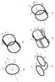
つぎに、本発明の第2の実施の形態のMRI装置の受信コイル14について図4を用いて説明する。第2の実施の形態の受信コイル14は、位相エンコード方向をXYZのいずれにも設定可能であり、位相エンコード方向に制限がない。受信コイル14以外の構成は、第1の実施の形態と同様である。 Next, the receiving
第2の実施の形態では、図4(a)〜(e)に示した5つの受信コイルを同一空間に組み合わせて配置することにより受信コイル14を構成する。図4(a)のコイル42は、ソレノイド型コイルであり、主にY軸方向に絶対値感度を有し、この方向に高い中心感度が得られる。図4(b)のコイル40は、サドル型コイルであり、ソレノイド型コイル42に対して直交するX軸方向に絶対値感度を有し、この方向に高い中心感度が得られる。これらコイル40,42は、感度の位相成分に分布がなく一様である。一方、図4(c)のコイル41は、X軸方向に対称なループ413、414を有し、感度の位相成分がX軸方向について分布がある。図4(d)のコイル43は、2つの8の字型コイル431、432をZ軸方向に配置し、連結したものであり、Z軸方向に位相差分布がある。図4(e)のコイル44は、Y軸方向に対称なループ441、442を有し、Y軸方向に位相差分布がある。 In 2nd Embodiment, the receiving
これら5つのコイル40〜44を同一空間に組み合わせて配置し、受信コイル14を構成することにより、X軸方向の位相エンコード方向とする場合には、受信コイル40、42で高い中心感度を取得し、同時に受信コイル41でX軸方向に位相差を持った位相分布を取得し、パラレルMRIを行うことができる。また、位相エンコード方向をY軸とする場合は、受信コイル40、42で高い中心感度を取得し、同時に受信コイル44でY軸方向に位相差を持った位相分布を取得し、パラレルMRIを行うことができる。さらに、位相エンコード方向をZ軸とした場合は、受信コイル40、42で高い中心感度を取得し、同時に受信コイル43でZ軸方向に位相差を持った位相分布を取得し、パラレルMRIを行うことができる。このように、図4(a)〜(e)の5つのコイル40〜44を組み合わせることにより、中心感度が高く、かつ、位相エンコード方向に制限のないパラレルMRIを実現できる。 When these five
図4(c)〜(e)の感度の位相成分に分布をもつ受信コイル41、43、44は、位相分布の変化が、+90°から−90°へと位相が所定の軸方向に1回生じるのみの1次的位相変化のコイルであるが、本発明は上記のような受信コイルに限られるものではない。例えば、図5(a)に示した受信コイル45は、図5(b)に示したように+90°から−90°へ、−90°から+90°へ、+90°から−90°へと、所定の軸方向に位相が3回変化する3次的位相変化を有するコイルである。この受信コイル45を、図4の受信コイル40〜44の全て、もしくはこれらの任意の一部と組み合わせて用いることにより、パラレルMRIを実現できる。 In the receiving coils 41, 43, and 44 having distributions in the phase components of sensitivity shown in FIGS. 4C to 4E, the phase distribution changes once in the predetermined axial direction from + 90 ° to −90 °. Although only a primary phase change coil is generated, the present invention is not limited to the receiving coil as described above. For example, the receiving
また、位相差をもった受信コイルを複数個オーバーラップさせて配置することにより、絶対値の感度分布を生じさせることもできる。例えば、図6(a)に示すように、X軸方向に位相差を有する3つの受信コイル461,462,463をZ軸方向に一部が重なり合うように配置することにより、Z軸方向に絶対値の感度分布を生じさせることができる。よって、図6(a)の受信コイルを、図4(c)の受信コイル41に代えて図4の他の受信コイル40、42、43、44の全て、もしくはこれらの一部と任意に組み合わせることにより、位相エンコード方向をX軸もしくはZ軸とするパラレルMRIを行うことができる。また、図6(b)のようにZ軸方向に位相差を有する3つの受信コイル471、472をY軸方向に一部が重なり合うように配置することにより、Y軸方向に絶対値の感度分布を生じさせることができる。よって、図6(b)の受信コイルを、図4(d)の受信コイル43に代えて図4の他の受信コイル40、41、42、44の全て、もしくはこれらの一部と任意に組み合わせることにより、位相エンコード方向をZ軸もしくはY軸とするパラレルMRIを行うことができる。 Further, by arranging a plurality of receiving coils having a phase difference so as to overlap each other, a sensitivity distribution of absolute values can be generated. For example, as shown in FIG. 6A, by arranging three receiving
また、図4(d)に用いた8の字型のコイルは、図7(a)のように所定の軸方向(Z軸方向)に配置して連結することにより、図7(b)のように配置した軸方向に沿って受信感度の位相成分に分布を生じさせることができる。したがって、図7(a)の受信コイルを、他の所望の絶対値成分感度分布を有するコイルと組み合わせ、図7(a)の受信コイルの軸方向(図7(a)のZ軸方向)を位相エンコード方向としたい方向に配置することにより、任意の方向を位相エンコード方向に設定してパラレルMRIを行うことが可能である。 Further, the 8-shaped coil used in FIG. 4D is arranged and connected in a predetermined axial direction (Z-axis direction) as shown in FIG. A distribution can be generated in the phase component of the reception sensitivity along the axial direction. Accordingly, the receiving coil in FIG. 7A is combined with another coil having a desired absolute value component sensitivity distribution, and the axial direction of the receiving coil in FIG. 7A (the Z-axis direction in FIG. 7A) is set. By arranging in the direction desired to be the phase encoding direction, it is possible to perform parallel MRI by setting an arbitrary direction as the phase encoding direction.
1・・・中央処理装置(CPU)、2・・・シーケンサ、3・・・送信系、4・・・傾斜磁場発生系、5・・・受信系、6・・・信号処理系、14・・・受信コイル、22・・・静磁場発生系、40・・・サドル型コイル、41、43、44・・・位相分布のあるコイル、42・・・ソレノイド型コイル。
DESCRIPTION OF SYMBOLS 1 ... Central processing unit (CPU), 2 ... Sequencer, 3 ... Transmission system, 4 ... Gradient magnetic field generation system, 5 ... Reception system, 6 ... Signal processing system, 14 ..Receiving coil, 22... Static magnetic field generation system, 40... Saddle type coil, 41, 43, 44... Coil with phase distribution, 42.
Claims (5)
Translated fromJapanese前記直交する3方向は、前記核磁気共鳴信号に位置情報をエンコードするための位相エンコード方向と周波数エンコード方向とを含み、
前記複数の受信コイルは、前記空間の撮像野に同時に配置され、前記核磁気共鳴信号を同時に受信する構成であり、
該複数の受信コイルのうち第1の受信コイルは、受信感度の絶対値成分の分布が、前記撮像野の位相エンコード方向について、両端部の方が中心部より高感度であり、かつ、受信感度の位相成分の分布が、前記撮像野の位相エンコード方向について、前記撮像野の中心に対して非対称な分布であり、
前記複数の受信コイルのうち第2の受信コイルは、受信感度の絶対値成分の分布が、前記撮像野の位相エンコード方向について、中心部の方が両端部よりも高感度であり、
前記第1の受信コイルの受信感度の位相成分の分布は、前記位相エンコード方向について、前記撮像野内で複数回変化していることを特徴とする磁気共鳴イメージング装置。A static magnetic field generation unit that generates a static magnetic field in a space in which the subject is arranged, a gradient magnetic field generation unit that applies a gradient magnetic field in each of three orthogonal directions of the space, and a high frequency that applies a high-frequency magnetic field pulse to the subject A magnetic field irradiator, a plurality of receiving coils for receiving nuclear magnetic resonance signals from the subject, and a signal received by the receiving coil are processed using the sensitivity distribution of the plurality of receiving coils to perform image reconstruction. A signal processing unit to perform,
The three orthogonal directions include a phase encoding direction and a frequency encoding direction for encoding position information in the nuclear magnetic resonance signal,
The plurality of receiving coils are simultaneously arranged in the imaging field of the space, and are configured to receive the nuclear magnetic resonance signals simultaneously.
The first receiving coil of the plurality of receiving coils is such that the distribution of the absolute value component of the receiving sensitivity is higher in sensitivity at both ends than in the center with respect to the phase encoding direction of the imaging field, and the receiving sensitivity. The phase component distribution is asymmetric with respect to the center of the imaging field in the phase encoding direction of the imaging field,
Second receiving coils of the plurality of receiving coils, the distribution of the absolute value component of the receiving sensitivity, the phase encoding direction of the imaging field,Ri sensitive der than both end portions toward the centerportion,
The distribution of the phase component of the receiving sensitivity of the first receiving coil changes a plurality of times in the imaging field in the phase encoding direction .
前記第1の受信コイルは、前記位相エンコード方向を設定可能な方向についてそれぞれ配置されていることを特徴とする磁気共鳴イメージング装置。The magnetic resonance imaging apparatus accordingto claim 1 , wherein the phase encoding direction can be set by selecting any one of a plurality of predetermined directions among the three orthogonal directions.
The magnetic resonance imaging apparatus according to claim 1, wherein the first receiving coils are arranged in directions in which the phase encoding direction can be set.
前記直交する3方向は、前記核磁気共鳴信号に位置情報をエンコードするための位相エンコード方向と周波数エンコード方向とを含み、
前記複数の受信コイルは、前記空間の撮像野に同時に配置され、前記核磁気共鳴信号を同時に受信する構成であり、
該複数の受信コイルのうち第1の受信コイルは、受信感度の絶対値成分の分布が、前記撮像野の位相エンコード方向について、両端部の方が中心部より高感度であり、かつ、受信感度の位相成分の分布が、前記撮像野の位相エンコード方向について、前記撮像野の中心に対して非対称な分布であり、
前記複数の受信コイルのうち第2の受信コイルは、受信感度の絶対値成分の分布が、前記撮像野の位相エンコード方向について、中心部の方が両端部よりも高感度であり、
前記位相エンコード方向は、前記直交する3方向のうちの2方向のいずれかを選択して設定可能であり、
前記第1の受信コイルは、前記2方向のいずれについても、前記受信感度の位相成分の分布が、前記撮像野の中心に対して非対称な分布であることを特徴とする磁気共鳴イメージング装置。A static magnetic field generation unit that generates a static magnetic field in a space in which the subject is arranged, a gradient magnetic field generation unit that applies a gradient magnetic field in each of three orthogonal directions of the space, and a high frequency that applies a high-frequency magnetic field pulse to the subject A magnetic field irradiator, a plurality of receiving coils for receiving nuclear magnetic resonance signals from the subject, and a signal received by the receiving coil are processed using the sensitivity distribution of the plurality of receiving coils to perform image reconstruction. A signal processing unit to perform,
The three orthogonal directions include a phase encoding direction and a frequency encoding direction for encoding position information in the nuclear magnetic resonance signal,
The plurality of receiving coils are simultaneously arranged in the imaging field of the space, and are configured to receive the nuclear magnetic resonance signals simultaneously.
The first receiving coil of the plurality of receiving coils is such that the distribution of the absolute value component of the receiving sensitivity is higher in sensitivity at both ends than in the center with respect to the phase encoding direction of the imaging field, and the receiving sensitivity. The phase component distribution is asymmetric with respect to the center of the imaging field in the phase encoding direction of the imaging field,
Second receiving coils of the plurality of receiving coils, the distribution of the absolute value component of the receiving sensitivity, the phase encoding direction of the imaging field,Ri sensitive der than both end portions toward the centerportion,
The phase encoding direction can be set by selecting any one of the two orthogonal directions.
In the magnetic resonance imaging apparatus,the first reception coil has a distribution of phase components of the reception sensitivity that is asymmetric with respect to the center of the imaging field in any of the two directions .
Priority Applications (1)
| Application Number | Priority Date | Filing Date | Title |
|---|---|---|---|
| JP2005151097AJP4817715B2 (en) | 2005-05-24 | 2005-05-24 | Magnetic resonance imaging system |
Applications Claiming Priority (1)
| Application Number | Priority Date | Filing Date | Title |
|---|---|---|---|
| JP2005151097AJP4817715B2 (en) | 2005-05-24 | 2005-05-24 | Magnetic resonance imaging system |
Publications (2)
| Publication Number | Publication Date |
|---|---|
| JP2006325737A JP2006325737A (en) | 2006-12-07 |
| JP4817715B2true JP4817715B2 (en) | 2011-11-16 |
Family
ID=37548083
Family Applications (1)
| Application Number | Title | Priority Date | Filing Date |
|---|---|---|---|
| JP2005151097AExpired - LifetimeJP4817715B2 (en) | 2005-05-24 | 2005-05-24 | Magnetic resonance imaging system |
Country Status (1)
| Country | Link |
|---|---|
| JP (1) | JP4817715B2 (en) |
Families Citing this family (1)
| Publication number | Priority date | Publication date | Assignee | Title |
|---|---|---|---|---|
| JP7608268B2 (en)* | 2021-05-20 | 2025-01-06 | 富士フイルム株式会社 | Magnetic resonance imaging device and sensitivity distribution calculation program |
Family Cites Families (6)
| Publication number | Priority date | Publication date | Assignee | Title |
|---|---|---|---|---|
| JP3342988B2 (en)* | 1995-06-29 | 2002-11-11 | ジーイー横河メディカルシステム株式会社 | Flexible coil |
| US6493572B1 (en)* | 1999-09-30 | 2002-12-10 | Toshiba America Mri, Inc. | Inherently de-coupled sandwiched solenoidal array coil |
| JP3992934B2 (en)* | 2001-02-23 | 2007-10-17 | 株式会社日立メディコ | Magnetic resonance imaging apparatus and method |
| JP4443079B2 (en)* | 2001-09-13 | 2010-03-31 | 株式会社日立メディコ | Magnetic resonance imaging apparatus and RF receiving coil for magnetic resonance imaging apparatus |
| US7221161B2 (en)* | 2003-01-21 | 2007-05-22 | General Electric Company | Coil arrays for parallel imaging in magnetic resonance imaging |
| JP2005040315A (en)* | 2003-07-22 | 2005-02-17 | Hitachi Medical Corp | Multiple rf receiving coil for magnetic resonance imaging device and magnetic resonance imaging device |
- 2005
- 2005-05-24JPJP2005151097Apatent/JP4817715B2/ennot_activeExpired - Lifetime
Also Published As
| Publication number | Publication date |
|---|---|
| JP2006325737A (en) | 2006-12-07 |
Similar Documents
| Publication | Publication Date | Title |
|---|---|---|
| EP1875862B1 (en) | Inspection equipment employing magnetic resonance | |
| NL1033706C2 (en) | SAR reduction in MR image with parallel RF transmission. | |
| US6937015B2 (en) | Method for optimizing the k-space trajectories in the location encoding of a magnetic resonance tomography apparatus | |
| US9664762B2 (en) | System and method for reduced field of view magnetic resonance imaging | |
| JP5498031B2 (en) | Magnetic resonance imaging system | |
| JP2014083445A (en) | Magnetic resonance imaging system, and magnetic resonance imaging method | |
| US10470685B2 (en) | Method and apparatus for capturing magnetic resonance image | |
| JP2010508054A (en) | MRIRF encoding using multiple transmit coils | |
| US8299793B2 (en) | Method and apparatus for improving 2D acceleration in MRI using a new coil array design | |
| CN111712719B (en) | Active B1+ shimming for transmit coils | |
| US10866294B2 (en) | Magnetic resonance imaging apparatus, multi-slice imaging method, and shimming value calculation apparatus | |
| JP2005087375A (en) | Magnetic resonance imaging apparatus and magnetic resonance image generation method | |
| US10156622B2 (en) | Method and apparatus for sectional optimization of radial MR pulse sequences | |
| JP5675044B2 (en) | Magnetic resonance imaging system | |
| JP2007111187A (en) | Rf coil and magnetic resonance imaging system | |
| JP4817715B2 (en) | Magnetic resonance imaging system | |
| US7307419B2 (en) | Method and system for spatial-spectral excitation by parallel RF transmission | |
| US9810757B2 (en) | High-speed magnetic resonance imaging method and apparatus | |
| JP7383386B2 (en) | magnetic resonance imaging device | |
| JP5159099B2 (en) | Magnetic resonance imaging system | |
| JP2004202047A (en) | Receiving coil for mri, and mri system | |
| JP6687375B2 (en) | RF coil and magnetic resonance imaging apparatus | |
| JP7408351B2 (en) | magnetic resonance imaging device | |
| JP2024017322A (en) | Magnetic resonance imaging device, magnetic resonance imaging method and program | |
| US20060132132A1 (en) | Method and system for MR scan acceleration using selective excitation and parallel transmission |
Legal Events
| Date | Code | Title | Description |
|---|---|---|---|
| A621 | Written request for application examination | Free format text:JAPANESE INTERMEDIATE CODE: A621 Effective date:20080501 | |
| A977 | Report on retrieval | Free format text:JAPANESE INTERMEDIATE CODE: A971007 Effective date:20101104 | |
| A131 | Notification of reasons for refusal | Free format text:JAPANESE INTERMEDIATE CODE: A131 Effective date:20101109 | |
| A521 | Request for written amendment filed | Free format text:JAPANESE INTERMEDIATE CODE: A523 Effective date:20110106 | |
| A131 | Notification of reasons for refusal | Free format text:JAPANESE INTERMEDIATE CODE: A131 Effective date:20110426 | |
| A521 | Request for written amendment filed | Free format text:JAPANESE INTERMEDIATE CODE: A523 Effective date:20110603 | |
| TRDD | Decision of grant or rejection written | ||
| A01 | Written decision to grant a patent or to grant a registration (utility model) | Free format text:JAPANESE INTERMEDIATE CODE: A01 Effective date:20110830 | |
| A01 | Written decision to grant a patent or to grant a registration (utility model) | Free format text:JAPANESE INTERMEDIATE CODE: A01 | |
| A61 | First payment of annual fees (during grant procedure) | Free format text:JAPANESE INTERMEDIATE CODE: A61 Effective date:20110830 | |
| FPAY | Renewal fee payment (event date is renewal date of database) | Free format text:PAYMENT UNTIL: 20140909 Year of fee payment:3 | |
| R150 | Certificate of patent or registration of utility model | Ref document number:4817715 Country of ref document:JP Free format text:JAPANESE INTERMEDIATE CODE: R150 Free format text:JAPANESE INTERMEDIATE CODE: R150 | |
| S111 | Request for change of ownership or part of ownership | Free format text:JAPANESE INTERMEDIATE CODE: R313111 | |
| S533 | Written request for registration of change of name | Free format text:JAPANESE INTERMEDIATE CODE: R313533 | |
| R350 | Written notification of registration of transfer | Free format text:JAPANESE INTERMEDIATE CODE: R350 | |
| S111 | Request for change of ownership or part of ownership | Free format text:JAPANESE INTERMEDIATE CODE: R313111 | |
| R350 | Written notification of registration of transfer | Free format text:JAPANESE INTERMEDIATE CODE: R350 | |
| R250 | Receipt of annual fees | Free format text:JAPANESE INTERMEDIATE CODE: R250 | |
| R250 | Receipt of annual fees | Free format text:JAPANESE INTERMEDIATE CODE: R250 | |
| S111 | Request for change of ownership or part of ownership | Free format text:JAPANESE INTERMEDIATE CODE: R313111 | |
| R250 | Receipt of annual fees | Free format text:JAPANESE INTERMEDIATE CODE: R250 | |
| R350 | Written notification of registration of transfer | Free format text:JAPANESE INTERMEDIATE CODE: R350 | |
| EXPY | Cancellation because of completion of term |