JP4817676B2 - Anchor elements for dynamic stabilization of vertebrae or bones and stabilization devices using the anchor elements - Google Patents
Anchor elements for dynamic stabilization of vertebrae or bones and stabilization devices using the anchor elementsDownload PDFInfo
- Publication number
- JP4817676B2 JP4817676B2JP2005057591AJP2005057591AJP4817676B2JP 4817676 B2JP4817676 B2JP 4817676B2JP 2005057591 AJP2005057591 AJP 2005057591AJP 2005057591 AJP2005057591 AJP 2005057591AJP 4817676 B2JP4817676 B2JP 4817676B2
- Authority
- JP
- Japan
- Prior art keywords
- rod
- bone
- anchor
- head
- bearing
- Prior art date
- Legal status (The legal status is an assumption and is not a legal conclusion. Google has not performed a legal analysis and makes no representation as to the accuracy of the status listed.)
- Expired - Fee Related
Links
- 210000000988bone and boneAnatomy0.000titleclaimsdescription52
- 230000006641stabilisationEffects0.000titledescription15
- 238000011105stabilizationMethods0.000titledescription15
- 239000000463materialSubstances0.000claimsdescription8
- 230000000087stabilizing effectEffects0.000claimsdescription6
- 239000004698PolyethyleneSubstances0.000claimsdescription5
- 229920000573polyethylenePolymers0.000claimsdescription5
- 229920003023plasticPolymers0.000claimsdescription4
- 239000004033plasticSubstances0.000claimsdescription4
- -1polyethylenePolymers0.000claimsdescription3
- 239000003381stabilizerSubstances0.000claimsdescription2
- 238000004873anchoringMethods0.000claims1
- CNQCVBJFEGMYDW-UHFFFAOYSA-Nlawrencium atomChemical compound[Lr]CNQCVBJFEGMYDW-UHFFFAOYSA-N0.000description7
- 239000004699Ultra-high molecular weight polyethyleneSubstances0.000description6
- 229920000785ultra high molecular weight polyethylenePolymers0.000description6
- 230000009286beneficial effectEffects0.000description4
- VGGSQFUCUMXWEO-UHFFFAOYSA-NEtheneChemical compoundC=CVGGSQFUCUMXWEO-UHFFFAOYSA-N0.000description2
- 238000005452bendingMethods0.000description2
- 238000004132cross linkingMethods0.000description2
- 229920001903high density polyethylenePolymers0.000description2
- 239000004700high-density polyethyleneSubstances0.000description2
- 229920000092linear low density polyethylenePolymers0.000description2
- 239000004707linear low-density polyethyleneSubstances0.000description2
- 230000007774longtermEffects0.000description2
- 229920001684low density polyethylenePolymers0.000description2
- 239000004702low-density polyethyleneSubstances0.000description2
- RTAQQCXQSZGOHL-UHFFFAOYSA-NTitaniumChemical compound[Ti]RTAQQCXQSZGOHL-UHFFFAOYSA-N0.000description1
- 230000004323axial lengthEffects0.000description1
- 239000000560biocompatible materialSubstances0.000description1
- 230000002950deficientEffects0.000description1
- 230000000694effectsEffects0.000description1
- 238000007373indentationMethods0.000description1
- 238000000034methodMethods0.000description1
- ORQBXQOJMQIAOY-UHFFFAOYSA-NnobeliumChemical compound[No]ORQBXQOJMQIAOY-UHFFFAOYSA-N0.000description1
- 238000000926separation methodMethods0.000description1
- 238000001356surgical procedureMethods0.000description1
- 229910052719titaniumInorganic materials0.000description1
- 239000010936titaniumSubstances0.000description1
- 230000009466transformationEffects0.000description1
Images


Classifications
- A—HUMAN NECESSITIES
- A61—MEDICAL OR VETERINARY SCIENCE; HYGIENE
- A61B—DIAGNOSIS; SURGERY; IDENTIFICATION
- A61B17/00—Surgical instruments, devices or methods
- A61B17/56—Surgical instruments or methods for treatment of bones or joints; Devices specially adapted therefor
- A61B17/58—Surgical instruments or methods for treatment of bones or joints; Devices specially adapted therefor for osteosynthesis, e.g. bone plates, screws or setting implements
- A61B17/68—Internal fixation devices, including fasteners and spinal fixators, even if a part thereof projects from the skin
- A61B17/70—Spinal positioners or stabilisers, e.g. stabilisers comprising fluid filler in an implant
- A61B17/7001—Screws or hooks combined with longitudinal elements which do not contact vertebrae
- A61B17/7035—Screws or hooks, wherein a rod-clamping part and a bone-anchoring part can pivot relative to each other
- A—HUMAN NECESSITIES
- A61—MEDICAL OR VETERINARY SCIENCE; HYGIENE
- A61B—DIAGNOSIS; SURGERY; IDENTIFICATION
- A61B17/00—Surgical instruments, devices or methods
- A61B17/56—Surgical instruments or methods for treatment of bones or joints; Devices specially adapted therefor
- A61B17/58—Surgical instruments or methods for treatment of bones or joints; Devices specially adapted therefor for osteosynthesis, e.g. bone plates, screws or setting implements
- A61B17/68—Internal fixation devices, including fasteners and spinal fixators, even if a part thereof projects from the skin
- A61B17/70—Spinal positioners or stabilisers, e.g. stabilisers comprising fluid filler in an implant
- A61B17/7001—Screws or hooks combined with longitudinal elements which do not contact vertebrae
- A61B17/7002—Longitudinal elements, e.g. rods
- A61B17/701—Longitudinal elements with a non-circular, e.g. rectangular, cross-section
- A—HUMAN NECESSITIES
- A61—MEDICAL OR VETERINARY SCIENCE; HYGIENE
- A61B—DIAGNOSIS; SURGERY; IDENTIFICATION
- A61B17/00—Surgical instruments, devices or methods
- A61B17/56—Surgical instruments or methods for treatment of bones or joints; Devices specially adapted therefor
- A61B17/58—Surgical instruments or methods for treatment of bones or joints; Devices specially adapted therefor for osteosynthesis, e.g. bone plates, screws or setting implements
- A61B17/68—Internal fixation devices, including fasteners and spinal fixators, even if a part thereof projects from the skin
- A61B17/70—Spinal positioners or stabilisers, e.g. stabilisers comprising fluid filler in an implant
- A61B17/7001—Screws or hooks combined with longitudinal elements which do not contact vertebrae
- A61B17/7002—Longitudinal elements, e.g. rods
- A61B17/7011—Longitudinal element being non-straight, e.g. curved, angled or branched
- A—HUMAN NECESSITIES
- A61—MEDICAL OR VETERINARY SCIENCE; HYGIENE
- A61B—DIAGNOSIS; SURGERY; IDENTIFICATION
- A61B17/00—Surgical instruments, devices or methods
- A61B17/56—Surgical instruments or methods for treatment of bones or joints; Devices specially adapted therefor
- A61B17/58—Surgical instruments or methods for treatment of bones or joints; Devices specially adapted therefor for osteosynthesis, e.g. bone plates, screws or setting implements
- A61B17/68—Internal fixation devices, including fasteners and spinal fixators, even if a part thereof projects from the skin
- A61B17/70—Spinal positioners or stabilisers, e.g. stabilisers comprising fluid filler in an implant
- A61B17/7001—Screws or hooks combined with longitudinal elements which do not contact vertebrae
- A61B17/7032—Screws or hooks with U-shaped head or back through which longitudinal rods pass
- A—HUMAN NECESSITIES
- A61—MEDICAL OR VETERINARY SCIENCE; HYGIENE
- A61B—DIAGNOSIS; SURGERY; IDENTIFICATION
- A61B17/00—Surgical instruments, devices or methods
- A61B17/56—Surgical instruments or methods for treatment of bones or joints; Devices specially adapted therefor
- A61B17/58—Surgical instruments or methods for treatment of bones or joints; Devices specially adapted therefor for osteosynthesis, e.g. bone plates, screws or setting implements
- A61B17/68—Internal fixation devices, including fasteners and spinal fixators, even if a part thereof projects from the skin
- A61B17/70—Spinal positioners or stabilisers, e.g. stabilisers comprising fluid filler in an implant
- A61B17/7001—Screws or hooks combined with longitudinal elements which do not contact vertebrae
- A61B17/7035—Screws or hooks, wherein a rod-clamping part and a bone-anchoring part can pivot relative to each other
- A61B17/7037—Screws or hooks, wherein a rod-clamping part and a bone-anchoring part can pivot relative to each other wherein pivoting is blocked when the rod is clamped
- A—HUMAN NECESSITIES
- A61—MEDICAL OR VETERINARY SCIENCE; HYGIENE
- A61B—DIAGNOSIS; SURGERY; IDENTIFICATION
- A61B17/00—Surgical instruments, devices or methods
- A61B17/56—Surgical instruments or methods for treatment of bones or joints; Devices specially adapted therefor
- A61B17/58—Surgical instruments or methods for treatment of bones or joints; Devices specially adapted therefor for osteosynthesis, e.g. bone plates, screws or setting implements
- A61B17/68—Internal fixation devices, including fasteners and spinal fixators, even if a part thereof projects from the skin
- A61B17/70—Spinal positioners or stabilisers, e.g. stabilisers comprising fluid filler in an implant
- A61B17/7001—Screws or hooks combined with longitudinal elements which do not contact vertebrae
- A61B17/7002—Longitudinal elements, e.g. rods
- A61B17/7019—Longitudinal elements having flexible parts, or parts connected together, such that after implantation the elements can move relative to each other
- A61B17/7026—Longitudinal elements having flexible parts, or parts connected together, such that after implantation the elements can move relative to each other with a part that is flexible due to its form
Landscapes
- Health & Medical Sciences (AREA)
- Orthopedic Medicine & Surgery (AREA)
- Life Sciences & Earth Sciences (AREA)
- Neurology (AREA)
- Surgery (AREA)
- Heart & Thoracic Surgery (AREA)
- Engineering & Computer Science (AREA)
- Biomedical Technology (AREA)
- Nuclear Medicine, Radiotherapy & Molecular Imaging (AREA)
- Medical Informatics (AREA)
- Molecular Biology (AREA)
- Animal Behavior & Ethology (AREA)
- General Health & Medical Sciences (AREA)
- Public Health (AREA)
- Veterinary Medicine (AREA)
- Surgical Instruments (AREA)
- Prostheses (AREA)
Description
Translated fromJapanese本発明は、アンカー要素および当該アンカー要素を使用した椎骨または骨の動的安定化のための安定化器具に関する。 The present invention relates to an anchor element and a stabilizing device for dynamic stabilization of vertebrae or bones using the anchor element.
骨折を固定するためまたは脊柱を安定化するための、各々が骨および/または椎骨内に固定され、そして剛性ロッドによって相互に接続される少なくとも2本の骨ねじからなる剛性の固定器具および安定化器具は知られている。例えば、ヨーロッパ特許第0 483
242号から、このタイプの安定化器具として剛性ロッドと一緒に使用される特許請求項1のプリアンブルに従ったアンカー要素が知られている。相互に対して安定化されるべき骨の部分または椎骨の相対運動が望ましくない場合、例えば骨折または他の欠陥のある位置が存在する場合には、剛性システムが使用される。Rigid fixation device and stabilization consisting of at least two bone screws, each fixed in a bone and / or vertebra and connected to each other by a rigid rod, for fixing a fracture or stabilizing the spine The instrument is known. For example, European Patent 0 483
From 242 an anchor element according to the preamble of claim 1 is known which is used with a rigid rod as a stabilizer of this type. A rigid system is used when relative movement of the bone parts or vertebrae to be stabilized relative to each other is undesirable, for example when there is a fracture or other defective location.
ねじ要素およびロッドに接続するための受入れ部を備える多軸骨ねじの形状にある骨アンカー要素は米国特許第5,474,555号(特許文献1)から知られており、この場合は骨内に固定されるべきねじ要素はねじ要素と受入れ部との間の多少の運動が可能であるように受入れ部へ接続される。しかし、該特許に記載された解決策は制御された運動の可能性を備える安定化を可能にしない。 A bone anchor element in the form of a polyaxial bone screw with a receiving element for connection to a screw element and a rod is known from US Pat. No. 5,474,555, in this case intraosseous The screw element to be fastened to is connected to the receiving part so that some movement between the screw element and the receiving part is possible. However, the solution described in the patent does not allow stabilization with the possibility of controlled movement.
一定の適応、例えば椎間板が損傷している、または人工椎間板が存在する場合には、安定化されるべき椎骨の多少の制限された運動を可能にする安定化器具を有するのが望ましい。このタイプの動的安定化器具は、例えば米国特許第5,733,284号(特許文献2)から知られている。 In certain indications, such as when the disc is damaged or an artificial disc is present, it is desirable to have a stabilizing device that allows some limited movement of the vertebra to be stabilized. This type of dynamic stabilization device is known, for example, from US Pat. No. 5,733,284.
知られている安定化器具、特に動的器具には、ロッドがアンカー要素にトルクを加える可能性があるという固有の危険性が結び付いている。これは、アンカー要素のゆるみまたは骨からの分離を引き起こすことがある。 Known stabilization devices, in particular dynamic devices, are associated with the inherent risk that the rod may torque the anchor element. This can cause loosening of the anchor element or separation from the bone.
図9は、本出願人が知っている安定化器具200におけるねじ軸周囲でのトルクMの発生を示している。この図に示した安定化器具200では、2つの骨アンカー要素202、202’が相互に予め定められた曲げ弾性を備える湾曲したロッド201によって接続される。骨アンカー要素202、202’は骨ねじによって2つの隣接椎骨(図示していない)内にしっかりと取付けられる。図9は、2つの骨アンカー要素202、202’が力Fによって一緒に押し付けられる場合を示している。力Fによってロッド上には曲げモーメントが加えられ、これはねじ軸の周囲でトルクMを引き起こし、骨アンカー要素202、202’に作用する。これに対応して、2つの骨アンカー要素は力Fで引き離すように引っ張られ、ねじ軸の周囲で反対方向のトルクMが引き起こされる。
このため、本発明の目的は、作動中にアンカー要素がゆるんだり分離したりすることが防止される、アンカー要素および隣接する椎骨または骨の運動を安定化かつ制限するための動的安定化器具を提供することである。 Thus, it is an object of the present invention to provide a dynamic stabilization device for stabilizing and limiting movement of an anchor element and adjacent vertebrae or bones that prevents the anchor element from loosening or separating during operation. Is to provide.
この目的は、特許請求項1に従ったアンカー要素および特許請求項12に従った器具によって達成される。 This object is achieved by an anchor element according to claim 1 and an instrument according to
本発明のまた別の成果は、独立請求項に同定されている。 Further achievements of the invention are identified in the independent claims.
本発明は、ロッドに対して回転可能な、骨内に取付けられるアンカー要素のセクションの接続を作り出すことによって、アンカー要素に作用するトルクの作用下でアンカー要素がゆるんだり分離したりすることを効果的に防止できるという点で有益である。本安定化器具を使用すると、有益にも椎骨の動的安定化においてシャフトの回転がヘッドまたはロッドの固定から切り離される。 The present invention has the effect that the anchor element loosens and separates under the action of the torque acting on the anchor element by creating a connection of the section of the anchor element mounted in the bone that is rotatable relative to the rod. This is beneficial in that it can be prevented. Use of the present stabilizing device beneficially decouples shaft rotation from head or rod fixation in dynamic stabilization of the vertebra.
本発明のさらなる特徴および利点は、添付の図面に基づいた実施の形態の説明から明らかになる。 Further features and advantages of the present invention will become apparent from the description of embodiments based on the accompanying drawings.
第1の実施の形態
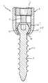
図1aおよびlbから明らかなように、第1の実施の形態に従うと、骨の部分または椎骨と、好ましくは長方形の断面を備えるロッド21とを接続させるためのアンカー要素1は、ねじ要素2、受入れ部3、受入れ部の中にねじ込まれる雌ねじ4および軸受部5を含む。First Embodiment As can be seen from FIGS. 1a and lb, according to a first embodiment, an anchor element 1 for connecting a bone part or vertebra and a
ねじ要素2は、骨または椎骨内に取付けるために球状セグメント形のヘッド6およびねじ切りシャフト7を含む。ねじ切りシャフト7の反対側では、ねじ要素2のヘッド6は平坦にされており、六角穴付きねじキーと係合するための窪み8を含む。 The
受入れ部3は、第1の端部9および第1の端部に対向する第2の端部10を備える本質的に円筒状の本体である。受入れ部は、その主軸と同軸性で伸びるボアホール11を含む。第1の端部9に隣接して、長方形の窪み12が2本の自由脚40、41を形成する前記窪みを備えるロッド21を受入れるために設けられている。窪みの幅はロッドの細い側の長さよりわずかに大きいが、他方窪みの深さはロッドの太い側の長さより大きい。雌ねじ山13は、第1の端部9に隣接する脚40、41の内側のボアホール11内に設けられる。ボアホールは、ねじ要素2のヘッド6の直径より大きい前記直径を備える第1の端部に隣接する第1のセクション内で本質的に一定の内径を有する。第1のセクションに隣接して、受入れ部3は、第2の端部に隣接して球状座部14が形成されるように、第1の端部9から第2の端部10へ向かって先細になるセクションを含む。第2の端部の側面上の開口部32はねじ要素2のねじ切りシャフト7の直径より大きい。 The
軸受部5は、平坦な前面15を備える円筒状セクションを含む。円筒状セクションの直径は、組立てられた状態でこのセクションが存在し、受入れ部3の第1のセクション内にプレス嵌めされるように選択される。さらに、軸受部5は球状座部14の形状に適合するセクション31の外形を備えるその円筒状セクションに隣接するボールソケット状セクション31を含む。軸受部5の内側では、ねじ要素2のヘッド6を受入れるために役立ち、さらにその球状形に適合する球状窪み17が設けられる。軸受部に対するねじ要素の回転運動および旋回運動の所望の抵抗性に依存して、窪み17の内径はねじ要素のヘッドの直径とほぼ同一であるか、それよりほんのわずかに大きい範囲内にある。平坦な前面15および窪み17内の端部から伸びるボアホール18が設けられており、その直径はねじ要素2を締付けるためにそれに通して六角穴付きねじキーを誘導することを可能にするが、ねじ要素2のヘッド6の直径よりは小さい。ボールソケット状のセクションには、窪み17で終了する同軸ボアホール19が設けられており、同軸ボアホール19の直径はねじ要素
2のヘッド6の直径より小さいが、ねじ山区域7の直径よりは大きい。図2から明らかなように、軸受部5は、ボールソケット状セクション内にスリット30を含み、ボールソケット状セクションは軸受部の弾性を増加させる前記スリット30を備える平坦な前面15とは反対側の軸受部の側面に隣接する。好ましくは、軸受部5は有益な滑り特性を備える生体適合性プラスチック材料から製造される。好ましくは、ポリエチレン(PE)が使用される。この状況では、様々な分子量を生じさせる様々な架橋度の、例えば50,000g/molまでの分子量を備えるLDPEおよびLLDPE、200,000g/molまでの分子量を備えるHDPEまたは約6,000,000g/molの分子量を備えるUHMWP(超高分子量ポリエチレン)などを使用できる。軸受部のための材料としては、長期的損耗率が低いためにUHMWPを使用するのが好ましい。The
雌ねじ4は六角穴付きねじキーが係合するための同軸窪み42を含む。 The internal thread 4 includes a
作動中には、ねじ要素2のヘッド6が最初に軸受部5の窪み17に挿入され、次にねじ要素2および軸受部5が一緒に受入れ部3に挿入される。この予備組立てに続いて、ねじ要素2が骨または椎骨内にねじ込まれる。次にロッド状要素21が受入れ部3内に配置されると、受入れ部3は自然にロッド状要素21に対して正確に整列する。続いて、ロッド状要素21は雌ねじ4によって受入れ部3に対して固定される。 In operation, the
上記に記載した方法に従うと、骨または椎骨内にしっかりとねじ込まれるねじ要素2とロッド状要素21との結合が形成されるが、このときねじ要素2のヘッド6は規定範囲の空間角度で回転可能であるように軸受部5に据えられる。空間角度の範囲は、一方ではねじ切りシャフト7の直径によって、そして他方では受入れ部3の第2の端部10の側面上の開口部32の直径または軸受部内の同軸ボアホール19の直径によって定められる。球状窪み17の直径およびヘッド6の直径が相互に対してどのように選択されるのかに依存して、ヘッドと軸受部の間で機能する様々な摩擦力を設定できるが、これは軸受部5の窪み17内のねじ要素2のヘッド6を回転または旋回させるために克服する必要がある力を設定できることを意味する。According to the method described above, a connection is formed between the
図3は、軸受部5’が第1の軸受要素5a’および第2の軸受要素5b’のツーピースの形状で設けられる、第1の実施の形態に従ったアンカー要素1の変形l’を示している。ツーピース軸受部5’は軸受部5と同様に設けられるが、その前面に対して平行にツーピースに切り込まれている。そこでこのツーピースは開口部19’を拡大する必要なくねじ要素2のヘッド6を窪み17’内に挿入することを可能にする。その結果として、軸受部5’はスリットを備えずに堅い材料から製造することができる。
第2の実施の形態
図4から7は、本発明の第2の実施の形態に従ったアンカー要素100を示している。第1の実施の形態の要素と同一である要素は、同じ参照番号で言及する。FIG. 3 shows a variant l ′ of the anchor element 1 according to the first embodiment, in which the
Second Embodiment FIGS. 4 to 7 show an
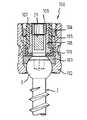
図4および5から最も明らかなように、第2の実施の形態に従ったアンカー要素100は、ねじ要素2、受入れ部102、圧力要素103、第1のリング104、第2のリング105、第1の軸受部106、第2の軸受部107、ロッド取付部108および雌ねじ109を含む。 4 and 5, the
第2の実施の形態に従ったアンカー要素100内のねじ要素2は、第1の実施の形態に従ったアンカー要素1のねじ要素2と同一である。 The
受入れ部102は、第1の端部112および第1の端部に対向する第2の端部113を備える本質的に円筒状の本体である。同軸ボアホール120は、受入れ部102の第1の端部112から第2の端部113へ伸びている。本質的にU字形の窪み140は第1の端
部112に隣接して設けられており、2つの自由脚114および115を形成する。雌ねじ山122は、自由脚114および115の内側で第1の端部112に隣接して設けられる。受入れ部102の第1の端部112に隣接するセクション内では、ボアホール120はねじ要素2のヘッド6の直径より大きい本質的に一定の直径を有する。第1のセクションに隣接していて受入れ部102の第2の端部へ伸びている第2のセクションでは、ボアホール120は第2の端部113に向かって先細になっている。球状セクション121は、その形状がねじ要素2のヘッド6の形状に適合する第2の端部113に隣接して設けられる。第2のセクション内のボアホールの直径は、第2の端部に隣接して、ねじ要素2のヘッド6の直径よりは小さいが、ねじ要素2のねじ切りシャフト7の直径よりは大きいように選択される。The receiving
第1のリング104は、その外側に雄ねじ山123を含み、雄ねじ山123は受入れ部102の自由脚114および115の内側で雌ねじ山122と一緒に機能する。リング104の1つの前面146上には、半径方向に伸びる窪み124が設けられており、この窪みには受入れ部102へ第1のリング104をねじ込むためのツールが係合できる。 The
第2のリング105は、第1の端部141に隣接する第1の内径を備える第1のセクションおよびそれにより形成される第2の内径を備える第2の端部142に隣接している第2の内径を備える第2のセクションを備える一定の外径を備える管状であるように設けられる。第2のリング105の外径はリングの全長に沿って一定であり、リング105をボアホール120内へ滑り入れることができるように受入れ部102の第1の端部112に隣接するセクション内のボアホール120の直径よりわずかに小さい。2つの自由脚114、115を形成する長方形の窪み143は、第1の端部141に隣接して設けられる。窪み143の幅は受入れ部102のU字形窪み140の幅に類似するが、これらの窪みに配置されるロッド21が予め定められた角度範囲、好ましくは約±10°の間で前後に旋回できるように、ロッドの長方形の断面の細い側より大きい。 The
圧力要素103は本質的に、その形状がねじ要素2のヘッド6の形状に適合するねじ頭に面する側に球状の窪み111を備える平坦な円筒状を有しており、そして圧力要素103には窪み111で終了してそれに通してねじ回しを誘導するのを可能にするために役立つ同軸ボアホール110が設けられる。圧力要素103の外径は、圧力要素103を受入れ部のボアホール内に滑り入れることができるように受入れ部102内のボアホール120の直径よりわずかに小さい。 The
第1および第2のリング104、105は、圧力要素103に力を加えるため、このため球状セクション121内にねじ要素2のヘッド6を固定するために役立つ。 The first and
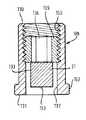
第1の軸受部106は、それに通してねじ回しを誘導するための同軸ボアホール135、および円周方向に沿って伸び、そして挿入された状態では圧力要素とは反対側に存在するリング状の突出部148を備える円板の形状を有する。リング状の突出部は、相互に対向する2つの長方形の窪み149を含む。 The
第2の軸受部107は。フランジ様張出し部151を備える管状セクションとして設けられるが、このとき管状セクションの直径は第1の軸受部106の直径より小さい。第2の軸受部107のフランジ様張出し部151の外径は、第1の軸受部106の直径と同一である。フランジ様張出し部151の側面に隣接して、相互に対向する2つの長方形の窪み150が設けられる。 The
挿入された状態では、第1および第2の軸受部106、107は、第1の軸受部106のリング状の突出部148が第2の軸受部107のフランジ様張出し部151に隣接する
ように同軸性で配列されるが、このとき2つの軸受部106、107内の長方形の窪み149、150は、ロッドを受入れるための2つの開口部が相互に対向していて軸受の内側で終了する前記開口部を備える2つの軸受部106、107によって形成された軸受内に形成されるように、各々相互に向かって整列される。組立てられた状態における窪み149、150により形成された開口部の幅は、これらの開口部に通して配置されたロッド21が予め定められた角度範囲、好ましくは約±10°の間で前後に旋回できるように設計されている。組立てられた状態での窪み149、150によって形成される開口部の高さは、ロッド21の対応する横断面よりわずかに大きい。軸受の外径は、軸受を第1および第2のクランプリング内にプレス嵌めすることをちょうど可能にする寸法取りされている。組立てられた状態では、フランジ様張出し部151は第2のリング105の肩147に寄り掛かっている。In the inserted state, the first and
好ましくは、第1および第2の軸受部106、107は有益な滑り特性を備える生体適合性プラスチック材料から製造される。好ましくは、ポリエチレン(PE)が使用される。この状況では、様々な分子量を生じさせる様々な架橋度の、例えば50,000g/molまでの分子量を備えるLDPEおよびLLDPE、200,000g/molまでの分子量を備えるHDPEまたは約6,000,000g/molの分子量を備えるUHMWP(超高分子量ポリエチレン)などを使用できる。軸受部のための材料としては、長期的損耗率が低いためにUHMWPを使用するのが好ましい。アンカー要素の残りの部分は、好ましくはチタンなどの有益な機械的特性を備える生体適合性材料から製造される。 Preferably, the first and
図5、6a、および6bから明らかなように、ロッド取付部108は第1の端部130および第2の端部131を備える円筒状の本体として設けられる。第1の端部130から第2の端部131へ伸びる連続的な同軸ボアホール132が設けられる。雌ねじ山155は第1の端部130に隣接するボアホール132内に設けられており、その雌ねじ山には雌ねじ109をねじ込むことができる。ロッド取付部108の外径は、第2の軸受部107の内径よりわずかに小さい。その第2の端部131では、ロッド取付部108はフランジ様張出し部152を含み、その外径は第1の軸受部106の内径よりわずかに小さい。相互に対向しており長方形の断面を有する2つの開口部133は、ロッド取付部108の側壁上に設けられる。開口部の幅Bはロッドの幅よりわずかに大きい。開口部の高さHはロッドの高さより大きい。 As is apparent from FIGS. 5, 6 a, and 6 b, the
雌ねじ109は、ロッド取付部108の雌ねじ山155と一緒に機能する雄ねじ山154を含む。雌ねじ109を通って伸びる同軸ボアホール134は、六角穴付きねじキーによって係合されるために適合する断面を有する。 The
図6aおよび6bから明らかなように、ロッド取付部108の雌ねじ山セクション155の軸の長さおよび開口部133の高さは、ロッドが開口部内で移動可能である1つの位置から開口部133の下方縁部153に押し付けられる位置へ移動可能であり、それにより雌ねじ109を締付けることによって所定位置に固定されるように選択される。 As is apparent from FIGS. 6a and 6b, the axial length of the
作動中には、アンカー要素を予備組立てするために、ねじ要素2はヘッド6が球状領域121の隣に存在するように最初はねじ切りシャフト7から先に受入れ部102に挿入される。続いて受入れ部102の第1の端部112から進めて、加圧要素103がヘッドに面する球状窪みを先頭にして111受入れ部102の同軸ボアホール120に挿入され、次に第1の軸受部100が同軸ボアホールを先頭にして受入れ部102内に、そして続いて不完全にねじ込まれている雌ねじ109を備えるロッド取付部108が第1の軸受部106内に配置される。その後、第2の軸受部107および第2のリング105が、受入れ部102の側壁と第2の軸受部106、107との間へ次々に挿入される。最後に、第1のリング104が、このように受入れ部102内へ挿入された要素が落下するのを防止す
るのに十分な程度にのみ離して受入れ部102内へねじ込まれる。これでアンカー要素100の予備組立てが完了する。In operation, to pre-assemble the anchor element, the
しかし代替法として、ロッド取付部108、第1および第2の軸受部106、107、第1および第2のリング104、105並びに雌ねじ109を最初に受入れ部の外側で組立て、その後に受入れ部に挿入することもできる。他のタイプの組立てもまた考えられるはずである。 However, as an alternative, the
作動中には、六角穴付きねじキーがボアホール134、132、135および110に通して誘導され、手術中に椎骨または骨内にねじ要素102をねじ込むために使用される。続いて、受入れ部102の側面から進んで、ロッドが受入れ部102の2つの自由脚114および115の間のロッド取付部108内の開口部133に通して、第1および第2の軸受部106および107内の開口部に通して、並びに第1のリング105内の窪みに通して滑り入れられる。続いて、第1のリング104を締付けることによって加圧要素103に力が加えられ、その結果として受入れ部102がねじ要素2に相対的な位置に固定される。次に雌ねじ109を挿入して締付けることによって、ロッドがロッド取付部108内の適切な位置に固定される
これはロッド状要素21と骨または椎骨との間の結合を生成し、このとき固定ロッド状要素21を備えるロッド取付部108は予め定められた角度範囲内で受入れ部102の主軸の周囲で回転することができる。角度範囲は、受入れ部102内のロッド21の寸法および窪み149の幅、開口部149の第1および第2の軸受部106内の長方形の窪み149、150の幅並びに第2のリング105内の窪み143の幅によって定められる。ロッド取付部108はロッド21と一緒に回転するが、他方軸受部106、107はプレス嵌めによって第1および第2のリング104、105内にしっかりと据えられる。受入れ部102に対するねじ軸の角度位置は固定されたままである。In operation, a hex socket screw key is guided through the
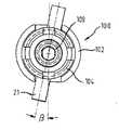
図7aおよび7bは、受入れ部102に対するロッド状要素21の2つの相違する限度角度位置α、βを示している。 FIGS. 7 a and 7 b show two different limit angular positions α, β of the rod-
ロッドがねじ要素に対する3つの回転自由度を有する第1の実施の形態に従ったアンカー要素1とは対照的に、第2の実施の形態に従ったアンカー要素100との接続は、たった1つの回転自由度しか有していない。
第3の実施の形態
本発明の第3の実施の形態に従うと、ロッドと骨または椎骨との間の回転可能な接続は、図8aに示したようにロッド407と受入れ部408との間およびねじ要素と受入れ部との間の角度が固定される多軸ねじと、ねじ切りシャフト412が回転可能であるようにねじ要素のヘッド401がねじ切りシャフト412へ接続されるツーピースねじ切りシャフト400と、を使用することによって作り出される。図8aに示したように、多軸ねじは受入れ部408、加圧要素409、雌ねじ410、および雄ねじ411を含む。In contrast to the anchor element 1 according to the first embodiment in which the rod has three rotational degrees of freedom relative to the screw element, the connection with the
Third Embodiment According to a third embodiment of the present invention, the rotatable connection between the rod and the bone or vertebra is between the
図8bから明らかなように、ねじ要素100のヘッド401は円筒状ネック403を備える球状セグメント形のヘッドセクション402からなる。さらに、ピン404がネック403の側面に設けられるが、このピンはばね力に逆らってネック403内へその長手軸に沿って押し込むことができる。 As can be seen from FIG. 8 b, the
ねじ要素400のヘッド401に面する側では、ねじ切りシャフト412はネック403が係合する同軸窪み405を含む。長手穴406は、ピン404が係合するこの窪み405の側壁に設けられる。 On the side of the
作動中には、ピンはネック403をねじ切りシャフト412の窪み405に滑り入れる
ことができる程度にネック内へ押し込まれる。ネック403は次に、ピン404がバネ力の外向きの圧力下で窪み405の壁の長手穴406に係合するように窪み405内に滑り入れられる。これはねじ要素100のヘッド401とねじ切りシャフト412との接続を生じさせ、このときヘッド401はねじ要素のねじ切りシャフト412に対して同軸性で回転することができ、ねじ要素のねじ切りシャフト412は長手穴406の長さによって予め定められた角度範囲の間で相互に対して同軸で回転することができる。In operation, the pin is pushed into the neck to such an extent that the
ねじ要素400は、次に受入れ部408内に挿入され、骨の中にねじ込まれる。続いて、受入れ部に対するねじ要素の位置が固定され、そしてロッド407が知られている方法で挿入かつ固定される。 The
第2の実施の形態に類似して、第3の実施の形態に従ったアンカー要素への接続は1つの回転自由度を有する。 Similar to the second embodiment, the connection to the anchor element according to the third embodiment has one degree of freedom of rotation.
図8cに示した第3の実施の形態の変形では、骨アンカー要素420は単軸ねじの形状で設けられるが、このとき受入れ部421はツーピースねじ要素のヘッドにしっかりと接続される、またはその一体部品である。他のすべての点において、骨アンカー要素420は上記に記載の第3の実施の形態と同様に設けられる。 In a variant of the third embodiment shown in FIG. 8c, the
上記に記載の実施の形態の変形は可能なはずである。 Variations of the above described embodiment should be possible.
第1の実施の形態に従ったアンカー要素の開口部19は、ヘッド6の直径よりは小さいがねじ山セクション7の直径よりは大きい直径を有すると記載した。しかし、開口部19の直径は、組立て中に開口部19を通してねじ切りシャフトを誘導する必要がないようにねじ要素がツーピースで設けられることを前提に、ねじ山セクション7の直径より小さくてもよい。さらにまた、ねじ要素を開口部に通してねじ込むことができるような開口部を設けることも可能なはずである。 The
第1の実施の形態に従ったアンカー要素では、非球状であるがねじ軸に対して回転可能な対称性の形状を有するヘッドは、受入れ部に対するねじ要素の回転運動を1つの自由度へ制限することができる。第1の実施の形態に従った軸受部5は、使用される材料の弾性がスリット20の不在下でねじ要素2のヘッド6の挿入を可能にすることを前提に、必ずしも1つもしくは数個のスリット20を含む必要はない。 In the anchor element according to the first embodiment, the non-spherical but symmetrical head that is rotatable with respect to the screw axis limits the rotational movement of the screw element relative to the receiving part to one degree of freedom. can do. One or several bearing
第2の実施の形態に従った受入れ部102の第2のセクション内のボアホール120の直径は、第2の端部113に隣接する領域ではねじ要素2のねじ切りシャフト7の直径より大きいと記載した。しかし、第2の端部に隣接するボアホール120の直径は、ねじ要素がボアホールに通してねじ込まれるように寸法取りすることもできる。あるいはマルチピースねじ要素の場合には、ボアホールの直径がねじ切りシャフト7の直径より小さくてもよく、この場合にはねじ切りシャフト7がボアホール120に通して誘導される必要はなく、むしろ受入れ部内に存在するヘッドへ外側から接続される。 The diameter of the
さらに、第1の軸受部106にはまた突出部148が設けられなくてもよい。 Further, the
第2の実施の形態に従った取付部分100は、受入れ部102がねじ要素2にしっかりと接続される、またはその一体部品である単軸ねじの形状で設けることができる。 The
上記のすべてのアンカー要素においては、ねじ要素によって取付ける代わりに、骨または椎骨内への、例えばフックによる取付などの相違するタイプの取付けを設けることができる。 In all the anchor elements mentioned above, instead of being attached by screw elements, different types of attachments can be provided in the bone or vertebra, for example by means of hooks.
本発明の第1および第2の実施の形態に従った骨アンカー要素は、正方形の断面を備えるロッド状要素について記載した。ロッドを受入れるための窪みおよびボアホールを適正に変形することによって、これらの骨アンカー要素はさらにまた円形もしくはいずれか他の断面を備えるロッド状要素の使用に適合することができる。同様に、第3の実施の形態に従った骨アンカー要素は、長方形またはいずれか他の断面を備えるロッド状要素とともに使用するために変形することもできる。 The bone anchor elements according to the first and second embodiments of the invention have been described for rod-like elements with a square cross section. By appropriately deforming the recesses and boreholes for receiving the rods, these bone anchor elements can also be adapted for use with rod-like elements with a circular or any other cross section. Similarly, the bone anchor element according to the third embodiment can also be deformed for use with rod-like elements with a rectangular or any other cross-section.
第3の実施の形態に関しては、ピン404をばね力に逆らってネック403内へ押し込むことができると記載した。しかし、ピン404はネック403または422内の穴の中へ圧力嵌めによって挿入し、それによりネック403または422へしっかりと接続することもできる。この場合、作動中には、ネックを最初はピンを付けずに窪み405内へ挿入し、そして次にネックの穴の中へ長手穴406に通してピンを挿入しなければならない。さらにまた、ピンが雄ねじ山を有し、ネックの穴の中に設けられた雌ねじ山にねじ込めるようにピンおよびネックを設けることもまた可能なはずである。ねじ山401とねじ区域402との多数のさらなる回転接続もまた可能なはずである。 With respect to the third embodiment, it has been described that the
本発明に従った骨または椎骨を動的安定化するための安定化器具は、図9に示した知られている安定化器具に類似して、ロッド状要素に接続された少なくとも2つの骨アンカー要素からなるが、それらのうちの少なくとも1つは第1から第3の実施の形態に従った骨アンカー要素である。 A stabilization device for dynamic stabilization of bone or vertebrae according to the present invention is similar to the known stabilization device shown in FIG. 9, at least two bone anchors connected to a rod-like element. Consisting of elements, at least one of which is a bone anchor element according to the first to third embodiments.
Claims (9)
Translated fromJapanese骨または椎骨内に取付けるべきシャフト(7)および前記シャフトの基端側に設けられた球状セグメント形のヘッド(6)を備える骨アンカー要素(2)と、
前記シャフト(7)に接続され、ロッド状要素(21)を受入れるための受入れ部(3)と、
前記ロッド状要素(21)を押し下げることにより前記受入れ部(3)内に前記ロッド状要素(21)を固定するための固定器具(4)と、
前記受入れ部(3)内の前記ロッド状要素(21)が固定される位置よりも低い位置で前記受入れ部(3)の内側ボアホール(11)に嵌められる軸受要素(5、5’)と、を備え、前記軸受要素(5、5’)の内面が前記ヘッド(6)を受入れ、
前記ロッド状要素(21)が前記受入れ部(3)に固定された状態では、前記骨アンカー要素(2)が前記ロッド状要素(21)に対して回転可能となるように、前記骨アンカー要素(2)がその頭部(6)で前記軸受要素(5、5’)の内面によって保持される、アンカー要素。An anchor element (1, 1') for mounting a rod-like element (21, 407) in a bone or vertebra,
A boneanchor element (2) comprising a shaft (7) to be mounted in a bone or vertebraand a spherical segment shaped head (6) provided on the proximal side of said shaft ;
Connected to said shaft(7), receiving portion for receiving the rod-shaped element(2 1) and(3),
The receiving unitby pushing down the rod-shaped element (21) and(3) the rod-like element in the (21) retainer for fixing the(4),
A bearing element (5, 5 ') fitted into the inner bore hole (11) of the receiving part (3) at a position lower than the position where the rod-shaped element (21) in the receiving part (3) is fixed ; the Beiexample, the inner surface of the bearing element (5, 5 ') is accepted and the head (6),
Wherein in the state where the rod-shaped element (21) isfixed to thefront Symbol receiving unit(3),such thatthe bone anchor element (2)isrotatable with respect to the rod-shaped element(21),said bone Anchor element, wherein the anchor element (2) is held at its head (6) by the inner surface of the bearing element (5, 5 ') .
骨または椎骨内に取付けるべきシャフト(7)および前記シャフトの基端側に設けられたヘッド(6)を備える骨アンカー要素(2)と、
前記ヘッド(6)に固定され、ロッド状要素(21)を受入れるための受入れ部(102)と、
前記受入れ部のボアホール(120)内に嵌めこまれ、軸受面を含む内面を有する軸受要素(106、107)と、
前記ロッド状要素(21)が固定されるロッド取付部(108)と、を備え、前記ロッド取付部(108)が前記軸受面によって前記軸受要素(106、107)に対して回転可能であるように保持され、
前記ロッド状要素(21)は、前記ロッド状要素(21)の長手方向が前記ロッド取付部(108)の回転軸と交差するように、前記前記ロッド取付部(108)に固定される、アンカー要素(100)。An anchor element (100) for mounting a rod-like element (21) in a bone or vertebra, comprising:
A bone anchor element (2) comprising a shaft (7) to be mounted in a bone or vertebra and a head (6) provided on the proximal side of said shaft ;
A receiving portion (102) fixed to the head (6) for receiving the rod-shaped element (21);
A bearing element (106, 107) fitted in the borehole (120) of the receiving portion and having an inner surface including a bearing surface;
A rod mounting portion (108) to which the rod-shaped element (21) is fixed, and the rod mounting portion (108) is rotatable with respect to the bearing element (106, 107) by the bearing surface. Held in
The rod-shaped element (21) is an anchor fixed to the rod mounting portion (108) such that the longitudinal direction of the rod-shaped element (21) intersects the rotation axis of the rod mounting portion (108). Element (100).
受入れ部(102)内のボアホール(120)の1つの端部に隣接して骨アンカー要素(2)の球状セグメント形のヘッド(6)を受入れるための球状座部(121)が設けられており、
受入れ部(102)内のボアホール(120)の他方の端に隣接して相互に対向する2つの窪み(140)が設けられており、これらが2つの自由脚(114、115)を形成しており、
ねじ山(122)が自由脚(114、115)の内側においてボアホール(120)内に設けられており、そのねじ山に、外周に雄ねじが形成されたリング状要素(104)がねじ込まれることにより、圧力要素(103)に力が加えられ、この力によって、受入れ部(102)に対して骨アンカー要素(2)が予め定められた角度位置で固定されるように、圧力要素(103)の圧力が骨アンカー要素(2)のヘッド(6)に作用し、このとき、
軸受要素(106、107)がリング状要素(104)の内側においてボアホール(120)内に存在する、アンカー要素。Provided in the form of multi-axial screw having a shaft (7) and the bone anchor element consisting of a spherical segment-shaped head (6)(2), an anchor element according to claim2 (100),
A spherical seat (121) for receiving a spherical segment-shaped head (6) of the bone anchor element (2) is provided adjacent one end ofthe borehole (120 )in the receiving part (102). ,
Two recesses (140) facing each other are provided adjacent to the other end ofthe borehole (120 )in the receiving part (102), and these form two free legs (114, 115). And
Thread (122) is providedin Oite borehole (120) in the inner side of the free legs (114, 115),on thethread, a ring-shaped elementformed with a male (104)is screwedon the outer peripheryby a force is applied to the pressure element (103), by the force, such that the bone anchor element (2) isfixed at a predetermined angular positionrelative to the receiving portion (102),the pressure element ( 103) acts on the head (6) of the bone anchor element (2) ,
Bearing element (106, 107) is presentin Oite borehole (120) inside the ring-shaped element (104), the anchor element.
骨または椎骨内に取付けるべきシャフト(412)、および、前記シャフトの基端側に設けられ前記シャフトとは別個の部材として設けられたヘッドを備える骨アンカー要素と、
前記アンカー要素に接続および固定され、ロッド状要素(407)を受入れるための受入れ部(408、421)と、を備えており、
前記ヘッドおよび前記受入れ部(408)が互いに固定されているか、または、前記ヘッドおよび前記受入れ部(421)が一体として形成されており、前記ヘッドおよび前記シャフトは、予め定められた角度内で前記シャフト(421)の中心軸を中心として互いに対して回転可能である、アンカー要素。An anchor element( 415, 420) for mounting a rod-like element( 407) in a bone or vertebra,
A boneanchor element comprising a shaft (412) to be mounted in a bone or vertebra, and a head provided on a proximal side of the shaft and provided as a separate member from the shaft ;
Which is connectedand fixed to theanchor element comprises receiving portion for receiving the rod-shaped element(4 07)and(408,421), and
The head and the receiving portion (408) are fixed to each other, or the head and the receiving portion (421) are integrally formed, and the head and the shaft are within a predetermined angle. Anchor elementsthat are rotatable relative to each other about the central axis of the shaft (421) .
少なくとも1つのアンカー要素が、請求項1〜8のいずれか1項に記載のアンカー要素である、安定化器具。A stabilizing device (200) comprising at least two anchor elements (202, 202 ') and a rod-like element (201) connecting them, wherein
At least one anchor element, an anchor element according to any one of claims1-8, stabilizer instrument.
Applications Claiming Priority (4)
| Application Number | Priority Date | Filing Date | Title |
|---|---|---|---|
| US55000804P | 2004-03-03 | 2004-03-03 | |
| US60/550008 | 2004-03-03 | ||
| DE102004010380.1 | 2004-03-03 | ||
| DE102004010380ADE102004010380A1 (en) | 2004-03-03 | 2004-03-03 | Anchoring element and stabilizing device for the dynamic stabilization of vertebrae or bones with such an anchoring element |
Publications (2)
| Publication Number | Publication Date |
|---|---|
| JP2005246061A JP2005246061A (en) | 2005-09-15 |
| JP4817676B2true JP4817676B2 (en) | 2011-11-16 |
Family
ID=34877306
Family Applications (1)
| Application Number | Title | Priority Date | Filing Date |
|---|---|---|---|
| JP2005057591AExpired - Fee RelatedJP4817676B2 (en) | 2004-03-03 | 2005-03-02 | Anchor elements for dynamic stabilization of vertebrae or bones and stabilization devices using the anchor elements |
Country Status (4)
| Country | Link |
|---|---|
| US (3) | US8808330B2 (en) |
| EP (2) | EP2286747B1 (en) |
| JP (1) | JP4817676B2 (en) |
| DE (1) | DE102004010380A1 (en) |
Families Citing this family (230)
| Publication number | Priority date | Publication date | Assignee | Title |
|---|---|---|---|---|
| FR2812185B1 (en) | 2000-07-25 | 2003-02-28 | Spine Next Sa | SEMI-RIGID CONNECTION PIECE FOR RACHIS STABILIZATION |
| US7833250B2 (en) | 2004-11-10 | 2010-11-16 | Jackson Roger P | Polyaxial bone screw with helically wound capture connection |
| US6726689B2 (en) | 2002-09-06 | 2004-04-27 | Roger P. Jackson | Helical interlocking mating guide and advancement structure |
| US8377100B2 (en) | 2000-12-08 | 2013-02-19 | Roger P. Jackson | Closure for open-headed medical implant |
| US10729469B2 (en) | 2006-01-09 | 2020-08-04 | Roger P. Jackson | Flexible spinal stabilization assembly with spacer having off-axis core member |
| US8353932B2 (en) | 2005-09-30 | 2013-01-15 | Jackson Roger P | Polyaxial bone anchor assembly with one-piece closure, pressure insert and plastic elongate member |
| US10258382B2 (en) | 2007-01-18 | 2019-04-16 | Roger P. Jackson | Rod-cord dynamic connection assemblies with slidable bone anchor attachment members along the cord |
| US8292926B2 (en) | 2005-09-30 | 2012-10-23 | Jackson Roger P | Dynamic stabilization connecting member with elastic core and outer sleeve |
| US7862587B2 (en) | 2004-02-27 | 2011-01-04 | Jackson Roger P | Dynamic stabilization assemblies, tool set and method |
| US8257402B2 (en) | 2002-09-06 | 2012-09-04 | Jackson Roger P | Closure for rod receiving orthopedic implant having left handed thread removal |
| WO2006052796A2 (en) | 2004-11-10 | 2006-05-18 | Jackson Roger P | Helical guide and advancement flange with break-off extensions |
| US8282673B2 (en) | 2002-09-06 | 2012-10-09 | Jackson Roger P | Anti-splay medical implant closure with multi-surface removal aperture |
| US8876868B2 (en) | 2002-09-06 | 2014-11-04 | Roger P. Jackson | Helical guide and advancement flange with radially loaded lip |
| US6716214B1 (en) | 2003-06-18 | 2004-04-06 | Roger P. Jackson | Polyaxial bone screw with spline capture connection |
| US7621918B2 (en) | 2004-11-23 | 2009-11-24 | Jackson Roger P | Spinal fixation tool set and method |
| US8540753B2 (en) | 2003-04-09 | 2013-09-24 | Roger P. Jackson | Polyaxial bone screw with uploaded threaded shank and method of assembly and use |
| US7377923B2 (en) | 2003-05-22 | 2008-05-27 | Alphatec Spine, Inc. | Variable angle spinal screw assembly |
| US8377102B2 (en) | 2003-06-18 | 2013-02-19 | Roger P. Jackson | Polyaxial bone anchor with spline capture connection and lower pressure insert |
| US8398682B2 (en) | 2003-06-18 | 2013-03-19 | Roger P. Jackson | Polyaxial bone screw assembly |
| US7967850B2 (en) | 2003-06-18 | 2011-06-28 | Jackson Roger P | Polyaxial bone anchor with helical capture connection, insert and dual locking assembly |
| US8257398B2 (en) | 2003-06-18 | 2012-09-04 | Jackson Roger P | Polyaxial bone screw with cam capture |
| US8926670B2 (en) | 2003-06-18 | 2015-01-06 | Roger P. Jackson | Polyaxial bone screw assembly |
| US8092500B2 (en) | 2007-05-01 | 2012-01-10 | Jackson Roger P | Dynamic stabilization connecting member with floating core, compression spacer and over-mold |
| US7776067B2 (en) | 2005-05-27 | 2010-08-17 | Jackson Roger P | Polyaxial bone screw with shank articulation pressure insert and method |
| US8366753B2 (en) | 2003-06-18 | 2013-02-05 | Jackson Roger P | Polyaxial bone screw assembly with fixed retaining structure |
| US7766915B2 (en) | 2004-02-27 | 2010-08-03 | Jackson Roger P | Dynamic fixation assemblies with inner core and outer coil-like member |
| US7322981B2 (en)* | 2003-08-28 | 2008-01-29 | Jackson Roger P | Polyaxial bone screw with split retainer ring |
| US8137386B2 (en) | 2003-08-28 | 2012-03-20 | Jackson Roger P | Polyaxial bone screw apparatus |
| US11419642B2 (en) | 2003-12-16 | 2022-08-23 | Medos International Sarl | Percutaneous access devices and bone anchor assemblies |
| US7527638B2 (en) | 2003-12-16 | 2009-05-05 | Depuy Spine, Inc. | Methods and devices for minimally invasive spinal fixation element placement |
| US7179261B2 (en) | 2003-12-16 | 2007-02-20 | Depuy Spine, Inc. | Percutaneous access devices and bone anchor assemblies |
| WO2005065397A2 (en)* | 2003-12-30 | 2005-07-21 | Depuy Spine Sarl | Bone anchor assemblies |
| US8152810B2 (en) | 2004-11-23 | 2012-04-10 | Jackson Roger P | Spinal fixation tool set and method |
| JP2007525274A (en) | 2004-02-27 | 2007-09-06 | ロジャー・ピー・ジャクソン | Orthopedic implant rod reduction instrument set and method |
| US11241261B2 (en) | 2005-09-30 | 2022-02-08 | Roger P Jackson | Apparatus and method for soft spinal stabilization using a tensionable cord and releasable end structure |
| US7160300B2 (en) | 2004-02-27 | 2007-01-09 | Jackson Roger P | Orthopedic implant rod reduction tool set and method |
| DE102004010380A1 (en)* | 2004-03-03 | 2005-09-22 | Biedermann Motech Gmbh | Anchoring element and stabilizing device for the dynamic stabilization of vertebrae or bones with such an anchoring element |
| DE102004010844A1 (en)* | 2004-03-05 | 2005-10-06 | Biedermann Motech Gmbh | Stabilizing device for the dynamic stabilization of vertebrae or bones and rod-shaped element for such a stabilization device |
| WO2006005198A1 (en)* | 2004-07-12 | 2006-01-19 | Synthes Gmbh | Device for the dynamic fixation of bones |
| US8114158B2 (en) | 2004-08-03 | 2012-02-14 | Kspine, Inc. | Facet device and method |
| US7651502B2 (en) | 2004-09-24 | 2010-01-26 | Jackson Roger P | Spinal fixation tool set and method for rod reduction and fastener insertion |
| WO2006047711A2 (en) | 2004-10-25 | 2006-05-04 | Alphaspine, Inc. | Pedicle screw systems and methods |
| US7604655B2 (en)* | 2004-10-25 | 2009-10-20 | X-Spine Systems, Inc. | Bone fixation system and method for using the same |
| US8926672B2 (en) | 2004-11-10 | 2015-01-06 | Roger P. Jackson | Splay control closure for open bone anchor |
| EP1830722A2 (en)* | 2004-11-19 | 2007-09-12 | Alphaspine, Inc. | Rod-coupling assemblies |
| US9980753B2 (en) | 2009-06-15 | 2018-05-29 | Roger P Jackson | pivotal anchor with snap-in-place insert having rotation blocking extensions |
| WO2006057837A1 (en) | 2004-11-23 | 2006-06-01 | Jackson Roger P | Spinal fixation tool attachment structure |
| US8444681B2 (en) | 2009-06-15 | 2013-05-21 | Roger P. Jackson | Polyaxial bone anchor with pop-on shank, friction fit retainer and winged insert |
| US8308782B2 (en) | 2004-11-23 | 2012-11-13 | Jackson Roger P | Bone anchors with longitudinal connecting member engaging inserts and closures for fixation and optional angulation |
| US9168069B2 (en) | 2009-06-15 | 2015-10-27 | Roger P. Jackson | Polyaxial bone anchor with pop-on shank and winged insert with lower skirt for engaging a friction fit retainer |
| US7875065B2 (en) | 2004-11-23 | 2011-01-25 | Jackson Roger P | Polyaxial bone screw with multi-part shank retainer and pressure insert |
| US9216041B2 (en) | 2009-06-15 | 2015-12-22 | Roger P. Jackson | Spinal connecting members with tensioned cords and rigid sleeves for engaging compression inserts |
| WO2006058221A2 (en) | 2004-11-24 | 2006-06-01 | Abdou Samy M | Devices and methods for inter-vertebral orthopedic device placement |
| US9339301B2 (en) | 2004-12-30 | 2016-05-17 | Mark A. Barry | System and method for aligning vertebrae in the amelioration of aberrant spinal column deviation conditions |
| US12102357B2 (en) | 2005-02-22 | 2024-10-01 | Roger P. Jackson | Pivotal bone anchor assembly with cannulated shank having a planar top surface and method of assembly |
| US10076361B2 (en) | 2005-02-22 | 2018-09-18 | Roger P. Jackson | Polyaxial bone screw with spherical capture, compression and alignment and retention structures |
| US7901437B2 (en) | 2007-01-26 | 2011-03-08 | Jackson Roger P | Dynamic stabilization member with molded connection |
| US20060264252A1 (en)* | 2005-05-23 | 2006-11-23 | White Gehrig H | System and method for providing a host console for use with an electronic card game |
| EP1741396B1 (en) | 2005-07-08 | 2009-09-23 | BIEDERMANN MOTECH GmbH | Bone anchoring device |
| US7717943B2 (en) | 2005-07-29 | 2010-05-18 | X-Spine Systems, Inc. | Capless multiaxial screw and spinal fixation assembly and method |
| US7955358B2 (en) | 2005-09-19 | 2011-06-07 | Albert Todd J | Bone screw apparatus, system and method |
| US12357348B2 (en) | 2005-09-30 | 2025-07-15 | Roger P. Jackson | Method of assembling a pivotal bone anchor assembly with press-in-place insert |
| US8105368B2 (en) | 2005-09-30 | 2012-01-31 | Jackson Roger P | Dynamic stabilization connecting member with slitted core and outer sleeve |
| WO2007041702A2 (en)* | 2005-10-04 | 2007-04-12 | Alphaspine, Inc. | Pedicle screw system with provisional locking aspects |
| US20070118117A1 (en)* | 2005-10-20 | 2007-05-24 | Ebi, L.P. | Bone fixation assembly |
| US8097025B2 (en) | 2005-10-25 | 2012-01-17 | X-Spine Systems, Inc. | Pedicle screw system configured to receive a straight or curved rod |
| US8357181B2 (en) | 2005-10-27 | 2013-01-22 | Warsaw Orthopedic, Inc. | Intervertebral prosthetic device for spinal stabilization and method of implanting same |
| US8100946B2 (en)* | 2005-11-21 | 2012-01-24 | Synthes Usa, Llc | Polyaxial bone anchors with increased angulation |
| US7704271B2 (en) | 2005-12-19 | 2010-04-27 | Abdou M Samy | Devices and methods for inter-vertebral orthopedic device placement |
| US7722652B2 (en)* | 2006-01-27 | 2010-05-25 | Warsaw Orthopedic, Inc. | Pivoting joints for spinal implants including designed resistance to motion and methods of use |
| US8057519B2 (en) | 2006-01-27 | 2011-11-15 | Warsaw Orthopedic, Inc. | Multi-axial screw assembly |
| US20070191839A1 (en)* | 2006-01-27 | 2007-08-16 | Sdgi Holdings, Inc. | Non-locking multi-axial joints in a vertebral implant and methods of use |
| US7833252B2 (en)* | 2006-01-27 | 2010-11-16 | Warsaw Orthopedic, Inc. | Pivoting joints for spinal implants including designed resistance to motion and methods of use |
| US8470008B2 (en)* | 2006-03-01 | 2013-06-25 | Warsaw Othropedic, Inc. | Modular fastener assemblies for spinal stabilization systems and methods |
| US7867257B2 (en)* | 2006-03-20 | 2011-01-11 | Synthes Usa, Llc | Poly-axial bone screw mating seat |
| WO2007114834A1 (en)* | 2006-04-05 | 2007-10-11 | Dong Myung Jeon | Multi-axial, double locking bone screw assembly |
| US8361129B2 (en)* | 2006-04-28 | 2013-01-29 | Depuy Spine, Inc. | Large diameter bone anchor assembly |
| US20070270831A1 (en)* | 2006-05-01 | 2007-11-22 | Sdgi Holdings, Inc. | Bone anchor system utilizing a molded coupling member for coupling a bone anchor to a stabilization member and method therefor |
| US20070270832A1 (en)* | 2006-05-01 | 2007-11-22 | Sdgi Holdings, Inc. | Locking device and method, for use in a bone stabilization system, employing a set screw member and deformable saddle member |
| US7914559B2 (en)* | 2006-05-30 | 2011-03-29 | Warsaw Orthopedic, Inc. | Locking device and method employing a posted member to control positioning of a stabilization member of a bone stabilization system |
| EP2078506A4 (en)* | 2006-06-05 | 2011-11-09 | Traiber S L | Device for vertebral attachment and tool for fitting of the said device |
| ATE505145T1 (en)* | 2006-06-07 | 2011-04-15 | Disc Motion Technologies Inc | PEDICLE SCREW |
| US7806913B2 (en) | 2006-08-16 | 2010-10-05 | Depuy Spine, Inc. | Modular multi-level spine stabilization system and method |
| US8267978B2 (en)* | 2006-09-14 | 2012-09-18 | Warsaw Orthopedic, Inc. | Hybrid bone fixation apparatus |
| US8162990B2 (en)* | 2006-11-16 | 2012-04-24 | Spine Wave, Inc. | Multi-axial spinal fixation system |
| US9867640B2 (en) | 2006-12-07 | 2018-01-16 | Nexus Spine, LLC | Press-on pedicle screw assembly |
| CA2670988C (en) | 2006-12-08 | 2014-03-25 | Roger P. Jackson | Tool system for dynamic spinal implants |
| US20080161853A1 (en) | 2006-12-28 | 2008-07-03 | Depuy Spine, Inc. | Spine stabilization system with dynamic screw |
| US8475498B2 (en) | 2007-01-18 | 2013-07-02 | Roger P. Jackson | Dynamic stabilization connecting member with cord connection |
| US7931676B2 (en) | 2007-01-18 | 2011-04-26 | Warsaw Orthopedic, Inc. | Vertebral stabilizer |
| US8366745B2 (en) | 2007-05-01 | 2013-02-05 | Jackson Roger P | Dynamic stabilization assembly having pre-compressed spacers with differential displacements |
| US10792074B2 (en) | 2007-01-22 | 2020-10-06 | Roger P. Jackson | Pivotal bone anchor assemly with twist-in-place friction fit insert |
| US8012177B2 (en) | 2007-02-12 | 2011-09-06 | Jackson Roger P | Dynamic stabilization assembly with frusto-conical connection |
| KR20100014881A (en)* | 2007-04-09 | 2010-02-11 | 신세스 게엠바하 | Bone fixation element |
| US10383660B2 (en) | 2007-05-01 | 2019-08-20 | Roger P. Jackson | Soft stabilization assemblies with pretensioned cords |
| US8979904B2 (en) | 2007-05-01 | 2015-03-17 | Roger P Jackson | Connecting member with tensioned cord, low profile rigid sleeve and spacer with torsion control |
| US8197517B1 (en) | 2007-05-08 | 2012-06-12 | Theken Spine, Llc | Frictional polyaxial screw assembly |
| US7942909B2 (en) | 2009-08-13 | 2011-05-17 | Ortho Innovations, Llc | Thread-thru polyaxial pedicle screw system |
| US8197518B2 (en) | 2007-05-16 | 2012-06-12 | Ortho Innovations, Llc | Thread-thru polyaxial pedicle screw system |
| US7947065B2 (en) | 2008-11-14 | 2011-05-24 | Ortho Innovations, Llc | Locking polyaxial ball and socket fastener |
| US7942911B2 (en) | 2007-05-16 | 2011-05-17 | Ortho Innovations, Llc | Polyaxial bone screw |
| US7942910B2 (en) | 2007-05-16 | 2011-05-17 | Ortho Innovations, Llc | Polyaxial bone screw |
| US7951173B2 (en) | 2007-05-16 | 2011-05-31 | Ortho Innovations, Llc | Pedicle screw implant system |
| CA2690038C (en) | 2007-05-31 | 2012-11-27 | Roger P. Jackson | Dynamic stabilization connecting member with pre-tensioned solid core |
| EP2155086B1 (en) | 2007-06-06 | 2016-05-04 | K2M, Inc. | Medical device to correct deformity |
| US20090005815A1 (en)* | 2007-06-28 | 2009-01-01 | Scott Ely | Dynamic stabilization system |
| US20090005787A1 (en)* | 2007-06-28 | 2009-01-01 | Angela Crall | Device and system for implanting polyaxial bone fasteners |
| PL2170192T3 (en) | 2007-07-20 | 2011-07-29 | Synthes Gmbh | Polyaxial bone fixation element |
| US9439681B2 (en) | 2007-07-20 | 2016-09-13 | DePuy Synthes Products, Inc. | Polyaxial bone fixation element |
| US20100160980A1 (en)* | 2007-07-26 | 2010-06-24 | Biotechni America Spine Group, Inc. | Spinal fixation assembly |
| DE102007042953B4 (en)* | 2007-08-30 | 2015-01-22 | Aesculap Ag | Orthopedic retention system |
| DE102007042958B4 (en)* | 2007-08-30 | 2015-03-19 | Aesculap Ag | Surgical holding system |
| DE102007042959B4 (en)* | 2007-08-30 | 2011-03-31 | Aesculap Ag | Surgical retaining screw |
| US20090088782A1 (en)* | 2007-09-28 | 2009-04-02 | Missoum Moumene | Flexible Spinal Rod With Elastomeric Jacket |
| US20090105756A1 (en) | 2007-10-23 | 2009-04-23 | Marc Richelsoph | Spinal implant |
| JP5651472B2 (en)* | 2007-10-23 | 2015-01-14 | ケー2エム, インコーポレイテッド | Posterior pedicle screw with taper lock |
| US8911477B2 (en) | 2007-10-23 | 2014-12-16 | Roger P. Jackson | Dynamic stabilization member with end plate support and cable core extension |
| US8894687B2 (en) | 2011-04-25 | 2014-11-25 | Nexus Spine, L.L.C. | Coupling system for surgical construct |
| US9232968B2 (en) | 2007-12-19 | 2016-01-12 | DePuy Synthes Products, Inc. | Polymeric pedicle rods and methods of manufacturing |
| KR100895243B1 (en)* | 2008-02-27 | 2009-04-30 | 최길운 | Buffered pedicle screws |
| US20090259257A1 (en)* | 2008-04-15 | 2009-10-15 | Warsaw Orthopedic, Inc. | Pedicule-Based Motion- Preserving Device |
| US8430912B2 (en)* | 2008-05-05 | 2013-04-30 | Warsaw Orthopedic, Inc. | Dynamic stabilization rod |
| US8157846B2 (en)* | 2008-07-24 | 2012-04-17 | Ingenium S.A. | Locking mechanism with two-piece washer |
| AU2010260521C1 (en) | 2008-08-01 | 2013-08-01 | Roger P. Jackson | Longitudinal connecting member with sleeved tensioned cords |
| EP2355725B1 (en)* | 2008-09-05 | 2017-03-08 | Synthes GmbH | Bone fixation assembly |
| US9603629B2 (en) | 2008-09-09 | 2017-03-28 | Intelligent Implant Systems Llc | Polyaxial screw assembly |
| US9408649B2 (en)* | 2008-09-11 | 2016-08-09 | Innovasis, Inc. | Radiolucent screw with radiopaque marker |
| JP5815407B2 (en) | 2008-09-12 | 2015-11-17 | ジンテス ゲゼルシャフト ミット ベシュレンクテル ハフツング | Spinal stabilization and guided fixation system |
| KR20110081208A (en) | 2008-09-29 | 2011-07-13 | 신세스 게엠바하 | Multi-Axis Bottom-Loading Screw and Rod Assemblies |
| US8512382B2 (en)* | 2008-10-14 | 2013-08-20 | Us Spine, Inc. | Monoaxial and polyaxial pedicle screw |
| US8292934B2 (en)* | 2008-10-17 | 2012-10-23 | Warsaw Orthopedic, Inc. | Dynamic anchor assembly for connecting elements in spinal surgical procedures |
| US20100106192A1 (en)* | 2008-10-27 | 2010-04-29 | Barry Mark A | System and method for aligning vertebrae in the amelioration of aberrant spinal column deviation condition in patients requiring the accomodation of spinal column growth or elongation |
| US20100106193A1 (en)* | 2008-10-27 | 2010-04-29 | Barry Mark A | System and method for aligning vertebrae in the amelioration of aberrant spinal column deviation conditions in patients requiring the accomodation of spinal column growth or elongation |
| CA2742399A1 (en) | 2008-11-03 | 2010-06-03 | Dustin M. Harvey | Uni-planar bone fixation assembly |
| US8828058B2 (en) | 2008-11-11 | 2014-09-09 | Kspine, Inc. | Growth directed vertebral fixation system with distractible connector(s) and apical control |
| US8075603B2 (en) | 2008-11-14 | 2011-12-13 | Ortho Innovations, Llc | Locking polyaxial ball and socket fastener |
| US8641734B2 (en) | 2009-02-13 | 2014-02-04 | DePuy Synthes Products, LLC | Dual spring posterior dynamic stabilization device with elongation limiting elastomers |
| WO2010096829A2 (en)* | 2009-02-23 | 2010-08-26 | Crocker Spinal, L.L.C. | Press-on link for surgical screws |
| US8357182B2 (en) | 2009-03-26 | 2013-01-22 | Kspine, Inc. | Alignment system with longitudinal support features |
| KR20120013312A (en) | 2009-04-15 | 2012-02-14 | 신세스 게엠바하 | Orthodontic Connectors for Spinal Structures |
| CN103826560A (en) | 2009-06-15 | 2014-05-28 | 罗杰.P.杰克逊 | Polyaxial Bone Anchor with Socket Stem and Winged Inserts with Friction Fit Compression Collars |
| US11229457B2 (en) | 2009-06-15 | 2022-01-25 | Roger P. Jackson | Pivotal bone anchor assembly with insert tool deployment |
| US8998959B2 (en) | 2009-06-15 | 2015-04-07 | Roger P Jackson | Polyaxial bone anchors with pop-on shank, fully constrained friction fit retainer and lock and release insert |
| US9668771B2 (en) | 2009-06-15 | 2017-06-06 | Roger P Jackson | Soft stabilization assemblies with off-set connector |
| CA2764841A1 (en) | 2009-06-17 | 2010-12-23 | Synthes Usa, Llc | Revision connector for spinal constructs |
| US9320543B2 (en) | 2009-06-25 | 2016-04-26 | DePuy Synthes Products, Inc. | Posterior dynamic stabilization device having a mobile anchor |
| EP2283786B1 (en)* | 2009-08-12 | 2015-06-17 | Biedermann Technologies GmbH & Co. KG | A receiving part for receiving a rod for coupling the rod to a bone anchoring element |
| US9877747B2 (en) | 2009-09-02 | 2018-01-30 | Globus Medical, Inc. | Spine stabilization system |
| US9433439B2 (en)* | 2009-09-10 | 2016-09-06 | Innovasis, Inc. | Radiolucent stabilizing rod with radiopaque marker |
| US9168071B2 (en) | 2009-09-15 | 2015-10-27 | K2M, Inc. | Growth modulation system |
| EP2485654B1 (en) | 2009-10-05 | 2021-05-05 | Jackson P. Roger | Polyaxial bone anchor with non-pivotable retainer and pop-on shank, some with friction fit |
| US8361123B2 (en) | 2009-10-16 | 2013-01-29 | Depuy Spine, Inc. | Bone anchor assemblies and methods of manufacturing and use thereof |
| US8663289B2 (en)* | 2009-10-29 | 2014-03-04 | Warsaw Orthopedic, Inc. | Pedicle screw head extender |
| US9044272B2 (en) | 2009-11-09 | 2015-06-02 | Ebi, Llc | Multiplanar bone anchor system |
| US8449578B2 (en)* | 2009-11-09 | 2013-05-28 | Ebi, Llc | Multiplanar bone anchor system |
| US8764806B2 (en) | 2009-12-07 | 2014-07-01 | Samy Abdou | Devices and methods for minimally invasive spinal stabilization and instrumentation |
| US20110196430A1 (en)* | 2010-02-10 | 2011-08-11 | Walsh David A | Spinal fixation assembly with intermediate element |
| WO2011106339A1 (en)* | 2010-02-23 | 2011-09-01 | K2M, Inc. | Polyaxial bone screw assembly |
| US8801712B2 (en)* | 2010-03-08 | 2014-08-12 | Innovasis, Inc. | Radiolucent bone plate with radiopaque marker |
| US9445844B2 (en) | 2010-03-24 | 2016-09-20 | DePuy Synthes Products, Inc. | Composite material posterior dynamic stabilization spring rod |
| US12383311B2 (en) | 2010-05-14 | 2025-08-12 | Roger P. Jackson | Pivotal bone anchor assembly and method for use thereof |
| FR2959927B1 (en)* | 2010-05-17 | 2013-07-12 | Medicrea International | RETENTION SYSTEM OF AN ANCHORING DEVICE ON AN IMPLANTABLE PIECE |
| US9084634B1 (en) | 2010-07-09 | 2015-07-21 | Theken Spine, Llc | Uniplanar screw |
| US10603083B1 (en) | 2010-07-09 | 2020-03-31 | Theken Spine, Llc | Apparatus and method for limiting a range of angular positions of a screw |
| WO2012030712A1 (en) | 2010-08-30 | 2012-03-08 | Zimmer Spine, Inc. | Polyaxial pedicle screw |
| AU2011299558A1 (en) | 2010-09-08 | 2013-05-02 | Roger P. Jackson | Dynamic stabilization members with elastic and inelastic sections |
| AU2011324058A1 (en) | 2010-11-02 | 2013-06-20 | Roger P. Jackson | Polyaxial bone anchor with pop-on shank and pivotable retainer |
| DE102010060555A1 (en) | 2010-11-15 | 2012-05-16 | Ulrich Gmbh & Co. Kg | pedicle screw |
| EP2457527B1 (en) | 2010-11-24 | 2014-04-16 | Biedermann Technologies GmbH & Co. KG | Polyaxial bone anchoring device with enlarged pivot angle |
| EP2460484A1 (en)* | 2010-12-01 | 2012-06-06 | FACET-LINK Inc. | Variable angle bone screw fixation assembly |
| US20140018867A1 (en)* | 2011-02-04 | 2014-01-16 | Stefan Freudiger | Precaution against jamming on open bone screws |
| JP5865479B2 (en)* | 2011-03-24 | 2016-02-17 | ロジャー・ピー・ジャクソン | Multiaxial bone anchor with compound joint and pop-mounted shank |
| JP6158176B2 (en) | 2011-06-03 | 2017-07-05 | ケイツーエム インコーポレイテッドK2M,Inc. | Spine correction system |
| US20120316605A1 (en)* | 2011-06-13 | 2012-12-13 | Greg Palagi | Taper Lock For A Polyaxial Spinal Rod Screw Assembly |
| US9005249B2 (en) | 2011-07-11 | 2015-04-14 | Life Spine, Inc. | Spinal rod connector assembly |
| EP2559391B1 (en) | 2011-08-18 | 2014-06-18 | Biedermann Technologies GmbH & Co. KG | Polyaxial bone anchoring system |
| US8845728B1 (en) | 2011-09-23 | 2014-09-30 | Samy Abdou | Spinal fixation devices and methods of use |
| US20130096618A1 (en)* | 2011-10-14 | 2013-04-18 | Thibault Chandanson | Bone anchor assemblies |
| US8523922B2 (en) | 2011-10-24 | 2013-09-03 | Warsaw Orthopedic | Dynamic multi-axial fastener |
| US8920472B2 (en) | 2011-11-16 | 2014-12-30 | Kspine, Inc. | Spinal correction and secondary stabilization |
| US9468469B2 (en) | 2011-11-16 | 2016-10-18 | K2M, Inc. | Transverse coupler adjuster spinal correction systems and methods |
| US9451987B2 (en) | 2011-11-16 | 2016-09-27 | K2M, Inc. | System and method for spinal correction |
| US9468468B2 (en) | 2011-11-16 | 2016-10-18 | K2M, Inc. | Transverse connector for spinal stabilization system |
| WO2014172632A2 (en) | 2011-11-16 | 2014-10-23 | Kspine, Inc. | Spinal correction and secondary stabilization |
| EP2606841B1 (en)* | 2011-12-23 | 2016-03-09 | Biedermann Technologies GmbH & Co. KG | Polyaxial bone anchoring device |
| US8911479B2 (en) | 2012-01-10 | 2014-12-16 | Roger P. Jackson | Multi-start closures for open implants |
| US20130226240A1 (en) | 2012-02-22 | 2013-08-29 | Samy Abdou | Spinous process fixation devices and methods of use |
| US9011450B2 (en) | 2012-08-08 | 2015-04-21 | DePuy Synthes Products, LLC | Surgical instrument |
| US9198767B2 (en) | 2012-08-28 | 2015-12-01 | Samy Abdou | Devices and methods for spinal stabilization and instrumentation |
| US9320617B2 (en) | 2012-10-22 | 2016-04-26 | Cogent Spine, LLC | Devices and methods for spinal stabilization and instrumentation |
| US8911478B2 (en) | 2012-11-21 | 2014-12-16 | Roger P. Jackson | Splay control closure for open bone anchor |
| US10058354B2 (en) | 2013-01-28 | 2018-08-28 | Roger P. Jackson | Pivotal bone anchor assembly with frictional shank head seating surfaces |
| US9463047B2 (en)* | 2013-02-09 | 2016-10-11 | Vertiscrew, Llc | Bone screw |
| US9579125B2 (en)* | 2013-02-09 | 2017-02-28 | Vertiscrew, Llc | Bone screw |
| US8852239B2 (en) | 2013-02-15 | 2014-10-07 | Roger P Jackson | Sagittal angle screw with integral shank and receiver |
| US8979898B2 (en) | 2013-02-20 | 2015-03-17 | K2M, Inc. | Iliosacral polyaxial screw |
| US20140277155A1 (en) | 2013-03-14 | 2014-09-18 | K2M, Inc. | Taper lock hook |
| US9453526B2 (en) | 2013-04-30 | 2016-09-27 | Degen Medical, Inc. | Bottom-loading anchor assembly |
| US9468471B2 (en) | 2013-09-17 | 2016-10-18 | K2M, Inc. | Transverse coupler adjuster spinal correction systems and methods |
| DE102014219270A1 (en)* | 2013-10-01 | 2015-04-16 | Silony Medical International AG | Polyaxial bone screw for surgical medical purposes and osteosynthesis device |
| US9044273B2 (en) | 2013-10-07 | 2015-06-02 | Intelligent Implant Systems, Llc | Polyaxial plate rod system and surgical procedure |
| US9566092B2 (en) | 2013-10-29 | 2017-02-14 | Roger P. Jackson | Cervical bone anchor with collet retainer and outer locking sleeve |
| US9717533B2 (en) | 2013-12-12 | 2017-08-01 | Roger P. Jackson | Bone anchor closure pivot-splay control flange form guide and advancement structure |
| EP2886073B1 (en)* | 2013-12-19 | 2017-05-31 | Biedermann Technologies GmbH & Co. KG | Polyaxial bone anchoring device with enlarged pivot angle |
| US9451993B2 (en) | 2014-01-09 | 2016-09-27 | Roger P. Jackson | Bi-radial pop-on cervical bone anchor |
| US10758274B1 (en) | 2014-05-02 | 2020-09-01 | Nuvasive, Inc. | Spinal fixation constructs and related methods |
| US9597119B2 (en) | 2014-06-04 | 2017-03-21 | Roger P. Jackson | Polyaxial bone anchor with polymer sleeve |
| US10064658B2 (en) | 2014-06-04 | 2018-09-04 | Roger P. Jackson | Polyaxial bone anchor with insert guides |
| US11219471B2 (en) | 2014-10-21 | 2022-01-11 | Roger P. Jackson | Pivotal bone anchor receiver having an insert with post-placement tool deployment |
| US10543021B2 (en) | 2014-10-21 | 2020-01-28 | Roger P. Jackson | Pivotal bone anchor assembly having an open ring positioner for a retainer |
| US10132347B2 (en)* | 2014-12-05 | 2018-11-20 | Black & Decker Inc. | Swivel hanger system |
| US20160160906A1 (en)* | 2014-12-05 | 2016-06-09 | Black & Decker Inc. | Swivel hanger |
| US10149702B2 (en) | 2015-01-12 | 2018-12-11 | Imds Llc | Polyaxial screw and rod system |
| US10052136B2 (en) | 2015-03-12 | 2018-08-21 | Amedica Corporation | Spring cage spinal fixation systems |
| US9980752B2 (en)* | 2015-04-06 | 2018-05-29 | Eric J. Smith | Disc and motion preserving implant system |
| DE102015109481A1 (en)* | 2015-06-15 | 2016-12-15 | Aesculap Ag | Pedicle screw with radially offset guide |
| US10857003B1 (en) | 2015-10-14 | 2020-12-08 | Samy Abdou | Devices and methods for vertebral stabilization |
| US10744000B1 (en) | 2016-10-25 | 2020-08-18 | Samy Abdou | Devices and methods for vertebral bone realignment |
| US10973648B1 (en) | 2016-10-25 | 2021-04-13 | Samy Abdou | Devices and methods for vertebral bone realignment |
| CN106768772B (en)* | 2016-11-09 | 2019-04-09 | 中南大学 | A device for studying the dynamic response of an anchor and its test method |
| US10507043B1 (en) | 2017-10-11 | 2019-12-17 | Seaspine Orthopedics Corporation | Collet for a polyaxial screw assembly |
| US11596449B2 (en) | 2018-09-13 | 2023-03-07 | Roger P. Jackson | Pivotal bone anchor assembly with modular receiver and universal shank head |
| US11179248B2 (en) | 2018-10-02 | 2021-11-23 | Samy Abdou | Devices and methods for spinal implantation |
| WO2020102787A1 (en) | 2018-11-16 | 2020-05-22 | Surber, James L. | Pivotal bone anchor assembly having a deployable collet insert with internal pressure ring |
| AU2019398345B2 (en)* | 2018-12-12 | 2025-09-11 | Orthopediatrics Corp. | Bone anchor head extender |
| WO2021127251A1 (en) | 2019-12-17 | 2021-06-24 | Jackson Roger P | Bone anchor assembly with closed ring retainer and internal snap ring |
| EP3878386B1 (en)* | 2020-03-12 | 2023-08-30 | Biedermann Technologies GmbH & Co. KG | Coupling device for use with a bone anchoring element and bone anchoring device with such a coupling device |
| US12364515B2 (en)* | 2021-03-05 | 2025-07-22 | Medos International Sàrl | Multi-feature polyaxial screw |
| US11751915B2 (en) | 2021-07-09 | 2023-09-12 | Roger P. Jackson | Modular spinal fixation system with bottom-loaded universal shank heads |
| CN117717404B (en)* | 2024-02-08 | 2024-05-10 | 中国人民解放军总医院第一医学中心 | Bone screw combiner and spinal stabilization system |
Family Cites Families (71)
| Publication number | Priority date | Publication date | Assignee | Title |
|---|---|---|---|---|
| US4569338A (en)* | 1984-02-09 | 1986-02-11 | Edwards Charles C | Sacral fixation device |
| US4653481A (en)* | 1985-07-24 | 1987-03-31 | Howland Robert S | Advanced spine fixation system and method |
| DE3614101C1 (en)* | 1986-04-25 | 1987-10-22 | Juergen Prof Dr Med Harms | Pedicle screw |
| FR2633177B1 (en)* | 1988-06-24 | 1991-03-08 | Fabrication Materiel Orthopedi | IMPLANT FOR A SPINAL OSTEOSYNTHESIS DEVICE, ESPECIALLY IN TRAUMATOLOGY |
| FR2642643B1 (en)* | 1989-02-09 | 1991-05-10 | Vignaud Jean Louis | SPINAL INSTRUMENTATION FOR UNIVERSAL PEDICULAR FIXATION WITH MICROMETRIC ADJUSTMENT DIAPASON SCREW |
| DE3923996A1 (en)* | 1989-07-20 | 1991-01-31 | Lutz Biedermann | RECORDING PART FOR JOINTLY CONNECTING TO A SCREW FOR MAKING A PEDICLE SCREW |
| GB9002065D0 (en) | 1990-01-30 | 1990-03-28 | Sheffield City Council | Bone fixation |
| CA2035348C (en)* | 1990-02-08 | 2000-05-16 | Jean-Louis Vignaud | Adjustable fastening device with spinal osteosynthesis rods |
| WO1991016020A1 (en)* | 1990-04-26 | 1991-10-31 | Danninger Medical Technology, Inc. | Transpedicular screw system and method of use |
| CH685850A5 (en)* | 1990-11-26 | 1995-10-31 | Synthes Ag | anchoring device |
| DE4107480C2 (en)* | 1991-03-08 | 1994-09-22 | Heinrich Ulrich | Pedicle screw for implants to correct and stabilize the spine |
| US5254118A (en)* | 1991-12-04 | 1993-10-19 | Srdjian Mirkovic | Three dimensional spine fixation system |
| FR2697742B1 (en)* | 1992-11-06 | 1994-12-16 | Biomat | Osteosynthesis device for spinal consolidation. |
| US5352226A (en)* | 1993-02-08 | 1994-10-04 | Lin Chih I | Side locking system rotatable in all directions for use in spinal surgery |
| FR2701650B1 (en)* | 1993-02-17 | 1995-05-24 | Psi | Double shock absorber for intervertebral stabilization. |
| DE4316542C1 (en)* | 1993-05-18 | 1994-07-21 | Schaefer Micomed Gmbh | Osteosynthesis device |
| FR2709247B1 (en)* | 1993-08-27 | 1995-09-29 | Martin Jean Raymond | Device for anchoring spinal instrumentation on a vertebra. |
| FR2709412B1 (en)* | 1993-09-01 | 1995-11-24 | Tornier Sa | Screw for lumbo-sacral fixator. |
| US5628740A (en)* | 1993-12-23 | 1997-05-13 | Mullane; Thomas S. | Articulating toggle bolt bone screw |
| US5545166A (en)* | 1994-07-14 | 1996-08-13 | Advanced Spine Fixation Systems, Incorporated | Spinal segmental reduction derotational fixation system |
| US6176861B1 (en)* | 1994-10-25 | 2001-01-23 | Sdgi Holdings, Inc. | Modular spinal system |
| FR2731344B1 (en)* | 1995-03-06 | 1997-08-22 | Dimso Sa | SPINAL INSTRUMENTATION ESPECIALLY FOR A ROD |
| US5882350A (en)* | 1995-04-13 | 1999-03-16 | Fastenetix, Llc | Polyaxial pedicle screw having a threaded and tapered compression locking mechanism |
| US5669911A (en)* | 1995-04-13 | 1997-09-23 | Fastenetix, L.L.C. | Polyaxial pedicle screw |
| FR2748387B1 (en)* | 1996-05-13 | 1998-10-30 | Stryker France Sa | BONE FIXATION DEVICE, IN PARTICULAR TO THE SACRUM, IN OSTEOSYNTHESIS OF THE SPINE |
| US5797911A (en)* | 1996-09-24 | 1998-08-25 | Sdgi Holdings, Inc. | Multi-axial bone screw assembly |
| US5879350A (en)* | 1996-09-24 | 1999-03-09 | Sdgi Holdings, Inc. | Multi-axial bone screw assembly |
| US5728098A (en)* | 1996-11-07 | 1998-03-17 | Sdgi Holdings, Inc. | Multi-angle bone screw assembly using shape-memory technology |
| ES2191775T3 (en)* | 1996-12-12 | 2003-09-16 | Synthes Ag | DEVICE FOR CONNECTING A LONGITUDINAL SUPPORT WITH A PEDICULAR SCREW. |
| IL124529A (en)* | 1997-05-20 | 2001-08-08 | Akiva Raphael Katz | Pedicle screw assembly |
| EP0923908B1 (en)* | 1997-12-17 | 2003-04-23 | Robert Lange | Apparatus for stabilizing certain vertebrae of the spine |
| EP0933065A1 (en)* | 1998-02-02 | 1999-08-04 | Sulzer Orthopädie AG | Pivotable attachment system for a bone screw |
| US6113601A (en)* | 1998-06-12 | 2000-09-05 | Bones Consulting, Llc | Polyaxial pedicle screw having a loosely coupled locking cap |
| WO2000015125A1 (en)* | 1998-09-11 | 2000-03-23 | Synthes Ag Chur | Variable angle spinal fixation system |
| US5984924A (en)* | 1998-10-07 | 1999-11-16 | Isola Implants, Inc. | Bone alignment system having variable orientation bone anchors |
| US6296642B1 (en)* | 1998-11-09 | 2001-10-02 | Sdgi Holdings, Inc. | Reverse angle thread for preventing splaying in medical devices |
| US5944719A (en)* | 1998-11-10 | 1999-08-31 | Millennium Devices, L.L.C. | External fixator |
| US6273888B1 (en)* | 1999-05-28 | 2001-08-14 | Sdgi Holdings, Inc. | Device and method for selectively preventing the locking of a shape-memory alloy coupling system |
| DE19936286C2 (en)* | 1999-08-02 | 2002-01-17 | Lutz Biedermann | bone screw |
| US6280442B1 (en)* | 1999-09-01 | 2001-08-28 | Sdgi Holdings, Inc. | Multi-axial bone screw assembly |
| US6309391B1 (en)* | 2000-03-15 | 2001-10-30 | Sdgi Holding, Inc. | Multidirectional pivoting bone screw and fixation system |
| JP2004505745A (en)* | 2000-08-24 | 2004-02-26 | ジンテーズ アクチエンゲゼルシャフト クール | Device for connecting a bone anchoring element to a longitudinal rod |
| US6368321B1 (en)* | 2000-12-04 | 2002-04-09 | Roger P. Jackson | Lockable swivel head bone screw |
| US6454768B1 (en)* | 2000-12-05 | 2002-09-24 | Roger P. Jackson | Removable gripping set screw |
| EP1219255B1 (en)* | 2000-12-27 | 2003-10-15 | BIEDERMANN MOTECH GmbH | Screw for connection to a rod |
| DE10115014A1 (en)* | 2001-03-27 | 2002-10-24 | Biedermann Motech Gmbh | anchoring element |
| US7314467B2 (en)* | 2002-04-24 | 2008-01-01 | Medical Device Advisory Development Group, Llc. | Multi selective axis spinal fixation system |
| US6478798B1 (en)* | 2001-05-17 | 2002-11-12 | Robert S. Howland | Spinal fixation apparatus and methods for use |
| DE10129490A1 (en)* | 2001-06-21 | 2003-01-02 | Helmut Mueckter | Implantable screw for stabilization of joint or bone fracture, has flexible shaft which interconnects proximal head portion and distal insertion portion of elongated screw body |
| FR2826861B1 (en)* | 2001-07-04 | 2004-06-18 | Materiel Orthopedique En Abreg | SIDE CONNECTOR WITH ADJUSTABLE OFFSET FOR A SPINE CORRECTION AND STABILIZATION DEVICE, FIXING DEVICE ADAPTED TO THIS CONNECTOR AND ASSEMBLY FORMED BY THIS CONNECTOR AND THIS FIXING DEVICE |
| US6520963B1 (en)* | 2001-08-13 | 2003-02-18 | Mckinley Lawrence M. | Vertebral alignment and fixation assembly |
| US6800079B2 (en)* | 2002-03-15 | 2004-10-05 | Lock-N-Stitch, Inc. | Orthopedic stabilization device and method |
| US6623485B2 (en)* | 2001-10-17 | 2003-09-23 | Hammill Manufacturing Company | Split ring bone screw for a spinal fixation system |
| US7066937B2 (en)* | 2002-02-13 | 2006-06-27 | Endius Incorporated | Apparatus for connecting a longitudinal member to a bone portion |
| FR2847152B1 (en)* | 2002-11-19 | 2005-02-18 | Eurosurgical | VERTEBRAL ANCHORING DEVICE AND ITS LOCKING DEVICE ON A POLY AXIAL SCREW |
| DE10260222B4 (en)* | 2002-12-20 | 2008-01-03 | Biedermann Motech Gmbh | Tubular element for an implant and implant to be used in spine or bone surgery with such an element |
| US6716214B1 (en)* | 2003-06-18 | 2004-04-06 | Roger P. Jackson | Polyaxial bone screw with spline capture connection |
| US20040210216A1 (en)* | 2003-04-17 | 2004-10-21 | Farris Robert A | Spinal fixation system and method |
| DE10320417A1 (en)* | 2003-05-07 | 2004-12-02 | Biedermann Motech Gmbh | Dynamic anchoring device and dynamic stabilization device for bones, in particular for vertebrae, with such an anchoring device |
| US7322981B2 (en)* | 2003-08-28 | 2008-01-29 | Jackson Roger P | Polyaxial bone screw with split retainer ring |
| US7087057B2 (en)* | 2003-06-27 | 2006-08-08 | Depuy Acromed, Inc. | Polyaxial bone screw |
| US7789896B2 (en)* | 2005-02-22 | 2010-09-07 | Jackson Roger P | Polyaxial bone screw assembly |
| US7163539B2 (en)* | 2004-02-27 | 2007-01-16 | Custom Spine, Inc. | Biased angle polyaxial pedicle screw assembly |
| DE102004010380A1 (en)* | 2004-03-03 | 2005-09-22 | Biedermann Motech Gmbh | Anchoring element and stabilizing device for the dynamic stabilization of vertebrae or bones with such an anchoring element |
| DE102004010382B4 (en)* | 2004-03-03 | 2006-04-20 | Biedermann Motech Gmbh | Bone anchoring element for anchoring in a bone or in a vertebra and its use in a stabilizing device |
| US7503924B2 (en)* | 2004-04-08 | 2009-03-17 | Globus Medical, Inc. | Polyaxial screw |
| US7578833B2 (en)* | 2004-12-13 | 2009-08-25 | Dr. Robert S. Bray, Jr. | Bone fastener assembly for bone retention apparatus |
| US7338491B2 (en)* | 2005-03-22 | 2008-03-04 | Spinefrontier Inc | Spinal fixation locking mechanism |
| US7722652B2 (en)* | 2006-01-27 | 2010-05-25 | Warsaw Orthopedic, Inc. | Pivoting joints for spinal implants including designed resistance to motion and methods of use |
| US7588593B2 (en)* | 2006-04-18 | 2009-09-15 | International Spinal Innovations, Llc | Pedicle screw with vertical adjustment |
| US8048128B2 (en)* | 2007-06-05 | 2011-11-01 | Spartek Medical, Inc. | Revision system and method for a dynamic stabilization and motion preservation spinal implantation system and method |
- 2004
- 2004-03-03DEDE102004010380Apatent/DE102004010380A1/ennot_activeWithdrawn
- 2005
- 2005-02-23EPEP10186228.2Apatent/EP2286747B1/ennot_activeExpired - Lifetime
- 2005-02-23EPEP05003913.0Apatent/EP1579816B1/ennot_activeExpired - Lifetime
- 2005-03-02JPJP2005057591Apatent/JP4817676B2/ennot_activeExpired - Fee Related
- 2005-03-02USUS11/070,873patent/US8808330B2/enactiveActive
- 2010
- 2010-09-24USUS12/890,130patent/US9282999B2/ennot_activeExpired - Lifetime
- 2014
- 2014-07-03USUS14/323,971patent/US9936978B2/enactiveActive
Also Published As
| Publication number | Publication date |
|---|---|
| EP1579816B1 (en) | 2013-06-19 |
| EP2286747B1 (en) | 2015-04-08 |
| EP2286747A2 (en) | 2011-02-23 |
| EP1579816A1 (en) | 2005-09-28 |
| US20140350606A1 (en) | 2014-11-27 |
| US20050203516A1 (en) | 2005-09-15 |
| US9936978B2 (en) | 2018-04-10 |
| US20110015677A1 (en) | 2011-01-20 |
| US8808330B2 (en) | 2014-08-19 |
| DE102004010380A1 (en) | 2005-09-22 |
| EP2286747A3 (en) | 2013-01-02 |
| US9282999B2 (en) | 2016-03-15 |
| JP2005246061A (en) | 2005-09-15 |
Similar Documents
| Publication | Publication Date | Title |
|---|---|---|
| JP4817676B2 (en) | Anchor elements for dynamic stabilization of vertebrae or bones and stabilization devices using the anchor elements | |
| US20230018198A1 (en) | Uni-planer bone fixation assembly | |
| US8475501B2 (en) | Polyaxial bone screw with split retainer ring | |
| US20200022738A1 (en) | Bone anchor assembly with pivotable retainer and independently rotatable shank | |
| JP6073597B2 (en) | Polyaxial bone anchoring device with an enlarged pivot angle | |
| JP6076648B2 (en) | Multiaxial bone anchoring system | |
| EP2559389B1 (en) | Polyaxial bone anchoring device | |
| JP5181199B2 (en) | Bone anchoring element and manufacturing method thereof | |
| US20200315667A1 (en) | Pivotal bone anchor assembly with bottom loaded shank and insert engaging retainer | |
| EP2455028B1 (en) | Polyaxial bone anchoring device | |
| US10258351B2 (en) | Bone plate assembly with guide member | |
| US20060200133A1 (en) | Polyaxial bone screw assembly | |
| US20130110178A1 (en) | High angulation polyaxial bone anchoring device | |
| JP7606430B2 (en) | Bone fixation device | |
| KR101194334B1 (en) | Anchoring element and stabilization device for the dynamic stabilization of vertebrae or bones using such anchoring elements |
Legal Events
| Date | Code | Title | Description |
|---|---|---|---|
| A621 | Written request for application examination | Free format text:JAPANESE INTERMEDIATE CODE: A621 Effective date:20080109 | |
| A977 | Report on retrieval | Free format text:JAPANESE INTERMEDIATE CODE: A971007 Effective date:20100715 | |
| A131 | Notification of reasons for refusal | Free format text:JAPANESE INTERMEDIATE CODE: A131 Effective date:20100720 | |
| A601 | Written request for extension of time | Free format text:JAPANESE INTERMEDIATE CODE: A601 Effective date:20101019 | |
| A602 | Written permission of extension of time | Free format text:JAPANESE INTERMEDIATE CODE: A602 Effective date:20101022 | |
| A521 | Written amendment | Free format text:JAPANESE INTERMEDIATE CODE: A523 Effective date:20101118 | |
| A131 | Notification of reasons for refusal | Free format text:JAPANESE INTERMEDIATE CODE: A131 Effective date:20110105 | |
| A601 | Written request for extension of time | Free format text:JAPANESE INTERMEDIATE CODE: A601 Effective date:20110404 | |
| A602 | Written permission of extension of time | Free format text:JAPANESE INTERMEDIATE CODE: A602 Effective date:20110407 | |
| A601 | Written request for extension of time | Free format text:JAPANESE INTERMEDIATE CODE: A601 Effective date:20110502 | |
| A602 | Written permission of extension of time | Free format text:JAPANESE INTERMEDIATE CODE: A602 Effective date:20110510 | |
| A601 | Written request for extension of time | Free format text:JAPANESE INTERMEDIATE CODE: A601 Effective date:20110603 | |
| A602 | Written permission of extension of time | Free format text:JAPANESE INTERMEDIATE CODE: A602 Effective date:20110608 | |
| A521 | Written amendment | Free format text:JAPANESE INTERMEDIATE CODE: A523 Effective date:20110704 | |
| TRDD | Decision of grant or rejection written | ||
| A01 | Written decision to grant a patent or to grant a registration (utility model) | Free format text:JAPANESE INTERMEDIATE CODE: A01 Effective date:20110802 | |
| A01 | Written decision to grant a patent or to grant a registration (utility model) | Free format text:JAPANESE INTERMEDIATE CODE: A01 | |
| A61 | First payment of annual fees (during grant procedure) | Free format text:JAPANESE INTERMEDIATE CODE: A61 Effective date:20110830 | |
| FPAY | Renewal fee payment (event date is renewal date of database) | Free format text:PAYMENT UNTIL: 20140909 Year of fee payment:3 | |
| R150 | Certificate of patent or registration of utility model | Ref document number:4817676 Country of ref document:JP Free format text:JAPANESE INTERMEDIATE CODE: R150 Free format text:JAPANESE INTERMEDIATE CODE: R150 | |
| FPAY | Renewal fee payment (event date is renewal date of database) | Free format text:PAYMENT UNTIL: 20140909 Year of fee payment:3 | |
| S111 | Request for change of ownership or part of ownership | Free format text:JAPANESE INTERMEDIATE CODE: R313113 | |
| S533 | Written request for registration of change of name | Free format text:JAPANESE INTERMEDIATE CODE: R313533 | |
| FPAY | Renewal fee payment (event date is renewal date of database) | Free format text:PAYMENT UNTIL: 20140909 Year of fee payment:3 | |
| R350 | Written notification of registration of transfer | Free format text:JAPANESE INTERMEDIATE CODE: R350 | |
| R250 | Receipt of annual fees | Free format text:JAPANESE INTERMEDIATE CODE: R250 | |
| R250 | Receipt of annual fees | Free format text:JAPANESE INTERMEDIATE CODE: R250 | |
| R250 | Receipt of annual fees | Free format text:JAPANESE INTERMEDIATE CODE: R250 | |
| R250 | Receipt of annual fees | Free format text:JAPANESE INTERMEDIATE CODE: R250 | |
| R250 | Receipt of annual fees | Free format text:JAPANESE INTERMEDIATE CODE: R250 | |
| R250 | Receipt of annual fees | Free format text:JAPANESE INTERMEDIATE CODE: R250 | |
| LAPS | Cancellation because of no payment of annual fees |