JP4817564B2 - Needle case and infusion container - Google Patents
Needle case and infusion containerDownload PDFInfo
- Publication number
- JP4817564B2 JP4817564B2JP2001299933AJP2001299933AJP4817564B2JP 4817564 B2JP4817564 B2JP 4817564B2JP 2001299933 AJP2001299933 AJP 2001299933AJP 2001299933 AJP2001299933 AJP 2001299933AJP 4817564 B2JP4817564 B2JP 4817564B2
- Authority
- JP
- Japan
- Prior art keywords
- vial
- guide
- needle
- needle case
- case
- Prior art date
- Legal status (The legal status is an assumption and is not a legal conclusion. Google has not performed a legal analysis and makes no representation as to the accuracy of the status listed.)
- Expired - Fee Related
Links
- 238000001802infusionMethods0.000titleclaimsdescription31
- 210000000078clawAnatomy0.000claimsdescription12
- 230000002093peripheral effectEffects0.000claimsdescription12
- 239000010409thin filmSubstances0.000claimsdescription4
- 238000007789sealingMethods0.000claimsdescription3
- -1polyethylenePolymers0.000description6
- 238000002360preparation methodMethods0.000description4
- 229920005989resinPolymers0.000description4
- 239000011347resinSubstances0.000description4
- 239000004698PolyethyleneSubstances0.000description3
- 239000003814drugSubstances0.000description3
- 229940079593drugDrugs0.000description3
- 239000007788liquidSubstances0.000description3
- 229920000573polyethylenePolymers0.000description3
- 239000004695Polyether sulfoneSubstances0.000description2
- 239000004743PolypropyleneSubstances0.000description2
- 229920000122acrylonitrile butadiene styrenePolymers0.000description2
- 238000004891communicationMethods0.000description2
- 239000010408filmSubstances0.000description2
- 229920001684low density polyethylenePolymers0.000description2
- 239000004702low-density polyethyleneSubstances0.000description2
- 229920006393polyether sulfonePolymers0.000description2
- 229920001155polypropylenePolymers0.000description2
- VGGSQFUCUMXWEO-UHFFFAOYSA-NEtheneChemical compoundC=CVGGSQFUCUMXWEO-UHFFFAOYSA-N0.000description1
- WQZGKKKJIJFFOK-GASJEMHNSA-NGlucoseNatural productsOC[C@H]1OC(O)[C@H](O)[C@@H](O)[C@@H]1OWQZGKKKJIJFFOK-GASJEMHNSA-N0.000description1
- 239000004952PolyamideSubstances0.000description1
- XAGFODPZIPBFFR-UHFFFAOYSA-NaluminiumChemical compound[Al]XAGFODPZIPBFFR-UHFFFAOYSA-N0.000description1
- 229910052782aluminiumInorganic materials0.000description1
- WQZGKKKJIJFFOK-VFUOTHLCSA-Nbeta-D-glucoseChemical compoundOC[C@H]1O[C@@H](O)[C@H](O)[C@@H](O)[C@@H]1OWQZGKKKJIJFFOK-VFUOTHLCSA-N0.000description1
- 238000000071blow mouldingMethods0.000description1
- 239000002775capsuleSubstances0.000description1
- 238000000502dialysisMethods0.000description1
- 230000000694effectsEffects0.000description1
- 239000005038ethylene vinyl acetateSubstances0.000description1
- 239000008103glucoseSubstances0.000description1
- 229920001903high density polyethylenePolymers0.000description1
- 239000004700high-density polyethyleneSubstances0.000description1
- 239000012669liquid formulationSubstances0.000description1
- 238000000034methodMethods0.000description1
- 235000015097nutrientsNutrition0.000description1
- 239000002504physiological saline solutionSubstances0.000description1
- 229920002492poly(sulfone)Polymers0.000description1
- 229920002647polyamidePolymers0.000description1
- 229920000515polycarbonatePolymers0.000description1
- 239000004417polycarbonateSubstances0.000description1
- 229920000728polyesterPolymers0.000description1
- 239000000243solutionSubstances0.000description1
Images


Landscapes
- Medical Preparation Storing Or Oral Administration Devices (AREA)
- Package Specialized In Special Use (AREA)
- Closures For Containers (AREA)
Description
Translated fromJapanese【0001】
【発明の属する技術分野】
本発明は、バイアル瓶と輸液容器とを両頭針で連通して混注するに際して、バイアル瓶を輸液容器のニードルケース内でガイドするためのバイアルガイド、該バイアルガイドが仮係止状態で保持されているニードルケース及び該ニードルケースが一体的に形成されている輸液容器に関する。
【0002】
【従来の技術】
医療の分野で広く利用されている輸液容器は、バイアル瓶に保存された1種以上の薬剤と1種以上の生理食塩水やブドウ糖液、液体栄養剤に代表される輸液製剤や透析製剤、その他の液体製剤とを混合して使用される。
【0003】
使用に際して、バイアル瓶と液体製剤が収納された容器とを両頭針を介して接続して混合する手段は従来より種々の形態で提案されている。(例えば、特開平8−308905号公報、特開平9−140770号公報等)
【0004】
両頭針により混合する形式は、混合に際して、液体製剤の容器に取り付けられているガイドカプセルにバイアル瓶を挿入すると両頭針で該容器とバイアル瓶とが連通するようにしたものであるが、この場合、両頭針がバイアル瓶の栓の中心に突き刺さるようにバイアルガイドを用いる構造の輸液容器が提案されている(例えば、特開平5−317383号公報、特開平5−337163号公報等)。
【0005】
【発明が解決しようとする課題】
バイアル瓶にはいくつかのサイズがあり、バイアルガイドは種々のサイズのバイアル瓶に適合するものであることが必要であるところ、前記の従来の輸液容器では、種々のサイズのバイアル瓶、特にバイアルガイドより小径のバイアル瓶を突き刺す際には、針を見ながら正確に中心を合わせて突き刺す必要があった。中心に突き刺さらないとバイアル瓶を封止しているゴム栓やアルミキャップが脱落したり、針の先端が折れて薬剤内部に破損片が混入する、というような問題が発生するためである。
【0006】
また、バイアル瓶の長さが短くバイアルガイドの高さよりも低いものは、使用後にバイアル瓶を外す際に、バイアル瓶とバイアルガイドの隙間に指が入らず、かつ針が長いことと相まって外しにくい、という欠点がある。
【0007】
本発明は、前記のような従来の輸液容器の欠点を解消することを課題とし、両頭針の針先を見て位置確認をしないでも容易かつ確実に刺通することができ、かつ使用後のバイアル瓶の取り外しが容易なバイアルガイド、該バイアルガイドが仮係止状態で保持されているニードルケース及び該ニードルケースが一体的に形成されている輸液容器を提供することを目的とする。
【0008】
【課題を解決するための手段】
本発明に係るバイアルガイドは、請求項1に記載のものにおいては、輸液容器の口部側に設けたニードルケース内に仮係止状態で保持され、底板部の中心に両頭針を有していてバイアル瓶を装填すると該バイアル瓶で押圧されて仮係止状態が解除されると共にニードルケース内をスライド移動し、下部刺通針が前記輸液容器の口部を封止した薄膜を刺通すると共に上部刺通針がバイアル瓶の口栓を刺通してバイアル瓶と輸液容器とが連通するようにしたバイアルガイドであって、前記両頭針を中心とする位置に、バイアル口栓の外周部をガイドする弾性変形可能なガイド片が分周的に立設されていることを特徴とする。
【0009】
請求項2に記載のものは、ガイド片の外側にはニードルケースの内周面に摺接する弾性変形可能な支持脚が分周的に立設され、該支持脚の上端外側には前記ニードルケースの開口縁に係合する仮係止用爪が設けられていると共に下部には係止縁が設けられ、所定の位置まで挿入されると該係止縁がニードルケースの内周面に突設した係止爪に係合してロックされることを特徴とする。
【0010】
請求項3に記載のものは、ガイド片が高さの高い第1のガイド片と高さの低い第2のガイド片とからなり、第1のガイド片と第2のガイド片が交互に位置するようになっていることを特徴とする。
【0011】
請求項4に記載のものは、第2のガイド片の上端部内側にはバイアル口栓部の口金の後縁部に係合する係止爪が設けられていることを特徴とし、請求項5に記載のものは、第1のガイド片の上端部には斜め外方向に延設された受け片が設けられていることを特徴とする。
【0012】
本発明に係るニードルケースは、請求項1〜5のいずれかに記載のバイアルガイドがニードルケース内に仮係止状態で保持されていることを特徴とし、請求項7に記載のものは、ニードルケースの内周面には請求項2に記載の支持脚をガイドしてバイアルガイド全体が回転しないようにしたガイドリブが縦設されていることを特徴とする。本発明に係る輸液容器は、請求項6又は請求項7に記載のニードルケースが容器本体と一体に形成されていることを特徴とする。
【0013】
以上の構成により、バイアルガイドはニードルケースに仮係止状態で保持されており、使用に際しては、ニードルケースの開口側を覆っているシールを剥がしてバイアル瓶を装填すると、バイアル口栓部は両頭針を中心とする位置に分周的に設けられているガイド片によって確実にガイドされ、バイアル瓶のゴム栓の中心を上部刺通針の先端に確実に位置決めすることができる。ガイド片は弾性変形可能になっているから、サイズの異なるバイアル瓶であっても確実にガイドされる。
【0014】
ガイド片はバイアル口栓部をガイドするものであるからバイアル瓶の胴部近傍には何らの障害物になることはなく、バイアル瓶を引っ張ることにより係合を外すことができるため、バイアル瓶の交換の為の取り外しも容易である。
【0015】
【発明の実施の形態】
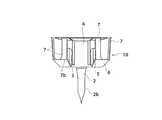
本発明の実施の形態を図面に基づいて説明する。図1は本発明のバイアルガイドの斜視図、図2はバイアルガイドの平面図、図3はバイアルガイドの正面図、図4はバイアルガイドの側面図、図5はバイアルガイドがニードルケースに仮係止状態で保持されている形態を示す要部の断面図であり、支持脚をガイドするガイドリブは省略されている。図6はバイアル瓶と輸液容器の連通状態を示す要部の部分断面図、図7はニードルケースの断面図、図8は輸液容器の全体を示す正面図である。
【0016】
図において、10はバイアルガイド、20は輸液容器、30はバイアル瓶である。バイアルガイド10は、輸液容器20の口部側に設けたニードルケース21(図7)内に仮係止状態で保持され(図5及び図8)、底板部1の中心に両頭針2を有していて、バイアル瓶30を装填すると該バイアル瓶30で押圧されて仮係止状態が解除されると共にニードルケース21内をスライド移動し、下部刺通針2aが前記輸液容器20の口部を封止した薄膜20aを刺通すると共に上部刺通針2bがバイアル瓶30の口栓(ゴム栓)32を刺通してバイアル瓶30と輸液容器20とが連通する(図6)ようになっている。
【0017】
前記バイアルガイド10には、前記両頭針2を中心とする位置に、バイアル口栓部31の外周部をガイドする弾性変形可能なガイド片3が分周的に立設されている。ガイド片3は高さの高い第1のガイド片4と高さの低い第2のガイド片5とからなり、第1のガイド片4と第2のガイド片5が交互に位置するようになっている。
【0018】
図の例では、前記第1のガイド片4及び第2のガイド片5はそれぞれ3方向に設けられ、前記第2のガイド片5の外側には底板1から斜め上方に延設した弾性変形可能な張り出し片6を介して支持脚7が分周的に立設されている。この支持脚7も弾性変形可能であり、前記ニードルケース21の内周面に摺接するようになっており、上端外側には前記ニードルケース21の開口縁22aに係合する仮係止用爪7aが設けられていると共に下部の前記張り出し片6の上縁が係止縁7bとなっていて、所定の位置まで挿入されると該係止縁7bがニードルケース21の内周面に突設した係止爪23に係合してロックされるようになっている。
【0019】
前記第2のガイド片5の上端部内側にはバイアル口栓部31の口金31aの後縁部に係合する係止爪5aが設けられており、第1のガイド片4の上端部には斜め外方向に延設された受け片4aが設けられている。この受け片4aはバイアル口栓部31を大まかに案内する。
【0020】
前記ニードルケース21は可撓性の輸液容器20と一体に形成され、ニードルケース21の内周面には、前記支持脚7をガイドしてバイアルガイド10全体が回転しないようにしたガイドリブ24が縦設されている。25は輸液取出し口であって、シールフィルム26でシールされている。27は懸吊用のフック、28はニードルケース21内にバイアルガイド10を仮係止状態で収納した後、開口部22を封止したシールである。
【0021】
以上のように、バイアルガイド10はニードルケース21内に仮係止状態で保持されており、ニードルケース21の開口部22はシール28で封止されている。使用に際しては、シール28を剥がしてバイアル瓶30を挿入すると、バイアル口栓部31は第1及び第2のガイド片4、5でガイドされてバイアル瓶30の口栓(ゴム栓)32の中心が上部刺通針2bの先端に位置決めされる。
そして、下部刺通針2aが前記輸液容器20の口部を封止した薄膜20aを刺通すると共に上部刺通針2bがバイアル瓶30の口栓(ゴム栓)32を刺通してバイアル瓶30と輸液容器20とが連通する。
【0022】
この際、前記のようにガイド片5の上端部内側に設けられた係止爪5aがバイアル口栓部31の口金31aの後縁部に係合してロックし、バイアル瓶30を保持する。
一方、2種以上の薬剤を混注する場合はバイアル瓶を交換する必要があるが、バイアル瓶30を上方向に引っ張った場合、バイアルガイド10は前記張り出し片6の上縁の係止縁7bがニードルケース21の内周面に突設した係止爪23に係合してロックされているため、バイアルガイド10がニードルケース21から外れることはないが、ガイド片5がバイアル瓶30を保持した状態で引っ張られるのに伴い、張り出し片6がガイド片5の上端部を広げる方向に弾性変形して、係止爪5aとバイアル口栓部31の口金31aの後縁部との係合が外れ、バイアル瓶30を容易に取り外すことができる。
【0023】
バイアルガイド、ニードルケースは、剛性の高い樹脂製であるのが好ましく、ポリエチレン、ポリプロピレン、ポリエステル、ポリアミド、ポリカーボネート、ABS樹脂、AS樹脂、ポリサルホン、ポリエーテルサルホン等が好適である。これらのうち、バイアルガイドに用いられる樹脂は、ABS樹脂、ポリエーテルサルホンが好ましく、ニードルケースはバイアルガイドが視認できる程度の透明性を有する樹脂が好ましく、具体的にはポリエチレン、ポリプロピレンが好ましい。
また、輸液容器は、通常、ポリエチレン(LDPE、L−LDPE、HDPE)、ポリプロピレン、エチレン−酢酸ビニル共重合体等のフィルム、シートがブロー成形されたものなどが使用される。
【0024】
【発明の効果】
本発明によれば、バイアル瓶をニードルケースに装填するとバイアル口栓部は両頭針を中心とする位置に分周的に設けられているガイド片によって確実にガイドされ、バイアル瓶のゴム栓の中心を上部刺通針の先端に確実に位置決めすることができる。また、ガイド片は弾性変形可能になっているから、サイズの異なるバイアル瓶であっても確実にガイドすることができる。
【0025】
ガイド片はバイアル口栓部をガイドするものであるからバイアル瓶の胴部近傍には何らの障害物になることはなく、上記のように使用後のバイアル瓶の取り外しも容易である等の効果を奏する。
【図面の簡単な説明】
【図1】本発明に係るバイアルガイドの斜視図である。
【図2】バイアルガイドの平面図である。
【図3】バイアルガイドの正面図である。
【図4】バイアルガイドの側面図である。
【図5】バイアルガイドがニードルケースに仮係止状態で保持されている形態を示す要部の断面図であり、支持脚をガイドするガイドリブは省略されている。
【図6】バイアル瓶と輸液容器の連通状態を示す要部の部分断面図である。
【図7】ニードルケースの断面図である。
【図8】輸液容器の全体を示す正面図である。
【符号の説明】
10 バイアルガイド
1 底板
2 両頭針
2a 上部刺通針
2b 下部刺通針
3 ガイド片
4 第1のガイド片
5 第2のガイド片
6 張り出し片
7 支持脚
20 輸液容器
21 ニードルケース
22 開口部
23 係止爪
30 バイアル瓶
31 バイアル口栓部
32 口栓[0001]
BACKGROUND OF THE INVENTION
The present invention relates to a vial guide for guiding a vial in a needle case of an infusion container when the vial and the infusion container are mixed and mixed with a double-ended needle, and the vial guide is held in a temporarily locked state. The present invention relates to a needle case and an infusion container in which the needle case is integrally formed.
[0002]
[Prior art]
Infusion containers widely used in the medical field include one or more drugs stored in vials, one or more physiological saline and glucose solutions, infusion preparations such as liquid nutrients, dialysis preparations, etc. It is used by mixing with a liquid formulation.
[0003]
In use, means for connecting and mixing a vial and a container containing a liquid preparation via a double-ended needle have been proposed in various forms. (For example, JP-A-8-308905, JP-A-9-140770, etc.)
[0004]
The mixing method using a double-ended needle is such that when mixing a vial into a guide capsule attached to a container of a liquid preparation, the container and the vial are communicated with a double-ended needle. There have been proposed infusion containers having a structure using a vial guide so that the double-ended needle pierces the center of the stopper of the vial bottle (for example, JP-A-5-317383 and JP-A-5-337163).
[0005]
[Problems to be solved by the invention]
There are several sizes of vials, and it is necessary for the vial guide to be compatible with various sizes of vials. When piercing a vial with a smaller diameter than the guide, it was necessary to puncture it with the center exactly aligned while looking at the needle. This is because the rubber stopper or aluminum cap that seals the vial will drop off if it is not pierced in the center, or the needle tip will break and a broken piece will enter the drug.
[0006]
Also, if the vial is short and lower than the height of the vial guide, when removing the vial after use, the fingers do not enter the gap between the vial and the vial guide, and the long needle is difficult to remove. , There is a drawback.
[0007]
An object of the present invention is to eliminate the drawbacks of the conventional infusion containers as described above, and can be easily and surely punctured without checking the position by looking at the tip of a double-ended needle, and after use. It is an object of the present invention to provide a vial guide in which a vial can be easily removed, a needle case in which the vial guide is held in a temporarily locked state, and an infusion container in which the needle case is integrally formed.
[0008]
[Means for Solving the Problems]
In the vial guide according to the present invention, the vial guide according to the present invention is held in a temporarily locked state in a needle case provided on the mouth side of the infusion container, and has a double-ended needle in the center of the bottom plate portion. When the vial is loaded, the vial is pressed to release the temporarily locked state and slides in the needle case, and the lower piercing needle pierces the thin film sealing the mouth portion of the infusion container. And a vial guide in which the upper piercing needle pierces the stopper of the vial so that the vial and the infusion container communicate with each other, and guides the outer periphery of the vial stopper at a position centering on the double-ended needle. The elastically deformable guide piece is erected in a frequency-dividing manner.
[0009]
According to a second aspect of the present invention, elastically deformable support legs that slidably contact the inner peripheral surface of the needle case are erected on the outer side of the guide piece, and the needle case is provided outside the upper end of the support leg. A temporary locking claw for engaging with the opening edge of the needle case is provided, and a locking edge is provided at the lower part. When inserted to a predetermined position, the locking edge protrudes from the inner peripheral surface of the needle case. It is characterized by being engaged and locked with the engaging claw.
[0010]
According to a third aspect of the present invention, the guide piece includes a first guide piece having a high height and a second guide piece having a low height, and the first guide pieces and the second guide pieces are alternately positioned. It is designed to do this.
[0011]
According to a fourth aspect of the present invention, a locking claw that engages with the rear edge of the mouthpiece of the vial stopper is provided inside the upper end of the second guide piece. The above-described one is characterized in that a receiving piece extending obliquely outward is provided at an upper end portion of the first guide piece.
[0012]
A needle case according to the present invention is characterized in that the vial guide according to any one of
[0013]
With the above configuration, the vial guide is held in the needle case in a temporarily locked state, and in use, when the vial cover is loaded by removing the seal covering the opening side of the needle case, It is reliably guided by a guide piece that is frequency-divided at a position around the needle, and the center of the rubber stopper of the vial can be reliably positioned at the tip of the upper piercing needle. Since the guide piece is elastically deformable, even a vial of different size can be reliably guided.
[0014]
Since the guide piece guides the vial stopper, there is no obstacle in the vicinity of the body of the vial and it can be disengaged by pulling the vial. It is easy to remove for replacement.
[0015]
DETAILED DESCRIPTION OF THE INVENTION
Embodiments of the present invention will be described with reference to the drawings. 1 is a perspective view of the vial guide of the present invention, FIG. 2 is a plan view of the vial guide, FIG. 3 is a front view of the vial guide, FIG. 4 is a side view of the vial guide, and FIG. It is sectional drawing of the principal part which shows the form hold | maintained in the stop state, and the guide rib which guides a support leg is abbreviate | omitted. FIG. 6 is a partial cross-sectional view of the main part showing the communication state between the vial and the infusion container, FIG. 7 is a cross-sectional view of the needle case, and FIG. 8 is a front view showing the entire infusion container.
[0016]
In the figure, 10 is a vial guide, 20 is an infusion container, and 30 is a vial. The
[0017]
In the
[0018]
In the example of the figure, the
[0019]
A locking
[0020]
The
[0021]
As described above, the
The
[0022]
At this time, as described above, the locking
On the other hand, when two or more kinds of drugs are mixed, it is necessary to replace the vial. However, when the
[0023]
The vial guide and the needle case are preferably made of a highly rigid resin, and polyethylene, polypropylene, polyester, polyamide, polycarbonate, ABS resin, AS resin, polysulfone, polyethersulfone, and the like are suitable. Among these, the resin used for the vial guide is preferably an ABS resin or polyether sulfone, and the needle case is preferably a resin having transparency that allows the vial guide to be visually recognized. Specifically, polyethylene and polypropylene are preferable.
In addition, as the infusion container, a film made of polyethylene (LDPE, L-LDPE, HDPE), polypropylene, ethylene-vinyl acetate copolymer, or a sheet formed by blow molding is usually used.
[0024]
【The invention's effect】
According to the present invention, when the vial bottle is loaded into the needle case, the vial mouth plug portion is reliably guided by the guide piece provided at the center of the double-ended needle, and the center of the rubber stopper of the vial bottle. Can be reliably positioned at the tip of the upper piercing needle. Further, since the guide piece can be elastically deformed, even vials having different sizes can be reliably guided.
[0025]
Since the guide piece guides the vial mouth plug, there is no obstacle near the vial body, and it is easy to remove the vial after use as described above. Play.
[Brief description of the drawings]
FIG. 1 is a perspective view of a vial guide according to the present invention.
FIG. 2 is a plan view of a vial guide.
FIG. 3 is a front view of a vial guide.
FIG. 4 is a side view of a vial guide.
FIG. 5 is a cross-sectional view of a main part showing a form in which a vial guide is held in a temporarily locked state by a needle case, and guide ribs for guiding support legs are omitted.
FIG. 6 is a partial cross-sectional view of a main part showing a communication state between a vial and an infusion container.
FIG. 7 is a cross-sectional view of a needle case.
FIG. 8 is a front view showing the entire infusion container.
[Explanation of symbols]
10
Claims (3)
Translated fromJapanese該ニードルケース内に、底板部の中心に両頭針を有していてバイアル瓶を装填すると該バイアル瓶で押圧されて仮係止状態が解除されると共にニードルケース内をスライド移動し、下部刺通針が前記輸液容器の口部を封止した薄膜を刺通すると共に上部刺通針がバイアル瓶の口栓を刺通してバイアル瓶と輸液容器とが連通するようにしたバイアルガイドが仮係止状態で保持され、
前記バイアルガイドは、前記両頭針を中心とする位置に、
分周的に立設されたバイアル口栓部の外周部をガイドする弾性変形可能なガイド片と、
該ガイド片の外側に分周的に立設されたニードルケースの内周面に摺接する弾性変形可能な支持脚とを有し、
前記ガイド片は、上部刺通針の高さより高く上端部には斜め外方向に延設された受け片が設けられている第1のガイド片と、
上部刺通針の高さより低く上端部内側にはバイアル口栓部の口金の後縁部に係合する係止爪が設けられている第2のガイド片とが交互に位置するようになっており、
前記支持脚の上端外側には前記ニードルケースの開口縁に係合する仮係止用爪が設けられていると共に下部には係止縁が設けられ、所定の位置まで挿入されると該係止縁がニードルケースの内周面に突設した係止爪に係合してロックされるバイアルガイドであることを特徴とするニードルケース。A needle case provided on the mouth side of the infusion container,
The needle case has a double-endedneedle in the center of thebottom plate portion. When a vial is loaded, the vial is pressed by the vial and the temporary locking state is released, and the needle case is slid and moved in the lower case. A vial guidethat pierces the thin film sealing the mouth of the infusion container and an upper piercing needle pierces the cap of the vial so that the vial and the infusion container communicate with each othertemporarily. Held in a state ,
The vial guide is positioned at the center of the double-ended needle,
An elastically deformable guide piece that guides the outer peripheral part of the vial stopper part erected in a divided manner,
An elastically deformable support leg that slidably contacts the inner peripheral surface of the needle case that is erected in a frequency-dividing manner on the outer side of the guide piece;
The guide piece is higher than the height of the upper piercing needle, and a first guide piece provided with a receiving piece extending obliquely outward at an upper end portion;
The second guide pieces provided with locking claws that engage with the rear edge of the mouthpiece of the vial cap portion are positioned alternately on the inner side of the upper end lower than the height of the upper piercing needle. And
A temporary locking claw that engages with the opening edge of the needle case is provided outside the upper end of the support leg, and a locking edge is provided at the lower portion. A needle case characterized in that the edge is a vial guide that is locked by being engaged with a locking claw protruding from the inner peripheral surface of theneedle case .
Priority Applications (1)
| Application Number | Priority Date | Filing Date | Title |
|---|---|---|---|
| JP2001299933AJP4817564B2 (en) | 2001-09-28 | 2001-09-28 | Needle case and infusion container |
Applications Claiming Priority (1)
| Application Number | Priority Date | Filing Date | Title |
|---|---|---|---|
| JP2001299933AJP4817564B2 (en) | 2001-09-28 | 2001-09-28 | Needle case and infusion container |
Publications (2)
| Publication Number | Publication Date |
|---|---|
| JP2003102807A JP2003102807A (en) | 2003-04-08 |
| JP4817564B2true JP4817564B2 (en) | 2011-11-16 |
Family
ID=19120596
Family Applications (1)
| Application Number | Title | Priority Date | Filing Date |
|---|---|---|---|
| JP2001299933AExpired - Fee RelatedJP4817564B2 (en) | 2001-09-28 | 2001-09-28 | Needle case and infusion container |
Country Status (1)
| Country | Link |
|---|---|
| JP (1) | JP4817564B2 (en) |
Families Citing this family (59)
| Publication number | Priority date | Publication date | Assignee | Title |
|---|---|---|---|---|
| US6997916B2 (en)* | 2004-01-02 | 2006-02-14 | Smiths Medical Asd, Inc. | Fluid transfer holder assembly and a method of fluid transfer |
| IL161660A0 (en) | 2004-04-29 | 2004-09-27 | Medimop Medical Projects Ltd | Liquid drug delivery device |
| US8070739B2 (en) | 2005-08-11 | 2011-12-06 | Medimop Medical Projects Ltd. | Liquid drug transfer devices for failsafe correct snap fitting onto medicinal vials |
| IL182605A0 (en) | 2007-04-17 | 2007-07-24 | Medimop Medical Projects Ltd | Fluid control device with manually depressed actuator |
| EP2190518B1 (en) | 2007-09-18 | 2016-01-27 | Medimop Medical Projects Ltd. | Medicament mixing and injection apparatus |
| IL201323A0 (en) | 2009-10-01 | 2010-05-31 | Medimop Medical Projects Ltd | Fluid transfer device for assembling a vial with pre-attached female connector |
| IL202070A0 (en) | 2009-11-12 | 2010-06-16 | Medimop Medical Projects Ltd | Inline liquid drug medical device |
| IL202069A0 (en) | 2009-11-12 | 2010-06-16 | Medimop Medical Projects Ltd | Fluid transfer device with sealing arrangement |
| EP2353629A1 (en)* | 2010-02-08 | 2011-08-10 | Fresenius Kabi Deutschland GmbH | Connector for containers containing medical agents |
| DK2512399T3 (en) | 2010-02-24 | 2015-06-22 | Medimop Medical Projects Ltd | Fluid transfer device with vent arrangement |
| DK2512398T3 (en) | 2010-02-24 | 2014-10-13 | Medimop Medical Projects Ltd | Liquid drug transfer device with vented ampoule adapter |
| USD669980S1 (en) | 2010-10-15 | 2012-10-30 | Medimop Medical Projects Ltd. | Vented vial adapter |
| IL209290A0 (en) | 2010-11-14 | 2011-01-31 | Medimop Medical Projects Ltd | Inline liquid drug medical device having rotary flow control member |
| IL212420A0 (en) | 2011-04-17 | 2011-06-30 | Medimop Medical Projects Ltd | Liquid drug transfer assembly |
| IL215699A0 (en) | 2011-10-11 | 2011-12-29 | Medimop Medical Projects Ltd | Liquid drug reconstitution assemblage for use with iv bag and drug vial |
| USD674088S1 (en) | 2012-02-13 | 2013-01-08 | Medimop Medical Projects Ltd. | Vial adapter |
| USD737436S1 (en) | 2012-02-13 | 2015-08-25 | Medimop Medical Projects Ltd. | Liquid drug reconstitution assembly |
| USD720451S1 (en) | 2012-02-13 | 2014-12-30 | Medimop Medical Projects Ltd. | Liquid drug transfer assembly |
| IL219065A0 (en) | 2012-04-05 | 2012-07-31 | Medimop Medical Projects Ltd | Fluid transfer device with manual operated cartridge release arrangement |
| IL221635A0 (en) | 2012-08-26 | 2012-12-31 | Medimop Medical Projects Ltd | Drug vial mixing and transfer device for use with iv bag and drug vial |
| IL221634A0 (en) | 2012-08-26 | 2012-12-31 | Medimop Medical Projects Ltd | Universal drug vial adapter |
| DK2872100T3 (en) | 2012-09-13 | 2017-07-10 | Medimop Medical Projects Ltd | Telescopic female adapter for drug ampoule |
| USD734868S1 (en) | 2012-11-27 | 2015-07-21 | Medimop Medical Projects Ltd. | Drug vial adapter with downwardly depending stopper |
| IL225734A0 (en) | 2013-04-14 | 2013-09-30 | Medimop Medical Projects Ltd | Ready-to-use drug vial assemblages including drug vial and drug vial closure having fluid transfer member, and drug vial closure therefor |
| CN105228676B (en) | 2013-05-10 | 2018-01-05 | 麦迪麦珀医疗工程有限公司 | Include the medical treatment device of the vial adapter with inline dry kit |
| USD765837S1 (en) | 2013-08-07 | 2016-09-06 | Medimop Medical Projects Ltd. | Liquid transfer device with integral vial adapter |
| USD767124S1 (en) | 2013-08-07 | 2016-09-20 | Medimop Medical Projects Ltd. | Liquid transfer device with integral vial adapter |
| DE212014000169U1 (en) | 2013-08-07 | 2016-03-14 | Medimop Medical Projects Ltd. | Fluid transfer devices for use with infusion fluid containers |
| USD794183S1 (en) | 2014-03-19 | 2017-08-08 | Medimop Medical Projects Ltd. | Dual ended liquid transfer spike |
| KR200480468Y1 (en)* | 2014-03-26 | 2016-05-27 | 안영각 | Packing case |
| USD757933S1 (en) | 2014-09-11 | 2016-05-31 | Medimop Medical Projects Ltd. | Dual vial adapter assemblage |
| JP6358724B2 (en) | 2015-01-05 | 2018-07-18 | ウエスト・ファーマ.サービシーズ・イスラエル,リミテッド | Dual vial adapter assembly with easy removable pill adapter to ensure accurate use |
| WO2017009822A1 (en) | 2015-07-16 | 2017-01-19 | Medimop Medical Projects Ltd | Liquid drug transfer devices for secure telescopic snap fit on injection vials |
| USD801522S1 (en) | 2015-11-09 | 2017-10-31 | Medimop Medical Projects Ltd. | Fluid transfer assembly |
| CN115721558A (en) | 2015-11-25 | 2023-03-03 | 西部制药服务以色列有限公司 | Dual vial adapter assembly comprising a drug vial adapter having a self-sealing inlet valve |
| IL245803A0 (en) | 2016-05-24 | 2016-08-31 | West Pharma Services Il Ltd | Dual vial adapter assemblages including vented drug vial adapter and vented liquid vial adapter |
| IL245800A0 (en) | 2016-05-24 | 2016-08-31 | West Pharma Services Il Ltd | Dual vial adapter assemblages including identical twin vial adapters |
| IL246073A0 (en) | 2016-06-06 | 2016-08-31 | West Pharma Services Il Ltd | Fluid transfer devices for use with drug pump cartridge having slidable driving plunger |
| IL247376A0 (en) | 2016-08-21 | 2016-12-29 | Medimop Medical Projects Ltd | Syringe assembly |
| USD832430S1 (en) | 2016-11-15 | 2018-10-30 | West Pharma. Services IL, Ltd. | Dual vial adapter assemblage |
| IL249408A0 (en) | 2016-12-06 | 2017-03-30 | Medimop Medical Projects Ltd | Liquid transfer device for use with infusion liquid container and pincers-like hand tool for use therewith for releasing intact drug vial therefrom |
| IL251458A0 (en) | 2017-03-29 | 2017-06-29 | Medimop Medical Projects Ltd | User actuated liquid drug transfer devices for use in ready-to-use (rtu) liquid drug transfer assemblages |
| JP6972747B2 (en)* | 2017-08-03 | 2021-11-24 | 株式会社ジェイ・エム・エス | Adapter assembly |
| IL254802A0 (en) | 2017-09-29 | 2017-12-31 | Medimop Medical Projects Ltd | Dual vial adapter assemblages with twin vented female vial adapters |
| JP7235286B2 (en)* | 2018-02-27 | 2023-03-08 | 内外化成株式会社 | Transfusion material and drug mixing kit |
| JP7171037B2 (en)* | 2018-04-19 | 2022-11-15 | 内外化成株式会社 | Transfusion member and manufacturing method thereof |
| USD903864S1 (en) | 2018-06-20 | 2020-12-01 | West Pharma. Services IL, Ltd. | Medication mixing apparatus |
| JP1630477S (en) | 2018-07-06 | 2019-05-07 | ||
| CN109044826A (en)* | 2018-07-25 | 2018-12-21 | 重庆莱美药业股份有限公司 | A kind of mixed medicine glass with clamp structure |
| USD923812S1 (en) | 2019-01-16 | 2021-06-29 | West Pharma. Services IL, Ltd. | Medication mixing apparatus |
| JP1648075S (en) | 2019-01-17 | 2019-12-16 | ||
| JP7209849B2 (en) | 2019-01-18 | 2023-01-20 | ウェスト・ファーマ・サービシーズ・アイエル・リミテッド | Liquid transfer device for use with IV bottles |
| US11918542B2 (en) | 2019-01-31 | 2024-03-05 | West Pharma. Services IL, Ltd. | Liquid transfer device |
| JP7284289B2 (en) | 2019-04-09 | 2023-05-30 | ウェスト ファーマ サービシーズ イスラエル リミテッド | Infusion device with integrated syringe |
| KR20240122586A (en) | 2019-04-30 | 2024-08-12 | 웨스트 파마. 서비시즈 일, 리미티드 | Liquid transfer device with dual lumen iv spike |
| CN110279584A (en)* | 2019-08-09 | 2019-09-27 | 江苏丞宇米特医疗科技有限公司 | Formula needle for inserting bottle is plugged and fixed |
| CN113148424A (en)* | 2020-01-22 | 2021-07-23 | 河北天成药业股份有限公司 | A double-ended needle large-capacity injection container that can be quickly dispensed |
| USD956958S1 (en) | 2020-07-13 | 2022-07-05 | West Pharma. Services IL, Ltd. | Liquid transfer device |
| FR3117774B1 (en)* | 2020-12-23 | 2023-03-31 | A Raymond Et Cie | ADAPTIVE CAP PIERCING CLIP FOR MEDICAL VIAL |
Family Cites Families (4)
| Publication number | Priority date | Publication date | Assignee | Title |
|---|---|---|---|---|
| JPH05317383A (en)* | 1992-05-19 | 1993-12-03 | Nissho Corp | Solution container equipped with means for communicating with chemical container |
| JPH08238300A (en)* | 1995-03-07 | 1996-09-17 | Nissho Corp | Infusion container |
| US5893397A (en)* | 1996-01-12 | 1999-04-13 | Bioject Inc. | Medication vial/syringe liquid-transfer apparatus |
| JP3947984B2 (en)* | 1997-04-09 | 2007-07-25 | 株式会社大塚製薬工場 | Plastic double-ended needle |
- 2001
- 2001-09-28JPJP2001299933Apatent/JP4817564B2/ennot_activeExpired - Fee Related
Also Published As
| Publication number | Publication date |
|---|---|
| JP2003102807A (en) | 2003-04-08 |
Similar Documents
| Publication | Publication Date | Title |
|---|---|---|
| JP4817564B2 (en) | Needle case and infusion container | |
| JP2605345Y2 (en) | Drug container | |
| US5826713A (en) | Fluid vessel | |
| US8512308B2 (en) | Connector, syringe assembly, and connector for mixing | |
| ES2608284T3 (en) | Reconstitution device | |
| JP5656846B2 (en) | Mixing device and double needle insertion method | |
| US7404814B2 (en) | Infusion vessel | |
| JP2004194953A (en) | Liquid transfusion implement | |
| JP2005521487A (en) | Sliding reconstitution for diluent containers | |
| JPH06239352A (en) | Solution injection set | |
| KR101699090B1 (en) | Spout and liquid containing body with spout | |
| US20140021076A1 (en) | Double-ended needle and mixing instrument | |
| JP3514505B2 (en) | Manufacturing method of solution container | |
| JP3415714B2 (en) | Chemical transfer device and chemical transfer system | |
| JPH08238300A (en) | Infusion container | |
| JP3478320B2 (en) | Drug container with communication means | |
| JPH0422745Y2 (en) | ||
| JP3345860B2 (en) | Infusion container | |
| JP4058750B2 (en) | Solution injection device | |
| JP2006225021A (en) | Liquid container dispensing device | |
| JPH05317384A (en) | Container of liquid for transfusion | |
| JP3175127B2 (en) | Infusion container | |
| EP2874594B1 (en) | Reconstitution device with tip cap | |
| JP3702377B2 (en) | Solution container with double-ended needle | |
| JP2000070341A (en) | Infusion container with double-ended needle |
Legal Events
| Date | Code | Title | Description |
|---|---|---|---|
| A711 | Notification of change in applicant | Free format text:JAPANESE INTERMEDIATE CODE: A711 Effective date:20070531 | |
| A521 | Request for written amendment filed | Free format text:JAPANESE INTERMEDIATE CODE: A821 Effective date:20070601 | |
| A621 | Written request for application examination | Free format text:JAPANESE INTERMEDIATE CODE: A621 Effective date:20080826 | |
| A977 | Report on retrieval | Free format text:JAPANESE INTERMEDIATE CODE: A971007 Effective date:20101129 | |
| A131 | Notification of reasons for refusal | Free format text:JAPANESE INTERMEDIATE CODE: A131 Effective date:20101207 | |
| A521 | Request for written amendment filed | Free format text:JAPANESE INTERMEDIATE CODE: A523 Effective date:20110202 | |
| TRDD | Decision of grant or rejection written | ||
| A01 | Written decision to grant a patent or to grant a registration (utility model) | Free format text:JAPANESE INTERMEDIATE CODE: A01 Effective date:20110816 | |
| A01 | Written decision to grant a patent or to grant a registration (utility model) | Free format text:JAPANESE INTERMEDIATE CODE: A01 | |
| A61 | First payment of annual fees (during grant procedure) | Free format text:JAPANESE INTERMEDIATE CODE: A61 Effective date:20110830 | |
| FPAY | Renewal fee payment (event date is renewal date of database) | Free format text:PAYMENT UNTIL: 20140909 Year of fee payment:3 | |
| R150 | Certificate of patent or registration of utility model | Ref document number:4817564 Country of ref document:JP Free format text:JAPANESE INTERMEDIATE CODE: R150 Free format text:JAPANESE INTERMEDIATE CODE: R150 | |
| R250 | Receipt of annual fees | Free format text:JAPANESE INTERMEDIATE CODE: R250 | |
| R250 | Receipt of annual fees | Free format text:JAPANESE INTERMEDIATE CODE: R250 | |
| R250 | Receipt of annual fees | Free format text:JAPANESE INTERMEDIATE CODE: R250 | |
| R250 | Receipt of annual fees | Free format text:JAPANESE INTERMEDIATE CODE: R250 | |
| R250 | Receipt of annual fees | Free format text:JAPANESE INTERMEDIATE CODE: R250 | |
| R250 | Receipt of annual fees | Free format text:JAPANESE INTERMEDIATE CODE: R250 | |
| R250 | Receipt of annual fees | Free format text:JAPANESE INTERMEDIATE CODE: R250 | |
| LAPS | Cancellation because of no payment of annual fees |