JP4816145B2 - Cable-type steering device - Google Patents
Cable-type steering deviceDownload PDFInfo
- Publication number
- JP4816145B2 JP4816145B2JP2006057269AJP2006057269AJP4816145B2JP 4816145 B2JP4816145 B2JP 4816145B2JP 2006057269 AJP2006057269 AJP 2006057269AJP 2006057269 AJP2006057269 AJP 2006057269AJP 4816145 B2JP4816145 B2JP 4816145B2
- Authority
- JP
- Japan
- Prior art keywords
- cable
- pulley
- support case
- case portion
- steering
- Prior art date
- Legal status (The legal status is an assumption and is not a legal conclusion. Google has not performed a legal analysis and makes no representation as to the accuracy of the status listed.)
- Expired - Fee Related
Links
Images


Classifications
- B—PERFORMING OPERATIONS; TRANSPORTING
- B62—LAND VEHICLES FOR TRAVELLING OTHERWISE THAN ON RAILS
- B62D—MOTOR VEHICLES; TRAILERS
- B62D1/00—Steering controls, i.e. means for initiating a change of direction of the vehicle
- B62D1/02—Steering controls, i.e. means for initiating a change of direction of the vehicle vehicle-mounted
- B62D1/16—Steering columns
- B62D1/163—Part of the steering column replaced by flexible means, e.g. cable or belt
- F—MECHANICAL ENGINEERING; LIGHTING; HEATING; WEAPONS; BLASTING
- F16—ENGINEERING ELEMENTS AND UNITS; GENERAL MEASURES FOR PRODUCING AND MAINTAINING EFFECTIVE FUNCTIONING OF MACHINES OR INSTALLATIONS; THERMAL INSULATION IN GENERAL
- F16C—SHAFTS; FLEXIBLE SHAFTS; ELEMENTS OR CRANKSHAFT MECHANISMS; ROTARY BODIES OTHER THAN GEARING ELEMENTS; BEARINGS
- F16C1/00—Flexible shafts; Mechanical means for transmitting movement in a flexible sheathing
- F16C1/10—Means for transmitting linear movement in a flexible sheathing, e.g. "Bowden-mechanisms"
- F16C1/12—Arrangements for transmitting movement to or from the flexible member
- F16C1/18—Arrangements for transmitting movement to or from the flexible member in which the end portion of the flexible member is laid along a curved surface of a pivoted member
- F—MECHANICAL ENGINEERING; LIGHTING; HEATING; WEAPONS; BLASTING
- F16—ENGINEERING ELEMENTS AND UNITS; GENERAL MEASURES FOR PRODUCING AND MAINTAINING EFFECTIVE FUNCTIONING OF MACHINES OR INSTALLATIONS; THERMAL INSULATION IN GENERAL
- F16C—SHAFTS; FLEXIBLE SHAFTS; ELEMENTS OR CRANKSHAFT MECHANISMS; ROTARY BODIES OTHER THAN GEARING ELEMENTS; BEARINGS
- F16C1/00—Flexible shafts; Mechanical means for transmitting movement in a flexible sheathing
- F16C1/26—Construction of guiding-sheathings or guiding-tubes
- F16C1/262—End fittings; Attachment thereof to the sheathing or tube
- F—MECHANICAL ENGINEERING; LIGHTING; HEATING; WEAPONS; BLASTING
- F16—ENGINEERING ELEMENTS AND UNITS; GENERAL MEASURES FOR PRODUCING AND MAINTAINING EFFECTIVE FUNCTIONING OF MACHINES OR INSTALLATIONS; THERMAL INSULATION IN GENERAL
- F16C—SHAFTS; FLEXIBLE SHAFTS; ELEMENTS OR CRANKSHAFT MECHANISMS; ROTARY BODIES OTHER THAN GEARING ELEMENTS; BEARINGS
- F16C1/00—Flexible shafts; Mechanical means for transmitting movement in a flexible sheathing
- F16C1/10—Means for transmitting linear movement in a flexible sheathing, e.g. "Bowden-mechanisms"
- F16C1/106—Plurality of transmitting means, e.g. two or more parallel "Bowden cables"
- F—MECHANICAL ENGINEERING; LIGHTING; HEATING; WEAPONS; BLASTING
- F16—ENGINEERING ELEMENTS AND UNITS; GENERAL MEASURES FOR PRODUCING AND MAINTAINING EFFECTIVE FUNCTIONING OF MACHINES OR INSTALLATIONS; THERMAL INSULATION IN GENERAL
- F16C—SHAFTS; FLEXIBLE SHAFTS; ELEMENTS OR CRANKSHAFT MECHANISMS; ROTARY BODIES OTHER THAN GEARING ELEMENTS; BEARINGS
- F16C2326/00—Articles relating to transporting
- F16C2326/20—Land vehicles
- F16C2326/24—Steering systems, e.g. steering rods or columns
- Y—GENERAL TAGGING OF NEW TECHNOLOGICAL DEVELOPMENTS; GENERAL TAGGING OF CROSS-SECTIONAL TECHNOLOGIES SPANNING OVER SEVERAL SECTIONS OF THE IPC; TECHNICAL SUBJECTS COVERED BY FORMER USPC CROSS-REFERENCE ART COLLECTIONS [XRACs] AND DIGESTS
- Y10—TECHNICAL SUBJECTS COVERED BY FORMER USPC
- Y10T—TECHNICAL SUBJECTS COVERED BY FORMER US CLASSIFICATION
- Y10T74/00—Machine element or mechanism
- Y10T74/20—Control lever and linkage systems
- Y10T74/20396—Hand operated
- Y10T74/20402—Flexible transmitter [e.g., Bowden cable]
Landscapes
- Engineering & Computer Science (AREA)
- General Engineering & Computer Science (AREA)
- Mechanical Engineering (AREA)
- Health & Medical Sciences (AREA)
- Oral & Maxillofacial Surgery (AREA)
- Chemical & Material Sciences (AREA)
- Combustion & Propulsion (AREA)
- Transportation (AREA)
- Power Steering Mechanism (AREA)
- Pulleys (AREA)
- Flexible Shafts (AREA)
- Steering Controls (AREA)
Abstract
Description
Translated fromJapanese本発明は、操舵ハンドルとステアリングギヤ機構とをボーデンケーブル等の操作ケーブルで接続したケーブル式ステアリング装置の技術分野に属する。 The present invention belongs to the technical field of a cable-type steering device in which a steering handle and a steering gear mechanism are connected by an operation cable such as a Bowden cable.
従来、操舵ハンドルとステアリングギヤ機構とを操作ケーブルで接続したケーブル式ステアリング装置におけるセット張力調整機構は、プーリケーシングに対するアウターチューブの2箇所の接続部を、各々のアジャストナットで移動させることで、インナーケーブルのセット張力を調整可能にしており、操舵ハンドルを有する操作部側に設けられたトルクセンサからのセンサ値を測定して、各々のアジャストナットを調整している(例えば、特許文献1参照。)。
しかしながら、上記従来例におけるセット張力調整機構にあっては、ステアリングギヤ機構および操舵ハンドルが共にニュートラル状態で、操作ケーブルユニットを組み付け、プーリケーシングに対する2箇所のアウターチューブ接続部を、各々のアジャストナットの回転量・送り込み量を管理しながら調整作業が行われる。このように、2箇所のアウターチューブ接続部のそれぞれに対するセット張力の調整作業となるため、作業が面倒であるし、工数を要してしまうし、さらに、2箇所のセット張力を均等に調整するのが困難である。そして、面倒な調整作業を行っても均等に操舵ハンドルの左右ガタ(=ステアリング左右ガタ)を設定することができない場合、ハンドル操作方向が右方向か左方向かで操舵力と操舵角にバラツキが発生する、という問題があった。 However, in the set tension adjusting mechanism in the above-described conventional example, the steering cable mechanism and the steering handle are both in the neutral state, the operation cable unit is assembled, and the two outer tube connecting portions with respect to the pulley casing are connected to the respective adjustment nuts. Adjustment work is performed while controlling the amount of rotation and the amount of feed. As described above, since the set tension is adjusted for each of the two outer tube connection portions, the work is troublesome, requires man-hours, and the set tensions at the two locations are adjusted equally. Is difficult. If the left and right backlash (= steering left and right backlash) of the steering wheel cannot be set evenly even after troublesome adjustment work, the steering force and the steering angle vary depending on whether the steering wheel operation direction is right or left. There was a problem that it occurred.
本発明は、上記問題に着目してなされたもので、その目的とするところは、2分割したプーリケースを相対移動させるだけの短時間で、且つ、容易なインナーケーブルのセット張力調整作業により、ステアリング左右ガタを均等に設定することができるケーブル式ステアリング装置を提供することにある。 The present invention has been made paying attention to the above-mentioned problem, and its purpose is to adjust the set tension of the inner cable in a short period of time by which the pulley case divided into two parts is relatively moved. An object of the present invention is to provide a cable-type steering device that can set the steering left and right backlash equally.
上述の目的を達成するため、本発明では、
運転者が操作する操作部に設けられたステアリング側ケーブルプーリと、
操向輪を転舵する転舵部に設けられた操向輪側ケーブルプーリと、
前記両ケーブルプーリに対し互いに逆方向に巻き付けられた状態で連結する2本のインナーケーブルと、
前記ステアリング側ケーブルプーリを収納する第1プーリケースと、
前記操向輪側ケーブルプーリを収納する第2プーリケースと、
前記2本のインナーケーブルを覆うと共に、両プーリケースを連結する2本のアウターチューブと、
を備えたケーブル式ステアリング装置において、
前記第1プーリケースと第2プーリケースのうち少なくとも一方のプーリケースは、
前記プーリを回転自在に支持するプーリ支持ケース部と、
前記2本のアウターチューブの2つの端部を支持すると共に、前記プーリ支持ケース部に対してインナーケーブルの巻き取り・送り出し方向に対し相対移動可能に支持されるケーブル支持ケース部と、を有し、
前記プーリ支持ケース部と前記ケーブル支持ケース部との間には、インナーケーブルの巻き取り・送り出し方向に対し互いの相対位置関係を手動で調整可能なケーブル張力調整手段を有することを特徴とする。In order to achieve the above object, the present invention provides:
A steering-side cable pulley provided in an operation unit operated by the driver;
A steered wheel side cable pulley provided in a steered portion that steers steered wheels;
Two inner cables connected to the two cable pulleys while being wound in opposite directions;
A first pulley case for accommodating the steering side cable pulley;
A second pulley case for housing the steering wheel side cable pulley;
Two outer tubes that cover the two inner cables and connect the two pulley cases;
In the cable-type steering device provided with
At least one of the first pulley case and the second pulley case is
A pulley support case for rotatably supporting the pulley;
To support the two ends of the two outer tubes,have a, and cable supporting part thatwill be relatively movably supported to the winding-dispensing direction of the inner cable to the pulley supporting part,
Between the pulley support case portion and the cable support case portion, there is provided a cable tension adjusting means capable of manually adjusting a relative positional relationship with respect to a winding / feeding direction of the inner cable .
本発明のケーブル式ステアリング装置において、2本のインナーケーブルのセット張力を調整する際は、操作部と転舵部とをニュートラル状態とし、プーリケースを構成するプーリ支持ケース部とケーブル支持ケース部とをインナーケーブルの巻き取り・送り出し方向に対し相対移動させる。
このとき、プーリ支持ケース部はプーリを回転自在に支持しているし、ケーブル支持ケース部は2本のアウターチューブの2つの端部を支持しているため、プーリ支持ケース部とケーブル支持ケース部との相対移動により、プーリ支持位置と2本のアウターチューブの支持位置との間隔が変動する。言い換えると、2本のインナーケーブルのセット張力の調整は、プーリ支持位置に対し2本のアウターチューブ支持位置を均等に移動させることで行われる。
すなわち、従来のセット張力調整作業は、プーリケーシングに対する2箇所のアウターチューブ接続部を、各々のアジャストナットの回転量・送り込み量を管理しながら行うため、作業が面倒であるし、時間を要してしまう。
これに対し、本発明のセット張力調整作業では、プーリ支持ケース部とケーブル支持ケース部とを相対移動させるだけの作業により、短時間で、且つ、容易にインナーケーブルのセット張力調整作業を行うことができる。
さらに、従来のセット張力調整作業は、2箇所のアウターチューブ接続部のそれぞれに対するセット張力の調整作業となるため、独立した2箇所のセット張力を均等に調整するのが困難である。
これに対し、本発明のセット張力調整作業では、プーリ支持ケース部とケーブル支持ケース部とを相対移動させると、プーリ支持位置に対し2本のアウターチューブ支持位置を均等に移動させることになるため、左右操舵時の操舵力と操舵角のバラツキ原因となるステアリング左右ガタを均等に設定することができる。
この結果、2分割したプーリケースを相対移動させるだけの短時間で、且つ、容易なインナーケーブルのセット張力調整作業により、ステアリング左右ガタを均等に設定することができる。In the cable-type steering device of the present invention, when adjusting the set tension of the two inner cables, the operation unit and the steered unit are set to the neutral state, and the pulley support case unit and the cable support case unit constituting the pulley case are provided. Is moved relative to the winding and feeding direction of the inner cable.
At this time, the pulley support case portion rotatably supports the pulley, and the cable support case portion supports two ends of the two outer tubes, so that the pulley support case portion and the cable support case portion The distance between the pulley support position and the support positions of the two outer tubes fluctuates due to relative movement. In other words, the set tension of the two inner cables is adjusted by moving the two outer tube support positions evenly with respect to the pulley support position.
In other words, the conventional set tension adjustment work is performed in a troublesome and time-consuming manner because the two outer tube connecting portions with respect to the pulley casing are performed while controlling the rotation amount and feed amount of each adjustment nut. End up.
On the other hand, in the set tension adjustment work of the present invention, the inner cable set tension adjustment work can be easily performed in a short time by simply moving the pulley support case part and the cable support case part relative to each other. Can do.
Furthermore, since the conventional set tension adjustment work is an adjustment work of the set tension for each of the two outer tube connecting portions, it is difficult to uniformly adjust the set tensions of two independent places.
On the other hand, in the set tension adjustment work of the present invention, when the pulley support case portion and the cable support case portion are moved relative to each other, the two outer tube support positions are moved evenly with respect to the pulley support position. Further, it is possible to set the steering left and right backlash, which cause variations in the steering force and the steering angle during left and right steering, evenly.
As a result, it is possible to set the steering left and right backlash equally in a short period of time by which the pulley case divided into two parts is relatively moved and by an easy inner cable set tension adjustment operation.
以下、本発明のケーブル式ステアリング装置を実施するための最良の形態を、図面に示す実施例1〜実施例4に基づいて説明する。 Hereinafter, the best mode for carrying out the cable type steering apparatus of the present invention will be described based on Examples 1 to 4 shown in the drawings.
まず、構成を説明する。
[全体構成]
図1は、実施例1のケーブル式ステアリング装置をバックアップケーブルとして適用したステアバイワイヤ(SBW)システムの構成図である。
実施例1のSBWシステムは、ハンドル(操作部)1と、操舵反力モータ2と、操舵角センサ3と、バックアップクラッチ4と、バックアップケーブル5と、転舵モータ6と、転舵角センサ7と、舵取り機構8(転舵部)と、右前輪9a(操向輪)と、左前輪9b(操向輪)と、操舵反力コントローラ10と、転舵コントローラ11と、車速センサ12と、を備えている。First, the configuration will be described.
[overall structure]
FIG. 1 is a configuration diagram of a steer-by-wire (SBW) system in which the cable-type steering device according to the first embodiment is applied as a backup cable.
The SBW system according to the first embodiment includes a handle (operation unit) 1, a steering reaction force motor 2, a steering angle sensor 3, a backup clutch 4, a backup cable 5, a
実施例1のSBWシステムは機構構成として、運転者が操作するハンドル1と、前記ハンドル1とは機械的に切り離され、左右前輪9a,9bを転舵する舵取り機構8と、前記ハンドル1に操舵反力を付与する操舵反力モータ2と、前記舵取り機構8に転舵力を付与する転舵モータ6と、前記ハンドル1と前記舵取り機構8とを機械的に断接するバックアップ機構として、バックアップクラッチ4およびバックアップケーブル5と、を備えている。 The SBW system according to the first embodiment is structured such that a steering wheel 1 operated by a driver, a
実施例1のSBWシステムは制御構成として、前記バックアップクラッチ4の開放により前記ハンドル1と前記舵取り機構8を切り離し、前記ハンドル1の操作状態に応じた転舵角となるように前記転舵モータ6を駆動する制御指令を出力する転舵装置用コントローラ11と、前記舵取り機構8の転舵状態に応じた操舵反力を付与するように前記操舵反力モータ2を駆動する制御指令を出力する操舵反力装置用コントローラ10と、を備えている。 The SBW system according to the first embodiment has a control configuration in which the
また、SBWシステムの一部に異常が認められた場合には、速やかにバックアップクラッチ4を接続し、バックアップケーブル5を介してハンドル1と舵取り機構8とを機械的に連結してSBW制御を中止する。このシステム異常のうち、操舵反力モータ2と転舵モータ6の少なくとも一方を駆動可能である場合には、SBW制御から、運転者の操作力にアシスト力を付加するように操舵反力モータ2と転舵モータ6の少なくとも一方を駆動するアシスト制御に変更する。 In addition, when an abnormality is found in a part of the SBW system, the backup clutch 4 is quickly connected, and the steering wheel 1 and the
[バックアップケーブルの構成]
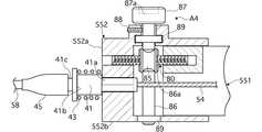
図2は実施例1のバックアップケーブル5のステアリング側のケーブルプーリ部を示す上方斜視図、図3は実施例1のバックアップケーブル5のステアリング側のケーブルプーリ部を示す下方分解斜視図である。[Configuration of backup cable]
2 is an upper perspective view showing a cable pulley portion on the steering side of the backup cable 5 according to the first embodiment, and FIG. 3 is a lower exploded perspective view showing a cable pulley portion on the steering side of the backup cable 5 according to the first embodiment.
実施例1のバックアップケーブル5は、図1に示すように、運転者が操作する操作部に設けられたステアリング側ケーブルプーリ51と、左右前輪9a,9bを転舵する転舵部に設けられた操向輪側ケーブルプーリ52と、を備えている。 As shown in FIG. 1, the backup cable 5 of the first embodiment is provided in a steering
前記ステアリング側ケーブルプーリ51と前記操向輪側ケーブルプーリ52とは、図3に示すように、2本のインナーケーブル53,54により前記両ケーブルプーリ51,52に対し互いに逆方向に巻き付けられた状態で連結されている。 As shown in FIG. 3, the steering
実施例1のバックアップケーブル5は、図1に示すように、前記ステアリング側ケーブルプーリ51を収納する第1プーリケース55と、前記操向輪側ケーブルプーリ52を収納する第2プーリケース56と、を備えている。 As shown in FIG. 1, the backup cable 5 according to the first embodiment includes a
前記第1プーリケース55と前記第2プーリケース56とは、図2及び図3に示すように、2本のアウターチューブ57,58により連結され、かつ、前記2本のインナーケーブル53,54を覆っている。 As shown in FIGS. 2 and 3, the
前記第1プーリケース55は、図2及び図3に示すように、前記ステアリング側ケーブルプーリ51を回転自在に支持するプーリ支持ケース部551と、前記2本のアウターチューブ57,58の2つの端部を支持すると共に、前記プーリ支持ケース部551に対してインナーケーブル53,54の巻き取り・送り出し方向に対し相対移動可能に支持するケーブル支持ケース部552と、を有する。 As shown in FIGS. 2 and 3, the
前記プーリ支持ケース部551と前記ケーブル支持ケース部552との間には、図2及び図3に示すように、インナーケーブル53,54の巻き取り・送り出し方向に対し互いの相対位置関係を調整する第1ケーブル張力調整手段A1を有する(図4及び図5参照)。 Between the pulley
前記プーリ支持ケース部551は、図2及び図3に示すように、プーリ支持ケースアッパー551aとプーリ支持ケースロア551bとの上下分割構造により構成され、プーリ支持ケースアッパー551aとプーリ支持ケースロア551bは、ボルト60,61,62により締結されている。
そして、前記プーリ支持ケース部551には、図2及び図3に示すように、ステアリング側ケーブルプーリ51の上面を覆う上面カバー63と、ステアリング側ケーブルプーリ51の下面の一部を覆うと共に、操作部側に固定する下面ブラケット64と、が固定されている。As shown in FIGS. 2 and 3, the pulley
2 and 3, the pulley
前記ケーブル支持ケース部552は、図2及び図3に示すように、ケーブル支持ケースアッパー552aとケーブル支持ケースロア552bとの上下分割構造により構成され、ケーブル支持ケースアッパー552aとケーブル支持ケースロア552bは、ボルト65,66,67により締結されている。
そして、前記ケーブル支持ケース部552は、前記プーリ支持ケース部551の端部位置を覆う形状に設定され、図3に示すように、プーリ支持ケース部551の端部位置がケーブル支持ケースアッパー552aに組み込まれ、その上からケーブル支持ケースロア552bを挟み込み、ボルト65,66,67により締結することで、プーリ支持ケース部551とケーブル支持ケース部552とが組み付けられる。As shown in FIGS. 2 and 3, the cable
The cable
[両ケース部の摺動嵌合機構と第1ケーブル張力調整手段の構成]
図4は実施例1のバックアップケーブル5のステアリング側ケーブルプーリ51の第1プーリケース55を示す断面図、図5は実施例1のバックアップケーブル5のステアリング側ケーブルプーリ51の第1プーリケース55に備えた第1ケーブル張力調整手段A1を示す拡大断面図である。[Structure of sliding fitting mechanism of both cases and first cable tension adjusting means]
4 is a cross-sectional view showing the
前記プーリ支持ケース部551と前記ケーブル支持ケース部552とは、図4及び図5に示すように、前記プーリ支持ケース部551の両側外周部に一対の第1ガイド凸面70,71と第1ガイド凹面72,73を形成し、前記ケーブル支持ケース部552の両側内周部に一対の第2ガイド凸面74,75と第2ガイド凹面76,77を形成し、前記第1ガイド凸面70,71と前記第2ガイド凸面74,75とをインナーケーブル53,54の巻き取り・送り出し方向に対しずらした位置に配置している。
そして、前記プーリ支持ケース部551と前記ケーブル支持ケース部552とのスライド嵌合構造は、前記第1ガイド凸面70,71を第2ガイド凹面76,77に対してインナーケーブル53,54の巻き取り・送り出し方向に摺動可能に嵌合し、前記第2ガイド凸面74,75を第1ガイド凹面72,73に対してインナーケーブル53,54の巻き取り・送り出し方向に摺動可能に嵌合することで構成されている。As shown in FIGS. 4 and 5, the pulley
The slide fitting structure between the pulley
前記ケーブル張力調整手段は、実施例1、実施例3、実施例4に共通する構成として、前記プーリ支持ケース部551と前記ケーブル支持ケース部552とを、互いに逆方向傾斜に切られた第1ネジ部80aと第2ネジ部80bをそれぞれに螺合することで連結するスライドネジ軸80と、前記スライドネジ軸80を回転操作することによりインナーケーブル53,54の巻き取り・送り出し方向に相対移動させる回転操作部材と、前記回転操作部材による回転操作位置でロックするロック部材と、を有する。The cable tension adjusting means is a first configuration in which the pulley
実施例1のケーブル張力調整手段は、図4及び図5に示すように、前記2本のインナーケーブル53,54の中間位置に1本配置したスライドネジ軸80の中央部に固定し、スライドネジ軸80を直接回転させるローレットボルト81を前記回転操作部材とし、前記スライドネジ軸80の第2ネジ部80bに螺合し、前記ケーブル支持ケース部552に対する締め付けによりロックするロックナット82を前記ロック部材とする第1ケーブル張力調整手段A1としている。なお、ケーブル支持ケース部552のケーブル支持ケースアッパー552aには、ケーブル張力調整窓83が開口されている。 As shown in FIGS. 4 and 5, the cable tension adjusting means according to the first embodiment is fixed to the center portion of the
前記2本のアウターチューブ57,58の2つの端部を支持するアウターチューブ端部支持構造は、図5に示すように、前記インナーケーブル53,54を内挿したケーブルパイプ40,41と、該ケーブルパイプ40,41と前記ケーブル支持ケース部552との間に介装されるスプリング42,43と、前記アウターチューブ57,58の端部を覆うチューブカバー44,45と、を備えている。
前記ケーブルパイプ40,41は、前記ケーブル支持ケース部552に係合するケース係合段差面40a,41aと、前記スプリング42,43の一端部を支持するスプリング支持面40b,41bと、前記チューブカバー44,45が取り付けられるチューブカバー取付け部40c,41cと、を有する。
前記スプリング42,43は、その自由長がケース係合段差面40a,41aとケーブル支持ケース部552との間隔より長く設定され、例えば、インナーケーブル53,54のセット張力調整時に縮めたとき、縮め量とバネ定数を掛け合わせたバネ力が、インナーケーブル53,54のセット張力と一致するように設定される。As shown in FIG. 5, the outer tube end support structure for supporting the two ends of the two
The
The free lengths of the
次に、作用を説明する。
ケーブル式ステアリング装置に使用される操作ケーブルは、外側のアウターチューブと、その内側のインナーケーブルとで構成されており、アウターチューブに対しインナーケーブルを相対移動させることで、ハンドルに入力された操舵トルクをステアリングギヤに伝達するようになっている。そして、ハンドルに操舵トルクが入力されていないときは、インナーケーブルに所定のセット張力(例えば、40N〜50N)が付与されており、このセット張力によって、ハンドルのガタが必要以上に大きくなるのを防いでいる。Next, the operation will be described.
The operation cable used in the cable-type steering device is composed of an outer outer tube and an inner cable inside. The steering torque input to the steering wheel is achieved by moving the inner cable relative to the outer tube. Is transmitted to the steering gear. When the steering torque is not input to the handle, a predetermined set tension (for example, 40N to 50N) is applied to the inner cable, and this set tension increases the play of the handle more than necessary. It is preventing.
このセット張力調整機構として、従来例(特開2004−142644号公報)では、図6に示すように、ケーブルプーリを収納するプーリケーシングに対するアウターチューブの2箇所の接続部を、各々のアジャストナットの回転量・送り込み量を管理しながら調整し、調整が終了したらロックナットによりその位置にロックする機構としている。
この従来のセット張力調整機構の場合、下記の工程を経過してセット張力調整作業が行われる。一対のロックナットを緩め、一対のアジャストナットを回転させてアウターチューブを矢印a方句に移動させることで張力をゼロとする(図7(A))。ハンドルをニュートラル位置に拘束した状態で、一方のアジャストナットを回転させて一方のアウターチューブを矢印b方向に移動させて一方のインナーケーブルの張力を調整する(図7(B))。ハンドルの拘束を解除し、一方のインナーケーブルの張力でハンドルを反時計回りに回転させる(図7(C))。このハンドルの反時計回転状態から他方のアジャストナットを回転させて他方のアウターチューブを矢印c方向に移動させることで張力が増加し、ハンドルが時計方向に回転し、その位相がニュートラルとなる位置まで行い、この位置にて一対のロックナットを締め込み、一対のインナーケーブルの張力が共に目標セット張力Ftとなるように調整する(図7(D))。As this set tension adjusting mechanism, in the conventional example (Japanese Patent Application Laid-Open No. 2004-142644), as shown in FIG. 6, two connecting portions of the outer tube with respect to the pulley casing that houses the cable pulley are connected to each adjusting nut. It is adjusted while controlling the amount of rotation and the amount of feed, and when the adjustment is completed, it is locked in place by a lock nut.
In the case of this conventional set tension adjusting mechanism, the set tension adjusting operation is performed through the following steps. The pair of lock nuts are loosened, the pair of adjustment nuts are rotated, and the outer tube is moved in the direction of arrow a to make the tension zero (FIG. 7 (A)). With the handle restrained at the neutral position, one adjustment nut is rotated to move one outer tube in the direction of arrow b to adjust the tension of one inner cable (FIG. 7B). The restraint of the handle is released, and the handle is rotated counterclockwise by the tension of one inner cable (FIG. 7C). From the counterclockwise rotation state of the handle, the other adjustment nut is rotated and the other outer tube is moved in the direction of the arrow c. As a result, the tension increases, and the handle rotates clockwise until the phase becomes neutral. At this position, the pair of lock nuts are tightened, and the tension of the pair of inner cables is adjusted so as to become the target set tension Ft (FIG. 7D).
このように、2箇所のアウターチューブ接続部のそれぞれに対するセット張力の調整作業となるため、作業が面倒であるし、時間を要してしまうし、さらに、2箇所のセット張力を均等に調整するのが困難である。そして、長時間の面倒な調整作業を行っても均等にステアリング左右ガタを設定することができない場合、ハンドル操作方向が右方向か左方向かで操舵力と操舵角にバラツキが発生する。 As described above, since the set tension is adjusted for each of the two outer tube connecting portions, the work is troublesome, takes time, and further, the set tension at the two positions is adjusted equally. Is difficult. If the steering left and right backlash cannot be set even after a long and troublesome adjustment operation, the steering force and the steering angle vary depending on whether the steering operation direction is the right direction or the left direction.
これに対し、実施例1のケーブル式ステアリング装置では、2分割した第1プーリケース55(プーリ支持ケース部551とケーブル支持ケース部552)を相対移動させるだけの短時間で、且つ、容易なインナーケーブル53,54のセット張力調整作業により、ステアリング左右ガタを均等に設定することができるようにした。 On the other hand, in the cable-type steering device of the first embodiment, the inner pulley can be easily moved in a short time by which the first pulley case 55 (the pulley
すなわち、セット張力調整作業とは、プーリ支持位置と2本のアウターチューブ支持位置との間隔を調整する作業である点に着目し、実施例1では、第1プーリケース55を、プーリ支持ケース部551とケーブル支持ケース部552とに2分割し、プーリ支持ケース部551に対してケーブル支持ケース部552をインナーケーブル53,54の巻き取り・送り出し方向に対し相対移動可能に支持することで、2本のインナーケーブル53,54のセット張力を同時に調整する手段を採用した。 That is, paying attention to the fact that the set tension adjustment operation is an operation of adjusting the distance between the pulley support position and the two outer tube support positions, in the first embodiment, the
実施例1のケーブル式ステアリング装置において、2本のインナーケーブル53,54のセット張力を調整する際は、操作部のハンドル1と転舵部の舵取り機構8とをニュートラル状態とし、第1プーリケース55を構成するプーリ支持ケース部551とケーブル支持ケース部552とをインナーケーブル53,54の巻き取り・送り出し方向に対し相対移動させる。
このとき、プーリ支持ケース部551はステアリング側ケーブルプーリ51を回転自在に支持しているし、ケーブル支持ケース部552は2本のアウターチューブ57,58の2つの端部を支持しているため、プーリ支持ケース部551とケーブル支持ケース部552との相対移動により、プーリ支持位置と2本のアウターチューブ57,58の支持位置との間隔が変動する。言い換えると、2本のインナーケーブル53,54のセット張力の調整は、プーリ支持位置に対し2本のアウターチューブ支持位置を均等に移動させることで行われる。In the cable-type steering apparatus of the first embodiment, when adjusting the set tension of the two
At this time, the pulley
したがって、実施例1のセット張力調整作業では、プーリ支持ケース部551とケーブル支持ケース部552とを相対移動させるだけの作業により、短時間で、且つ、容易にインナーケーブル53,54のセット張力調整作業を行うことができる。
また、実施例1のセット張力調整作業では、プーリ支持ケース部551とケーブル支持ケース部552とを相対移動させることが、プーリ支持位置に対し2本のアウターチューブ支持位置を均等に移動させることになるため、左右操舵時の操舵力と操舵角のバラツキ原因となるステアリング左右ガタを均等に設定することができる。Therefore, in the set tension adjustment work of the first embodiment, the set tension adjustment of the
Further, in the set tension adjusting operation of the first embodiment, the relative movement of the pulley
この結果、2分割した第1プーリケース55を相対移動させるだけの短時間で、且つ、容易なインナーケーブル53,54のセット張力調整作業により、ステアリング左右ガタを均等に設定することができる。
以下、実施例1のケーブル式ステアリング装置におけるインナーケーブル53,54のセット張力調整作用について詳しく説明する。As a result, the steering left and right backlash can be set evenly by a set tension adjustment operation of the
Hereinafter, the set tension adjusting action of the
[インナーケーブル53,54のセット張力調整作用]
プーリ支持ケース部551とケーブル支持ケース部552との相対間隔調整は、下記のように行われる。
プーリ支持ケース部551とケーブル支持ケース部552との相対間隔を縮める場合は、ロックナット82を緩め(図8(a))、ロックナット82による拘束を解いた状態でローレットボルト81を一方向(例えば、左方向)に回転させると、プーリ支持ケース部551とケーブル支持ケース部552とがスライドネジ軸80に対する螺合位置を変え、両支持ケース部551, 552の相対間隔がローレットボルト81の回転に応じて縮まり(図8(b))、その後、ロックナット82をケーブル支持ケース部552のケース面に締め付けてロックすることで行われる(図8(c))。
プーリ支持ケース部551とケーブル支持ケース部552との相対間隔を拡げる場合は、ロックナット82を緩め(図8(a))、ロックナット82による拘束を解いた状態でローレットボルト81を他方向(例えば、右方向)に回転させると、プーリ支持ケース部551とケーブル支持ケース部552とがスライドネジ軸80に対する螺合位置を変え、両支持ケース部551, 552の相対間隔がローレットボルト81の回転に応じて拡がり(図8(d))、その後、ロックナット82をケーブル支持ケース部552のケース面に締め付けてロックすることで行われる(図8(e))。[
The relative distance between the pulley
In order to reduce the relative distance between the pulley
In order to increase the relative distance between the pulley
インナーケーブル53,54のセット張力調整作業を行う際は、ハンドル1をニュートラル状態で拘束すると共に、舵取り機構8をニュートラル状態で拘束しておく。
(a) ロックナット82を緩め(図8(a))、ローレットボルト81を一方向に回転させてプーリ支持ケース部551とケーブル支持ケース部552との相対間隔を縮め、ケーブルパイプ40,41のケース係合段差面40a,41aがケーブル支持ケース部552に対して離れた位置とする(図8(b))。
(b) この状態からローレットボルト81を他方向に回転させてプーリ支持ケース部551とケーブル支持ケース部552との相対間隔を、ケーブルパイプ40,41のケース係合段差面40a,41aがケーブル支持ケース部552に対し接する位置まで徐々に拡げてゆく(図8(d))。
(c) この状態で、ロックナット82をケーブル支持ケース部552のケース面に締め付けてロックする(図8(e))。
上記作業により、スプリング42,43は、ケース係合段差面40a,41aとケーブル支持ケース部552との間隔まで縮められ、このときの縮め量とバネ定数を掛け合わせたバネ力が、インナーケーブル53,54のセット張力と一致するように設定されてるため、2本のインナーケーブル53,54は、同じセット張力に調整されることになる。
つまり、上記(a),(b),(c)の3工程により、インナーケーブル53,54のセット張力調整作業を完了することができるし、また、予め(a)の状態で組み付け設定されている場合は、(b),(c)の2工程により、インナーケーブル53,54のセット張力調整作業を完了することができる。When performing the set tension adjustment work of the
(a) Loosen the lock nut 82 (FIG. 8A) and rotate the
(b) From this state, the
(c) In this state, the
By the above operation, the
That is, the set tension adjustment work of the
上記のように、実施例1のケーブル式ステアリング装置において、前記プーリ支持ケース部551と前記ケーブル支持ケース部552との間には、インナーケーブル53,54の巻き取り・送り出し方向に対し互いの相対位置関係を調整する第1ケーブル張力調整手段A1を有する。
例えば、ケーブル張力調整治具等を用いた初期設定により、プーリ支持ケース部とケーブル支持ケース部との相対移動位置を調整し、その位置で両支持ケース部を溶接等により固定した場合、セット張力の過不足や部品交換等でセット張力の再調整を行う場合、再調整ができなくなる。
これに対し、実施例1では、上記のように、プーリ支持ケース部551とケーブル支持ケース部552との間にケーブル張力調整手段を有するため、セット張力の過不足や部品交換等でセット張力の再調整が必要な場合、何度でも再調整を行うことができる。As described above, in the cable-type steering apparatus according to the first embodiment, the pulley
For example, if the relative movement position between the pulley support case and the cable support case is adjusted by initial setting using a cable tension adjustment jig, etc., and both support cases are fixed at that position by welding, etc., the set tension If the set tension is readjusted due to excess or shortage of parts or parts replacement, readjustment cannot be performed.
In contrast, in the first embodiment, as described above, since the cable tension adjusting means is provided between the pulley
実施例1のケーブル式ステアリング装置において、前記プーリ支持ケース部551の両側外周部に一対の第1ガイド凸面70,71と第1ガイド凹面72,73を形成し、前記ケーブル支持ケース部552の両側内周部に一対の第2ガイド凸面74,75と第2ガイド凹面76,77を形成し、前記第1ガイド凸面70,71と前記第2ガイド凸面74,75とをインナーケーブル53,54の巻き取り・送り出し方向に対しずらした位置に配置し、前記第1ガイド凸面70,71を第2ガイド凹面76,77に対してインナーケーブル53,54の巻き取り・送り出し方向に摺動可能に嵌合し、前記第2ガイド凸面74,75を第1ガイド凹面72,73に対してインナーケーブル53,54の巻き取り・送り出し方向に摺動可能に嵌合した。
例えば、箱形のプーリ支持ケース部とケーブル支持ケース部とを嵌め合わせただけのスライド支持構造とした場合、スライド性を確保するには、スライド支持面間にクリアランスを確保する必要がある。この場合、クリアランスがプーリ支持ケース部に対してケーブル支持ケース部が倒れる原因となり、ケーブル張力調整時、スライド移動にふらつきが出るし、ケーブル張力調整後の使用状態でも安定した支持を確保できない。
これに対し、実施例1では、上記のように、プーリ支持ケース部551とケーブル支持ケース部552との両側位置でそれぞれ2点、合計4点(70,71,74,75)にて支持するスライド嵌合構造を採用したため、ケーブル張力調整時、プーリ支持ケース部551に対しケーブル支持ケース部552をふらつくことなく整然とスライド移動させることができると共に、ケーブル張力調整後の使用状態でもケーブル支持ケース部552の安定した4点支持が確保され、2本のアウターチューブ57,58の端部支持位置にズレが生じることを防止することができる。In the cable type steering apparatus according to the first embodiment, a pair of first guide
For example, in the case of a slide support structure in which a box-shaped pulley support case portion and a cable support case portion are simply fitted together, it is necessary to secure a clearance between the slide support surfaces in order to ensure slidability. In this case, the clearance causes the cable support case portion to fall with respect to the pulley support case portion, and when the cable tension is adjusted, the slide movement is staggered, and stable support cannot be ensured even in the use state after adjusting the cable tension.
On the other hand, in the first embodiment, as described above, the pulley
実施例1のケーブル式ステアリング装置において、前記ケーブル張力調整手段は、前記プーリ支持ケース部551と前記ケーブル支持ケース部552とに螺合することで連結するスライドネジ軸80と、前記スライドネジ軸80を回転操作することによりインナーケーブル53,54の巻き取り・送り出し方向に相対移動させる回転操作部材と、前記回転操作部材による回転操作位置でロックするロック部材と、を有する。
例えば、ケーブル張力調整では、プーリ支持ケース部とケーブル支持ケース部との相対間隔調整機能と連結機能が必要で、ケーブル張力調整手段として、それぞれの機能を達成する相対間隔調整機構と連結機構を設けた場合、両機構について操作部材やロック部材が必要となり、構造的にも操作的にも複雑になってしまう。
これに対し、実施例1では、上記のように、スライドネジ軸80を利用したケーブル張力調整手段としたため、プーリ支持ケース部551とケーブル支持ケース部552とをスライドネジ軸80により螺合するという簡単な構成でありながら、スライドネジ軸80に対して回転操作を行うだけで、プーリ支持ケース部551とケーブル支持ケース部552の連結を維持しながら相対間隔調整を達成することができる。In the cable-type steering apparatus according to the first embodiment, the cable tension adjusting unit includes a
For example, in cable tension adjustment, a relative distance adjustment function and a connection function between the pulley support case part and the cable support case part are necessary, and as a cable tension adjustment means, a relative distance adjustment mechanism and a connection mechanism that achieve each function are provided. In such a case, an operation member and a lock member are required for both mechanisms, and the structure and operation become complicated.
On the other hand, in the first embodiment, as described above, the cable tension adjusting means using the
次に、効果を説明する。
実施例1のケーブル式ステアリング装置にあっては、以下に列挙する効果が得られる。Next, the effect will be described.
In the cable type steering apparatus of the first embodiment, the following effects can be obtained.
(1) 運転者が操作する操作部に設けられたステアリング側ケーブルプーリ51と、左右前輪9a,9bを転舵する転舵部に設けられた操向輪側ケーブルプーリ52と、両ケーブルプーリ51,52に対し互いに逆方向に巻き付けられた状態で連結する2本のインナーケーブル53,54と、前記ステアリング側ケーブルプーリ51を収納する第1プーリケース55と、前記操向輪側ケーブルプーリ52を収納する第2プーリケース56と、前記2本のインナーケーブル53,54を覆うと共に、両プーリケース55,56を連結する2本のアウターチューブ57,58と、を備えたケーブル式ステアリング装置において、前記第1プーリケース55は、前記ステアリング側ケーブルプーリ51を回転自在に支持するプーリ支持ケース部551と、前記2本のアウターチューブ57,58の2つの端部を支持すると共に、前記プーリ支持ケース部551に対してインナーケーブル53,54の巻き取り・送り出し方向に対し相対移動可能に支持するケーブル支持ケース部552と、を有するため、2分割した第1プーリケース55を相対移動させるだけの短時間で、且つ、容易なインナーケーブル53,54のセット張力調整作業により、ステアリング左右ガタを均等に設定することができる。 (1) Steering-
(2) 前記プーリ支持ケース部551と前記ケーブル支持ケース部552との間には、インナーケーブル53,54の巻き取り・送り出し方向に対し互いの相対位置関係を調整する第1ケーブル張力調整手段A1を有するため、セット張力の過不足や部品交換等でセット張力の再調整が必要な場合、何度でも再調整を行うことができる。 (2) A first cable tension adjusting means A1 for adjusting a relative positional relationship between the pulley
(3) 前記プーリ支持ケース部551の両側外周部に一対の第1ガイド凸面70,71と第1ガイド凹面72,73を形成し、前記ケーブル支持ケース部552の両側内周部に一対の第2ガイド凸面74,75と第2ガイド凹面76,77を形成し、前記第1ガイド凸面70,71と前記第2ガイド凸面74,75とをインナーケーブル53,54の巻き取り・送り出し方向に対しずらした位置に配置し、前記第1ガイド凸面70,71を第2ガイド凹面76,77に対してインナーケーブル53,54の巻き取り・送り出し方向に摺動可能に嵌合し、前記第2ガイド凸面74,75を第1ガイド凹面72,73に対してインナーケーブル53,54の巻き取り・送り出し方向に摺動可能に嵌合したため、ケーブル張力調整時、プーリ支持ケース部551に対しケーブル支持ケース部552をふらつくことなく整然とスライド移動させることができると共に、ケーブル張力調整後の使用状態でもケーブル支持ケース部552の安定した4点支持が確保され、2本のアウターチューブ57,58の端部支持位置にズレが生じることを防止することができる。 (3) A pair of first guide
(4) 前記ケーブル張力調整手段は、前記プーリ支持ケース部551と前記ケーブル支持ケース部552とに螺合することで連結するスライドネジ軸80と、前記スライドネジ軸80を回転操作することによりインナーケーブル53,54の巻き取り・送り出し方向に相対移動させる回転操作部材と、前記回転操作部材による回転操作位置でロックするロック部材と、を有するため、プーリ支持ケース部551とケーブル支持ケース部552とをスライドネジ軸80により螺合するという簡単な構成でありながら、スライドネジ軸80に対して回転操作を行うだけで、プーリ支持ケース部551とケーブル支持ケース部552の連結を維持しながら相対間隔調整を達成することができる。 (4) The cable tension adjusting means includes a
(5) 前記ケーブル張力調整手段は、前記2本のインナーケーブル53,54の2つの端部の間に配置したスライドネジ軸80の中央部に固定し、スライドネジ軸80を直接回転させるローレットボルト81を前記回転操作部材とし、前記スライドネジ軸80の第2ネジ部80bに螺合し、前記ケーブル支持ケース部552に対する締め付けによりロックするロックナット82を前記ロック部材とする第1ケーブル張力調整手段A1であるため、両側ネジ構造によるスライドネジ軸80を配置し、スライドネジ軸80に固定されたローレットボルト81を回転操作部材とし、スライドネジ軸80に螺合されたロックナット82をロック部材とするという、極めて簡単構造にて第1ケーブル張力調整手段A1を構成することができる。 (5) The cable tension adjusting means is fixed to the center portion of the
実施例2は、ケーブル張力調整手段の片側ネジ構造によるスライドネジ軸80の回転をスムーズにする例である。
なお、全体構成については、図1に示した実施例1の構成と同様であるため、図示並びに説明を省略する。The second embodiment is an example in which the rotation of the
The overall configuration is the same as that of the first embodiment shown in FIG.
図9は実施例2のバックアップケーブル5のステアリング側ケーブルプーリ51の第1プーリケース55に備えた第2ケーブル張力調整手段A2を示す拡大断面図である。
実施例2のケーブル張力調整手段は、図9に示すように、前記2本のインナーケーブル53,54の2つの端部の間に配置したスライドネジ軸80の中央部に固定し、スライドネジ軸80を直接回転させるローレットボルト81を前記回転操作部材とし、前記スライドネジ軸80の第1ネジ部80aに螺合し、前記プーリ支持ケース部551に対する締め付けによりロックするロックナット82を前記ロック部材とし、前記スライドネジ軸80のケーブル支持ケース部552側の第2支軸部80b'の端面位置にスラストベアリング84を配置した第2ケーブル張力調整手段A2としている。
なお、他の構成は実施例1と同様であるので、対応する構成に同一符号を付して説明を省略する。FIG. 9 is an enlarged sectional view showing the second cable tension adjusting means A2 provided in the
As shown in FIG. 9, the cable tension adjusting means of the second embodiment is fixed to the center portion of the
Since other configurations are the same as those of the first embodiment, the corresponding components are denoted by the same reference numerals and description thereof is omitted.
次に、作用を説明すると、ローレットボルト81を回転させることによるケーブル張力調整時、スライドネジ軸80のケーブル支持ケース部552側の第2支軸部80b'の端面位置にスラストベアリング84が配置されているため、ローレットボルト81の回転操作力が小さく抑えられると共に、回転操作トルクの変動がないスムーズな回転にすることができる。なお、他の作用については、実施例1と同様であるので、説明を省略する。 Next, the operation will be described. At the time of adjusting the cable tension by rotating the
次に、効果を説明する。
実施例2のケーブル式ステアリング装置にあっては、実施例1の効果(1)〜(4)に加え、下記の効果が得られる。Next, the effect will be described.
In the cable type steering apparatus of the second embodiment, the following effects can be obtained in addition to the effects (1) to (4) of the first embodiment.
(6) 前記ケーブル張力調整手段は、前記2本のインナーケーブル53,54の2つの端部の間に配置したスライドネジ軸80の中央部に固定し、スライドネジ軸80を直接回転させるローレットボルト81を前記回転操作部材とし、前記スライドネジ軸80の第1ネジ部80aに螺合し、前記プーリ支持ケース部551に対する締め付けによりロックするロックナット82を前記ロック部材とし、前記スライドネジ軸80のケーブル支持ケース部552側の第2支軸部80b'の端面位置にスラストベアリング84を配置した第2ケーブル張力調整手段A2であるため、簡単構造にて第2ケーブル張力調整手段A2を構成することができると共に、ケーブル張力調整時、ローレットボルト81の回転操作力が小さく抑えられると共に、回転操作トルクの変動がないスムーズな回転にすることができる。 (6) The cable tension adjusting means is fixed to the center portion of the
実施例3は、スライドネジ軸の中央部に固定したウォームホイールと、このウォームホイールと噛み合うウォームギヤと、ウォームホイールに沿って配置されたウォームギヤシャフトと、ウォームギヤシャフトの端部に設けたアジャストつまみを設定し、プーリケースの側面から調整作業できるようにした例である。
なお、全体構成については、図1に示した実施例1の構成と同様であるため、図示並びに説明を省略する。In the third embodiment, a worm wheel fixed at the center of the slide screw shaft, a worm gear meshing with the worm wheel, a worm gear shaft arranged along the worm wheel, and an adjustment knob provided at the end of the worm gear shaft are set. In this example, adjustment work can be performed from the side surface of the pulley case.
The overall configuration is the same as that of the first embodiment shown in FIG.
図10は実施例3のバックアップケーブル5のステアリング側ケーブルプーリ51の第1プーリケース55に備えた第3ケーブル張力調整手段A3を示す拡大断面図、図11は実施例3のバックアップケーブル5のステアリング側ケーブルプーリ51の第1プーリケース55に備えた第3ケーブル張力調整手段A3を示す縦断面図である。
実施例3のケーブル張力調整手段は、図10及び図11に示すように、前記2本のインナーケーブル53,54に沿って配置した一対のスライドネジ軸80,80の中央部に固定した一対のウォームホイール85,85と、該一対のウォームホイール85,85と噛み合う一対のウォームギヤ86a,86aが形成され、前記一対のウォームホイール85,85に沿って配置されたウォームギヤシャフト86と、該ウォームギヤシャフト86の一端部に設けられたアジャストつまみ87と、を有して前記回転操作部材とし、前記ウォームギヤシャフト86をケーブル支持ケース部552に対して回り止めする回り止めボルト88を前記ロック部材とする第3ケーブル張力調整手段A3としている。
前記アジャストつまみ87には、端面部に六角溝や十字溝による工具溝87aが形成され、工具挿入により回転させるようにしている。
前記ウォームギヤシャフト86のケーブル支持ケース部552に対する回転支持部には、ベアリング89,89が設定されている。
なお、他の構成は実施例1と同様であるので、対応する構成に同一符号を付して説明を省略する。10 is an enlarged sectional view showing the third cable tension adjusting means A3 provided in the
As shown in FIGS. 10 and 11, the cable tension adjusting means of the third embodiment is a pair of fixed screw screws fixed at the center of a pair of
The
Since other configurations are the same as those of the first embodiment, the corresponding components are denoted by the same reference numerals and description thereof is omitted.
次に、作用を説明すると、ケーブル張力調整時、アジャストつまみ87を工具を用いて右方向あるいは左方向に回転させると、一対のウォームギヤ86a,86aが形成されたウォームギヤシャフト86とが回転し、一対のウォームギヤ86a,86aが噛み合う一対のウォームホイール85,85が減速回転し、この一対のウォームホイール85,85が減速回転することにより2本のインナーケーブル53,54に沿って配置した一対のスライドネジ軸80,80が回転する。この一対のスライドネジ軸80,80の回転により、プーリ支持ケース部551とケーブル支持ケース部552とが均等なスライド動作をし、両支持ケース部551,552の間隔が調整される。
このプーリ支持ケース部551とケーブル支持ケース部552とのスライド動作は、2本のアウターチューブ57,58の支持端部に対応する2箇所位置にスライドネジ軸80,80を設定しているため、プーリケース55,56の側面から調整作業ができ、周辺部品との干渉を避けながら、作業しやすい位置に配置することができる。また、相対移動するプーリ支持ケース部551とケーブル支持ケース部552とのこじれが緩和され、実施例1,2に比べ、さらなる均等なスライド動作となる。
さらに、ウォームギヤシャフト86のケーブル支持ケース部552に対する回転支持部には、ベアリング89,89が設定されているため、ウォームギヤシャフト86の回転操作力が小さく抑えられると共に、回転操作トルクの変動がないスムーズな回転にすることができる。なお、他の作用については、実施例1と同様であるので、説明を省略する。Next, the operation will be described. When adjusting the cable tension, if the
Since the slide operation of the pulley
Further, since
次に、効果を説明する。
実施例3のケーブル式ステアリング装置にあっては、実施例1の(1)〜(4)の効果に加え、下記の効果が得られる。Next, the effect will be described.
In the cable type steering apparatus of the third embodiment, in addition to the effects (1) to (4) of the first embodiment, the following effects can be obtained.
(7) 前記ケーブル張力調整手段は、前記2本のインナーケーブル53,54に沿って配置した一対のスライドネジ軸80,80の中央部に固定した一対のウォームホイール85,85と、該一対のウォームホイール85,85と噛み合う一対のウォームギヤ86a,86aが形成され、前記一対のウォームホイール85,85に沿って配置されたウォームギヤシャフト86と、該ウォームギヤシャフト86の一端部に設けられたアジャストつまみ87と、を有して前記回転操作部材とし、前記ウォームギヤシャフト86をケーブル支持ケース部552に対して回り止めする回り止めボルト88を前記ロック部材とする第3ケーブル張力調整手段A3であるため、プーリケース55,56の側面から調整作業ができ、周辺部品との干渉を避けながら、作業しやすい位置に配置することができる。 (7) The cable tension adjusting means includes a pair of
実施例4は、スライドネジ軸の中央部に固定したウォームホイールと、このウォームホイールと噛み合うウォームギヤと、一対のインナーケーブルの2つの端部の間を貫通して直交配置されたウォームギヤシャフトと、該ウォームシャフトの上端部に設定したアジャストつまみを備え、プーリケースの上面または下面に対して回軸操作で調整作業をできるようにした例である。
なお、全体構成については、図1に示した実施例1の構成と同様であるため、図示並びに説明を省略する。Example 4 includes a worm wheel fixed to the center portion of the slide screw shaft, a worm gear meshing with the worm wheel, a worm gear shaft that is orthogonally disposed through two ends of a pair of inner cables, with the adjust knob set on the upper end portion of the worm shaft, an example in which to allow the adjustment in rotary axis operation with respect to theupper surface or lower surface of the pulley case.
The overall configuration is the same as that of the first embodiment shown in FIG.
図12は実施例4のバックアップケーブル5のステアリング側ケーブルプーリ51の第1プーリケース55に備えた第4ケーブル張力調整手段A4を示す拡大断面図、図13は実施例3のバックアップケーブル5のステアリング側ケーブルプーリ51の第1プーリケース55に備えた第4ケーブル張力調整手段A4を示す縦断面図である。
実施例4のケーブル張力調整手段は、図12及び図13に示すように、前記2本のインナーケーブル53,54の中間位置に1本配置したスライドネジ軸80の中央部に固定したウォームホイール85と、該ウォームホイール85と噛み合うウォームギヤ86aが形成され、前記一対のインナーケーブル53,54の中間位置を貫通して直交配置されたウォームギヤシャフト86と、該ウォームギヤシャフト86の上端部に設けられたアジャストつまみ87と、を有して前記回転操作部材とし、前記ウォームギヤシャフト86をケーブル支持ケース部552に対して回り止めする回り止めボルト88を前記ロック部材とする第4ケーブル張力調整手段A4としている。
前記アジャストつまみ87には、端面部に六角溝や十字溝による工具溝87aが形成され、工具挿入により回転させるようにしている。
前記ウォームギヤシャフト86のケーブル支持ケースアッパー552a及びケーブル支持ケースロア552bに対する回転支持部には、ベアリング89,89が設定されている。
なお、他の構成は実施例1と同様であるので、対応する構成に同一符号を付して説明を省略する。12 is an enlarged sectional view showing the fourth cable tension adjusting means A4 provided in the
As shown in FIGS. 12 and 13, the cable tension adjusting means according to the fourth embodiment is a
The
Since other configurations are the same as those of the first embodiment, the corresponding components are denoted by the same reference numerals and description thereof is omitted.
次に、作用を説明すると、ケーブル張力調整時、アジャストつまみ87を工具を用いて右方向あるいは左方向に回転させると、ウォームギヤ86aが形成されたウォームギヤシャフト86とが回転し、ウォームギヤ86aが噛み合うウォームホイール85が減速回転し、このウォームホイール85が減速回転することにより2本のインナーケーブル53,54の中間位置に平行に配置したスライドネジ軸80が回転する。このスライドネジ軸80の回転により、プーリ支持ケース部551とケーブル支持ケース部552とがスライド動作をし、両支持ケース部551,552の間隔が調整される。
ここで、ウォームギヤシャフト86のケーブル支持ケースアッパー552a及びケーブル支持ケースロア552bに対する回転支持部には、ベアリング89,89が設定されているため、ウォームギヤシャフト86の回転操作力が小さく抑えられると共に、回転操作トルクの変動がないスムーズな回転にすることができる。
なお、他の作用については、実施例1と同様であるので、説明を省略する。Next, the operation will be described. When adjusting the cable tension, if the
Here, since the
Since other operations are the same as those in the first embodiment, description thereof is omitted.
次に、効果を説明する。
実施例4のケーブル式ステアリング装置にあっては、実施例1の(1)〜(4)の効果に加え、下記の効果が得られる。Next, the effect will be described.
In the cable type steering apparatus of the fourth embodiment, in addition to the effects (1) to (4) of the first embodiment, the following effects can be obtained.
(8) 前記ケーブル張力調整手段は、前記2本のインナーケーブル53,54の中間位置に1本配置したスライドネジ軸80の中央部に固定したウォームホイール85と、該ウォームホイール85と噛み合うウォームギヤ86aが形成され、前記一対のインナーケーブル53,54の中間位置を貫通して直交配置されたウォームギヤシャフト86と、該ウォームギヤシャフト86の上端部に設けられたアジャストつまみ87と、を有して前記回転操作部材とし、前記ウォームギヤシャフト86をケーブル支持ケース部552に対して回り止めする回り止めボルト88を前記ロック部材とする第4ケーブル張力調整手段A4であるため、ケーブル張力調整時、第1プーリケース55の上部位置に設定されたアジャストつまみ87を右方向あるいは左方向に回転させるという簡単な回転操作により、プーリ支持ケース部551とケーブル支持ケース部552との相対位置を調整することができる。 (8) The cable tension adjusting means includes a
以上、本発明のケーブル式ステアリング装置を実施例1〜実施例4に基づき説明してきたが、具体的な構成については、これらの実施例に限られるものではなく、特許請求の範囲の各請求項に係る発明の要旨を逸脱しない限り、設計の変更や追加等は許容される。 As mentioned above, although the cable type steering apparatus of the present invention has been described based on the first to fourth embodiments, the specific configuration is not limited to these embodiments, and each claim of the claims Design changes and additions are permitted without departing from the spirit of the invention.
例えば、実施例1〜4では、第1プーリケースを構成するプーリ支持ケース部とケーブル支持ケース部とを上下分割構造とする例を示したが、具体的な構成は実施例1〜4の構成に限られることはない。また、実施例1〜4では、第1プーリケースと第2プーリケースのうち、第1プーリケースのみを2分割ケース構造とする例を示したが、第2プーリケースのみを2分割ケース構造としても良いし、第1プーリケースと第2プーリケースの両者を2分割ケース構造としても良い。また、実施例1〜実施例4では、ケーブル張力調整手段をケースに備えた例を示したが、ケーブル張力調整手段を別体として有する構成としても良い。要するに、第1プーリケースと第2プーリケースのうち少なくとも一方のプーリケースは、プーリを回転自在に支持するプーリ支持ケース部と、2本のアウターチューブの2つの端部を支持すると共に、プーリ支持ケース部に対してインナーケーブルの巻き取り・送り出し方向に対し相対移動可能に支持するケーブル支持ケース部と、を有する構成であれば、本発明に含まれる。For example, in the first to fourth embodiments, an example in which the pulley support case portion and the cable support case portion constituting the first pulley case are vertically divided is shown. The specific configuration is the configuration of the first to fourth embodiments. It is not limited to. Moreover, in Examples 1-4, although the example which made only the 1st pulley case the 2 split case structure among the 1st pulley case and the 2nd pulley case was shown, only the 2nd pulley case is made into the 2 split case structure. Alternatively, both the first pulley case and the second pulley case may have a two-divided case structure. In Example 1 to Example 4, an example provided with a cable tension adjustment means to the case, may be configured with a cable tension adjustment means asa separate body. In short, at least one of the first pulley case and the second pulley case supports the pulley support case portion that rotatably supports the pulley and the two end portions of the two outer tubes, and the pulley support. Any configuration that includes a cable support case portion that supports the case portion so as to be movable relative to the winding / feeding-out direction of the inner cable is included in the present invention.
実施例1〜4では、ステアバイワイヤシステムのバックアップケーブルとしてケーブル式ステアリング装置を適用した例を示したが、例えば、ステアリングコラムシャフトに代えてケーブルを用いたケーブル式パワーステアリング装置等としても適用することができる。要するに、ケーブルプーリが収納された2つのプーリケース間を、2本のアウターチューブと2本のインナーケーブルにより連結するケーブル式ステアリング装置であれば適用することができる。 In Examples 1 to 4, an example in which a cable-type steering device is applied as a backup cable for a steer-by-wire system has been described. However, for example, a cable-type power steering device using a cable instead of a steering column shaft may be applied. Can do. In short, any cable-type steering device that connects two pulley cases in which cable pulleys are housed by two outer tubes and two inner cables can be applied.
1 ハンドル(操作部)
2 操舵反力モータ
3 操舵角センサ
4 バックアップクラッチ
5 バックアップケーブル
6 転舵モータ
7 転舵角センサ
8 舵取り機構(転舵部)
9a 右前輪(操向輪)
9b 左前輪(操向輪)
10 操舵反力コントローラ
11 転舵コントローラ
12 車速センサ
51 ステアリング側ケーブルプーリ
52 操向輪側ケーブルプーリ
53,54 インナーケーブル
55 第1プーリケース
551 プーリ支持ケース部
552 ケーブル支持ケース部
56 第2プーリケース
57,58 アウターチューブ
A1 第1ケーブル張力調整手段
A2 第2ケーブル張力調整手段
A3 第3ケーブル張力調整手段
A4 第4ケーブル張力調整手段1 Handle (operating part)
2 Steering reaction force motor 3 Steering angle sensor 4 Backup clutch 5
9a Front right wheel (steering wheel)
9b Left front wheel (steering wheel)
DESCRIPTION OF
551 Pulley support case
552
A1 First cable tension adjustment means
A2 Second cable tension adjustment means
A3 Third cable tension adjustment means
A4 Fourth cable tension adjustment means
Claims (8)
Translated fromJapanese操向輪を転舵する転舵部に設けられた操向輪側ケーブルプーリと、
前記両ケーブルプーリに対し互いに逆方向に巻き付けられた状態で連結する2本のインナーケーブルと、
前記ステアリング側ケーブルプーリを収納する第1プーリケースと、
前記操向輪側ケーブルプーリを収納する第2プーリケースと、
前記2本のインナーケーブルを覆うと共に、両プーリケースを連結する2本のアウターチューブと、
を備えたケーブル式ステアリング装置において、
前記第1プーリケースと第2プーリケースのうち少なくとも一方のプーリケースは、
前記プーリを回転自在に支持するプーリ支持ケース部と、
前記2本のアウターチューブの2つの端部を支持すると共に、前記プーリ支持ケース部に対してインナーケーブルの巻き取り・送り出し方向に対し相対移動可能に支持されるケーブル支持ケース部と、を有し、
前記プーリ支持ケース部と前記ケーブル支持ケース部との間には、インナーケーブルの巻き取り・送り出し方向に対し互いの相対位置関係を手動で調整可能なケーブル張力調整手段を有することを特徴とするケーブル式ステアリング装置。A steering-side cable pulley provided in an operation unit operated by the driver;
A steered wheel side cable pulley provided in a steered portion that steers steered wheels;
Two inner cables connected to the two cable pulleys while being wound in opposite directions;
A first pulley case for accommodating the steering side cable pulley;
A second pulley case for housing the steering wheel side cable pulley;
Two outer tubes that cover the two inner cables and connect the two pulley cases;
In the cable-type steering device provided with
At least one of the first pulley case and the second pulley case is
A pulley support case for rotatably supporting the pulley;
To support the two ends of the two outer tubes,have a, and cable supporting part thatwill be relatively movably supported to the winding-dispensing direction of the inner cable to the pulley supporting part,
A cable tension adjusting means capable of manually adjusting a relative positional relationship between the pulley support case portion and the cable support case portion with respect to the winding / feeding-out direction of the inner cable. Steering device.
操向輪を転舵する転舵部に設けられた操向輪側ケーブルプーリと、
前記両ケーブルプーリに対し互いに逆方向に巻き付けられた状態で連結する2本のインナーケーブルと、
前記ステアリング側ケーブルプーリを収納する第1プーリケースと、
前記操向輪側ケーブルプーリを収納する第2プーリケースと、
前記2本のインナーケーブルを覆うと共に、両プーリケースを連結する2本のアウターチューブと、
を備えたケーブル式ステアリング装置において、
前記第1プーリケースと第2プーリケースのうち少なくとも一方のプーリケースは、
前記プーリを回転自在に支持するプーリ支持ケース部と、
前記2本のアウターチューブの2つの端部を支持すると共に、前記プーリ支持ケース部に対してインナーケーブルの巻き取り・送り出し方向に対し相対移動可能に支持されるケーブル支持ケース部と、を有し、
前記プーリ支持ケース部の両側外周部に一対の第1ガイド凸面と第1ガイド凹面を形成し、
前記ケーブル支持ケース部の両側内周部に一対の第2ガイド凸面と第2ガイド凹面を形成し、
前記第1ガイド凸面と前記第2ガイド凸面とをインナーケーブルの巻き取り・送り出し方向に対しずらした位置に配置し、
前記第1ガイド凸面を第2ガイド凹面に対してインナーケーブルの巻き取り・送り出し方向に摺動可能に嵌合し、前記第2ガイド凸面を第1ガイド凹面に対してインナーケーブルの巻き取り・送り出し方向に摺動可能に嵌合したことを特徴とするケーブル式ステアリング装置。A steering-side cable pulley provided in an operation unit operated by the driver;
A steered wheel side cable pulley provided in a steered portion that steers steered wheels;
Two inner cables connected to the two cable pulleys while being wound in opposite directions;
A first pulley case for accommodating the steering side cable pulley;
A second pulley case for housing the steering wheel side cable pulley;
Two outer tubes that cover the two inner cables and connect the two pulley cases;
In the cable-type steering device provided with
At least one of the first pulley case and the second pulley case is
A pulley support case for rotatably supporting the pulley;
A cable support case portion that supports the two end portions of the two outer tubes and is supported so as to be movable relative to the pulley support case portion in the winding / feeding-out direction of the inner cable. ,
A pair of first guide convex surfaces and first guide concave surfaces are formed on both outer peripheral portions of the pulley support case portion,
Forming a pair of second guide convex surfaces and second guide concave surfaces on the inner peripheral portions on both sides of the cable support case portion;
The first guide convex surface and the second guide convex surface are arranged at positions shifted from the winding / feeding-out direction of the inner cable,
The first guide convex surface is fitted to the second guide concave surface so as to be slidable in the winding / feeding-out direction of the inner cable, and the second guide convex surface is wound / delivered to the first guide concave surface. A cable-type steering device characterized bybeing slidably fitted in a direction .
前記ケーブル張力調整手段は、
前記プーリ支持ケース部と前記ケーブル支持ケース部とに螺合することで前記プーリ支持ケース部と前記ケーブル支持ケース部とを連結するスライドネジ軸と、
前記スライドネジ軸を回転操作することにより前記プーリ支持ケース部と前記ケーブル支持ケース部とをインナーケーブルの巻き取り・送り出し方向に相対移動させる回転操作部材と、
前記回転操作部材による回転操作位置でロックするロック部材と、
を有することを特徴とするケーブル式ステアリング装置。In the cable type steering apparatus according to claim1 ,
The cable tension adjusting means is
A slide screw shaft for connecting the pulley support case part and the cable support case part by screwing into the pulley support case part and the cable support case part;
A rotation operation member that relatively moves the pulley support case portion and the cable support case portion in the winding / feeding-out direction of the inner cable by rotating the slide screw shaft;
A locking member that locks at a rotational operation position by the rotational operation member;
Cable type steeringapparatus characterized byhaving a.
前記ケーブル張力調整手段は、
前記2本のインナーケーブルの2つの端部の間に配置した前記スライドネジ軸の中央部に固定し、前記スライドネジ軸を直接回転させるローレットボルトを前記回転操作部材とし、
前記スライドネジ軸の互いに逆方向傾斜に切られた第1ネジ部または第2ネジ部に螺合し、前記プーリ支持ケース部または前記ケーブル支持ケース部に対する締め付けによりロックするロックナットを前記ロック部材とする第1ケーブル張力調整手段であることを特徴とするケーブル式ステアリング装置。In the cable type steering apparatus according to claim3 ,
The cable tension adjusting means is
The knurled bolt that is fixed to the center portion of the slide screw shaft disposed between the two ends of the two inner cables and directly rotates the slide screw shaft is used as the rotation operation member,
A lock nut that is screwed into a first screw portion or a second screw portion of the slide screw shaft that are cut in opposite directions and is locked by tightening the pulley support case portion or the cable support case portion and the lock member. A cable-type steering device characterized bybeing a first cable tension adjusting means .
前記ケーブル張力調整手段は、
前記プーリ支持ケース部と前記ケーブル支持ケース部の一方に螺合するネジ部と、他方に連結され回転自在に支持される支軸部とを備えたスライドネジ軸と、
前記スライドネジ軸を回転操作することにより前記プーリ支持ケース部と前記ケーブル支持ケース部とをインナーケーブルの巻き取り・送り出し方向に相対移動させる回転操作部材と、
前記回転操作部材による回転操作位置でロックするロック部材と、を有し、
前記2本のインナーケーブルの2つの端部の間に配置した前記スライドネジ軸の中央部に固定し、前記スライドネジ軸を直接回転させるローレットボルトを前記回転操作部材とし、
前記スライドネジ軸の前記ネジ部に螺合し、前記プーリ支持ケース部または前記ケーブル支持ケース部に対する締め付けによりロックするロックナットを前記ロック部材とし、
前記スライドネジ軸の前記支軸部の端面位置にスラストベアリングを配置した第2ケーブル張力調整手段であることを特徴とするケーブル式ステアリング装置。In the cable type steering apparatus according to claim1 ,
The cable tension adjusting means is
A slide screw shaft including a screw portion screwed into one of the pulley support case portion and the cable support case portion, and a support shaft portion connected to the other and rotatably supported;
A rotation operation member that relatively moves the pulley support case portion and the cable support case portion in the winding / feeding-out direction of the inner cable by rotating the slide screw shaft;
A locking member that locks at a rotational operation position by the rotational operation member,
The two is fixed to the central portion ofthe slide screw shaft disposed between the two ends of the inner cable, the knurled bolts to rotatethe slide screw shaft directly and the rotation operating member,
A lock nut that is screwed into thescrew portion of the slide screw shaft and locked by tightening the pulley support case portion or the cable support case portion is usedas the lock member.
A cable-type steering device, characterized in that it is asecond cable tension adjusting means in which athrust bearing is disposed at an end face position of the support shaft portion of the slide screw shaft .
前記ケーブル張力調整手段は、
前記2本のインナーケーブルに沿って配置した前記スライドネジ軸の中央部に固定したウォームホイールと、該ウォームホイールと噛み合うウォームギヤが形成され、前記ウォームホイールに沿って配置されたウォームギヤシャフトと、該ウォームギヤシャフトの一端部に設けられたアジャストつまみと、を有して前記回転操作部材とし、
前記ウォームギヤシャフトを前記ケーブル支持ケース部に対して回り止めする回り止めボルトを前記ロック部材とする第3ケーブル張力調整手段であることを特徴とするケーブル式ステアリング装置。In the cable type steering apparatus according to claim3 ,
The cable tension adjusting means is
Whereina worm wheel fixed to the central portion ofthe slide screw shaft arrangedalong the two innercables, worm gear meshing with the worm wheel is formed, and the worm gear shaft disposed along said worm wheel, said An adjustment knob provided at one end of the worm gear shaft, and the rotation operation member,
A cable-type steering device, comprising:a third cable tension adjusting means having a locking member asa locking member for locking theworm gear shaft with respect to the cable support case .
前記ケーブル張力調整手段は、
前記2本のインナーケーブルの2つの端部の間に配置した前記スライドネジ軸の中央部に固定したウォームホイールと、該ウォームホイールと噛み合うウォームギヤが形成され、前記2本のインナーケーブルの2つの端部の間を貫通して直交配置されたウォームギヤシャフトと、該ウォームギヤシャフトの上端部に設けられたアジャストつまみと、を有して前記回転操作部材とし、
前記ウォームギヤシャフトを前記ケーブル支持ケース部に対して回り止めする回り止めボルトを前記ロック部材とする第4ケーブル張力調整手段であることを特徴とするケーブル式ステアリング装置。In the cable type steering apparatus according to claim3 ,
The cable tension adjusting means is
A worm wheel fixed to the central portion ofthe slide screw shaft disposedbetween the two ends of the two inner cables, worm gear meshing with the worm wheel is formed,the two ends of the two inner cables comprises a worm gear shaftorthogonally disposed through between the parts, a knob adjustment provided at an end portionon the said worm gear shaft, a and the rotation operating member,
The cable-type steering device, characterized in that the detent bolt detent the worm gear shaft with respect tothe cable supporting portion of afourth cable tension adjustment means to the locking member.
操向輪を転舵する転舵部に設けられた操向輪側ケーブルプーリと、
前記両ケーブルプーリに対し互いに逆方向に巻き付けられた状態で連結する2本のインナーケーブルと、
前記ステアリング側ケーブルプーリを収納する第1プーリケースと、
前記操向輪側ケーブルプーリを収納する第2プーリケースと、
前記2本のインナーケーブルを覆うと共に、両プーリケースを連結する2本のアウターチューブと、
を備えたケーブル式ステアリング装置において、
前記第1プーリケースと第2プーリケースのうち少なくとも一方のプーリケースを、前記プーリを回転自在に支持するプーリ支持ケース部と、前記2本のアウターチューブの2つの端部を支持するケーブル支持ケース部と、による2分割の構成とし、
前記プーリ支持ケース部に対して前記ケーブル支持ケース部をインナーケーブルの巻き取り・送り出し方向に対し相対移動可能に支持することで、2本のインナーケーブルのセット張力を同時に手動で調整可能にしたことを特徴とするケーブル式ステアリング装置。A steering-side cable pulley provided in an operation unit operated by the driver;
A steered wheel side cable pulley provided in a steered portion that steers steered wheels;
Two inner cables connected to the two cable pulleys while being wound in opposite directions;
A first pulley case for accommodating the steering side cable pulley;
A second pulley case for housing the steering wheel side cable pulley;
Two outer tubes that cover the two inner cables and connect the two pulley cases;
In the cable-type steering device provided with
At least one of the first pulley case and the second pulley case, a pulley support case portion that rotatably supports the pulley, and a cable support case that supports two ends of the two outer tubes And divided into two parts,
By supporting the cable support case portion relative to the pulley support case portion so that it can move relative to the winding / feeding-out direction of the inner cable, the set tension of the two inner cables can be manually adjusted simultaneously. A cable-type steering device.
Priority Applications (4)
| Application Number | Priority Date | Filing Date | Title |
|---|---|---|---|
| JP2006057269AJP4816145B2 (en) | 2006-03-03 | 2006-03-03 | Cable-type steering device |
| EP07103247AEP1829764B1 (en) | 2006-03-03 | 2007-02-28 | Steering |
| US11/713,002US7628244B2 (en) | 2006-03-03 | 2007-03-02 | Steering device |
| CNB2007100803490ACN100519299C (en) | 2006-03-03 | 2007-03-02 | Steering |
Applications Claiming Priority (1)
| Application Number | Priority Date | Filing Date | Title |
|---|---|---|---|
| JP2006057269AJP4816145B2 (en) | 2006-03-03 | 2006-03-03 | Cable-type steering device |
Publications (2)
| Publication Number | Publication Date |
|---|---|
| JP2007230470A JP2007230470A (en) | 2007-09-13 |
| JP4816145B2true JP4816145B2 (en) | 2011-11-16 |
Family
ID=38176874
Family Applications (1)
| Application Number | Title | Priority Date | Filing Date |
|---|---|---|---|
| JP2006057269AExpired - Fee RelatedJP4816145B2 (en) | 2006-03-03 | 2006-03-03 | Cable-type steering device |
Country Status (4)
| Country | Link |
|---|---|
| US (1) | US7628244B2 (en) |
| EP (1) | EP1829764B1 (en) |
| JP (1) | JP4816145B2 (en) |
| CN (1) | CN100519299C (en) |
Families Citing this family (60)
| Publication number | Priority date | Publication date | Assignee | Title |
|---|---|---|---|---|
| US8256430B2 (en) | 2001-06-15 | 2012-09-04 | Monteris Medical, Inc. | Hyperthermia treatment and probe therefor |
| TWI262874B (en)* | 2005-09-12 | 2006-10-01 | De-Cheng Liau | Steering-assist system |
| JP5088530B2 (en)* | 2006-11-17 | 2012-12-05 | 株式会社ジェイテクト | Vehicle steering system |
| US7810605B2 (en)* | 2006-12-28 | 2010-10-12 | Nissan Motor Co., Ltd. | Vehicle steering device and control method for vehicle steering device |
| US8728092B2 (en)* | 2008-08-14 | 2014-05-20 | Monteris Medical Corporation | Stereotactic drive system |
| US8747418B2 (en) | 2008-08-15 | 2014-06-10 | Monteris Medical Corporation | Trajectory guide |
| TWM412127U (en)* | 2011-01-31 | 2011-09-21 | Ren-Fa Luo | Improved front and rear wheel brake control device |
| JP6115757B2 (en)* | 2012-02-17 | 2017-04-19 | 株式会社ジェイテクト | Vehicle steering system |
| EP2866723A4 (en) | 2012-06-27 | 2016-12-14 | Monteris Medical Corp | GUIDED THERAPY BY IMAGE OF A FABRIC |
| EP2907730B1 (en) | 2014-01-29 | 2017-09-06 | Steering Solutions IP Holding Corporation | Hands on steering wheel detect |
| US20150265353A1 (en) | 2014-03-18 | 2015-09-24 | Monteris Medical Corporation | Image-guided therapy of a tissue |
| US9433383B2 (en) | 2014-03-18 | 2016-09-06 | Monteris Medical Corporation | Image-guided therapy of a tissue |
| US10675113B2 (en) | 2014-03-18 | 2020-06-09 | Monteris Medical Corporation | Automated therapy of a three-dimensional tissue region |
| US10327830B2 (en) | 2015-04-01 | 2019-06-25 | Monteris Medical Corporation | Cryotherapy, thermal therapy, temperature modulation therapy, and probe apparatus therefor |
| US10351159B2 (en) | 2015-05-01 | 2019-07-16 | Steering Solutions Ip Holding Corporation | Retractable steering column with a radially projecting attachment |
| US10589774B2 (en) | 2015-05-01 | 2020-03-17 | Steering Solutions Ip Holding Corporation | Counter rotation steering wheel |
| US9919724B2 (en) | 2015-05-29 | 2018-03-20 | Steering Solutions Ip Holding Corporation | Retractable steering column with manual retrieval |
| US11560169B2 (en) | 2015-06-11 | 2023-01-24 | Steering Solutions Ip Holding Corporation | Retractable steering column system and method |
| US10343706B2 (en) | 2015-06-11 | 2019-07-09 | Steering Solutions Ip Holding Corporation | Retractable steering column system, vehicle having the same, and method |
| DE102016110791A1 (en) | 2015-06-15 | 2016-12-15 | Steering Solutions Ip Holding Corporation | Gesture control for a retractable steering wheel |
| CN106256651B (en) | 2015-06-16 | 2019-06-04 | 操纵技术Ip控股公司 | Retractable steering column assembly and method |
| US9828016B2 (en) | 2015-06-24 | 2017-11-28 | Steering Solutions Ip Holding Corporation | Retractable steering column system, vehicle having the same, and method |
| DE102016111473A1 (en) | 2015-06-25 | 2016-12-29 | Steering Solutions Ip Holding Corporation | STATIONARY STEERING WHEEL ASSEMBLY AND METHOD |
| US20160375931A1 (en) | 2015-06-25 | 2016-12-29 | Steering Solutions Ip Holding Corporation | Rotation control system for a steering wheel and method |
| US10112639B2 (en) | 2015-06-26 | 2018-10-30 | Steering Solutions Ip Holding Corporation | Vehicle steering arrangement and method of making same |
| US9840271B2 (en) | 2015-06-29 | 2017-12-12 | Steering Solutions Ip Holding Corporation | Retractable steering column with rake limiter |
| US9849904B2 (en) | 2015-07-31 | 2017-12-26 | Steering Solutions Ip Holding Corporation | Retractable steering column with dual actuators |
| US9845106B2 (en)* | 2015-08-31 | 2017-12-19 | Steering Solutions Ip Holding Corporation | Overload protection for belt drive mechanism |
| US10160472B2 (en) | 2015-10-20 | 2018-12-25 | Steering Solutions Ip Holding Corporation | Steering column with stationary hub |
| US9809155B2 (en) | 2015-10-27 | 2017-11-07 | Steering Solutions Ip Holding Corporation | Retractable steering column assembly having lever, vehicle having retractable steering column assembly, and method |
| US10029725B2 (en) | 2015-12-03 | 2018-07-24 | Steering Solutions Ip Holding Corporation | Torque feedback system for a steer-by-wire vehicle, vehicle having steering column, and method of providing feedback in vehicle |
| US10496102B2 (en) | 2016-04-11 | 2019-12-03 | Steering Solutions Ip Holding Corporation | Steering system for autonomous vehicle |
| DE102017108692B4 (en) | 2016-04-25 | 2024-09-26 | Steering Solutions Ip Holding Corporation | Control of an electric power steering system using system state predictions |
| US10351161B2 (en) | 2016-05-27 | 2019-07-16 | Steering Solutions Ip Holding Corporation | Steering column with manual retraction |
| CN107521547B (en) | 2016-06-21 | 2020-03-10 | 操纵技术Ip控股公司 | Self-locking telescopic actuator for steering column assembly |
| US10457313B2 (en) | 2016-06-28 | 2019-10-29 | Steering Solutions Ip Holding Corporation | ADAS wheel locking device |
| US10363958B2 (en) | 2016-07-26 | 2019-07-30 | Steering Solutions Ip Holding Corporation | Electric power steering mode determination and transitioning |
| US10160477B2 (en) | 2016-08-01 | 2018-12-25 | Steering Solutions Ip Holding Corporation | Electric power steering column assembly |
| US10189496B2 (en) | 2016-08-22 | 2019-01-29 | Steering Solutions Ip Holding Corporation | Steering assembly having a telescope drive lock assembly |
| US10384708B2 (en) | 2016-09-12 | 2019-08-20 | Steering Solutions Ip Holding Corporation | Intermediate shaft assembly for steer-by-wire steering system |
| US10160473B2 (en) | 2016-09-13 | 2018-12-25 | Steering Solutions Ip Holding Corporation | Steering column decoupling system |
| US10399591B2 (en) | 2016-10-03 | 2019-09-03 | Steering Solutions Ip Holding Corporation | Steering compensation with grip sensing |
| US10239552B2 (en) | 2016-10-14 | 2019-03-26 | Steering Solutions Ip Holding Corporation | Rotation control assembly for a steering column |
| US10481602B2 (en) | 2016-10-17 | 2019-11-19 | Steering Solutions Ip Holding Corporation | Sensor fusion for autonomous driving transition control |
| US10310605B2 (en) | 2016-11-15 | 2019-06-04 | Steering Solutions Ip Holding Corporation | Haptic feedback for steering system controls |
| US10421475B2 (en) | 2016-11-15 | 2019-09-24 | Steering Solutions Ip Holding Corporation | Electric actuator mechanism for retractable steering column assembly with manual override |
| US9862403B1 (en) | 2016-11-29 | 2018-01-09 | Steering Solutions Ip Holding Corporation | Manually retractable steering column assembly for autonomous vehicle |
| US10351160B2 (en) | 2016-11-30 | 2019-07-16 | Steering Solutions Ip Holding Corporation | Steering column assembly having a sensor assembly |
| US10780915B2 (en) | 2016-12-07 | 2020-09-22 | Steering Solutions Ip Holding Corporation | Vehicle steering system having a user experience based automated driving to manual driving transition system and method |
| US10370022B2 (en) | 2017-02-13 | 2019-08-06 | Steering Solutions Ip Holding Corporation | Steering column assembly for autonomous vehicle |
| US10385930B2 (en) | 2017-02-21 | 2019-08-20 | Steering Solutions Ip Holding Corporation | Ball coupling assembly for steering column assembly |
| US10449927B2 (en) | 2017-04-13 | 2019-10-22 | Steering Solutions Ip Holding Corporation | Steering system having anti-theft capabilities |
| US10556614B2 (en) | 2017-07-11 | 2020-02-11 | Nio Usa, Inc. | Body mounted sliding steering column with offset feedback actuator |
| US10457314B2 (en)* | 2017-06-26 | 2019-10-29 | Nio Usa, Inc. | Retractable telescopic mechanism for steering column with feedback actuator |
| US10875566B2 (en) | 2018-03-22 | 2020-12-29 | Steering Solutions Ip Holding Corporation | Stow release assembly for a manually adjustable steering column assembly |
| US10974756B2 (en) | 2018-07-31 | 2021-04-13 | Steering Solutions Ip Holding Corporation | Clutch device latching system and method |
| DE102019101614A1 (en)* | 2019-01-23 | 2020-07-23 | Trw Automotive Gmbh | Sensor unit, steering wheel assembly, rack assembly and steering system |
| CN111114620B (en)* | 2020-01-20 | 2020-12-29 | 郑州宇通重工有限公司 | Steering power cut-off device, disconnectable steering transmission system and vehicle |
| US11708904B2 (en)* | 2021-07-07 | 2023-07-25 | Schaeffler Technologies AG & Co. KG | Cable actuated multi-pawl park lock |
| DE202023101480U1 (en)* | 2023-03-24 | 2024-06-25 | Rti Sports Gmbh | Cable pull steering disc |
Family Cites Families (16)
| Publication number | Priority date | Publication date | Assignee | Title |
|---|---|---|---|---|
| US1554224A (en)* | 1922-08-04 | 1925-09-22 | Thomas B Mcgrath | Fuselage structure |
| US3118962A (en)* | 1961-02-28 | 1964-01-21 | Rotary Engineering De Mexico | Adjustable temple for eyeglasses |
| AU503313B2 (en)* | 1975-07-04 | 1979-08-30 | Lenhelen Proprietary Limited | Remote control apparatus |
| US4848432A (en)* | 1988-08-08 | 1989-07-18 | Jencraft Corporation | Mounting bracket for venetian blinds |
| US5555769A (en)* | 1995-05-03 | 1996-09-17 | Teleflex Incorporated | Cable operated rotary control assembly |
| JP3104165B2 (en)* | 1996-04-08 | 2000-10-30 | 本田技研工業株式会社 | Vehicle steering system |
| JPH1045007A (en)* | 1996-07-31 | 1998-02-17 | Chuo Spring Co Ltd | Automotive power steering device |
| JP3668563B2 (en)* | 1996-08-26 | 2005-07-06 | 本田技研工業株式会社 | Cable-type steering device |
| JPH1059197A (en)* | 1996-08-26 | 1998-03-03 | Honda Motor Co Ltd | Cable steering system |
| JP3818720B2 (en)* | 1997-02-10 | 2006-09-06 | 中央発條株式会社 | Automotive power steering system |
| JPH10226344A (en)* | 1997-02-13 | 1998-08-25 | Nippon Cable Syst Inc | Stretch absorber for inner cable of control cable |
| JP3342349B2 (en)* | 1997-06-25 | 2002-11-05 | 本田技研工業株式会社 | Cable steering system |
| JP3909006B2 (en) | 2002-10-25 | 2007-04-25 | 本田技研工業株式会社 | Cable tension adjustment method for cable-type steering device |
| JP2004189064A (en)* | 2002-12-10 | 2004-07-08 | Honda Motor Co Ltd | Cable steering system |
| JP2004189108A (en)* | 2002-12-11 | 2004-07-08 | Honda Motor Co Ltd | Cable steering system |
| JP2006143090A (en)* | 2004-11-24 | 2006-06-08 | Honda Motor Co Ltd | Cable-type steering device |
- 2006
- 2006-03-03JPJP2006057269Apatent/JP4816145B2/ennot_activeExpired - Fee Related
- 2007
- 2007-02-28EPEP07103247Apatent/EP1829764B1/ennot_activeCeased
- 2007-03-02USUS11/713,002patent/US7628244B2/ennot_activeExpired - Fee Related
- 2007-03-02CNCNB2007100803490Apatent/CN100519299C/ennot_activeExpired - Fee Related
Also Published As
| Publication number | Publication date |
|---|---|
| US7628244B2 (en) | 2009-12-08 |
| EP1829764A2 (en) | 2007-09-05 |
| EP1829764A3 (en) | 2008-04-23 |
| JP2007230470A (en) | 2007-09-13 |
| CN101028830A (en) | 2007-09-05 |
| US20070221434A1 (en) | 2007-09-27 |
| EP1829764B1 (en) | 2012-02-08 |
| CN100519299C (en) | 2009-07-29 |
Similar Documents
| Publication | Publication Date | Title |
|---|---|---|
| JP4816145B2 (en) | Cable-type steering device | |
| US10501109B2 (en) | Steering apparatus for vehicle | |
| US20090260468A1 (en) | Steering device and movement converting device used therefor | |
| JP2002067992A (en) | Motor-driven power steering device | |
| JPWO2007083536A1 (en) | Steering column device | |
| US20180127019A1 (en) | Steering system | |
| JP4466839B2 (en) | Steer-by-wire system | |
| WO2019142378A1 (en) | Nut, feed screw mechanism, and electric position adjustment device for steering wheel | |
| JP2019089355A (en) | Power steering device | |
| WO2004098980A9 (en) | Belt speed reducer for electric power steering device and electric power steering device | |
| US6869088B2 (en) | Steering apparatus for vehicle | |
| JP2010149573A (en) | Electric power steering device | |
| JP2005022634A (en) | Electric power steering device | |
| JP2009113667A (en) | Vehicle steering device | |
| JP2009132305A (en) | Steering device | |
| JP4066925B2 (en) | Power steering device with reduction gear | |
| JP2010100143A (en) | Steering device for vehicle | |
| JP2019182302A (en) | Vehicle steering device | |
| JP5061560B2 (en) | Steering device | |
| JP2007196968A (en) | Vehicle steering device | |
| JP2007050845A (en) | Electric power steering device | |
| JP3966859B2 (en) | Cable-type steering device | |
| JP2009143390A (en) | Vehicle steering device | |
| JP2006232049A (en) | Electric steering device | |
| JP2009078656A (en) | Vehicle steering device |
Legal Events
| Date | Code | Title | Description |
|---|---|---|---|
| A621 | Written request for application examination | Free format text:JAPANESE INTERMEDIATE CODE: A621 Effective date:20090204 | |
| A977 | Report on retrieval | Free format text:JAPANESE INTERMEDIATE CODE: A971007 Effective date:20110128 | |
| A131 | Notification of reasons for refusal | Free format text:JAPANESE INTERMEDIATE CODE: A131 Effective date:20110301 | |
| A521 | Request for written amendment filed | Free format text:JAPANESE INTERMEDIATE CODE: A523 Effective date:20110428 | |
| TRDD | Decision of grant or rejection written | ||
| A01 | Written decision to grant a patent or to grant a registration (utility model) | Free format text:JAPANESE INTERMEDIATE CODE: A01 Effective date:20110802 | |
| A01 | Written decision to grant a patent or to grant a registration (utility model) | Free format text:JAPANESE INTERMEDIATE CODE: A01 | |
| A61 | First payment of annual fees (during grant procedure) | Free format text:JAPANESE INTERMEDIATE CODE: A61 Effective date:20110815 | |
| FPAY | Renewal fee payment (event date is renewal date of database) | Free format text:PAYMENT UNTIL: 20140909 Year of fee payment:3 | |
| R150 | Certificate of patent or registration of utility model | Free format text:JAPANESE INTERMEDIATE CODE: R150 Ref document number:4816145 Country of ref document:JP Free format text:JAPANESE INTERMEDIATE CODE: R150 | |
| LAPS | Cancellation because of no payment of annual fees |