JP4815661B2 - Signal processing apparatus and signal processing method - Google Patents
Signal processing apparatus and signal processing methodDownload PDFInfo
- Publication number
- JP4815661B2 JP4815661B2JP2000253306AJP2000253306AJP4815661B2JP 4815661 B2JP4815661 B2JP 4815661B2JP 2000253306 AJP2000253306 AJP 2000253306AJP 2000253306 AJP2000253306 AJP 2000253306AJP 4815661 B2JP4815661 B2JP 4815661B2
- Authority
- JP
- Japan
- Prior art keywords
- signal
- signals
- cross
- correlation function
- delay time
- Prior art date
- Legal status (The legal status is an assumption and is not a legal conclusion. Google has not performed a legal analysis and makes no representation as to the accuracy of the status listed.)
- Expired - Fee Related
Links
- 238000012545processingMethods0.000titleclaimsdescription52
- 238000003672processing methodMethods0.000titleclaims11
- 238000005314correlation functionMethods0.000claimsdescription148
- 230000003111delayed effectEffects0.000claimsdescription15
- 238000000034methodMethods0.000description54
- 238000004364calculation methodMethods0.000description31
- 238000010586diagramMethods0.000description19
- 238000001514detection methodMethods0.000description17
- 238000005070samplingMethods0.000description7
- 238000005516engineering processMethods0.000description6
- 230000002708enhancing effectEffects0.000description5
- 238000010606normalizationMethods0.000description5
- 230000008569processEffects0.000description5
- 230000005236sound signalEffects0.000description5
- 230000001965increasing effectEffects0.000description4
- 230000000694effectsEffects0.000description3
- 230000009467reductionEffects0.000description3
- 230000002087whitening effectEffects0.000description3
- 238000004458analytical methodMethods0.000description2
- 230000007274generation of a signal involved in cell-cell signalingEffects0.000description2
- 230000010365information processingEffects0.000description2
- 230000035945sensitivityEffects0.000description2
- 238000000926separation methodMethods0.000description2
- 230000009471actionEffects0.000description1
- 230000005540biological transmissionEffects0.000description1
- 230000008859changeEffects0.000description1
- 238000007796conventional methodMethods0.000description1
- 239000006185dispersionSubstances0.000description1
- 230000006872improvementEffects0.000description1
- 238000012986modificationMethods0.000description1
- 230000004048modificationEffects0.000description1
- 238000012544monitoring processMethods0.000description1
- 238000006467substitution reactionMethods0.000description1
- 239000013589supplementSubstances0.000description1
- 230000002194synthesizing effectEffects0.000description1
- 230000002123temporal effectEffects0.000description1
- XLYOFNOQVPJJNP-UHFFFAOYSA-NwaterSubstancesOXLYOFNOQVPJJNP-UHFFFAOYSA-N0.000description1
Images


Classifications
- H—ELECTRICITY
- H04—ELECTRIC COMMUNICATION TECHNIQUE
- H04R—LOUDSPEAKERS, MICROPHONES, GRAMOPHONE PICK-UPS OR LIKE ACOUSTIC ELECTROMECHANICAL TRANSDUCERS; DEAF-AID SETS; PUBLIC ADDRESS SYSTEMS
- H04R1/00—Details of transducers, loudspeakers or microphones
- H04R1/20—Arrangements for obtaining desired frequency or directional characteristics
- H04R1/32—Arrangements for obtaining desired frequency or directional characteristics for obtaining desired directional characteristic only
- H04R1/40—Arrangements for obtaining desired frequency or directional characteristics for obtaining desired directional characteristic only by combining a number of identical transducers
- H04R1/406—Arrangements for obtaining desired frequency or directional characteristics for obtaining desired directional characteristic only by combining a number of identical transducers microphones
- H—ELECTRICITY
- H04—ELECTRIC COMMUNICATION TECHNIQUE
- H04N—PICTORIAL COMMUNICATION, e.g. TELEVISION
- H04N7/00—Television systems
- H04N7/14—Systems for two-way working
- H04N7/15—Conference systems
- H—ELECTRICITY
- H04—ELECTRIC COMMUNICATION TECHNIQUE
- H04R—LOUDSPEAKERS, MICROPHONES, GRAMOPHONE PICK-UPS OR LIKE ACOUSTIC ELECTROMECHANICAL TRANSDUCERS; DEAF-AID SETS; PUBLIC ADDRESS SYSTEMS
- H04R3/00—Circuits for transducers, loudspeakers or microphones
- H04R3/005—Circuits for transducers, loudspeakers or microphones for combining the signals of two or more microphones
- H—ELECTRICITY
- H04—ELECTRIC COMMUNICATION TECHNIQUE
- H04R—LOUDSPEAKERS, MICROPHONES, GRAMOPHONE PICK-UPS OR LIKE ACOUSTIC ELECTROMECHANICAL TRANSDUCERS; DEAF-AID SETS; PUBLIC ADDRESS SYSTEMS
- H04R2499/00—Aspects covered by H04R or H04S not otherwise provided for in their subgroups
- H04R2499/10—General applications
- H04R2499/13—Acoustic transducers and sound field adaptation in vehicles
Landscapes
- Engineering & Computer Science (AREA)
- Signal Processing (AREA)
- Health & Medical Sciences (AREA)
- Otolaryngology (AREA)
- Physics & Mathematics (AREA)
- Acoustics & Sound (AREA)
- Multimedia (AREA)
- General Health & Medical Sciences (AREA)
- Measurement Of Velocity Or Position Using Acoustic Or Ultrasonic Waves (AREA)
- Circuit For Audible Band Transducer (AREA)
Description
Translated fromJapanese【0001】
【発明の属する技術分野】
本発明は、音源などの信号源が存在する方向や位置を推定する信号源方向又は位置推定方法及び装置に係り、特に、複数の受信装置で受信される各受信信号間の相互相関関数に基づいて1つあるいは複数の信号源の方向や位置を推定する信号源方向又は位置推定方法及び装置に関する。
【0002】
また、本発明は、複数の受信装置で受信される各受信信号間の相互相関関数に基づいて1つあるいは複数の信号源の信号を強調する信号強調方法及び装置に関する。
【0003】
【従来の技術】
雑音の多い環境や、複数の信号源が同時に信号を発生しているような環境下で、信号源の方向や位置を推定する技術は、信号源からの信号をより良く受信するよう受信装置を適応させるシステムや、信号源の方向にビデオ・カメラを自動的に向けて監視を行うシステム、発言者の方向にビデオ・カメラを自動的に向けて発言者の映像を送信するテレビ会議システムなどに利用される。
【0004】
このような信号処理の技術分野においては、発信信号を複数の受信装置を用いて受信して、各受信信号間の相互相関関数に基づいて信号源の方向や位置を推定することが従来から行われている。
【0005】
例えば、特開平11−83982号公報には、複数のマイクロホンのうち選択された2個のマイクロホンの出力間における、仮定した音源方向角度に対応する遅延時間を与えて相互相関係数をそれぞれ求めた上で、これを加算した値を音源方向角度に対して表示する音源方向検知装置について開示されている。該公報に記載の音源方向検知装置によれば、SN比が悪い場合でも、音波の種類の如何を問わず、音の到来方向を的確に知ることができる。
【0006】
また、特開平11−304906号公報には、複数のマイクロホンで受信した信号の相互相関関数を、すべてのマイクロホンの組について計算し、これら相互相関関数の最大値を与える時間差を予備推定時間差とし、続いて、すべてのマイクロホンについての遅延和のパワーを最大にする時間差を予備推定時間差の近傍で探索してこれを推定時間差とし、この推定時間差に基づいて音源の位置を計算する音源位置推定方法について開示されている。時間差は音源の方向角度に相当する。各マイクに遅延を付けて足し合わせることにより、特定方向の受信感度を上げることができる。該公報に記載の音源位置推定方法は、耐雑音性に優れ、且つ、演算量が少なくて済む。
【0007】
また、特許第2982766号公報には、複数のマイクロホンで獲得した複数のオーディオ信号から、信号そのもの、あるいは信号から計算した自己回帰係数を係数とする逆フィルタにより白色化した信号の極性のみを抽出した符号時間系列を生成し、これらの符号時間系列の相互相関関数を計算し、これら相互相関関数から正規化電力を計算してその時間平均を計算し、この時間平均を基に音源方向を推定する方法及びその装置について開示されている。
【0008】
しかしながら、上記の従来技術はいずれも、雑音が多い場合や同時に信号を発生する信号源の数が多い場合には、充分に信号源の方向や位置を推定することができない。
【0009】
特開平11−304906号公報では、相互相関関数の最大値を与える時間差を予備推定時間差とし、この近傍で遅延和のパワーを最大にする時間差を探索して、その時間差から音源位置を計算するようにしている(上述)。この方法を複数の信号源が存在する環境下で、それぞれの信号源の方向や位置の推定に適用することを想定した場合、それぞれの信号源に対応する予備推定時間を相互相関関数から求め、各々の予備推定時間の近傍で遅延和のパワーを細大にする時間差をそれぞれ探索する必要がある。このため、探索に要する計算量が信号源の数に比例して増大してしまうことになる。
【0010】
また、特許第2982766号公報では、装置のハードウェア規模を小さくするために、信号の相互相関関数を計算するのではなく、信号そのもの、あるいは白色化した信号の極性のみを抽出した符号時間系列の相互相関関数を基に音源方向を推定するようにしている。
【0011】
信号そのものの極性を抽出する方法においては、比較的レベルの高い低周波の雑音が受信信号に含まれている場合、抽出された符号時間系列は−1又は+1がその雑音の周期の2分の1程度の期間にわたって連続することになる。したがって、符号時間系列は音源の信号ではなくこの低周波雑音に対応することになるので、その相互相関関数から音源方向を求めることができない。
【0012】
また、白色化した信号の極性を抽出する方法を利用する場合、白色化の過程において受信信号に含まれる音源からの符号に特有の性質が失われてしまう。このため、その相互相関関数は雑音の影響を強く受けるようになるので、音源方向の推定性能が劣化してしまう。なお、白色化の方法については、例えば"Improvement of the performance of cross correlation method for identifying aircraft noise with pre-whitening of signals"(The Journal of the Acoustical Society of Japan, vol.13, no.4, pp.241-252, July 1992)に記載されているが、これはそもそも飛行場近くで測定した飛行機の騒音を対象としたものである。
【0013】
また、特許第2985982号公報には、2つのマイクロホンの出力を、それぞれ帯域分割した上で、各周波数帯域ごとに信号のパワーを求め、ピーク・ホールドし、その対数を計算して、時間差分処理した信号の対応する周波数帯域ごとの相互相関関数を求め、これらの帯域ごとの相互相関関数を重み付け平均化し、その最大値を取る時間差から音源方向を演算する音源方向推定方法について開示されている。
【0014】
該公報に記載の方法によれば、反射音が多い環境下においても、直接音に基づいて音源方向を推定することができるとされている。しかしながら、この方法による場合、各マイクロホンからの入力信号の各周波数帯域ごとの対数計算に要する計算量が多く、これを実現するためのハードウェアが大規模化してしまう。また、信号のパワーが比較的小さい、若しくは雑音のパワーが比較的大きい場合には、対数処理によって反射音の影響を小さくすることができないこともある。例えば、暗騒音のパワーが1で、そこにパワーが2の直接音が到達し、続いてパワーが3の反射音が到達したとすると、対数化処理後の数値では、暗騒音は3.0dB、反射音は4.7dBとなる。したがって、対数化処理前では反射音の大きさは直接音の1.5倍であるが、対数化処理後では1.57倍となり、反射音の影響は数値的に軽減されない/*/。
【0015】
雑音の多い環境や、複数の信号源が同時に信号を発生しているような環境において、雑音や、他の信号源からの信号の影響を抑制し、ある1つの信号源の信号を強調したり分離する技術は、信号が音声の場合には、音声認識装置の認識性能を高めたり、予想される信号源の種類ごとにあらかじめ測定しておいた信号と受信信号とを比較して信号源の特定を行う信号源識別装置の識別性能を高めたりする目的で利用される。
【0016】
このような信号強調・分離技術の分野においては、複数の受信装置により信号を受信し、その受信信号間の相互相関関数などに基づいて信号源の方向又は位置と受信装置の位置によって定まる各受信装置ごとの遅延時間を推定して、この推定遅延時間を用いて各受信信号を遅延させた上で加算し、信号源の信号を強調したり、あるいは分離することが行われている。
【0017】
例えば、特開平5−95596号公報には、複数のマイクロホンにより受信された各音声信号を、それぞれ帯域通過フィルタにより周波数帯域別に分解して、周波数帯域別信号間の相互相関関数を求め、この相互相関関数から各音声信号の時間差を検出して、各音声信号をこの検出時間差に基づいて遅延した後に加算する雑音低減装置について開示されている。該雑音低減装置によれば、入力音声信号を合成することで雑音を抑えつつ音声信号を強調して取り出すことにによってSN比を向上させることができる。
【0018】
また、特開平9−251299号公報には、複数のマイクロホンからなるマイクロホン・アレイからの入力信号を、帯域通過フィルタ・バンクにより周波数帯域ごとのバンド・パス波形をマイクロホン・チャンネル別に求め、仮定する音源位置又は方向ごとのバンド・パス・パワー分布を、最小分散法などにより求め、この周波数帯域別のバンド・パス・パワー分布をすべての周波数帯域について統合して、音源位置又は方向を推定するとともに、この推定した音源位置又は方向に基づいて、周波数帯域ごとのバンド・パス・パワー分布から該当するバンド・パス・パワーを音声パラメータとして抽出して、音声認識を行うマイクロホン・アレイ入力型音声認識装置及び方法について開示されている。
【0019】
また、特許第2928873号公報には、複数の波動収集回路により検出された波動を、周波数帯域ごとの信号又はその時間的レベル変化を信号成分として求め、これらの各周波数帯域ごとの信号成分の相互相関関数を計算して、相関値が設定された閾値を越える信号成分間の時間差を求め、この時間差が所定の設定遅れ時間に含まれる周波数帯域の信号成分を取り出し、この所定の設定遅れ時間に対応する特定の位置から到来した波動成分を各周波数帯域ごとに出力したり、あるいはこれらの信号成分を加算して、特定の位置から到来した波動成分を出力する信号処理装置について開示されている。
【0020】
しかしながら、特開平5−95596号公報に記載の雑音低減装置は、主に自動車電話に利用することが想定されており、その信号を強調すべき音源は運転者の声であって、信号源は1つと仮定されている。すなわち、複数の音源からの信号をそれぞれ強調することは考慮されておらず、また、音源のおおよその位置をあらかじめ想定しているので、任意の位置にある音源に関する処理が考慮されていない。また、強調信号は周波数帯域別に分解する前の信号をそのまま遅延して加算しているので、ある周波数帯域に比較的大きな雑音がある場合には、これを充分に抑制することができない。
【0021】
また、特開平9−251299号公報に記載のマイクロホン・アレイ入力型音声認識装置及び方法では、仮定する音源位置又は方向ごとのバンド・パス・パワー分布を最小分散法などにより求めている。ところが、最小分散法は、音源の数がマイクロホン・アレイを構成するマイクロホンの総数より少ない場合に適用できる方法であり、またその計算量は多い。また、最小分散法に代えて遅延和法を用いれば、計算量をある程度削減することができるが、音源位置又は方向の推定精度は低くなってしまう。したがって、信号源の数、及びその位置又は方向が未知である場合、充分と考えられるだけのマイクロホンを用意するとともに仮定する信号源位置又は方向を変化させながら最小分散法などを適用するか、あるいは、仮定する信号源位置又は方向を複数設定して並列に最小分散法を適用することが必要となる。このような処理を実現するハードウェアは高価なものになるか、あるいは極めて大規模なものになる。
【0022】
また、特許第2928873号公報に記載の信号処理装置は、所定の位置から到来する波動成分を抽出・分離することを目的として構成されたものであり、信号源の方向又は位置が未知であって信号の到来方向が未知である場合に、信号源の方向又は位置を推定して、その方向からの信号を抽出・分離したり強調する点については考慮されていない。
【0023】
以上を総括すれば、従来の技術においては、あらかじめ信号源の方向や位置が知られておらず、且つ、雑音が多い場合や、同時に信号を発生する信号源の数が多い場合、特に受信装置の数より信号源の数が多い場合に、1つあるいは複数の信号源の方向又は位置を充分な精度で推定することができず、また、1つあるいは複数の信号源からの信号を充分に強調することができなかった。
【0024】
《注釈》
*:ここで言う「反射音」は、持続している直接音とそれに加えて到来する反射音を含むものとする。通常、反射音単独のパワーが直接音のパワーより大きくなることはない。指向性マイクロホンを用いている場合は、指向性の高い方向が反射音の到来方向近くを向いていて、指向性の低い方向が直接音の到来方向に向いている場合を仮定すると、反射音単独のパワーが直接音のそれよりも大きくなることもある。
【0025】
【発明が解決しようとする課題】
本発明の目的は、音源などの信号源が存在する方向や位置を推定することができる、優れた信号源方向又は位置推定方法及び装置を提供することにある。
【0026】
本発明の更なる目的は、存在する方向や位置があらかじめ知られていない1あるいは複数の信号源からの信号を複数の受信装置で受信した信号を用いて、信号源の方向又は位置を推定することができる、優れた信号源方向又は位置推定方法及び装置を提供することにある。
【0027】
本発明の更なる目的は、複数の受信装置で受信される各受信信号間の相互相関関数に基づいて1つあるいは複数の信号源の信号を強調することができる、優れた信号強調方法及び装置を提供することにある。
【0028】
本発明の更なる目的は、存在する方向や位置があらかじめ知られていない1あるいは複数の信号源からの信号を、複数の受信装置で受信した信号を用いて強調することができる、優れた信号強調方法及び装置を提供することにある。
【0029】
【課題を解決するための手段】
本発明は、上記課題を参酌してなされたものであり、その第1の側面は、1あるいは複数の信号源からの信号を複数の受信装置を介して受信して得た複数の受信信号を処理する信号処理装置又は方法であって、
それぞれの受信信号を複数の周波数帯域別信号に分解する第1の手段又はステップと、
2つの異なる受信装置に由来する周波数帯域別信号間の相互相関関数を、対応する周波数帯域ごとに、受信装置の組み合わせごとに計算する第2の手段又はステップと、
周波数帯域ごとに前記相互相関関数を規格化して、受信装置の組み合わせごとに規格化された相互相関関数をすべての周波数帯域、または事前に信号や雑音が含まれる周波数帯域が知られている場合には信号が含まれる若しくは雑音が含まれない一部の複数の周波数帯域にわたって加算し、加算された相互相関関数が極大となる遅延時間を受信装置の組み合わせごとに求めて候補遅延時間とし、各候補遅延時間を最も整合的に与える信号源の方向又は位置を推定する第3の手段又はステップと、
を具備することを特徴とする信号処理装置又は方法である。
【0030】
前記第1の手段は、それぞれ異なる周波数帯域の信号を通過する複数の帯域通過フィルタで構成することができる。
【0035】
また、前記信号源は音源であってもよい。
【0036】
また、本発明の第2の側面は、1あるいは複数の信号源からの信号を複数の受信装置を介して受信した信号を記録した記録媒体から再生される信号を処理する信号処理装置又は装置であって、
再生されたそれぞれの受信信号を複数の周波数帯域別信号に分解する第1の手段又はステップと、
2つの異なる受信装置に由来する周波数帯域別信号間の相互相関関数を、対応する周波数帯域ごとに、受信装置の組み合わせごとに計算する第2の手段又はステップと、
周波数帯域ごとに前記相互相関関数を規格化して、受信装置の組み合わせごとに規格化された相互相関関数をすべての周波数帯域、または事前に信号や雑音が含まれる周波数帯域が知られている場合には信号が含まれる若しくは雑音が含まれない一部の複数の周波数帯域にわたって加算し、加算された相互相関関数が極大となる遅延時間を受信装置の組み合わせごとに求めて候補遅延時間とし、各候補遅延時間を最も整合的に与える信号源の方向又は位置を推定する第3の手段又はステップと、
を具備することを特徴とする信号処理装置又は方法である。
【0037】
また、本発明の第3の側面は、1あるいは複数の信号源からの信号を複数の受信装置を介して受信して得た複数の受信信号を処理する信号処理装置又は方法であって、
それぞれの受信信号を複数の周波数帯域別信号に分解する第1の手段又はステップと、
2つの異なる受信装置に由来する周波数帯域別信号間の相互相関関数を、対応する周波数帯域ごとに、受信装置の組み合わせごとに計算する第2の手段又はステップと、
周波数帯域ごとに前記相互相関関数を規格化して、受信装置の組み合わせごとに規格化された相互相関関数をすべての周波数帯域、または事前に信号や雑音が含まれる周波数帯域が知られている場合には信号が含まれる若しくは雑音が含まれない一部の複数の周波数帯域にわたって加算し、加算された相互相関関数が極大となる遅延時間を受信装置の組み合わせごとに求めて候補遅延時間とし、各候補遅延時間を最も整合的に与える信号源の方向又は位置を推定し、該推定した信号源の方向又は位置により各受信装置ごとの遅延時間を推定する第3の手段又はステップと、
該推定遅延時間を用いて各受信信号の周波数帯域別信号をそれぞれ遅延し、該遅延した周波数帯域別信号を加算する第4の手段又はステップと、
を具備することを特徴とする信号処理装置又は方法である。
【0038】
前記第1の手段は、それぞれ異なる周波数帯域の信号を通過する複数の帯域通過フィルタで構成することができる。
【0044】
また、前記信号源は音源であってもよい。
【0045】
また、本発明の第4の側面は、1あるいは複数の信号源からの信号を複数の受信装置を介して受信した信号を記録した記録媒体から再生される信号を処理する信号処理装置又は方法であって、
再生されたそれぞれの受信信号を複数の周波数帯域別信号に分解する第1の手段又はステップと、
2つの異なる受信装置に由来する周波数帯域別信号間の相互相関関数を、対応する周波数帯域ごとに、受信装置の組み合わせごとに計算する第2の手段又はステップと、
周波数帯域ごとに前記相互相関関数を規格化して、受信装置の組み合わせごとに規格化された相互相関関数をすべての周波数帯域、または事前に信号や雑音が含まれる周波数帯域が知られている場合には信号が含まれる若しくは雑音が含まれない一部の複数の周波数帯域にわたって加算し、加算された相互相関関数が極大となる遅延時間を受信装置の組み合わせごとに求めて候補遅延時間とし、各候補遅延時間を最も整合的に与える信号源の方向又は位置を推定し、該推定した信号源の方向又は位置により各受信装置ごとの遅延時間を推定する第3の手段又はステップと、
該推定遅延時間を用いて各受信信号の周波数帯域別信号をそれぞれ遅延し、該遅延した周波数帯域別信号を加算する第4の手段又はステップと、
を具備することを特徴とする信号処理装置又は方法である。
【0046】
【作用】
1あるいは複数の信号源からの信号を、複数の受信装置で受信して、各受信信号を複数の帯域通過フィルタにより周波数帯域別の信号に分解する。そして、2つの異なる受信装置に由来するこれらの周波数帯域別信号間の相互相関関数を、相当する周波数帯域ごとで且つ受信装置の組合せごとに計算する。方向性のない雑音のパワーがある一部の周波数帯域において大きい場合には、その周波数帯域における相互相関関数は極大値を示さないので、信号源の方向又は位置、あるいは信号源の方向又は位置と受信装置の配置とによって定まる各受信装置ごとの遅延時間を推定する際に、この雑音の影響を効果的に抑制することができる。
【0047】
また、方向性のない雑音のパワーが、すべての周波数帯域において大きい場合であっても、信号源からの信号が存在する周波数帯域においては、その周波数帯域内で信号が雑音により打ち消されてしまわない限り、その周波数帯域の相互相関関数は、信号源の方向又は位置と受信装置の配置とによって定まる各受信装置ごとの遅延時間に極大値を持つので、信号源の方向又は位置、あるいは信号源の方向又は位置と受信装置の配置とによって定まる各受信装置ごとの遅延時間を推定することができる。
【0048】
また、方向性のある雑音の場合は、これも信号源の1つとして、その方向又は位置、あるいはその方向又は位置と受信装置の配置とによって定まる各受信装置ごとの遅延時間を推定することができる。
【0049】
また、相互相関関数から信号源の方向又は位置を推定する方法、あるいは信号源の方向又は位置と受信装置の配置とによって定まる各受信装置ごとの遅延時間を推定する方法において、周波数帯域ごとに相互相関関数を規格化し、受信装置の組合せごとにこれらの規格化した相互相関関数を、すべてのあるいは一部の複数の周波数帯域にわたって加算する方法を用いることによって、周波数帯域によってパワー・レベルが異なる信号の場合に、パワー・レベルが低い周波数帯域の情報も、パワー・レベルが高い他の周波数帯域の信号に妨害されることなく、有効に利用することができるので、信号源の方向又は位置、あるいは信号源の方向又は位置と受信装置の配置とによって定まる各受信装置ごとの遅延時間を推定する際の精度を高めることができる。
【0050】
また、受信装置の組合せごとにこれらの規格化した相互相関関数を複数の周波数帯域にわたって加算する方法を用いることによって、これら加算された相互相関関数が極大となる遅延時間を、受信装置の組合せごとに求め、これらを候補遅延時間とするので、加算を用いない方法と比較して候補遅延時間の数を削減することができる。すなわち、これらの候補遅延時間を最も整合的に与える信号源の数及び方向又は位置を推定する際の計算量を減らすこと、又はその計算に必要なハードウェアの規模を小さくすることができる。
【0051】
また、上述した相互相関関数の加算においては、事前に信号や雑音に関する性質が知られている場合などには、信号による成分を強調して、雑音による成分を抑制するように重み付き加算することによって、信号源の方向又は位置、あるいは信号源の方向又は位置と受信装置の配置とによって定まる各受信装置ごとの遅延時間を推定する際の精度をいっそう高めることができる。
【0052】
また、本発明に係る信号強調方法及び装置において、遅延した周波数帯域別信号を加算する際に、推定した遅延時間における周波数帯域別信号間の相互相関関数の値に応じて、周波数帯域ごとに重み係数を定め、それらの重み係数を用いて重み付き加算する場合は、歪みが生じる欠点はあるが、雑音や他の信号源からの影響を小さくすることができ、強調をより明確に行うことができる。
【0053】
本発明のさらに他の目的、特徴や利点は、後述する本発明の実施例や添付する図面に基づくより詳細な説明によって明らかになるであろう。
【0054】
【発明の実施の形態】
以下、図面を参照しながら本発明の実施例を詳解する。
【0055】
[第1の実施例]
図1には、本発明の第1の実施例に係る信号処理装置の機能構成を模式的に示している。
【0056】
同図に示すように、この信号処理装置は、1以上の信号源1−1,1−2…から発生する信号を受信する複数(M個)のマイクロホン2−1,2−2,…,2−Mと、各マイクロホン2−1…の受信信号を増幅する増幅器3−1,3−2,…,3−Mと、各増幅信号をデジタル変換するA/D変換器4−1,4−2,…,4−Mと、帯域通過フィルタ・バンク5−1,5−2,…,5−Mとからなる複数(図示の例ではM個)の受信系統と、対応する周波数帯域ごとに受信系統の組み合わせごとに周波数帯域別信号間の相互相関関数を計算する相互相関関数計算部6と、これら算出された相互相関関数を基に信号源の方向又は位置を推定する信号源方向又は位置推定部7とで構成される。
【0057】
マイクロホン2−1,2−2,…,2−Mでそれぞれ受信され、増幅器3−1,3−2,…,3−Mでそれぞれ増幅された受信信号は、A/D変換器4−1,4−2,…,4−Mによりそれぞれデジタル変換されて、デジタル受信信号x(m;t)を得る。ここで、m(=1,2,…,M)は、マイクロホンを識別するための参照番号であり、また、t(=1,2,…)は信号が劣化しないように選ばれたサンプリング周期を単位とする時刻である。
【0058】
次いで、デジタル変換された各受信信号x(m,t)は、それぞれ対応する帯域通過フィルタ・バンク部5−m(m=1,2,…,M)に入力される。帯域通過フィルタ・バンク部5−mは、それぞれ複数の帯域通過フィルタで構成されて、増幅及びデジタル変換された受信信号を複数の周波数帯域別信号に分解することができる。ここでは、F(>1)個の帯域別信号x(m,1;t),x(m,2;t),…,x(m,F;t)に分解されて出力されるものとする。Fは、各フィルタ・バンク部のバンク数である。
【0059】
次いで、M×F個の帯域別信号x(m,f;t)(m=1,2,…,M;f=1,2,…,F)は相互相関関数計算部6に入力される。相互相関関数計算部6では、異なる2つのマイクロホンの組み合わせ(m,n)ごとに、対応する周波数帯域別の相互相関関数r(m,n,f;t;d)(m=1,2,…,M−1;n=m+1,m+2,…,M;f=1,2,…,F;d=−T,−T+1,…,T)を計算して出力する。ここで、d(=−T,−T+1,…,T)は、x(n,f;t)を基準としてx(m,f,t)を遅延させたと考える遅延時間であり、Tは以下で説明するように、マイクロホンの間隔と信号の速さとサンプリング周期から定める最大遅延時間である。
【0060】
次いで、算出されたM×(M−1)×F/2個の帯域別相互相関関数r(m,n,f;t;d)(m=1,2,…,M−1;n=m+1,m+2,…,M;t=1,2,…;d=−T,−T+1,…,T)は信号源方向又は位置推定部7に入力されて、信号源の方向又は位置が推定されて出力される。
【0061】
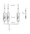
図2には、帯域通過フィルタ・バンク部5−mの内部構成を図解している。同図に示すように、帯域通過フィルタ・バンク部5−mは、それぞれ異なる周波数帯域を受け持つF個の帯域通過フィルタ8−1,8−2,…,8−Fで構成される。各帯域通過フィルタ8−1,8−2,…,8−Fは、例えばデジタル・フィルタで構成される。
【0062】
m番目のマイクロホン2−mからの受信信号に由来する信号x(m;t)は、それぞれ異なる周波数帯域を受け持つF個の帯域通過フィルタ8−1,8−2,…,8−Fによりフィルタリングされることにより、帯域別のF個の信号x(m,f;t)(f=1,2,…,F)に分解されて出力される。
【0063】
図3には、相互相関関数計算部6の内部構成を図解している。同図では、相互相関関数係数部6のうち、m番目のマイクロホン5−mとn番目のマイクロホン5−nの各々からの受信信号間の相互相関関数を計算する部分を抽出して図解している。
【0064】
m番目のマイクロホン2−mとn番目のマイクロホン2−nの各々からの受信信号におけるf番目の周波数帯域の各帯域別信号x(m,f;t)及びx(n,f;t)(m=1,2,…,M−1;n=m+1,m+2,…,M;f=1,2,…,F)は、それぞれT個の遅延器91,9−2,…,9−T、及び10−1,10−2,…,10−Tに順次入力される。
【0065】
特定量の遅延を受けたこれら2つの信号は、積算器11−1,11−2,…,11−(2T+1)により掛け合わされ、さらに低域通過フィルタ12−1,12−2,…,12−(2T+1)に入力され、重み付き時間平均され、その結果がf番目の周波数帯域のm番目とn番目のマイクロホン2−m及び2−nからの帯域別信号の各時間後とに2T+1個の値からなる相互相関関数r(m,n,f;t;d)(t=1,2,…,;d=−T−t+1,…,T)として出力される。
【0066】
遅延器の個数Tは、m番目とn番目の各マイクロホン2−m,2−n間の距離をD(m,n)、信号の速さをcとおいたとき、サンプリング周期を時間の単位とすれば、T〜D(m,n)/cとなるように選ばれる。後の過程における処理を単純化するなどの目的のために、Tより多くの遅延器を設けてもよい。但し、その場合はマイクロホン間の距離D(m,n)を信号が進む時間D(m,n)/cより長い遅延を与えることになり、物理的には冗長である。
【0067】
次いで、信号源方向又は位置推定部7の内部構成及び動作特性について説明する。但し、後述するようにマイクロホンの個数Mが2の場合と3以上の場合とでは内部構成と動作は相違する。
【0068】
図4には、マイクロホンの個数Mが2の場合における信号源方向又は位置推定部7の内部構成を図解している。
【0069】
同図に示す場合、2つの異なるマイクロホンの組は参照番号1−1と1−2のマイクロホンによる一組だけであるので、信号源方向又は位置推定部7への入力はF個の相互相関関数r(1,2,f;t;d)(f=1,2,…,F)である。これらの相互相関関数は、規格化計算部13により周波数帯域ごとに規格化され、規格化相互相関関数rn(1,2,f;t;d)(f=1,2,…,F)として出力される。
【0070】
規格化相互相関関数rn(1,2,f;t;d)は、相互相関関数r(1,2,f;t;d)の遅延時間dに関して最大値又は分散などの値を求め、これらの値によりその相互相関関数r(1,2,f;t;d)を割り算して計算することができる。
【0071】
次いで、規格化相互相関関数rn(1,2,f;t;d)(f=1,2,…,F)は、加算部14に入力され、それらのフィルタの番号fについて加算した値が加算相互相関関数R(1,2;t;d)として出力される。
【0072】
この加算においては、通常はすべてのフィルタ番号について加算することが望ましい。あるいは、事前に信号や雑音が含まれる周波数帯域が知られている場合には、信号が含まれる若しくは雑音が含まれない、一部の複数の周波数帯域に対応する番号についてのみ加算してもよいし、あるいは信号による成分を強調して雑音による成分を抑制するように重み付き加算してもよい。
【0073】
次いで、加算相互相関関数R(1,2;t;d)は、極大検出部15に入力され、遅延時間dに関して極大値を与える遅延時間d(1,2;1),d(1,2;2),…が検出され、出力される。
【0074】
この極大検出においては、信号源に対応しない意味のない極大を検出することを抑制するため、あらかじめ設定されるか、あるいは加算相互相関関数R(1,2;t;d)の、平均や分散などの統計的数値によって設定される閾値に、その極大値が達している、あるいはその閾値を越えていることを条件として、極大の検出を行うようにしてもよい。
【0075】
次いで、上記の遅延時間d(1,2;1),d(1,2;2),…は信号源方向又は位置推定部16に入力され、それぞれの遅延時間に対応する信号源の方向θ1,θ2,…が以下の式により計算され、出力される。
【0076】
【数1】
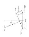
図5には、信号源方向推定に用いられる上式[数1]を図解している。但し、2つのマイクロホン2−1と2−2と信号源1−iを通る平面内で説明する。
【0078】
マイクロホンが2つの場合、信号源の位置を遅延時間d(1,2;i)から推定することは数学的に不可能であり、その方向を推定することだけができる。この場合、信号源は2つのマイクロホン間の距離D(1,2)に比べて充分に離れた位置にあり、信号は平面波で記述されるものと近似される。
【0079】
図5に示すようなマイクロホン2−1と2−2の作る直線に垂直な方向を基準として信号源1−iがθiの方向にあるものとする。このとき、θiの符号は信号源がマイクロホン2−1側にある場合を正方向、マイクロホン2−2側にある場合を負方向と定義する。したがって、図5に示す例ではθi>0である。
【0080】
図5に示す例では、信号の速さをcと置くと、信号源1−iからの信号は、マイクロホン2−1に先に到達し、マイクロホン2−2にはD(1,2)sinθi/cだけ遅れて到達する。
【0081】
したがって、マイクロホン2−1及び2−2によって受信した信号x(1;t)及びx(2;t)のうち信号源1−iに由来する成分をそれぞれxs(1,i;t)及びxs(2,i;t)と定義すると、時間遅れに着目し振幅の違いを無視すると、以下の式が成立する。
【0082】
【数2】
加算相互相関関数R(1,2;t;d)の極大として検出された遅延時間d(1,2;i)が信号源1−iに対応するものとすれば、
【0084】
【数3】
となるから、これを変形して上式[数1]を得ることができる。
【0086】
なお、雑音による影響やサンプリングによる影響のためc・d(1,2;i)/D(1,2)の絶対値|c・d(1,2,i)/D(1,2)|が1を越え、そのarcsinが実数の範囲内では求められない事態が起こり得る。この場合は、d(1,2;i)が正のとき、θi=π/2=90゜、d(1,2;i)が負のときθi=−π/2=−90゜と推定して差し支えない。
【0087】
次に、マイクロホンの個数Mが3以上の場合について、信号源方向又は位置推定部7の内部構成及び動作について、図6を参照しながら説明する。
【0088】
マイクロホンの個数が2の場合(図4を参照のこと)と同様に、相互相関関数r(m,n,f;t;d)(m=1,2,…,M−1;n=m+1,m+2,…,M;f=1,2,…,F)は規格化計算部13に入力され、周波数帯域ごとに規格化され、規格化相互相関関数rn(m,n,f;t;d)(m=1,2,…,M−1;n=m+1,m+2,…,M;f=1,2,…,F)として出力される。
【0089】
規格化相互相関関数rn(m,n,f;t;d)は、相互相関関数r(m,n,f;t;d)の遅延時間dに関して最大値又は分散等の値を求め、これらの値によりその相互相関関数r(m,n,f;t;d)を割り算して計算する。
【0090】
次いで、規格化相互相関関数rn(m,n,f;t;d)(m=1,2,…,M−1;n=m+1,m+2,…,M;f=1,2,…,F)は、加算部14に入力され、それらをフィルタの参照番号fについて加算した値が加算相互相関関数R(m,n;t;d)(m=1,2,…,M;n=m+1,m+2,…,M)として出力される。
【0091】
加算部14での加算においては、通常は、すべてのフィルタ番号について加算することが望ましい。あるいは、事前に信号や雑音が含まれる周波数帯域が知られている場合には、信号が含まれる若しくは雑音が含まれない、一部の複数の周波数帯域に対応する番号についてのみ加算してもよいし、あるいは信号による成分を強調し雑音による成分を抑制するように重み付き加算してもよい。
【0092】
次いで、加算相互相関関数R(m,n;t;d)(m=1,2,…,M;n=m+1,m+2,…,M)は、極大検出部15に入力され、遅延時間dに関して極大値を与える遅延時間d(m,n;1),d(m,n;2),…(m=1,2,…,M;n=m+1,m+2,…,M)が検出され、出力される。
【0093】
この極大検出においては、信号源に対応しない意味のない極大を検出することを抑制するため、あらかじめ設定される、あるいは加算相互相関関数R(m,n;t;d)の平均や分散などの統計的数値によって設定される閾値を、その極大値が達しているあるいは越えていることを条件として、極大値の検出を行うようにしてもよい。
【0094】
次いで、上記の遅延時間d(m,n;i)(m=1,2,…,M−1;n=m+1,m+2,…,M;i=1,2,…)は、信号源位置推定部17に入力され、それぞれの遅延時間に対応する信号源のS(1)=(Sx(1),Sy(1),Sz(1)),S(2)=(Sx(2),Sy(2),Sz(2)),…が計算され、出力される。
【0095】
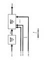
図7には、信号源位置推定部17の内部構成を示している。
【0096】
上記の遅延時間d(m,n;i)(m=1,2,…,M−1;n=m+1,m+2,…,M;i=1,2,…)は、遅延時間分析部18に入力され、推定される信号源ごとに集合E(k)={d(m1,m2;k),d(m1,m3;k),…,d(m2,m3;k),…,d(mi,mj;k)}(k=1,2,…)に分類される。
【0097】
このとき、遅延時間d(m,n;i)の異なる遅延時間を区別する番号iを適宜入れ替え、異なる上記推定される信号源を区別する番号kに一致するようにした。この分類は、ある1つの信号源に対応する集合E(k)から、相異なる3つのマイクロホンの組(n1,n2,n3)(但し、n1<n2<n3とする)の要素から作られる3つの相異なる2つのマイクロホンの組(n1,n2),(n1,n3),(n2,n3)の受信信号間の遅延時間d(n1,n2;k),d(n1,n3;k),d(n2,n3;k)を任意に選んだときに、次の条件式が満たされるように行われる。
【0098】
【数4】
ここで、|a|はaの絶対値を表し、εは1,2,3程度の小さな数に選ばれる。
【0100】
上記の分類を行うには、例えば、すべての相異なるマイクロホンの番号の組(n1,n2,n3)(1≦n1<n2<n3≦M)について、上式[数4]を満たす遅延時間の組を順次探索し、さらに、共通する遅延時間を含む組を併合して、その共通する遅延時間を取り除く手続を繰り返せばよい。
【0101】
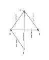
図8には、上式[数4]を説明するための図を示している。
【0102】
信号源1−kがS(k)に位置するものとし、そこから発生する信号が、位置Mn1,Mn2,Mn3にそれぞれ位置するマイクロホン2−n1,2−n2,2−n3の各々に到達すると、これらに要する時間はそれぞれ、tn1(k)=|S(k)−Mn1|/c,tn2(k)=|S(k)−Mn2|/c,tn3(k)=|S(k)−Mn3|/c,となる。ここで、|A|は、ベクトルAの大きさである。
【0103】
遅延時間d(ni,nj:k)(ni,nj=n1,n2,n3)は、d(ni,nj;k)=tnj(k)−tni(k)となる。これを上式[数4]の左辺に代入すると0になることが分かる。
【0104】
遅延時間d(ni,nj:k)(ni,nj=n1,n2,n3)の推定において、雑音による影響やサンプリングによる影響のために生じる誤差により、上式[数4]の左辺の値が厳密には0にならない場合があることを考慮して、ある小さな値εよりも小さければ、同一の信号源kによるものであると判定することにしたものが[数4]である。
【0105】
次に、上記の信号源ごとに分類された遅延時間の集合E(k)(k=1,2,…)は、信号源位置計算部19に入力され、信号源の位置S(k)=(Sx(k),Sy(k),Sz(k))(k=1,2,…)が計算され、出力される。
【0106】
信号源源位置の計算方法の1つは、i番目のマイクロホン1−iの位置をMi=(Mxi,Myi,Mzi)とおいて、E(k)の各要素d(mi,mj;k)について、それぞれ[|Mmj−S(k)|/c−|Mmi−S(k)|/c−d(mi,mj;k)]の2乗を計算して、これらをすべて足し合わせた量を最小化するS(k)を求めることである。
【0107】
次いで、このような信号源位置の計算方法によりS(k)が正しく計算される理由について説明する。
【0108】
信号源1−kからの信号が、マイクロホン2−mi,2−mjの各々に到達するのに、それぞれtmi(k),tmj(k)だけの時間を要するとすると、tmi(k)=|Mmi−S(k)|/c,tmj(k)=|Mmj−S(k)|/cである。
【0109】
マイクロホン2−mi,2−mj間の遅延時間d(mi,mj;k)は、雑音による影響やサンプリングによる影響のために生じる誤差がなければ、d(mi,mj;k)=tmj(k)−tmi(k)=|Mmj−S(k)|/c−|Mmi−S(k)|/cとなる。
【0110】
雑音による影響やもサンプリングによる影響のために生じる誤差を考慮して、このような誤差の2乗をすべてのE(k)の要素である遅延時間に関して足し合わせた量をS(k)に関して最小化すれば、最小自乗誤差基準に基づいて最適なS(k)の推定値が得られる。
【0111】
なお、上述した信号源位置推定において、マイクロホンの個数Mが3の場合、空間的に任意の位置に存在する信号源の位置を推定することは数学的に不可能である。このため、信号源が存在する平面を仮定して、これを信号源の位置に関する拘束条件として位置を推定すればよい。この場合、計算が正しく行われるためには、この信号源が存在すると仮定する平面は、3つのマイクロホンがその上に存在する平面に対して垂直に交じらないものを選ぶ必要があり、例えば、3つのマイクロホンがその上に存在する平面を選べばよい。
【0112】
[第2の実施例]
図9には、本発明の第2の実施例に係る信号処理装置の構成を模式的に示している。
【0113】
同図に示すように、この信号処理装置は、1以上の信号源1−1,1−2…から発生する信号を受信する複数(M個)のマイクロホン2−1,2−2,…,2−Mと、各マイクロホン2−1…の受信信号を増幅する増幅器3−1,3−2,…,3−Mと、各増幅信号をデジタル変換するA/D変換器4−1,4−2,…,4−Mと、帯域通過フィルタ・バンク5−1,5−2,…,5−Mとからなる複数(M系統)の受信系統と、対応する周波数帯域ごとに受信系統の組み合わせごとに周波数帯域別信号間の相互相関関数を計算する相互相関関数計算部6と、信号源からの信号を強調する信号強調部20とで構成される。
【0114】
マイクロホン2−1,2−2,…,2−Mでそれぞれ受信され、増幅器3−1,3−2,…,3−Mでそれぞれ増幅された受信信号は、A/D変換器4−1,4−2,…,4−Mによりデジタル変換されて、デジタル受信信号x(m;t)を得る。ここで、m(=1,2,…,M)は、マイクロホンを識別するための参照番号であり、また、t(=1,2,…)は信号が劣化しないように選ばれたサンプリング周期を単位とする時刻である。
【0115】
次いで、デジタル変換された各受信信号x(m,t)は、それぞれ対応する帯域通過フィルタ・バンク部5−m(m=1,2,…,M)に入力される。帯域通過フィルタ・バンク部5−mは、それぞれ複数の帯域通過フィルタで構成されて、増幅及びデジタル変換された受信信号を複数の周波数帯域別信号に分解することができる。ここでは、F(>1)個の帯域別信号x(m,1;t),x(m,2;t),…,x(m,F;t)に分解されて出力されるものとする。Fは、各フィルタ・バンク部のバンク数である。
【0116】
次いで、M×F個の帯域別信号x(m,f;t)(m=1,2,…,M;f=1,2,…,F)は相互相関関数計算部6に入力される。相互相関関数計算部6では、異なる2つのマイクロホンの組み合わせ(m,n)ごとに、対応する周波数帯域別の相互相関関数r(m,n,f;t;d)(m=1,2,…,M−1;n=m+1,m+2,…,M;f=1,2,…,F;d=−T,−T+1,…,T)を計算して出力する。ここで、d(=−T,−T+1,…,T)は、x(n,f;t)を基準としてx(m,f,t)を遅延させたと考える遅延時間であり、Tは[006]で既に説明したように、マイクロホンの間隔と信号の速さとサンプリング周期から定める最大遅延時間である。
【0117】
次いで、算出されたM×(M−1)×F/2個の帯域別相互相関関数r(m,n,f;t;d)(m=1,2,…,M−1;n=m+1,m+2,…,M;t=1,2,…;d=−T,−T+1,…,T)は信号強調部20に入力されて、1つあるいは複数の信号源ごとの信号が強調されて出力される。
【0118】
図9において、図1と同じ参照番号が付された各機能モジュールは略同一の内部構成及び動作特性を備えているので、ここでは説明を省略する。以下では、信号強調部20について、その内部構成と動作特性について説明する。但し、マイクロホンの個数Mが2の場合と3以上の場合とでは内部構成と動作は相違する。
【0119】
図10には、マイクロホンの個数Mが2の場合における信号強調部20の内部構成を図解している。
【0120】
同図に示す場合、2つの異なるマイクロホンの組は参照番号1−1と1−2のマイクロホンによる一組だけであるので、信号源方向又は位置推定部7への入力はF個の相互相関関数r(1,2,f;t;d)(f=1,2,…,F)である。これらの相互相関関数は、規格化計算部13により周波数帯域ごとに規格化され、規格化相互相関関数rn(1,2,f;t;d)(f=1,2,…,F)として出力される。
【0121】
規格化相互相関関数rn(1,2,f;t;d)は、相互相関関数r(1,2,f;t;d)の遅延時間dに関して最大値又は分散などの値を求め、これらの値によりその相互相関関数r(1,2,f;t;d)を割り算して計算することができる。
【0122】
次いで、規格化相互相関関数rn(1,2,f;t;d)(f=1,2,…,F)は、加算部14に入力され、それらのフィルタの番号fについて加算した値が加算相互相関関数R(1,2;t;d)として出力される。
【0123】
この加算においては、通常はすべてのフィルタ番号について加算することが望ましい。あるいは、事前に信号や雑音が含まれる周波数帯域が知られている場合には、信号が含まれる若しくは雑音が含まれない、一部の複数の周波数帯域に対応する番号についてのみ加算してもよいし、あるいは信号による成分を強調して雑音による成分を抑制するように重み付き加算してもよい。
【0124】
次いで、加算相互相関関数R(1,2;t;d)は、極大検出部15に入力され、遅延時間dに関して極大値を与える遅延時間d(1,2;1),d(1,2;2),…が検出され、出力される。
【0125】
この極大検出においては、信号源に対応しない意味のない極大を検出することを抑制するため、あらかじめ設定されるか、あるいは加算相互相関関数R(1,2;t;d)の、平均や分散などの統計的数値によって設定される閾値に、その極大値が達している、あるいはその閾値を越えていることを条件として、極大の検出を行うようにしてもよい。
【0126】
極大検出部15で検出された、遅延時間d(1,2;1),d(1,2;2),…と、帯域通過フィルタ・バンク部5−1,5−2で分解された帯域別信号x(m,f;t)(m=1,2,…,F)とは、強調信号生成部21に入力され、強調信号y(1;t),y(2;t),…が、遅延器と加算器を用いた遅延加算により計算されて出力される。
【0127】
上記の強調信号y(i;t)(i=1,2,…)は、例えば、図示しない遅延器により遅延時間d(1,2;k)に応じて、帯域別信号x(m,f;t)(m=1,2;f=1,2,…,F)をそれぞれx(1,f;t−T/2−d(1,2;i)/2),x(2,f;t−T/2+d(1,2;i)/2)のように遅延し、さらに、図示しない加算器により、以下の加算を計算すればよい。すなわち、
【0128】
【数5】
上記の加算においては、遅延させた帯域別信号x(m,f;t)(m=1,2;f=1,2,…,F)を、同じ重みで加算しているが、例えばd(1,2;i)やr(1,2,f;t;d(1,2;i))の値に応じて適当な重みを乗じて加算したりしてもよい。
【0130】
また、図11には、マイクロホンの個数Mが3以上の場合における信号強調部20の内部構成を図解している。
【0131】
マイクロホンの個数が2の場合(図10を参照のこと)と同様に、相互相関関数r(m,n,f;t;d)(m=1,2,…,M−1;n=m+1,m+2,…,M;f=1,2,…,F)は規格化計算部13に入力され、周波数帯域ごとに規格化され、規格化相互相関関数rn(m,n,f;t;d)(m=1,2,…,M−1;n=m+1,m+2,…,M;f=1,2,…,F)として出力される。
【0132】
規格化相互相関関数rn(m,n,f;t;d)は、相互相関関数r(m,n,f;t;d)の遅延時間dに関して最大値又は分散等の値を求め、これらの値によりその相互相関関数r(m,n,f;t;d)を割り算して計算する。
【0133】
次いで、規格化相互相関関数rn(m,n,f;t;d)(m=1,2,…,M−1;n=m+1,m+2,…,M;f=1,2,…,F)は、加算部14に入力され、それらをフィルタの参照番号fについて加算した値が加算相互相関関数R(m,n;t;d)(m=1,2,…,M;n=m+1,m+2,…,M)として出力される。
【0134】
加算部14での加算においては、通常は、すべてのフィルタ番号について加算することが望ましい。例えば、事前に信号や雑音が含まれる周波数帯域が知られている場合には、信号が含まれる若しくは雑音が含まれない、一部の複数の周波数帯域に対応する番号についてのみ加算してもよいし、あるいは信号による成分を強調し雑音による成分を抑制するように重み付き加算してもよい。
【0135】
次いで、加算相互相関関数R(m,n;t;d)(m=1,2,…,M;n=m+1,m+2,…,M)は、極大検出部15に入力され、遅延時間dに関して極大値を与える遅延時間d(m,n;1),d(m,n;2),…(m=1,2,…,M;n=m+1,m+2,…,M)が検出され、出力される。
【0136】
この極大検出においては、信号源に対応しない意味のない極大を検出することを抑制するため、あらかじめ設定される、あるいは加算相互相関関数R(m,n;t;d)の平均や分散などの統計的数値によって設定される閾値を、その極大値が達しているあるいは越えていることを条件として、極大値の検出を行うようにしてもよい。
【0137】
極大検出部15で検出された遅延時間d(1,2;1),d(1,2;2),…と、帯域通過フィルタ・バンク部5−1,5−2,…,5−Mで分解された帯域別信号x(m,t;t)(m=1,2,…,M;f=1,2,…,F)とは、強調信号生成部22に入力され、強調信号y(1;t),y(2;t),…が、置換器と加算器を用いた遅延加算により計算されて出力される。
【0138】
図12には、この強調信号生成部22の内部構成を図解している。
【0139】
上記の遅延時間d(m,n;i)(m=1,2,…,M−1;n=m+1,m+2,…,M;i=1,2,…)は、遅延時間分析部18に入力され、推定される信号源ごとに集合E(k)=d(m1,m2;k),d(m1,m3;k),…,d(m2,m3;k),…,d(mi,mj;k)(k=1,2,…)に分類される。
【0140】
このとき、遅延時間d(m,n;i)の異なる遅延時間を区別する番号iを適宜入れ替え、異なる上記推定される信号源を区別する番号kに一致するようにした。この分類は、ある1つの信号源に対応する集合E(k)から、相異なる3つのマイクロホンの組(n1,n2,n3)(但し、n1<n2<n3とする)の要素から作られる3つの相異なる2つのマイクロホンの組(n1,n2),(n1,n3),(n2,n3)の受信信号間の遅延時間d(n1,n2;k),d(n1,n3;k),d(n2,n3;k)を任意に選んだときに、上述した条件式[数4]が満たされるように行われる。
【0141】
次いで、信号源ごとに分類された遅延時間の集合E(k)(k=1,2,…)と、各帯域通過フィルタ・バンク部5−1,5−2,…,5−Mで分解された帯域別信号x(m,f;t)(m=1,2,…,M;f=1,2,…,F)とは、強調信号計算部22に入力され、強調信号y(1;t),y(2;t),…が計算され、出力される。
【0142】
図13には、この強調信号計算の方法の一例を図解している。同図に示す例では、E(k)={d(m1,m2;k),d(m2,m3;k),d(m2,m4;k),d(m3,m4;k)}(m1<m2<m3<m4)である。このとき、マイクロホン2−miの番号miを頂点miに割り当て、異なる2つのマイクロホン番号i<jに対して、d(i,j;k)がE(k)の要素であれば、iを始点とし、jを終点とする有向線分を表す矢印を描いたものが、図13に示すグラフである。
【0143】
第1の実施例において説明した信号源ごとに分類された遅延時間の集合E(k)(k=1,2,…)を求める手続に従えば、グラフは必ず連結したもの、すなわちグラフの任意の2つの頂点はいくつかの有向成分により繋がったものになる。
【0144】
頂点を1つ選び(図示の例ではm1を選択したものとする)、各頂点mi(i=1,2,3,4)に対して、遅延量zmi(k)を次のように計算する。
【0145】
すなわち、m1から有向線分d(i,j;k)をたどって、miに至る経路を1つ選び、その経路に従ってd(i,j;k)の値を加算する。この加算の際、経路を進む向きと有向線分の向きが同じであれば−1を、反対であれば+1を重みとして乗じて加算を行う。図示の例では、以下に示す式の通りとなる。すなわち、
【0146】
【数6】
上述の遅延量zmi(k)の計算においては、1つの経路を選んで計算を行っているが、複数の経路について計算を行い、それらの平均を適当に計算して、これを遅延量zmi(k)として用いてもよい。
【0148】
次いで、zmi(k)が正又は0になるように、すべてのzmi(k)に等しくある数Z(k)を加えたものを改めてzmi(k)とする。図示の場合、
【0149】
【数7】
最後に、これらの遅延量を用いて、図示しない遅延器によりx(mi,f;t)をそれぞれ遅延し、さらに図示しない加算器により、
【0151】
【数8】
と加算され、遅延加算された強調信号y(k;t)が計算される。
【0153】
上記の遅延加算により、信号源1−kからの信号がマイクロホン2−m1,2−m2,2−m3,2−m4に到達するのに要する時間の差が、遅延量zm1(k),zm2(k),zm3(k),zm4(k)による遅延により補償され、同時刻に発せられた信号として加算されることは、その計算方法から明らかである。
【0154】
また、上記の強調信号計算方法の他の例では、第1の実施例において説明したものと同様の方法により、信号源位置推定法により各信号源の位置S(k)(k=1,2,…)を推定し、この推定信号源位置S(k)と各マイクロホンの位置Mi(i=1,2,…,M)とから計算される遅延時間zi(k)=|S(k)−Mi|/cを用いて、帯域通過フィルタ・バンク部5−1,5−2,…,5−Mで分解された帯域別信号x(m,f;t)(m=1,2,…,M;f=1,2,…,F)を、以下の計算式に従い、遅延加算により強調信号y(k;t)を計算することができる。すなわち、
【0155】
【数9】
上記の2通りの強調信号計算の方法における遅延加算においては、加算される遅延させた帯域別信号x(m,f;t)(m=1,2,…,M;f=1,2,…,F)を、すべて同じ重みで加算しているが、例えばd(mi,mj;k)の値に応じて適当な重みを乗じて計算したり、あるいはr(mi,mj,f;;t;d(mi,mj;k))の値に応じて適当な重みを乗じて加算したりしてもよい。
【0157】
以下では、本実施例に係る信号源方向又は位置推定装置、並びに信号強調装置の適用例を挙げておく。
【0158】
(適用例1)
信号源方向又は位置推定装置のTV会議システム、監視システムへの適用:
複数のマイクを含んだ信号源方向又は位置推定装置の出力をカメラ制御装置に接続する(図14を参照のこと)ことで、カメラを常時信号源に向けることができる。あるいは、カメラ制御装置に複数台のカメラが接続されている場合には、信号源方向又は位置推定装置の出力をモニタすべきカメラを逐次切り替えるようにしてもよい。または、信号源の位置推定とともに、信号源に向かってカメラをズームインさせるようにしてもよい。
【0159】
(適用例2)
信号強調装置の入力装置への適用:
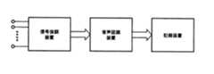
本発明に係る信号強調装置を、コンピュータや携帯端末(PDA)などの情報処理装置におけるキーボードその他のユーザ入力装置の代替とすることができる。すなわち、複数のマイクを含んだ信号強調装置の出力を音声認識装置で音声認識処理することによって(図15を参照のこと)、情報処理装置に対するキャラクタ形式のコマンド入力とすることができる。また、音声ベースでのユーザインターフェースにすることもできる。
例えば、話者ごとの発言内容を記録装置に記録することによって議事録作成システムを構築することができる。
【0160】
(適用例3)
信号強調装置のコマンダ/コントローラへの適用:
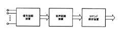
本発明に係る信号強調装置を、ロボット、自動車、コンピュータ、携帯端末(PDA)、各種の情報家電機器に対して、ユーザ操作を行うコマンダ/コントローラとして適用することができる。すなわち、複数のマイクを含んだ信号強調装置の出力を音声認識装置で音声認識処理してキャラクタに変換し、さらに入力キャラクタをコマンド解析装置により解析処理することによって(図16を参照のこと)、ユーザのコマンド内容を特定することができる。
例えば、このようなコマンダ/コントローラを介して、ロボットに対して「歩行」やその他の動作指示を行うことができる。また、コンピュータに対して、「ワープロ」と話しかけることにより、該当するアプリケーションを起動させたり、さらにキャラクタ入力を行うことができる。また、PDAのような個人情報を扱う携帯端末に対して、「今日の予定は?」と話しかけることによりスケジュール帳を起動して該当する日付や時刻の予定を引き出すことができる。また、電話に対して、「○△さんに電話をかけて」と話しかけることにより、電話帳を検索して該当する人物に対して発呼することができる。また、情報家電に対して、「部屋の温度を上げて」とか「××を録画して」などの操作を指示することができる。また、カーナビゲーション・システムに対して「○△宅まで行きたい」と話しかけることにより、道案内を起動することができる。
【0161】
(適用例4)
信号強調装置、並びに信号源方向又は位置推定装置のTV会議システムへの適用:
複数のマイクを含んだ信号強調装置の出力を音声認識装置に入力し、さらに音声入力結果を記録・表示装置に出力するとともに、複数のマイクを含んだ信号源方向又は位置推定装置による信号源の方向又は位置の推定結果を記録・表示装置に出力する(図17を参照のこと)。
【0162】
記録・表示装置では、何処の席にいる人がどのような発言を行ったかを逐次的に記録したり、現在発言中の人を特定して、カメラで追跡して画面表示したりすることができる。
【0163】
(適用例5)
スマート・アンテナへの適用:
複数のアンテナを含んだ信号方向又は位置推定装置の出力をアンテナ指向性制御装置に出力するとともに、このアンテナ指向性制御装置の制御指令を基にアンテナの位置や向きなどを調整することができる(図18を参照のこと)。このようなシステムによれば、アンテナの受信感度を自律的且つダイナミックに調整することができる。また、基地局などに配備することによって、携帯電話からの接続状況を向上させることができる。
【0164】
[追補]
以上、特定の実施例を参照しながら、本発明について詳解してきた。しかしながら、本発明の要旨を逸脱しない範囲で当業者が該実施例の修正や代用を成し得ることは自明である。
【0165】
上記の第1の実施例においては、相互相関関数から信号源の方向又は位置を推定する際に、また、第2の実施例においては、相互相関関数と周波数帯域別信号とから信号強調する際に、周波数帯域ごとに相互相関関数を規格化し、受信装置の組み合わせごとにこれらの規格化した相互相関関数を、すべてあるいは一部の複数の周波数帯域にわたって加算し、これらの加算された相互相関関数が極大となる遅延時間を受信装置の組み合わせごとに求め、これらを候補遅延時間としている。但し、上記の規格化を必ずしも必要とする訳ではなく、規格化を行わずに以降の処理を行ってもよい。また、相互相関関数をすべてあるいは一部の複数の周波数帯域にわたって加算することなく、それぞれの相互相関関数が極大となる遅延時間を、受信装置の組み合わせごとに求め、これらを候補遅延時間としてもよいし、あるいは複数の異なる周波数帯域を加算した、複数の加算された相互相関関数が極大となる遅延時間を受信装置の組み合わせごとに求め、これらを候補遅延時間としてもよい。
【0166】
また、上記の第1及び第2の各実施例においては、信号を音として、信号源は音源、受信装置はマイクロホンとしているが、信号は他のもの、例えば光、電磁波、水面波などであっても本発明を好適に適用することができる。また、これらの信号の場合は、信号源はそれぞれの信号を発する物又は装置であり、受信装置はそれぞれの信号を受信可能な装置を用いた構成とすればよい。
【0167】
また、上記の第1及び第2の各実施例においては、ディジタル信号処理技術を用いて実現しているが、信号源の種類、用いることのできるハードウェアなどの条件に応じて、その一部あるいは全部をアナログ信号処理技術や、計算機による処理技術によって置き換えることができることは言うまでもない。
【0168】
要するに、例示という形態で本発明を開示してきたのであり、限定的に解釈されるべきではない。本発明の要旨を判断するためには、冒頭に記載した特許請求の範囲の欄を参酌すべきである。
【0169】
【発明の効果】
以上詳記したように、本発明によれば、存在する方向や位置があらかじめ知られていない1あるいは複数の信号源からの信号を複数の受信装置で受信した信号を用いて、信号源の方向又は位置を推定することができる、優れた信号源方向又は位置推定方法及び装置を提供することができる。
【0170】
また、本発明によれば、存在する方向や位置があらかじめ知られていない1あるいは複数の信号源からの信号を、複数の受信装置で受信した信号を用いて強調することができる、優れた信号強調方法及び装置を提供することができる。
【0171】
本発明によれば、1あるいは複数の信号源からの信号を複数の受信装置で受信した各受信信号を、複数の帯域通過フィルタによりそれぞれ複数の周波数帯域別信号に分解して、これら周波数帯域別信号間の相互相関関数を相当する周波数帯域ごとに受信装置の組合せごとに計算して、これらの相互相関関数を基に信号源の方向又は位置を推定するようにしたので、雑音の多い環境や複数の信号源が同時に信号を発生している場合においても信号源の方向又は位置を充分に推定することができる。
【0172】
また、本発明では、1あるいは複数の信号源からの信号を複数の受信装置で受信した各受信信号を、複数の帯域通過フィルタによりそれぞれ複数の周波数帯域別信号に分解し、これら周波数帯域別信号間の相互相関関数を相当する周波数帯域ごとに受信装置の組合せごとに計算して、これらの相互相関関数を基に信号源の方向又は位置と受信装置の配置とによって定まる各受信装置ごとの遅延時間を推定し、この推定遅延時間を用いて各受信信号の周波数帯域別信号をそれぞれ遅延し、これらの遅延した周波数帯域別信号を加算して、信号源の信号を強調するようにしたので、雑音の多い環境や複数の信号源が同時に信号を発生しているような場合においても、1あるいは複数の信号源ごとの信号を強調することができる。
【図面の簡単な説明】
【図1】本発明の第1の実施例に係る信号処理装置の構成を模式的に示したブロック図である。
【図2】帯域通過フィルタ・バンク部5−mの内部構成を示したブロック図である。
【図3】相互相関関数計算部6の内部構成を示したブロック図である。
【図4】マイクロホンの個数Mが2の場合における信号源方向又は位置推定部7の内部構成(第1の実施例)を示したブロック図である。
【図5】信号源方向推定に用いられる式[数1]を解説するための図である。
【図6】マイクロホンの個数Mが3以上の場合における信号源方向又は位置推定部7の内部構成(第1の実施例)を示したブロック図である。
【図7】信号源位置推定部の内部構成を示したブロック図である。
【図8】[数4]を説明するための図である。
【図9】本発明の第2の実施例に係る信号処理装置の構成を模式的に示したブロック図である。
【図10】マイクロホンの個数Mが2の場合における信号源方向又は信号強調部20の内部構成(第2の実施例)を示したブロック図である。
【図11】マイクロホンの個数Mが3以上の場合における信号強調部20の内部構成(第2の実施例)を示したブロック図である。
【図12】強調信号生成部22の内部構成を示したブロック図である。
【図13】強調信号計算の方法の一例を説明するための図である。
【図14】信号源方向又は位置推定装置をTV会議システムや監視システムに適用した例を説明するための図である。
【図15】信号強調装置を入力装置に適用した例を説明するための図である。
【図16】信号強調装置をコマンダ/コントローラに適用した例を説明するための図である。
【図17】信号源方向又は位置推定装置と信号強調装置をTV会議システムに適用した例を説明するための図である。
【図18】信号源方向または位置推定装置をスマート・アンテナに適用した例を説明するための図である。
【符号の説明】
1…音源,2…マイクロホン
3…増幅器,4…A/D変換器
5…帯域通過フィルタ・バンク
6…相互相関関数計算部
7…信号源方向又は位置推定部
8…帯域通過フィルタ
9,10…遅延器
11…積算器,12…重み付き平均低域通過フィルタ
13…規格化計算部,14…加算部
15…極大検出部,16…信号源方向推定部
17…信号源位置推定部
18…遅延時間分析部,19…信号源位置計算部
20…信号強調部
21,22…強調信号生成部
23…強調信号計算部[0001]
BACKGROUND OF THE INVENTION
The present invention relates to a signal source direction or position estimation method and apparatus for estimating a direction or position in which a signal source such as a sound source exists, and in particular, based on a cross-correlation function between received signals received by a plurality of receiving apparatuses. The present invention relates to a signal source direction or position estimation method and apparatus for estimating the direction and position of one or a plurality of signal sources.
[0002]
The present invention also relates to a signal enhancement method and apparatus for enhancing signals of one or a plurality of signal sources based on a cross-correlation function between received signals received by a plurality of reception devices.
[0003]
[Prior art]
In a noisy environment or an environment where multiple signal sources are generating signals at the same time, the technology for estimating the direction and position of a signal source is to use a receiving device to better receive the signal from the signal source. Adapted systems, systems that automatically monitor the video camera in the direction of the signal source, video conferencing systems that automatically point the video camera in the direction of the speaker and transmit the video of the speaker Used.
[0004]
In the technical field of such signal processing, it is conventionally performed to receive a transmission signal using a plurality of receiving devices and estimate the direction and position of the signal source based on a cross-correlation function between the received signals. It has been broken.
[0005]
For example, in Japanese Patent Laid-Open No. 11-83982, a cross-correlation coefficient is obtained by giving a delay time corresponding to an assumed sound source direction angle between outputs of two microphones selected from among a plurality of microphones. A sound source direction detection device that displays a value obtained by adding these values to a sound source direction angle is disclosed. According to the sound source direction detection device described in the publication, it is possible to accurately know the direction of arrival of sound regardless of the type of sound wave even when the SN ratio is poor.
[0006]
Further, in JP-A-11-304906, the cross-correlation function of signals received by a plurality of microphones is calculated for all sets of microphones, and the time difference giving the maximum value of these cross-correlation functions is set as a preliminary estimated time difference. Next, a sound source position estimation method for searching for a time difference that maximizes the power of the delay sum for all microphones in the vicinity of the preliminary estimation time difference and calculating the position of the sound source based on the estimated time difference. It is disclosed. The time difference corresponds to the direction angle of the sound source. By adding a delay to each microphone, the reception sensitivity in a specific direction can be increased. The sound source position estimation method described in this publication is excellent in noise resistance and requires a small amount of calculation.
[0007]
In Japanese Patent No. 2982766, only the polarity of a signal whitened by an inverse filter having a coefficient of an autoregressive coefficient calculated from the signal itself or an autoregressive coefficient calculated from the signal is extracted from a plurality of audio signals acquired by a plurality of microphones. Generate code time sequences, calculate cross-correlation functions of these code time sequences, calculate normalized power from these cross-correlation functions, calculate their time average, and estimate sound source direction based on this time average A method and apparatus are disclosed.
[0008]
However, none of the above conventional techniques can sufficiently estimate the direction and position of a signal source when there is a lot of noise or when there are a large number of signal sources that simultaneously generate signals.
[0009]
In Japanese Patent Laid-Open No. 11-304906, a time difference that gives the maximum value of the cross-correlation function is set as a preliminary estimation time difference, and a time difference that maximizes the power of the delay sum is searched in the vicinity, and a sound source position is calculated from the time difference. (Described above). When it is assumed that this method is applied to the estimation of the direction and position of each signal source in an environment where a plurality of signal sources exist, the preliminary estimation time corresponding to each signal source is obtained from the cross-correlation function, It is necessary to search each time difference for increasing the power of the delay sum in the vicinity of each preliminary estimation time. For this reason, the amount of calculation required for the search increases in proportion to the number of signal sources.
[0010]
Also, in Japanese Patent No. 2982766, in order to reduce the hardware scale of the apparatus, a signal time series is obtained by extracting only the polarity of the signal itself or the whitened signal instead of calculating the cross-correlation function of the signal. The sound source direction is estimated based on the cross-correlation function.
[0011]
In the method of extracting the polarity of the signal itself, when a low-frequency noise having a relatively high level is included in the received signal, −1 or +1 is ½ of the period of the noise of the extracted code time sequence. It will be continuous over a period of about one. Therefore, since the code time series corresponds to this low frequency noise rather than the signal of the sound source, the sound source direction cannot be obtained from the cross-correlation function.
[0012]
In addition, when using a method of extracting the polarity of a whitened signal, a characteristic specific to a code from a sound source included in the received signal is lost in the whitening process. For this reason, since the cross-correlation function is strongly influenced by noise, the estimation performance of the sound source direction is deteriorated. As for the whitening method, for example, “Improvement of the performance of cross correlation method for identifying aircraft noise with pre-whitening of signals” (The Journal of the Acoustical Society of Japan, vol.13, no.4, pp. 241-252, July 1992), which was originally targeted at airplane noise measured near the airfield.
[0013]
Japanese Patent No. 2998582 discloses a time difference process in which the output of two microphones is divided into bands, the signal power is obtained for each frequency band, the peak is held, and the logarithm is calculated. A sound source direction estimating method is disclosed in which a cross-correlation function for each frequency band corresponding to the signal obtained is obtained, a cross-correlation function for each band is weighted and averaged, and a sound source direction is calculated from a time difference taking the maximum value.
[0014]
According to the method described in the publication, the sound source direction can be estimated based on the direct sound even in an environment with a lot of reflected sounds. However, according to this method, a large amount of calculation is required for logarithmic calculation of each frequency band of the input signal from each microphone, and the hardware for realizing this is increased in scale. In addition, when the signal power is relatively small or the noise power is relatively large, the influence of the reflected sound may not be reduced by logarithmic processing. For example, if the power of the background noise is 1, a direct sound with a power of 2 arrives, and then a reflected sound with a power of 3 arrives, the background noise is 3.0 dB in the logarithmized numerical value. The reflected sound is 4.7 dB. Accordingly, the magnitude of the reflected sound is 1.5 times that of the direct sound before the logarithmic process, but 1.57 times after the logarithmic process, and the influence of the reflected sound is not reduced numerically./ * / .
[0015]
In a noisy environment or an environment where multiple signal sources generate signals at the same time, the effects of noise and signals from other signal sources are suppressed, and the signal from one signal source is emphasized. When the signal is speech, the separation technology can improve the recognition performance of the speech recognition device, or compare the received signal with the signal measured in advance for each expected signal source type. It is used for the purpose of enhancing the discrimination performance of the signal source discrimination device that performs identification.
[0016]
In the field of such signal enhancement / separation technology, signals are received by a plurality of receiving devices, and each reception determined by the direction or position of the signal source and the position of the receiving device based on a cross-correlation function between the received signals. A delay time for each device is estimated, and each received signal is delayed using the estimated delay time and then added to emphasize or separate a signal from a signal source.
[0017]
For example, in Japanese Patent Laid-Open No. 5-95596, each audio signal received by a plurality of microphones is decomposed by frequency band by a band-pass filter, and a cross-correlation function between signals by frequency band is obtained. There is disclosed a noise reduction apparatus that detects a time difference between audio signals from a correlation function and adds the audio signals after delaying the audio signals based on the detected time difference. According to the noise reduction device, the S / N ratio can be improved by synthesizing the input voice signal and enhancing and taking out the voice signal while suppressing noise.
[0018]
Japanese Laid-Open Patent Publication No. 9-251299 discloses an assumed sound source for an input signal from a microphone array composed of a plurality of microphones, by obtaining a band pass waveform for each frequency band by a band pass filter bank for each microphone channel. Band-pass power distribution for each position or direction is obtained by the minimum variance method, etc., and band-pass power distribution for each frequency band is integrated for all frequency bands to estimate the sound source position or direction, Based on this estimated sound source position or direction, a microphone array input type speech recognition device for extracting a corresponding band pass power from a band pass power distribution for each frequency band as a speech parameter and performing speech recognition, and A method is disclosed.
[0019]
In Japanese Patent No. 2928873, a wave detected by a plurality of wave collecting circuits is obtained as a signal component of a signal for each frequency band or its temporal level change, and a mutual signal component for each frequency band is obtained. A correlation function is calculated to obtain a time difference between signal components whose correlation value exceeds a set threshold value, and a signal component in a frequency band in which this time difference is included in a predetermined set delay time is extracted, and the predetermined set delay time is obtained. There is disclosed a signal processing apparatus that outputs a wave component that arrives from a specific position corresponding to each frequency band, or adds these signal components to output a wave component that arrives from a specific position.
[0020]
However, it is assumed that the noise reduction apparatus described in Japanese Patent Laid-Open No. 5-95596 is mainly used for a car phone, and the sound source to be emphasized is a driver's voice, and the signal source is One is assumed. That is, it is not considered that signals from a plurality of sound sources are emphasized, and the approximate position of the sound source is assumed in advance, and therefore processing relating to a sound source at an arbitrary position is not considered. Further, since the emphasized signal is delayed and added as it is, the signal before being decomposed for each frequency band, if there is relatively large noise in a certain frequency band, this cannot be sufficiently suppressed.
[0021]
In the microphone array input type speech recognition apparatus and method described in Japanese Patent Laid-Open No. 9-251299, a band-pass power distribution for each assumed sound source position or direction is obtained by a minimum variance method or the like. However, the minimum variance method is applicable when the number of sound sources is smaller than the total number of microphones constituting the microphone array, and the amount of calculation is large. If the delay sum method is used instead of the minimum variance method, the amount of calculation can be reduced to some extent, but the accuracy of estimating the sound source position or direction is lowered. Therefore, if the number of signal sources and their positions or directions are unknown, prepare as many microphones as possible and apply the minimum dispersion method while changing the assumed signal source positions or directions, or It is necessary to set a plurality of assumed signal source positions or directions and apply the minimum variance method in parallel. The hardware that realizes such processing becomes expensive or extremely large.
[0022]
In addition, the signal processing device described in Japanese Patent No. 2928873 is configured for the purpose of extracting and separating wave components coming from a predetermined position, and the direction or position of the signal source is unknown. When the direction of arrival of the signal is unknown, the point or position of the signal source is estimated and the signal from that direction is extracted, separated, or emphasized is not taken into consideration.
[0023]
To summarize the above, in the conventional technology, the direction and position of the signal source are not known in advance, and when there is a lot of noise, or when the number of signal sources that simultaneously generate signals is large, it is particularly a receiving device. If the number of signal sources is greater than the number of signals, the direction or position of one or more signal sources cannot be estimated with sufficient accuracy, and the signals from one or more signal sources are not sufficient. I couldn't stress.
[0024]
Annotation
*: The “reflected sound” mentioned here includes a continuous direct sound and an incoming reflected sound. Usually, the power of the reflected sound alone does not become larger than the power of the direct sound. If a directional microphone is used, assuming that the direction with high directivity is close to the direction of arrival of the reflected sound and the direction with low directivity is directed to the direction of arrival of the direct sound, the reflected sound alone The power of may be greater than that of direct sound.
[0025]
[Problems to be solved by the invention]
An object of the present invention is to provide an excellent signal source direction or position estimation method and apparatus capable of estimating the direction and position in which a signal source such as a sound source exists.
[0026]
It is a further object of the present invention to estimate the direction or position of a signal source by using signals received by a plurality of receiving devices from one or a plurality of signal sources whose existing directions and positions are not known in advance. It is an object of the present invention to provide an excellent signal source direction or position estimation method and apparatus.
[0027]
A further object of the present invention is to provide an excellent signal enhancement method and apparatus capable of enhancing signals of one or a plurality of signal sources based on a cross-correlation function between received signals received by a plurality of reception devices. Is to provide.
[0028]
A further object of the present invention is to provide an excellent signal capable of enhancing signals from one or a plurality of signal sources whose existing directions and positions are not known in advance using signals received by a plurality of receiving apparatuses. The object is to provide an enhancement method and apparatus.
[0029]
[Means for Solving the Problems]
The present invention has been made in consideration of the above problems, and a first aspect of the present invention is to receive a plurality of received signals obtained by receiving signals from one or a plurality of signal sources via a plurality of receiving devices. A signal processing apparatus or method for processing,
A first means or step for decomposing each received signal into a plurality of signals according to frequency bands;
A second means or step for calculating a cross-correlation function between signals by frequency bands derived from two different receivers for each combination of receivers for each corresponding frequency band;
Normalize the cross-correlation function for each frequency band, and all the cross-correlation functions standardized for each combination of receivers, Or some frequency bands that include signals or noise if the frequency bands that include signal and noise are known in advance Add overThe delay time that maximizes the added cross-correlation function is obtained for each combination of the receiving devices, and is set as the candidate delay time, and each candidate delay time is given most consistently A third means or step for estimating the direction or position of the signal source;
A signal processing apparatus or method comprising:
[0030]
The first means may be composed of a plurality of band pass filters that pass signals of different frequency bands.
[0035]
The signal source may be a sound source.
[0036]
According to a second aspect of the present invention, there is provided a signal processing apparatus or apparatus for processing a signal reproduced from a recording medium on which signals received from one or a plurality of signal sources are received via a plurality of receiving apparatuses. There,
A first means or step for decomposing each regenerated received signal into a plurality of signals by frequency band;
A second means or step for calculating a cross-correlation function between signals by frequency bands derived from two different receivers for each combination of receivers for each corresponding frequency band;
Normalize the cross-correlation function for each frequency band, and all the cross-correlation functions standardized for each combination of receivers, Or some frequency bands that include signals or noise if the frequency bands that include signal and noise are known in advance Add overThe delay time that maximizes the added cross-correlation function is obtained for each combination of the receiving devices, and is set as the candidate delay time, and each candidate delay time is given most consistently A third means or step for estimating the direction or position of the signal source;
A signal processing apparatus or method comprising:
[0037]
The third aspect of the present invention is a signal processing apparatus or method for processing a plurality of received signals obtained by receiving signals from one or a plurality of signal sources via a plurality of receiving apparatuses,
A first means or step for decomposing each received signal into a plurality of signals according to frequency bands;
A second means or step for calculating a cross-correlation function between signals by frequency bands derived from two different receivers for each combination of receivers for each corresponding frequency band;
Normalize the cross-correlation function for each frequency band, and all the cross-correlation functions standardized for each combination of receivers, Or some frequency bands that include signals or noise if the frequency bands that include signal and noise are known in advance Add overThen, the delay time at which the added cross-correlation function is maximized is obtained for each combination of the receiving devices and is set as the candidate delay time, and the direction or position of the signal source that gives each candidate delay time most consistently is estimated, and the estimated Depending on the direction or position of the signal source A third means or step for estimating a delay time for each receiving device;
A fourth means or step for respectively delaying the signal for each frequency band of each received signal using the estimated delay time and adding the delayed signal for each frequency band;
A signal processing apparatus or method comprising:
[0038]
The first means may be composed of a plurality of band pass filters that pass signals of different frequency bands.
[0044]
The signal source may be a sound source.
[0045]
According to a fourth aspect of the present invention, there is provided a signal processing apparatus or method for processing a signal reproduced from a recording medium on which signals received from one or a plurality of signal sources are received via a plurality of receiving apparatuses. There,
A first means or step for decomposing each regenerated received signal into a plurality of signals by frequency band;
A second means or step for calculating a cross-correlation function between signals by frequency bands derived from two different receivers for each combination of receivers for each corresponding frequency band;
Normalize the cross-correlation function for each frequency band, and all the cross-correlation functions standardized for each combination of receivers, Or some frequency bands that include signals or noise if the frequency bands that include signal and noise are known in advance Add overThen, the delay time at which the added cross-correlation function is maximized is obtained for each combination of the receiving devices and is set as the candidate delay time, and the direction or position of the signal source that gives each candidate delay time most consistently is estimated, and the estimated Depending on the direction or position of the signal source A third means or step for estimating a delay time for each receiving device;
A fourth means or step for respectively delaying the signal for each frequency band of each received signal using the estimated delay time and adding the delayed signal for each frequency band;
A signal processing apparatus or method comprising:
[0046]
[Action]
Signals from one or a plurality of signal sources are received by a plurality of receiving devices, and each received signal is decomposed into signals for each frequency band by a plurality of band pass filters. Then, a cross-correlation function between these signals by frequency bands originating from two different receiving apparatuses is calculated for each corresponding frequency band and for each combination of receiving apparatuses. If the power of non-directional noise is large in a certain frequency band, the cross-correlation function in that frequency band does not show a maximum value, so the direction or position of the signal source, or the direction or position of the signal source The influence of this noise can be effectively suppressed when estimating the delay time for each receiving apparatus determined by the arrangement of the receiving apparatus.
[0047]
In addition, even when the power of non-directional noise is large in all frequency bands, in the frequency band where the signal from the signal source exists, the signal will not be canceled by noise within that frequency band. As long as the cross-correlation function of the frequency band has a maximum value in the delay time for each receiving device determined by the direction or position of the signal source and the arrangement of the receiving device, the direction or position of the signal source or the signal source The delay time for each receiving device determined by the direction or position and the arrangement of the receiving devices can be estimated.
[0048]
Also, in the case of directional noise, this is also one of the signal sources, and the delay time for each receiving apparatus determined by the direction or position, or the direction or position and the arrangement of the receiving apparatus can be estimated. it can.
[0049]
Further, in the method of estimating the direction or position of the signal source from the cross-correlation function, or the method of estimating the delay time for each receiving apparatus determined by the direction or position of the signal source and the arrangement of the receiving apparatus, the mutual correlation is performed for each frequency band. Signals with different power levels depending on the frequency band by using a method that standardizes the correlation function and adds these normalized cross-correlation functions for all combinations of receivers over all or part of multiple frequency bands. In this case, the information of the frequency band having a low power level can be effectively used without being disturbed by the signal of another frequency band having a high power level. To improve the accuracy in estimating the delay time for each receiver determined by the direction or position of the signal source and the arrangement of the receiver. Can.
[0050]
Further, by using a method of adding these standardized cross-correlation functions over a plurality of frequency bands for each combination of receiving apparatuses, the delay time at which these added cross-correlation functions are maximized is determined for each combination of receiving apparatuses. Since these are used as candidate delay times, the number of candidate delay times can be reduced compared to a method that does not use addition. That is, it is possible to reduce the amount of calculation when estimating the number and direction or position of the signal sources that most consistently provide these candidate delay times, or to reduce the size of hardware necessary for the calculation.
[0051]
In addition, in the above-described cross-correlation function addition, when a property related to a signal or noise is known in advance, the component due to the signal is emphasized and weighted addition is performed so as to suppress the component due to the noise. Thus, the accuracy in estimating the delay time for each receiving apparatus determined by the direction or position of the signal source or the direction or position of the signal source and the arrangement of the receiving apparatus can be further increased.
[0052]
Further, in the signal enhancement method and apparatus according to the present invention, when adding the delayed signal for each frequency band, the weight for each frequency band is added according to the value of the cross-correlation function between the signals for each frequency band in the estimated delay time. When coefficients are defined and weighted addition is performed using those weight coefficients, there is a disadvantage that distortion occurs, but the influence from noise and other signal sources can be reduced, and emphasis can be made more clearly. it can.
[0053]
Other objects, features, and advantages of the present invention will become apparent from a more detailed description based on embodiments of the present invention described later and the accompanying drawings.
[0054]
DETAILED DESCRIPTION OF THE INVENTION
Hereinafter, embodiments of the present invention will be described in detail with reference to the drawings.
[0055]
[First embodiment]
FIG. 1 schematically shows a functional configuration of a signal processing apparatus according to the first embodiment of the present invention.
[0056]
As shown in the figure, this signal processing apparatus includes a plurality of (M) microphones 2-1, 2-2,... That receive signals generated from one or more signal sources 1-1, 1-2,. 2 -M, amplifiers 3-1, 3-2,..., 3 -M for amplifying received signals of the microphones 2-1..., And A / D converters 4-1 and 4 for digitally converting each amplified signal. .., 4-M and band-pass filter banks 5-1, 5-2,..., 5-M (in the illustrated example, M) receiving systems and corresponding frequency bands And a
[0057]
The signals received by the microphones 2-1, 2-2, ..., 2-M and amplified by the amplifiers 3-1, 3-2, ..., 3-M are respectively converted into A / D converters 4-1. , 4-2,..., 4-M, respectively, to obtain a digital received signal x (m; t). Here, m (= 1, 2,..., M) is a reference number for identifying a microphone, and t (= 1, 2,...) Is a sampling period selected so that the signal does not deteriorate. Is the time in units.
[0058]
Next, each digitally converted received signal x (m, t) is input to a corresponding bandpass filter bank unit 5-m (m = 1, 2,..., M). Each of the band-pass filter bank unit 5-m includes a plurality of band-pass filters and can decompose the amplified and digital-converted received signal into a plurality of frequency band-specific signals. Here, F (> 1) band-specific signals x (m, 1; t), x (m, 2; t), ..., x (m, F; t) are output after being decomposed. To do. F is the number of banks in each filter bank section.
[0059]
Next, M × F band-specific signals x (m, f; t) (m = 1, 2,..., M; f = 1, 2,..., F) are input to the cross-correlation
[0060]
Next, the calculated M × (M−1) × F / 2 band-specific cross-correlation functions r (m, n, f; t; d) (m = 1, 2,..., M−1; n = , M; t = 1, 2,..., d = −T, −T + 1,..., T) are input to the signal source direction or position estimation unit 7 to estimate the direction or position of the signal source. Is output.
[0061]
FIG. 2 illustrates the internal configuration of the band-pass filter / bank unit 5-m. As shown in the figure, the band-pass filter bank unit 5-m is composed of F band-pass filters 8-1, 8-2,. Each of the band-pass filters 8-1, 8-2,..., 8-F is constituted by a digital filter, for example.
[0062]
The signal x (m; t) derived from the received signal from the m-th microphone 2-m is filtered by F band-pass filters 8-1, 8-2,. As a result, F signals x (m, f; t) (f = 1, 2,..., F) for each band are decomposed and output.
[0063]
FIG. 3 illustrates the internal configuration of the cross-correlation
[0064]
Signals x (m, f; t) and x (n, f; t) for each band in the f-th frequency band in the received signals from the m-th microphone 2-m and the n-th microphone 2-n ( m = 1, 2,..., M−1; n = m + 1, m + 2,..., M; f = 1, 2,. T, and 10-1, 10-2,..., 10-T are sequentially input.
[0065]
These two signals that have received a specific amount of delay are multiplied by integrators 11-1, 11-2,..., 11- (2T + 1), and further, low-pass filters 12-1, 12-2,. -(2T + 1) is input and weighted time averaged, and the result is 2T + 1 for each time of the band-by-band signals from the mth and nth microphones 2-m and 2-n in the fth frequency band. Are output as a cross-correlation function r (m, n, f; t; d) (t = 1, 2,...; D = −T−t + 1,..., T).
[0066]
The number T of delay units is defined such that the distance between the m-th and n-th microphones 2-m, 2-n is D (m, n), and the speed of the signal is c. Then, it is selected to be T to D (m, n) / c. More delay devices than T may be provided for the purpose of simplifying the processing in a later process. However, in this case, a delay longer than the time D (m, n) / c for which the signal travels the distance D (m, n) between the microphones is given, which is physically redundant.
[0067]
Next, the internal configuration and operation characteristics of the signal source direction or position estimation unit 7 will be described. However, as will be described later, the internal configuration and operation differ between the case where the number of microphones M is 2 and the case where the number M is 3 or more.
[0068]
FIG. 4 illustrates the internal configuration of the signal source direction or position estimation unit 7 when the number M of microphones is two.
[0069]
In the case shown in the figure, since only two sets of microphones having the reference numbers 1-1 and 1-2 are provided, the input to the signal source direction or position estimation unit 7 is F cross-correlation functions. r (1, 2, f; t; d) (f = 1, 2,..., F). These cross-correlation functions are normalized for each frequency band by the
[0070]
The normalized cross-correlation function rn (1,2, f; t; d) obtains a value such as a maximum value or a variance with respect to the delay time d of the cross-correlation function r (1,2, f; t; d). The cross-correlation function r (1, 2, f; t; d) can be divided by the value of.
[0071]
Next, the normalized cross-correlation function rn (1, 2, f; t; d) (f = 1, 2,..., F) is input to the adding
[0072]
In this addition, it is usually desirable to add all the filter numbers. Alternatively, when a frequency band including a signal or noise is known in advance, only numbers corresponding to a plurality of frequency bands including a signal or no noise may be added. Alternatively, weighted addition may be performed so as to suppress components due to noise by emphasizing components due to signals.
[0073]
Next, the added cross-correlation function R (1,2; t; d) is input to the
[0074]
In this local maximum detection, in order to suppress detection of a meaningless local maximum that does not correspond to the signal source, an average or variance of an addition cross-correlation function R (1,2; t; d) is set in advance. Alternatively, the maximum may be detected on the condition that the maximum value reaches or exceeds the threshold set by a statistical numerical value.
[0075]
Then, the delay times d (1,2; 1), d (1,2; 2),... Are input to the signal source direction or
[0076]
[Expression 1]
FIG. 5 illustrates the above equation [Equation 1] used for signal source direction estimation. However, the description will be made in a plane passing through the two microphones 2-1 and 2-2 and the signal source 1-i.
[0078]
When there are two microphones, it is mathematically impossible to estimate the position of the signal source from the delay time d (1, 2; i), and only the direction can be estimated. In this case, the signal source is located far away from the distance D (1,2) between the two microphones, and the signal is approximated as described by a plane wave.
[0079]
With reference to a direction perpendicular to the straight line formed by the microphones 2-1 and 2-2 as shown in FIG.i It shall be in the direction of At this time, θi The sign of is defined as a positive direction when the signal source is on the microphone 2-1 side and a negative direction when the signal source is on the microphone 2-2 side. Therefore, in the example shown in FIG.i > 0.
[0080]
In the example shown in FIG. 5, if the speed of the signal is c, the signal from the signal source 1-i reaches the microphone 2-1 first, and D (1, 2) sin θ reaches the microphone 2-2.i Arrive by / c.
[0081]
Therefore, the components derived from the signal source 1-i among the signals x (1; t) and x (2; t) received by the microphones 2-1 and 2-2 are respectively expressed as xs (1, i; t) and xs. If it is defined as (2, i; t), the following formula is established if the difference in amplitude is ignored focusing on the time delay.
[0082]
[Expression 2]
If the delay time d (1,2; i) detected as the maximum of the addition cross-correlation function R (1,2; t; d) corresponds to the signal source 1-i,
[0084]
[Equation 3]
Therefore, the above equation [Equation 1] can be obtained by modifying this.
[0086]
Note that the absolute value of c · d (1,2; i) / D (1,2) | c · d (1,2, i) / D (1,2) | May exceed 1 and the arcsin may not be obtained within the real number range. In this case, when d (1,2; i) is positive, θi = Π / 2 = 90 °, θ when d (1,2; i) is negativei = -Π / 2 = -90 ° may be estimated.
[0087]
Next, in the case where the number M of microphones is 3 or more, the internal configuration and operation of the signal source direction or position estimation unit 7 will be described with reference to FIG.
[0088]
As in the case where the number of microphones is 2 (see FIG. 4), the cross-correlation function r (m, n, f; t; d) (m = 1, 2,..., M−1; n = m + 1) , M + 2,..., M; f = 1, 2,..., F) are input to the
[0089]
The normalized cross-correlation function rn (m, n, f; t; d) obtains a value such as a maximum value or a variance with respect to the delay time d of the cross-correlation function r (m, n, f; t; d). The cross-correlation function r (m, n, f; t; d) is divided by the value of.
[0090]
Then, normalized cross-correlation function rn (m, n, f; t; d) (m = 1, 2,..., M−1; n = m + 1, m + 2,..., M; f = 1, 2,. F) is input to the adding
[0091]
In addition by the adding
[0092]
Next, the addition cross-correlation function R (m, n; t; d) (m = 1, 2,..., M; n = m + 1, m + 2,..., M) is input to the local
[0093]
In this local maximum detection, in order to suppress detection of a meaningless local maximum that does not correspond to the signal source, an average or variance of an addition cross-correlation function R (m, n; t; d) is set. The maximum value may be detected on the condition that the threshold value set by the statistical numerical value has reached or exceeded the maximum value.
[0094]
Next, the delay time d (m, n; i) (m = 1, 2,..., M−1; n = m + 1, m + 2,..., M; i = 1, 2,. S (1) = (Sx (1), Sy (1), Sz (1)), S (2) = (Sx (2),) of the signal source input to the
[0095]
FIG. 7 shows an internal configuration of the signal source
[0096]
The delay time d (m, n; i) (m = 1, 2,..., M−1; n = m + 1, m + 2,..., M; i = 1, 2,...) For each estimated signal source, the set E (k) = {d (m1 , M2 K), d (m1 , MThree K), ..., d (m2 , MThree K), ..., d (mi , Mj K)} (k = 1, 2,...).
[0097]
At this time, the number i for distinguishing different delay times of the delay time d (m, n; i) is appropriately replaced so as to coincide with the number k for distinguishing different estimated signal sources. This classification is based on a set of three different microphones (n) from a set E (k) corresponding to one signal source.1 , N2 , NThree ) (However, n1 <N2 <NThree A set of two different microphones (n)1 , N2 ), (N1 , NThree ), (N2 , N3) received signal delay time d (n1 , N2 K), d (n1 , NThree K), d (n2 , NThree When k is arbitrarily selected, the following conditional expression is satisfied.
[0098]
[Expression 4]
Here, | a | represents the absolute value of a, and ε is selected to be a small number such as 1, 2, 3 or so.
[0100]
To perform the above classification, for example, a set of all the different microphone numbers (n1 , N2 , NThree ) (1 ≦ n1 <N2 <NThree For ≦ M), it is possible to sequentially search for a set of delay times satisfying the above equation [Equation 4], and further merge a set including a common delay time to remove the common delay time.
[0101]
FIG. 8 shows a diagram for explaining the above equation [Formula 4].
[0102]
Assume that the signal source 1-k is located at S (k), and the signal generated therefrom is the position Mn.1 , Mn2 , MnThree Microphones 2-n located respectively in1 , 2-n2 , 2-nThree , Each of these takes time tn1 (K) = | S (k) -Mn1 | / C, tn2 (K) = | S (k) -Mn2 | / C, tnThree (K) = | S (k) -MnThree | / C. Here, | A | is the magnitude of the vector A.
[0103]
Delay time d (ni , Nj : K) (ni , Nj = N1 , N2 , NThree ) Is d (ni , Nj K) = tnj (K) -tni (K). When this is substituted into the left side of the above equation [Equation 4], it can be seen that it becomes zero.
[0104]
Delay time d (ni , Nj : K) (ni , Nj = N1 , N2 , NThree In the estimation of), the value on the left side of the above equation [4] may not be strictly zero due to an error caused by noise or sampling. If it is also smaller, [Expression 4] is determined to be determined by the same signal source k.
[0105]
Next, the set of delay times E (k) (k = 1, 2,...) Classified for each signal source is input to the signal source position calculation unit 19 and the signal source position S (k) = (Sx (k), Sy (k), Sz (k)) (k = 1, 2,...) Is calculated and output.
[0106]
One method of calculating the signal source position is to determine the position of the i-th microphone 1-i as M.i = (Mxi , Myi , Mzi ) And each element d (m) of E (k)i , Mj ; For k), each [| Mmj -S (k) | / c- | Mmi -S (k) | / cd (mi , Mj K)] squared to calculate S (k) that minimizes the sum of all of them.
[0107]
Next, the reason why S (k) is correctly calculated by such a signal source position calculation method will be described.
[0108]
The signal from the signal source 1-k is converted into the microphone 2-m.i , 2-mj To reach each of the tmi (K), tmj If only (k) is required, tmi (K) = | Mmi -S (k) | / c, tmj (K) = | Mmj -S (k) | / c.
[0109]
Microphone 2-mi , 2-mj Delay time d (mi , Mj K) is d (m) if there is no error caused by noise or sampling.i , Mj K) = tmj (K) -tmi (K) = | Mmj -S (k) | / c- | Mmi −S (k) | / c.
[0110]
Considering the error caused by noise and the effect of sampling, the sum of the squares of such errors with respect to the delay time that is an element of all E (k) is minimized with respect to S (k). In this way, an optimal estimated value of S (k) can be obtained based on the least square error criterion.
[0111]
In the signal source position estimation described above, when the number of microphones M is 3, it is mathematically impossible to estimate the position of the signal source existing spatially at an arbitrary position. For this reason, assuming a plane on which the signal source exists, the position may be estimated using this as a constraint on the position of the signal source. In this case, in order for the calculation to be correct, the plane on which this source is assumed must be chosen such that the three microphones do not intersect perpendicularly to the plane on which they exist, for example A plane on which three microphones exist may be selected.
[0112]
[Second Embodiment]
FIG. 9 schematically shows the configuration of a signal processing apparatus according to the second embodiment of the present invention.
[0113]
As shown in the figure, this signal processing apparatus includes a plurality of (M) microphones 2-1, 2-2,... That receive signals generated from one or more signal sources 1-1, 1-2,. 2 -M, amplifiers 3-1, 3-2,..., 3 -M for amplifying the received signals of the microphones 2-1. ,..., 4-M and band-pass filter banks 5-1, 5-2,..., 5-M, and a plurality of (M systems) receiving systems, and the receiving system for each corresponding frequency band. A cross-correlation
[0114]
The signals received by the microphones 2-1, 2-2, ..., 2-M and amplified by the amplifiers 3-1, 3-2, ..., 3-M are respectively converted into A / D converters 4-1. , 4-2,..., 4-M to obtain a digital received signal x (m; t). Here, m (= 1, 2,..., M) is a reference number for identifying a microphone, and t (= 1, 2,...) Is a sampling period selected so that the signal does not deteriorate. Is the time in units.
[0115]
Next, each digitally converted received signal x (m, t) is input to a corresponding bandpass filter bank unit 5-m (m = 1, 2,..., M). Each of the band-pass filter bank unit 5-m includes a plurality of band-pass filters and can decompose the amplified and digital-converted received signal into a plurality of frequency band-specific signals. Here, F (> 1) band-specific signals x (m, 1; t), x (m, 2; t), ..., x (m, F; t) are output after being decomposed. To do. F is the number of banks in each filter bank section.
[0116]
Next, M × F band-specific signals x (m, f; t) (m = 1, 2,..., M; f = 1, 2,..., F) are input to the cross-correlation
[0117]
Next, the calculated M × (M−1) × F / 2 band-specific cross-correlation functions r (m, n, f; t; d) (m = 1, 2,..., M−1; n = m = 1, m + 2,..., M; t = 1, 2,..., d = −T, −T + 1,. Is output.
[0118]
In FIG. 9, each functional module to which the same reference numeral as that in FIG. 1 is provided has substantially the same internal configuration and operating characteristics, and therefore description thereof is omitted here. In the following, the internal configuration and operation characteristics of the signal enhancement unit 20 will be described. However, the internal configuration and operation differ between the case where the number of microphones M is 2 and the case where the number M is 3 or more.
[0119]
FIG. 10 illustrates the internal configuration of the signal enhancement unit 20 when the number of microphones M is two.
[0120]
In the case shown in the figure, since only two sets of microphones having the reference numbers 1-1 and 1-2 are provided, the input to the signal source direction or position estimation unit 7 is F cross-correlation functions. r (1, 2, f; t; d) (f = 1, 2,..., F). These cross-correlation functions are normalized for each frequency band by the
[0121]
The normalized cross-correlation function rn (1,2, f; t; d) obtains a value such as a maximum value or a variance with respect to the delay time d of the cross-correlation function r (1,2, f; t; d). The cross-correlation function r (1, 2, f; t; d) can be divided by the value of.
[0122]
Next, the normalized cross-correlation function rn (1, 2, f; t; d) (f = 1, 2,..., F) is input to the adding
[0123]
In this addition, it is usually desirable to add all the filter numbers. Alternatively, when a frequency band including a signal or noise is known in advance, only numbers corresponding to a plurality of frequency bands including a signal or no noise may be added. Alternatively, weighted addition may be performed so as to suppress components due to noise by emphasizing components due to signals.
[0124]
Next, the added cross-correlation function R (1,2; t; d) is input to the
[0125]
In this local maximum detection, in order to suppress detection of a meaningless local maximum that does not correspond to the signal source, an average or variance of an addition cross-correlation function R (1,2; t; d) is set in advance. Alternatively, the maximum may be detected on the condition that the maximum value reaches or exceeds the threshold set by a statistical numerical value.
[0126]
The delay times d (1,2; 1), d (1,2; 2),... Detected by the
[0127]
The emphasized signal y (i; t) (i = 1, 2,...) Is, for example, a band-specific signal x (m, f) according to a delay time d (1, 2; k) by a delay unit (not shown). T) (m = 1, 2; f = 1, 2,..., F) respectively x (1, f; t−T / 2−d (1, 2; i) / 2), x (2, f; t−T / 2 + d (1,2; i) / 2), and the following addition may be calculated by an adder (not shown). That is,
[0128]
[Equation 5]
In the above addition, delayed signals x (m, f; t) (m = 1, 2; f = 1, 2,..., F) are added with the same weight. Depending on the value of (1,2; i) or r (1,2, f; t; d (1,2; i)), an appropriate weight may be multiplied for addition.
[0130]
FIG. 11 illustrates the internal configuration of the signal enhancement unit 20 when the number M of microphones is 3 or more.
[0131]
Similarly to the case where the number of microphones is 2 (see FIG. 10), the cross-correlation function r (m, n, f; t; d) (m = 1, 2,..., M−1; n = m + 1) , M + 2,..., M; f = 1, 2,..., F) are input to the
[0132]
The normalized cross-correlation function rn (m, n, f; t; d) obtains a value such as a maximum value or a variance with respect to the delay time d of the cross-correlation function r (m, n, f; t; d). The cross-correlation function r (m, n, f; t; d) is divided by the value of.
[0133]
Then, normalized cross-correlation function rn (m, n, f; t; d) (m = 1, 2,..., M−1; n = m + 1, m + 2,..., M; f = 1, 2,. F) is input to the adding
[0134]
In addition by the adding
[0135]
Next, the addition cross-correlation function R (m, n; t; d) (m = 1, 2,..., M; n = m + 1, m + 2,..., M) is input to the local
[0136]
In this local maximum detection, in order to suppress detection of a meaningless local maximum that does not correspond to the signal source, an average or variance of an addition cross-correlation function R (m, n; t; d) is set. The maximum value may be detected on the condition that the threshold value set by the statistical numerical value has reached or exceeded the maximum value.
[0137]
The delay times d (1, 2; 1), d (1, 2; 2),... Detected by the local
[0138]
FIG. 12 illustrates the internal configuration of the enhancement
[0139]
The delay time d (m, n; i) (m = 1, 2,..., M−1; n = m + 1, m + 2,..., M; i = 1, 2,...) For each estimated signal source, the set E (k) = d (m1 , M2 K), d (m1 , MThree K), ..., d (m2 , MThree K), ..., d (mi , Mj K) (k = 1, 2,...)
[0140]
At this time, the number i for distinguishing different delay times of the delay time d (m, n; i) is appropriately replaced so as to coincide with the number k for distinguishing different estimated signal sources. This classification is based on a set of three different microphones (n) from a set E (k) corresponding to one signal source.1 , N2 , NThree ) (However, n1 <N2 <NThree A set of two different microphones (n)1 , N2 ), (N1 , NThree ), (N2 , NThree ) Delay time d (n) between received signals1 , N2 K), d (n1 , NThree K), d (n2 , NThree ; When k) is arbitrarily selected, the above-described conditional expression [Expression 4] is satisfied.
[0141]
Next, a set of delay times E (k) (k = 1, 2,...) Classified for each signal source and each bandpass filter bank unit 5-1, 5-2,. The band-specific signals x (m, f; t) (m = 1, 2,..., M; f = 1, 2,..., F) are input to the enhancement
[0142]
FIG. 13 illustrates an example of the method for calculating the enhancement signal. In the example shown in the figure, E (k) = {d (m1 , M2 K), d (m2 , MThree K), d (m2 , MFour K), d (mThree , MFour K)} (m1 <M2 <MThree <MFour ). At this time, the microphone 2-mi Number mi The vertex mi If d (i, j; k) is an element of E (k) for two different microphone numbers i <j, it represents a directed line segment with i as the start point and j as the end point. What drew the arrow is the graph shown in FIG.
[0143]
According to the procedure for obtaining the delay time set E (k) (k = 1, 2,...) Classified for each signal source described in the first embodiment, the graph is always connected, that is, any graph These two vertices are connected by several directed components.
[0144]
Select one vertex (m in the example shown)1 Each vertex m)i For (i = 1, 2, 3, 4), the delay amount zmi (K) is calculated as follows.
[0145]
That is, m1 Trace the directed line segment d (i, j; k) fromi One route is selected, and the value of d (i, j; k) is added according to the route. At the time of this addition, if the direction of traveling along the route and the direction of the directed line segment are the same, -1 is multiplied by the weight, and if it is opposite, +1 is multiplied by the weight. In the illustrated example, the following equation is obtained. That is,
[0146]
[Formula 6]
The above delay amount zmi In the calculation of (k), the calculation is performed by selecting one route, but the calculation is performed for a plurality of routes, the average of them is appropriately calculated, and this is calculated as the delay amount zm.i It may be used as (k).
[0148]
Zmi All zm such that (k) is positive or zeroi Zm, which is obtained by adding an equal number Z (k) to (k)i (K). In the case of illustration,
[0149]
[Expression 7]
Finally, by using these delay amounts, x (mi , F; t), respectively, and by an adder (not shown)
[0151]
[Equation 8]
And the emphasis signal y (k; t) subjected to delay addition is calculated.
[0153]
By the above delay addition, the signal from the signal source 1-k is converted into the microphone 2-m.1 , 2-m2 , 2-mThree , 2-mFour The difference in time required to reach is the delay amount zm1 (K), zm2 (K), zmThree (K), zmFour It is clear from the calculation method that it is compensated by the delay of (k) and added as a signal emitted at the same time.
[0154]
In another example of the above-described enhancement signal calculation method, the signal source position S (k) (k = 1, 2) is determined by the signal source position estimation method in the same manner as that described in the first embodiment. ,...), And the estimated signal source position S (k) and the position M of each microphone.i Delay time z calculated from (i = 1, 2,..., M)i (K) = | S (k) -Mi | / C, band-specific signals x (m, f; t) (m = 1, 2,...) Decomposed by the band-pass filter / bank units 5-1, 5-2,. M; f = 1, 2,..., F), and the enhancement signal y (k; t) can be calculated by delay addition according to the following calculation formula. That is,
[0155]
[Equation 9]
In the delay addition in the above two methods for calculating the emphasis signal, the delayed band-specific signals x (m, f; t) (m = 1, 2,..., M; f = 1, 2, ..., F) are all added with the same weight, for example, d (mi , Mj ; Multiply by an appropriate weight according to the value of k), or r (mi , Mj , F ;; t; d (mi , Mj A suitable weight may be multiplied according to the value of k)) and added.
[0157]
Hereinafter, application examples of the signal source direction or position estimation device and the signal enhancement device according to the present embodiment will be described.
[0158]
(Application example 1)
Application of a signal source direction or position estimation device to a TV conference system or a surveillance system:
By connecting the signal source direction including a plurality of microphones or the output of the position estimation device to the camera control device (see FIG. 14), the camera can always be directed to the signal source. Alternatively, when a plurality of cameras are connected to the camera control device, the cameras that should monitor the signal source direction or the output of the position estimation device may be sequentially switched. Or you may make it zoom in a camera toward a signal source with the position estimation of a signal source.
[0159]
(Application example 2)
Application of signal enhancement device to input device:
The signal emphasizing device according to the present invention can be substituted for a keyboard or other user input device in an information processing apparatus such as a computer or a portable terminal (PDA). That is, the output of the signal emphasizing device including a plurality of microphones is subjected to speech recognition processing by the speech recognition device (see FIG. 15), so that a character-type command input to the information processing device can be obtained. It can also be a voice-based user interface.
For example, it is possible to construct a minutes creation system by recording the content of speech for each speaker in a recording device.
[0160]
(Application example 3)
Application of signal enhancement device to commander / controller:
The signal emphasizing device according to the present invention can be applied as a commander / controller that performs user operations to a robot, a car, a computer, a portable terminal (PDA), and various types of information home appliances. That is, by converting the output of the signal emphasizing device including a plurality of microphones into a character by performing speech recognition processing with a speech recognition device, and further analyzing the input character with a command analysis device (see FIG. 16), The user's command content can be specified.
For example, “walking” and other operation instructions can be given to the robot via such a commander / controller. In addition, by talking to the computer as “word processor”, it is possible to start the corresponding application or perform character input. In addition, by talking to a portable terminal that handles personal information such as a PDA, “What is today's schedule?”, The schedule book can be activated and the schedule of the corresponding date and time can be derived. Further, by talking to the telephone “Call Mr. △”, it is possible to search the telephone directory and make a call to the corresponding person. In addition, an operation such as “Raise room temperature” or “Record xx” can be instructed to the information home appliance. In addition, the route guidance can be activated by talking to the car navigation system “I want to go to my house”.
[0161]
(Application example 4)
Application of signal enhancement device and signal source direction or position estimation device to a TV conference system:
The output of the signal emphasizing device including a plurality of microphones is input to the speech recognition device, and further the sound input result is output to the recording / display device, and the signal source direction or position estimation device including the plurality of microphones The direction or position estimation result is output to the recording / display device (see FIG. 17).
[0162]
The recording / display device can sequentially record what kind of remarks the person at the seat has made, or can identify the person currently speaking and track it with a camera and display it on the screen. it can.
[0163]
(Application example 5)
Application to smart antenna:
The signal direction including a plurality of antennas or the output of the position estimation device is output to the antenna directivity control device, and the position and orientation of the antenna can be adjusted based on the control command of the antenna directivity control device ( (See FIG. 18). According to such a system, the receiving sensitivity of the antenna can be adjusted autonomously and dynamically. In addition, it is possible to improve the connection status from a mobile phone by deploying it at a base station or the like.
[0164]
[Supplement]
The present invention has been described in detail above with reference to specific embodiments. However, it is obvious that those skilled in the art can make modifications and substitutions of the embodiments without departing from the gist of the present invention.
[0165]
In the first embodiment, when the direction or position of the signal source is estimated from the cross-correlation function, and in the second embodiment, the signal is emphasized from the cross-correlation function and the frequency band-specific signal. In addition, the cross-correlation function is normalized for each frequency band, and these normalized cross-correlation functions are added over all or a part of a plurality of frequency bands for each combination of receiving apparatuses, and these added cross-correlation functions are added. Is obtained for each combination of receiving apparatuses, and these are used as candidate delay times. However, the above standardization is not necessarily required, and the subsequent processing may be performed without standardization. In addition, without adding the cross-correlation function over all or some of a plurality of frequency bands, the delay time at which each cross-correlation function is maximized may be obtained for each combination of receiving apparatuses, and these may be used as candidate delay times. Alternatively, a delay time that maximizes a plurality of added cross-correlation functions obtained by adding a plurality of different frequency bands may be obtained for each combination of receiving apparatuses, and these may be used as candidate delay times.
[0166]
In each of the first and second embodiments described above, the signal is sound, the signal source is a sound source, and the receiver is a microphone. However, the signal is other things such as light, electromagnetic waves, water waves, etc. However, the present invention can be preferably applied. In the case of these signals, the signal source is an object or a device that emits each signal, and the receiving device may be configured using a device that can receive each signal.
[0167]
Further, in each of the first and second embodiments described above, the digital signal processing technique is used. However, a part of the first and second embodiments depends on conditions such as the type of signal source and usable hardware. It goes without saying that the whole can be replaced by analog signal processing technology or computer processing technology.
[0168]
In short, the present invention has been disclosed in the form of exemplification, and should not be interpreted in a limited manner. In order to determine the gist of the present invention, the claims section described at the beginning should be considered.
[0169]
【The invention's effect】
As described in detail above, according to the present invention, the direction of a signal source is determined by using signals received by a plurality of receiving devices from one or a plurality of signal sources whose existing directions and positions are not known in advance. Alternatively, it is possible to provide an excellent signal source direction or position estimation method and apparatus capable of estimating the position.
[0170]
Further, according to the present invention, an excellent signal that can emphasize signals from one or a plurality of signal sources whose existing directions and positions are not known in advance using signals received by a plurality of receiving apparatuses. An enhancement method and apparatus can be provided.
[0171]
According to the present invention, each received signal obtained by receiving a signal from one or a plurality of signal sources by a plurality of receiving devices is decomposed into a plurality of frequency band-specific signals by a plurality of band-pass filters, and the frequency band-specific signals are separated. Since the cross-correlation function between signals is calculated for each combination of receivers for each corresponding frequency band and the direction or position of the signal source is estimated based on these cross-correlation functions, Even when a plurality of signal sources simultaneously generate signals, the direction or position of the signal sources can be sufficiently estimated.
[0172]
Further, in the present invention, each received signal obtained by receiving a signal from one or a plurality of signal sources by a plurality of receiving devices is decomposed into a plurality of signals for each frequency band by a plurality of band pass filters, and the signals for each frequency band are separated. The cross-correlation function is calculated for each combination of receiving devices for each corresponding frequency band, and the delay for each receiving device determined by the direction or position of the signal source and the arrangement of the receiving devices based on these cross-correlation functions Since the time is estimated, the signal for each frequency band of each received signal is delayed using this estimated delay time, and these delayed frequency band signals are added to enhance the signal source signal. Even in a noisy environment or when a plurality of signal sources are generating signals at the same time, the signal for one or more signal sources can be emphasized.
[Brief description of the drawings]
FIG. 1 is a block diagram schematically showing the configuration of a signal processing apparatus according to a first embodiment of the present invention.
FIG. 2 is a block diagram showing an internal configuration of a band-pass filter / bank unit 5-m.
FIG. 3 is a block diagram showing an internal configuration of a cross-correlation
4 is a block diagram showing an internal configuration (first embodiment) of a signal source direction or position estimating unit 7 when the number M of microphones is 2. FIG.
FIG. 5 is a diagram for explaining an equation [Equation 1] used for signal source direction estimation;
6 is a block diagram showing an internal configuration (first embodiment) of a signal source direction or position estimation unit 7 when the number M of microphones is 3 or more. FIG.
FIG. 7 is a block diagram showing an internal configuration of a signal source position estimation unit.
FIG. 8 is a diagram for explaining [Equation 4].
FIG. 9 is a block diagram schematically showing the configuration of a signal processing apparatus according to a second embodiment of the present invention.
FIG. 10 is a block diagram showing the signal source direction or the internal configuration of the signal enhancement unit 20 (second embodiment) when the number of microphones M is 2.
FIG. 11 is a block diagram showing an internal configuration (second embodiment) of the signal enhancement unit 20 when the number M of microphones is 3 or more.
12 is a block diagram showing an internal configuration of an emphasis
FIG. 13 is a diagram for explaining an example of a method for calculating an enhancement signal.
FIG. 14 is a diagram for explaining an example in which a signal source direction or position estimation device is applied to a TV conference system or a monitoring system.
FIG. 15 is a diagram for explaining an example in which a signal enhancement device is applied to an input device.
FIG. 16 is a diagram for explaining an example in which the signal enhancement device is applied to a commander / controller.
FIG. 17 is a diagram for explaining an example in which a signal source direction or position estimation device and a signal enhancement device are applied to a TV conference system.
FIG. 18 is a diagram for explaining an example in which a signal source direction or position estimation device is applied to a smart antenna.
[Explanation of symbols]
1 ... Sound source, 2 ... Microphone
3 ... Amplifier, 4 ... A / D converter
5. Bandpass filter bank
6 ... Cross-correlation function calculator
7: Signal source direction or position estimation unit
8: Band pass filter
9, 10 ... delay device
11 ... Accumulator, 12 ... Weighted average low-pass filter
13 ... Normalization calculation unit, 14 ... Addition unit
15 ... maximum detection unit, 16 ... signal source direction estimation unit
17 ... Signal source position estimation unit
18 ... Delay time analysis unit, 19 ... Signal source position calculation unit
20 ... Signal enhancement part
21, 22 ... Emphasis signal generator
23 ... Emphasized signal calculator
Claims (14)
Translated fromJapaneseそれぞれの受信信号を複数の周波数帯域別信号に分解する第1の手段と、
2つの異なる受信装置に由来する周波数帯域別信号間の相互相関関数を、対応する周波数帯域ごとに、受信装置の組み合わせごとに計算する第2の手段と、
周波数帯域ごとに前記相互相関関数を規格化して、受信装置の組み合わせごとに規格化された相互相関関数をすべての周波数帯域、または事前に信号や雑音が含まれる周波数帯域が知られている場合には信号が含まれる若しくは雑音が含まれない一部の複数の周波数帯域にわたって加算し、加算された相互相関関数が極大となる遅延時間を受信装置の組み合わせごとに求めて候補遅延時間とし、各候補遅延時間を最も整合的に与える信号源の方向又は位置を推定する第3の手段と、
を具備することを特徴とする信号処理装置。A signal processing device for processing a plurality of received signals obtained by receiving signals from one or a plurality of signal sources via a plurality of receiving devices,
First means for decomposing each received signal into a plurality of signals according to frequency bands;
A second means for calculating a cross-correlation function between signals by frequency bands derived from two different receivers for each combination of receivers for each corresponding frequency band;
When the cross-correlation function is standardized for each frequency band, and the cross-correlation function standardized for each combination of receiving devicesis known for allfrequency bands or frequency bands that include signals and noise in advance. Is added overseveral frequency bands that contain signals or no noise, and finds the delay time that maximizes the added cross-correlation function for each combination of receivers as a candidate delay time. A third means for estimating the direction or position of the signal sourcethat provides the delay time most consistently ;
A signal processing apparatus comprising:
再生されたそれぞれの受信信号を複数の周波数帯域別信号に分解する第1の手段と、
2つの異なる受信装置に由来する周波数帯域別信号間の相互相関関数を、対応する周波数帯域ごとに、受信装置の組み合わせごとに計算する第2の手段と、
周波数帯域ごとに前記相互相関関数を規格化して、受信装置の組み合わせごとに規格化された相互相関関数をすべての周波数帯域、または事前に信号や雑音が含まれる周波数帯域が知られている場合には信号が含まれる若しくは雑音が含まれない一部の複数の周波数帯域にわたって加算し、加算された相互相関関数が極大となる遅延時間を受信装置の組み合わせごとに求めて候補遅延時間とし、各候補遅延時間を最も整合的に与える信号源の方向又は位置を推定する第3の手段と、
を具備することを特徴とする信号処理装置。A signal processing device for processing a signal reproduced from a recording medium on which a signal received from one or a plurality of signal sources is received via a plurality of receiving devices,
First means for decomposing each regenerated received signal into a plurality of signals by frequency band;
A second means for calculating a cross-correlation function between signals by frequency bands derived from two different receivers for each combination of receivers for each corresponding frequency band;
When the cross-correlation function is standardized for each frequency band, and the cross-correlation function standardized for each combination of receiving devicesis known for allfrequency bands or frequency bands that include signals and noise in advance. Is added overseveral frequency bands that contain signals or no noise, and finds the delay time that maximizes the added cross-correlation function for each combination of receivers as a candidate delay time. A third means for estimating the direction or position of the signal sourcethat provides the delay time most consistently ;
A signal processing apparatus comprising:
それぞれの受信信号を複数の周波数帯域別信号に分解する第1の手段と、
2つの異なる受信装置に由来する周波数帯域別信号間の相互相関関数を、対応する周波数帯域ごとに、受信装置の組み合わせごとに計算する第2の手段と、
周波数帯域ごとに前記相互相関関数を規格化して、受信装置の組み合わせごとに規格化された相互相関関数をすべての周波数帯域、または事前に信号や雑音が含まれる周波数帯域が知られている場合には信号が含まれる若しくは雑音が含まれない一部の複数の周波数帯域にわたって加算し、加算された相互相関関数が極大となる遅延時間を受信装置の組み合わせごとに求めて候補遅延時間とし、各候補遅延時間を最も整合的に与える信号源の方向又は位置を推定し、該推定した信号源の方向又は位置により各受信装置ごとの遅延時間を推定する第3の手段と、
該推定遅延時間を用いて各受信信号の周波数帯域別信号をそれぞれ遅延し、該遅延した周波数帯域別信号を加算する第4の手段と、
を具備することを特徴とする信号処理装置。A signal processing device for processing a plurality of received signals obtained by receiving signals from one or a plurality of signal sources via a plurality of receiving devices,
First means for decomposing each received signal into a plurality of signals according to frequency bands;
A second means for calculating a cross-correlation function between signals by frequency bands derived from two different receivers for each combination of receivers for each corresponding frequency band;
When the cross-correlation function is standardized for each frequency band, and the cross-correlation function standardized for each combination of receiving devicesis known for allfrequency bands or frequency bands that include signals and noise in advance. Is added overseveral frequency bands that contain signals or no noise, and finds the delay time that maximizes the added cross-correlation function for each combination of receivers as a candidate delay time. A third means for estimating adirection or position of a signal source that gives the delay time most consistently, and estimating a delay time for each receiving device based on the estimateddirection or position of the signal source ;
A fourth means for delaying the signal for each frequency band of each received signal using the estimated delay time and adding the delayed signal for each frequency band;
A signal processing apparatus comprising:
再生されたそれぞれの受信信号を複数の周波数帯域別信号に分解する第1の手段と、
2つの異なる受信装置に由来する周波数帯域別信号間の相互相関関数を、対応する周波数帯域ごとに、受信装置の組み合わせごとに計算する第2の手段と、
周波数帯域ごとに前記相互相関関数を規格化して、受信装置の組み合わせごとに規格化された相互相関関数をすべての周波数帯域、または事前に信号や雑音が含まれる周波数帯域が知られている場合には信号が含まれる若しくは雑音が含まれない一部の複数の周波数帯域にわたって加算し、加算された相互相関関数が極大となる遅延時間を受信装置の組み合わせごとに求めて候補遅延時間とし、各候補遅延時間を最も整合的に与える信号源の方向又は位置を推定し、該推定した信号源の方向又は位置により各受信装置ごとの遅延時間を推定する第3の手段と、
該推定遅延時間を用いて各受信信号の周波数帯域別信号をそれぞれ遅延し、該遅延した周波数帯域別信号を加算する第4の手段と、
を具備することを特徴とする信号処理装置。A signal processing device for processing a signal reproduced from a recording medium on which a signal received from one or a plurality of signal sources is received via a plurality of receiving devices,
First means for decomposing each regenerated received signal into a plurality of signals by frequency band;
A second means for calculating a cross-correlation function between signals by frequency bands derived from two different receivers for each combination of receivers for each corresponding frequency band;
When the cross-correlation function is standardized for each frequency band, and the cross-correlation function standardized for each combination of receiving devicesis known for allfrequency bands or frequency bands that include signals and noise in advance. Is added overseveral frequency bands that contain signals or no noise, and finds the delay time that maximizes the added cross-correlation function for each combination of receivers as a candidate delay time. A third means for estimating adirection or position of a signal source that gives the delay time most consistently, and estimating a delay time for each receiving device based on the estimateddirection or position of the signal source ;
A fourth means for delaying the signal for each frequency band of each received signal using the estimated delay time and adding the delayed signal for each frequency band;
A signal processing apparatus comprising:
それぞれの受信信号を複数の周波数帯域別信号に分解する第1のステップと、
2つの異なる受信装置に由来する周波数帯域別信号間の相互相関関数を、対応する周波数帯域ごとに、受信装置の組み合わせごとに計算する第2のステップと、
周波数帯域ごとに前記相互相関関数を規格化して、受信装置の組み合わせごとに規格化された相互相関関数をすべての周波数帯域、または事前に信号や雑音が含まれる周波数帯域が知られている場合には信号が含まれる若しくは雑音が含まれない一部の複数の周波数帯域にわたって加算し、加算された相互相関関数が極大となる遅延時間を受信装置の組み合わせごとに求めて候補遅延時間とし、各候補遅延時間を最も整合的に与える信号源の方向又は位置を推定する第3のステップと、
を具備することを特徴とする信号処理方法。A signal processing method for processing a plurality of received signals obtained by receiving signals from one or a plurality of signal sources via a plurality of receiving devices,
A first step of decomposing each received signal into a plurality of signals according to frequency bands;
A second step of calculating a cross-correlation function between signals by frequency bands derived from two different receiving apparatuses for each combination of receiving apparatuses for each corresponding frequency band;
When the cross-correlation function is standardized for each frequency band, and the cross-correlation function standardized for each combination of receiving devicesis known for allfrequency bands or frequency bands that include signals and noise in advance. Is added overseveral frequency bands that contain signals or no noise, and finds the delay time that maximizes the added cross-correlation function for each combination of receivers as a candidate delay time. A third step of estimating the direction or position of the signal sourcethat provides the delay time most consistently ;
A signal processing method comprising:
再生されたそれぞれの受信信号を複数の周波数帯域別信号に分解する第1のステップと、
2つの異なる受信装置に由来する周波数帯域別信号間の相互相関関数を、対応する周波数帯域ごとに、受信装置の組み合わせごとに計算する第2のステップと、
周波数帯域ごとに前記相互相関関数を規格化して、受信装置の組み合わせごとに規格化された相互相関関数をすべての周波数帯域、または事前に信号や雑音が含まれる周波数帯域が知られている場合には信号が含まれる若しくは雑音が含まれない一部の複数の周波数帯域にわたって加算し、加算された相互相関関数が極大となる遅延時間を受信装置の組み合わせごとに求めて候補遅延時間とし、各候補遅延時間を最も整合的に与える信号源の方向又は位置を推定する第3のステップと、
を具備することを特徴とする信号処理方法。A signal processing method for processing a signal reproduced from a recording medium on which a signal received from one or a plurality of signal sources via a plurality of receiving devices is recorded,
A first step of decomposing each regenerated received signal into a plurality of signals by frequency band;
A second step of calculating a cross-correlation function between signals by frequency bands derived from two different receiving apparatuses for each combination of receiving apparatuses for each corresponding frequency band;
When the cross-correlation function is standardized for each frequency band, and the cross-correlation function standardized for each combination of receiving devicesis known for allfrequency bands or frequency bands that include signals and noise in advance. Is added overseveral frequency bands that contain signals or no noise, and finds the delay time that maximizes the added cross-correlation function for each combination of receivers as a candidate delay time. A third step of estimating the direction or position of the signal sourcethat provides the delay time most consistently ;
A signal processing method comprising:
それぞれの受信信号を複数の周波数帯域別信号に分解する第1のステップと、
2つの異なる受信装置に由来する周波数帯域別信号間の相互相関関数を、対応する周波数帯域ごとに、受信装置の組み合わせごとに計算する第2のステップと、
周波数帯域ごとに前記相互相関関数を規格化して、受信装置の組み合わせごとに規格化された相互相関関数をすべての周波数帯域、または事前に信号や雑音が含まれる周波数帯域が知られている場合には信号が含まれる若しくは雑音が含まれない一部の複数の周波数帯域にわたって加算し、加算された相互相関関数が極大となる遅延時間を受信装置の組み合わせごとに求めて候補遅延時間とし、各候補遅延時間を最も整合的に与える信号源の方向又は位置を推定し、該推定した信号源の方向又は位置により各受信装置ごとの遅延時間を推定する第3のステップと、
該推定遅延時間を用いて各受信信号の周波数帯域別信号をそれぞれ遅延し、該遅延した周波数帯域別信号を加算する第4のステップと、
を具備することを特徴とする信号処理方法。A signal processing method for processing a plurality of received signals obtained by receiving signals from one or a plurality of signal sources via a plurality of receiving devices,
A first step of decomposing each received signal into a plurality of signals according to frequency bands;
A second step of calculating a cross-correlation function between signals by frequency bands derived from two different receiving apparatuses for each combination of receiving apparatuses for each corresponding frequency band;
When the cross-correlation function is standardized for each frequency band, and the cross-correlation function standardized for each combination of receiving devicesis known for allfrequency bands or frequency bands that include signals and noise in advance. Is added overseveral frequency bands that contain signals or no noise, and finds the delay time that maximizes the added cross-correlation function for each combination of receivers as a candidate delay time. A third step of estimating adirection or position of a signal source that gives the delay time most consistently, and estimating a delay time for each receiving device based on the estimateddirection or position of the signal source ;
A fourth step of delaying the signal for each frequency band of each received signal using the estimated delay time, and adding the delayed signal for each frequency band;
A signal processing method comprising:
再生されたそれぞれの受信信号を複数の周波数帯域別信号に分解する第1のステップと、
2つの異なる受信装置に由来する周波数帯域別信号間の相互相関関数を、対応する周波数帯域ごとに、受信装置の組み合わせごとに計算する第2のステップと、
周波数帯域ごとに前記相互相関関数を規格化して、受信装置の組み合わせごとに規格化された相互相関関数をすべての周波数帯域、または事前に信号や雑音が含まれる周波数帯域が知られている場合には信号が含まれる若しくは雑音が含まれない一部の複数の周波数帯域にわたって加算し、加算された相互相関関数が極大となる遅延時間を受信装置の組み合わせごとに求めて候補遅延時間とし、各候補遅延時間を最も整合的に与える信号源の方向又は位置を推定し、該推定した信号源の方向又は位置により各受信装置ごとの遅延時間を推定する第3のステップと、
該推定遅延時間を用いて各受信信号の周波数帯域別信号をそれぞれ遅延し、該遅延した周波数帯域別信号を加算する第4のステップと、
を具備することを特徴とする信号処理方法。A signal processing method for processing a signal reproduced from a recording medium on which a signal received from one or a plurality of signal sources via a plurality of receiving devices is recorded,
A first step of decomposing each regenerated received signal into a plurality of signals by frequency band;
A second step of calculating a cross-correlation function between signals by frequency bands derived from two different receiving apparatuses for each combination of receiving apparatuses for each corresponding frequency band;
When the cross-correlation function is standardized for each frequency band, and the cross-correlation function standardized for each combination of receiving devicesis known for allfrequency bands or frequency bands that include signals and noise in advance. Is added overseveral frequency bands that contain signals or no noise, and finds the delay time that maximizes the added cross-correlation function for each combination of receivers as a candidate delay time. A third step of estimating adirection or position of a signal source that gives the delay time most consistently, and estimating a delay time for each receiving device based on the estimateddirection or position of the signal source ;
A fourth step of delaying the signal for each frequency band of each received signal using the estimated delay time, and adding the delayed signal for each frequency band;
A signal processing method comprising:
Priority Applications (3)
| Application Number | Priority Date | Filing Date | Title |
|---|---|---|---|
| JP2000253306AJP4815661B2 (en) | 2000-08-24 | 2000-08-24 | Signal processing apparatus and signal processing method |
| US09/938,787US7054452B2 (en) | 2000-08-24 | 2001-08-24 | Signal processing apparatus and signal processing method |
| US11/276,674US7206255B2 (en) | 2000-08-24 | 2006-03-09 | Signal processing apparatus and signal processing method |
Applications Claiming Priority (1)
| Application Number | Priority Date | Filing Date | Title |
|---|---|---|---|
| JP2000253306AJP4815661B2 (en) | 2000-08-24 | 2000-08-24 | Signal processing apparatus and signal processing method |
Publications (2)
| Publication Number | Publication Date |
|---|---|
| JP2002062348A JP2002062348A (en) | 2002-02-28 |
| JP4815661B2true JP4815661B2 (en) | 2011-11-16 |
Family
ID=18742420
Family Applications (1)
| Application Number | Title | Priority Date | Filing Date |
|---|---|---|---|
| JP2000253306AExpired - Fee RelatedJP4815661B2 (en) | 2000-08-24 | 2000-08-24 | Signal processing apparatus and signal processing method |
Country Status (2)
| Country | Link |
|---|---|
| US (2) | US7054452B2 (en) |
| JP (1) | JP4815661B2 (en) |
Cited By (1)
| Publication number | Priority date | Publication date | Assignee | Title |
|---|---|---|---|---|
| CN109845287A (en)* | 2016-09-30 | 2019-06-04 | 伯斯有限公司 | The noise estimation adjusted for dynamic voice |
Families Citing this family (143)
| Publication number | Priority date | Publication date | Assignee | Title |
|---|---|---|---|---|
| JP3541339B2 (en)* | 1997-06-26 | 2004-07-07 | 富士通株式会社 | Microphone array device |
| EP1343351A1 (en)* | 2002-03-08 | 2003-09-10 | TELEFONAKTIEBOLAGET LM ERICSSON (publ) | A method and an apparatus for enhancing received desired sound signals from a desired sound source and of suppressing undesired sound signals from undesired sound sources |
| US7146014B2 (en)* | 2002-06-11 | 2006-12-05 | Intel Corporation | MEMS directional sensor system |
| US7161579B2 (en) | 2002-07-18 | 2007-01-09 | Sony Computer Entertainment Inc. | Hand-held computer interactive device |
| US7883415B2 (en) | 2003-09-15 | 2011-02-08 | Sony Computer Entertainment Inc. | Method and apparatus for adjusting a view of a scene being displayed according to tracked head motion |
| US8797260B2 (en) | 2002-07-27 | 2014-08-05 | Sony Computer Entertainment Inc. | Inertially trackable hand-held controller |
| US7646372B2 (en)* | 2003-09-15 | 2010-01-12 | Sony Computer Entertainment Inc. | Methods and systems for enabling direction detection when interfacing with a computer program |
| US7783061B2 (en) | 2003-08-27 | 2010-08-24 | Sony Computer Entertainment Inc. | Methods and apparatus for the targeted sound detection |
| US8073157B2 (en)* | 2003-08-27 | 2011-12-06 | Sony Computer Entertainment Inc. | Methods and apparatus for targeted sound detection and characterization |
| US7623115B2 (en) | 2002-07-27 | 2009-11-24 | Sony Computer Entertainment Inc. | Method and apparatus for light input device |
| US7809145B2 (en) | 2006-05-04 | 2010-10-05 | Sony Computer Entertainment Inc. | Ultra small microphone array |
| US8947347B2 (en) | 2003-08-27 | 2015-02-03 | Sony Computer Entertainment Inc. | Controlling actions in a video game unit |
| US7102615B2 (en)* | 2002-07-27 | 2006-09-05 | Sony Computer Entertainment Inc. | Man-machine interface using a deformable device |
| US8139793B2 (en) | 2003-08-27 | 2012-03-20 | Sony Computer Entertainment Inc. | Methods and apparatus for capturing audio signals based on a visual image |
| US8570378B2 (en) | 2002-07-27 | 2013-10-29 | Sony Computer Entertainment Inc. | Method and apparatus for tracking three-dimensional movements of an object using a depth sensing camera |
| US7803050B2 (en) | 2002-07-27 | 2010-09-28 | Sony Computer Entertainment Inc. | Tracking device with sound emitter for use in obtaining information for controlling game program execution |
| US8160269B2 (en)* | 2003-08-27 | 2012-04-17 | Sony Computer Entertainment Inc. | Methods and apparatuses for adjusting a listening area for capturing sounds |
| US8233642B2 (en) | 2003-08-27 | 2012-07-31 | Sony Computer Entertainment Inc. | Methods and apparatuses for capturing an audio signal based on a location of the signal |
| US9174119B2 (en) | 2002-07-27 | 2015-11-03 | Sony Computer Entertainement America, LLC | Controller for providing inputs to control execution of a program when inputs are combined |
| US7627139B2 (en)* | 2002-07-27 | 2009-12-01 | Sony Computer Entertainment Inc. | Computer image and audio processing of intensity and input devices for interfacing with a computer program |
| US9393487B2 (en) | 2002-07-27 | 2016-07-19 | Sony Interactive Entertainment Inc. | Method for mapping movements of a hand-held controller to game commands |
| US8313380B2 (en) | 2002-07-27 | 2012-11-20 | Sony Computer Entertainment America Llc | Scheme for translating movements of a hand-held controller into inputs for a system |
| US7760248B2 (en)* | 2002-07-27 | 2010-07-20 | Sony Computer Entertainment Inc. | Selective sound source listening in conjunction with computer interactive processing |
| US9474968B2 (en) | 2002-07-27 | 2016-10-25 | Sony Interactive Entertainment America Llc | Method and system for applying gearing effects to visual tracking |
| US8686939B2 (en) | 2002-07-27 | 2014-04-01 | Sony Computer Entertainment Inc. | System, method, and apparatus for three-dimensional input control |
| US9682319B2 (en) | 2002-07-31 | 2017-06-20 | Sony Interactive Entertainment Inc. | Combiner method for altering game gearing |
| US20040024596A1 (en)* | 2002-07-31 | 2004-02-05 | Carney Laurel H. | Noise reduction system |
| JP4368798B2 (en)* | 2002-08-30 | 2009-11-18 | 日東紡音響エンジニアリング株式会社 | Sound source exploration system |
| DE10304215A1 (en)* | 2003-01-30 | 2004-08-19 | Gesellschaft zur Förderung angewandter Informatik eV | Method and device for imaging acoustic objects and a corresponding computer program product and a corresponding computer-readable storage medium |
| US9177387B2 (en) | 2003-02-11 | 2015-11-03 | Sony Computer Entertainment Inc. | Method and apparatus for real time motion capture |
| FI118247B (en)* | 2003-02-26 | 2007-08-31 | Fraunhofer Ges Forschung | Method for creating a natural or modified space impression in multi-channel listening |
| DE10313331B4 (en) | 2003-03-25 | 2005-06-16 | Siemens Audiologische Technik Gmbh | Method for determining an incident direction of a signal of an acoustic signal source and apparatus for carrying out the method |
| DE10313330B4 (en) | 2003-03-25 | 2005-04-14 | Siemens Audiologische Technik Gmbh | Method for suppressing at least one acoustic interference signal and apparatus for carrying out the method |
| JP2004361938A (en)* | 2003-05-15 | 2004-12-24 | Takenaka Komuten Co Ltd | Noise reduction device |
| US8072470B2 (en) | 2003-05-29 | 2011-12-06 | Sony Computer Entertainment Inc. | System and method for providing a real-time three-dimensional interactive environment |
| US20070223732A1 (en)* | 2003-08-27 | 2007-09-27 | Mao Xiao D | Methods and apparatuses for adjusting a visual image based on an audio signal |
| US8287373B2 (en) | 2008-12-05 | 2012-10-16 | Sony Computer Entertainment Inc. | Control device for communicating visual information |
| US7874917B2 (en) | 2003-09-15 | 2011-01-25 | Sony Computer Entertainment Inc. | Methods and systems for enabling depth and direction detection when interfacing with a computer program |
| US10279254B2 (en) | 2005-10-26 | 2019-05-07 | Sony Interactive Entertainment Inc. | Controller having visually trackable object for interfacing with a gaming system |
| US9573056B2 (en) | 2005-10-26 | 2017-02-21 | Sony Interactive Entertainment Inc. | Expandable control device via hardware attachment |
| US8323106B2 (en)* | 2008-05-30 | 2012-12-04 | Sony Computer Entertainment America Llc | Determination of controller three-dimensional location using image analysis and ultrasonic communication |
| GB0324536D0 (en)* | 2003-10-21 | 2003-11-26 | Mitel Networks Corp | Detecting acoustic echoes using microphone arrays |
| US7663689B2 (en)* | 2004-01-16 | 2010-02-16 | Sony Computer Entertainment Inc. | Method and apparatus for optimizing capture device settings through depth information |
| CN100571451C (en)* | 2004-01-19 | 2009-12-16 | 宏碁股份有限公司 | Microphone array sound receiving method and system combining positioning technology |
| JP4218573B2 (en)* | 2004-04-12 | 2009-02-04 | ソニー株式会社 | Noise reduction method and apparatus |
| US7280059B1 (en)* | 2004-05-20 | 2007-10-09 | The Trustees Of Columbia University In The City Of New York | Systems and methods for mixing domains in signal processing |
| JP4356535B2 (en)* | 2004-06-18 | 2009-11-04 | 船井電機株式会社 | Broadcast receiver |
| US8547401B2 (en) | 2004-08-19 | 2013-10-01 | Sony Computer Entertainment Inc. | Portable augmented reality device and method |
| WO2006051602A1 (en)* | 2004-11-12 | 2006-05-18 | Takenaka Corporation | Noise reduction apparatus |
| WO2006054599A1 (en)* | 2004-11-16 | 2006-05-26 | Nihon University | Sound source direction judging device and method |
| US20070116300A1 (en)* | 2004-12-22 | 2007-05-24 | Broadcom Corporation | Channel decoding for wireless telephones with multiple microphones and multiple description transmission |
| US20060133621A1 (en)* | 2004-12-22 | 2006-06-22 | Broadcom Corporation | Wireless telephone having multiple microphones |
| US7983720B2 (en)* | 2004-12-22 | 2011-07-19 | Broadcom Corporation | Wireless telephone with adaptive microphone array |
| US8509703B2 (en)* | 2004-12-22 | 2013-08-13 | Broadcom Corporation | Wireless telephone with multiple microphones and multiple description transmission |
| JP4204541B2 (en)* | 2004-12-24 | 2009-01-07 | 株式会社東芝 | Interactive robot, interactive robot speech recognition method, and interactive robot speech recognition program |
| WO2006121681A1 (en) | 2005-05-05 | 2006-11-16 | Sony Computer Entertainment Inc. | Selective sound source listening in conjunction with computer interactive processing |
| JP5028833B2 (en)* | 2006-03-17 | 2012-09-19 | ヤマハ株式会社 | Sound emission and collection device |
| JP4051408B2 (en)* | 2005-12-05 | 2008-02-27 | 株式会社ダイマジック | Sound collection / reproduction method and apparatus |
| US8345890B2 (en) | 2006-01-05 | 2013-01-01 | Audience, Inc. | System and method for utilizing inter-microphone level differences for speech enhancement |
| US8744844B2 (en) | 2007-07-06 | 2014-06-03 | Audience, Inc. | System and method for adaptive intelligent noise suppression |
| US8194880B2 (en) | 2006-01-30 | 2012-06-05 | Audience, Inc. | System and method for utilizing omni-directional microphones for speech enhancement |
| US9185487B2 (en) | 2006-01-30 | 2015-11-10 | Audience, Inc. | System and method for providing noise suppression utilizing null processing noise subtraction |
| US8204252B1 (en) | 2006-10-10 | 2012-06-19 | Audience, Inc. | System and method for providing close microphone adaptive array processing |
| US20110014981A1 (en)* | 2006-05-08 | 2011-01-20 | Sony Computer Entertainment Inc. | Tracking device with sound emitter for use in obtaining information for controlling game program execution |
| US8849231B1 (en) | 2007-08-08 | 2014-09-30 | Audience, Inc. | System and method for adaptive power control |
| US8204253B1 (en) | 2008-06-30 | 2012-06-19 | Audience, Inc. | Self calibration of audio device |
| US8949120B1 (en) | 2006-05-25 | 2015-02-03 | Audience, Inc. | Adaptive noise cancelation |
| US8150065B2 (en) | 2006-05-25 | 2012-04-03 | Audience, Inc. | System and method for processing an audio signal |
| US8934641B2 (en)* | 2006-05-25 | 2015-01-13 | Audience, Inc. | Systems and methods for reconstructing decomposed audio signals |
| DK1885156T3 (en)* | 2006-08-04 | 2013-07-29 | Siemens Audiologische Technik | Hearing aid with an audio signal generator |
| US8346546B2 (en)* | 2006-08-15 | 2013-01-01 | Broadcom Corporation | Packet loss concealment based on forced waveform alignment after packet loss |
| USRE48417E1 (en) | 2006-09-28 | 2021-02-02 | Sony Interactive Entertainment Inc. | Object direction using video input combined with tilt angle information |
| US8781151B2 (en) | 2006-09-28 | 2014-07-15 | Sony Computer Entertainment Inc. | Object detection using video input combined with tilt angle information |
| US8310656B2 (en) | 2006-09-28 | 2012-11-13 | Sony Computer Entertainment America Llc | Mapping movements of a hand-held controller to the two-dimensional image plane of a display screen |
| US20080120115A1 (en)* | 2006-11-16 | 2008-05-22 | Xiao Dong Mao | Methods and apparatuses for dynamically adjusting an audio signal based on a parameter |
| US7508734B2 (en)* | 2006-12-04 | 2009-03-24 | Halliburton Energy Services, Inc. | Method and apparatus for acoustic data transmission in a subterranean well |
| US8259926B1 (en) | 2007-02-23 | 2012-09-04 | Audience, Inc. | System and method for 2-channel and 3-channel acoustic echo cancellation |
| WO2008126343A1 (en)* | 2007-03-29 | 2008-10-23 | Dimagic Co., Ltd. | Sound collecting method and device |
| US8189766B1 (en) | 2007-07-26 | 2012-05-29 | Audience, Inc. | System and method for blind subband acoustic echo cancellation postfiltering |
| US20090062943A1 (en)* | 2007-08-27 | 2009-03-05 | Sony Computer Entertainment Inc. | Methods and apparatus for automatically controlling the sound level based on the content |
| JP4339929B2 (en) | 2007-10-01 | 2009-10-07 | パナソニック株式会社 | Sound source direction detection device |
| KR101349268B1 (en) | 2007-10-16 | 2014-01-15 | 삼성전자주식회사 | Method and apparatus for mesuring sound source distance using microphone array |
| US8428661B2 (en)* | 2007-10-30 | 2013-04-23 | Broadcom Corporation | Speech intelligibility in telephones with multiple microphones |
| US9392360B2 (en) | 2007-12-11 | 2016-07-12 | Andrea Electronics Corporation | Steerable sensor array system with video input |
| WO2009076523A1 (en)* | 2007-12-11 | 2009-06-18 | Andrea Electronics Corporation | Adaptive filtering in a sensor array system |
| US8461986B2 (en)* | 2007-12-14 | 2013-06-11 | Wayne Harvey Snyder | Audible event detector and analyzer for annunciating to the hearing impaired |
| US8542907B2 (en)* | 2007-12-17 | 2013-09-24 | Sony Computer Entertainment America Llc | Dynamic three-dimensional object mapping for user-defined control device |
| US8143620B1 (en) | 2007-12-21 | 2012-03-27 | Audience, Inc. | System and method for adaptive classification of audio sources |
| US8180064B1 (en) | 2007-12-21 | 2012-05-15 | Audience, Inc. | System and method for providing voice equalization |
| CN102016877B (en) | 2008-02-27 | 2014-12-10 | 索尼计算机娱乐美国有限责任公司 | Method for capturing depth data of a scene and applying computer actions |
| KR100951321B1 (en)* | 2008-02-27 | 2010-04-05 | 아주대학교산학협력단 | Object tracking method in 3D space using particle filter based acoustic sensor |
| US8194882B2 (en) | 2008-02-29 | 2012-06-05 | Audience, Inc. | System and method for providing single microphone noise suppression fallback |
| US8368753B2 (en) | 2008-03-17 | 2013-02-05 | Sony Computer Entertainment America Llc | Controller with an integrated depth camera |
| US9113240B2 (en)* | 2008-03-18 | 2015-08-18 | Qualcomm Incorporated | Speech enhancement using multiple microphones on multiple devices |
| US8355511B2 (en) | 2008-03-18 | 2013-01-15 | Audience, Inc. | System and method for envelope-based acoustic echo cancellation |
| US8812309B2 (en)* | 2008-03-18 | 2014-08-19 | Qualcomm Incorporated | Methods and apparatus for suppressing ambient noise using multiple audio signals |
| US8184816B2 (en)* | 2008-03-18 | 2012-05-22 | Qualcomm Incorporated | Systems and methods for detecting wind noise using multiple audio sources |
| US8521530B1 (en) | 2008-06-30 | 2013-08-27 | Audience, Inc. | System and method for enhancing a monaural audio signal |
| US8774423B1 (en) | 2008-06-30 | 2014-07-08 | Audience, Inc. | System and method for controlling adaptivity of signal modification using a phantom coefficient |
| JP5339501B2 (en)* | 2008-07-23 | 2013-11-13 | インターナショナル・ビジネス・マシーンズ・コーポレーション | Voice collection method, system and program |
| US8009515B2 (en) | 2008-12-01 | 2011-08-30 | Lockheed Martin Corporation | Ground threat location for an aircraft |
| US8961313B2 (en)* | 2009-05-29 | 2015-02-24 | Sony Computer Entertainment America Llc | Multi-positional three-dimensional controller |
| JP5326934B2 (en)* | 2009-01-23 | 2013-10-30 | 株式会社Jvcケンウッド | Electronics |
| JP5271734B2 (en)* | 2009-01-30 | 2013-08-21 | セコム株式会社 | Speaker direction estimation device |
| US8527657B2 (en) | 2009-03-20 | 2013-09-03 | Sony Computer Entertainment America Llc | Methods and systems for dynamically adjusting update rates in multi-player network gaming |
| US8342963B2 (en) | 2009-04-10 | 2013-01-01 | Sony Computer Entertainment America Inc. | Methods and systems for enabling control of artificial intelligence game characters |
| US8393964B2 (en) | 2009-05-08 | 2013-03-12 | Sony Computer Entertainment America Llc | Base station for position location |
| US8142288B2 (en) | 2009-05-08 | 2012-03-27 | Sony Computer Entertainment America Llc | Base station movement detection and compensation |
| KR20110065095A (en)* | 2009-12-09 | 2011-06-15 | 삼성전자주식회사 | Method and apparatus for controlling device |
| NO332161B1 (en)* | 2009-12-30 | 2012-07-09 | Cisco Systems Int Sarl | Method and system for determining the direction between a detection point and an acoustic source |
| US9008329B1 (en) | 2010-01-26 | 2015-04-14 | Audience, Inc. | Noise reduction using multi-feature cluster tracker |
| US8478319B2 (en) | 2010-05-12 | 2013-07-02 | Information System Technologies, Inc. | Feature extraction and data compression system and method for distributed sensor networks |
| ES2670870T3 (en)* | 2010-12-21 | 2018-06-01 | Nippon Telegraph And Telephone Corporation | Sound enhancement method, device, program and recording medium |
| JP5039870B2 (en)* | 2011-01-18 | 2012-10-03 | パナソニック株式会社 | Vehicle direction identification device, vehicle direction identification method, and program thereof |
| US8737634B2 (en) | 2011-03-18 | 2014-05-27 | The United States Of America As Represented By The Secretary Of The Navy | Wide area noise cancellation system and method |
| JP5691753B2 (en)* | 2011-04-04 | 2015-04-01 | 沖電気工業株式会社 | Wideband signal processing system |
| JP6064159B2 (en)* | 2011-07-11 | 2017-01-25 | パナソニックIpマネジメント株式会社 | Echo cancellation apparatus, conference system using the same, and echo cancellation method |
| JP6001248B2 (en)* | 2011-09-20 | 2016-10-05 | トヨタ自動車株式会社 | Sound source detection device |
| JP5982900B2 (en)* | 2012-03-14 | 2016-08-31 | 富士通株式会社 | Noise suppression device, microphone array device, noise suppression method, and program |
| US9354295B2 (en) | 2012-04-13 | 2016-05-31 | Qualcomm Incorporated | Systems, methods, and apparatus for estimating direction of arrival |
| WO2014024009A1 (en)* | 2012-08-10 | 2014-02-13 | Nokia Corporation | Spatial audio user interface apparatus |
| US9640194B1 (en) | 2012-10-04 | 2017-05-02 | Knowles Electronics, Llc | Noise suppression for speech processing based on machine-learning mask estimation |
| US9536540B2 (en) | 2013-07-19 | 2017-01-03 | Knowles Electronics, Llc | Speech signal separation and synthesis based on auditory scene analysis and speech modeling |
| JP6289936B2 (en)* | 2014-02-26 | 2018-03-07 | 株式会社東芝 | Sound source direction estimating apparatus, sound source direction estimating method and program |
| US9706299B2 (en)* | 2014-03-13 | 2017-07-11 | GM Global Technology Operations LLC | Processing of audio received at a plurality of microphones within a vehicle |
| US9530407B2 (en)* | 2014-06-11 | 2016-12-27 | Honeywell International Inc. | Spatial audio database based noise discrimination |
| US9799330B2 (en) | 2014-08-28 | 2017-10-24 | Knowles Electronics, Llc | Multi-sourced noise suppression |
| CN104410939B (en)* | 2014-10-16 | 2017-12-29 | 华为技术有限公司 | Acoustic image direction feeling treating method and apparatus |
| JP6413741B2 (en)* | 2014-12-16 | 2018-10-31 | 日本電気株式会社 | Vibration source estimation apparatus, method and program |
| CN104735588B (en)* | 2015-01-21 | 2018-10-30 | 华为技术有限公司 | Handle the method and terminal device of voice signal |
| US20180188104A1 (en)* | 2015-06-26 | 2018-07-05 | Nec Corporation | Signal detection device, signal detection method, and recording medium |
| CN106328130A (en)* | 2015-06-30 | 2017-01-11 | 芋头科技(杭州)有限公司 | Robot voice addressed rotation system and method |
| US9520910B1 (en)* | 2015-09-24 | 2016-12-13 | Nxp B.V. | Receiver component and method for enhancing a detection range of a time-tracking process in a receiver |
| KR102444061B1 (en)* | 2015-11-02 | 2022-09-16 | 삼성전자주식회사 | Electronic device and method for recognizing voice of speech |
| CN105704569B (en)* | 2016-03-08 | 2018-12-14 | 京东方科技集团股份有限公司 | A kind of sound regulating system and sound adjusting method |
| GB201615538D0 (en)* | 2016-09-13 | 2016-10-26 | Nokia Technologies Oy | A method , apparatus and computer program for processing audio signals |
| JP6763736B2 (en)* | 2016-10-06 | 2020-09-30 | 関西電力株式会社 | Signal time synchronization device and signal time synchronization method |
| JP6914647B2 (en)* | 2016-12-15 | 2021-08-04 | 株式会社モバイルテクノ | Position estimation device, position estimation program and position estimation method |
| CN108333575B (en)* | 2018-02-02 | 2020-10-20 | 浙江大学 | Time-delay filtering method for moving sound sources based on Gaussian prior and interval constraints |
| US10375477B1 (en) | 2018-10-10 | 2019-08-06 | Honda Motor Co., Ltd. | System and method for providing a shared audio experience |
| US11699440B2 (en)* | 2020-05-08 | 2023-07-11 | Nuance Communications, Inc. | System and method for data augmentation for multi-microphone signal processing |
| JP2023083991A (en)* | 2021-12-06 | 2023-06-16 | 徹 石井 | Spatial position calculation device |
| CN115171227B (en)* | 2022-09-05 | 2022-12-27 | 深圳市北科瑞声科技股份有限公司 | Living body detection method, living body detection device, electronic apparatus, and storage medium |
Family Cites Families (7)
| Publication number | Priority date | Publication date | Assignee | Title |
|---|---|---|---|---|
| JPH0693017B2 (en)* | 1987-05-18 | 1994-11-16 | 沖電気工業株式会社 | Passive ranging system |
| US5182729A (en)* | 1991-09-03 | 1993-01-26 | Exxon Production Research Company | Reduction of sideswipe noise from seismic data by null steering |
| US5721710A (en)* | 1995-09-29 | 1998-02-24 | Atlantic Richfield Company | High fidelity vibratory source seismic method with source separation |
| JP3522954B2 (en)* | 1996-03-15 | 2004-04-26 | 株式会社東芝 | Microphone array input type speech recognition apparatus and method |
| JP3355598B2 (en)* | 1996-09-18 | 2002-12-09 | 日本電信電話株式会社 | Sound source separation method, apparatus and recording medium |
| JP3863306B2 (en)* | 1998-10-28 | 2006-12-27 | 富士通株式会社 | Microphone array device |
| US6469732B1 (en)* | 1998-11-06 | 2002-10-22 | Vtel Corporation | Acoustic source location using a microphone array |
- 2000
- 2000-08-24JPJP2000253306Apatent/JP4815661B2/ennot_activeExpired - Fee Related
- 2001
- 2001-08-24USUS09/938,787patent/US7054452B2/ennot_activeExpired - Fee Related
- 2006
- 2006-03-09USUS11/276,674patent/US7206255B2/ennot_activeExpired - Fee Related
Cited By (2)
| Publication number | Priority date | Publication date | Assignee | Title |
|---|---|---|---|---|
| CN109845287A (en)* | 2016-09-30 | 2019-06-04 | 伯斯有限公司 | The noise estimation adjusted for dynamic voice |
| CN109845287B (en)* | 2016-09-30 | 2021-11-16 | 伯斯有限公司 | System and method for noise estimation for dynamic sound adjustment |
Also Published As
| Publication number | Publication date |
|---|---|
| US7054452B2 (en) | 2006-05-30 |
| US20020048376A1 (en) | 2002-04-25 |
| JP2002062348A (en) | 2002-02-28 |
| US7206255B2 (en) | 2007-04-17 |
| US20060146648A1 (en) | 2006-07-06 |
Similar Documents
| Publication | Publication Date | Title |
|---|---|---|
| JP4815661B2 (en) | Signal processing apparatus and signal processing method | |
| CN106328156B (en) | A microphone array speech enhancement system and method for audio and video information fusion | |
| US10123113B2 (en) | Selective audio source enhancement | |
| US10127922B2 (en) | Sound source identification apparatus and sound source identification method | |
| US20170140771A1 (en) | Information processing apparatus, information processing method, and computer program product | |
| CN107993670A (en) | Microphone array voice enhancement method based on statistical model | |
| TW202147862A (en) | Robust speaker localization in presence of strong noise interference systems and methods | |
| JP5123595B2 (en) | Near-field sound source separation program, computer-readable recording medium recording this program, and near-field sound source separation method | |
| CN112951257A (en) | Audio image acquisition equipment and speaker positioning and voice separation method | |
| KR20170053623A (en) | Method and apparatus for enhancing sound sources | |
| JP2005503698A (en) | Acoustic device, system and method based on cardioid beam with desired zero point | |
| CN113744752A (en) | Voice processing method and device | |
| CN113870893B (en) | Multichannel double-speaker separation method and system | |
| CN115331692A (en) | Noise reduction method, electronic device and storage medium | |
| CN112216295A (en) | Sound source positioning method, device and equipment | |
| JP2003533109A (en) | Receiving system for multi-sensor antenna | |
| EP2745293B1 (en) | Signal noise attenuation | |
| CN114127846B (en) | Voice tracking listening device | |
| Ba et al. | Enhanced MVDR beamforming for arrays of directional microphones | |
| CN115038014B (en) | Audio signal processing method and device, electronic equipment and storage medium | |
| JP5235723B2 (en) | Utterance direction estimation apparatus, method and program | |
| Ihara et al. | Multichannel speech separation and localization by frequency assignment | |
| CN115862632A (en) | Voice recognition method and device, electronic equipment and storage medium | |
| JP5235722B2 (en) | Utterance direction estimation apparatus, method and program | |
| CN117121104A (en) | Estimating an optimized mask for processing acquired sound data |
Legal Events
| Date | Code | Title | Description |
|---|---|---|---|
| A621 | Written request for application examination | Free format text:JAPANESE INTERMEDIATE CODE: A621 Effective date:20070226 | |
| A977 | Report on retrieval | Free format text:JAPANESE INTERMEDIATE CODE: A971007 Effective date:20090527 | |
| A131 | Notification of reasons for refusal | Free format text:JAPANESE INTERMEDIATE CODE: A131 Effective date:20090602 | |
| A521 | Written amendment | Free format text:JAPANESE INTERMEDIATE CODE: A523 Effective date:20090723 | |
| A131 | Notification of reasons for refusal | Free format text:JAPANESE INTERMEDIATE CODE: A131 Effective date:20100824 | |
| A521 | Written amendment | Free format text:JAPANESE INTERMEDIATE CODE: A523 Effective date:20101005 | |
| TRDD | Decision of grant or rejection written | ||
| A01 | Written decision to grant a patent or to grant a registration (utility model) | Free format text:JAPANESE INTERMEDIATE CODE: A01 Effective date:20110802 | |
| A01 | Written decision to grant a patent or to grant a registration (utility model) | Free format text:JAPANESE INTERMEDIATE CODE: A01 | |
| A61 | First payment of annual fees (during grant procedure) | Free format text:JAPANESE INTERMEDIATE CODE: A61 Effective date:20110815 | |
| FPAY | Renewal fee payment (event date is renewal date of database) | Free format text:PAYMENT UNTIL: 20140909 Year of fee payment:3 | |
| FPAY | Renewal fee payment (event date is renewal date of database) | Free format text:PAYMENT UNTIL: 20140909 Year of fee payment:3 | |
| LAPS | Cancellation because of no payment of annual fees |