JP4815249B2 - Inkjet recording device - Google Patents
Inkjet recording deviceDownload PDFInfo
- Publication number
- JP4815249B2 JP4815249B2JP2006091359AJP2006091359AJP4815249B2JP 4815249 B2JP4815249 B2JP 4815249B2JP 2006091359 AJP2006091359 AJP 2006091359AJP 2006091359 AJP2006091359 AJP 2006091359AJP 4815249 B2JP4815249 B2JP 4815249B2
- Authority
- JP
- Japan
- Prior art keywords
- drive signal
- ink
- flow velocity
- pressure chamber
- pressure chambers
- Prior art date
- Legal status (The legal status is an assumption and is not a legal conclusion. Google has not performed a legal analysis and makes no representation as to the accuracy of the status listed.)
- Expired - Fee Related
Links
Images


Classifications
- B—PERFORMING OPERATIONS; TRANSPORTING
- B41—PRINTING; LINING MACHINES; TYPEWRITERS; STAMPS
- B41J—TYPEWRITERS; SELECTIVE PRINTING MECHANISMS, i.e. MECHANISMS PRINTING OTHERWISE THAN FROM A FORME; CORRECTION OF TYPOGRAPHICAL ERRORS
- B41J2202/00—Embodiments of or processes related to ink-jet or thermal heads
- B41J2202/01—Embodiments of or processes related to ink-jet heads
- B41J2202/10—Finger type piezoelectric elements
Landscapes
- Particle Formation And Scattering Control In Inkjet Printers (AREA)
Description
Translated fromJapanese本発明は、各圧力室間を隔てる隔壁を形成するアクチュエータを変形駆動して圧力室の容積を可変することによりノズルからインクを吐出して記録媒体に画像記録を行うインクジェット記録装置に関する。 The present invention relates to an ink jet recording apparatus that performs image recording on a recording medium by ejecting ink from nozzles by changing the volume of a pressure chamber by deforming and driving an actuator that forms partition walls that separate pressure chambers.
駆動信号に応じて変形するアクチュエータによって圧力室の容積を変化させ、ノズルからインクを吐出するインクジェットヘッドの1つに、圧力室間の側壁をアクチュエータとしたシェアードウォールタイプのインクジェットヘッドがある。このタイプのインクジェットヘッドでは、互いに隣接する圧力室は同時に駆動しないように時分割駆動が行われる。すなわち、複数の圧力室を、互いに隣接する圧力室からは異なるタイミングでインクの吐出が行われるように2グループや3グループ、あるいはそれ以上に分けて時分割駆動する。 One type of inkjet head that changes the volume of a pressure chamber by an actuator that deforms in response to a drive signal and ejects ink from a nozzle is a shared wall type inkjet head that uses the side wall between the pressure chambers as an actuator. In this type of inkjet head, time-division driving is performed so that the pressure chambers adjacent to each other are not driven simultaneously. That is, the plurality of pressure chambers are time-division driven in two groups, three groups, or more so that ink is ejected from the pressure chambers adjacent to each other at different timings.
このようなシェアードウォールタイプのインクジェットヘッドでは、ある圧力室に圧力振動を発生させてこの圧力室からインクを吐出させる時に、インクを吐出する圧力室に隣接する圧力室にもインクを吐出する圧力室に発生する圧力振動の振幅の約1/2の振幅の圧力振動が同時に発生するため、インクを吐出するノズルに隣接するノズルのメニスカスがノズル面から盛り上がる現象が発生することが知られている。この現象は、1画素に対して連続的に複数のインク滴を吐出させる、いわゆるマルチドロップ方式の階調印字を行う場合に顕著に現れる。この現象によりメニスカスが盛り上がったまま時分割駆動のタイミングが進行し、メニスカスが盛り上がったノズルからインクを吐出させようとすると、インクの吐出速度が大きく低下して印字品質が低下するという問題がある。 In such a shared wall type ink jet head, when a pressure vibration is generated in a certain pressure chamber and ink is ejected from the pressure chamber, the pressure chamber ejects ink into a pressure chamber adjacent to the pressure chamber that ejects ink. It is known that a pressure vibration having an amplitude of about ½ of the amplitude of the pressure vibration generated at the same time occurs at the same time, so that a phenomenon in which the meniscus of the nozzle adjacent to the nozzle for ejecting ink swells from the nozzle surface occurs. This phenomenon remarkably appears when performing so-called multidrop gradation printing in which a plurality of ink droplets are ejected continuously for one pixel. Due to this phenomenon, the timing of time-division driving proceeds while the meniscus is raised, and if ink is discharged from the nozzle where the meniscus is raised, there is a problem that the ink discharge speed is greatly reduced and the print quality is lowered.
その問題に対して、特許文献1では、4分割駆動を行うとともに、選択された圧力室に対応するノズルからインクを吐出するために、選択された圧力室のアクチュエータを動作させる時に、選択された圧力室に隣接する圧力室における選択された圧力室と共用するアクチュエータとは異なる反対側のアクチュエータを、選択された圧力室のアクチュエータと同じ方向に動作させることにより、次の時分割タイミングにある圧力室の圧力振動の振幅を、インクを吐出する圧力室の圧力振動の振幅に対して1/4に低下させ、次の時分割タイミングにあるノズルのメニスカスの盛り上がりを抑制することが記載されている。
しかし、特許文献1記載の構成では、1印字周期を超える期間にわたって連続してインクを吐出する場合、例えば、4分割における各時分割タイミングにある圧力室から順次インクを吐出し、再び最初の時分割タイミングにある圧力室からインクを吐出する場合、1回目のインク吐出の後のメニスカスの盛り上がりを充分に抑制できず、2回目の吐出動作により吐出するインク滴の速度が大きく低下し、着弾位置が乱れて印字品質が悪化するという問題があった。 However, in the configuration described in Patent Document 1, when ink is ejected continuously over a period exceeding one printing cycle, for example, ink is ejected sequentially from the pressure chambers at each time division timing in four divisions, and the first time again. When ink is ejected from the pressure chamber at the division timing, the rise of the meniscus after the first ink ejection cannot be sufficiently suppressed, and the speed of the ink droplet ejected by the second ejection operation is greatly reduced, and the landing position There is a problem that the print quality deteriorates due to disturbance.
そこで本発明は、インクを吐出しないタイミングにあるグループの圧力室内の圧力振幅の最大値を低減することにより、1印字周期を超える期間にわたって連続してインクを吐出する場合における1回目のインク吐出の後のメニスカスの盛り上がりを充分に抑制でき、これにより、2回目の吐出動作により吐出するインク滴の速度の低下を抑制して印字品質を改善できるインクジェット記録装置を提供する。 Therefore, the present invention reduces the maximum value of the pressure amplitude in the pressure chamber of a group at a timing when ink is not ejected, thereby performing the first ink ejection when ejecting ink continuously over a period exceeding one printing cycle. There is provided an ink jet recording apparatus that can sufficiently suppress the subsequent rise of the meniscus, thereby suppressing the decrease in the speed of the ink droplets ejected by the second ejection operation and improving the printing quality.
本発明は、記録媒体に画像記録を行うためにインクを吐出させる複数のノズルと、この各ノズルにそれぞれ連通する複数の圧力室と、この各圧力室にインクを供給するインク供給手段と、各圧力室に対応して配置した複数の電極と、各圧力室間を隔てる側壁を形成し、駆動信号に応じて変形駆動し圧力室の容積を可変させるアクチュエータを有するインクジェットヘッドと、圧力室を駆動する駆動信号を各々の圧力室の電極に供給する駆動信号発生手段を備え、駆動信号発生手段は、連続するN(>=4)個の圧力室のうち1つからインクを吐出させると同時に、前記N個の圧力室のうち残りの圧力室の容積を実質的に均一に変形させる前記駆動信号を発生するもので、かつ、残りの圧力室のうちインクを吐出するノズルに連通する圧力室に隣接する圧力室に印加する駆動信号と、この圧力室に更に隣接する圧力室に印加する駆動信号とを異ならせるものであり、インクジェットヘッドの駆動信号に対するメニスカス流速振動の周波数応答特性を求めるとともに、駆動信号に対して線形な仮想メニスカス振動の変位に対応する仮想メニスカス流速として、インクを吐出するノズルに対応する仮想メニスカス流速と、複数のインクを吐出しないノズルに各々対応して実質的に均一の流速振幅を有する仮想メニスカス流速を求めて前記仮想メニスカス流速のフーリエ変換を行い、さらに、複数のノズルにおける仮想メニスカス流速のフーリエ変換結果の流速ベクトルを{FU}、インクジェットヘッドの駆動信号に対する各ノズル内のメニスカス流速振動の周波数応答特性の行列を[R]としたとき、電圧ベクトル{FVA}を、[R]−1・{FU}によって求め、さらに、この電圧ベクトル{FVA}を逆フーリエ変換することによって前記駆動信号を得ることにある。The present invention includes a plurality of nozzles that eject ink to perform image recording on a recording medium, a plurality of pressure chambers that communicate with the nozzles, an ink supply unit that supplies ink to the pressure chambers, A plurality of electrodes arranged corresponding to the pressure chambers, an ink-jet head having an actuator that forms a side wall that separates the pressure chambers from each other, changes the volume of the pressure chambers according to a drive signal, and drives the pressure chambers Drive signal generating means for supplying the drive signal to the electrodes of each pressure chamber, and the drive signal generating means simultaneously ejects ink from one of N (> = 4) consecutive pressure chambers,It intended to generate the drive signal to substantially uniformly deform the volume of the remaining pressure chambers among the N pressurechambers, and a pressure chamber communicating with a nozzle for ejecting ink of the remaining pressure chamber The drive signal applied to the pressure chamber in contact is different from the drive signal applied to the pressure chamber further adjacent to this pressure chamber, and the frequency response characteristic of the meniscus flow velocity vibration with respect to the drive signal of the inkjet head is obtained and driven. As the virtual meniscus flow rate corresponding to the displacement of the virtual meniscus vibration linear to the signal, the virtual meniscus flow rate corresponding to the nozzle that ejects ink and the substantially uniform flow rate corresponding to each of the plurality of nozzles that do not eject ink A virtual meniscus flow velocity having an amplitude is obtained and Fourier transformation of the virtual meniscus flow velocity is performed. Further, a flow velocity vector of a Fourier transformation result of the virtual meniscus flow velocity in a plurality of nozzles is {FU}, and each nozzle corresponding to an inkjet head drive signal The matrix of the frequency response characteristics of the meniscus flow velocity oscillation [R When a, voltage vector{FVA},[R]determined by -1 · {FU}, further is to obtain the drive signal by inverse Fourier transform the voltage vector {FVA}.
本発明によれば、インクを吐出しないタイミングにあるグループの圧力室内の圧力振幅の最大値を低減することにより、1印字周期を超える期間にわたって連続してインクを吐出する場合における1回目のインク吐出の後のメニスカスの盛り上がりを充分に抑制でき、これにより、2回目の吐出動作により吐出するインク滴の速度の低下を抑制して印字品質を改善できるインクジェット記録装置を提供できる。 According to the present invention, the first ink ejection in the case where ink is ejected continuously over a period exceeding one printing cycle by reducing the maximum value of the pressure amplitude in the pressure chamber of the group at a timing when ink is not ejected. Thereafter, the rise of the meniscus can be sufficiently suppressed, whereby an ink jet recording apparatus capable of improving the printing quality by suppressing the decrease in the speed of the ink droplets ejected by the second ejection operation can be provided.
本発明の一実施の形態を、図面を参照して説明する。図面中で用いる同一の参照符合は同じ構成を説明している。 An embodiment of the present invention will be described with reference to the drawings. The same reference numbers used in the drawings describe the same configuration.
(第1の実施の形態)
インクジェットヘッドの構造を説明する。図1はインクジェットヘッド全体の構成を示す縦方向の断面図である。図示するように、低誘電率の基板1の先端部には、板厚方向に分極された2つの圧電部材2、3を分極方向が互いに内側に向かうように貼り合わせた圧電部材が埋め込まれている。基板1に埋め込まれた圧電部材2、3と基板1中の圧電部材2,3の後方部には、切削加工により一定の間隔で複数の長溝4を互いに平行に形成している。各長溝間を隔てる圧電部材2,3と基板1が側壁となっている。(First embodiment)
The structure of the inkjet head will be described. FIG. 1 is a longitudinal sectional view showing the configuration of the entire inkjet head. As shown in the figure, a piezoelectric member in which two
基板1上に天板枠5とインク供給口6を有する天板蓋7を接着し、長溝内にインクを供給するインク供給路8を形成している。天板蓋7、天板枠5、圧電部材2,3、基板1で形成される端面にインク滴を吐出するためのノズル10を形成したノズルプレート11を接着剤により接着固定している。圧電部材2、3を動作させる電極12が長溝内壁および長溝から基板1の上面に延出し、各長溝毎に電気的に独立するように形成されている。それぞれの電極は回路基板13上に配置された後述する駆動回路に接続されている。 A
側壁中の圧電部材2、3は、隣り合う電極間に電位差を与えたときに変形するアクチュエータになっている。ノズルプレート側の天板枠5と長溝で囲まれた長さLの部分がインクを吐出するための圧力室9になっている。 The
長溝と電極の形成方法について説明する。長溝は円盤状のダイヤモンドカッタで切削し所望の深さ、幅、長さに形成している。電極は必要なパターン以外の部分をレジストでマスクし無電解メッキしたのち、そのマスクを剥離することにより形成している。他の製法としてスパッタリングや真空蒸着などで電極材を成膜後、エッチングにより所定のパターンにする方法で形成してもよい。 A method for forming the long groove and the electrode will be described. The long groove is cut to a desired depth, width and length by a disk-shaped diamond cutter. The electrode is formed by masking portions other than the necessary pattern with a resist and performing electroless plating, and then removing the mask. As another manufacturing method, the electrode material may be formed by sputtering or vacuum vapor deposition, and then formed into a predetermined pattern by etching.
図2はインクジェットヘッドの先端部の構成を示す横方向の断面図で、この図に基づいてインクジェットヘッドの動作を説明する。図中9a〜9kは圧力室を示し、12a〜12kは各圧力室9a〜9kに形成された電極を示し、14a〜14kは各圧電部材2、3によって各圧力室間の側壁として形成されたアクチュエータを示している。 FIG. 2 is a cross-sectional view in the lateral direction showing the configuration of the tip of the ink jet head, and the operation of the ink jet head will be described based on this figure. In the figure, 9a to 9k indicate pressure chambers, 12a to 12k indicate electrodes formed in the
このインクジェットヘッドを時分割駆動したときに圧力室9cからインク滴を吐出させる場合について説明する。なお、圧力室9a〜9kに対応するノズルをそれぞれノズル10a〜10kとして述べる。 A case where ink droplets are ejected from the
インク供給口6からインクジェットヘッド内に注入されたインクは、インク供給路8を介して圧力室9に充填される。後述する駆動信号により、電極12cと電極12b及び電極12cと電極12dの間に電圧差が生じると、アクチュエータ14c及び14dがせん断変形して圧力室9c内の容積が変化し、ノズル10cからインク滴が吐出する。 Ink injected into the ink jet head from the
このインクジエットヘッドは、いわゆる、シェアードウォールヘッドであり、アクチュエータ14は、左右に隣接する圧力室9の間で共用されている。アクチュエータ14が共用されているので、互いに隣接する2つの圧力室9を同時に動作させることはできない。互いに隣接する圧力室9を同時に駆動しないように、所定数おきの圧力室から同時にインク滴を吐出可能であるように時分割駆動している。言い換えれば、N個ごとの圧力室から同時に駆動する信号を各圧力室に設けた電極に与え印字を制御している。ここでは5分割駆動を示している。 This ink jet head is a so-called shared wall head, and the
さらに、例えば、圧力室9cのインクを吐出させる場合、電極12a、12b間及び電極12d、12e間にも電位差を生じさせることにより、アクチュエータ14b及び14eを、圧力室9b及び9dに発生する圧力振動が圧力室9a,9eに分散する方向に変形させる。 Further, for example, when ink in the
このように、インクを吐出させない圧力室に発生する圧力振動を分散させることにより、非吐出ノズルにおけるメニスカス振動の振幅を減らすことができる。この結果、メニスカス振動によりメニスカスがノズル面から盛り上がる現象を抑制することができるため、インク吐出時のメニスカスの位置のばらつきが小さくなり、インク滴の吐出速度のばらつきが抑制されて印字品質が向上する。 In this way, by dispersing the pressure vibration generated in the pressure chamber that does not eject ink, the amplitude of the meniscus vibration in the non-ejection nozzle can be reduced. As a result, the phenomenon in which the meniscus swells from the nozzle surface due to meniscus vibration can be suppressed, so that variation in meniscus position during ink ejection is reduced, variation in ink droplet ejection speed is suppressed, and print quality is improved. .
インクジェットヘッドを駆動信号により駆動する駆動信号発生器について述べる。
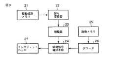
図3に示すように、駆動信号発生器は、駆動波形メモリ21、D/A変換器22、増幅器23、駆動信号選択手段24、画像メモリ25、デコーダ26で構成されている。駆動波形メモリ21は、後述するインクを吐出させる圧力室9に印加する駆動信号ACT1〜ACT5の波形情報と、インクを吐出させない圧力室9に印加する駆動信号INAの波形情報を記憶している。D/A変換器22は、駆動信号ACT1〜ACT5、INAの波形情報を受け取り、その波形情報をアナログ信号に変換する。増幅器23はこのアナログ信号に変換された駆動信号ACT1〜ACT5、INAを増幅し、駆動信号選択手段24に供給している。駆動信号の選択は、画像メモリ25に記憶した画像の各画素の階調情報を基に、デコーダ26を通して行っている。デコーダ26は画像メモリ25に記録された各画素の階調情報からインク滴の吐出/非吐出を制御するON/OFF信号を発生し、駆動信号選択手段24に供給している。そのON/OFF信号にしたがって駆動信号選択手段24は駆動信号ACT1〜ACT5、INAの中から駆動信号を選択しインクジェットヘッドへ印加する。A drive signal generator for driving the inkjet head with a drive signal will be described.
As shown in FIG. 3, the drive signal generator includes a
ここでは、1画素につき最大で8値の階調記録を行う。すなわち、吐出体積が6plの第1ドロップ、吐出体積が12plの第2ドロップ、吐出体積が24plの第3ドロップの3滴のインク滴の吐出/非吐出を表1に示すように制御することにより8値の階調記録を行う。
駆動信号選択手段24について詳述する。図4に示すように、駆動信号選択手段24はアナログスイッチ28a〜28jを備え、デコーダ26からのON/OFF信号29a〜29jによりアナログスイッチ28a〜28jをそれぞれオン、オフ動作する。なお、図4は、図2に示した一部のヘッドの電極に対応したアナログスイッチ28a〜28jについて示しているが、実際にはインクジェットヘッド27の全ての圧力室9の電極12に対応してアナログスイッチは設けられる。 The drive signal selection means 24 will be described in detail. As shown in FIG. 4, the drive signal selection means 24 includes
アナログスイッチ28a〜28eはON/OFF信号29a〜29eがオンのとき、増幅器23から入力した駆動信号ACT1〜ACT5をそれぞれ選択してインクジェットヘッド27の電極12a〜12eにそれぞれ供給し、ON/OFF信号29a〜29eがオフのときには増幅器23から入力した駆動信号INAを選択してインクジェットヘッド27の電極12a〜12eにそれぞれ供給する。 When the ON / OFF signals 29a to 29e are ON, the analog switches 28a to 28e select the drive signals ACT1 to ACT5 input from the
アナログスイッチ28f〜28jはON/OFF信号29f〜29jがオンのとき、増幅器23から入力した駆動信号ACT1〜ACT5をそれぞれ選択してインクジェットヘッド27の電極12f〜12jにそれぞれ供給し、ON/OFF信号29f〜29jがオフのときには増幅器23から入力した駆動信号INAをそれぞれ選択してインクジェットヘッド27の電極12f〜12jにそれぞれ供給する。 When the ON / OFF signals 29f to 29j are ON, the analog switches 28f to 28j select the drive signals ACT1 to ACT5 input from the
駆動信号ACT1〜ACT5は5分割駆動の第1〜第5サイクルにそれぞれ対応している。例えば、あるタイミングにおいて、圧力室9cからインク滴を吐出させ、同じ動作タイミングにある5つ離れた圧力室9hからはインクを吐出させない場合、圧力室9cに対応するON/OFF信号29cと、その左右のON/OFF信号29a、29b、29d、29eをONとし、圧力室9hに対応するON/OFF信号29hと、その左右のON/OFF信号29f、29g、29i、29jをOFFとする。これらのON/OFF信号29a〜29jにより、インク滴を吐出させる圧力室9cとその左右の圧力室9a、9b、9d、9eにはACT3、ACT1、ACT2、ACT4、ACT5の各駆動信号を供給し、インクを吐出させない圧力室9hとその左右の圧力室9f、9g、9i、9jにはINAの駆動信号を供給する。 The drive signals ACT1 to ACT5 correspond to the first to fifth cycles of the 5-division drive, respectively. For example, when ink droplets are ejected from the
駆動信号選択手段24に供給されるインク吐出用の駆動信号ACT1〜ACT5及びインク非吐出用の駆動信号INAについて述べる。
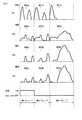
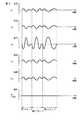
図5に、駆動信号ACT1〜ACT5と、駆動信号INAの1印字周期分、すなわち、5サイクル分を示す。駆動信号ACT1〜ACT5は、W1,W2,W3の3つの駆動信号で構成され、駆動信号INAは駆動信号W4で構成される。駆動信号W1はインク滴を吐出する圧力室9の電極12に印加される駆動信号である。The ink ejection drive signals ACT1 to ACT5 and the ink non-ejection drive signal INA supplied to the drive
FIG. 5 shows the drive signals ACT1 to ACT5 and one print cycle of the drive signal INA, that is, five cycles. The drive signals ACT1 to ACT5 are composed of three drive signals W1, W2, and W3, and the drive signal INA is composed of the drive signal W4. The drive signal W1 is a drive signal applied to the
駆動信号ACT1〜ACT5は、それぞれ時分割された時間だけ位相が異なる。例えば、図2における圧力室9cからインク滴を吐出させる場合は第3サイクルであり、この第3サイクルにおいてON/OFF信号29a〜29eをONにすることにより、圧力室9aと圧力室9eの電極12aと12eには駆動信号W3が印加され、圧力室9bと圧力室9dの電極12bと12dには駆動信号W2が印加され、圧力室9cの電極12cには駆動信号W1が印加される。 The phases of the drive signals ACT1 to ACT5 are different from each other by time division. For example, the case where ink droplets are ejected from the
駆動信号W1〜W4について述べる。図6に示すように、駆動信号W1〜W4は、それぞれ体積が6plの第1ドロップを吐出させる期間にある駆動信号W1a、W2a、W3a、W4aと、体積が12plの第2ドロップを吐出させる期間にある駆動信号W1b、W2b、W3b、W4bと、体積が24plの第3ドロップを吐出させる期間にある駆動信号W1c、W2c、W3c、W4cとで構成されている。 The drive signals W1 to W4 will be described. As shown in FIG. 6, the drive signals W1 to W4 are the drive signals W1a, W2a, W3a, and W4a in the period for discharging the first drop having a volume of 6 pl, and the period for discharging the second drop having a volume of 12 pl. Drive signals W1b, W2b, W3b, and W4b, and drive signals W1c, W2c, W3c, and W4c that are in a period for discharging a third drop having a volume of 24 pl.
例えば、図2における圧力室9cから第1ドロップを吐出させ、圧力室9hからは第1ドロップを吐出させない場合、図5に示す第3サイクルの第1ドロップの期間にON/OFF信号29a〜29eをONにし、ON/OFF信号29f〜29jをOFFにする。その結果、電極12cにはW1aの駆動信号が印加され、電極12b、12dにはW2aの駆動信号が印加され、電極12a、12eにはW3aの駆動信号が印加され、電極12f〜12jにはW4aの駆動信号が印加される。 For example, when the first drop is discharged from the
この結果、アクチュエータ14c、14dは駆動信号W1aとW2aの電圧差により大きく変形して、圧力室9cから6plのインク滴が吐出する。アクチュエータ14bと14eは、駆動信号W2aとW3aの電圧差により圧力室9b、9dに発生する圧力振動を圧力室9a、9eに分散させる方向に変形する。また、アクチュエータ14fには、駆動信号W3aとW4aの電位差により、圧力室9eに発生する圧力によりアクチュエータ14fが変形しようとするに抗する力が発生し、アクチュエータ14fが実質的に変形しなくなる。 As a result, the
そのため、圧力室9cで吐出動作を行った際に圧力室9eに発生する圧力振動がアクチュエータ14fを介して圧力室9fに漏洩する現象が遮断され、実質的にアクチュエータを介するクロストークを無視できる程度にすることができる。アクチュエータ14g〜14jには、各アクチュエータを挟む電極12f,12g,12h,12i,12jに同じ駆動信号W4aが印加されるため、電界が生じない。そのため、アクチュエータ14g〜14jは変形せず、圧力室9f〜9jには圧力振動が生じない。従って、圧力室9hからはインクは吐出されない。 For this reason, the phenomenon that the pressure vibration generated in the
駆動信号W1〜W4の決定方法について述べる。駆動信号W1〜W4は、残留圧力振動の抑制、クロストークの防止、階調制御,アクチュエータの固有振動の抑制などの観点から望ましいメニスカス振動を定義しておき、このような振動をメニスカスに生じさせる駆動信号を、インクジェットヘッドの駆動信号に対するメニスカスの流速振動の応答特性を利用して逆算することによって求める。以下、駆動信号を逆算するために定義されたメニスカス振動を仮想メニスカス振動と称する。メニスカスの流速を単に流速と称する。 A method for determining the drive signals W1 to W4 will be described. The drive signals W1 to W4 define desirable meniscus vibrations from the viewpoints of suppressing residual pressure vibration, prevention of crosstalk, gradation control, suppression of natural vibration of the actuator, and the like, and causing such vibrations to occur in the meniscus. The drive signal is obtained by back-calculating using the response characteristic of the meniscus flow velocity vibration to the drive signal of the inkjet head. Hereinafter, the meniscus vibration defined to calculate the drive signal backward is referred to as virtual meniscus vibration. The flow rate of the meniscus is simply called the flow rate.
仮想メニスカス振動は駆動信号に対して線形なメニスカス振動であり、実際のインクジェットヘッドの吐出動作において生じるメニスカス振動から、ノズルからのインク吐出に伴うメニスカスの前進や、ノズルからインクが排出された後に発生するメニスカスの後退や、インクの表面張力等によるインクのリフィル作用に伴うメニスカスの前進などの非線形な成分を除去した仮想の振動である。 Virtual meniscus vibration is linear meniscus vibration with respect to the drive signal, and occurs after meniscus vibration that occurs in the actual ink jet head ejection operation, as meniscus advances due to ink ejection from the nozzle, and after ink is discharged from the nozzle This is a virtual vibration in which non-linear components such as the meniscus retreat and the meniscus advance due to the ink refill action due to the surface tension of the ink are removed.
メニスカス振動の線形成分である仮想メニスカス振動は、インクが吐出しない程度に振幅を縮小した駆動信号をインクジェットヘッドに与えた場合に発生するメニスカス振動の振幅を拡大したものと考えることができる。図7に実際のメニスカス振動と仮想メニスカス振動の相違を示す。図中実線は仮想メニスカス振動を示し、図中点線は実際のメニスカス振動を示している。 The virtual meniscus vibration, which is a linear component of the meniscus vibration, can be considered as an expansion of the amplitude of the meniscus vibration that occurs when a drive signal whose amplitude is reduced to the extent that ink is not ejected is applied to the inkjet head. FIG. 7 shows the difference between actual meniscus vibration and virtual meniscus vibration. The solid line in the figure indicates the virtual meniscus vibration, and the dotted line in the figure indicates the actual meniscus vibration.
図7に示されるように、仮想メニスカス振動はインクジェットヘッドから実際にインクを吐出させたときに生じるメニスカス振動とは異なるが、インクの吐出速度や吐出体積、インク吐出動作後の残留振動、ノズル間のクロストーク、アクチュエータの固有振動によるメニスカスの微振動など、インクジェットヘッドの吐出動作に重要な特性を反映している。また、実際のメニスカス振動は前述の非線形振動成分の影響すなわち駆動信号によるメニスカス振動とは無関係な要因の影響を受けるので、実際のメニスカス振動を駆動信号により制御することには限界がある。これに対し、仮想メニスカス振動は駆動信号によるメニスカス振動とは無関係な要因の影響を受けないので、駆動信号により制御することが十分可能である。従って、望ましい仮想メニスカス振動を定義し、それを生じさせる駆動信号をアクチュエータに与えることにより、インクの吐出速度や吐出体積、インク吐出動作後の残留振動、ノズル間のクロストーク、アクチュエータの固有振動によるメニスカスの微振動などに関して望ましい特性を得ることができる。 As shown in FIG. 7, the virtual meniscus vibration is different from the meniscus vibration that occurs when ink is actually ejected from the inkjet head. However, the ink ejection speed and ejection volume, residual vibration after the ink ejection operation, This reflects important characteristics for the ejection operation of the inkjet head, such as crosstalk of the ink jet and fine vibration of the meniscus due to the natural vibration of the actuator. In addition, since actual meniscus vibration is affected by the influence of the above-described nonlinear vibration component, that is, by a factor unrelated to the meniscus vibration by the drive signal, there is a limit to controlling the actual meniscus vibration by the drive signal. On the other hand, the virtual meniscus vibration is not affected by factors unrelated to the meniscus vibration caused by the drive signal, and can be sufficiently controlled by the drive signal. Therefore, by defining the desired virtual meniscus vibration and giving the actuator a drive signal that generates it, the ink ejection speed and volume, residual vibration after the ink ejection operation, crosstalk between nozzles, and the inherent vibration of the actuator Desirable characteristics can be obtained with respect to fine vibration of the meniscus.
仮想メニスカス振動から駆動信号を逆算する過程について述べる。初めに、仮想メニスカス振動から駆動信号を逆算する過程で必要となる、インクジェットヘッドの駆動信号に対する流速振動の応答特性Rを求める。次に、求めた応答特性Rを基に仮想メニスカス振動から駆動信号を算出している。 The process of calculating the drive signal from the virtual meniscus vibration will be described. First, the response characteristic R of the flow velocity vibration with respect to the drive signal of the inkjet head, which is required in the process of calculating the drive signal from the virtual meniscus vibration, is obtained. Next, a drive signal is calculated from virtual meniscus vibration based on the obtained response characteristic R.
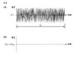
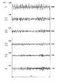
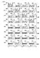
応答特性Rは、テスト駆動信号VTに対するノズル内の流速振動UTから求める。具体的には、テスト駆動信号VT1〜VT10を各々の電極12a〜12jに印加する。駆動信号VT1は、図8に示すようなインクが吐出しない程度の低電圧の周期Tcのノイズ波形であり、駆動信号VT2〜VT10は0Vとする。周期Tcは、インク吐出動作の時間より十分長くすることが望ましい。さらに、電極12kに対しては電極12aと同じ駆動信号VT1を印加することで、多数の圧力室に対して10チャンネルおきの駆動パターンを適用する。そのような駆動パターンでヘッドを駆動するときのノズル10a〜10j内のメニスカスの流速を各々UT1〜UT10としたとき、図9に示すような周期Tcの流速振動が発生する。ここでいうチャンネルとは1つのノズルに繋がる圧力室、電極を示し、仮想メニスカス振動の算出を説明するために用いている。この流速振動は、市販のレーザードップラー振動計、例えば(株)小野測器のLV−1710を用い、インクジェットヘッドのノズル内のメニスカスに測定用レーザビームを照射することによって観測することができる。
続いて、下記の(1)式と(2)式を用いて、テスト駆動信号VTと、流速振動UTをフーリエ変換し、それぞれ電圧スペクトルFVTと流速スペクトルFUTに変換する。
Subsequently, using the following equations (1) and (2), the test drive signal VT and the flow velocity vibration UT are Fourier transformed to be converted into a voltage spectrum FVT and a flow velocity spectrum FUT, respectively.
ここで、mは、レーザードップラー振動計で観測された時系列流速データのデータ数である。レーザードップラー振動計で観測された流速データのサンプリング時間をdtとすれば、mはTc/dtの値となる。添字のiは、チャンネル番号を示す1から10までの整数であり、この番号は電極12a〜12j、又は、ノズル10a〜10jに対応している。また、添字のjは、時系列データにおいて先頭からj番目のデータを示す1〜mまでの整数である。j番目のデータは、時刻j×dtのデータを示している。添字のkは、周波数系列データにおいて先頭からk番目のデータを示す1〜mまでの整数である。k番目のデータは、周波数(k−1)/Tcのデータを示している。Iは虚数単位である。ここで述べた添字の記法は以下の説明においても用いることとする。VTi、UTiは時間間隔dtで長さmの時系列データであり、また、FVTi、FUTiは、周波数間隔1/(m dt)おきの周波数系列データである。Here, m is the number of time-series flow velocity data observed with a laser Doppler vibrometer. If the sampling time of flow velocity data observed with a laser Doppler vibrometer is dt, m is a value of Tc / dt. The subscript i is an integer from 1 to 10 indicating the channel number, and this number corresponds to the
電圧スペクトルFVTi,kは、駆動信号VTiの周波数(k−1)/Tcにおける電圧振幅と位相を複素数の形で表している。また、流速スペクトルFUTi,kは、流速振動UTiの周波数(k−1)/Tcにおける流速振幅と位相を複素数の形で表している。
次に電圧スペクトルFVTと流速スペクトルFUTから、下記(3)式により応答特性R
を求める。The voltage spectrum FVTi, k represents the voltage amplitude and phase at the frequency (k−1) / Tc of the drive signal VTi in complex form. The flow velocity spectrum FUTi, k represents the flow velocity amplitude and phase at the frequency (k−1) / Tc of the flow velocity vibration UTi in the form of complex numbers.
Next, from the voltage spectrum FVT and flow velocity spectrum FUT, the response characteristic R
Ask for.
Ri,k=FUTi,k/FVT1,k …(3)
Ri,kは、駆動信号VT1に対するノズル内のメニスカス流速UTiの周波数(k−1)/Tcにおける振幅と位相の変化を複素数の形で示している。Riを各チャンネルの応答特性とするとき、R1〜R10の絶対値を図10に示し、位相角を図11に示す。図10のfmaxは、ノズル10内のメニスカスが、駆動信号に対して低周波領域から連続して応答可能な周波数領域の上限の周波数である。Ri, k = FUTi, k / FVT1, k (3)
Ri, k indicates changes in amplitude and phase in the frequency (k−1) / Tc of the meniscus flow velocity UTi in the nozzle with respect to the drive signal VT1 in the form of complex numbers. When the Ri and response characteristics of eachchannel, the absolute value of the R 1to R 10 in FIG. 10 shows the phase angle in FIG. Fmax in FIG. 10 is an upper limit frequency in the frequency region in which the meniscus in the
ここでは、テスト駆動信号VTとしてノイズ波形を用いた場合について説明したが、テスト駆動信号として周波数可変の正弦波や余弦波を用い、各周波数におけるメニスカス流速振動の振幅と位相を測定することによって応答特性Rを求めることも可能である。 Although a case where a noise waveform is used as the test drive signal VT has been described here, a response is obtained by measuring the amplitude and phase of the meniscus flow velocity vibration at each frequency using a variable frequency sine wave or cosine wave as the test drive signal. It is also possible to obtain the characteristic R.
次に、上記方法で求めた応答特性Rを用い、仮想メニスカス振動から駆動信号を決定する方法について述べる。
図12は仮想メニスカス振動の変位Xを示す図である。例えば、圧力室9cから第1〜第3ドロップを吐出させ、圧力室9hからはインクを吐出させない場合、ノズル10a〜10jの仮想メニスカス振動の変位はそれぞれX1〜X10となる。圧力室の仮想メニスカス変位のプラス側の山のピークが各ドロップのインクの吐出体積に相当する。Next, a method for determining a drive signal from virtual meniscus vibration using the response characteristic R obtained by the above method will be described.
FIG. 12 is a diagram showing the displacement X of the virtual meniscus vibration. For example, by discharging the first to third drop from the
仮想メニスカス変位Xiに対応する仮想メニスカス流速Uiを求める。仮想メニスカス流速Uiは、下記(4)式により求められる。A virtual meniscus flow velocity Ui corresponding to the virtual meniscus displacement Xi is obtained. The virtual meniscus flow velocity Ui is obtained by the following equation (4).
Ui=d/dt・Xi …(4)
図13に、上記(4)式により求めた仮想メニスカス流速U1〜U10を示す。
次に、下記(5)を用いて仮想メニスカス流速Uのフーリエ変換を行い、仮想メニスカス流速Uの流速スペクトルFUを得る。
FIG. 13 shows virtual meniscus flow velocities U1 to U10 obtained by the above equation (4).
Next, Fourier transform of the virtual meniscus flow velocity U is performed using the following (5) to obtain a flow velocity spectrum FU of the virtual meniscus flow velocity U.
ここで、Uiは時間間隔dtで長さmの時系列データであり、Ui,jは、Uiの先頭からj番目のデータである。また、流速スペクトルFUi,kは、仮想メニスカス流速Ui周波数(k−1)/Tcにおける流速振幅と位相を複素数の形で表している。このようにして得られた流速スペクトルFUのうち、FU3の絶対値を図14に示す。この流速スペクトルFUの周波数の大部分は、図14に示すように前述した周波数fmaxより低い周波数に含まれることが望ましい。Here, Ui is time-series data having a length m at a time interval dt, and Ui, j is j-th data from the top of Ui . The flow velocity spectrum FUi, k represents the flow velocity amplitude and phase at the virtual meniscus flow velocity Ui frequency (k−1) / Tc in the form of complex numbers. Of the flow velocity spectrum FU thus obtained, the absolute value of FU3 is shown in FIG. As shown in FIG. 14, most of the frequency of the flow velocity spectrum FU is preferably included in a frequency lower than the above-described frequency fmax.
次に、インクジェットヘッドの応答特性Rと仮想メニスカス振動の流速スペクトルFUとから、駆動信号の電圧スペクトルFVAを求める。応答特性行列[R]kを下記(6)式、電圧ベクトル{FVA}kを下記(7)式、仮想メニスカス振動の流速ベクトル{FU}kを下記(8)式としたとき、下記(9)式により周波数(k−1)/Tcにおける電圧ベクトルFVAkが求められる。
(7)式および(9)式で得られた電圧スペクトルFVAi,kは、仮想メニスカス流速Uiを発生させる駆動信号VAiの、周波数(k−1)/Tcにおける電圧振幅と位相を複素数の形で表している。また、(6)式で得られる[R]kのa行b列目の要素は、b番目のチャンネルの周波数(k−1)/Tcの電圧振動に対するa番目のチャンネルに設けられたノズル内のメニスカス流速振動の振幅と位相の変化を複素数の形で表している。[R]k−1は[R]kの逆行列である。逆行列の演算は、WOLFRAM RESEARCH社のMATHEMATICAなどの数式解析ソフトウエアにより行うことができる。The voltage spectrum FVAi, k obtained by the equations(7) and (9) is a complex number representing the voltage amplitude and phase at the frequency (k−1) / Tc of the drive signal VAi for generating the virtual meniscus flow velocity Ui. It is expressed in the form of In addition, the element in the a row and the b column of [R]k obtained by the equation (6) is the inside of the nozzle provided in the a-th channel with respect to the voltage oscillation of the frequency (k-1) / Tc of the b-th channel. The change in the amplitude and phase of the meniscus flow velocity oscillation is expressed in complex form. [R]k−1 is an inverse matrix of [R]k . The inverse matrix can be calculated by mathematical analysis software such as MATHEMATICA of WOLFRAM RESEARCH.
次に、駆動信号VAiを求める。駆動信号VAiは、電圧スペクトルFVAiを、下記(10)式により逆フーリエ変換することにより求めることができる。
ここで、Re[z]は、複素数z=a+bIの実数部aを得る関数である。VAi,jは、仮想メニスカス流速Uを発生させる駆動信号VAの、i番目のチャンネルの時刻j×dtにおける電圧値である。Here, Re [z] is a function for obtaining the real part a of the complex number z = a + bI. VAi, j is a voltage value at the time j × dt of the i-th channel of the drive signal VA for generating the virtual meniscus flow velocity U.
得られた駆動信号VAiを図1に示すヘッドに印加する。すなわちVA1〜VA10をそれぞれ電極12a〜12jに印加すると、ノズル10a〜10j内のメニスカスに仮想メニスカス変位X1〜X10を生じさせることになる。The obtained drive signal VAi is applied to the head shown in FIG. That is, when VA1 to VA10 are respectively applied to the
また、m′は、
m′≦fmax・Tc
となる最も大きい整数である。このように逆フーリエ変換の周波数の上限をfmaxとすることにより、駆動信号VAの周波数成分の上限値がfmaxに定められる。M ′ is
m ′ ≦ fmax · Tc
Is the largest integer. Thus, by setting the upper limit of the frequency of the inverse Fourier transform to fmax, the upper limit value of the frequency component of the drive signal VA is set to fmax.
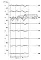
駆動信号の波形を仮想メニスカス振動からフーリエ変換を用いて逆算する場合、演算を行う周波数の範囲をインクジェットヘッドが応答する周波数の範囲である0〜fmaxに制限することにより、計算結果が発散することを防止できる。計算の結果得られた波形の駆動信号が十分な精度で仮想メニスカス振動を再現するためには、fmaxが流速スペクトルFUの周波数成分の大部分を含んでいることが望ましい。駆動信号VAの電圧変動が現れる期間や電圧振幅は、圧力室の長さLなどのインクジェットヘッドの寸法によって変化する。圧力室の長さLは、電圧変動が現れる期間が所定の範囲内で、電圧振幅が最も小さくなる値に定められることが望ましい。以上のようにして得られた駆動信号VA(VA1〜VA10)を図15に示す。When the waveform of the drive signal is calculated backward from the virtual meniscus vibration using Fourier transform, the calculation result is diverged by limiting the frequency range for the calculation to 0 to fmax, which is the frequency range to which the inkjet head responds. Can be prevented. In order for the drive signal having the waveform obtained as a result of the calculation to reproduce the virtual meniscus vibration with sufficient accuracy, it is desirable that fmax includes most of the frequency components of the flow velocity spectrum FU. The period in which the voltage variation of the drive signal VA appears and the voltage amplitude vary depending on the dimensions of the inkjet head, such as the length L of the pressure chamber. The length L of the pressure chamber is preferably set to a value that minimizes the voltage amplitude within a predetermined range in which the voltage fluctuation appears. FIG. 15 shows drive signals VA (VA1 to VA10 ) obtained as described above.
以上のようにして得られた駆動信号VAは、そのままインクジェットヘッドの駆動信号として用いることが可能である。駆動信号VAをそのまま駆動信号として用いる代わりに、駆動信号VAから図15に点線で示すような基準電圧波形VREF(VREF1〜VREF10)との差を計算して、図16に示す駆動信号VB(VB1〜VB10)を得ることにより、第1ドロップから第3ドロップまでの駆動信号の長さを短縮できる。このことにより、インクジェットヘッドの駆動周期を短縮でき、印刷速度を向上させることができる。The drive signal VA obtained as described above can be directly used as a drive signal for the inkjet head. Instead of using the drive signal VA as a drive signal as it is, a difference between the drive signal VA and a reference voltage waveform VREF (VREF1 to VREF10 ) as shown by a dotted line in FIG. 15 is calculated, and the drive signal VB shown in FIG. By obtaining (VB1 to VB10 ), the length of the drive signal from the first drop to the third drop can be shortened. As a result, the drive cycle of the inkjet head can be shortened, and the printing speed can be improved.
得られた駆動信号VBは、そのままインクジェットヘッドの駆動信号として用いることが可能である。さらに下記(11)式で算出した駆動信号VDを用いることにより、駆動信号の電圧振幅を小さくできる。電圧振幅を減らすことで、駆動回路のコストを低減でき、安価なインクジェット記録装置を提供できる。図17に、駆動信号VD1〜VD10を示す。The obtained drive signal VB can be directly used as a drive signal for the inkjet head. Furthermore, the voltage amplitude of the drive signal can be reduced by using the drive signal VD calculated by the following equation (11). By reducing the voltage amplitude, the cost of the drive circuit can be reduced, and an inexpensive ink jet recording apparatus can be provided. FIG. 17 shows drive signals VD1 to VD10 .
VDi,j=VBi,j−MIN[VB1,j,VB2,j,…VB10,j] …(11)
ここで、MIN[VB1,j,VB2,j,…]は、[ ]内の値のうち最小の値を示す関数である。この計算で求めた駆動信号VD3は駆動信号W1になり、駆動信号VD2またはVD4は駆動信号W2になり、駆動信号VD1またはVD5は駆動信号W3になり、駆動信号VD6〜VD10のいずれかは駆動信号W4になる。こうして、インクを吐出する圧力室9cを駆動するアクチュエータ14c、14dに印加される駆動信号VEは、VD3−VD2で算出され、図18に示す駆動信号となる。VDi, j = VBi, j −MIN [VB1, j , VB2, j ,... VB10, j ] (11)
Here, MIN [VB1, j , VB2, j ,...] Is a function indicating the minimum value among the values in []. The calculation by the drive signal VD3 obtained becomes drive signal W1, drive signal VD2 or VD4 becomes drive signal W2, drive signal VD1 or VD5 becomes drive signal W3, drive
以上述べた駆動信号の作成方法をインクジェット記録装置の製造に応用するには、以下の手順で行う。まず、ノイズ波形あるいは正弦波などのテスト駆動信号を用い、製造されたインクジェットヘッドの電圧信号に対するメニスカスの応答特性Rを測定する。次に、応答特性Rと、あらかじめ定められた仮想メニスカス振動をもとに、(4)式〜(10)式により駆動信号の波形を演算により作成する。次に、必要に応じて(11)式などにより駆動信号の波形を変形する。最後に、得られた駆動信号の波形をインクジェット記録装置の駆動波形メモリ21に記憶させる。 To apply the drive signal generation method described above to the manufacture of an ink jet recording apparatus, the following procedure is used. First, using a test drive signal such as a noise waveform or a sine wave, the response characteristic R of the meniscus to the voltage signal of the manufactured inkjet head is measured. Next, based on the response characteristic R and a predetermined virtual meniscus vibration, the waveform of the drive signal is created by calculation using equations (4) to (10). Next, if necessary, the waveform of the drive signal is deformed by the equation (11) or the like. Finally, the waveform of the obtained drive signal is stored in the
仮想メニスカス振動について、図12及び図13を用いて詳細に述べる。
1画素を形成するために吐出体積が異なる複数のインクドロップを選択的に吐出させる場合、各ドロップの吐出速度が各々大きく異なると、インク滴の着弾位置精度が低下したり、インク吐出動作が不安定になる。各ドロップの吐出速度を適当な範囲内に収めることが困難になり、吐出速度が低すぎることによる着弾位置精度の悪化や吐出速度が大きすぎることによる動作安定性の悪化を招く。吐出速度は、インクの吐出時間をst、インク吐出時のメニスカス変位をaとするとき、おおむねa/stの値によって定まる。The virtual meniscus vibration will be described in detail with reference to FIGS.
When a plurality of ink drops having different ejection volumes are selectively ejected in order to form one pixel, if the ejection speed of each drop is greatly different, the ink droplet landing position accuracy is reduced or the ink ejection operation is not performed. Become stable. It becomes difficult to keep the discharge speed of each drop within an appropriate range, and the landing position accuracy is deteriorated due to the discharge speed being too low, and the operation stability is deteriorated due to the discharge speed being too high. The ejection speed is generally determined by the value of a / st, where st is the ink ejection time and a is the meniscus displacement during ink ejection.
この実施例は、図12で示すように、インクを吐出させるノズル10cの仮想メニスカス振動の変位X3を例示している。第1ドロップ、第2ドロップ、第3ドロップの吐出時の吐出時間をそれぞれst1、st2、st3とし、インク吐出時の仮想メニスカス変位の動きをa1、a2、a3とするとき、
a1/st1≒a2/st2≒a3/st3
としている。吐出時間と仮想メニスカスの変位量の比を一定にするように仮想メニスカス振動を定めることにより、異なる吐出体積のインクドロップを略一定の速度で吐出できる。This embodiment, as shown in Figure 12 illustrates the displacement X3 of hypothetical meniscus vibration in nozzle 10c to eject ink. When the discharge times at the time of discharging the first drop, the second drop, and the third drop are st1, st2, and st3, respectively, and the movement of the virtual meniscus displacement at the time of ink discharge is a1, a2, and a3,
a1 / st1≈a2 / st2≈a3 / st3
It is said. By defining the virtual meniscus vibration so that the ratio of the discharge time and the displacement amount of the virtual meniscus is constant, ink drops having different discharge volumes can be discharged at a substantially constant speed.
また、各ドロップの仮想メニスカス変位の終端に、変位が0で、かつ変位の時間微分、すなわち流速が0となるタイミングを設けることにより、各ドロップの吐出動作終了後の残留振動を実質的に0にしている。このことにより、例えば、第2ドロップを吐出させる場合、第1ドロップを吐出させたか否かによる吐出速度の変動を防止でき、各ドロップの吐出速度を均一化できる。 Further, by providing a timing at which the displacement is zero and the time differentiation of the displacement, that is, the flow velocity becomes zero, at the end of the virtual meniscus displacement of each drop, the residual vibration after the discharge operation of each drop is substantially zero. I have to. Thereby, for example, when the second drop is ejected, it is possible to prevent variation in the ejection speed depending on whether or not the first drop is ejected, and the ejection speed of each drop can be made uniform.
また、図13において、インクを吐出させないノズル10a,10b,10d,10eの流速振動U1,U2,U4,U5は、インクを吐出させるノズル10cの流速振動U3の−1/4になっている。すなわち、図13に示す仮想メニスカス流速は、インク吐出ノズル10cのインク吐出に伴う隣接ノズル10b,10dの流速振動を、隣接ノズルを含むインク非吐出ノズル10a,10b,10d,10eに対して均一に分散させる。このように仮想メニスカス流速を定めて駆動波形を演算することにより,実際のメニスカスにおいても非吐出ノズルに対してインク吐出動作に伴う流速振動を均一に分散させることができる.流速振動の振幅と圧力振動の振幅が比例することから、図13に示す仮想メニスカス流速は、インクを吐出させる圧力室9cのインク吐出動作に伴う、隣接圧力室9b,9dの圧力振動を、インクを吐出させない圧力室に対して均一に分散させるとも言える。さらに、このような圧力振動は、圧力室の容積の変化により発生することから、図13に示す仮想メニスカス流速は、インクを吐出させない圧力室9a,9b,9d,9eの容積を均一に可変させるとも言える。すなわち、図13に示す仮想メニスカス流速を用いて駆動信号の波形を演算することにより、インクを吐出させない圧力室の容積を均一に可変させる駆動信号が得られる。In FIG. 13, the flow velocity vibrations U1 , U2 , U4 , and U5 of the nozzles 10 a, 10 b, 10 d, and 10 e that do not eject ink are −1/4 of the flow velocity vibration U3 of the nozzle 10 c that ejects ink. It has become. In other words, the virtual meniscus flow velocity shown in FIG. 13 causes the flow velocity vibration of the adjacent nozzles 10b and 10d accompanying the ink discharge of the ink discharge nozzle 10c to be uniform with respect to the ink non-discharge nozzles 10a, 10b, 10d and 10e including the adjacent nozzles. Disperse. In this way, by calculating the driving waveform while determining the virtual meniscus flow velocity, it is possible to uniformly disperse the flow velocity vibration associated with the ink ejection operation with respect to the non-ejection nozzles even in the actual meniscus. Since the amplitude of the flow velocity vibration is proportional to the amplitude of the pressure vibration, the virtual meniscus flow velocity shown in FIG. 13 represents the pressure vibration of the
非吐出ノズルにおいて、メニスカスの盛り上がりを生じさせる力は、おおむね各ノズルの流速振幅の2乗に比例する。そのため、非吐出ノズルに対してインク吐出動作に伴う流速振動を均一に分散させることで非吐出ノズル全体としてメニスカスの盛り上がりを生じさせる力を最小にすることができる。流速振動を均一に分散させることで、メニスカスがノズル面から盛り上がる現象を抑制することができ、インク吐出時に発生するメニスカスの位置のばらつきが小さくなり、インク滴の吐出速度のばらつきを抑制でき、印字品質を向上できる。 In the non-ejection nozzle, the force that causes the meniscus to rise is approximately proportional to the square of the flow velocity amplitude of each nozzle. Therefore, by uniformly distributing the flow velocity vibration accompanying the ink ejection operation to the non-ejection nozzles, it is possible to minimize the force that causes the meniscus to rise as a whole non-ejection nozzle. By uniformly distributing the flow velocity vibration, the phenomenon that the meniscus swells from the nozzle surface can be suppressed, the variation in meniscus position that occurs during ink ejection is reduced, the variation in ink droplet ejection speed can be suppressed, and printing Quality can be improved.
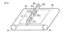
図19はインクジェットヘッドに対して上述した制御が行われるインクジェット記録装置の要部外観を示す斜視図である。このインクジェット記録装置は、例えば、4個のインクジェットヘッド271,272,273,274を、基板28を挟んで、千鳥状に配置して1つのラインヘッド29を構成している。FIG. 19 is a perspective view showing the external appearance of the main part of an inkjet recording apparatus in which the above-described control is performed on the inkjet head. The ink jet recording apparatus, for example, four ink-jet heads271, 272, 27 3, 274, across the
ラインヘッド29は媒体搬送ベルト30から所定の隙間だけ離れた位置に設置されている。媒体搬送ベルト30は搬送ローラ31によって矢印の方向に駆動するもので、用紙などの記録媒体32を上面に密着した状態で搬送する。記録媒体32がラインヘッド29の下を通過するとき、各インクジェットヘッド271〜274から下向きにインク滴を吐出し、このインク滴を記録媒体32に付着させて印刷を行う。なお、記録媒体32を媒体搬送ベルト30に密着させる方法としては、静電気や空気流により吸着させる方法や、記録用紙の端を部材で押さえる方法など、周知の方法を用いることができる。 The
ラインヘッド29の各インクジェットヘッド271〜274は圧力室のノズルから吐出するインク滴のタイミングをインクジェットヘッド間で調整することで、各インクジェットヘッド271〜274により記録媒体32に対して同一ラインを印刷できるようになっている。Each inkjet head27 1-274
この実施の形態では駆動回路として、インクを吐出させる圧力室9に印加する駆動信号ACT1〜ACT5の波形情報及びインクを吐出させない圧力室9に印加する駆動信号INAの波形情報を記憶した駆動波形メモリ21を設け、この駆動波形メモリ21から駆動信号を読み出し、それを駆動信号選択手段24にて選択するようにしたが必ずしもこれに限定するものではない。 In this embodiment, as a drive circuit, a drive waveform memory storing waveform information of the drive signals ACT1 to ACT5 applied to the
例えば、図20に示すように、仮想メニスカス振動情報を記憶した仮想メニスカス振動メモリ33と、応答特性R情報を記憶した応答特性メモリ34と、演算手段35を備えたインクジェット記録装置とすることも可能である。そのインクジェット記録装置内で、演算手段35にて、仮想メニスカス振動メモリ33の仮想メニスカス振動の変位から仮想メニスカス流速Uを求め、この仮想メニスカス流速Uから流速スペクトルFUを求め、この流速スペクトルFUと応答特性メモリ34に記憶した応答特性Rとから、駆動信号の電圧スペクトルFVAを求め、さらに(10)式および(11)式の演算を行って駆動信号をW1、W2、W3、W4を求めて駆動信号ACT1〜ACT5、INAを得るようにし、この駆動信号ACT1〜ACT5、INAを駆動信号選択手段24にて選択し、インク吐出制御をおこなうようにしてもよい。 For example, as shown in FIG. 20, an ink jet recording apparatus including a virtual meniscus vibration memory 33 that stores virtual meniscus vibration information, a response
この場合、演算手段35でfmax以上の電圧波形VAの周波数成分をカットするか、あらかじめ仮想メニスカス振動メモリ33に記憶される仮想メニスカス振動あるいは応答特性メモリ34に記憶される応答特性のfmax以上の周波数成分をカットしておくことが演算を簡単にするために望ましい。 In this case, the frequency component of the voltage waveform VA greater than or equal to fmax is cut by the computing means 35, or the virtual meniscus vibration stored in the virtual meniscus vibration memory 33 in advance or the frequency greater than or equal to fmax of the response characteristic stored in the response
この場合、演算手段35でfmax以上の電圧波形VAの周波数成分をカットするか、あらかじめ仮想メニスカス振動メモリ33に記憶される仮想メニスカス振動あるいは応答特性メモリ34に記憶される応答特性のfmax以上の周波数成分をカットしておくことが演算を簡単にするために望ましい。 In this case, the frequency component of the voltage waveform VA greater than or equal to fmax is cut by the computing means 35, or the virtual meniscus vibration stored in the virtual meniscus vibration memory 33 in advance or the frequency greater than or equal to fmax of the response characteristic stored in the response
(第2の実施の形態)
この実施の形態は、インクジェットヘッドを4分割駆動する場合について述べる。なお、前述した実施の形態と同一の部分には同一の符号を付し詳細な説明は省略する。(Second Embodiment)
In this embodiment, the case where the ink-jet head is driven in four parts will be described. Note that the same reference numerals are given to the same portions as those of the above-described embodiment, and detailed description thereof is omitted.
4分割駆動の場合は、圧力室9a〜9jにおいて、例えば、圧力室9c,9gが同じサイクルでインク吐出タイミングとなり、圧力室9cからも圧力室9gからもインクを吐出するときには図21の(a)に示すようにアクチュエータ14a〜14jが変形動作し、圧力室9cからはインクを吐出させるが圧力室9gからはインクを吐出させないときには図21の(b)に示すようにアクチュエータ14a〜14jが変形動作する。 In the case of the 4-split driving, in the
このような駆動制御を行う駆動信号選択手段の構成も5分割駆動のときとは異なり、図22の構成になる。すなわち、ON/OFF信号29a〜29jによりアナログスイッチ28a〜28jをそれぞれオン、オフ動作する。アナログスイッチ28a〜28dはON/OFF信号29a〜29dがオンのとき、入力した駆動信号ACT1〜ACT4をそれぞれ選択してインクジェットヘッド27の電極12a〜12dにそれぞれ供給し、ON/OFF信号29a〜29dがオフのときには入力した駆動信号INA1〜INA4をそれぞれ選択してインクジェットヘッド27の電極12a〜12dにそれぞれ供給する。 The structure of the drive signal selection means for performing such drive control is the structure shown in FIG. That is, the analog switches 28a to 28j are turned on and off by the ON / OFF signals 29a to 29j, respectively. When the ON / OFF signals 29a to 29d are ON, the analog switches 28a to 28d select the input drive signals ACT1 to ACT4 and supply them to the
アナログスイッチ28e〜28hはON/OFF信号29e〜29hがオンのとき、入力した駆動信号ACT1〜ACT4をそれぞれ選択してインクジェットヘッド27の電極12e〜12hにそれぞれ供給し、ON/OFF信号29e〜29hがオフのときには入力した駆動信号INA1〜INA4をそれぞれ選択してインクジェットヘッド27の電極12e〜12hにそれぞれ供給する。 When the ON / OFF signals 29e to 29h are ON, the analog switches 28e to 28h select the input drive signals ACT1 to ACT4 and supply them to the
アナログスイッチ28i,28j,…はON/OFF信号29i,29j,…がオンのとき、入力した駆動信号ACT1,ACT2,…をそれぞれ選択してインクジェットヘッド27の電極12i,12j,…にそれぞれ供給し、ON/OFF信号29i,29j,…がオフのときには入力した駆動信号INA1,INA2,…をそれぞれ選択してインクジェットヘッド27の電極12i,12j,…にそれぞれ供給する。 When the ON /
駆動信号ACT1〜4は、それぞれ4分割駆動における第1〜第4サイクルに対応している。例えば、図21の(b)に示すように、あるタイミングにおいて、圧力室9cからインクを吐出させ、同じ動作タイミングにある圧力室9gからはインクを吐出させない場合、圧力室9cに対応するON/OFF信号29cと、片側2つと、反対側1つの3つのON/OFF信号29a,29b,29dをONとし、圧力室9gに対応するON/OFF信号29gと、片側2つと、反対側1つの3つのON/OFF信号29e,29f,29hをOFFとすることにより、インクを吐出させる圧力室9cと片側2つと反対側1つの圧力室9a,9b,9dにはACT信号を供給し、インクを吐出させない圧力室9gと、片側2つと反対側1つの圧力室9e,9f,9hにはINA信号を供給する。 The drive signals ACT1 to ACT4 correspond to the first to fourth cycles in the 4-division drive, respectively. For example, as shown in FIG. 21B, when ink is ejected from the
駆動信号選択手段に供給される駆動信号ACT1〜ACT4及びINA1〜INA4について述べる。 The drive signals ACT1 to ACT4 and INA1 to INA4 supplied to the drive signal selection unit will be described.
図23に、インク吐出用の駆動信号ACT1〜ACT4と、インク非吐出用の駆動信号INA1〜INA4の1印字周期分を示す。駆動信号ACT1〜ACT4は、W1,W2,W3の3つの駆動信号から構成され、INA1〜INA4はW3,W4,W5の3つの駆動信号から構成されている。ACT1〜ACT4は、それぞれ時分割された時間だけ位相が異なる。例えば、圧力室9cからインクを吐出させる場合、第3サイクルにおいてON/OFF信号29a〜29dをONにすることにより、圧力室9aにはW3,圧力室9bと9dにはW2,圧力室9cにはW1の駆動信号が供給される。 FIG. 23 shows one print cycle of the ink discharge drive signals ACT1 to ACT4 and the ink non-discharge drive signals INA1 to INA4. The drive signals ACT1 to ACT4 are composed of three drive signals W1, W2 and W3, and INA1 to INA4 are composed of three drive signals W3, W4 and W5. The phases of ACT1 to ACT4 are different from each other by time division. For example, when ink is ejected from the
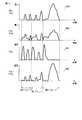
駆動信号W1〜W5について述べる。図24に示すように、駆動信号W1〜W5は、それぞれ体積が6plの第1ドロップを吐出させる期間にある駆動信号W1a、W2a、W3a、W4a、W5aと、体積が12plの第2ドロップを吐出させる期間にある駆動信号W1b、W2b、W3b、W4b、W5bと、体積が24plの第3ドロップを吐出させる期間にある駆動信号W1c、W2c、W3c、W4c、W5cとで構成されている。 The drive signals W1 to W5 will be described. As shown in FIG. 24, the drive signals W1 to W5 discharge the drive signal W1a, W2a, W3a, W4a, W5a and the second drop with a volume of 12 pl during the period of discharging the first drop with a volume of 6 pl, respectively. Drive signals W1b, W2b, W3b, W4b, W5b in the period to be discharged and drive signals W1c, W2c, W3c, W4c, W5c in the period to discharge the third drop having a volume of 24 pl.
例えば、圧力室9cから第1ドロップを吐出させ、圧力室9gからは第1ドロップを吐出させない場合、第3サイクルの第1ドロップの期間にON/OFF信号29a〜29dをONにし、ON/OFF信号29e〜29hをOFFにする。その結果、電極12cにはW1aの駆動信号が印加され、電極12b,12dにはW2aの駆動信号が印加され、電極12a,12eにはW3aの駆動信号が印加され、電極12f,12hにはW4aの駆動信号が印加され、電極12gにはW5aの駆動信号が印加される。 For example, when the first drop is discharged from the
この結果、図21の(b)に示すように、アクチュエータ14c,14dは駆動信号W1aとW2aの電圧差により大きく変形して圧力室9cから6plのインク滴が吐出する。アクチュエータ14b,14eは駆動信号W2aとW3aの電圧差により圧力室9b,9dに発生する圧力振動を圧力室9a,9eに分散させる方向に変形する。アクチュエータ14fは、駆動信号W3aとW4aの電位差により、圧力室9gから第1ドロップを吐出させる場合と同じように変形する。そのため、圧力室9cで吐出動作を行った際に圧力室9eに発生する圧力振動が、圧力室9gの吐出動作を行った場合と同じになり、実質的にクロストークを0にすることができる。 As a result, as shown in FIG. 21B, the
アクチュエータ14g,14hは、駆動信号W4aとW5aの電位差により、圧力室9gで発生する圧力振動を分散させるように変形する。このようにすることにより、圧力室9fから9hに発生する圧力振動は微小になり、非吐出ノズル10f〜10hにおけるメニスカスの盛り上がり現象などの印字品質に対する悪影響を低減できる。 The
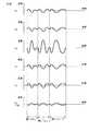
この実施の形態においても駆動信号の作成方法は前述した第1の実施の形態と同様である。すなわち、図25に仮想メニスカス変位Xを示すように、例えば、圧力室9cから第1〜第3ドロップを吐出させ、圧力室9gからはインクを吐出させない場合、ノズル10a〜10hの仮想メニスカス変位はそれぞれX1〜X8となる。また、この実施の形態におけるノズル10a〜10hの仮想メニスカス流速Uを図26に示し、駆動信号VAを図27に示し、駆動信号VBを図28に示し、駆動信号VDを図29に示す。Also in this embodiment, the method of generating the drive signal is the same as that in the first embodiment described above. That is, as shown in FIG. 25, for example, when the first to third drops are discharged from the
図26において非吐出ノズル10a,10b,10dの流速振動U1,U2,U4は、吐出ノズル10cの流速振動U3の−1/3になっている。このような構成において、図21の(a)に示すように、ノズル10c,10gからインクを同時に吐出させる場合には、非吐出ノズル10a,10b,10d,10e,10f,10hの流速振動U1,U2,U4,U5,U6,U8は、図30に示すように、吐出ノズル10c,10gの流速振動U3,U7に対して−1/3になる。すなわち、吐出ノズル10c,10gのインク吐出に伴う、隣接ノズル10b,10d,10f,10hの流速振動U2,U4,U6,U8を、非吐出ノズル10a,10b,10d,10e,10f,10hに対して均一に分散させることができる。このように仮想メニスカス流速を定めて駆動波形を演算することにより,実際のメニスカスにおいても非吐出ノズルに対してインク吐出動作に伴う流速振動を均一に分散させることができる。In FIG. 26, the flow velocity vibrations U1 , U2 , U4 of the non-discharge nozzles 10a, 10b, 10d are −1/3 of the flow velocity vibration U3 of the discharge nozzle 10c. In such a configuration, as shown in FIG. 21A, when ink is simultaneously ejected from the nozzles 10c and 10g, the flow velocity vibration U1 of the non-ejection nozzles 10a, 10b, 10d, 10e, 10f, and 10h. , U2 , U4 , U5 , U6 , U8 are −1/3 with respect to the flow velocity vibrations U3 , U7 of the discharge nozzles 10c, 10g, as shown in FIG. That is, the flow velocity vibrations U2 , U4 , U6 , U8 of the adjacent nozzles 10 b, 10 d, 10 f, 10 h that accompany ink discharge from the discharge nozzles 10 c, 10 g , 10 h can be uniformly dispersed. By calculating the virtual meniscus flow velocity and calculating the drive waveform in this way, even in an actual meniscus, the flow velocity vibration accompanying the ink ejection operation can be evenly distributed to the non-ejection nozzles.
流速振動の振幅と圧力振動の振幅が比例するので、インクを吐出させる圧力室9c,9gのインク吐出動作に伴う隣接圧力室9b,9d,9f,9hの圧力振動を、インクを吐出させない圧力室に対して均一に分散させることができることになる。さらに、このような圧力振動は、圧力室の容積の変化により発生することから、図30に示す仮想メニスカス流速振動は、インクを吐出させない圧力室9a,9b,9d,9e,9f,9hの容積を均一に可変できるとも言える。すなわち、図30に示す仮想メニスカス流速振動を用いて駆動信号の波形を演算することにより、インクを吐出させない圧力室の容積を均一に可変させる駆動信号を得ることができる。 Since the amplitude of the flow velocity vibration and the amplitude of the pressure vibration are proportional, the pressure chambers of the
非吐出ノズルにおいて、メニスカスの盛り上がりを生じさせる力は、各ノズルの流速の2乗に略比例する。そのため、非吐出ノズルに対してインク吐出動作に伴う流速振動を均一に分散させることで非吐出ノズル全体としてメニスカスの盛り上がりを生じさせる力を最小にすることができる。 In the non-ejection nozzle, the force that causes the meniscus to rise is approximately proportional to the square of the flow velocity of each nozzle. Therefore, by uniformly distributing the flow velocity vibration accompanying the ink ejection operation to the non-ejection nozzles, it is possible to minimize the force that causes the meniscus to rise as a whole non-ejection nozzle.
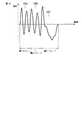
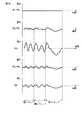
ここで、圧力室9cと9gから同時にインクを吐出させ、続いて、圧力室9dと9hから同時にインクを吐出させ、その後も、順次、圧力室9eと9i、圧力室9fと9jから同時にインクを吐出させた場合の、ノズル10c〜10fのメニスカス変位を数値解析シミュレーションした結果を図31に示す。図中実線は本実施の形態を示し、インクを吐出しない圧力室の容積を均一に可変させた場合を示している。また、点線は、従来に見られるように、インクを吐出しない圧力室の容積を不均一に可変させた場合を示している。不均一にさせた場合の容積変化の比は、1/4:1/4:1/2としている。また、図中矢印は、各ノズルにおいてインクの吐出が開始されるタイミングを示している。 Here, ink is ejected simultaneously from the
図31は、インクを吐出しない圧力室の容積を均一に可変させた場合(実線)と不均一に可変させた場合(点線)での、ノズル10c内のメニスカス変位を示している。この図から、1回目のインク吐出した後のメニスカスの盛り上がりは、実線で示している均一に可変させる形態の方が、点線で示すよりも抑制されていることがわかる。これによって、2回目の吐出動作により吐出するインク滴の速度の低下を抑制し、印字品質を改善できる効果が得られる。 FIG. 31 shows the meniscus displacement in the nozzle 10c when the volume of the pressure chamber that does not eject ink is uniformly varied (solid line) and when it is varied non-uniformly (dotted line). From this figure, it can be seen that the rise of the meniscus after the first ink discharge is suppressed in the uniformly variable form shown by the solid line rather than the dotted line. As a result, it is possible to suppress the decrease in the speed of the ink droplets ejected by the second ejection operation, and to obtain the effect of improving the print quality.
なお、前述した各実施の形態は、5分割駆動と4分割駆動について述べたがこれに限定するものではなく、6分割以上であってもよい。 In addition, although each embodiment mentioned above demonstrated 5 division drive and 4 division drive, it is not limited to this, Six division or more may be sufficient.
9,9a〜9k…圧力室、10…ノズル、12,12a〜12k…電極、14a〜14
k…アクチュエータ、21…駆動波形メモリ、24…駆動信号選択手段、27…インクジ
ェットヘッド。9, 9a-9k ... pressure chamber, 10 ... nozzle, 12, 12a-12k ... electrode, 14a-14
k ... Actuator, 21 ... Drive waveform memory, 24 ... Drive signal selection means, 27 ... Inkjet head.
Claims (4)
Translated fromJapanese前記圧力室を駆動する前記駆動信号を各々の圧力室の電極に供給する駆動信号発生手段を備え、
前記駆動信号発生手段は、連続するN(>=4)個の圧力室のうち1つからインクを吐出させると同時に、前記N個の圧力室のうち残りの圧力室の容積を実質的に均一に変形させる前記駆動信号を発生するもので、かつ、前記残りの圧力室のうち前記インクを吐出するノズルに連通する圧力室に隣接する圧力室に印加する駆動信号と、この圧力室に更に隣接する圧力室に印加する駆動信号とを異ならせるものであり、インクジェットヘッドの駆動信号に対するメニスカス流速振動の周波数応答特性を求めるとともに、駆動信号に対して線形な仮想メニスカス振動の変位に対応する仮想メニスカス流速として、インクを吐出するノズルに対応する仮想メニスカス流速と、複数のインクを吐出しないノズルに各々対応して実質的に均一の流速振幅を有する仮想メニスカス流速を求めて前記仮想メニスカス流速のフーリエ変換を行い、さらに、複数のノズルにおける仮想メニスカス流速のフーリエ変換結果の流速ベクトルを{FU}、インクジェットヘッドの駆動信号に対する各ノズル内のメニスカス流速振動の周波数応答特性の行列を[R]としたとき、電圧ベクトル{FVA}を、[R]−1・{FU}によって求め、さらに、この電圧ベクトル{FVA}を逆フーリエ変換することによって前記駆動信号を得ることを特徴とするインクジェット記録装置。A plurality of nozzles for discharging ink, a plurality of pressure chambers respectively communicating with the nozzles, an ink supply means for supplying ink to the pressure chambers, and a plurality of electrodes arranged corresponding to the pressure chambers; An inkjet head having an actuator that forms side walls that separate the pressure chambers and is deformed and driven according to a drive signal to vary the volume of the pressure chambers;
Drive signal generating means for supplying the drive signal for driving the pressure chamber to the electrode of each pressure chamber;
The drive signal generating means discharges ink from one of the consecutive N (> = 4) pressure chambers, and at the same time substantially equalizes the volume of the remaining pressure chambers of the N pressure chambers.A driving signal applied to a pressure chamber adjacent to a pressure chamber communicating with a nozzle for discharging the ink among the remaining pressure chambers, and further adjacent to the pressure chamber. The frequency response characteristic of the meniscus flow velocity vibration with respect to the drive signal of the inkjet head is obtained, and the virtual meniscus corresponding to the linear virtual meniscus vibration displacement with respect to the drive signal As the flow velocity, a virtual meniscus flow velocity corresponding to the nozzle that ejects ink and a substantially uniform flow velocity amplitude corresponding to each of the nozzles that do not eject multiple inks A virtual meniscus flow velocity is obtained and Fourier transformation of the virtual meniscus flow velocity is performed. Further, a flow velocity vector of a Fourier transformation result of the virtual meniscus flow velocity at a plurality of nozzles is {FU}, and the meniscus flow velocity in each nozzle with respect to the drive signal of the inkjet head When the frequency response characteristic matrix of vibration is [R], the voltage vector {FVA} is obtained by [R]−1· {FU}, and the voltage vector {FVA} is further subjected to inverse Fourier transform to obtain the voltage vector {FVA}. An ink jet recording apparatus characterizedby obtaining a drive signal .
前記圧力室を駆動する前記駆動信号を各々の圧力室の電極に供給する駆動信号発生手段を備え、
前記駆動信号発生手段は、連続するN(>=4)個の圧力室のうち1つからインクを吐出させると同時に、前記N個の圧力室のうち残りの圧力室に連通するノズル内のインクメニスカスの流速振幅を実質的に均一にさせる前記駆動信号を発生するもので、かつ、前記残りの圧力室のうち前記インクを吐出するノズルに連通する圧力室に隣接する圧力室に印加する駆動信号と、この圧力室に更に隣接する圧力室に印加する駆動信号とを異ならせるものであり、インクジェットヘッドの駆動信号に対するメニスカス流速振動の周波数応答特性を求めるとともに、駆動信号に対して線形な仮想メニスカス振動の変位に対応する仮想メニスカス流速として、インクを吐出するノズルに対応する仮想メニスカス流速と、複数のインクを吐出しないノズルに各々対応して実質的に均一の流速振幅を有する仮想メニスカス流速を求めて前記仮想メニスカス流速のフーリエ変換を行い、さらに、複数のノズルにおける仮想メニスカス流速のフーリエ変換結果の流速ベクトルを{FU}、インクジェットヘッドの駆動信号に対する各ノズル内のメニスカス流速振動の周波数応答特性の行列を[R]としたとき、電圧ベクトル{FVA}を、[R]−1・{FU}によって求め、さらに、この電圧ベクトル{FVA}を逆フーリエ変換することによって前記駆動信号を得ることを特徴とするインクジェット記録装置。A plurality of nozzles for discharging ink, a plurality of pressure chambers respectively communicating with the nozzles, an ink supply means for supplying ink to the pressure chambers, and a plurality of electrodes arranged corresponding to the pressure chambers; An inkjet head having an actuator that forms side walls that separate the pressure chambers and is deformed and driven according to a drive signal to vary the volume of the pressure chambers;
Drive signal generating means for supplying the drive signal for driving the pressure chamber to the electrode of each pressure chamber;
The drive signal generating means discharges ink from one of consecutive N (> = 4) pressure chambers, and at the same time, ink in nozzles communicating with the remaining pressure chambers of the N pressure chambers. A drive signal for generating the drive signal for substantially equalizing the flow velocity amplitude of the meniscusand applied to a pressure chamber adjacent to a pressure chamber communicating with the nozzle for ejecting ink among the remaining pressure chambers And a drive signal applied to a pressure chamber further adjacent to the pressure chamber, the frequency response characteristic of the meniscus flow velocity vibration with respect to the drive signal of the inkjet head is obtained, and a linear virtual meniscus with respect to the drive signal is obtained. As the virtual meniscus flow velocity corresponding to the vibration displacement, the virtual meniscus flow velocity corresponding to the nozzle that ejects ink and the nozzle that does not eject multiple inks A virtual meniscus flow velocity having a substantially uniform flow velocity amplitude corresponding to each of the virtual meniscus flow velocity is obtained, and a Fourier transform of the virtual meniscus flow velocity at a plurality of nozzles is performed. Further, {FU} When a matrix of frequency response characteristics of meniscus flow velocity oscillation in each nozzle with respect to an inkjet head drive signal is [R], a voltage vector {FVA} is obtained by [R]−1· {FU}, and this voltage An inkjet recording apparatus, wherein the drive signal is obtained by performing an inverse Fourier transform on a vector {FVA} .
Priority Applications (1)
| Application Number | Priority Date | Filing Date | Title |
|---|---|---|---|
| JP2006091359AJP4815249B2 (en) | 2005-03-29 | 2006-03-29 | Inkjet recording device |
Applications Claiming Priority (3)
| Application Number | Priority Date | Filing Date | Title |
|---|---|---|---|
| JP2005095638 | 2005-03-29 | ||
| JP2005095638 | 2005-03-29 | ||
| JP2006091359AJP4815249B2 (en) | 2005-03-29 | 2006-03-29 | Inkjet recording device |
Publications (2)
| Publication Number | Publication Date |
|---|---|
| JP2006306074A JP2006306074A (en) | 2006-11-09 |
| JP4815249B2true JP4815249B2 (en) | 2011-11-16 |
Family
ID=37473486
Family Applications (1)
| Application Number | Title | Priority Date | Filing Date |
|---|---|---|---|
| JP2006091359AExpired - Fee RelatedJP4815249B2 (en) | 2005-03-29 | 2006-03-29 | Inkjet recording device |
Country Status (1)
| Country | Link |
|---|---|
| JP (1) | JP4815249B2 (en) |
Family Cites Families (8)
| Publication number | Priority date | Publication date | Assignee | Title |
|---|---|---|---|---|
| JP3555355B2 (en)* | 1996-10-04 | 2004-08-18 | ブラザー工業株式会社 | Inkjet head |
| JP3767604B2 (en)* | 1998-03-31 | 2006-04-19 | ブラザー工業株式会社 | Ink droplet ejection device |
| JP3909540B2 (en)* | 1998-09-28 | 2007-04-25 | ブラザー工業株式会社 | Ink jet head and manufacturing method thereof |
| DE19911399C2 (en)* | 1999-03-15 | 2001-03-01 | Joachim Heinzl | Method for controlling a piezo print head and piezo print head controlled according to this method |
| JP2002067293A (en)* | 2000-09-01 | 2002-03-05 | Canon Inc | Ink jet recording apparatus and method of driving ink jet recording head |
| JP2002254613A (en)* | 2001-03-02 | 2002-09-11 | Ricoh Co Ltd | Ink jet recording device |
| JP2003136724A (en)* | 2001-11-02 | 2003-05-14 | Sharp Corp | Inkjet head control method and inkjet printer |
| JP4534504B2 (en)* | 2003-02-12 | 2010-09-01 | コニカミノルタホールディングス株式会社 | Droplet discharge apparatus and droplet discharge head driving method |
- 2006
- 2006-03-29JPJP2006091359Apatent/JP4815249B2/ennot_activeExpired - Fee Related
Also Published As
| Publication number | Publication date |
|---|---|
| JP2006306074A (en) | 2006-11-09 |
Similar Documents
| Publication | Publication Date | Title |
|---|---|---|
| US7367658B2 (en) | Ink jet recording apparatus | |
| JP4247043B2 (en) | Inkjet head drive device | |
| US7669987B2 (en) | Ink jet recording apparatus | |
| US7625053B2 (en) | Ink jet recording apparatus | |
| EP2098371B1 (en) | Liquid ejecting method, liquid ejecting head, and liquid ejecting apparatus | |
| US8622498B2 (en) | Liquid ejecting apparatus and liquid ejecting method | |
| EP2098370B1 (en) | Liquid ejecting method, liquid ejecting head, and liquid ejecting apparatus | |
| JP2018114642A (en) | Inkjet head | |
| JP4815249B2 (en) | Inkjet recording device | |
| JP2009103823A (en) | Droplet discharge amount adjusting method and drawing apparatus | |
| US8308260B2 (en) | Liquid discharging apparatus, liquid discharging method, and discharge pulse setting method | |
| WO2005120840A1 (en) | Ink jet recording device and ink jet recording method | |
| JP4700375B2 (en) | Ink jet head driving method and ink jet recording apparatus | |
| JP5290343B2 (en) | Waveform generation method of inkjet head drive signal and inkjet recording apparatus | |
| JP4672423B2 (en) | Inkjet recording device | |
| JP4763331B2 (en) | Waveform generation method of inkjet head drive signal and inkjet recording apparatus | |
| JP5432627B2 (en) | Inkjet recording device | |
| JP2007118294A (en) | Ink jet head driving apparatus and driving method | |
| JP2007261179A (en) | Voltage control device for liquid jet head, voltage control method for liquid jet head, and liquid jet device. | |
| JPH0691204A (en) | Piezoelectric liquid droplet ejection device | |
| JP2011084028A (en) | Liquid ejection method and liquid ejection device | |
| JP2007111965A (en) | Ink jet head driving method and ink jet recording apparatus | |
| JP2012218184A (en) | Drive signal setting method, driving method of liquid ejection head, and liquid ejection head |
Legal Events
| Date | Code | Title | Description |
|---|---|---|---|
| A621 | Written request for application examination | Free format text:JAPANESE INTERMEDIATE CODE: A621 Effective date:20090105 | |
| A131 | Notification of reasons for refusal | Free format text:JAPANESE INTERMEDIATE CODE: A131 Effective date:20110315 | |
| A521 | Written amendment | Free format text:JAPANESE INTERMEDIATE CODE: A523 Effective date:20110516 | |
| TRDD | Decision of grant or rejection written | ||
| A01 | Written decision to grant a patent or to grant a registration (utility model) | Free format text:JAPANESE INTERMEDIATE CODE: A01 Effective date:20110823 | |
| A01 | Written decision to grant a patent or to grant a registration (utility model) | Free format text:JAPANESE INTERMEDIATE CODE: A01 | |
| A61 | First payment of annual fees (during grant procedure) | Free format text:JAPANESE INTERMEDIATE CODE: A61 Effective date:20110829 | |
| R150 | Certificate of patent or registration of utility model | Ref document number:4815249 Country of ref document:JP Free format text:JAPANESE INTERMEDIATE CODE: R150 Free format text:JAPANESE INTERMEDIATE CODE: R150 | |
| FPAY | Renewal fee payment (event date is renewal date of database) | Free format text:PAYMENT UNTIL: 20140902 Year of fee payment:3 | |
| LAPS | Cancellation because of no payment of annual fees |