JP4813468B2 - Pipes and universal couplings for dental / surgical delivery equipment - Google Patents
Pipes and universal couplings for dental / surgical delivery equipmentDownload PDFInfo
- Publication number
- JP4813468B2 JP4813468B2JP2007513733AJP2007513733AJP4813468B2JP 4813468 B2JP4813468 B2JP 4813468B2JP 2007513733 AJP2007513733 AJP 2007513733AJP 2007513733 AJP2007513733 AJP 2007513733AJP 4813468 B2JP4813468 B2JP 4813468B2
- Authority
- JP
- Japan
- Prior art keywords
- connector
- supply pipe
- conductor
- fluid
- electrical
- Prior art date
- Legal status (The legal status is an assumption and is not a legal conclusion. Google has not performed a legal analysis and makes no representation as to the accuracy of the status listed.)
- Expired - Fee Related
Links
- 230000008878couplingEffects0.000titleclaimsdescription73
- 238000010168coupling processMethods0.000titleclaimsdescription73
- 238000005859coupling reactionMethods0.000titleclaimsdescription73
- 239000012530fluidSubstances0.000claimsdescription47
- 239000004020conductorSubstances0.000claimsdescription37
- 230000009977dual effectEffects0.000claimsdescription17
- 239000002184metalSubstances0.000claimsdescription12
- 229910052751metalInorganic materials0.000claimsdescription12
- 239000012212insulatorSubstances0.000claimsdescription2
- XLYOFNOQVPJJNP-UHFFFAOYSA-NwaterSubstancesOXLYOFNOQVPJJNP-UHFFFAOYSA-N0.000description5
- 230000008901benefitEffects0.000description3
- 230000008859changeEffects0.000description2
- 230000005611electricityEffects0.000description2
- 239000011810insulating materialSubstances0.000description2
- 230000008054signal transmissionEffects0.000description2
- RYGMFSIKBFXOCR-UHFFFAOYSA-NCopperChemical compound[Cu]RYGMFSIKBFXOCR-UHFFFAOYSA-N0.000description1
- 230000009286beneficial effectEffects0.000description1
- 238000004140cleaningMethods0.000description1
- 239000000470constituentSubstances0.000description1
- 238000007796conventional methodMethods0.000description1
- 238000001816coolingMethods0.000description1
- 229910052802copperInorganic materials0.000description1
- 239000010949copperSubstances0.000description1
- 238000005260corrosionMethods0.000description1
- 230000007797corrosionEffects0.000description1
- 238000011161developmentMethods0.000description1
- 238000010586diagramMethods0.000description1
- 238000001035dryingMethods0.000description1
- 238000001125extrusionMethods0.000description1
- 238000004519manufacturing processMethods0.000description1
- 238000005259measurementMethods0.000description1
- 239000007769metal materialSubstances0.000description1
- 238000012986modificationMethods0.000description1
- 230000004048modificationEffects0.000description1
- 230000009467reductionEffects0.000description1
- 238000007789sealingMethods0.000description1
- 229920002994synthetic fiberPolymers0.000description1
- 238000003466weldingMethods0.000description1
Images


Classifications
- A—HUMAN NECESSITIES
- A61—MEDICAL OR VETERINARY SCIENCE; HYGIENE
- A61C—DENTISTRY; APPARATUS OR METHODS FOR ORAL OR DENTAL HYGIENE
- A61C1/00—Dental machines for boring or cutting ; General features of dental machines or apparatus, e.g. hand-piece design
- A61C1/08—Machine parts specially adapted for dentistry
- A61C1/18—Flexible shafts; Clutches or the like; Bearings or lubricating arrangements; Drives or transmissions
- A—HUMAN NECESSITIES
- A61—MEDICAL OR VETERINARY SCIENCE; HYGIENE
- A61B—DIAGNOSIS; SURGERY; IDENTIFICATION
- A61B17/00—Surgical instruments, devices or methods
- A61B17/16—Instruments for performing osteoclasis; Drills or chisels for bones; Trepans
- A61B17/1613—Component parts
- A61B17/1628—Motors; Power supplies
- A—HUMAN NECESSITIES
- A61—MEDICAL OR VETERINARY SCIENCE; HYGIENE
- A61C—DENTISTRY; APPARATUS OR METHODS FOR ORAL OR DENTAL HYGIENE
- A61C1/00—Dental machines for boring or cutting ; General features of dental machines or apparatus, e.g. hand-piece design
- A61C1/02—Dental machines for boring or cutting ; General features of dental machines or apparatus, e.g. hand-piece design characterised by the drive of the dental tools
- A61C1/05—Dental machines for boring or cutting ; General features of dental machines or apparatus, e.g. hand-piece design characterised by the drive of the dental tools with turbine drive
- A61C1/052—Ducts for supplying driving or cooling fluid, e.g. air, water
- A—HUMAN NECESSITIES
- A61—MEDICAL OR VETERINARY SCIENCE; HYGIENE
- A61B—DIAGNOSIS; SURGERY; IDENTIFICATION
- A61B17/00—Surgical instruments, devices or methods
- A61B2017/00477—Coupling
Landscapes
- Health & Medical Sciences (AREA)
- Oral & Maxillofacial Surgery (AREA)
- Life Sciences & Earth Sciences (AREA)
- Animal Behavior & Ethology (AREA)
- Dentistry (AREA)
- Veterinary Medicine (AREA)
- Public Health (AREA)
- General Health & Medical Sciences (AREA)
- Epidemiology (AREA)
- Surgery (AREA)
- Nuclear Medicine, Radiotherapy & Molecular Imaging (AREA)
- Molecular Biology (AREA)
- Medical Informatics (AREA)
- Heart & Thoracic Surgery (AREA)
- Biomedical Technology (AREA)
- Engineering & Computer Science (AREA)
- Orthopedic Medicine & Surgery (AREA)
- Dental Tools And Instruments Or Auxiliary Dental Instruments (AREA)
Description
Translated fromJapanese本発明は、歯科/外科用機器を制御供給ユニットに接続する供給パイプに関する。 The present invention relates to a supply pipe connecting a dental / surgical instrument to a control supply unit.
供給パイプは、流体導管と電気ラインとを有し、更に、その先端に、ユニバーサル・カップリングを有する。前記ユニバーサル・カップリングは、前記歯科/外科用機器を、取り外し可能に、前記電気ラインと流体導管の一部あるいは全てに接続する。前記ユニバーサル・カップリングは、前記流体導管に接続される流体コネクタと、前記電気ラインに接続される電気コネクタとを有する。前記各コネクタは、ユニバーサル・カップリングの前面の一領域を占有する。 The supply pipe has a fluid conduit and an electrical line, and further has a universal coupling at its tip. The universal coupling removably connects the dental / surgical instrument to some or all of the electrical lines and fluid conduits. The universal coupling has a fluid connector connected to the fluid conduit and an electrical connector connected to the electrical line. Each connector occupies a region of the front face of the universal coupling.
この種のパイプとアダプタは、公知であり、特許文献1、2に開示されている。供給パイプの後端は、制御供給ユニットに接続される。この制御供給ユニットが、前記パイプを介して種々の流体と、電流あるいは電気信号を送り、パイプの前端に接続される種々の機器を駆動制御している。このために、先端は、アタッチメントとも称するユニバーサル・カップリング(結合)を具備する。このユニバーサル・カップリングは、通常複数の流体コネクタと複数の電気コネクタとを有する。結合される機器の種類と特性に応じて、コネクタの全てあるいはその一部のみが使用される。かくして、機器の対応するコネクタにあるいは中間カップリングに結合される(特許文献2)。それ故に、このカップリング即ちアタッチメントは、ユニバーサル・カップリングと称する。類似のカップリングも、種々の配列のコネクタを有し、これは、特許文献3に開示されている。 Such pipes and adapters are known and disclosed in Patent Documents 1 and 2. The rear end of the supply pipe is connected to the control supply unit. This control supply unit sends various fluids and electric currents or electric signals through the pipes to drive and control various devices connected to the front end of the pipes. For this purpose, the tip is provided with a universal coupling, also called an attachment. This universal coupling typically has a plurality of fluid connectors and a plurality of electrical connectors. Depending on the type and characteristics of the device being coupled, all or only a portion of the connector is used. Thus, it is coupled to the corresponding connector of the device or to the intermediate coupling (Patent Document 2). This coupling or attachment is therefore referred to as universal coupling. Similar couplings also have various arrangements of connectors, which are disclosed in US Pat.
特許文献1の図1によれば、アタッチメントでもあるユニバーサル・カップリング4が供給パイプの前端に取り付けられる。ユニバーサル・カップリング4は、絶縁材料製の本体5を有する。この本体5が回転ネジスリーブ10を具備する。この回転ネジスリーブ10によりユニバーサル・カップリング4は、取り外し可能な方法で、関連するカップリングに取り付けられる。本体5は、流体用の4個の流体コネクタ6−9と、4個の電気コネクタ20−23とを有し、これらは標準の方法で配置され、さまざまな製造業者の機器と共に使用できる。ここに開示した実施例の製品は、Bien-Air Dental SA社(Bienne, Switzerland)により4VLMの商品名で市販されている。流体コネクタ6は、圧縮空気をハンドピースの空気タービンに供給する導管に接続される。コネクタ7は、空気の戻り導管に接続される。流体コネクタ8は、機器に水を供給する導管に接続される。流体コネクタ9は、パルス状の空気を機器に供給する導管に接続される。水とパルス状の空気は、作業領域の洗浄、乾燥、冷却用である。電気コネクタ20、21の対は、作業領域を照射するランプに電力を与える電気回路用である。電気コネクタ22、23の対は、ハンドピースのモータに電力を加える電気回路用、あるいはさまざまな種類のモータまたはランプの電気装置、あるいは超音波スケーリング装置用である。電気コネクタ22、23を通る電力供給回路は、電気制御信号あるいは測定信号を符号化パルスの形態で送信するものとして、公知である。 According to FIG. 1 of Patent Document 1, a universal coupling 4 that is also an attachment is attached to the front end of a supply pipe. The universal coupling 4 has a body 5 made of an insulating material. The main body 5 includes a rotating
図1に示す装置は、何年にもわたって世界中で広く使用されているが、その理由は、特に主要製造業者により供給されているカップリングの用途の広さと標準化のためである。しかし、この標準化にはある場合においては欠点がある。それは、さらなるコネクタをこのようなカップリングに搭載することは不可能となるからである。コネクタの前面の利用可能な場所のほとんど全てが現在使用されているコネクタにより占有されているからである。特に歯科/外科用ハンドピースの技術開発と技術進歩により、ハンドピースと制御供給ユニットとの間の、さらなるあるいは別の接続が好ましいあるいは必要となる。外科医あるいは歯科医が現在使用している機器のカップリングを変更する必要のないカップリングを製造することは有益なことである。このようなさらなる結合の一例は、患者を危険にさらすような電気回路を有する装置または機器のアース(接地)をとることである。アースをすることは、ある場合においては義務である。この場合、図1の4個の電気コネクタ20−23の1つをアース用に使用することを意味し、これらの電気回路(電気ライン)の1つを取り除かなければならないことになる。それ故に、この問題に対する別の解決方法が求められている。 The device shown in FIG. 1 has been widely used throughout the world for many years, especially because of the versatility and standardization of couplings supplied by major manufacturers. However, this standardization has certain drawbacks. This is because it is impossible to mount additional connectors on such couplings. This is because almost all of the available space on the front of the connector is occupied by the currently used connector. Due to the technical development and advancement of dental / surgical handpieces in particular, further or alternative connections between the handpiece and the control supply unit are preferred or necessary. It would be beneficial to produce a coupling that does not require a change in the coupling of the equipment currently used by the surgeon or dentist. One example of such additional coupling is to ground the device or equipment that has an electrical circuit that would endanger the patient. Earthing is mandatory in some cases. In this case, it means that one of the four electrical connectors 20-23 of FIG. 1 is used for grounding, and one of these electrical circuits (electrical lines) must be removed. Therefore, there is a need for another solution to this problem.
他の技術分野においては、導電性回路は、流体パイプとそのコネクタ内に組み込まれて、アース・ライン(接地線)を形成している。例えば、静電気の電荷を放出するために、特許文献4の図6−8に示した解決方法は、導電層を有するパイプと、流体導管内に配置された接触部分を有するコネクタとを使用する。 In other technical fields, the conductive circuit is incorporated into the fluid pipe and its connector to form a ground line. For example, in order to discharge electrostatic charges, the solution shown in FIGS. 6-8 of US Pat. No. 6,057,059 uses a pipe having a conductive layer and a connector having a contact portion disposed in a fluid conduit.
別の一例は、特許文献5に開示されている。特許文献5は、消防ホースのパイプ用のカップリングを開示する。その壁には、電気信号の伝送回路を形成する一対の導電性ワイヤが埋められている。一方のワイヤの接続は、カップリングのネジの付いた金属製リングにより直接行われ、第2のワイヤの接続は、流体導管内に配置された接触部品を介して行われる。2本の電気ライン(ワイヤ)の内の少なくとも1本は、外部媒体とパイプ内の水に対し、その全長にわたって良好に絶縁しなければならない、ということを考慮すると、この構成は、信頼性高く使用することが困難である。 Another example is disclosed in Patent Document 5. Patent Document 5 discloses a coupling for a fire hose pipe. The walls are filled with a pair of conductive wires forming an electric signal transmission circuit. One wire connection is made directly by the threaded metal ring of the coupling, and the second wire connection is made through a contact piece located in the fluid conduit. Considering that at least one of the two electrical lines (wires) must be well insulated over the entire length of the external medium and the water in the pipe, this configuration is reliable. Difficult to use.
本発明は、電気コネクタの数を増加させるようなユニバーサル・カップリングの供給パイプの構成を提供することである。本発明により、供給制御ラインと導管を組み合わせることができ、且つ新たな種類の歯科/外科用機器を接続可能で且つユニバーサル・カップリング内のコネクタの通常の配置、あるいはユニバーサル・カップリングの寸法を変えることなく行うことができる。 It is an object of the present invention to provide a universal coupling supply pipe configuration that increases the number of electrical connectors. With the present invention, supply control lines and conduits can be combined and new types of dental / surgical instruments can be connected and the normal placement of connectors within the universal coupling, or the dimensions of the universal coupling. It can be done without change.
本発明の供給パイプは、第2導電体を有する少なくとも1個の第2電気ラインをさらに有する。この第2導電体は、前記ユニバーサル・カップリングの前記電気コネクタには接続されず、流体コネクタの1つに接続される。前記第2導電体が接続された流体コネクタは、二重機能のコネクタを構成する。この二重機能のコネクタは、流体接続用あるいは電気接続用のいずれか、あるいはその両方の機能を実行する。 The supply pipe of the present invention further includes at least one second electric line having a second conductor. This second conductor is not connected to the electrical connector of the universal coupling, but is connected to one of the fluid connectors. The fluid connector to which the second conductor is connected constitutes a dual function connector. This dual function connector performs either fluid connection or electrical connection functions or both.
かくして、本発明は、ユニバーサル・カップリングの配列と大きさを変えすに利用可能な電気接続の数を増加させ、且つユニバーサル・カップリングに接続されるカップリング(特に、パイプとその間連ユニットを介して供給できるさまざまな機器に付属するカップリング)内のコネクタのさまざまな配列数を増加させる。 Thus, the present invention increases the number of electrical connections available for changing the arrangement and size of the universal couplings, and the couplings connected to the universal couplings (especially pipes and their interconnection units). Increasing the number of different arrangements of connectors in the coupling) that come with different equipment that can be supplied through.
本発明の第1実施例によれば、この二重機能の流体コネクタは、第2導電体に電気的に接続され、前記パイプ内を延びるフレキシブルなチューブに結合される金属製管状部分を有し、前記チューブと共に流体導管を形成する。金属製管状部分は、電気的接触部材と、前記歯科/外科用機器に接続される第2カップリングの一部を構成するコネクタの管状部分に嵌る適合部材とを構成する。本発明によれば、この第2のカップリングは、取り外し可能な方法でユニバーサル・カップリングに結合可能であるが、従来のものよりもさまざまな構造をとることができる。その理由は、ユニバーサル・カップリングの二重機能のコネクタと共働するために、第2のカップリングは、流体コネクタあるいは電気コネクタあるいは二重機能のコネクタをそれぞれの面に有するからである。 According to a first embodiment of the present invention, this dual function fluid connector has a metallic tubular portion that is electrically connected to a second conductor and coupled to a flexible tube extending through the pipe. Forming a fluid conduit with the tube. The metallic tubular portion constitutes an electrical contact member and a matching member that fits into the tubular portion of the connector that forms part of the second coupling connected to the dental / surgical instrument. In accordance with the present invention, this second coupling can be coupled to the universal coupling in a removable manner, but can take a variety of configurations over the prior art. This is because the second coupling has a fluid connector or an electrical connector or a dual function connector on each side in order to cooperate with the dual function connector of the universal coupling.
本発明の他の実施例によれば、二重機能のコネクタは、円筒状ボアと、凹型、凸型、あるいは凹型と凸型の両方に合う接触要素とを有する。円筒状ボアは、ユニバーサル・カップリングの絶縁体内に配置される。接触要素は、前記円筒状ボアの中心に配置され、前記第2導電体に電気的に接続される。 According to another embodiment of the invention, the dual function connector has a cylindrical bore and a concave, convex, or contact element that fits both concave and convex. The cylindrical bore is disposed within the universal coupling insulator. A contact element is disposed at the center of the cylindrical bore and is electrically connected to the second conductor.
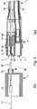
第1実施例を、図2を参照して以下説明する。図2の(a)は、(機器)制御(電力)供給ユニットからの供給パイプ1の先端に搭載されたユニバーサル・カップリング4を示す。(b)は、ユニバーサル・カップリング4に結合するよう配置されたバック・カップリング2の一部を示す。バック・カップリング2は、中間部品あるいはハンドピースの一部を形成し、さらにはまた供給パイプ1を介して供給され制御される別の装置を示し、例えば電気モータあるいは空気タービンを含む装置の一部を構成する。 The first embodiment will be described below with reference to FIG. FIG. 2 (a) shows a universal coupling 4 mounted at the tip of a supply pipe 1 from a (device) control (power) supply unit. (B) shows a part of the back coupling 2 arranged to be coupled to the universal coupling 4. The back coupling 2 forms an intermediate part or part of the handpiece and also represents another device that is supplied and controlled via the supply pipe 1, for example one of the devices including an electric motor or an air turbine. Parts.
カップリング4は、図1に記載したそれに類似するが、さらに電気ラインが追加されている。この実施例の場合アース・ラインが追加されている。図2に示す本体5は、絶縁性合成材料製で、圧縮空気用導管12用の凹型の流体コネクタ6と、戻り空気導管13用の凹型のコネクタ7とを有する。本体5は、ブッシング14に搭載される。ブッシング14は、回転ネジスリーブ10を搭載し、その後端は供給パイプ1を包囲する。供給パイプ1は、流体用の4本のフレキシブルなチューブを有する。すなわち、流体コネクタ6の後端に接続されたチューブ16と、コネクタ7の後端に接続された戻り空気チューブ17と、流体コネクタ8、9に接続された他のチューブである。さらに、供給パイプ1は、4本の絶縁された電気ラインを有し、それぞれ電気コネクタ20―23に接続される。供給パイプ1は、これら全てのチューブと電気ラインをカバーするフィレキシブルなシース18を有する。 Coupling 4 is similar to that described in FIG. 1, but with additional electrical lines. In this embodiment, a ground line is added. The body 5 shown in FIG. 2 is made of an insulating synthetic material and has a concave fluid connector 6 for the
供給パイプ1において、フレキシブルな導電体24は、戻り空気チューブ17内を自由に延び、例えば絶縁されていない銅製編素ワイヤで、アース・ラインを形成する。この導電体が、アース・ラインでない場合、あるいはアース・ラインを含む導管が導電性流体を流す場合には、絶縁導電体を使用する。この場合、アース・ラインを戻り空気チューブ17内に配置する。その理由は、戻り空気チューブ17が、最も太く、空気通路部分の縮小が最小となるからである。導電体24は、機械的且つ電気的(例えばクリッピングおよび/または溶接により)に、コネクタ7の後端部に結合される。コネクタ7は、戻り空気導管13内を、小さな中央スリーブの形態で、延びる。空気通路用の複数のオリフィス27を具備する円錐部分26は、スリーブ25を、コネクタ7のメイン管状部分30に結合する。このコネクタ7は、円筒状ボア28を有し、ユニバーサル・カップリング4の前面11に向いて開いている。コネクタ7は、良好な導電性材料、好ましくは金属製材料製で、そのメイン管状部分30の外部表面29は、漏れなく、戻り空気チューブ17に挿入される。その結果、コネクタ7は、空気コネクタおよび/または電気コネクタとして同時にあるいは交互に、ユニバーサル・カップリング4の前面11にさらなる場所を必要とすることなく、用いることができる。 In the supply pipe 1, the
導電体24とコネクタ7を含むアース・ライン(接地線)が大地に対し電位ゼロである場合には、その構成要素を絶縁する必要はない。かくして、アース・ラインは、作業領域にわたって吸い上げられた水滴で電荷がチャージされることがある戻り空気導管13内を通る戻り空気と接触することができる。アース・ラインは、水のような導電性流体を搬送するチューブを含む供給パイプ1内の他のチューブと組み合わせることもできる。 If the earth line (ground line) including the
この実施例においては、圧縮空気用導管12の流体コネクタ6は、従来と同様に形成されるが、空気搬送機能と導電機能の二重機能を持たせることもできる(コネクタ7のように)。この二重機能は、圧縮空気が乾燥状態にある場合、チューブ16内を通る電気制御/電力供給ライン(例えば他のチューブ内にある導電体24)と組み合わせて、持たせることもできる。供給パイプ1内に、2本のラインを含む新たな電気回路(ライン)を有することも可能である。この場合、流体コネクタ6は、絶縁しなければならない。 In this embodiment, the fluid connector 6 of the
図2の(b)に、本発明を実現するために特有なバック・カップリング2の要素のみを示す。凹型のコネクタ7と係合するために、流体用と電気用の二重機能を具備する凸型のコネクタ32が、カップリングの本体33内に搭載され、管状部品34を含む。この管状部品34は、本体33の前面35から突出し、コネクタ7の円筒状ボア28にはめ込まれる。その内側ボア36は、戻り空気導管13に接続される。円筒状ボア28の表面と共働するために、管状部品34の外側表面にはO−リング、あるいはシーリング・ガスケットを具備する。突起部分37が良好な電気的接触を提供する。凸型コネクタ32の他端は、ここでは先端部分であるが、コネクタ7のそれと同様に形成される。凸型コネクタ32の他端は、チューブ42内に延びる導電体41の端部に固定される小さな中央ブッシング40を具備する。チューブ42は、接続された機器からの戻り空気を搬送する。円錐切り欠き部分43は、中央ブッシング40と凸型コネクタの管状部品34とを固定し、好ましくは金属製である。 FIG. 2 (b) shows only the elements of the back coupling 2 that are specific for realizing the present invention. To engage the concave connector 7, a
コネクタ7において、スリーブ25と円錐部分26をメイン管状部分30の後端部を超えて配置することには、2つの利点がある。第1の利点は、この配置によりスリーブ25を容易に導電体24にクリップあるいは溶接できることであり、第2の利点は、スリーブ25と円錐部分26は、メイン管状部分30内に収納された凸型コネクタ32と干渉しない(ぶつからない)ことである。メイン管状部分30は、図1の従来の実施例よりも長くはない。すなわち本発明はユニバーサル・カップリング4をより長く形成する必要はない。 In the connector 7, placing the
バック・カップリング2は、さらにユニバーサル・カップリング4のコネクタの全てあるいは一部と共働する他の凸型(または凹型あるいはその両方の型)コネクタを有するが、これは、それに結合される機器によって決まる。例えば、凹型の流体コネクタ6が流体機能と電気機能の両方を有する場合、例えばコネクタ7の場合、対応する凸型のコネクタは、凸型コネクタ32と同様に、本体33のチャネル45内に搭載される。 The back coupling 2 further has other convex (or concave or both) connectors that cooperate with all or part of the connectors of the universal coupling 4, which is the equipment coupled to it. It depends on. For example, when the concave fluid connector 6 has both a fluid function and an electrical function, for example, in the case of the connector 7, the corresponding convex connector is mounted in the
バック・カップリング2と同一タイプのカップリングを有する現在の歯科用機器においては、本体33は通常金属製である。この実施例においても、凸型コネクタ32を通る電気ラインがアース・ラインである場合には、金属製である。しかし、バック・カップリング2内に配置された凸型コネクタ32あるいは他の同様のコネクタが、ゼロ電位ではないような電気ラインの一部を構成する場合には、本体33は、絶縁材料で形成しなければならない。 In current dental instruments having the same type of coupling as the back coupling 2, the
上記の記載において、供給パイプ1を介して供給される機器の種類によっては、二重機能のコネクタ7は、流体用と電気用の両方の機能を有するコネクタ(凸型コネクタ32)あるいは従来技術に記載したような専用の流体コネクタあるいは電気コネクタと係合できる。これは、供給される機器が戻り空気を必要としない場合、例えば電気モータを具備した外科用機器の場合である。かくしてユニバーサル・カップリング4は、利用範囲が拡がる。 In the above description, depending on the type of equipment supplied through the supply pipe 1, the dual function connector 7 is a connector having a function for both fluid and electricity (convex connector 32) or a conventional technique. Engage with dedicated fluid connectors or electrical connectors as described. This is the case when the instrument supplied does not require return air, for example a surgical instrument with an electric motor. Thus, the universal coupling 4 can be used in a wider range.
大部分の場合、二重機能のコネクタ内を通る追加的な第2電気ラインは、信号伝送用あるいは電力供給用のいずれにも用いることができる。 In most cases, an additional second electrical line running through the dual function connector can be used for either signal transmission or power supply.
図3、4は、2つの他の実施例を示すが、これらが第1実施例と異なる点は、関連する流体導管に対する追加的に配置された第2電気ラインの場所である。図面を単純化するためにこの違いのみを以下説明する。 3 and 4 show two other embodiments, which differ from the first embodiment in the location of an additional second electrical line with respect to the associated fluid conduit. Only this difference will be described below to simplify the drawing.
図3の実施例においては、導電体24、41は、戻り空気導管13内に配置されず、チューブ17、42の壁内に配置される。それぞれの端部は、ポイント50、51で、関連するコネクタの管状部分30、34の外側表面に溶接される。この導電体は、フレキシブルな金属製ストリップあるいは平坦な編組の形態を採り、押し出しによりチューブを製造する間、チューブの壁内に埋設される。このため、導電体24、41は、供給パイプ内を流れる流体から保護され、腐食の問題を回避できる。これらは、導管13内の空気通路断面積を減らすことはない。 In the embodiment of FIG. 3, the
図4の実施例においては、導電体24と41は、対応する戻り空気チューブ17と42の外側に配置され、そのため、それらは絶縁シースを有するのが好ましい。それぞれの端部は剥がされて、関連するコネクタのメイン管状部分30、34の外側表面にポイント50、51で溶接される。これは図3の実施例と同様である。この絶縁された導電体24は、供給パイプ1内に収納されるが、その方法は、電気コネクタ20−23に結合された導電体と同様である。その結果、コネクタを制御供給ユニットに接続するのと同様に、接続される。 In the embodiment of FIG. 4, the
図2b、3b、4bの凸型コネクタ32のいずれも、図2a、3a、4aの凹型のいずれにもプラグ・インされる。言い換えると、追加された第2導電体の配置は、2個の結合されたバック・カップリング2、ユニバーサル・カップリング4と同一である必要はない。 Any of the
図5は、図2の構造の変形例を部分的に示し、電気接触部材の配置が、前述した実施例とは異なる。この実施例においては、図2の戻り空気チューブ17が省かれているが、その理由は、供給パイプ1は、戻り空気導管を必要としない機器(電気モータを具備したハンドピース)用だからである。しかし、これらのハンドピースは、電力用あるいは制御用の信号を送信(例えば、モータにより生成される結合を示す信号、あるいはモータあるいは他の部材に電力を与えるために送信される電力)する電気ラインを必要とする。この電気ラインは、前述した実施例の導電体24、41により形成され、コネクタ7と凸型コネクタ32により互いに接続される。 FIG. 5 partially shows a modified example of the structure of FIG. 2, and the arrangement of the electrical contact members is different from the above-described embodiment. In this embodiment, the
凹型のコネクタ7は、絶縁本体5内に配置された円筒状ボア52を有し、その中にバック・カップリング2の円筒端部部分53が入る。円筒状ボア52内において、本体5は、円筒状ボア52の中心で金属製接点スリーブ55を搬送する凹んだ支持部分54を有する。金属製接点スリーブ55の先端部分には、弾性ストリップ57を規定するスロット56が具備される。支持部分54は、必要によっては、空気通路用のチャネル58を有する。金属製弾性ストリップ55の先端は、本体5の前面11から内側に入っている。導電体24の端部は、その絶縁シースが剥ぎ取られて、金属製弾性ストリップ55の後部に固定される。供給パイプ1内に戻り空気用のチューブがない場合には、導電体24はパイプのシース18内に収納するだけでよく、あるいは他の電気ラインに含ませてもよい。 The concave connector 7 has a cylindrical bore 52 disposed in the insulating body 5 into which the
凸型コネクタ32内において、導電体41は接触ピン60に結合される。この接触ピン60は、バック・カップリング2の本体33の要素(図示せず)に具備される。この接触ピン60は、円筒端部部分53により形成される導管の中央部にある。バック・カップリング2とユニバーサル・カップリング4が結合されると、接触ピン60は、金属製弾性ストリップ55内にプラグ・インされて、導電体24と41との間の電気接続を確保する。 Within the
図5に示された電気ピンとスリーブ接続システムは、図2に示された戻り空気導管13と一体に構成することもでき、且つチューブ17と42により、あるいはバック・カップリング2とユニバーサル・カップリング4の別の二重機能のコネクタにより、形成される。 The electrical pin and sleeve connection system shown in FIG. 5 can also be constructed in one piece with the
以上の説明は、本発明の一実施例に関するもので、この技術分野の当業者であれば、本発明の種々の変形例を考え得るが、それらはいずれも本発明の技術的範囲に包含される。特許請求の範囲の構成要素の後に記載した括弧内の番号は、図面の部品番号に対応し、発明の容易なる理解の為に付したものであり、発明を限定的に解釈するために用いてはならない。また、同一番号でも明細書と特許請求の範囲の部品名は必ずしも同一ではない。これは上記した理由による。 The above description relates to one embodiment of the present invention, and those skilled in the art can consider various modifications of the present invention, all of which are included in the technical scope of the present invention. The The numbers in parentheses described after the constituent elements of the claims correspond to the part numbers in the drawings, are attached for easy understanding of the invention, and are used for limiting the invention. Must not. In addition, the part numbers in the description and the claims are not necessarily the same even with the same number. This is for the reason described above.
1 供給パイプ
2 バック・カップリング
4 ユニバーサル・カップリング
5 本体
6−9 流体コネクタ
10 回転ネジスリーブ
11 前面
12 圧縮空気用導管
13 戻り空気導管
14 ブッシング
16 チューブ
17 戻り空気チューブ
18 シース
20−23 電気コネクタ
24 導電体
25 スリーブ
26 円錐部分
27 オリフィス
28 円筒状ボア
29 外部表面
30 メイン管状部分
32 凸型コネクタ
33 本体
34 管状部品
35 前面
36 内側ボア
37 突起部分
40 中央ブッシング
41 コンダクタ
42 チューブ
43 円錐切り欠き部分
45 チャネル
50,51 ポイント
52 円筒状ボア
53 円筒端部部分
54 凹部支持部分
55 金属製弾性ストリップ
56 スロット
57 弾性ストリップ
58 チャネル
60 接触ピンDESCRIPTION OF SYMBOLS 1 Supply pipe 2 Back coupling 4 Universal coupling 5 Main body 6-9
Claims (7)
Translated fromJapanese前記供給パイプは、流体導管と電気ラインとを有し、その先端に、ユニバーサル・カップリング(4)を有し、
前記ユニバーサル・カップリング(4)は、前記歯科/外科用器具を、取り外し可能に、前記流体導管と電気ラインの一部あるいは全てに接続し、
前記ユニバーサル・カップリング(4)は、前記流体導管に接続される流体コネクタ(6−9)と、前記電気ラインに接続される電気コネクタ(20−23)とを有し、
前記各コネクタは、ユニバーサル・カップリングの前面(11)の一領域を占有し、 前記供給パイプ(1)は、第2導電体(24)を有する少なくとも1個の第2電気ラインをさらに有し、
前記第2導電体(24)は、前記電気コネクタ(20−23)には接続されず、前記流体コネクタの1つ(7)に結合され、前記第2導電体(24)が結合された流体コネクタ(7)は、二重機能のコネクタを構成し、
前記二重機能のコネクタ(7)は、流体接続用あるいは電気接続用のいずれか、あるいはその両方の機能を実行し、
前記二重機能の流体コネクタ(7)は、金属製管状部分(30)を有し、
前記金属製管状部分(30)は、前記第2導電体(24)に電気的に接続され、前記パイプ内を延びるフレキシブルなチューブ(17)に結合され、前記チューブ(17)と共に流体導管(13)を形成し、
前記金属製管状部分(30)は、電気的接触部材と、前記歯科/外科用機器に接続されるコネクタの管状部分(32)に嵌る適合部材とを構成する
ことを特徴とする歯科/外科用機器を制御供給ユニットに接続する供給パイプ。In the supply pipe connecting the dental / surgical instrument to the control supply unit,
The supply pipe has a fluid conduit and an electrical line, and has a universal coupling (4) at its tip,
The universal coupling (4) removably connects the dental / surgical instrument to part or all of the fluid conduit and electrical line;
The universal coupling (4) has a fluid connector (6-9) connected to the fluid conduit and an electrical connector (20-23) connected to the electrical line;
Each connector occupies a region of the front surface of the universal coupling (11), and the supply pipe (1) further comprises at least one second electrical line having a second conductor (24). ,
The second conductor (24) is not connected to the electrical connector (20-23) but is coupled to one of the fluid connectors (7), and the second conductor (24) is coupled to the fluid. The connector (7) constitutes a dual function connector,
The dual function connector (7) performs the function of either fluid connection or electrical connection, or both,
The dual function fluid connector (7) has a metallic tubular portion (30);
The metallic tubular portion (30) is electrically connected to the second conductor (24), coupled to a flexible tube (17) extending through the pipe, and a fluid conduit (13) together with the tube (17). )
The metallic tubular portion (30) comprises an electrical contact member and a fitting member that fits into the tubular portion (32) of a connector connected to the dental / surgical instrument. A supply pipe connecting the dental / surgical instrument to the control supply unit.
ことを特徴とする請求項1記載の供給パイプ。The supply pipe according to claim 1, characterized in that the second conductor (24) is arranged in a fluid conduit (13) in the tube (17).
前記金属製スリーブ(25)は、前記金属製管状部分(30)に結合され、流体導管(13)内に配置される
ことを特徴とする請求項2記載の供給パイプ。The second conductor (24) is coupled to the metal sleeve (25),
The supply pipe according to claim 2, characterized in that the metallic sleeve (25) is coupled to the metallic tubular part (30) and is arranged in a fluid conduit (13).
ことを特徴とする請求項1記載の供給パイプ。The supply pipe according to claim 1, characterized in that the second conductor (24) is arranged in the wall of the tube (17).
ことを特徴とする請求項1記載の供給パイプ。The supply pipe according to claim 1, characterized in that the second conductor (24) is arranged outside the tube (17).
ことを特徴とする請求項1−5のいずれかに記載の供給パイプ。A supply pipe according to any of the preceding claims, wherein the conduit engaging the dual function connector (7) is an air conduit (13).
前記円筒状ボアは、前記ユニバーサル・カップリング(4)の絶縁体(5)内に配置され、
前記接触要素は、前記円筒状ボアの中心に配置され、前記第2導電体(24)に電気的に接続される
ことを特徴とする請求項1記載の供給パイプ。The dual function connector (7) has a cylindrical bore (52) and a contact element (55);
The cylindrical bore is disposed in an insulator (5) of the universal coupling (4);
The supply pipe according to claim 1, characterized in that the contact element is arranged in the center of the cylindrical bore and is electrically connected to the second conductor (24).
Applications Claiming Priority (3)
| Application Number | Priority Date | Filing Date | Title |
|---|---|---|---|
| EP04012687.2 | 2004-05-28 | ||
| EP04012687 | 2004-05-28 | ||
| PCT/EP2005/004987WO2005115264A1 (en) | 2004-05-28 | 2005-05-09 | Pipe and universal coupling for supplying dental or surgical instruments |
Publications (2)
| Publication Number | Publication Date |
|---|---|
| JP2008500078A JP2008500078A (en) | 2008-01-10 |
| JP4813468B2true JP4813468B2 (en) | 2011-11-09 |
Family
ID=34925165
Family Applications (1)
| Application Number | Title | Priority Date | Filing Date |
|---|---|---|---|
| JP2007513733AExpired - Fee RelatedJP4813468B2 (en) | 2004-05-28 | 2005-05-09 | Pipes and universal couplings for dental / surgical delivery equipment |
Country Status (9)
| Country | Link |
|---|---|
| US (1) | US8517731B2 (en) |
| EP (1) | EP1753360B1 (en) |
| JP (1) | JP4813468B2 (en) |
| CN (1) | CN100553584C (en) |
| DE (1) | DE602005003570T2 (en) |
| DK (1) | DK1753360T3 (en) |
| ES (1) | ES2297707T3 (en) |
| RU (1) | RU2373889C2 (en) |
| WO (1) | WO2005115264A1 (en) |
Families Citing this family (21)
| Publication number | Priority date | Publication date | Assignee | Title |
|---|---|---|---|---|
| EP1985905A1 (en)* | 2007-04-27 | 2008-10-29 | Fabrizio Nobili | Terminal unit for flexible hose to convey a fluid to a spray head |
| EP2277365B1 (en) | 2008-05-16 | 2011-11-02 | Parker-Hannifin Corporation | Modular high-power drive stack cooled with vaporizable dielectric fluid |
| DE202008014447U1 (en)* | 2008-10-30 | 2010-03-18 | Rehau Ag + Co | joint assembly |
| US8362665B2 (en)* | 2009-11-11 | 2013-01-29 | Remy Technologies, L.L.C. | Liquid cooled stator terminal block for an electric machine |
| DE102011050192A1 (en)* | 2011-05-06 | 2012-11-08 | Aesculap Ag | Surgical coupling system and surgical drive system |
| EP3738638A1 (en) | 2012-03-15 | 2020-11-18 | Fisher & Paykel Healthcare Limited | Respiratory gas humidification system |
| EP2642609A1 (en)* | 2012-03-23 | 2013-09-25 | Erbe Elektromedizin GmbH | Connector piece for a medical device or instrument |
| GB2575894A (en) | 2012-04-27 | 2020-01-29 | Fisher & Paykel Healthcare Ltd | Usability features for respiratory humidification system |
| CH706607A1 (en) | 2012-06-11 | 2013-12-13 | Dassym Sa | surgical, especially dental system. |
| DE102012106666B4 (en)* | 2012-07-23 | 2017-06-01 | MEDTRONIC medizinisch-elektronische Geräte-Gesellschaft mit beschränkter Haftung | Coupling device for connecting a supply hose for dental instruments with a supply and control unit |
| JP6663850B2 (en) | 2013-09-13 | 2020-03-13 | フィッシャー アンド ペイケル ヘルスケア リミテッド | Humidification system connection |
| GB2584026B (en) | 2013-09-13 | 2021-03-17 | Fisher & Paykel Healthcare Ltd | A heater base for supplying humidified gases to a patient |
| CN106029147B (en) | 2013-12-20 | 2020-01-21 | 费雪派克医疗保健有限公司 | Humidification system connection |
| US20150216622A1 (en)* | 2014-02-05 | 2015-08-06 | Albert Vartanian | Ergonomically optimized, in-line water valve assembly for use with a dental handpiece |
| US10449319B2 (en) | 2014-02-07 | 2019-10-22 | Fisher & Paykel Healthcare Limited | Respiratory humidification system |
| US11173272B2 (en) | 2014-05-02 | 2021-11-16 | Fisher & Paykel Healthcare Limited | Gas humidification arrangement |
| CN110124174A (en) | 2014-05-13 | 2019-08-16 | 费雪派克医疗保健有限公司 | Availability aspect for breathing humidification system |
| CN106535971B (en) | 2014-06-03 | 2020-12-04 | 费雪派克医疗保健有限公司 | Flow mixers for respiratory therapy systems |
| WO2016080847A1 (en) | 2014-11-17 | 2016-05-26 | Fisher & Paykel Healthcare Limited | Humidification of respiratory gases |
| EP3551978B1 (en) | 2016-12-07 | 2022-01-26 | Fisher&Paykel Healthcare Limited | Sensing arrangements for medical devices |
| DE102018126886A1 (en)* | 2018-10-19 | 2020-04-23 | Eugen Forschner Gmbh | Connection arrangement |
Citations (5)
| Publication number | Priority date | Publication date | Assignee | Title |
|---|---|---|---|---|
| EP0745358A1 (en)* | 1995-05-05 | 1996-12-04 | Bien-Air Sa | Multi-purpose attachment for connecting different types of dental instruments |
| JP2002035009A (en)* | 2000-07-19 | 2002-02-05 | Morita Mfg Co Ltd | Discriminating instrument body, discriminating adapter, discriminating tube, medical device using these |
| US20030031442A1 (en)* | 1999-01-13 | 2003-02-13 | Siegman Anthony E. | Fiber lasers having a complex-valued Vc-parameter for gain-guiding |
| US20030092324A1 (en)* | 2001-11-12 | 2003-05-15 | Walker Daniel H. | Electrical contact for fluid quick connectors |
| JP2004041587A (en)* | 2002-07-15 | 2004-02-12 | Morita Mfg Co Ltd | Connected body having communication function, medical treatment device using the same |
Family Cites Families (7)
| Publication number | Priority date | Publication date | Assignee | Title |
|---|---|---|---|---|
| US1890290A (en)* | 1932-02-26 | 1932-12-06 | William T Owens | Fire hose coupling |
| US3295514A (en)* | 1964-06-08 | 1967-01-03 | Dentists Supply Co | Electrical dental instrument assembly |
| DE2549177C3 (en)* | 1975-11-03 | 1985-10-03 | Siemens AG, 1000 Berlin und 8000 München | Coupling device for dental handpieces |
| FR2610511A1 (en)* | 1987-02-06 | 1988-08-12 | Issalene Robert | DENTAL INSTRUMENT AND CANNULAS FOR ASPIRATION, CLEANING, DRYING AND LIGHTING IN THE MOUTH |
| CH676081A5 (en) | 1988-06-08 | 1990-12-14 | Bien Air | Fluid and power coupler for dentist's hand tool - contg. supplementary electrical contacts conveying encoded pulses for recognition of non-standard DC or AC loads |
| DE60013095T2 (en)* | 2000-04-14 | 2005-09-01 | Bien-Air Holding S.A. | Quick connection rotary joint for connecting a dental tool to a supply source |
| EP1441659A1 (en)* | 2001-10-17 | 2004-08-04 | Dentsply International, Inc. | Unitized modular ultrasonic handpiece cable connector |
- 2005
- 2005-05-09JPJP2007513733Apatent/JP4813468B2/ennot_activeExpired - Fee Related
- 2005-05-09USUS11/568,867patent/US8517731B2/ennot_activeExpired - Fee Related
- 2005-05-09CNCNB2005800170124Apatent/CN100553584C/ennot_activeExpired - Fee Related
- 2005-05-09RURU2006146669/14Apatent/RU2373889C2/enactive
- 2005-05-09DEDE602005003570Tpatent/DE602005003570T2/ennot_activeExpired - Lifetime
- 2005-05-09EPEP05740643Apatent/EP1753360B1/ennot_activeExpired - Lifetime
- 2005-05-09ESES05740643Tpatent/ES2297707T3/ennot_activeExpired - Lifetime
- 2005-05-09DKDK05740643Tpatent/DK1753360T3/enactive
- 2005-05-09WOPCT/EP2005/004987patent/WO2005115264A1/enactiveIP Right Grant
Patent Citations (5)
| Publication number | Priority date | Publication date | Assignee | Title |
|---|---|---|---|---|
| EP0745358A1 (en)* | 1995-05-05 | 1996-12-04 | Bien-Air Sa | Multi-purpose attachment for connecting different types of dental instruments |
| US20030031442A1 (en)* | 1999-01-13 | 2003-02-13 | Siegman Anthony E. | Fiber lasers having a complex-valued Vc-parameter for gain-guiding |
| JP2002035009A (en)* | 2000-07-19 | 2002-02-05 | Morita Mfg Co Ltd | Discriminating instrument body, discriminating adapter, discriminating tube, medical device using these |
| US20030092324A1 (en)* | 2001-11-12 | 2003-05-15 | Walker Daniel H. | Electrical contact for fluid quick connectors |
| JP2004041587A (en)* | 2002-07-15 | 2004-02-12 | Morita Mfg Co Ltd | Connected body having communication function, medical treatment device using the same |
Also Published As
| Publication number | Publication date |
|---|---|
| EP1753360B1 (en) | 2007-11-28 |
| DE602005003570T2 (en) | 2008-11-27 |
| CN100553584C (en) | 2009-10-28 |
| EP1753360A1 (en) | 2007-02-21 |
| US8517731B2 (en) | 2013-08-27 |
| RU2373889C2 (en) | 2009-11-27 |
| HK1102908A1 (en) | 2007-12-07 |
| JP2008500078A (en) | 2008-01-10 |
| ES2297707T3 (en) | 2008-05-01 |
| CN1956685A (en) | 2007-05-02 |
| DE602005003570D1 (en) | 2008-01-10 |
| US20070248934A1 (en) | 2007-10-25 |
| RU2006146669A (en) | 2008-07-20 |
| WO2005115264A1 (en) | 2005-12-08 |
| DK1753360T3 (en) | 2008-03-31 |
Similar Documents
| Publication | Publication Date | Title |
|---|---|---|
| JP4813468B2 (en) | Pipes and universal couplings for dental / surgical delivery equipment | |
| US7011636B2 (en) | Electrically conductive coaxial guide wire | |
| US8579825B2 (en) | Electrically conductive guide wire | |
| WO1998020787A3 (en) | An endoscope wherein electrical components are electrically isolated from patient-engaging components | |
| JPS6159726B2 (en) | ||
| JP2013201129A (en) | Plug and socket connector part for medical device or instrument | |
| US4655709A (en) | Coupling device for dental handpieces | |
| CN110840375B (en) | Endoscope | |
| US20240115233A1 (en) | Radial ultrasound capsule and system | |
| CN209996428U (en) | Handle device for ultrasonic scalpel system | |
| JP5468958B2 (en) | Intracorporeal ultrasound system | |
| CN219051802U (en) | Extension sleeve and pipe cleaning nozzle and/or inspection nozzle with extension sleeve | |
| HK1102908B (en) | Pipe and universal coupling for supplying dental or surgical instruments | |
| CN115530921A (en) | Electrode lead for electrohydraulic stone breaking and electrohydraulic stone breaking device | |
| US11166784B2 (en) | Power generating system for a rotatory dental apparatus | |
| US20220104919A1 (en) | Power generating system for a rotatory dental apparatus | |
| JP3650224B2 (en) | Endoscope tube | |
| JP4178799B2 (en) | Ultrasonic probe | |
| CN219070515U (en) | Lithotripter device | |
| CN218978859U (en) | Insertion part and endoscope | |
| WO2006129359A1 (en) | Rotary self-traveling endoscope instrument | |
| JPWO2006126268A1 (en) | Rotating self-propelled endoscope device | |
| TW202341942A (en) | High-frequency electrode needle having temperature measurement function, and thermocouple connector | |
| JPS59198674A (en) | electrical connectors | |
| JP2002253482A (en) | Endoscope shape detecting probe |
Legal Events
| Date | Code | Title | Description |
|---|---|---|---|
| A621 | Written request for application examination | Free format text:JAPANESE INTERMEDIATE CODE: A621 Effective date:20080403 | |
| A131 | Notification of reasons for refusal | Free format text:JAPANESE INTERMEDIATE CODE: A131 Effective date:20110214 | |
| A601 | Written request for extension of time | Free format text:JAPANESE INTERMEDIATE CODE: A601 Effective date:20110513 | |
| A602 | Written permission of extension of time | Free format text:JAPANESE INTERMEDIATE CODE: A602 Effective date:20110520 | |
| A601 | Written request for extension of time | Free format text:JAPANESE INTERMEDIATE CODE: A601 Effective date:20110614 | |
| A602 | Written permission of extension of time | Free format text:JAPANESE INTERMEDIATE CODE: A602 Effective date:20110621 | |
| A521 | Request for written amendment filed | Free format text:JAPANESE INTERMEDIATE CODE: A523 Effective date:20110706 | |
| TRDD | Decision of grant or rejection written | ||
| A01 | Written decision to grant a patent or to grant a registration (utility model) | Free format text:JAPANESE INTERMEDIATE CODE: A01 Effective date:20110729 | |
| A01 | Written decision to grant a patent or to grant a registration (utility model) | Free format text:JAPANESE INTERMEDIATE CODE: A01 | |
| A61 | First payment of annual fees (during grant procedure) | Free format text:JAPANESE INTERMEDIATE CODE: A61 Effective date:20110824 | |
| R150 | Certificate of patent or registration of utility model | Ref document number:4813468 Country of ref document:JP Free format text:JAPANESE INTERMEDIATE CODE: R150 Free format text:JAPANESE INTERMEDIATE CODE: R150 | |
| FPAY | Renewal fee payment (event date is renewal date of database) | Free format text:PAYMENT UNTIL: 20140902 Year of fee payment:3 | |
| R250 | Receipt of annual fees | Free format text:JAPANESE INTERMEDIATE CODE: R250 | |
| R250 | Receipt of annual fees | Free format text:JAPANESE INTERMEDIATE CODE: R250 | |
| R250 | Receipt of annual fees | Free format text:JAPANESE INTERMEDIATE CODE: R250 | |
| R250 | Receipt of annual fees | Free format text:JAPANESE INTERMEDIATE CODE: R250 | |
| R250 | Receipt of annual fees | Free format text:JAPANESE INTERMEDIATE CODE: R250 | |
| R250 | Receipt of annual fees | Free format text:JAPANESE INTERMEDIATE CODE: R250 | |
| R250 | Receipt of annual fees | Free format text:JAPANESE INTERMEDIATE CODE: R250 | |
| R250 | Receipt of annual fees | Free format text:JAPANESE INTERMEDIATE CODE: R250 | |
| LAPS | Cancellation because of no payment of annual fees |