JP4811711B2 - Lens barrel and imaging device - Google Patents
Lens barrel and imaging deviceDownload PDFInfo
- Publication number
- JP4811711B2 JP4811711B2JP2005327271AJP2005327271AJP4811711B2JP 4811711 B2JP4811711 B2JP 4811711B2JP 2005327271 AJP2005327271 AJP 2005327271AJP 2005327271 AJP2005327271 AJP 2005327271AJP 4811711 B2JP4811711 B2JP 4811711B2
- Authority
- JP
- Japan
- Prior art keywords
- lens group
- lens
- optical axis
- frame
- moved
- Prior art date
- Legal status (The legal status is an assumption and is not a legal conclusion. Google has not performed a legal analysis and makes no representation as to the accuracy of the status listed.)
- Expired - Fee Related
Links
- 238000003384imaging methodMethods0.000titleclaimsdescription26
- 230000003287optical effectEffects0.000claimsdescription94
- 239000011295pitchSubstances0.000claimsdescription9
- 238000005452bendingMethods0.000claimsdescription2
- 238000010586diagramMethods0.000description14
- 239000000470constituentSubstances0.000description4
- 230000004888barrier functionEffects0.000description3
- 230000008859changeEffects0.000description3
- 230000000694effectsEffects0.000description2
- 230000007246mechanismEffects0.000description2
- 230000009467reductionEffects0.000description2
- 230000008901benefitEffects0.000description1
- 239000003990capacitorSubstances0.000description1
- 230000000295complement effectEffects0.000description1
- 238000001514detection methodMethods0.000description1
- 230000006870functionEffects0.000description1
- 238000003780insertionMethods0.000description1
- 230000037431insertionEffects0.000description1
- 229910044991metal oxideInorganic materials0.000description1
- 150000004706metal oxidesChemical class0.000description1
- 238000000034methodMethods0.000description1
- 230000004044responseEffects0.000description1
- 239000004065semiconductorSubstances0.000description1
- 229910052724xenonInorganic materials0.000description1
- FHNFHKCVQCLJFQ-UHFFFAOYSA-Nxenon atomChemical compound[Xe]FHNFHKCVQCLJFQ-UHFFFAOYSA-N0.000description1
Images


Classifications
- G—PHYSICS
- G03—PHOTOGRAPHY; CINEMATOGRAPHY; ANALOGOUS TECHNIQUES USING WAVES OTHER THAN OPTICAL WAVES; ELECTROGRAPHY; HOLOGRAPHY
- G03B—APPARATUS OR ARRANGEMENTS FOR TAKING PHOTOGRAPHS OR FOR PROJECTING OR VIEWING THEM; APPARATUS OR ARRANGEMENTS EMPLOYING ANALOGOUS TECHNIQUES USING WAVES OTHER THAN OPTICAL WAVES; ACCESSORIES THEREFOR
- G03B17/00—Details of cameras or camera bodies; Accessories therefor
- G03B17/02—Bodies
- G03B17/17—Bodies with reflectors arranged in beam forming the photographic image, e.g. for reducing dimensions of camera
- G—PHYSICS
- G02—OPTICS
- G02B—OPTICAL ELEMENTS, SYSTEMS OR APPARATUS
- G02B7/00—Mountings, adjusting means, or light-tight connections, for optical elements
- G02B7/02—Mountings, adjusting means, or light-tight connections, for optical elements for lenses
- G02B7/04—Mountings, adjusting means, or light-tight connections, for optical elements for lenses with mechanism for focusing or varying magnification
- G02B7/10—Mountings, adjusting means, or light-tight connections, for optical elements for lenses with mechanism for focusing or varying magnification by relative axial movement of several lenses, e.g. of varifocal objective lens
- G02B7/102—Mountings, adjusting means, or light-tight connections, for optical elements for lenses with mechanism for focusing or varying magnification by relative axial movement of several lenses, e.g. of varifocal objective lens controlled by a microcomputer
- G—PHYSICS
- G03—PHOTOGRAPHY; CINEMATOGRAPHY; ANALOGOUS TECHNIQUES USING WAVES OTHER THAN OPTICAL WAVES; ELECTROGRAPHY; HOLOGRAPHY
- G03B—APPARATUS OR ARRANGEMENTS FOR TAKING PHOTOGRAPHS OR FOR PROJECTING OR VIEWING THEM; APPARATUS OR ARRANGEMENTS EMPLOYING ANALOGOUS TECHNIQUES USING WAVES OTHER THAN OPTICAL WAVES; ACCESSORIES THEREFOR
- G03B13/00—Viewfinders; Focusing aids for cameras; Means for focusing for cameras; Autofocus systems for cameras
- G03B13/32—Means for focusing
- G03B13/34—Power focusing
Landscapes
- Physics & Mathematics (AREA)
- General Physics & Mathematics (AREA)
- Engineering & Computer Science (AREA)
- General Engineering & Computer Science (AREA)
- Optics & Photonics (AREA)
- Lens Barrels (AREA)
Description
Translated fromJapanese本発明は、屈曲した撮像光学系を内包し、所定のレンズ群を移動させるレンズ駆動装置を有したレンズ鏡胴及び撮像装置に関するものである。The present invention relates to a lens barrel including a bent imaging optical system and having a lens driving device that moves a predetermined lens group,and an imaging device .
従来より、ズームレンズを搭載したカメラが市販されている。ズームレンズは、光学系を構成する複数のレンズ群を光軸に沿って所望の位置に移動させて、その間隔を変化させることにより、焦点距離の変更(ズーミング)を行うようになっている。 Conventionally, cameras equipped with a zoom lens are commercially available. The zoom lens is configured to change the focal length (zooming) by moving a plurality of lens groups constituting the optical system to a desired position along the optical axis and changing the interval therebetween.
レンズ群を光軸に沿って移動させる方式としては大別して2種有り、レンズ枠を直進案内に係合させ、カム筒やヘリコイドを回転させることによりレンズ枠を直進移動させるものと、光軸に略平行に軸を配置しこの軸を直進案内のガイド軸とし、レンズ枠にガイド軸が貫通するスリーブを形成し、モータとリードスクリューを用いて直接的にレンズ枠をガイド軸に沿って摺動させ直進移動させるものがある。また、これらのレンズ群を移動させるための駆動源としては、DCモータやステッピングモータが一般的に用いられている。 There are roughly two types of methods for moving the lens group along the optical axis. The lens frame is engaged with the linear guide, and the lens frame is moved linearly by rotating the cam cylinder or helicoid. A shaft is arranged almost in parallel, and this shaft is used as a guide shaft for linear guide. A sleeve through which the guide shaft passes is formed in the lens frame, and the lens frame is slid directly along the guide shaft using a motor and a lead screw There is something that lets you move straight ahead. A DC motor or a stepping motor is generally used as a drive source for moving these lens groups.
一方、光学系中に反射面を配置し、光軸を折り曲げた所謂屈曲光学系が知られている。このような屈曲した撮像光学系を備えたカメラは、撮影時にカメラ前面からレンズ鏡胴が突出せず、ズーミングを行ってもカメラの形態が変化しない利点を有している。 On the other hand, a so-called bent optical system is known in which a reflecting surface is disposed in an optical system and the optical axis is bent. A camera having such a bent imaging optical system has an advantage that the lens barrel does not protrude from the front of the camera during shooting, and the form of the camera does not change even when zooming is performed.
この屈曲した撮像光学系を用いたカメラにおいても、外形は小型薄型化が求められ、内蔵される撮像光学系はより高変倍化が求められている。しかしながら、撮像光学系を高変倍化すると光学系全長が大きくなる傾向は避けられない。 Also in a camera using the bent imaging optical system, the outer shape is required to be small and thin, and the built-in imaging optical system is required to have higher magnification. However, when the image pickup optical system is highly variable in magnification, the total length of the optical system tends to increase.
このような要求に対し、複数の反射面を配置して、光軸が同一平面内に収まらないように複数回折り曲げた撮像光学系として、これを内蔵するカメラの外形を小型化したものがある(例えば、特許文献1参照)。
上記特許文献1に記載のデジタルカメラは、高変倍のズームレンズを外形の小さいカメラに収納できるものである。しかしながら、ズームレンズの光軸を複数回折り曲げ、ズーミング時に移動するレンズ群が同一直線でない光軸上でそれぞれ移動するように配置した場合、レンズ群の移動を行うに際し、それぞれのレンズ群に対し個別に駆動源を配置するとコスト高となるばかりか、レンズ鏡胴の大型化を招く問題がある。 The digital camera described in
本発明は上記問題に鑑み、光軸を複数回折り曲げて構成したズームレンズの、ズーミング時に移動するレンズ群が同一直線でない光軸上に配置されている場合でも、低コストでより小型化したレンズ鏡胴及び撮像装置を得ることを目的とするものである。 In view of the above-described problems, the present invention is a zoom lens that is configured by bending a plurality of optical axes, and even when a lens group that moves during zooming is arranged on an optical axis that is not collinear, it is a low-cost and more compact lens. The object is to obtain a lens barrel and an imaging device.
上記の目的は、下記に記載する発明により達成される。 The above object is achieved by the invention described below.
1.被写体光の入射する第1の光軸を折り曲げる第1の反射面と、前記第1の反射面による折り曲げ後の第2の光軸に沿って移動可能となされたレンズ群と、前記第2の光軸を更に折り曲げる第2の反射面と、前記第2の反射面による折り曲げ後の第3の光軸を、前記第2の光軸に沿って平行となるように折り曲げる第3の反射面と、前記第3の反射面による折り曲げ後の第4の光軸に沿って移動可能となされたレンズ群と、前記第2の光軸と前記第4の光軸の間に配置された雄ネジ部材と前記雄ネジ部材を駆動するモータと、を有し、前記雄ネジ部材は、ピッチの異なる第1のネジ溝と第2のネジ溝が一体的に形成され、前記モータの駆動により前記雄ネジ部材を回転させ、前記第1のネジ溝によって前記第2の光軸に沿って移動可能となされたレンズ群を移動させると共に、前記第2のネジ溝によって前記第4の光軸に沿って移動可能となされたレンズ群を異なる移動量で移動させるよう構成したことを特徴とするレンズ鏡胴。1.Afirst reflecting surface thatbendsthe first optical axis on whichsubject light is incident;a lens group that is movable along the second optical axis after being bent by the first reflecting surface; andthe second group A second reflecting surface that further bends the optical axis, and a third reflecting surface that bends the third optical axis after being bent by the second reflecting surface to be parallel to the second optical axis; A lens group that is movable along the fourth optical axis after being bent by the third reflecting surface, and a male screw member disposed between the second optical axis and the fourth optical axis. And a motor for driving the male screw member, wherein the male screw member is integrally formed with a first screw groove and a second screw groove having different pitches, and the male screw is driven by driving the motor. The member is rotated, and can be moved along the second optical axis by the first screw groove. Moves the lens group, the second thread groove by the lens barrel, characterized bybeing configured to move by the movement amount different movable and made a lens group along the fourth optical axis.
2.前記第1のネジ溝と前記第2のネジ溝の進み方向が同じで、前記第1のネジ溝のピッチが前記第2のネジ溝のピッチより大きいことを特徴とする1に記載のレンズ鏡胴。2.2. The lens mirror according to 1, whereinthe first screw groove and the second screw groove have the same advancing direction, and the pitch of the first screw groove is larger than the pitch of the second screw groove. Torso.
3.1又は2に記載のレンズ鏡胴を備えたことを特徴とする撮像装置。3 . An imaging apparatus comprising the lens barrel according to 1or 2 .
本発明によれば、ズーミング時に移動するレンズ群が同一直線でない光軸上に配置された撮像光学系の場合にも、低コストでより小型化したレンズ鏡胴及び撮像装置を得ることが可能となる。 According to the present invention, it is possible to obtain a lens barrel and an imaging apparatus that are more compact at a lower cost even in the case of an imaging optical system in which lens groups that move during zooming are arranged on optical axes that are not collinear. Become.
以下、実施の形態により本発明を詳しく説明するが、本発明はこれに限定されるものではない。 Hereinafter, the present invention will be described in detail with reference to embodiments, but the present invention is not limited thereto.
(第1の実施の形態)
以下、第1の実施の形態に係るレンズ鏡胴及び撮像装置について説明する。(First embodiment)
Hereinafter, the lens barrel and the imaging apparatus according to the first embodiment will be described.
図1は、第1の実施の形態に係るレンズ鏡胴を備えた撮像装置の一例である、カメラ100の主要構成ユニットの内部配置の一例を示す図である。同図は、カメラ100を被写体側斜め上方から見た斜視図である。 FIG. 1 is a diagram illustrating an example of an internal arrangement of main constituent units of a
同図に示すように、カメラ100は、変倍可能な折り曲げ撮像光学系を内包したレンズ鏡胴50が図示の如く右側に縦に配置され、開口部51が被写体光束を取り込むよう配置されている。この開口部51には、開口部51を露呈する開状態と開口部51を覆う閉状態とする図示しないレンズバリアが設けられている。 As shown in the figure, in the
52はフラッシュ発光窓であり、53はフラッシュ発光窓の後方に配置された反射傘、キセノン管、その他メインコンデンサ、回路基板等で構成されるフラッシュユニットである。54はカード型の画像記録用メモリである。55は電池であり、本カメラの各部へ電源を供給する。画像記録用メモリ54及び電池55は、図示しない蓋部から挿脱が可能となっている。
本カメラの上面には、レリーズ釦56が配置され、その1段の押し込みによりカメラの撮影準備動作、即ち焦点合わせ動作や測光動作が行われ、その2段の押し込みにより撮影露光動作が行われる。57はメインスイッチであり、カメラを動作状態と非動作状態に切り替えるスイッチである。メインスイッチ57により動作状態に切り替えられると、図示しないレンズバリアは、開状態にされると共に、各部の動作が開始される。また、メインスイッチ57により非動作状態に切り替えられると、図示しないレンズバリアは、閉状態にされると共に、各部の動作を終了させる。 A
本カメラの背面には、LCD或いは有機EL等で構成され、画像やその他文字情報等を表示する画像表示部58が配置されている。また、図示していないが、ズームアップ、ズームダウンをおこなうズーム釦、撮影した画像を再生する再生釦、画像表示部58上に各種のメニューを表示させるメニュー釦、表示から所望の機能を選択する選択釦等の操作部材が配置されている。 On the back side of the camera, an
なお、不図示であるが、これら主要構成ユニットの間には、各部を接続すると共に、各種電子部品が搭載された回路基板が配置され、各主要構成ユニットの駆動及び制御を行うようになっている。同様に、不図示の、外部入出力端子、ストラップ取り付け部、三脚座等を備えている。 Although not shown, a circuit board on which various electronic components are mounted is arranged between these main constituent units, and each main constituent unit is driven and controlled. Yes. Similarly, an external input / output terminal, a strap attaching portion, a tripod seat, and the like (not shown) are provided.
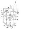
図2は、第1の実施の形態に係るレンズ鏡胴50の内部の変倍可能な折り曲げ撮像光学系を示す模式図である。同図(a)は被写体光の入射する光軸OAと、光軸OAが折り曲げられた後の光軸OBを含む面で切断した模式的な断面を示し、同図(b)は光軸OBと、光軸OBが折り曲げられた後の光軸OCと、光軸OCが折り曲げられた後の光軸ODを含む面で切断した模式的な断面を示している。同図(c)は同図(b)に示すF−F線で切断した模式的な断面を示している。なお、同図においては、移動する各レンズ群を直進案内するガイド部材を省略して示してある。また、以下の図においては、説明の重複を避けるため、同機能部材には同符号を付与して説明する。 FIG. 2 is a schematic diagram showing a foldable imaging optical system capable of zooming inside the
同図において、1は第1レンズ群であり、第1レンズ群1は光軸をOAとし被写体に向けて配置されたレンズ11、反射面を有した反射部材R1、レンズ12で構成されている。この反射部材R1により、光軸OAは光軸OB方向に折り曲げられる。この第1レンズ群1は固定されたレンズ群である。 In the figure,
2は第2レンズ群であり、第2レンズ群鏡枠2kに組み込まれている。第2レンズ群は、変倍(以下、ズーミングとも言う)時に第2レンズ群鏡枠2kと共に、一体的に移動するレンズ群である。
第2レンズ群2の後方には、反射面を有した反射部材R2が配置され、この反射部材R2により、光軸OBは光軸OC方向に折り曲げられる。 A reflecting member R2 having a reflecting surface is disposed behind the
3は第3レンズ群であり、固定されたレンズ群である。Sは絞りシャッタユニットである。
第3レンズ群3の後方には、反射面を有した反射部材R3が配置され、この反射部材R3により、光軸OCは光軸OD方向に折り曲げられる。 A reflective member R3 having a reflective surface is disposed behind the
4は第4レンズ群であり、第4レンズ群鏡枠4kに組み込まれている。第4レンズ群は、変倍時に第4レンズ群鏡枠4kと共に、一体的に移動するレンズ群である。
5は第5レンズ群であり、第5レンズ群鏡枠5kに組み込まれている。第5レンズ群5は、変倍時及び焦点調節(以下、フォーカシングとも言う)時に第5レンズ群鏡枠5kと共に、一体的に移動するレンズ群である。
6は赤外光カットフィルタ及びオプチカルローパスフィルタを積層した光学フィルタである。7は撮像素子であり、CCD(Charge Coupled Device)型イメージセンサ、CMOS(Complementary Metal−Oxide Semiconductor)型イメージセンサ等が用いられる。撮像素子7は不図示のフレキシブルプリント基板に接続され、カメラ内の他の回路へ接続される。
第2レンズ群2、第4レンズ群4、第5レンズ群5は、同図(b)に示すワイド状態の位置から、第3レンズ群3に近接する方向へ、各々設定された量だけ移動しズーミングが行われる。更に、第5レンズ群5は、ズーミングにより移動した位置から更に移動することによりフォーカシングを行うようになっている。 The
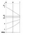
図3は、ズーミング時の各レンズ群の移動線図である。同図は、各レンズ群の移動を模式的に示すものであり、破線は反射部材R1、R2、R3の反射面の位置を示し、縦軸の数字はそれぞれレンズ群を示している。 FIG. 3 is a movement diagram of each lens group during zooming. This figure schematically shows the movement of each lens group, the broken lines indicate the positions of the reflecting surfaces of the reflecting members R1, R2, and R3, and the numbers on the vertical axis indicate the lens groups, respectively.
同図に示すように、第1レンズ群1、第3レンズ群3は固定レンズ群であり、第2レンズ群2、第4レンズ群4、第5レンズ群5はワイド(W)〜テレ(T)の間を図示の如く移動してズーミングが行われる。なお、第5レンズ群5はズーミングで移動した位置から更に移動してフォーカシングも行うようになっている。 As shown in the figure, the
図2に戻り、21は第1モータであり、22は第2モータである。第1モータ21、第2モータ22は、例えばステッピングモータであり、不図示のプリント基板に接続され、個々に制御及び駆動されるようになっている。 Returning to FIG. 2, 21 is a first motor and 22 is a second motor. The
第1モータ21には、回転軸に雄ネジ部材であるリードスクリュー21rが形成されている。このリードスクリュー21rには、1本の軸に、ネジの進み方向は同じであって、ピッチが異なる第1のネジ溝21r1、第2のネジ溝21r2が形成されている。この第1、第2のネジ溝21r1、21r2を有したリードスクリュー21rは、それぞれ個別に製作し接合して一体化したものでもよいし、一体の軸を加工したものでもよい。The
第1のネジ溝21r1には、図示の如く第2レンズ群鏡枠2kに形成された雌ネジ部が螺合し、第2のネジ溝21r2には、図示の如く第4レンズ群鏡枠4kに形成された雌ネジ部が螺合している。なお、第1のネジ溝21r1、第2のネジ溝21r2にそれぞれ雌ネジ部材を螺合させ、この雌ネジ部材と第2レンズ群鏡枠2k及び第4レンズ群鏡枠4kをそれぞれ係合させる構成でもよい。The
第1モータ21の所定の方向の回転により、第2レンズ群2と第4レンズ群4は異なる移動量で双方から第3レンズ群3に接近し、第1モータ21の逆方向の回転により、異なる移動量で共に第3レンズ群3から離間するように移動する。これにより、第2レンズ群2と第4レンズ群4は図3の移動線図に示す移動をすることができる。 Due to the rotation of the
即ち、第1モータ21により、第2レンズ群2は光軸OB上を移動し、第4レンズ群4は反射面により折り曲げられた、光軸OBとは同一直線でない光軸OD上を移動する。これにより、1つのモータで2つのレンズ群を移動させることができ、レンズ鏡胴を低コスト化することができる。 That is, the
また、反射部材R2、R3により光軸OB、ODを略平行とし、第1モータ21を光軸OB、ODの間の空間に配置することにより、小型のレンズ鏡胴とすることができる。 Further, by making the optical axes OB and OD substantially parallel by the reflecting members R2 and R3 and disposing the
一方、第2モータ22も、同図(c)に示すように略平行な光軸OB、ODの間の空間に配置されており、第5レンズ群5を図3の移動線図に示した移動を行わせる。このように、略平行の光軸OB、ODの間の空間に第1モータ21、第2モータ22を共に配置することで、更に小型のレンズ鏡胴とすることができる。 On the other hand, the
図4は、レンズ鏡胴50内の第5レンズ群を移動させる機構を模式的に示した図である。なお、同図においても、移動するレンズ群を案内するガイド軸を省略して示してある。 FIG. 4 is a diagram schematically showing a mechanism for moving the fifth lens group in the
同図に示すように、第2モータ22には、回転軸に雄ネジ部材であるリードスクリュー22rが形成されている。リードスクリュー22rには図示の如く第5レンズ群鏡枠5kに形成された雌ネジ部が螺合している。なお、リードスクリュー22rに雌ネジ部材を螺合させ、この雌ネジ部材と第5レンズ群鏡枠5kを係合させる構成でもよい。 As shown in the figure, the
この第5レンズ群5は、第2モータ22により、ズーミング及びズーミングにより移動した位置から更に移動することでフォーカシングを行う。 The
なお、不図示であるが、2つのフォトインタラプタが設けられており、第2レンズ群鏡枠2kと第4レンズ群鏡枠4kのいずれか一方と第5レンズ群鏡枠5kに形成された遮蔽部の挿脱切り替わり位置を検出することにより初期位置検出が行われるようになっている。この初期位置を基準にして第1モータ21、第2モータ22の回転方向及び回転量をそれぞれ独立に制御し、各レンズ群の位置制御が行われるようになっている。なお、各レンズ群鏡枠の初期位置検出は、フォトリフレクタであってもよい。 Although not shown, two photointerrupters are provided, and a shield formed on one of the second
なお、上記の第1の実施の形態においては、第1のネジ溝21r1と第2のネジ溝21r2のネジ進み方向が同じで、ピッチの異なるもので説明したが、これに限るものでなく、共に異なっているものや、ネジ進み方向とピッチの両方が同じものでもよいのは勿論であり、これらは、使用する撮像光学系の仕様に基づいて適宜選択されるものである。また、両方が同じものの場合には、第2レンズ群鏡枠2kと第4レンズ群鏡枠4kを一体化して形成することもできる。In the first embodiment, the
図5は、第1の実施の形態に係るレンズ鏡胴50における、第2レンズ群鏡枠と第4レンズ群鏡枠を一体化して形成した例を示す図である。 FIG. 5 is a diagram illustrating an example in which the second lens group lens frame and the fourth lens group lens frame are integrally formed in the
同図に示すように、第2レンズ群2と第4レンズ群4は、一体の鏡枠8kに組み付けられている。鏡枠8kは図示の如く第1モータ21のリードスクリュー21rに螺合しており、リードスクリュー21rの回転により、第2レンズ群2は光軸OBに沿って移動し、第4レンズ群4は光軸ODに沿って移動する。この場合には、リードスクリュー21rの回転に対する、それぞれのレンズ群の移動量は同じとなる。なお、第5レンズ群鏡枠5kの移動に関しては図4に示したものと同様である。 As shown in the figure, the
このように、2つのレンズ群を一体的に形成された鏡枠に組み付け、単一のリードスクリュー21rにより移動させるよう構成することにより、より低コストなレンズ鏡胴を得ることが可能となる。 In this way, it is possible to obtain a lower-cost lens barrel by assembling the two lens groups on the integrally formed lens frame and moving the lens group by the
(第2の実施の形態)
以下、第2の実施の形態に係るレンズ鏡胴及び撮像装置について説明する。(Second Embodiment)
Hereinafter, a lens barrel and an imaging apparatus according to the second embodiment will be described.
図6は、第2の実施の形態に係るレンズ鏡胴を備えた撮像装置の一例である、カメラ100の主要構成ユニットの内部配置の一例を示す図である。同図は、カメラ100を被写体側斜め上方から見た斜視図である。同図については、図1に示したものと異なる部分についてのみ説明する。 FIG. 6 is a diagram illustrating an example of an internal arrangement of main constituent units of the
第2の実施の形態に係るレンズ鏡胴50は、被写体に向かう光軸OAが、まず図示のカメラ100の側面に沿って下方へ折り曲げられたのち、底面で横方向に再度り曲げられた全体としてL字型をしたものである。 In the
図7は、第2の実施の形態に係るレンズ鏡胴50の内部の変倍可能な折り曲げ撮像光学系を示す模式図である。同図(a)は被写体光の入射する光軸OAと、光軸OAが折り曲げられた後の光軸OBを含む面で切断した被写体光入射部の模式的な部分断面を示し、同図(b)は光軸OBと、光軸OBが折り曲げられた後の光軸OCとを含む面で切断した模式的な断面を示している。なお、本例も移動する各レンズ群を直進案内するガイド部材を省略して示してある。 FIG. 7 is a schematic diagram showing a foldable imaging optical system capable of zooming inside the
同図に示す撮像光学系については、第1レンズ群1、第3レンズ群3は固定レンズ群であり、第2レンズ群2、第4レンズ群4、第5レンズ群5はワイド(W)〜テレ(T)の間では、それぞれ移動してズーミングが行われる。なお、第5レンズ群5はズーミングで移動した位置から更に移動してフォーカシングも行うようになっている。 In the imaging optical system shown in the figure, the
同図に示すように、第2レンズ群鏡枠2kの外周には略120°間隔でカムピン2pが一体的に形成されており、このカムピン2pが係合するカム溝が形成されたカム筒20が設けられている。カム筒20は、回動可能に支持されており、カム筒20の回動により、不図示の直進案内を行うガイド部材にガイドされて、第2レンズ群鏡枠2kは、光軸OB方向に直進移動可能となっている。 As shown in the drawing, cam pins 2p are integrally formed on the outer periphery of the second
第4レンズ群鏡枠4kに形成された雌ネジ部は、リードスクリュー21rに螺合し、不図示の回転係止がなされており、第1モータ21の回転即ちリードスクリュー21rの回転により、第4レンズ群鏡枠4k即ち第4レンズ群4は光軸OC方向に移動させられる。 The female thread portion formed on the fourth lens
第1モータ21は、第4レンズ群鏡枠4kが螺合するリードスクリュー21rと、このリードスクリュー21rに一体的に形成された歯車部21gを備えている。歯車部21gの回転は、減速歯車22、23により減速され、減速歯車23と同軸に形成された傘歯車23pを回転させる。傘歯車23pと歯合する傘歯車部が形成されたカム筒20は、この傘歯車23pの回転により回動し、第2レンズ群鏡枠2kは光軸OB方向に直進移動する。 The
即ち、第1モータ21の回転駆動により、光軸OB上に位置する第2レンズ群2及び、反射部材R2により折り曲げられた光軸OC上に位置する第4レンズ群を移動させるようになっている。本例のように、2つのレンズ群のうち、いずれか一方をカムにより移動させるようにすることで、カムにより移動させるレンズ群の移動量変化の設定が自由にできるようになり、レンズ設計の自由度を増加させることができる。 That is, the
なお、第5レンズ群5は、不図示の第2モータにより、ズーミング及びズーミングにより移動した位置から更に移動することでフォーカシングを行うようになっている。 The
図8は、第2の実施の形態に係るレンズ鏡胴50の別の例を示す図である。同図は、第2レンズ群鏡枠2kの移動を板状のカム部材で行うようにした例を示している。なお、本例も移動する各レンズ群を直進案内するガイド部材を省略して示してある。同図に示すレンズ鏡胴50は、図6と異なる部分についてのみ説明する。 FIG. 8 is a diagram illustrating another example of the
同図に示すように、第1モータ21のリードスクリュー21rには、ナット21nが螺合しており、このナット21nは不図示の回転係止がなされ、リードスクリュー21rの回転により、光軸OC方向に直進移動するようになっている。ナット21nにはピン21pが形成されている。また、第2レンズ群鏡枠2kには、ピン2pが形成されている。 As shown in the figure, a
25は板状のカム部材(ベルクランクとも称す)であり、26は軸である。軸26によりベルクランク25は回動可能に軸止されている。ベルクランク25には、ピン21pが係合する長溝25m1及びピン2pが係合する長溝25m2が形成されている。
第1モータ21によりリードスクリュー21rを回転させ、光軸OC上の第4レンズ群鏡枠4kを第3レンズ群3に接近させる方向に移動させると、ナット21nも紙面右方向に移動する。このナット21nの図示右方向の移動に伴って、ベルクランク25は軸26周りに図示矢印で示す時計周り方向に回動し、長溝25m2に係合するピン2pを反射部材R2方向に移動させ、不図示のガイド部材に沿って第2レンズ群鏡枠2kを第3レンズ群3に接近させる方向に移動させるようになっている。When the
一方、上記の第2レンズ群2及び第4レンズ群4が第3レンズ群に接近した状態から、リードスクリュー21rを逆方向に回転させると、光軸OC上の第4レンズ群鏡枠4kは第3レンズ群3から離間する方向に移動し、ナット21nも紙面左方向に移動する。このナット21nの紙面左方向の移動に伴って、ベルクランク25は軸26周りに図示矢印と逆の反時計周り方向に回動し、長溝25m2に係合するピン2pを第1レンズ群1の方向に移動させ、不図示のガイド部材に沿って第2レンズ群鏡枠2kを第3レンズ群3から離間する方向に移動させることができる。On the other hand, when the
このように、反射面により折り曲げられた、同一直線でない光軸上にそれぞれ位置する2つのレンズ群のうち一方のレンズ群を、板状のカム部材を用いて移動させるようにすることで図7に示したレンズ鏡胴と同様の効果を得つつ、図7に示したレンズ鏡胴よりも低コストのレンズ鏡胴とすることができる。 In this way, by moving one lens group of the two lens groups, which are bent on the reflecting surface and located on the optical axes that are not collinear, by using a plate-like cam member, FIG. While obtaining the same effect as the lens barrel shown in FIG. 7, the lens barrel can be made at a lower cost than the lens barrel shown in FIG.
図9は、第2の実施の形態に係るレンズ鏡胴50のその他の例を示す図である。同図も、第2レンズ群鏡枠2kの移動を板状のカム部材で行うようにした例を示している。なお、本例も移動する各レンズ群を直進案内するガイド部材を省略して示してある。同図に示すレンズ鏡胴50については、図8と異なる部分についてのみ説明する。 FIG. 9 is a diagram illustrating another example of the
同図に示すように、第4レンズ群鏡枠4kには、ピン4pが一体的に形成されている。 As shown in the figure, a
25はベルクランクであり、26は軸である。軸26によりベルクランク25は回動可能に軸止されている。ベルクランク25には、ピン4pが係合する長溝25m1及びピン2pが係合する長溝25m2が形成されている。25 is a bell crank and 26 is a shaft. The
第1モータ21によりリードスクリュー21rを回転させ、光軸OC上の第4レンズ群鏡枠4kを第3レンズ群3に接近させる方向に移動させると、第4レンズ群鏡枠4kに一体的に形成されたピン4pにより、ベルクランク25は軸26周りに図示時計周り方向に回動し、長溝25m2に係合するピン2pを反射部材R2方向に移動させ、不図示のガイド部材に沿って第2レンズ群鏡枠2kを第3レンズ群3に接近させる方向に移動させるようになっている。When the
一方、上記の第2レンズ群2及び第4レンズ群4が第3レンズ群に接近した状態から、リードスクリュー21rを逆方向に回転させると、光軸OC上の第4レンズ群鏡枠4kは第3レンズ群3から離間する方向に移動し、ピン4pも紙面左方向に移動する。このピン4pの紙面左方向の移動に伴って、ベルクランク25は軸26周りに反時計周り方向に回動し、長溝25m2に係合するピン2pを第1レンズ群1の方向に移動させ、不図示のガイド部材に沿って第2レンズ群鏡枠2kを第3レンズ群3から離間する方向に移動させることができる。On the other hand, when the
このようにすることで、同様の効果を得つつ、図8に示したレンズ鏡胴よりも部品点数を削減でき、更なる低コスト化されたレンズ鏡胴を得ることが可能となる。 By doing in this way, while obtaining the same effect, the number of parts can be reduced as compared with the lens barrel shown in FIG. 8, and it is possible to obtain a lens barrel with further reduced cost.
また、上記の第2の実施の形態においては、第2レンズ群鏡枠2kをカムを用いて移動させ、第4レンズ群鏡枠4kをリードスクリュー21rに螺合させて移動させるもので説明したが、これに限るものでなく、仕様に応じて第2レンズ群鏡枠2kをリードスクリュー21rに螺合させて移動させ、第4レンズ群鏡枠4kをカムを用いて移動させるようにしてもよいのは勿論である。 In the second embodiment, the second
また、第2の実施の形態で説明した、一方のレンズ群をカムにより移動させる構成は、図2に示す、光軸が略平行である場合にも適用可能であるのはいうまでもない。 Needless to say, the configuration of moving one lens group by the cam described in the second embodiment is also applicable to the case where the optical axes shown in FIG. 2 are substantially parallel.
また、上記の第1の実施の形態及び第2の実施の形態においては、反射部材に平面鏡を用いた例で説明したが、プリズム等を適宜用いてもよいのは勿論である。また、1つの駆動源で移動させられる2つのレンズ群を共に、カムにより移動するよう構成してもよいのは勿論である。 In the first embodiment and the second embodiment described above, the example in which the plane mirror is used as the reflecting member has been described, but it is needless to say that a prism or the like may be used as appropriate. Of course, the two lens groups that are moved by one drive source may be configured to move together by a cam.
1 第1レンズ群
2 第2レンズ群
2k 第2レンズ群鏡枠
3 第3レンズ群
4 第4レンズ群
4k 第4レンズ群鏡枠
5 第5レンズ群
5k 第5レンズ群鏡枠
6 光学フィルタ
7 撮像素子
20 カム筒
21 第1モータ
21r リードスクリュー
22 第2モータ
22r リードスクリュー
25 板状のカム部材(ベルクランク)
26 軸
50 レンズ鏡胴
100 カメラ(撮像装置)
OA、OB、OC、OD 光軸
R1、R2、R3 反射部材
S 絞りシャッタユニットDESCRIPTION OF
26
OA, OB, OC, OD Optical axis R1, R2, R3 Reflective member S Aperture shutter unit
Claims (3)
Translated fromJapanese前記第1の反射面による折り曲げ後の第2の光軸に沿って移動可能となされたレンズ群と、
前記第2の光軸を更に折り曲げる第2の反射面と、
前記第2の反射面による折り曲げ後の第3の光軸を、前記第2の光軸に沿って平行となるように折り曲げる第3の反射面と、
前記第3の反射面による折り曲げ後の第4の光軸に沿って移動可能となされたレンズ群と、
前記第2の光軸と前記第4の光軸の間に配置された雄ネジ部材と前記雄ネジ部材を駆動するモータと、を有し、
前記雄ネジ部材は、ピッチの異なる第1のネジ溝と第2のネジ溝が一体的に形成され、
前記モータの駆動により前記雄ネジ部材を回転させ、前記第1のネジ溝によって前記第2の光軸に沿って移動可能となされたレンズ群を移動させると共に、前記第2のネジ溝によって前記第4の光軸に沿って移動可能となされたレンズ群を異なる移動量で移動させるよう構成したことを特徴とするレンズ鏡胴。Afirst reflecting surface that bendsthe first optical axis on whichsubject light is incident;
A lens group that is movable along the second optical axis after being bent by the first reflecting surface;
A second reflecting surface for further bending the second optical axis;
A third reflecting surface that bends the third optical axis after being bent by the second reflecting surface so as to be parallel along the second optical axis;
A lens group that is movable along the fourth optical axis after being bent by the third reflecting surface;
A male screw member disposed between the second optical axis and the fourth optical axis, and a motor for driving the male screw member,
The male screw member is formed integrally with a first screw groove and a second screw groove having different pitches,
The male screw member is rotated by driving the motor, the lens group that is movable along the second optical axis is moved by the first screw groove, and the first screw groove is used to move the lens group. 4. A lens barrel characterized inthat the lens group made movable along the optical axis 4 is moved by different amounts of movement .
Priority Applications (2)
| Application Number | Priority Date | Filing Date | Title |
|---|---|---|---|
| JP2005327271AJP4811711B2 (en) | 2005-11-11 | 2005-11-11 | Lens barrel and imaging device |
| US11/594,078US7532418B2 (en) | 2005-11-11 | 2006-11-08 | Lens barrel and image pickup apparatus |
Applications Claiming Priority (1)
| Application Number | Priority Date | Filing Date | Title |
|---|---|---|---|
| JP2005327271AJP4811711B2 (en) | 2005-11-11 | 2005-11-11 | Lens barrel and imaging device |
Publications (2)
| Publication Number | Publication Date |
|---|---|
| JP2007133214A JP2007133214A (en) | 2007-05-31 |
| JP4811711B2true JP4811711B2 (en) | 2011-11-09 |
Family
ID=38040515
Family Applications (1)
| Application Number | Title | Priority Date | Filing Date |
|---|---|---|---|
| JP2005327271AExpired - Fee RelatedJP4811711B2 (en) | 2005-11-11 | 2005-11-11 | Lens barrel and imaging device |
Country Status (2)
| Country | Link |
|---|---|
| US (1) | US7532418B2 (en) |
| JP (1) | JP4811711B2 (en) |
Families Citing this family (5)
| Publication number | Priority date | Publication date | Assignee | Title |
|---|---|---|---|---|
| JP4822992B2 (en)* | 2006-09-08 | 2011-11-24 | 富士フイルム株式会社 | Lens barrel |
| JP2010078958A (en)* | 2008-09-26 | 2010-04-08 | Konica Minolta Opto Inc | Lens barrel and imaging apparatus |
| US8242444B2 (en)* | 2009-04-15 | 2012-08-14 | Exelis, Inc. | Ganged focus mechanism for an optical device |
| JP6969459B2 (en)* | 2018-03-15 | 2021-11-24 | オムロン株式会社 | The sensor head |
| TWI791206B (en)* | 2021-03-31 | 2023-02-01 | 圓展科技股份有限公司 | Dual lens movement control system and method |
Family Cites Families (8)
| Publication number | Priority date | Publication date | Assignee | Title |
|---|---|---|---|---|
| JP3265091B2 (en)* | 1993-11-30 | 2002-03-11 | キヤノン株式会社 | Compound eye imaging system |
| JPH08297326A (en)* | 1995-04-25 | 1996-11-12 | Canon Inc | Compound camera |
| JPH09211287A (en)* | 1996-01-31 | 1997-08-15 | Canon Inc | Imaging device |
| JPH1164707A (en)* | 1997-08-13 | 1999-03-05 | Fuji Photo Optical Co Ltd | Zoom lens barrel |
| JPH11258678A (en)* | 1998-03-11 | 1999-09-24 | Olympus Optical Co Ltd | Lens barrel |
| JP2004133053A (en)* | 2002-10-08 | 2004-04-30 | Olympus Corp | Lens barrel |
| JP2005300562A (en)* | 2003-05-12 | 2005-10-27 | Konica Minolta Opto Inc | Camera |
| JP3991227B2 (en)* | 2003-11-12 | 2007-10-17 | 船井電機株式会社 | Optical head device |
- 2005
- 2005-11-11JPJP2005327271Apatent/JP4811711B2/ennot_activeExpired - Fee Related
- 2006
- 2006-11-08USUS11/594,078patent/US7532418B2/ennot_activeExpired - Fee Related
Also Published As
| Publication number | Publication date |
|---|---|
| JP2007133214A (en) | 2007-05-31 |
| US20070109671A1 (en) | 2007-05-17 |
| US7532418B2 (en) | 2009-05-12 |
Similar Documents
| Publication | Publication Date | Title |
|---|---|---|
| KR100900486B1 (en) | Optical module for imaging device and imaging device having same | |
| JP4028721B2 (en) | Electronic camera | |
| US7369333B2 (en) | Lens unit and image capturing apparatus | |
| JP2010266678A (en) | Image capturing apparatus | |
| US7532418B2 (en) | Lens barrel and image pickup apparatus | |
| JP4910454B2 (en) | Lens barrel and imaging device | |
| JP2002287224A (en) | Digital camera | |
| JP2009192581A (en) | Lens-barrel and imaging apparatus | |
| JP2008046200A (en) | Lens barrel and imaging apparatus | |
| JP2006133366A (en) | Lens barrel, camera equipped with lens barrel and method for assembling lens barrel | |
| US6973261B2 (en) | Camera | |
| JP2007072067A (en) | Lens barrel and imaging apparatus | |
| JP2007121494A (en) | Lens barrel and imaging apparatus | |
| JP2009181102A (en) | Lens barrel and imaging device | |
| JP2008076813A (en) | Lens barrel and imaging apparatus | |
| JP2010266749A (en) | Lens barrel and imaging apparatus | |
| JP2005037548A (en) | Photographic lens device and camera | |
| JP2010078958A (en) | Lens barrel and imaging apparatus | |
| JP4873134B2 (en) | Lens barrel and imaging device | |
| JP2007132989A (en) | Lens barrel and imaging apparatus | |
| JP2009169243A (en) | Lens barrel and imaging apparatus | |
| JP2007086139A (en) | Lens drive device, lens barrel, and imaging apparatus | |
| JP2007206155A (en) | Lens barrel and imaging apparatus | |
| JP2008003452A (en) | Lens barrel and imaging apparatus | |
| JP2007156068A (en) | Lens barrel and imaging apparatus |
Legal Events
| Date | Code | Title | Description |
|---|---|---|---|
| A621 | Written request for application examination | Free format text:JAPANESE INTERMEDIATE CODE: A621 Effective date:20081028 | |
| A977 | Report on retrieval | Free format text:JAPANESE INTERMEDIATE CODE: A971007 Effective date:20110117 | |
| A131 | Notification of reasons for refusal | Free format text:JAPANESE INTERMEDIATE CODE: A131 Effective date:20110125 | |
| RD03 | Notification of appointment of power of attorney | Free format text:JAPANESE INTERMEDIATE CODE: A7423 Effective date:20110215 | |
| A521 | Written amendment | Free format text:JAPANESE INTERMEDIATE CODE: A523 Effective date:20110308 | |
| TRDD | Decision of grant or rejection written | ||
| A01 | Written decision to grant a patent or to grant a registration (utility model) | Free format text:JAPANESE INTERMEDIATE CODE: A01 Effective date:20110729 | |
| A01 | Written decision to grant a patent or to grant a registration (utility model) | Free format text:JAPANESE INTERMEDIATE CODE: A01 | |
| A61 | First payment of annual fees (during grant procedure) | Free format text:JAPANESE INTERMEDIATE CODE: A61 Effective date:20110811 | |
| R150 | Certificate of patent or registration of utility model | Free format text:JAPANESE INTERMEDIATE CODE: R150 | |
| FPAY | Renewal fee payment (event date is renewal date of database) | Free format text:PAYMENT UNTIL: 20140902 Year of fee payment:3 | |
| S111 | Request for change of ownership or part of ownership | Free format text:JAPANESE INTERMEDIATE CODE: R313111 | |
| R350 | Written notification of registration of transfer | Free format text:JAPANESE INTERMEDIATE CODE: R350 | |
| LAPS | Cancellation because of no payment of annual fees |