JP4809919B2 - Gas concentration measuring instrument - Google Patents
Gas concentration measuring instrumentDownload PDFInfo
- Publication number
- JP4809919B2 JP4809919B2JP2009501650AJP2009501650AJP4809919B2JP 4809919 B2JP4809919 B2JP 4809919B2JP 2009501650 AJP2009501650 AJP 2009501650AJP 2009501650 AJP2009501650 AJP 2009501650AJP 4809919 B2JP4809919 B2JP 4809919B2
- Authority
- JP
- Japan
- Prior art keywords
- detection paper
- gas
- concentration measuring
- cassette
- gas concentration
- Prior art date
- Legal status (The legal status is an assumption and is not a legal conclusion. Google has not performed a legal analysis and makes no representation as to the accuracy of the status listed.)
- Expired - Fee Related
Links
Images


Classifications
- G—PHYSICS
- G01—MEASURING; TESTING
- G01N—INVESTIGATING OR ANALYSING MATERIALS BY DETERMINING THEIR CHEMICAL OR PHYSICAL PROPERTIES
- G01N21/00—Investigating or analysing materials by the use of optical means, i.e. using sub-millimetre waves, infrared, visible or ultraviolet light
- G01N21/75—Systems in which material is subjected to a chemical reaction, the progress or the result of the reaction being investigated
- G01N21/77—Systems in which material is subjected to a chemical reaction, the progress or the result of the reaction being investigated by observing the effect on a chemical indicator
- G01N21/78—Systems in which material is subjected to a chemical reaction, the progress or the result of the reaction being investigated by observing the effect on a chemical indicator producing a change of colour
- G01N21/783—Systems in which material is subjected to a chemical reaction, the progress or the result of the reaction being investigated by observing the effect on a chemical indicator producing a change of colour for analysing gases
- B—PERFORMING OPERATIONS; TRANSPORTING
- B01—PHYSICAL OR CHEMICAL PROCESSES OR APPARATUS IN GENERAL
- B01L—CHEMICAL OR PHYSICAL LABORATORY APPARATUS FOR GENERAL USE
- B01L2300/00—Additional constructional details
- B01L2300/08—Geometry, shape and general structure
- B01L2300/0809—Geometry, shape and general structure rectangular shaped
- B01L2300/0812—Bands; Tapes
- G—PHYSICS
- G01—MEASURING; TESTING
- G01N—INVESTIGATING OR ANALYSING MATERIALS BY DETERMINING THEIR CHEMICAL OR PHYSICAL PROPERTIES
- G01N31/00—Investigating or analysing non-biological materials by the use of the chemical methods specified in the subgroup; Apparatus specially adapted for such methods
- G01N31/22—Investigating or analysing non-biological materials by the use of the chemical methods specified in the subgroup; Apparatus specially adapted for such methods using chemical indicators
- G01N31/223—Investigating or analysing non-biological materials by the use of the chemical methods specified in the subgroup; Apparatus specially adapted for such methods using chemical indicators for investigating presence of specific gases or aerosols
- G01N31/224—Investigating or analysing non-biological materials by the use of the chemical methods specified in the subgroup; Apparatus specially adapted for such methods using chemical indicators for investigating presence of specific gases or aerosols for investigating presence of dangerous gases
Landscapes
- Physics & Mathematics (AREA)
- Chemical & Material Sciences (AREA)
- Engineering & Computer Science (AREA)
- Chemical Kinetics & Catalysis (AREA)
- Plasma & Fusion (AREA)
- Health & Medical Sciences (AREA)
- Life Sciences & Earth Sciences (AREA)
- Analytical Chemistry (AREA)
- Biochemistry (AREA)
- General Health & Medical Sciences (AREA)
- General Physics & Mathematics (AREA)
- Immunology (AREA)
- Pathology (AREA)
- Investigating Or Analyzing Non-Biological Materials By The Use Of Chemical Means (AREA)
- Investigating Or Analysing Materials By The Use Of Chemical Reactions (AREA)
- Packaging Of Annular Or Rod-Shaped Articles, Wearing Apparel, Cassettes, Or The Like (AREA)
Description
Translated fromJapanese本発明は、空気中に含まれているオゾンガス、二酸化窒素ガス等の特定の種類のガスの濃度を測定するガス濃度測定器に関するものである。 The present invention relates to a gas concentration measuring device for measuring the concentration of a specific type of gas such as ozone gas or nitrogen dioxide gas contained in air.
現在、NOx、SPM、光化学オキシダントによる大気汚染が生じ、環境に対する影響が大きな問題となってきている。光化学オキシダントの主成分であるオゾンガス(O3 )は、工場、事業所や自動車から排出されるNOxや炭化水素などの汚染物質が太陽光線の照射を受けて光化学反応を起こすと生成されるため、光化学スモッグの原因となっている。また、コロナ放電手段を備えた各種機器、例えば静電式複写機、レーザープリンタ、LEDファクシミリ等の装置においても、コロナ放電手段の動作中にオゾンガスやNOxガスが発生する。このようなオゾンガスは、強力な酸化能を有しているためそれ自身の毒性により空気中の濃度が一定以上(0.1ppm)になると、呼吸器系を刺激し、微量でも長時間吸入すると有害とされている。また、NOxガスは大気汚染の原因物質であり、呼吸器系疾患との関係も指摘されている。At present, air pollution due to NOx, SPM, and photochemical oxidants occurs, and the influence on the environment has become a major problem. Ozone gas (O3 ), the main component of photochemical oxidants, is generated when pollutants such as NOx and hydrocarbons emitted from factories, offices, and automobiles undergo photochemical reactions when exposed to sunlight. Causes photochemical smog. In various devices including corona discharge means, such as electrostatic copying machines, laser printers, and LED facsimiles, ozone gas and NOx gas are generated during the operation of the corona discharge means. Since such ozone gas has a strong oxidizing ability, if its concentration in the air exceeds a certain level (0.1 ppm) due to its own toxicity, it stimulates the respiratory system and is harmful if inhaled for a long time even in trace amounts. It is said that. In addition, NOx gas is a causative substance of air pollution, and a relationship with respiratory diseases has been pointed out.
このため、オゾンガスやNOXガスの濃度分布の調査や、地域環境への影響評価、個人のオゾンガスやNOXガス被爆の影響評価などを行って、環境を監視する必要がある。このために、オゾンガスについては安価で小型軽量かつ個人や家庭レベルで使用することができるオゾン濃度測定器が各種開発されている。例えば、特開2004−144729号公報、WO2006/016623(PCT/JP2005/014689)号公報、特開平09−274032号公報、特開2000−081426号公報等に開示されたオゾン濃度測定器が知られている。Therefore, it is necessary to monitor the environment by investigating the concentration distribution of ozone gas and NOx gas, evaluating the influence on the local environment, and evaluating the influence of personal ozone gas and NOx gas exposure. For this reason, various ozone concentration measuring devices have been developed for ozone gas that are inexpensive, small and light, and can be used at an individual or household level. For example, JP 2004-144729discloses, WO2006 / 0 1 6623 (PCT / JP2005 / 014689) , JP-A No. 09-274032, JP-2000-081426 Patent ozone concentration measuring device disclosed in such publication is Are known.
図14に従来のオゾン濃度測定器の一例を示す。このオゾン濃度測定器1は、オゾンガスに曝露されると変色(退色)する曝露部3を有するガス検知素子2と、オゾンガスの濃度に対応した色(色見本)を示すカラーチャート5が表示された台紙4とを備えている。ガス検知素子2は、台紙4にカラーチャート5に沿って固定されている。 FIG. 14 shows an example of a conventional ozone concentration measuring device. The ozone
ガス検知素子2は、通常オゾンガスに反応すると変色する色素、保湿剤、酸、水等を加えて調整した検知溶液をセルロース濾紙に含浸させて風乾することにより作製される。オゾンガスに反応すると変色する色素としては、インジゴ色素、アゾ色素、トリフェニルメタン色素、アントラキン色素等が用いられる。 The
台紙4は、通常ガス検知素子2と同一の材質によって形成されていることが望ましい。カラーチャート5は、それぞれ異なったオゾン濃度、例えば0ppb、400ppbおよび800ppbに対応する3つの色見本5a〜5cで構成されている。オゾン濃度が0ppbの色見本5aは、測定前のガス検知素子2の曝露部3と同じ色(インジゴカルミン:藍色)を呈している。これに対して、ガス濃度が高い色見本5b、5cほど退色している。 The
このようなオゾン濃度測定器1は、オゾンガスが存在する環境下で一定時間(例えば、8時間)使用すると、ガス検知素子2の曝露部3がオゾンガスによって曝露されることにより変色する。この変色した色とカラーチャート5の色見本5a〜5cとを見比べることにより、オゾンガスの濃度を知ることができる。すなわち、曝露部3が変色して400ppbの色見本5bと略等しい色に退色したときは、オゾン濃度が400ppbであると判定し、400ppbと800ppbの中間の色と略等しい色に退色したときは、オゾン濃度が600ppbであると判定する。 When such an ozone concentration measuring
しかしながら、上記した従来のオゾン濃度測定器1は、カード状に形成されているため、1回の測定毎に新しいものと交換しなければならず、連続的に使用することができないという問題があった。
また、保管しておく際にはガス検知素子2の曝露部3が外気に触れないようにアルミニウム等の密封された容器に一枚ずつ入れて保存している。そのため、測定のたびに密閉容器から取り出す必要があり、その手間が煩わしいという問題もあった。However, since the conventional ozone
Further, when storing, the exposed
本発明は上記した従来の問題を解決するためになされたものであり、その目的とするところは、取り扱いが容易で保管に必要な密閉性を保ちつつ連続的な測定を可能にしたガス濃度測定器を提供することにある。 The present invention has been made in order to solve the above-described conventional problems, and the object of the present invention is to measure the gas concentration, which is easy to handle and allows continuous measurement while maintaining the sealing required for storage. Is to provide a vessel.
上記目的を達成するために本発明は、カセット本体と、前記カセット本体の背面を覆うカバープレートとを有するカセットと、ロール状に巻回されて前記カセット内に収納され特定ガスに反応すると変色するテープ状のガス検知紙と、前記ガス検知紙を巻取る検知紙巻取り手段とを具備し、前記カセットは、前記カセット本体の前記背面に形成された未使用の前記ガス検知紙を収納する未使用検知紙収納部と、使用済みの前記ガス検知紙を収納する使用済み検知紙収納部と、前記未使用検知紙収納部と前記使用済み検知紙収納部を接続する検知紙用通路と、前記カセット本体の上面に形成され前記検知紙用通路の一部が前記カセットの外部に露呈する曝露部と、前記カセット本体と前記カバープレートとの接合面間に介在され前記未使用検知紙収納部の周囲を気密にシールするシール部材と、前記検知紙用通路の前記曝露部より上流側の通路部分に設けられ前記ガス検知紙を前記上流側通路部分の壁面に押し付けるシール手段とを有し、前記検知紙用通路の曝露部より上流側の通路部分に、ガス検知紙の次期測定部分を予め測定環境の湿気になじませる前処理部と、前記前処理部を大気に選択的に開放するシャッターをさらに設けたものである。In order to achieve the above object, the present invention changes color when a cassette having a cassette body, a cover plate covering the back of the cassette body, and wound in a roll shape is stored in the cassette and reacts with a specific gas. A tape-shaped gas detection paper and a detection paper winding means for winding the gas detection paper are provided, and the cassette stores unused gas detection paper formed on the back surface of the cassette body. A detection paper storage unit, a used detection paper storage unit for storing the used gas detection paper, a detection paper path connecting the unused detection paper storage unit and the used detection paper storage unit, and the cassette An unused portion formed between an exposed portion formed on an upper surface of the main body and exposing a part of the passage for the detection paper to the outside of the cassette, and the cassette main body and the cover plate. Yes and the seal member for sealing the periphery of the housing part hermetically, and a sealing means for pressing the gas detecting sheet provided on the passage portion of the upstream side of the exposure portion of the passage for the detection paper on the wall of the upstream passage portionIn addition, a pre-processing unit that preliminarily adjusts the next measurement portion of the gas detection paper to the humidity of the measurement environment and the pre-processing unit are selectively opened to the atmosphere in the passage portion upstream of the exposure portion of the detection paper passage. A shutter is further provided .
本発明に係るガス濃度測定器においては、未使用検知紙収納部と検知紙用通路の曝露部より上流側の通路部分を気密にシールしているので、未使用のガス検知紙がカセット外部の大気に晒されることがない。したがって、ガス検知紙をアルミニウムの包装袋に密閉して保管しておく必要がなく、ガス検知紙の保管、取り扱いが容易である。また、ガス検知紙はテープ状に形成されてロール状に巻回されているので、検知紙巻取り手段によって巻取ることにより連続的に使用することができる。 In the gas concentration measuring apparatus according to the present invention, the unused detection paper storage section and the passage portion upstream of the detection paper passage exposure section are hermetically sealed, so that the unused gas detection paper is placed outside the cassette. It is not exposed to the atmosphere. Therefore, it is not necessary to store the gas detection paper sealed in an aluminum packaging bag, and the gas detection paper can be easily stored and handled. Further, since the gas detection paper is formed in a tape shape and wound in a roll shape, the gas detection paper can be continuously used by being wound by the detection paper winding means.
また、本発明においては、検知紙用通路の曝露部より上流側通路部分に、ガス検知紙の次期測定部分を予め測定環境の湿気になじませる前処理部と、この前処理部を大気に選択的に開放するシャッターをさらに設けてもよい。 Further, in the present invention, a pre-processing unit that preliminarily adjusts the next measurement portion of the gas detection paper to the humidity of the measurement environment in the upstream passage portion from the exposed portion of the detection paper passage, and this pre-processing portion is selected as the atmosphere. A shutter that opens automatically may be provided.
また、本発明においては、前処理部がカセットの上面に開放する開口部を有し、シャッターをカセットの上面にスライド自在に設け、開口部を開閉するようにしてもよい。 In the present invention, the pre-processing unit may have an opening that opens on the upper surface of the cassette, and a shutter may be slidably provided on the upper surface of the cassette to open and close the opening.
また、本発明においては、カバープレートが前処理部に連通する連通孔を有し、シャッターが通気孔を有してカバープレートに回転自在に設けられ、連通孔と通気孔を介して前処理部を大気に開放させるようにしてもよい。 In the present invention, the cover plate has a communication hole that communicates with the pretreatment section, the shutter has a vent hole, and is provided rotatably on the cover plate. The pretreatment section is provided via the communication hole and the vent hole. May be opened to the atmosphere.
また、本発明においては、曝露部と前処理部との間に仕切壁を設けるとともに、この仕切壁の下面にガス検知紙を押し付ける押圧手段をさらに設けてもよい。 Moreover, in this invention, while providing a partition wall between an exposure part and a pre-processing part, you may further provide the press means which presses a gas detection paper to the lower surface of this partition wall.
また、本発明においては、シャッターをガス検知紙の前処理部に待機している次期測定部分が測定のために曝露部に送られる一定時間前に動作させることにより前処理部を大気に開放するようにしてもよい。 Further, in the present invention, the pretreatment unit is opened to the atmosphere by operating the shutter for a predetermined time before the next measurement unit waiting for the gas detection paper pretreatment unit is sent to the exposure unit for measurement. You may do it.
また、本発明においては、検知紙用通路の曝露部より上流側通路部分にガス検知紙の次期測定部分を予め測定環境になじませる前処理部と、この前処理部の開口部を覆い特定ガスを除去し湿気を通過させるフィルターをさらに設けてもよい。 Further, in the present invention, a pre-processing unit that preliminarily adjusts the next measurement portion of the gas detection paper to the passage portion upstream from the exposure portion of the detection paper passage, and a specific gas covering the opening of the pre-processing unit. A filter that removes moisture and allows moisture to pass therethrough may be further provided.
また、本発明においては、前処理部をカセット本体の前面および背面に開放する開口部と、カバープレートに形成された開口部とによって外部に連通させるようにしてもよい。 In the present invention, the pretreatment unit may be communicated with the outside through an opening that opens to the front and back of the cassette body and an opening formed in the cover plate.
さらに、本発明においては、ガス検知紙によって検出される特定ガスがオゾンガスであり、フィルターが、オゾンガスを除去するオゾンフィルターとメンブレンフィルターのうちのいずれか一方としてもよい。 Furthermore, in the present invention, the specific gas detected by the gas detection paper may be ozone gas, and the filter may be any one of an ozone filter that removes ozone gas and a membrane filter.
以下、本発明を図面に示す実施例に基づいて詳細に説明する。
[第1の実施例]
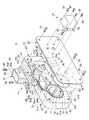
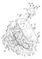
図1〜図3において、本発明は、遠隔操作によって大気中のオゾンガスの濃度を自動的に測定するオゾン濃度測定器10に適用した例を示す。また、このオゾン濃度測定器10は、請求項1に記載の測定器を示すもので、カセット12に収納されたガス検知紙11と、このガス検知紙11を巻取る検知紙巻取り手段13と、オゾン濃度を測定するガス濃度測定手段14等を備えている。Hereinafter, the present invention will be described in detail based on embodiments shown in the drawings.
[First embodiment]
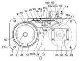
1 to 3 show an example in which the present invention is applied to an ozone
図4において、ガス検知紙11は、オゾンガスに曝露されると変色(退色または発色)して可視領域の吸収が変化する色素を含んだ検知溶液をテープ状担体、例えばセルロース濾紙に含浸させ、この含浸させた溶液を乾燥させて全体を曝露部とすることによりテープ状に形成されている。 In FIG. 4, a
検知溶液としては、オゾンガスに曝露されると変色する色素(例えば、インジゴ環)と、酸(例えば、クエン酸)と、保湿剤(例えば、グリセリン)とが溶解した水溶液が用いられる。インジゴ環を有する色素としては、例えばインジゴ、インジゴカルミンナトリウム塩、インジゴカルミンカリウム塩、インジゴレッドなどを用いることができる。酸としては、クエン酸、酢酸、リン酸、酒石酸などを用いることができる。酸は、検知溶液のpHを2〜4の範囲に保持するために用いられる。保湿剤としては、グリセリン、エチレングリコール、プロピレングリコールなどを用いることができる。 As the detection solution, an aqueous solution in which a dye (for example, indigo ring) that changes color when exposed to ozone gas, an acid (for example, citric acid), and a humectant (for example, glycerin) is used. Examples of the dye having an indigo ring include indigo, indigo carmine sodium salt, indigo carmine potassium salt, and indigo red. As the acid, citric acid, acetic acid, phosphoric acid, tartaric acid and the like can be used. The acid is used to keep the pH of the sensing solution in the range of 2-4. As the humectant, glycerin, ethylene glycol, propylene glycol, or the like can be used.
本発明においては、オゾンガスに曝露されると退色するインジゴ環としてインジゴカルミンを用いた例を示す。インジゴカルミンは、青色2号と呼ばれる酸性染料である。このため、インジゴカルミンを用いた検知溶液は、青〜青紫色を呈した水溶液となる。検知溶液の色は目視によって確認できる。また、検知溶液は、酸の添加により酸性を呈している。このような検知溶液によって形成されたガス検知紙11は藍色を呈している。 In the present invention, an example in which indigo carmine is used as an indigo ring that fades when exposed to ozone gas is shown. Indigo carmine is an acidic dye called Blue No.2. For this reason, the detection solution using indigo carmine is an aqueous solution exhibiting blue to blue-violet. The color of the detection solution can be confirmed visually. Moreover, the detection solution exhibits acidity by addition of an acid. The
ガス検知紙11の具体的な作製に際しては、容器内に例えば、0.05gのインジゴカルミンと、酸としての3.0gのクエン酸と、保湿剤としての15gのグリセリンとを入れ、これらに水を所定量加えることにより、インジゴカルミンを溶解させて調整し、50gの検知溶液を作製する。 In the specific production of the
次に、この検知溶液中にセルロース濾紙(例えば、アドバンティック社製の濾紙No.2)を一定時間浸漬して取り出した後、セルロース濾紙中に含まれている水分を風乾によって蒸発させる。これにより、藍色のガス検知紙11ができあがる。 Next, cellulose filter paper (for example, filter paper No. 2 manufactured by Advantic Co., Ltd.) is dipped in this detection solution and taken out for a predetermined time, and then water contained in the cellulose filter paper is evaporated by air drying. Thereby, the indigo
このようにして作製したガス検知紙11について、オゾンガス発生器からのオゾンガスを含む被検ガス中に一定時間(例えば、10分)曝して変色の度合いを肉眼で観察した。被検ガス中に含まれているオゾンガスは、ガス検知紙11のグリセリンが保持している水分に取り込まれ、その後、インジゴ環を有する色素のC=C2重結合を分解する反応を引き起こす。この分解反応によって色素分子の構造と電子状態が変化してガス検知紙11の色(藍色)が薄くなる(退色する)。そして、この退色したガス検知紙11に可視光を照射すると、波長610nm〜620nm(オレンジ色領域)において光の吸収が変化する(反射率の増加)。 The
このようなガス検知紙11は、図4に示すように可撓性を有する樹脂製搬送テープ15の表面に固着され、巻き芯17にロール状に巻回された状態で使用される。以下、このようなガス検知紙11と搬送テープ15とからなり巻き芯17に巻回されたテープをガス検知用テープ16と称する。なお、ガス検知用テープ16は、例えば長さ10000mm、幅10mm、厚さ0.2mm程度で、巻き芯17に巻回された状態でカセット12に装填される。 As shown in FIG. 4, the
図1〜図3において、カセット12は、カセット本体21と、カバープレート22とで構成されている。セット本体21は、前板部21a、背板部21b、上板部21c、底板部21dおよび左右の側板部21e、21fによって横長薄箱型に形成されている。 1 to 3, the
カセット本体21の背面S2 には、未使用のガス検知紙11を収納する未使用検知紙収納部24と、使用済みのガス検知紙を収納する使用済み検知紙収納部25と、検知紙用通路26と、4つのねじ孔27および凹陥部32が形成されている。未使用検知紙収納部24と、使用済み検知紙収納部25は、同一の大きさで深さが異なる円形の凹部からなり、検知紙用通路26によって接続されている。On the back surface S2 of the
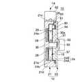
未使用検知紙収納部24は、ガス検知用テープ16の幅よりも十分に深く形成されることにより、乾燥剤28(図3)を収納する第1の収納空間24Aと、未使用のガス検知用テープ16を収納する第2の収納空間24Bとで構成されている。乾燥剤28は、第1の収納空間24Aに収納され、多孔板からなる仕切板29によって収納部24の奥壁24aに固定されている。乾燥剤28は、大気中の湿気を吸収することにより、未使用のガス検知紙11が湿気を帯びて退色するのを防止する。乾燥剤28としては、例えばシリカゲル、塩化カルシウム、高分子吸水ポリマー等が用いられる。 The unused detection
また、乾燥剤28の代わりに、または乾燥剤28に加えて脱酸素剤を第1の収納空間24Aに収納してもよい。脱酸素剤は、鉄、有機物など自身が酸化されて周囲の酸素を消費する薬剤を含むもので、大気中の酸素を可及的吸収し、長期保管において酸素によるガス検知紙11の退色を防止する。脱酸素剤としては、例えばエージレス(三菱ガス化学社製の商品名)が用いられる。 Further, instead of the
また、未使用検知紙収納部24の奥壁24aの中央には、第1の収納空間24Aの深さと略等しい突出高さの軸取付部30(図3)が一体に突設されている。さらに、軸取付部30の先端面には軸31が一体に突設されており、この軸31にはガス検知用テープ16の巻き芯17が回転自在に嵌装されている。軸31は、直径が軸取付部30の外径および巻き芯17の穴径より小さく設定されている。軸取付部30の先端面外周部、すなわち軸31より外側の環状部分は、巻き芯17の側面を受け止める受け面30aを形成している。この受け面30aは、巻き芯17を受け止めて係止することにより、ガス検知用テープ16の第1の収納空間24A方向への移動を阻止し仕切板29に接触するのを防止している。なお、軸31の先端は、未使用検知紙収納部24よりカセット本体21の後方に若干突出している。 In addition, a shaft mounting portion 30 (FIG. 3) having a protruding height substantially equal to the depth of the
第2の収納空間24Bは、ガス検知用テープ16を未使用検知紙収納部24内に収納したとき、後述するOリング80との接触を避けるために、図3に示すようにガス検知用テープ16の幅より十分に深く形成されている。このため、ガス検知用テープ16は、第2の収納空間24Bに収納されると未使用検知紙収納部24の開口部より内側に位置している。そして、未使用検知紙収納部24の内周壁24bには、ガス検知用テープ16を検知紙用通路26に導くスリット状の開口部40(図1、図2)が形成されている。この開口部40は、内周壁24bの最上位置からカセット本体21の中央側に所要角度ずれた位置に形成されている。 The
使用済み検知紙収納部25は、ガス検知用テープ16の幅と略等しい深さを有する円形の凹部からなり、奥壁25aの中央には使用済みのガス検知用テープ16を巻取る回転自在な巻取り軸36(回転部材)が設けられている。巻取り軸36には、未使用検知紙収納部24から繰り出され検知紙用通路26を通って使用済み検知紙収納部25に導かれたガス検知用テープ16の始端が止着されている。巻取り軸36の先端部は、カセット本体21の後方に突出し、先端面には後述する駆動モータ55の出力軸57が係合する係合凹部37が形成されている。また、使用済み検知紙収納部25の内周壁25bには、検知紙用通路26の終端が連通する開口部41が形成されている。この開口部41は、内周壁25の最上位置からカセット本体21の中央側に所要角度ずれた位置に形成されている。 The used detection
検知紙用通路26は、カセット本体21の背面上部に略水平に形成された溝状の水平通路部26aと、この水平通路部26aの上流側と下流側端にそれぞれ連設された下方に緩やかに湾曲するテープ導入部26bおよびテープ排出部26cとで構成されている。テープ導入部26bの始端は未使用検知紙収納部24の開口部40に連通し、テープ排出部26cの終端は使用済み検知紙収納部25の開口部41に連通している。水平通路部26aは、水平な上流側通路部分26a−1と下流側通路部分26a−2とで構成されている。水平通路部26aの下流側通路部分26a−2は、カセット本体21の上面S3 に設けた開口部42によって上方に開放することにより、ガス検知用テープ16をカセット本体21の外方に露呈させる曝露部43を形成している。The
曝露部43は、カセット本体21の長手方向に長い適宜長さと、ガス検知用テープ16の幅と略等しい幅とを有し、一側がカセット本体21の背面S2 に開放している。凹陥部32は、カセット本体21の背面S2 で検知紙用通路26に対応する部分に形成され、その周囲を取り囲んでいる。The exposed
カバープレート22は、カセット本体21と同一の大きさの長方形に形成され、ねじ孔27にねじ込まれる4本の止めねじ23によってカセット本体21の背面S2 に固定されることにより、未使用検知紙収納部24と使用済み検知紙収納部25の開放部と、検知紙用通路26の開放側面、すなわちカセット本体21の背面S2 に開放している通路側面と、凹陥部32を閉塞している。カバープレート22には、軸31と巻取り軸36を回転自在に支承する軸受部50、51がそれぞれ形成されている。一方の軸受部50は、図3に示すようにカバープレート22の裏面に形成した円形の凹部で構成されている。他方の軸受部51は、図1に示すようにカバープレート22を貫通する貫通孔で構成されている。The
検知紙巻取り手段13は、巻取り軸36と、この巻取り軸36を駆動する手段としての駆動モータ55とを備え、テープ巻取り時に駆動モータ55の駆動によりガス検知用テープ16を間欠的に一定長さ送って巻取るように構成されている。駆動モータ55は、カバープレート22の表面に位置決めされて複数本の止めねじ56により固定されており、計測室の制御部からの駆動信号によって駆動されるように構成されている。駆動モータ55の出力軸57は、先端が巻取り軸36の係合凹部37に係合しており、これにより出力軸57の回転を巻取り軸36に伝達している。 The detection paper take-up means 13 includes a take-up
オゾン濃度を測定するガス濃度測定手段14としては、反射率測定器61が用いられる。反射率測定器61は、カセット本体21の上面S3 に曝露部43の上方に位置するように2本の止めねじ60によって固定された筒体62と、この筒体62内に配設されたセンサ63と、信号処理回路等で構成されている。筒体62は、上下に開放する角形の筒体に形成されている。センサ63としては、波長が例えば、610nmの発光ダイオード63aとフォトダイオード63bが用いられる。発光ダイオード63aから出た光は、曝露部43に露呈しているガス検知紙11の表面に当たって反射するとフォトダイオード63bによって受光され、電気信号に変換された後、A/D変換により反射強度が数値化される。この数値は、色と対応していることからオゾン濃度を求めることができる。As the gas concentration measuring means 14 for measuring the ozone concentration, a
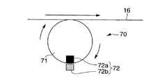
図1、図2、図5Aおよび図5Bにおいて、さらに、検知紙用通路26には、ガス検知用テープ16の送り量を検出する検知紙送り量検出手段70が配設されている。この検知紙送り量検出手段70は、検知紙用通路26の水平通路部26aで曝露部43より上流側の通路部分26a−1に設けられた回転体71と、この回転体71の回転を検出するセンサ72とで構成されている。回転体71は、上側外周面がガス検知用テープ16の下面に接触することにより、ガス検知用テープ16の走行時にガス検知用テープ16との摩擦によって回転するように構成されている。 1, 2, 5 </ b> A, and 5 </ b> B, a detection paper feed
センサ72は、回転体71の外周縁に固着された可動電極72aと、カセット本体21に固定され可動電極72aが摺接する固定電極72bとで構成されている。可動電極72aは、回転体71が1回転すると固定電極72bに接触し、これにより検知紙送り量検出手段70の回路が閉じて回転体71の回転が検出される。検知紙送り量検出手段70の検知信号は、計測室の制御部に送られる。制御部は、この検知信号に基づいて駆動モータ55を制御する。なお、可動電極72aまたは固定電極72bを複数個用い、回転体71が電極の数分の1回転する毎に回転を検出するようにしてもよい。 The
また、回転体71は、ガス検知用テープ16を上流側通路部分26a−1の上側壁面に軽く押し付けることにより、ガス検知紙11と上側壁面との隙間をシールしている。 The rotating
このようなオゾンガス濃度測定器10において、特に重要なことは、カセット12内に収納されている測定前の未使用のガス検知紙11がオゾンガスや湿気によって退色するのを防止することである。このため、未使用検知紙収納部24と、検知紙用通路26の曝露部43より上流側通路部分26a−1は、気密にシールされている。以下、そのシール構造について説明する。なお、酸素や湿気による退色は、前述したとおり乾燥剤28や脱酸素剤28によっても防止している。 In such an ozone gas
カバープレート22は、シール部材としてのOリング80を介してカセット本体21の背面S2 に固定されている。Oリング80は、カセット本体21の背面S2 で未使用検知紙収納部24の周囲に全周にわたって形成した環状のシール溝81に装着され、カバープレート22が密接されることにより、未使用検知紙収納部24の周囲を気密にシールし、カセット本体21とカバープレート22との隙間から外気が未使用検知紙収納部24内に侵入するのを防止している。シール溝81は、未使用検知紙収納部24の開口部40によって分断されてはいるが、Oリング80は分断されていない。The
また、水平通路部26aの上流側通路部分26a−1には、ガス検知用テープ16を当該通路部の上側壁面に押し付けてガス検知紙11と上側壁面との隙間をシールするシール手段85が、検知紙送り量検出手段70より上流側に位置して配設されている。 The
シール手段85は、上流側通路部分26a−1の下側壁面に設けた凹部86内に配設された上下動自在な押圧子85aと、この押圧子85aを上方に付勢するばね、スポンジ等の軟弾性部材85bとで構成され、これによってガス検知用テープ16を上流側通路部分26a−1の上側壁面にガス検知用テープ16の走行に大きな負荷とならない範囲内で軽く押し付けている。 The sealing means 85 includes a vertically
水平通路部26aの下流側通路部分26a−2には、当該通路部分の下側壁面より上方に突出しガス検知用テープ16を下から支持する水平な台座部90が同通路部分の全長にわたって突設されている。これにより、上流側通路部分26a−1の曝露部43に開放する後方側開口部の開口面積を狭くし、曝露部43からの上流側通路部分26a−1内への大気や湿気の侵入を極力防止するようにしている。 On the
さらに、検知紙用通路26のカセット本体21の背面S2 側に開放する開放側面については、カセット本体21とカバープレート22の接合面間に設けたシール部96によってシールしている。このシール部96は、カセット本体21の背面S2 で検知紙用通路26に対応する部分に形成した凹陥部32と、カバープレート22の裏面に突設され凹陥部32に嵌合する突起部95とで構成されている。突起部95は、凹陥部32との隙間を極力塞ぎシール性能を高めるために表面がゴム等によって被覆されている。突起部95には、カセット本体21の曝露部43に挿入される突出部分95aが一体に突設されている。この突出部95aは、通路部分26a−2と開口部42の幅をガス検知紙16の幅と略等しく設定するとともに、ガス検知用テープ16の一側縁を案内する案内面を形成し、ガス検知用テープ16の幅方向への移動を防止している。さらに、カバープレート22の裏面には、未使用検知紙収納部24に嵌挿されることにより、ガス検知用テープ16の幅方向の移動を規制する円板状の突起部97が突設されている。Further, the open side surface of the
次に、上記構造からなるオゾンガス濃度測定器10によるオゾンガスの測定について説明する。
測定に際しては、空気中にオゾンガスが存在する測定環境下において、計測室の制御部が駆動信号を送出し、駆動モータ55を駆動する。駆動モータ55は、制御部からの駆動信号によって駆動すると、ガス検知用テープ16を巻取り軸36に一定量巻取ってガス検知紙11の未使用部分を曝露部43に位置させる。ガス検知用テープ16が走行すると、この走行を検知紙送り量検出手段70が回転体71の回転数として検出し、その検知信号を制御部に送る。制御部は、検知紙送り量検出手段70からの検知信号により回転体71が所定の回転数回転したことを検出すると、駆動モータ55のスイッチをOFFにし、駆動モータ55を停止させる。これによりガス検知紙11の曝露されていない未使用部分は、曝露部43および筒体62を介してカセット12の外部に露呈して測定部分となり、この状態でオゾンガスの測定が開始される。Next, measurement of ozone gas by the ozone gas
In the measurement, the control unit of the measurement chamber sends a drive signal to drive the
オゾン濃度測定器10によって測定を開始すると、ガス検知紙11の曝露部43に臨んでいる測定部分11aは空気中に含まれているオゾンガスによって曝露されることにより徐々に変色(退色)する。ガス濃度検出手段14は、反射率測定器61のセンサ63(63a、63b)によって測定部分11aの変色を反射率の変化として一定時間毎に検出する。すなわち、発光ダイオード63aから出た光は、測定部分11aに当たるとその変色の度合いによって反射する光量が変化する。そして、測定部分11aに当たって反射した反射光は、フォトダイオード63bによって受光される。フォトダイオード63bは、変色部に当たって反射した反射光を受光すると電気信号に変換し、信号処理回路によってA/D変換し反射率を数値化する。この反射率を予め基準のガス検知紙をオゾンガスに曝露させて測定した反射率データと比較することにより、オゾン濃度が自動的に測定される。 When measurement is started by the ozone
一定時間経過して測定が終了した後、引き続き測定するときは、上記と同様に駆動モータ55を遠隔操作によって駆動してガス検知用テープ16を巻取り軸36に一定量巻取り、ガス検知紙11の曝露されていない未使用部分を曝露部43に位置させることにより、連続的に測定することができる。 When measurement is to be continued after a certain period of time has elapsed, the
このように本発明に係るオゾン濃度測定器10は、ロール状に巻回されたガス検知紙11を各種のシール手段およびシール構造によって気密にシールしたカセット12内に収納しているので、未使用のガス検知紙11が大気に晒されるおそれがなく保管が容易で、アルミニウムの包装袋に収納したりする必要がなく、長期保管に対しても十分に耐え得、オゾンガスによる変色、湿気による測定誤差、感度の低下等を防止することができる。また、ガス検知紙11を自動的に巻取る検知紙巻取り手段13を備えているので、連続的に測定することができ、図14に示した従来のオゾン濃度測定器1に比べて取り扱いが容易である。 As described above, the ozone
また、特に、未使用検知紙収納部24に、乾燥剤28や脱酸素剤を収納しているので、大気や湿気による影響を一層防止することができる。 In particular, since the
また、検知紙送り量検出手段70によって回転体71の回転を検出し、駆動モータ55のスイッチをON、OFF制御するようにしているので、巻取り軸36に巻取られるガス検知用テープ16の半径が徐々に増大しても、未使用のガス検知紙11を曝露部43に常に一定長さだけ送り出すことができる。したがって、テープ外周が一定の線速度になるように計算して駆動モータの回転数を制御したりする必要がなく、安価に製作することができる。なお、検知紙送り量検出手段70のセンサ72としては、接触タイプのものに限らず光学的に検出する非接触タイプのものであってもよい。 Further, since the rotation of the
さらに、全てのガス検知紙11を使い切った後は、カセット12から取り出して未使用の新しいガス検知用テープと交換すればよいので、カセット12を何度でも再利用することができる。 Furthermore, after all the
[第2の実施例]
図6において、本実施例は、ガス濃度測定手段14の筒体62内に検知紙送り量検出手段を兼ねたローラ88を設け、ガス検知用テープ16を台座部90に押し付けるようにしたものである。その他の構造は上記した第1の実施例と全く同一であるため、同一構成部材、部分には同一符号をもって示し、その説明を省略する。[Second Embodiment]
In FIG. 6, in this embodiment, a
また、本実施例においては、筒体62に検知紙送り量検出手段70を組み込めばよいので、外付けタイプとすることができ、カセット本体21内に検知紙送り量検出手段70のための配線を施す必要がない。このため、本実施例においては、上流側通路部分26a−1内の回転体71を単にガス検知用テープ16を通路壁に押し付けるシール部材として用いたり、または完全に取り除いてもよい。 In this embodiment, the detection paper feed amount detection means 70 may be incorporated into the
[第3の実施例]
図7および図8において、本実施例によるオゾン濃度測定器10Aは、請求項9に記載の測定器を示すもので、上記した第1の実施例におけるオゾン濃度測定器10に検知紙用通路26の水平通路部26aで曝露部43より上流側の通路部分に、ガス検知紙11の次期測定部分11bを予め外部に一定時間露呈させて測定環境の湿気になじませる前処理部100と、この前処理部100を大気に選択的に開放するシャッター101をさらに設けている。なお、図1〜図5に示した構成部品、部分と同一構成部材、部分については、同一符号をもって示し、その説明を適宜省略する。[Third embodiment]
7 and 8, an ozone
検知紙用通路26の水平通路部26aは、上流側通路部分26a−1と、前処理部100を形成する中間通路部分26a−2および曝露部43を形成する下流側通路部分26a−3とで構成されている。上流側通路部分26a−1は、カセット本体21の上面S3 に開放しておらず、検知紙送り量検出手段70とシール手段85が配設されている。The
前処理部100は、カセット本体21の上面S3 に形成された開口部100aを有し、この開口部100aが通常シャッター101によって閉塞されている。また、前処理部100は、曝露部43と略同じ大きさで、上板部21cの仕切壁102によって曝露部43と仕切られている。ガス検知用テープ16は、仕切壁102の下を通って曝露部43に搬送される。The
シャッター101は、細長い板状に形成されてカセット本体21の上面S3 に前後方向にスライド自在に配設されており、通常は前処理部100の開口部100aを気密に閉塞している。シャッター101の前端部上面には、指の爪を引っ掛ける引掛け部101aが形成されている。The
オゾン濃度を測定するガス濃度測定手段14の反射率測定器14は、カセット本体21の上面S3 に固着され曝露部43と前処理部100とシャッター101を覆うケース62と、このケース62内に配設されたセンサ63と、信号処理回路等で構成されている。ケース62は、上下に開放する細長い角筒体に形成され、内部が仕切板64によって前後2つの室65a、65bに仕切られており、前方側の室65aが前処理部100に連通し、後方側の室65bが曝露部43に連通している。仕切板64は、下端がカセット本体21の仕切壁102に当接している。また、ケース62の前面の下端には、シャッター101をガイドする左右一対のガイド部66が前方に向かって一体に延設されている。The
シャッター101は、ケース62の前方側の室65a内に位置し、前処理部100の開口部100aを閉塞した状態において前端部がケース62の前方に突出してガイド部66間に位置し、後端が仕切板64に当接している。 The
水平通路部26aの中間通路部分26a−2と下流側通路部分26a−3の境部には、仕切壁102の真下に位置しガス検知用テープ16を仕切壁102の下面に押し付ける押圧手段104が配設されている。この押圧手段104は、回転体105と、この回転体105を上方に付勢しガス検知用テープ16の下面に押し付ける図示を省略したばね等の弾性部材とで構成され、これによって仕切壁102とガス検知用テープ16との隙間をシールしている。 At the boundary between the
中間通路部分26a−2と下流側通路部分26a−3には、当該通路部分の下側壁面より上方に突出する水平な台座部90a、90bがそれぞれ設けられている。上流側の台座部90aは、上流側通路部分26a−1の下流側開口面積を狭くし、前処理部100から上流側通路部分26a−1への空気や湿気の侵入を極力防止している。下流側の台座部90bは、中間通路部分26a−2の上流側開口面積を狭くし、曝露部43から中間通路部分26a−2への空気や湿気の侵入を極力防止している。また、シャッター101は、前処理部100から中間通路部分26a−2への空気や湿気の侵入を防止している。 The
さらに、カセット本体21とカバープレート22の接合面には、シール部96が設けられている。このシール部96は、カセット本体21の背面S2 で検知紙用通路26に対応する部分に形成された凹陥部32と、カバープレート22の裏面に突設され凹陥部32に嵌合する突起部95とで構成されている。突起部95は、凹陥部32との隙間を塞ぎシール性能を高めるために表面がゴム等によって被覆されており、前処理部100と曝露部43にそれぞれ嵌合する突出部分95a、95bを一体に有し、これらによって前処理部100および曝露部43の幅をガス検知用テープ16の幅と略等しく設定するとともに、ガス検知用テープ16の一側縁を案内する案内面を形成し、テープ16の幅方向への移動を防止している。なお、その他の構造は、上記した第1の実施例と同一である。Further, a
上記構造からなるオゾンガス濃度測定器10Aによるオゾンガスの測定に際しては、大気中にオゾンガスが存在する測定環境下において、制御部からの駆動信号によって駆動モータ55を駆動してガス検知用テープ16を巻取り軸36に一定量巻取ってガス検知紙11の未使用の測定部分11aを曝露部43に位置させる。ガス検知紙11の測定部分11aを曝露部43に移動させると、次期測定部分11bは、前処理部100に移動して待機する。前処理部100は、シャッター101によって閉塞されている。 When measuring ozone gas with the ozone gas
測定に際しては、駆動モータ55の駆動によってガス検知用テープ16を走行させ、ガス検知紙11の測定部分11aを曝露部43に移動、停止させると、この状態でオゾンガスの測定が開始される。 In measurement, when the
オゾンガスの測定を開始すると、曝露部43に臨んでいるガス検知紙11の測定部分11aは、大気中に含まれているオゾンガスによって曝露されることにより徐々に変色(退色)する。ガス濃度検出手段14は、センサ63によりガス検知紙11の変色を反射率の変化として一定時間毎に検出し、この反射率を予め基準のガス検知紙をオゾンガスに曝露させて測定した反射率と比較することにより、オゾン濃度を自動的に測定する。 When measurement of ozone gas is started, the
ガス検知紙11の測定部分11aによるオゾンガスの測定中において、次期測定部分11bは、前処理部100内にあって、前処理、すなわち測定環境の湿気になじまされる。この次期測定部分11bの前処理は、測定部分11aによる測定が終了する一定時間前、例えば30分前にシャッター101を作業者が手で開くかあるいはモータを用いて自動的に開き、前処理部100を一定時間開放することにより行われる。前処理の最適時間は、30分程度で、これより長いと大気中のオゾンガスによって必要以上に変色するため好ましくない。また、短すぎると、大気中の湿気の吸い込みが不十分で、大気の湿気に合った反射率とならず、測定誤差となるため好ましくない。前処理が終了すると、シャッター101を閉じて測定部分11aによる測定が終了するまで、次期測定部分11bを前処理部100内に待機させておく。 During the measurement of ozone gas by the
一定時間経過して測定部分11aによる測定が終了すると、駆動モータ55を遠隔操作によって駆動してガス検知用テープ16を巻取り軸36に一定量巻取り、ガス検知紙11の次期測定部分11bを曝露部43に移動させて新たな測定部分とする。ここで、前処理の済んだ次期測定部分11bの反射率の初期値を予め測定しておき、測定中はこの反射率の初期値との差を求めることで前処理中にオゾンに曝露した分が測定誤差とならないように連続測定することができる。一方、連続して測定しないときは、次の測定を開始するまで測定が終わった測定部分11aを曝露部43内に滞留させておく。 When the measurement by the
また、連続して測定しない場合は、測定部分11aによる測定中においてシャッター101を閉じたままの状態に保持し、前処理部100内に待機している次期測定部分11bの前処理を保留しておく。 If measurement is not performed continuously, the
このように本実施例によるオゾン濃度測定器10Aは、曝露部43の上流側に前処理部100を設け、ガス検知紙11の次期測定部分11bを待機させておき、次に測定を開始する前にシャッター101を開いて前処理部100を大気に開放することにより、次期測定部分11bを予め測定環境の湿気に一定時間なじませるようにしたので、次期測定部分11bを曝露部43に移動させて測定を開始したときの反射率を外気の湿度に合った反射率とすることができる。したがって、測定部分11aによる測定が終了した後、待ち時間を設ける必要がなく、次期測定部分11bによる連続測定を行うことができる。また、湿度による測定誤差が少なく、測定精度を向上させることができる。 As described above, the ozone
[第4の実施例]
図9において、本実施例は、図7に示したスライド型のシャッター101の代わりにカセット12の背面側に、回転型のシャッター101Aを配設したものである。カバープレート22は、前処理部100に連通する連通孔110を有している。シャッター101Aは、円板状に形成されてカバープレート22の連通孔110に連通可能な通気孔112を有し、カバープレート22の表面に突設した回転軸113に回転自在に配設されている。シャッター101Aは、通常連通孔110を閉塞しており、一定角度回動して通気孔112を連通孔110に一致させることにより、前処理部100を大気に開放させるように構成されている。このため、カセット本体21は、上面S3 に曝露部43のみが開放し、前処理部100は開放されておらず、また図7に示したスライド自在なシャッター101が配設されていない。その他の構造は、上記した第3の実施例と同様である。[Fourth embodiment]
9, in this embodiment, a
このような構造においても、シャッター101Aを回転させて通気孔112を連通孔110に連通させると、前処理部100を大気に開放させることができるので、上記した第3の実施例と同様にガス検知紙11の前処理部100に待機している次期測定部分11bを前処理して測定環境の湿気になじませることができる。なお、シャッター101A(シャッター101も同様)は、手動操作されるものに限らず、モータ駆動によって動作されるものであってもよい。 Even in such a structure, if the
[第5の実施例]
図10および図11において、本実施例におけるオゾン濃度測定器10Bは、請求項14に記載の測定器を示すもので、上記した第1の実施例におけるオゾン濃度測定器10に検知紙用通路26水平通路部26aで曝露部43より上流側の通路部分に、ガス検知紙11の次期測定部分11bを予め外部に一定時間露呈させて測定環境の湿気になじませる前処理部100と、この前処理部100の開口部121a、121bを覆いオゾンガスを除去し湿気を通過させるフィルター120a、120bをさらに設けている点で、上記した第1の実施例におけるオゾン濃度測定器10と異なっている。また、第4の実施例で示したオゾン濃度測定器10Aとは、シャッター101または101Aの代わりにフィルター120a〜120cを設けた点で異なっている。なお、図1〜図5、図7〜図9に示した構成部品、部分と同一構成部材、部分については、同一符号をもって示し、その説明を適宜省略する。[Fifth embodiment]
10 and 11, an ozone
検知紙用通路26の水平通路部26aは、上流側通路部分26a−1と、中間通路部分26a−2および下流側通路部分26a−3とで構成されている。上流側通路部分26a−1と、前処理部100を形成する中間通路部分26a−2は、カセット本体21の上側に開放しておらず、曝露部43を形成する下流側通路部分26a−3のみが上方に開放している。 The
前処理部100は、通風のためにカセット本体21の前面S1 および背面S2 に形成した開口部121a(なお、背面に開口する開口部は中間通路部分26a−2のカバープレート側の開放側縁である)と、カバープレート22に形成した開口部121bとによってカセット12の前後面に開放している。また、これらの開口部121a、121bは、通気性は有するが測定ガスであるオゾンガスを除去するフィルター120a、120bによってそれぞれ覆われている。このため、前処理部100は、測定環境と同じ湿度をもつ状態に保持されている。Preprocessing
フィルター120a、120bとしては、従来公知のオゾンフィルター(特開平3−213145号公報、特公昭63−31258号公報、特開平4−7038号公報等)またはメンブレンフィルター(特開2006−258533号公報)が用いられる。ここでは、薄いアルミ箔によるコルゲートハニカム構造体を担体とし、その表面に金属(Mn)系触媒をコーティングしたオゾンフィルターを用いた例を示している。 As the
メンブレンフィルターとしては、例えば宇部興産社製のポリイミドフィルム”ユーピレックスS”(商標名)が用いられる。オゾンガスは、物質の表面で吸収され易いため、メンブレンフィルターにも一定の割合で吸収されることが知られている。 As the membrane filter, for example, a polyimide film “Upilex S” (trade name) manufactured by Ube Industries, Ltd. is used. Since ozone gas is easily absorbed on the surface of a substance, it is known that ozone gas is also absorbed at a certain rate by the membrane filter.
カセット本体21の背面S2 とカバープレート22との接合面間に設けられているシール部96は、カセット本体21の背面上部で検知紙用通路26に対応する部分に形成された凹陥部32と、カバープレート22の裏面に突設され凹陥部32に嵌合する突起部95とで構成されている。凹陥部32は、前端が未使用検知紙収納部24の開口部40の上方に延在し、後端が使用済み検知紙収納部25の開口部41の上方に延在する長さを有するが、中間部が垂直な仕切板124によって仕切られることにより前後2つの室32a、32bで構成されている。前側の室32aは上流側通路部分26a−1の下方に位置し、後側の室32bは前処理部100と曝露部43の下方に位置している。また、後側の室32bの前端には、オゾンフィルター120a、120bだけでは厚さ(長さ)が不十分な場合、追加のオゾンフィルター120cを収納するためのフィルター用収納凹部125が設けられている。このフィルター用収納部125は、下方に向かって延設されることによりカセット本体21の底面S4 に開放する開口部121cを有し、これによってオゾンフィルター120cの下端(外気導入用の吸気口)をカセット本体21の外部に露呈させている。A
カバープレート22の突起部95は、前側の室32aと後側の室32bに対応一致するように前後2つに分割された前側凸部95Aと後側凸部95Bとで構成されている。また、前側凸部95Aと後側凸部95Bは、前側の室32aと後側の室32bとの隙間を塞ぎシール性能を高めるために表面がゴム等によってそれぞれ被覆されている。さらに、後側凸部95Bには、曝露部43に嵌合する突出部分95aが一体に突設されている。 The
このような構造からなるオゾン濃度測定器10Bにおいても、前処理部100を開口部121a〜121cによって外部に開放し、オゾンフィルター120a〜120cによって通気性を確保しているので、前処理部100を測定環境と同じ湿度状態に保持することができる。このため、前処理部100内に待機しているガス検知紙11の次期測定部分11bは、測定環境の湿気になじみ、反射率を外気の湿度に合った反射率とすることができる。一方、オゾンフィルター120a〜120cは、大気中のオゾンガスを除去するので、オゾンガスが前処理部100に侵入して次期測定部分11bを曝露することはない。したがって、ガス検知紙11の測定部分11aによる測定が終了した後、前処理部100内に待機しているガス検知紙11の次期測定部分11bを曝露部43に移動させると、上記した第3の実施例と同様に待ち時間を設ける必要がなく、オゾンガスの測定を連続して行うことができる。また、前処理によって次期測定部分11bの反射率が外気の湿度に合った反射率になれば、湿度依存性を有するガス検知紙11であっても、湿度による測定誤差が生じず、測定精度を向上させることができる。 Also in the ozone
また、未使用検知紙収納部24と、前処理部100より上流側の通路部分26a−1、テープ導入部26bおよび未使用検知紙収納部24には、オゾンガスが侵入するおそれがなく、ガス検知紙11の未使用部分がオゾンガスによって曝露されるのを確実に防止することができる。 Further, there is no possibility that ozone gas enters the unused detection
[第6の実施例]
図13において、本実施例におけるオゾン濃度測定器は、カセット12の前後面に開口部を設ける代わりに、カセット本体21の上面S3 に前処理部100の開口部100aを形成し、この開口部100aをオゾンフィルター120によって覆ったものである。なお、その他の構造は上記した第5の実施例と略同一であるため、同一構成部材、部分には同一符号をもって示し、その説明を省略する。[Sixth embodiment]
In FIG. 13, the ozone concentration measuring apparatus according to the present embodiment forms an
このような構造においも、オゾンフィルター120によって前処理部100の通気性を確保するようにしているので、前処理部100内に待機しているガス検知紙11の次期測定部分11bを大気中のオゾンガスに曝露させることなく測定環境の湿気になじませることができる。 Even in such a structure, the
なお、本発明は上記した実施例に何ら限定されるものではなく、種々の変形、変更が可能である。例えば、上記した実施例においては、いずれもオゾンガスに反応する色素としてインジゴカルミンを用いたが、これに限らずトリフェニルメタン色素やアゾ色素、アントラキン色素等を用いてもよい。 The present invention is not limited to the above-described embodiments, and various modifications and changes can be made. For example, in the above-described embodiments, indigo carmine is used as a dye that reacts with ozone gas, but not limited thereto, a triphenylmethane dye, an azo dye, an anthraquin dye, or the like may be used.
また、上記した実施例においては、駆動モータ55の遠隔操作によってガス検知用テープ16を巻き上げ、ガス検知紙11の変色を反射率測定装置61によって測定するようにした例を示したが、本発明はこれに何ら特定されるものではなく、携帯型の測定器としても使用することができる。その場合は、駆動モータ55の代わりに手動操作されるハンドルを巻取り軸36の先端に取付け、図14に示した色見本5をカセット12の上面適宜箇所に貼り付けておき、ガス検知紙11の変色をこの色見本5と比較してガス濃度を測定するようにすればよい。また、携帯型の場合はガス濃度測定手段14や検知紙送り量検出手段70も必要としないため、一層簡素化することができる。 In the above-described embodiment, the
本発明に係るガス濃度測定器は、オゾンを測定するオゾン濃度測定器に限らず、二酸化窒素ガスの濃度測定器にも適用することが可能である。その場合は、検知剤として二酸化窒素ガス(NO2 )に反応するジアゾ化試薬およびカップリング試薬の混合物等を多孔体に含浸させたガス検知素子を用いればよい。The gas concentration measuring device according to the present invention is not limited to an ozone concentration measuring device that measures ozone, but can also be applied to a concentration measuring device for nitrogen dioxide gas. In that case, a gas detection element in which a porous body is impregnated with a mixture of a diazotization reagent that reacts with nitrogen dioxide gas (NO2 ) and a coupling reagent or the like may be used as a detection agent.
Claims (10)
Translated fromJapaneseロール状に巻回されて前記カセット内に収納され特定ガスに反応すると変色するテープ状のガス検知紙と、
前記ガス検知紙を巻取る検知紙巻取り手段と、
を具備し、
前記カセットは、
前記カセット本体の前記背面に形成された未使用の前記ガス検知紙を収納する未使用検知紙収納部と、
使用済みの前記ガス検知紙を収納する使用済み検知紙収納部と、
前記未使用検知紙収納部と前記使用済み検知紙収納部を接続する検知紙用通路と、
前記カセット本体の上面に形成され前記検知紙用通路の一部が前記カセットの外部に露呈する曝露部と、
前記カセット本体と前記カバープレートとの接合面間に介在され前記未使用検知紙収納部の周囲を気密にシールするシール部材と、
前記検知紙用通路の前記曝露部より上流側の通路部分に設けられ前記ガス検知紙を前記上流側通路部分の壁面に押し付けるシール手段と、
を有し、
前記検知紙用通路の曝露部より上流側の通路部分に、ガス検知紙の次期測定部分を予め測定環境の湿気になじませる前処理部と、前記前処理部を大気に選択的に開放するシャッターをさらに設けたことを特徴とするガス濃度測定器。A cassette having a cassette body and a cover plate covering a back surface of the cassette body;
A tape-like gas detection paper wound in a roll and stored in the cassette and discolored when reacting to a specific gas;
Detection paper winding means for winding the gas detection paper;
Comprising
The cassette is
An unused detection paper storage unit for storing the unused gas detection paper formed on the back surface of the cassette body;
A used detection paper storage section for storing the used gas detection paper;
A detection paper path connecting the unused detection paper storage unit and the used detection paper storage unit;
An exposed portion that is formed on the upper surface of the cassette body and a part of the passage for the detection paper is exposed to the outside of the cassette;
A seal member that is interposed between the joint surfaces of the cassette body and the cover plate and hermetically seals the periphery of the unused detection paper storage unit;
Sealing means provided in a passage portion upstream of the exposed portion of the detection paper passage and pressing the gas detection paper against a wall surface of the upstream passage portion;
I have a,
A pre-processing unit that preliminarily adjusts the next measurement portion of the gas detection paper to the humidity of the measurement environment, and a shutter that selectively opens the pre-processing unit to the atmosphere in the passage portion upstream of the exposure portion of the detection paper passage. A gas concentration measuring device further comprising:
前記前処理部は、カセット本体の上面に開放する開口部を有し、 The pretreatment unit has an opening that opens to the upper surface of the cassette body,
前記シャッターは、前記カセット本体の前記上面にスライド自在に設けられ、前記開口部を開閉することを特徴とするガス濃度測定器。 The gas concentration measuring device according to claim 1, wherein the shutter is slidably provided on the upper surface of the cassette body and opens and closes the opening.
カバープレートは、前処理部に連通する連通孔を有し、 The cover plate has a communication hole communicating with the pretreatment unit,
前記シャッターは、通気孔を有して前記カバープレートに回転自在に設けられ、前記連通孔と前記通気孔を介して前記前処理部を大気に開放することを特徴とするガス濃度測定器。 The gas concentration measuring instrument, wherein the shutter has a vent hole and is rotatably provided on the cover plate, and opens the pretreatment part to the atmosphere via the communication hole and the vent hole.
前記曝露部と前記前処理部との間に仕切壁を設けるとともに、この仕切壁の下面にガス検知紙を押し付ける押圧手段をさらに設けたことを特徴とするガス濃度測定器。 A gas concentration measuring instrument characterized in that a partition wall is provided between the exposed portion and the pretreatment portion, and further a pressing means for pressing the gas detection paper against the lower surface of the partition wall.
前記シャッターは、ガス検知紙の前処理部に待機している次期測定部分が測定のために曝露部に送られる一定時間前に動作することにより前記前処理部を大気に開放することを特徴とするガス濃度測定器。 The shutter opens the pretreatment unit to the atmosphere by operating a predetermined time before the next measurement unit waiting in the pretreatment unit of the gas detection paper is sent to the exposure unit for measurement. Gas concentration measuring instrument.
ロール状に巻回されて前記カセット内に収納され特定ガスに反応すると変色するテープ状のガス検知紙と、 A tape-like gas detection paper wound in a roll and stored in the cassette and discolored when reacting to a specific gas;
前記ガス検知紙を巻取る検知紙巻取り手段と、 Detection paper winding means for winding the gas detection paper;
を具備し、 Comprising
前記カセットは、 The cassette is
前記カセット本体の前記背面に形成された未使用の前記ガス検知紙を収納する未使用検知紙収納部と、 An unused detection paper storage unit for storing the unused gas detection paper formed on the back surface of the cassette body;
使用済みの前記ガス検知紙を収納する使用済み検知紙収納部と、 A used detection paper storage section for storing the used gas detection paper;
前記未使用検知紙収納部と前記使用済み検知紙収納部を接続する検知紙用通路と、 A detection paper path connecting the unused detection paper storage unit and the used detection paper storage unit;
前記カセット本体の上面に形成され前記検知紙用通路の一部が前記カセットの外部に露呈する曝露部と、 An exposed portion that is formed on the upper surface of the cassette body and a part of the passage for the detection paper is exposed to the outside of the cassette;
前記カセット本体と前記カバープレートとの接合面間に介在され前記未使用検知紙収納部の周囲を気密にシールするシール部材と、 A seal member that is interposed between the joint surfaces of the cassette body and the cover plate and hermetically seals the periphery of the unused detection paper storage unit;
前記検知紙用通路の前記曝露部より上流側の通路部分に設けられ前記ガス検知紙を前記上流側通路部分の壁面に押し付けるシール手段と、 Sealing means provided in a passage portion upstream of the exposed portion of the detection paper passage and pressing the gas detection paper against a wall surface of the upstream passage portion;
を有し、 Have
前記検知紙用通路の曝露部より上流側の通路部分にガス検知紙の次期測定部分を予め測定環境になじませる前処理部と、前記前処理部の開口部を覆い特定ガスを除去し湿気を通過させるフィルターをさらに設けたことを特徴とするガス濃度測定器。 A pre-processing unit that preliminarily adjusts the next measurement portion of the gas detection paper to the measurement environment upstream of the exposed portion of the detection paper passage, covers the opening of the pre-processing unit, removes specific gas, and removes moisture. A gas concentration measuring device, further comprising a filter for passing therethrough.
前記前処理部の開口部は、カセット本体の上面に開放していることを特徴とするガス濃度測定器。 The gas concentration measuring instrument according to claim 1, wherein the opening of the pretreatment section is open to the upper surface of the cassette body.
前記前処理部は、カセット本体の前面および背面に開放する開口部と、カバープレートに形成された開口部とによって外部に連通していることを特徴とするガス濃度測定器。 The gas concentration measuring instrument according to claim 1, wherein the pretreatment unit communicates with the outside through an opening that opens to a front surface and a back surface of the cassette body and an opening formed in the cover plate.
前記曝露部と前記前処理部との間に仕切壁を設けるとともに、この仕切壁の下面にガス検知紙を押し付ける押圧手段をさらに設けたことを特徴とするガス濃度測定器。 A gas concentration measuring instrument characterized in that a partition wall is provided between the exposed portion and the pretreatment portion, and further a pressing means for pressing the gas detection paper against the lower surface of the partition wall.
前記ガス検知紙によって検出される特定ガスがオゾンガスであり、 The specific gas detected by the gas detection paper is ozone gas,
前記フィルターが、オゾンガスを除去するオゾンフィルターとメンブレンフィルターのうちのいずれか一方であることを特徴とするガス濃度測定器。 The gas concentration measuring instrument, wherein the filter is one of an ozone filter for removing ozone gas and a membrane filter.
Priority Applications (1)
| Application Number | Priority Date | Filing Date | Title |
|---|---|---|---|
| JP2009501650AJP4809919B2 (en) | 2007-09-14 | 2008-09-03 | Gas concentration measuring instrument |
Applications Claiming Priority (8)
| Application Number | Priority Date | Filing Date | Title |
|---|---|---|---|
| JP2007239125 | 2007-09-14 | ||
| JP2007239105 | 2007-09-14 | ||
| JP2007239125 | 2007-09-14 | ||
| JP2007239108 | 2007-09-14 | ||
| JP2007239105 | 2007-09-14 | ||
| JP2007239108 | 2007-09-14 | ||
| JP2009501650AJP4809919B2 (en) | 2007-09-14 | 2008-09-03 | Gas concentration measuring instrument |
| PCT/JP2008/065880WO2009034897A1 (en) | 2007-09-14 | 2008-09-03 | Gas concentration measuring instrument |
Publications (2)
| Publication Number | Publication Date |
|---|---|
| JPWO2009034897A1 JPWO2009034897A1 (en) | 2010-12-24 |
| JP4809919B2true JP4809919B2 (en) | 2011-11-09 |
Family
ID=40451906
Family Applications (1)
| Application Number | Title | Priority Date | Filing Date |
|---|---|---|---|
| JP2009501650AExpired - Fee RelatedJP4809919B2 (en) | 2007-09-14 | 2008-09-03 | Gas concentration measuring instrument |
Country Status (2)
| Country | Link |
|---|---|
| JP (1) | JP4809919B2 (en) |
| WO (1) | WO2009034897A1 (en) |
Cited By (3)
| Publication number | Priority date | Publication date | Assignee | Title |
|---|---|---|---|---|
| KR20190132571A (en)* | 2014-10-01 | 2019-11-27 | 어드밴스드 폴리머 모니터링 테크놀로지스, 인크. | Systems and methods for control of polymer reactions and processing using automatic continuous online monitoring |
| KR102136342B1 (en)* | 2019-12-13 | 2020-07-22 | 국방과학연구소 | Apparatus for sampling gas, drone therewith and control method thereof |
| US11815439B2 (en) | 2019-12-13 | 2023-11-14 | Agency For Defense Development | Apparatus for sampling gas, drone therewith and control method thereof |
Families Citing this family (3)
| Publication number | Priority date | Publication date | Assignee | Title |
|---|---|---|---|---|
| CN110624123A (en)* | 2019-10-26 | 2019-12-31 | 河南极速环保有限公司 | Ozone disinfection result identification device, disinfection device with same and disinfection method |
| KR102148464B1 (en)* | 2019-12-13 | 2020-08-27 | 국방과학연구소 | Apparatus for detecting gas, drone therewith and control method thereof |
| CN119375434B (en)* | 2024-12-30 | 2025-05-27 | 福建万安华科电子科技有限公司 | Portable toxin agent alarm detector |
Family Cites Families (7)
| Publication number | Priority date | Publication date | Assignee | Title |
|---|---|---|---|---|
| JPH01105168A (en)* | 1987-10-17 | 1989-04-21 | Fuji Photo Film Co Ltd | Test film cassette for biochemical analysis |
| JP3381829B2 (en)* | 1997-06-05 | 2003-03-04 | 理研計器株式会社 | Color reaction tape type gas measurement device |
| JPH11223627A (en)* | 1998-02-04 | 1999-08-17 | Riken Keiki Co Ltd | Tape type gas measuring device |
| JP3485246B2 (en)* | 1998-10-01 | 2004-01-13 | 理研計器株式会社 | Oxidizing gas detection sheet |
| JP2001124759A (en)* | 1999-10-28 | 2001-05-11 | Toppan Printing Co Ltd | Gas detection indicator |
| AU2003296703A1 (en)* | 2002-12-23 | 2004-07-14 | F.Hoffmann-La Roche Ag | Transport device for transporting test strips in an analysis system |
| JP4485977B2 (en)* | 2005-03-16 | 2010-06-23 | 日本電信電話株式会社 | Case for ozone porous glass sensor |
- 2008
- 2008-09-03JPJP2009501650Apatent/JP4809919B2/ennot_activeExpired - Fee Related
- 2008-09-03WOPCT/JP2008/065880patent/WO2009034897A1/enactiveApplication Filing
Cited By (4)
| Publication number | Priority date | Publication date | Assignee | Title |
|---|---|---|---|---|
| KR20190132571A (en)* | 2014-10-01 | 2019-11-27 | 어드밴스드 폴리머 모니터링 테크놀로지스, 인크. | Systems and methods for control of polymer reactions and processing using automatic continuous online monitoring |
| KR102202990B1 (en)* | 2014-10-01 | 2021-01-13 | 어드밴스드 폴리머 모니터링 테크놀로지스, 인크. | Systems and methods for control of polymer reactions and processing using automatic continuous online monitoring |
| KR102136342B1 (en)* | 2019-12-13 | 2020-07-22 | 국방과학연구소 | Apparatus for sampling gas, drone therewith and control method thereof |
| US11815439B2 (en) | 2019-12-13 | 2023-11-14 | Agency For Defense Development | Apparatus for sampling gas, drone therewith and control method thereof |
Also Published As
| Publication number | Publication date |
|---|---|
| WO2009034897A1 (en) | 2009-03-19 |
| JPWO2009034897A1 (en) | 2010-12-24 |
Similar Documents
| Publication | Publication Date | Title |
|---|---|---|
| JP4809919B2 (en) | Gas concentration measuring instrument | |
| US9897588B2 (en) | Method for analyzing body fluids | |
| JP4988690B2 (en) | Ozone gas sensing element | |
| CA1250214A (en) | Method and apparatus for detection of certain nitrogen-containing gases using chemiluminescence | |
| JP2008107139A (en) | Gas concentration detection tape, gas concentration measuring device, gas concentration measuring device cartridge, and gas concentration measuring device case | |
| US20130214175A1 (en) | Optical sensor, especially for determining substance concentrations in aqueous solutions by means of a fluorescence measurement | |
| JP3206697B2 (en) | Acid gas detection paper | |
| US7981364B2 (en) | Gas detection method and system | |
| US20100208239A1 (en) | Chlorine dioxide sensor | |
| JP2007502997A (en) | Equipment for the continuous determination of substances | |
| JP2011085538A (en) | Gas sensor | |
| KR101041897B1 (en) | Gas detection material and suitable gas detection device | |
| JP2007298328A (en) | Photocatalyst activity evaluation device | |
| CN101548183A (en) | Gas concentration measuring instrument | |
| JP2008058058A (en) | Gas concentration measuring instrument | |
| EP2199789A1 (en) | Method and system for producing a gas-sensitive substrate | |
| JPH0755792A (en) | Formalin sensing tape | |
| EP3304048B1 (en) | Cartridge for receiving an analyte | |
| JP2008089395A (en) | Photocatalyst meter, light performance measuring method, and sensor head used therefor | |
| JP3051618B2 (en) | Dry analytical film supply device | |
| JP2008116386A (en) | Gas concentration measuring instrument | |
| JP2009244047A (en) | Sample for ph measurement, ph measurement apparatus and ph measurement method | |
| JP2006064517A (en) | Toluene-measuring device and toluene detection unit | |
| JP2005069761A (en) | Gas detection member | |
| CN212159559U (en) | Disinfectant quality on-site detection device |
Legal Events
| Date | Code | Title | Description |
|---|---|---|---|
| A131 | Notification of reasons for refusal | Free format text:JAPANESE INTERMEDIATE CODE: A131 Effective date:20110614 | |
| A521 | Request for written amendment filed | Free format text:JAPANESE INTERMEDIATE CODE: A523 Effective date:20110708 | |
| TRDD | Decision of grant or rejection written | ||
| A01 | Written decision to grant a patent or to grant a registration (utility model) | Free format text:JAPANESE INTERMEDIATE CODE: A01 Effective date:20110809 | |
| A01 | Written decision to grant a patent or to grant a registration (utility model) | Free format text:JAPANESE INTERMEDIATE CODE: A01 | |
| A61 | First payment of annual fees (during grant procedure) | Free format text:JAPANESE INTERMEDIATE CODE: A61 Effective date:20110819 | |
| FPAY | Renewal fee payment (event date is renewal date of database) | Free format text:PAYMENT UNTIL: 20140826 Year of fee payment:3 | |
| S531 | Written request for registration of change of domicile | Free format text:JAPANESE INTERMEDIATE CODE: R313531 | |
| R350 | Written notification of registration of transfer | Free format text:JAPANESE INTERMEDIATE CODE: R350 | |
| LAPS | Cancellation because of no payment of annual fees |