JP4809894B2 - Apparatus and method for controlling blood pressure using a reverse perfusion cannula - Google Patents
Apparatus and method for controlling blood pressure using a reverse perfusion cannulaDownload PDFInfo
- Publication number
- JP4809894B2 JP4809894B2JP2008524152AJP2008524152AJP4809894B2JP 4809894 B2JP4809894 B2JP 4809894B2JP 2008524152 AJP2008524152 AJP 2008524152AJP 2008524152 AJP2008524152 AJP 2008524152AJP 4809894 B2JP4809894 B2JP 4809894B2
- Authority
- JP
- Japan
- Prior art keywords
- region
- cannula
- proximal
- blood pressure
- distal end
- Prior art date
- Legal status (The legal status is an assumption and is not a legal conclusion. Google has not performed a legal analysis and makes no representation as to the accuracy of the status listed.)
- Expired - Fee Related
Links
- 230000036772blood pressureEffects0.000titleclaimsdescription9
- 238000000034methodMethods0.000titledescription32
- 230000010412perfusionEffects0.000titledescription25
- 230000002441reversible effectEffects0.000titledescription18
- 210000002216heartAnatomy0.000claimsdescription12
- 229910000861Mg alloyInorganic materials0.000claimsdescription9
- 210000004191axillary arteryAnatomy0.000claimsdescription8
- 210000002048axillary veinAnatomy0.000claimsdescription7
- 230000017531blood circulationEffects0.000claimsdescription7
- 208000031481Pathologic ConstrictionDiseases0.000claimsdescription6
- 210000003191femoral veinAnatomy0.000claimsdescription6
- 230000036262stenosisEffects0.000claimsdescription6
- 208000037804stenosisDiseases0.000claimsdescription6
- 210000001105femoral arteryAnatomy0.000claimsdescription5
- 210000001099axillaAnatomy0.000claimsdescription4
- 229920005862polyolPolymers0.000claimsdescription4
- 150000003077polyolsChemical class0.000claimsdescription4
- 206010020772HypertensionDiseases0.000claims3
- 208000001953HypotensionDiseases0.000claims3
- 208000012866low blood pressureDiseases0.000claims3
- 230000008081blood perfusionEffects0.000claims2
- 210000003748coronary sinusAnatomy0.000description27
- 210000003462veinAnatomy0.000description25
- 210000001367arteryAnatomy0.000description11
- 239000008280bloodSubstances0.000description10
- 210000004369bloodAnatomy0.000description10
- 206010029113NeovascularisationDiseases0.000description8
- 239000000463materialSubstances0.000description8
- FBPFZTCFMRRESA-KVTDHHQDSA-ND-MannitolChemical compoundOC[C@@H](O)[C@@H](O)[C@H](O)[C@H](O)COFBPFZTCFMRRESA-KVTDHHQDSA-N0.000description7
- 229930195725MannitolNatural products0.000description7
- 239000000594mannitolSubstances0.000description7
- 235000010355mannitolNutrition0.000description7
- 238000001356surgical procedureMethods0.000description5
- 201000001779Leukocyte adhesion deficiencyDiseases0.000description4
- 210000004351coronary vesselAnatomy0.000description4
- 230000008569processEffects0.000description4
- 206010019280Heart failuresDiseases0.000description3
- FYYHWMGAXLPEAU-UHFFFAOYSA-NMagnesiumChemical compound[Mg]FYYHWMGAXLPEAU-UHFFFAOYSA-N0.000description3
- 206010030113OedemaDiseases0.000description3
- 230000003872anastomosisEffects0.000description3
- 230000004872arterial blood pressureEffects0.000description3
- 230000003143atherosclerotic effectEffects0.000description3
- QVGXLLKOCUKJST-UHFFFAOYSA-Natomic oxygenChemical compound[O]QVGXLLKOCUKJST-UHFFFAOYSA-N0.000description3
- 238000009530blood pressure measurementMethods0.000description3
- 230000000302ischemic effectEffects0.000description3
- 238000002690local anesthesiaMethods0.000description3
- 229910052749magnesiumInorganic materials0.000description3
- 239000011777magnesiumSubstances0.000description3
- 238000005259measurementMethods0.000description3
- 210000004165myocardiumAnatomy0.000description3
- 239000001301oxygenSubstances0.000description3
- 229910052760oxygenInorganic materials0.000description3
- 210000005245right atriumAnatomy0.000description3
- 201000001320AtherosclerosisDiseases0.000description2
- 208000010496Heart ArrestDiseases0.000description2
- 206010040744Sinus headacheDiseases0.000description2
- 230000002785anti-thrombosisEffects0.000description2
- 238000010009beatingMethods0.000description2
- 230000008901benefitEffects0.000description2
- 230000000740bleeding effectEffects0.000description2
- 230000000747cardiac effectEffects0.000description2
- 150000001875compoundsChemical class0.000description2
- 238000002594fluoroscopyMethods0.000description2
- 230000006870functionEffects0.000description2
- 238000001727in vivoMethods0.000description2
- 238000003780insertionMethods0.000description2
- 230000037431insertionEffects0.000description2
- 210000005240left ventricleAnatomy0.000description2
- 238000012986modificationMethods0.000description2
- 230000004048modificationEffects0.000description2
- 238000012544monitoring processMethods0.000description2
- 210000000056organAnatomy0.000description2
- -1polyethylenePolymers0.000description2
- 108090000623proteins and genesProteins0.000description2
- 210000003270subclavian arteryAnatomy0.000description2
- 230000001360synchronised effectEffects0.000description2
- 210000000689upper legAnatomy0.000description2
- 230000002861ventricularEffects0.000description2
- BSYNRYMUTXBXSQ-FOQJRBATSA-N59096-14-9Chemical compoundCC(=O)OC1=CC=CC=C1[14C](O)=OBSYNRYMUTXBXSQ-FOQJRBATSA-N0.000description1
- BSYNRYMUTXBXSQ-UHFFFAOYSA-NAspirinChemical compoundCC(=O)OC1=CC=CC=C1C(O)=OBSYNRYMUTXBXSQ-UHFFFAOYSA-N0.000description1
- FBPFZTCFMRRESA-FSIIMWSLSA-ND-GlucitolNatural productsOC[C@H](O)[C@H](O)[C@@H](O)[C@H](O)COFBPFZTCFMRRESA-FSIIMWSLSA-N0.000description1
- FBPFZTCFMRRESA-JGWLITMVSA-ND-glucitolChemical compoundOC[C@H](O)[C@@H](O)[C@H](O)[C@H](O)COFBPFZTCFMRRESA-JGWLITMVSA-N0.000description1
- OTMSDBZUPAUEDD-UHFFFAOYSA-NEthaneChemical compoundCCOTMSDBZUPAUEDD-UHFFFAOYSA-N0.000description1
- 229920000544Gore-TexPolymers0.000description1
- 241001465754MetazoaSpecies0.000description1
- 239000004698PolyethyleneSubstances0.000description1
- FAPWRFPIFSIZLT-UHFFFAOYSA-MSodium chlorideChemical compound[Na+].[Cl-]FAPWRFPIFSIZLT-UHFFFAOYSA-M0.000description1
- 208000007536ThrombosisDiseases0.000description1
- 206010058990Venous occlusionDiseases0.000description1
- 229960001138acetylsalicylic acidDrugs0.000description1
- 239000004480active ingredientSubstances0.000description1
- 230000001154acute effectEffects0.000description1
- 206010000891acute myocardial infarctionDiseases0.000description1
- 238000002399angioplastyMethods0.000description1
- 230000003288anthiarrhythmic effectEffects0.000description1
- 230000001028anti-proliverative effectEffects0.000description1
- 239000003416antiarrhythmic agentSubstances0.000description1
- 239000003146anticoagulant agentSubstances0.000description1
- 238000013459approachMethods0.000description1
- 239000007864aqueous solutionSubstances0.000description1
- 230000001746atrial effectEffects0.000description1
- 230000009286beneficial effectEffects0.000description1
- 230000015572biosynthetic processEffects0.000description1
- 210000004204blood vesselAnatomy0.000description1
- 210000004556brainAnatomy0.000description1
- 239000004067bulking agentSubstances0.000description1
- 230000008822capillary blood flowEffects0.000description1
- 238000011960computer-aided designMethods0.000description1
- 208000029078coronary artery diseaseDiseases0.000description1
- 230000007797corrosionEffects0.000description1
- 238000005260corrosionMethods0.000description1
- 230000006378damageEffects0.000description1
- 238000000354decomposition reactionMethods0.000description1
- 230000000593degrading effectEffects0.000description1
- 238000001514detection methodMethods0.000description1
- 238000011161developmentMethods0.000description1
- 201000010099diseaseDiseases0.000description1
- 208000037265diseases, disorders, signs and symptomsDiseases0.000description1
- 229940079593drugDrugs0.000description1
- 239000003814drugSubstances0.000description1
- 238000012377drug deliveryMethods0.000description1
- 238000005516engineering processMethods0.000description1
- 230000005284excitationEffects0.000description1
- 239000012530fluidSubstances0.000description1
- 238000009472formulationMethods0.000description1
- 239000000499gelSubstances0.000description1
- 239000003102growth factorSubstances0.000description1
- 238000002847impedance measurementMethods0.000description1
- 238000002513implantationMethods0.000description1
- 238000000338in vitroMethods0.000description1
- 238000011065in-situ storageMethods0.000description1
- 229920000126latexPolymers0.000description1
- 239000004816latexSubstances0.000description1
- 210000005246left atriumAnatomy0.000description1
- 230000005923long-lasting effectEffects0.000description1
- 230000007774longtermEffects0.000description1
- 239000000845maltitolSubstances0.000description1
- VQHSOMBJVWLPSR-WUJBLJFYSA-NmaltitolChemical compoundOC[C@H](O)[C@@H](O)[C@@H]([C@H](O)CO)O[C@H]1O[C@H](CO)[C@@H](O)[C@H](O)[C@H]1OVQHSOMBJVWLPSR-WUJBLJFYSA-N0.000description1
- 235000010449maltitolNutrition0.000description1
- 229940035436maltitolDrugs0.000description1
- 239000000203mixtureSubstances0.000description1
- 230000002107myocardial effectEffects0.000description1
- 230000010016myocardial functionEffects0.000description1
- 208000010125myocardial infarctionDiseases0.000description1
- 239000002245particleSubstances0.000description1
- 230000004962physiological conditionEffects0.000description1
- 229920000728polyesterPolymers0.000description1
- 229920000573polyethylenePolymers0.000description1
- 229920000642polymerPolymers0.000description1
- 229920001296polysiloxanePolymers0.000description1
- 229920001343polytetrafluoroethylenePolymers0.000description1
- 239000004810polytetrafluoroethyleneSubstances0.000description1
- 229920002635polyurethanePolymers0.000description1
- 239000004814polyurethaneSubstances0.000description1
- 230000000750progressive effectEffects0.000description1
- 102000004169proteins and genesHuman genes0.000description1
- 230000000541pulsatile effectEffects0.000description1
- 238000005086pumpingMethods0.000description1
- 230000009103reabsorptionEffects0.000description1
- 238000011084recoveryMethods0.000description1
- 230000009467reductionEffects0.000description1
- 238000010992refluxMethods0.000description1
- 230000010410reperfusionEffects0.000description1
- 230000004044responseEffects0.000description1
- 230000008458response to injuryEffects0.000description1
- 208000037803restenosisDiseases0.000description1
- 239000000837restrainerSubstances0.000description1
- 230000000250revascularizationEffects0.000description1
- 229920002379silicone rubberPolymers0.000description1
- 239000004945silicone rubberSubstances0.000description1
- 239000011780sodium chlorideSubstances0.000description1
- 239000000243solutionSubstances0.000description1
- 239000000600sorbitolSubstances0.000description1
- 235000010356sorbitolNutrition0.000description1
- 210000001321subclavian veinAnatomy0.000description1
- 238000007920subcutaneous administrationMethods0.000description1
- 239000000126substanceSubstances0.000description1
- 230000004083survival effectEffects0.000description1
- 230000002885thrombogenetic effectEffects0.000description1
- 238000002054transplantationMethods0.000description1
- 210000005166vasculatureAnatomy0.000description1
- 210000000264venuleAnatomy0.000description1
- 230000035899viabilityEffects0.000description1
Images


Classifications
- A—HUMAN NECESSITIES
- A61—MEDICAL OR VETERINARY SCIENCE; HYGIENE
- A61F—FILTERS IMPLANTABLE INTO BLOOD VESSELS; PROSTHESES; DEVICES PROVIDING PATENCY TO, OR PREVENTING COLLAPSING OF, TUBULAR STRUCTURES OF THE BODY, e.g. STENTS; ORTHOPAEDIC, NURSING OR CONTRACEPTIVE DEVICES; FOMENTATION; TREATMENT OR PROTECTION OF EYES OR EARS; BANDAGES, DRESSINGS OR ABSORBENT PADS; FIRST-AID KITS
- A61F2/00—Filters implantable into blood vessels; Prostheses, i.e. artificial substitutes or replacements for parts of the body; Appliances for connecting them with the body; Devices providing patency to, or preventing collapsing of, tubular structures of the body, e.g. stents
- A61F2/02—Prostheses implantable into the body
- A61F2/24—Heart valves ; Vascular valves, e.g. venous valves; Heart implants, e.g. passive devices for improving the function of the native valve or the heart muscle; Transmyocardial revascularisation [TMR] devices; Valves implantable in the body
- A61F2/2493—Transmyocardial revascularisation [TMR] devices
- A—HUMAN NECESSITIES
- A61—MEDICAL OR VETERINARY SCIENCE; HYGIENE
- A61B—DIAGNOSIS; SURGERY; IDENTIFICATION
- A61B17/00—Surgical instruments, devices or methods
- A61B17/12—Surgical instruments, devices or methods for ligaturing or otherwise compressing tubular parts of the body, e.g. blood vessels or umbilical cord
- A61B17/12022—Occluding by internal devices, e.g. balloons or releasable wires
- A61B17/12027—Type of occlusion
- A61B17/12036—Type of occlusion partial occlusion
- A—HUMAN NECESSITIES
- A61—MEDICAL OR VETERINARY SCIENCE; HYGIENE
- A61B—DIAGNOSIS; SURGERY; IDENTIFICATION
- A61B17/00—Surgical instruments, devices or methods
- A61B17/12—Surgical instruments, devices or methods for ligaturing or otherwise compressing tubular parts of the body, e.g. blood vessels or umbilical cord
- A61B17/12022—Occluding by internal devices, e.g. balloons or releasable wires
- A61B17/12027—Type of occlusion
- A61B17/1204—Type of occlusion temporary occlusion
- A—HUMAN NECESSITIES
- A61—MEDICAL OR VETERINARY SCIENCE; HYGIENE
- A61B—DIAGNOSIS; SURGERY; IDENTIFICATION
- A61B17/00—Surgical instruments, devices or methods
- A61B17/12—Surgical instruments, devices or methods for ligaturing or otherwise compressing tubular parts of the body, e.g. blood vessels or umbilical cord
- A61B17/12022—Occluding by internal devices, e.g. balloons or releasable wires
- A61B17/12099—Occluding by internal devices, e.g. balloons or releasable wires characterised by the location of the occluder
- A61B17/12109—Occluding by internal devices, e.g. balloons or releasable wires characterised by the location of the occluder in a blood vessel
- A—HUMAN NECESSITIES
- A61—MEDICAL OR VETERINARY SCIENCE; HYGIENE
- A61F—FILTERS IMPLANTABLE INTO BLOOD VESSELS; PROSTHESES; DEVICES PROVIDING PATENCY TO, OR PREVENTING COLLAPSING OF, TUBULAR STRUCTURES OF THE BODY, e.g. STENTS; ORTHOPAEDIC, NURSING OR CONTRACEPTIVE DEVICES; FOMENTATION; TREATMENT OR PROTECTION OF EYES OR EARS; BANDAGES, DRESSINGS OR ABSORBENT PADS; FIRST-AID KITS
- A61F2/00—Filters implantable into blood vessels; Prostheses, i.e. artificial substitutes or replacements for parts of the body; Appliances for connecting them with the body; Devices providing patency to, or preventing collapsing of, tubular structures of the body, e.g. stents
- A61F2/02—Prostheses implantable into the body
- A61F2/04—Hollow or tubular parts of organs, e.g. bladders, tracheae, bronchi or bile ducts
- A61F2/06—Blood vessels
- A61F2/07—Stent-grafts
- A—HUMAN NECESSITIES
- A61—MEDICAL OR VETERINARY SCIENCE; HYGIENE
- A61F—FILTERS IMPLANTABLE INTO BLOOD VESSELS; PROSTHESES; DEVICES PROVIDING PATENCY TO, OR PREVENTING COLLAPSING OF, TUBULAR STRUCTURES OF THE BODY, e.g. STENTS; ORTHOPAEDIC, NURSING OR CONTRACEPTIVE DEVICES; FOMENTATION; TREATMENT OR PROTECTION OF EYES OR EARS; BANDAGES, DRESSINGS OR ABSORBENT PADS; FIRST-AID KITS
- A61F7/00—Heating or cooling appliances for medical or therapeutic treatment of the human body
- A61F7/12—Devices for heating or cooling internal body cavities
- A—HUMAN NECESSITIES
- A61—MEDICAL OR VETERINARY SCIENCE; HYGIENE
- A61M—DEVICES FOR INTRODUCING MEDIA INTO, OR ONTO, THE BODY; DEVICES FOR TRANSDUCING BODY MEDIA OR FOR TAKING MEDIA FROM THE BODY; DEVICES FOR PRODUCING OR ENDING SLEEP OR STUPOR
- A61M1/00—Suction or pumping devices for medical purposes; Devices for carrying-off, for treatment of, or for carrying-over, body-liquids; Drainage systems
- A61M1/36—Other treatment of blood in a by-pass of the natural circulatory system, e.g. temperature adaptation, irradiation ; Extra-corporeal blood circuits
- A61M1/3613—Reperfusion, e.g. of the coronary vessels, e.g. retroperfusion
- A—HUMAN NECESSITIES
- A61—MEDICAL OR VETERINARY SCIENCE; HYGIENE
- A61M—DEVICES FOR INTRODUCING MEDIA INTO, OR ONTO, THE BODY; DEVICES FOR TRANSDUCING BODY MEDIA OR FOR TAKING MEDIA FROM THE BODY; DEVICES FOR PRODUCING OR ENDING SLEEP OR STUPOR
- A61M25/00—Catheters; Hollow probes
- A61M25/01—Introducing, guiding, advancing, emplacing or holding catheters
- A61M25/02—Holding devices, e.g. on the body
- A61M25/04—Holding devices, e.g. on the body in the body, e.g. expansible
- A—HUMAN NECESSITIES
- A61—MEDICAL OR VETERINARY SCIENCE; HYGIENE
- A61F—FILTERS IMPLANTABLE INTO BLOOD VESSELS; PROSTHESES; DEVICES PROVIDING PATENCY TO, OR PREVENTING COLLAPSING OF, TUBULAR STRUCTURES OF THE BODY, e.g. STENTS; ORTHOPAEDIC, NURSING OR CONTRACEPTIVE DEVICES; FOMENTATION; TREATMENT OR PROTECTION OF EYES OR EARS; BANDAGES, DRESSINGS OR ABSORBENT PADS; FIRST-AID KITS
- A61F2/00—Filters implantable into blood vessels; Prostheses, i.e. artificial substitutes or replacements for parts of the body; Appliances for connecting them with the body; Devices providing patency to, or preventing collapsing of, tubular structures of the body, e.g. stents
- A61F2/02—Prostheses implantable into the body
- A61F2/04—Hollow or tubular parts of organs, e.g. bladders, tracheae, bronchi or bile ducts
- A61F2/06—Blood vessels
- A—HUMAN NECESSITIES
- A61—MEDICAL OR VETERINARY SCIENCE; HYGIENE
- A61F—FILTERS IMPLANTABLE INTO BLOOD VESSELS; PROSTHESES; DEVICES PROVIDING PATENCY TO, OR PREVENTING COLLAPSING OF, TUBULAR STRUCTURES OF THE BODY, e.g. STENTS; ORTHOPAEDIC, NURSING OR CONTRACEPTIVE DEVICES; FOMENTATION; TREATMENT OR PROTECTION OF EYES OR EARS; BANDAGES, DRESSINGS OR ABSORBENT PADS; FIRST-AID KITS
- A61F7/00—Heating or cooling appliances for medical or therapeutic treatment of the human body
- A61F2007/0054—Heating or cooling appliances for medical or therapeutic treatment of the human body with a closed fluid circuit, e.g. hot water
- A61F2007/0056—Heating or cooling appliances for medical or therapeutic treatment of the human body with a closed fluid circuit, e.g. hot water for cooling
- A—HUMAN NECESSITIES
- A61—MEDICAL OR VETERINARY SCIENCE; HYGIENE
- A61F—FILTERS IMPLANTABLE INTO BLOOD VESSELS; PROSTHESES; DEVICES PROVIDING PATENCY TO, OR PREVENTING COLLAPSING OF, TUBULAR STRUCTURES OF THE BODY, e.g. STENTS; ORTHOPAEDIC, NURSING OR CONTRACEPTIVE DEVICES; FOMENTATION; TREATMENT OR PROTECTION OF EYES OR EARS; BANDAGES, DRESSINGS OR ABSORBENT PADS; FIRST-AID KITS
- A61F2210/00—Particular material properties of prostheses classified in groups A61F2/00 - A61F2/26 or A61F2/82 or A61F9/00 or A61F11/00 or subgroups thereof
- A61F2210/0004—Particular material properties of prostheses classified in groups A61F2/00 - A61F2/26 or A61F2/82 or A61F9/00 or A61F11/00 or subgroups thereof bioabsorbable
- A—HUMAN NECESSITIES
- A61—MEDICAL OR VETERINARY SCIENCE; HYGIENE
- A61F—FILTERS IMPLANTABLE INTO BLOOD VESSELS; PROSTHESES; DEVICES PROVIDING PATENCY TO, OR PREVENTING COLLAPSING OF, TUBULAR STRUCTURES OF THE BODY, e.g. STENTS; ORTHOPAEDIC, NURSING OR CONTRACEPTIVE DEVICES; FOMENTATION; TREATMENT OR PROTECTION OF EYES OR EARS; BANDAGES, DRESSINGS OR ABSORBENT PADS; FIRST-AID KITS
- A61F2250/00—Special features of prostheses classified in groups A61F2/00 - A61F2/26 or A61F2/82 or A61F9/00 or A61F11/00 or subgroups thereof
- A61F2250/0003—Special features of prostheses classified in groups A61F2/00 - A61F2/26 or A61F2/82 or A61F9/00 or A61F11/00 or subgroups thereof having an inflatable pocket filled with fluid, e.g. liquid or gas
- A—HUMAN NECESSITIES
- A61—MEDICAL OR VETERINARY SCIENCE; HYGIENE
- A61M—DEVICES FOR INTRODUCING MEDIA INTO, OR ONTO, THE BODY; DEVICES FOR TRANSDUCING BODY MEDIA OR FOR TAKING MEDIA FROM THE BODY; DEVICES FOR PRODUCING OR ENDING SLEEP OR STUPOR
- A61M25/00—Catheters; Hollow probes
- A61M25/10—Balloon catheters
- A61M2025/1043—Balloon catheters with special features or adapted for special applications
- A61M2025/1052—Balloon catheters with special features or adapted for special applications for temporarily occluding a vessel for isolating a sector
- A—HUMAN NECESSITIES
- A61—MEDICAL OR VETERINARY SCIENCE; HYGIENE
- A61M—DEVICES FOR INTRODUCING MEDIA INTO, OR ONTO, THE BODY; DEVICES FOR TRANSDUCING BODY MEDIA OR FOR TAKING MEDIA FROM THE BODY; DEVICES FOR PRODUCING OR ENDING SLEEP OR STUPOR
- A61M25/00—Catheters; Hollow probes
- A61M25/10—Balloon catheters
- A61M2025/1043—Balloon catheters with special features or adapted for special applications
- A61M2025/1095—Balloon catheters with special features or adapted for special applications with perfusion means for enabling blood circulation while the balloon is in an inflated state or in a deflated state, e.g. permanent by-pass within catheter shaft
- A—HUMAN NECESSITIES
- A61—MEDICAL OR VETERINARY SCIENCE; HYGIENE
- A61M—DEVICES FOR INTRODUCING MEDIA INTO, OR ONTO, THE BODY; DEVICES FOR TRANSDUCING BODY MEDIA OR FOR TAKING MEDIA FROM THE BODY; DEVICES FOR PRODUCING OR ENDING SLEEP OR STUPOR
- A61M25/00—Catheters; Hollow probes
- A61M25/0067—Catheters; Hollow probes characterised by the distal end, e.g. tips
- A61M25/0074—Dynamic characteristics of the catheter tip, e.g. openable, closable, expandable or deformable
- A61M25/0075—Valve means
Landscapes
- Health & Medical Sciences (AREA)
- Life Sciences & Earth Sciences (AREA)
- Heart & Thoracic Surgery (AREA)
- Biomedical Technology (AREA)
- Engineering & Computer Science (AREA)
- Vascular Medicine (AREA)
- Animal Behavior & Ethology (AREA)
- General Health & Medical Sciences (AREA)
- Public Health (AREA)
- Veterinary Medicine (AREA)
- Cardiology (AREA)
- Surgery (AREA)
- Oral & Maxillofacial Surgery (AREA)
- Transplantation (AREA)
- Pulmonology (AREA)
- Hematology (AREA)
- Anesthesiology (AREA)
- Molecular Biology (AREA)
- Medical Informatics (AREA)
- Reproductive Health (AREA)
- Nuclear Medicine, Radiotherapy & Molecular Imaging (AREA)
- Gastroenterology & Hepatology (AREA)
- Thermal Sciences (AREA)
- Physics & Mathematics (AREA)
- Biophysics (AREA)
- Surgical Instruments (AREA)
- Media Introduction/Drainage Providing Device (AREA)
- Materials For Medical Uses (AREA)
- Prostheses (AREA)
- External Artificial Organs (AREA)
Description
Translated fromJapanese 本出願は、2005年7月29日に出願された米国仮特許出願番号60/703,422に対して優先権主張し、その内容は、ここでは、参照によりこの開示物に組み込まれる。
本発明は、一般的には、血圧コントロールに関する。より詳細には、本発明は、逆かん流カニューレを用いて血圧をコントロールする機器及び方法に関する。This application claims priority to US Provisional Patent Application No. 60 / 703,422, filed July 29, 2005, the contents of which are hereby incorporated by reference into this disclosure.
The present invention relates generally to blood pressure control. More particularly, the present invention relates to devices and methods for controlling blood pressure using a reverse perfusion cannula.
冠状静脈洞治療による心筋救済の概念は、19世紀にさかのぼる。目的は、例えば、冠状静脈洞から冠状静脈床へ逆方向にかん流させることにより、虚血性の心筋へ酸素が付加された血液の流れを増大させることにあり、すなわち、冠状静脈逆かん流である。これまでのところ、多くの逆かん流方法が開発されている。圧力制御間欠性冠状静脈洞閉塞(PICSO)は、冠状静脈洞の開口部をすぐ越えたところに配置され、予め設定されたサイクルに従ってバルーンを自動的に膨張及び収縮させる空気ポンプへその基端部が接続されたバルーン付きカテーテルと併せて使用される。同期逆行性かん流であるSRP(Synchronized Retrograde Perfusion)、及び、簡略化逆かん流(Simplified Retroperfusion)は、動脈および静脈の血液を前者と後者に積極的にそれぞれ送り込む他の手術法である。左心室駆動冠状静脈洞逆かん流手術は、冠状静脈洞の短絡に対して外科手術で形成される左心室を通して、左心室の血液を冠状静脈洞に送り込むことを中心としている。 The concept of myocardial salvage with coronary sinus treatment dates back to the 19th century. The purpose is to increase the flow of oxygenated oxygen to the ischemic myocardium, for example by perfusing backward from the coronary sinus to the coronary venous bed, i.e. in coronary reverse perfusion. is there. So far, many reverse perfusion methods have been developed. Pressure controlled intermittent coronary sinus occlusion (PICSO) is located just beyond the coronary sinus opening and its proximal end to an air pump that automatically inflates and deflates the balloon according to a preset cycle Is used in conjunction with a balloon catheter connected. Synchronized retrograde perfusion (SRP) and simplified retroperfusion (SRP), which are synchronous retrograde perfusions, are other surgical methods that actively deliver arterial and venous blood to the former and the latter, respectively. Left ventricular-driven coronary sinus reverse perfusion surgery revolves around pumping left ventricular blood into the coronary sinus through the left ventricle, which is surgically created for a coronary sinus short circuit.
先行する研究により、静脈の逆かん流の効能が示されている。(1)冠状静脈バイパス移植(CVBG)又は経皮本来位置冠状静脈動脈化(PICVA)は、逆かん流をしない単なるLAD動脈結紮の存在の中での均一な非生存能力に比べて、LAD動脈結紮の存在の中で生存を与え;(2)心内膜下を含む心臓のすべての層にかん流するので、逆かん流は効果的であり;(3)低位の局所的毛細管状血流および、低レベルの逆流性の動脈流出を持つ局所的心筋機能の相当の回復は、心筋内の静脈網状組織を介して可能な酸素供給のための証拠を提供している。 Previous studies have shown the efficacy of venous reverse perfusion. (1) Coronary venous bypass grafting (CVBG) or percutaneous in situ coronary venous arterialization (PICVA), compared to uniform non-viability in the presence of mere LAD artery ligation without reverse perfusion Gives survival in the presence of ligation; (2) Perfusion is effective because it perfuses all layers of the heart, including the subendocardium; (3) Lower local capillary blood flow And the considerable restoration of local myocardial function with low levels of reflux arterial outflow provides evidence for possible oxygen supply through the venous network within the myocardium.
CVBGまたはPICVA法は、以下を含む従来の冠状動脈バイパスグラフト(CABG)法より多くの利点を有する: (1) 血管再生対象の約20%は、乏しいランオフまたは小さな冠状動脈をもつ血管造影的放散アテローム性動脈硬化症変化を有する。これは、動脈のバイパスまたは経皮的冠状動静脈血管形成術(PTCA)を、成功させなくする。これらのケースでは、CVBGは最上の法であるかもしれない。さらに、冠状静脈のためのランオフは動脈のそれらよりかなり大きく、したがって、外科的な実施は、グラフトの改良された開存性と比べてずっと容易である。(2)心臓の冠状静脈系は、アテローム性動脈硬化的な変化を受けることはまれである。これは、一般的にCABG法により明らかである再狭窄の問題を減らし、又、患者の寿命を通じて複数の外科手術の必要性を減らす。(3)CVBGはCABG法より外科的に実施しやすく、心臓停止および体外での血液循環の使用を必要としない。CVBG法は、拍動する心臓において心臓拘束(cardiac restrainer)の使用により実施できる。これは外科手術のリスクを減らし、より迅速な回復を保証する。これは、特に、高齢の重篤な患者には重要である。 CVBG or PICVA methods have many advantages over traditional coronary artery bypass graft (CABG) methods, including: (1) Approximately 20% of revascularized subjects have angiographic dissipation with poor run-off or small coronary arteries Has atherosclerosis changes. This makes arterial bypass or percutaneous coronary arteriovenous angioplasty (PTCA) unsuccessful. In these cases, CVBG may be the best method. Furthermore, the runoffs for the coronary veins are much larger than those of the arteries, so surgical implementation is much easier compared to the improved patency of the graft. (2) The coronary venous system of the heart rarely undergoes atherosclerotic changes. This reduces the problem of restenosis that is generally manifested by the CABG technique, and reduces the need for multiple surgeries throughout the life of the patient. (3) CVBG is easier to perform surgically than the CABG method and does not require cardiac arrest and the use of extracorporeal blood circulation. The CVBG method can be performed on the beating heart by using a cardiac restrainer. This reduces the risk of surgery and ensures a faster recovery. This is especially important for elderly serious patients.
数に関してこの分野の重要性を強調すると、米国において年間約140万の心筋硬塞の患者数および西ヨーロッパにおいてそれに等しい数がある。それらの患者の約20%は、放散性冠状動脈疾患であるため、バイパスのための好ましい対象ではない。それらの患者は心臓移植を除いて治療選択肢がほとんどない。しかし、心臓移植の数は2005年に2,000であり、足りない。それらの患者の多くは、非常に高い治療コスト(米国において毎年の全体の医療費の5.4%である400億ドル)の心不全に進行する。それらの患者を治療する機器の期待は、心不全に関連するコストの縮小だけでなく、救われる生命に関しても大きい。 Emphasizing the importance of this field in terms of numbers, there are approximately 1.4 million myocardial infarct patients per year in the United States and equal in Western Europe. About 20% of those patients have dispersive coronary artery disease and are not preferred subjects for bypass. Those patients have few treatment options except for heart transplantation. However, the number of heart transplants was 2,000 in 2005, which is not enough. Many of these patients progress to heart failure at very high cost of treatment ($ 40 billion, 5.4% of total medical costs each year in the United States). The expectations of devices for treating these patients are great not only for the cost reduction associated with heart failure, but also for the life saved.
従って、実施するのに簡単に、使い、理解しやすく、逆かん流を利用した心不全治療の従来技術に対する代替のための技術において、低侵襲性で、使用及び理解が容易で、実施が簡単で、要求された結果を生み出すのに効果的なものである技術に対するニーズが存在する。 Thus, it is simple to use, easy to implement, easy to implement, easy to use, understand and easy to implement, in an alternative to the prior art of heart failure treatment using reverse perfusion. There is a need for technology that is effective in producing the required results.
本発明は、様々な器官(例えば、脳、目など)特に心臓の適切な逆かん流を補助する機器と方法を提供する。一般的な目的は、ポンプを必要とせず、周辺の動脈から生成された動脈を用いて冠状静脈洞を通じて冠状静脈床のかん流を逆行的に提供する冠状静脈逆かん流カニューレを開発することである。カニューレは局部麻酔の下で、腋窩または大腿部の静脈から導入されて、グラフトから成る基端部は、腋窩または大腿部の動脈にそれぞれ吻合される。さらに、カニューレは、最初に、再吸収可能な素材で作られたバルーンまたは障害(狭窄部)の膨張による大幅な圧力降下(約50mmHg)を課し、したがって、動脈圧力のわずかを静脈系に伝達するだけである。中間的な圧力は、2週から3週間静脈系を動脈化するために使用され、そして、狭窄部の解放により動脈圧力を高めることがでぃる。再吸収可能な素材について、数週期間の間素材が再吸収すると、それは圧力降下を減らし、それゆえ、動脈圧力のより多くを静脈系へ伝達する。これは、管浮腫と大出血液の結果生じる(静脈から動脈への)圧力の突然の増加という、冠状静脈逆かん流についての主要な問題に対処している。ここでは、新規なカニューレが提供され、これは、静脈系を動脈化することを可能にするために、圧力のゆるやかな増加を与える。圧力のゆるやかな増加は、管破裂を防止する、静脈系の動脈化を可能にする。本発明の利点のいくつかは、以下を含むが、これに限定されるわけではない:(1)要求された初期圧力降下を提供し、および、冠状静脈系に穏やかな流れを保証する狭窄部を持つカニューレの設計; (2)浮腫及び出血を防ぐための静脈系の前もった動脈化;(3)血液が患者の動脈から供給される際のポンプの必要性の除去; (4) 開心術が不要な系の経皮的提供; 及び、(5)バイパス外科術のような心臓の停止を不要とするための拍動する心臓におけるカニューレの提供。 The present invention provides devices and methods that assist in proper perfusion of various organs (eg, brain, eyes, etc.), particularly the heart. The general objective is to develop a coronary venous retroperfusion cannula that does not require a pump and provides retrograde coronary venous bed perfusion through the coronary sinus using arteries generated from surrounding arteries. is there. The cannula is introduced from the axilla or femoral vein under local anesthesia, and the proximal end consisting of the graft is anastomosed to the axillary or femoral artery, respectively. In addition, the cannula initially imposes a significant pressure drop (approximately 50 mmHg) due to the expansion of a balloon or obstruction (stenosis) made of a resorbable material, thus transmitting a small amount of arterial pressure to the venous system Just do it. Intermediate pressure is used to arterize the venous system for 2-3 weeks and can increase arterial pressure by releasing the stenosis. For resorbable material, if the material reabsorbs for a period of several weeks, it reduces the pressure drop and therefore transmits more of the arterial pressure to the venous system. This addresses a major problem with coronary venous retroperfusion, a sudden increase in pressure (from vein to artery) resulting from duct edema and large blood draw. Here, a new cannula is provided, which provides a gradual increase in pressure to allow arterialization of the venous system. A gradual increase in pressure allows arterialization of the venous system, preventing tube rupture. Some of the advantages of the present invention include, but are not limited to: (1) a constriction that provides the required initial pressure drop and ensures gentle flow in the coronary venous system (2) Pre-arterialization of the venous system to prevent edema and bleeding; (3) Eliminating the need for a pump when blood is delivered from the patient's artery; (4) Opening Percutaneous provision of a system that does not require surgery; and (5) provision of a cannula in the beating heart to eliminate the need for cardiac arrest such as bypass surgery.
冠状静脈は、アテローム性動脈硬化症には進展しないので、血管再生のための導管としてこれらの管を使うことが望ましい。60年以上前に、ロバーツなどは、動物の研究におけるレトログレード方法において、酸素で処理された血液を供給するために、導管として冠状静脈の使用を提案した。この独創的な研究の5年後に、ベックとその同僚は、人間の冠状逆かん流法を実施した。しかし、この方法は、上昇した圧力の結果として生じる浮腫と大出血による高い死亡率のせいで、使用されていない。さらに、移植クロット(graft clots)、および、アテローム性動脈硬化性変化は、進行性の静脈閉塞へ導く、圧力の突然の変化に応じて静脈管に生じる。 Since coronary veins do not progress to atherosclerosis, it is desirable to use these tubes as conduits for revascularization. Over 60 years ago Roberts et al. Proposed the use of coronary veins as conduits to supply oxygen-treated blood in a retrograde method in animal studies. Five years after this ingenious study, Beck and colleagues carried out human coronary reverse perfusion. However, this method has not been used because of the high mortality due to edema and major bleeding resulting from elevated pressure. In addition, graft clots and atherosclerotic changes occur in the venous vessels in response to sudden changes in pressure leading to progressive venous occlusion.
これらの問題を解決するために、本発明は、冠状静脈内の圧力が、静脈(10-20mmHg)から動脈の値(100-120mmHg)へ単一のステップで増加するのを回避する。代わりに、カニューレは、圧力のよりゆるやかな増加の時間の間、静脈系の圧力を調節する。この処置は、ストレスを減少させて、ポスト毛細血管細静脈の破裂を防止するために、動脈化すべき静脈の管と管壁を厚くすることを可能にする。さらに、圧力のゆるやかな増加は、損傷反応を減少させて、その後、大きな心外膜静脈のアテローム性動脈硬化的変化を減少させる。 To solve these problems, the present invention avoids increasing the pressure in the coronary vein from the vein (10-20 mmHg) to the arterial value (100-120 mmHg) in a single step. Instead, the cannula adjusts the pressure in the venous system for a more gradual increase in pressure. This procedure makes it possible to thicken the vein tube and vessel wall to be arterized in order to reduce stress and prevent rupture of post-capillary venules. In addition, a gradual increase in pressure reduces the injury response and subsequently reduces atherosclerotic changes in large epicardial veins.
本発明は、冠状静脈洞への経皮的挿入物のために設計され、鎖骨下動脈と近接して接続する、鋭くかつ長期の逆かん流用のカニューレを記述する。これは、冠状静脈系を通じて、急性心筋硬塞の発生の間に、酸素処理された血液の逆かん流によって急性の虚血性の領域を減少させることを可能にする。 The present invention describes a sharp and long-lasting cannula for reverse perfusion designed for percutaneous insertion into the coronary sinus and connected proximate to the subclavian artery. This allows the acute ischemic area to be reduced by reverse perfusion of oxygenated blood during the development of acute myocardial infarction through the coronary venous system.
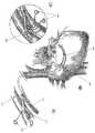
本発明の典型的な実施形態は、図1に図解されるように、管壁140内のカニューレ100を示し、グラフトである基端部分(図示せず)を備えている。カニューレの遠位端分は拡張可能な外部バルーン121を備えるカテーテル101を含む。 カテーテルは、当該技術分野で使用される、ポリウレタン、シリコーンゴム、他の適切なポリマー材料などで形成できる。遠位端は、モニター目的の圧力センサー124及び管を測定しそれに応じて外部バルーン121の寸法測定をするためのインピーダンス電極123を含む。 An exemplary embodiment of the present invention, as illustrated in FIG. 1, shows a
外部拡張可能バルーン121は、冠状静脈のカニューレを固定させる。さらに、外部バルーンは、カニューレを離れる血液の逆流を防止する。本実施形態において、第2の、内部バルーン122は、静脈のゆるやかな動脈化のために必要な圧力降下を提供する役割を果たす。バルーンは、その機能に適した材料で形成でき、これらに限定されることはないが、ポリエチレン、ラテックス、ポリエステルエタンまたはこれらの組み合わせを含む。バルーンは、カニューレ内の2次的空洞に接続でき、これは、一の実施形態においては、カニューレの基端部から出現する経皮的ポートと接続される。経皮的ポートは、逆かん流の間にバルーンを膨張させる、あるいは、収縮させるために使用される。一の典型的な実施形態において、静脈動脈化が完了したときには、内部バルーン122は2次的空洞を経て完全に取り除くことができる。図1において説明された実施形態の中では、外部バルーンおよび内部バルーンは、お互いに同心円状とすることができる。他の実施形態においては、内部および外部バルーンはカニューレの別個の部分に置くことができる。 External
他の典型的な実施形態は、カテーテルの遠位端120の近くで管を測定し、それに応じてバルーンの寸法を測定するために、2セットの4極性の電極123を含んでいてもよい。冠状静脈洞の選択的な領域は、参照によりその全体がここの組み入れられる、2004年2月19日に出願された、係属中の特許出願である米国特許出願No.10/782,149「管腔の器官の断面積と圧力勾配を測定するシステム及び方法」内により詳細に説明されているように、これらの励磁及び検出電極を使用して寸法測定することができる。その出願において、詳細な説明は、血管のサイズを決定するために使用されるコンダクタンスカテーテルを提供している。 Other exemplary embodiments may include two sets of
インピーダンス電極を含まないカニューレの実施形態においては、外部バルーンの寸法測定は、生体内及び生体外で測定されるバルーンのコンプライアンスに基づいても達成できる。この方法は、バルーン容積のキャリブレーションと、それゆえ、生体内での結果により生じる体外における直径とを必要とする。この代替的方法は、電極およびインピーダンス寸法測定の必要性を回避するが、それほど精度が高くないかもしれない。 In cannula embodiments that do not include an impedance electrode, external balloon dimensional measurements can also be achieved based on balloon compliance measured in vivo and in vitro. This method requires calibration of the balloon volume and hence the extracorporeal diameter resulting from in vivo results. This alternative method avoids the need for electrode and impedance dimension measurements, but may not be as accurate.
一旦、冠状静脈洞の適用可能な領域の空洞サイズが決定されると、バルーンはそれに応じて拡張する。静脈は、より低い圧力においてかなり柔軟であり、したがって、空洞の中にとどまるカニューレを保持するために適切な直径が選択される。緊急性の適用のためには、生理食塩水がバルーンを満たすために使用できる。より長期間の適用のためには、ゲルまたはシリコーンが、バルーンを満たすために使用できる。 Once the cavity size of the applicable area of the coronary sinus is determined, the balloon expands accordingly. The vein is fairly flexible at lower pressures, and therefore an appropriate diameter is selected to hold the cannula remaining in the cavity. For urgent applications, saline can be used to fill the balloon. For longer term applications, gels or silicones can be used to fill the balloon.
図2(A)は、管壁240内のカニューレ200の遠位端分を示す。カニューレの本体は、各種の可能な構成を備え、2つ以上の空洞を収容している。図2(B)においてそのいくつかを示す。説明された実施形態においては、カニューレは、主要な空洞203および複数の2次的空洞204を含んでいる。2次的空洞は、拡張可能な外部バルーン221および/または内部バルーン222と接続できる。2次的空洞は、逆かん流の間にカニューレの内部のモニターを可能にする圧力センサーも含むことができる。 FIG. 2A shows the distal end of the
主要な空洞203は、動脈から引き出された酸素処理された血流が冠状静脈洞に流入することを可能にする導管である。カテーテルの空洞は、要求された初期の圧力降下のための最適な狭窄部幾何学形状を提供し、冠状の静脈系の穏やかな流れを保証するように設計される。様々な実施形態において、2次的空洞204は、、内部および外部バルーンの膨張、収縮、除去、冠状静脈洞圧力測定、カニューレ圧力測定、および薬剤供給のなどの各種の目的のために使用できる。一の典型的な実施形態において、2次的空洞204は、それらが経皮的アクセスポートとして採用されることで、グラフト本体から分岐している基端拡張部と作用的にされる。 The
図3(A)は、カニューレの典型的な実施形態の詳細な説明を示し、その基端部がグラフト302であり、カニューレを通過している血液の圧力の降下を引き起こす狭窄部を含んでいる。狭窄部は、空洞を部分的に閉ざすバルーンの膨張により、または、空洞内に再吸収可能な材料を設けることにより、設けることができる。例えばポリオール類及びマグネシウム合金などの、各種の材料は、再吸収可能な狭窄部を構成するために使用できる。最も広く使われるポリオール類は、マンニトール、ソルビトール、およびマルチトールである。マンニトールは、ここに、本実施例の説明において使用される。コンピュータで計算された形状の型は、コンピュータ支援設計を用いて狭窄部を構成するために使用され、一方で、マグネシウム合金の幾何形状は、単一の管からレーザーにより彫造される。マンニトールは、食物、調剤、医療、および化学の産業において広く使われた自然に発生する非還元らせん状糖化合物である。結晶性のマンニトールは非常に低い吸湿性を示し、高い湿度で安定している製品において有用である。 FIG. 3A shows a detailed description of an exemplary embodiment of a cannula, the proximal end of which is a
マンニトールは、多くの場合、水溶液から急速に結晶化する傾向を有するので、乾燥たんぱく質製剤にバルク剤として加えられる。その性質に影響を与えることなく、アスピリンの有効成分であるアセチルサルチル酸がマンニトールと混合可能なことは、最近示された。狭窄部の再吸収の間に血液の凝結を防止することが、抗血栓特性を提供するので、理想的である。代わりに、現在では、薬剤溶出性のバイオ吸収性ステントに使用されているマグネシウム合金を使用可能である。マグネシウムは、有益な抗血栓性、抗不整脈性、および抗増殖性の性質を持つ自然の身体構成要素である。マグネシウム合金の分解速度は、リニアであり、2−3ヶ月の後に完了することが示されている。分解可能なマグネシウム合金の使用は、電気陰性であり、それゆえ、低血栓形成性表面をもたらす。必須の要素として、ゆっくりと分解するマグネシウムは組織を傷つけず、特に、非経口に与えられる場合には、0.5mol/lまではマグネシウム溶液は、良好な耐容性を示す。マグネシウム合金の機械的性質と腐食は、生理学上の条件の下で容易に制御可能で、分解可能な狭窄部の要件にマッチしている。そして、狭窄部型(mold)330は、基端側入口に非常に近いカニューレのカテーテル部分に挿入される。そして、グラフト302は図3(A)に示すように、この連結部で接着できる。 Mannitol often has a tendency to crystallize rapidly from aqueous solutions and is therefore added as a bulking agent to dry protein formulations. It has recently been shown that acetylsalicylic acid, the active ingredient of aspirin, can be mixed with mannitol without affecting its properties. Ideally, preventing blood clots during reabsorption of the stenosis provides antithrombotic properties. Instead, the magnesium alloys currently used for drug-eluting bioabsorbable stents can be used. Magnesium is a natural body component with beneficial antithrombotic, antiarrhythmic, and antiproliferative properties. The decomposition rate of the magnesium alloy is linear and has been shown to be complete after 2-3 months. The use of degradable magnesium alloys is electronegative and therefore results in a low thrombogenic surface. As an essential factor, the slowly degrading magnesium does not harm the tissue, especially when given parenterally, magnesium solutions up to 0.5 mol / l are well tolerated. The mechanical properties and corrosion of magnesium alloys are easily controlled under physiological conditions and match the requirements of degradable constrictions. The
マンニトールの再吸収レートは、分子量、結晶化度、および粒度の関数であることは注意すべきである。化合物は、約8週でそれが再吸収するように準備される。マグネシウム合金は、8−12週以内に再吸収することが示されている。 It should be noted that the resorption rate of mannitol is a function of molecular weight, crystallinity, and particle size. The compound is prepared so that it reabsorbs in about 8 weeks. Magnesium alloys have been shown to resorb within 8-12 weeks.
バルーン閉塞のために、要求された閉塞は、バルーンの膨張の間にカニューレの先端における圧力の測定により得られる。そして、いったん要求された中間的な圧力が得られると、バルーン容積は最終決定される。患者は、しばらくの期間の圧力において動脈化することを許される。そのような期間(一般に、2―3週)の終わりには、閉塞はバルーンの収縮により取り除かれる。典型的な実施形態では、内側バルーンを含んでいる内側の空洞が取り外し可能で、それゆえ引き抜き可能である。 Due to balloon occlusion, the required occlusion is obtained by measuring the pressure at the tip of the cannula during balloon inflation. And once the required intermediate pressure is obtained, the balloon volume is finally determined. The patient is allowed to arterize at some time of pressure. At the end of such a period (generally 2-3 weeks), the occlusion is removed by balloon deflation. In an exemplary embodiment, the inner cavity containing the inner balloon is removable and can therefore be withdrawn.
カニューレは、腋窩341または大腿部(図示せず)の静脈から冠状静脈洞の中に挿入される。基端側グラフト302は、隣接する動脈342に吻合される。グラフトは、周辺組織をサポートし血流から圧力に耐えるのに必要な強度と、動脈およびその内にカニューレが収納される静脈の間で吻合を成形するのに必要な柔軟性とを持つ、生体適合性、非吸収性のポリマーから形成できる。例えば、GORE-TEX(ポリテトラフルオロエチレン)などの材料は、グラフトにおいての使用に適当である。典型的な実施形態におけるグラフトの全体の長さは、約6cmであり、取り付けられたカテーテルのそれは8−10cmであるが、その寸法が人間の冠状静脈洞と鎖骨下動脈の間の吻合の形成を可能にするような長さであればよい。他の実施形態では、アクセスポート306は、2次的空洞に接続され、2次的空洞と流体が接触し、基端側グラフト302から分岐する。 The cannula is inserted into the coronary sinus from a vein in the
カニューレの直径は、特定の典型的な実施形態では、約4mmであるが、カニューレが十分な血流を与えて、関連する管に収容可能であるような直径であればよい。狭窄部の幾何形状は、約50mm Hgの圧力降下を保証し、十分に発展した流れを保証するための冠状静脈への十分な入口長さを確保するために様々に変えることができる。 The diameter of the cannula is about 4 mm in certain exemplary embodiments, but may be any diameter that allows the cannula to provide sufficient blood flow and be accommodated in the associated tube. The constriction geometry can be varied to ensure a pressure drop of about 50 mm Hg and to ensure sufficient entrance length to the coronary vein to ensure a fully developed flow.
本カニューレを使って自動的な逆かん流を実行するために、腋窩の静脈441および腋窩の動脈442は、図4(A)−(C)及び図5に示すように、露出される。同様の処置が、図5に示すように、大腿部の静脈543および大腿部の動脈544を使って実施できる。そして、カニューレ400の遠位端部分は、腋窩の静脈441に導入される。これは、周知のセルディンガー(Seldinger)テクニックを使って実施でき、このテクニックは、蛍光透視法の下でカニューレをガイドワイヤにかけることを含む。カニューレの遠位端の部分は、その時、脈管構造(例えば、鎖骨下静脈および優れた静脈大静脈)を通じて、および心臓の右心房に(蛍光透視法 直接的ビジョン、経食道的心エコー図、または他の適当な手段を介して)導かれる。カニューレの遠位端の部分は、右心房を通じて冠状静脈である冠状静脈洞446の中へ進められる。カニューレの遠位端の部分は、冠状静脈洞の要求された位置に到着する時には、洞の測定がされて、外部バルーンはそれに応じて膨らまされる。 To perform automatic retroperfusion using the cannula, the
次に、カニューレの基端側グラフト部分402及び動脈442の吻合405は、図4(C)に示すように、腋窩の動脈にグラフトセクションを縫合することによって達成される。このアプローチは、冠状静脈系の長期間の動脈化のために使用され、それは、冠状動脈バイパスグラフトを置換可能である。 Next, the
代わりに、自動逆かん流カニューレは、腋窩の静脈541および腋窩の動脈542及びクイックコネクタ545を通じて接続される両端での(局部麻酔の下の)経皮的穿刺によって挿入できる。この処置は、また、図5(B)に示すように、大腿部の静脈543及び動脈544を使って実施できる。この処置は、他の処置への橋渡しとして、患者を安定させるために、緊急の患者、または、短期間の冠状静脈の動脈化に用いることができる。 Alternatively, automatic reverse perfusion cannula can be inserted by percutaneous puncture (under local anesthesia) at both ends connected through
いったんカニューレが適所にあると、正常な順行性の血流は、平常通り継続するが、酸素処理された血液は、カニューレを通して冠状静脈洞を経て虚血性の心筋に自動的に逆かん流される。カニューレを通る酸素処理された血流は、心臓収縮期の終わり、及び、心臓拡張期の始めにおいて、拍動性の流れパターンを有するがピーク流れと圧力を有する心臓周期を通じて起こる。冠状静脈洞からの右心房への血液の逆流は、バルーンにより防止される。 Once the cannula is in place, normal antegrade blood flow continues normally, but oxygenated blood is automatically retroperfused through the cannula, through the coronary sinus, to the ischemic myocardium. . Oxygenated blood flow through the cannula occurs through the cardiac cycle with a pulsatile flow pattern but with peak flow and pressure at the end of systole and the beginning of diastole. The backflow of blood from the coronary sinus to the right atrium is prevented by the balloon.
局部麻酔の下で前記の処置を実施できることは注意すべきである。患者の特定の条件に依存して、自動逆かん流は、分、時、日、または月の間継続しうる。逆かん流の間に、2次的空洞は、冠状静脈洞圧力測定、および薬剤、細胞、遺伝子、または、成長因子の投与のために使用できる。2次的空洞に流体的に接続されたアクセスポート406、及びグラフトセクションは、皮下であることが予想される。 It should be noted that the above procedure can be performed under local anesthesia. Depending on the patient's specific conditions, automatic reperfusion may continue for minutes, hours, days, or months. During retroperfusion, the secondary cavity can be used for coronary sinus pressure measurements and administration of drugs, cells, genes, or growth factors. The
この方法は選択的な逆かん流に基づくので、カニューレが固定される冠状静脈洞のサイトと治療を要する心臓の領域との間に関係が存在する。図6は、興味あるいくつかのゾーンを示している。ゾーン1651は、図6(A)において前面から見た図及び図6(B)において背面から見た図に示され、左心室の前方および側部の壁に対応するLAD心室間前方静脈のレベルにおける逆かん流に対応している。これが、かん流する左心房の中で最も大きい領域であること、およびそれゆえ、客観的に最も関連している。この領域は、冠状静脈洞に対して最も遠位端にあり、インピーダンス電極を通じて静脈の寸法測定により決定できる。ゾーン2 652は、鈍い境目の回旋静脈のレベルをカバーし、冠状静脈洞に対してよりより基端側にある。ゾーン3 653は、後側部の回旋静脈のレベルをカバーしており、これはかん流する左心房の空洞の中で最も小さい領域であり、冠状静脈洞に対して最も基端側にある。したがって、インピーダンスの測定を通じて静脈の寸法測定により決定できるカテーテルの位置は、かん流領域を決定できる。これは、LADまたはLCx疾病をもつ患者を治療するための臨床の戦略として役立つ。 Because this method is based on selective retroperfusion, there is a relationship between the site of the coronary sinus where the cannula is secured and the region of the heart that requires treatment. FIG. 6 shows several zones of interest. Zone 1651 is shown in the front view in FIG. 6 (A) and the back view in FIG. 6 (B), and the level of the LAD interventricular anterior vein corresponding to the anterior and lateral walls of the left ventricle. Corresponds to reverse perfusion in This is the largest area in the perfused left atrium and is therefore most objectively relevant. This region is distal to the coronary sinus and can be determined by measuring the size of the vein through an impedance electrode.
本発明の典型的な実施形態の前述の開示物は、図解と説明の目的のために提示された。本発明を、開示された明確な形態に包括し、あるいは、限定することを意図していない。説明された実施形態の種々の変形と部分的な修正は、上記の開示物を考慮すれば当業者にとって明白である。本発明の範囲は、ここにおよびそれらの添付の特許請求の範囲及びその均等物のみにより規定されなければならない。 The foregoing disclosure of exemplary embodiments of the present invention has been presented for purposes of illustration and description. It is not intended to be exhaustive or to limit the invention to the precise forms disclosed. Various modifications and partial modifications of the described embodiments will be apparent to those skilled in the art in view of the above disclosure. The scope of the present invention should be defined only herein and by the appended claims and their equivalents.
さらに、本発明の代表的な実施形態を記述する際に、明細書は、特定のシーケンスのステップとして、本発明の方法および/またはプロセスを提示したかもしれない。しかしながら、方法またはプロセスは、ここに記述された特定のステップの順序に依存していないで、方法またはプロセスは、説明された特定のシーケンスのステップに限定されるべきではない。当業者は、他のシーケンスのステップを想起可能である。従って、明細書に記述された特定の順序のステップは、請求項を限定するものとして解釈されるべきではない。さらに、本発明の方法および/またはプロセスを対象とする請求項は、記載された順序でそのステップの実施に限定されるべきでなく、当業者であれば、そのシーケンスが変更され、本発明の精神及び範囲内にあることをすぐに理解できる。 Further, in describing representative embodiments of the present invention, the specification may have presented the method and / or process of the present invention as a particular sequence of steps. However, the method or process does not depend on the particular order of steps described herein, and the method or process should not be limited to the particular sequence of steps described. One skilled in the art can conceive of other sequence steps. Accordingly, the specific order of steps described in the specification should not be construed as limiting the claims. Furthermore, claims directed to the methods and / or processes of the present invention should not be limited to the implementation of the steps in the order described, but those skilled in the art can alter the sequence and You can immediately understand that it is within the spirit and scope.
Claims (17)
Translated fromJapanese空洞、高い血圧を有する領域と接触する基端部、及び、低い血圧を有する領域と接触する遠位端を有する細長の本体と;
前記細長の本体の前記空洞内の前記基端部と遠位端の間に配置された再吸収可能な狭窄部と;を有し、
前記再吸収可能な狭窄部は、基端部から遠位端へ向かう血流によって時間内に再吸収され、その結果、遠位端における領域の血圧を前記基端部の領域の血圧によって徐々に平均化する、
ことを特徴とする機器。A device for controlling blood perfusion pressure in a tube:
An elongated body having a cavity, a proximal end in contact with the region having high blood pressure, and a distal end in contact with the region having low blood pressure;
A resorbable constriction disposed between the proximal and distal ends within the cavity of the elongate body;
The resorbable stenosis is reabsorbed in time by blood flow from the proximal end to the distal end, so that the blood pressure in the region at the distal end is gradually increased by the blood pressure in the region at the proximal end. To average,
Equipment characterized by that.
空洞、高い血圧を有する領域と接触する基端部、及び、低い血圧を有する領域と接触する遠位端を有する細長の本体と;
前記基端部と遠位端の間の前記細長の本体の空洞内に位置決めされたバルーン閉塞部と;を有し、
前記バルーン閉塞部は、最初に、前記空洞を部分的に閉ざすために満たされるけれども、周期時間の経過後に収縮するか、または、除去され、その結果、遠位端における領域の血圧を前記基端部の領域の血圧によって徐々に平均化する、
ことを特徴とする機器。A device for controlling blood perfusion pressure in a tube:
An elongated body having a cavity, a proximal end in contact with the region having high blood pressure, and a distal end in contact with the region having low blood pressure;
A balloon occlusion positioned within the elongated body cavity between the proximal and distal ends;
The balloon occlusion is initially filled to partially close the cavity, but contracts or is removed after a period of time has passed, so that the blood pressure of the region at the distal end is reduced to the proximal end. Gradually average by the blood pressure in the area of the
Equipment characterized by that.
空洞、高い血圧を有する領域と接触する基端部、及び、低い血圧を有する領域と接触する遠位端を有する細長の本体と;
前記細長の本体の前記空洞内の前記基端部と遠位端の間に配置された再吸収可能な狭窄部と;を有し、
前記再吸収可能な狭窄部は、基端部から遠位端へ向かう血流によって時間内に再吸収され、その結果、遠位端における領域の血圧を前記基端部の領域の血圧によって徐々に平均化する、
ことを特徴とするカニューレ。A cannula for generating a retrograde flow within a portion of the circulatory system comprising:
An elongated body having a cavity, a proximal end in contact with the region having high blood pressure, and a distal end in contact with the region having low blood pressure;
A resorbable constriction disposed between the proximal and distal ends within the cavity of the elongate body;
The resorbable stenosis is reabsorbed in time by blood flow from the proximal end to the distal end, so that the blood pressure in the region at the distal end is gradually increased by the blood pressure in the region at the proximal end. To average,
A cannula characterized by that.
Applications Claiming Priority (3)
| Application Number | Priority Date | Filing Date | Title |
|---|---|---|---|
| US70342205P | 2005-07-29 | 2005-07-29 | |
| US60/703,422 | 2005-07-29 | ||
| PCT/US2006/029223WO2007016260A2 (en) | 2005-07-29 | 2006-07-28 | Devices and methods for controlling blood perfusion pressure using a retrograde cannula |
Publications (2)
| Publication Number | Publication Date |
|---|---|
| JP2009502348A JP2009502348A (en) | 2009-01-29 |
| JP4809894B2true JP4809894B2 (en) | 2011-11-09 |
Family
ID=37709179
Family Applications (1)
| Application Number | Title | Priority Date | Filing Date |
|---|---|---|---|
| JP2008524152AExpired - Fee RelatedJP4809894B2 (en) | 2005-07-29 | 2006-07-28 | Apparatus and method for controlling blood pressure using a reverse perfusion cannula |
Country Status (7)
| Country | Link |
|---|---|
| US (7) | US8231646B2 (en) |
| EP (1) | EP1912697B1 (en) |
| JP (1) | JP4809894B2 (en) |
| AU (1) | AU2006275788B2 (en) |
| CA (1) | CA2617154C (en) |
| NZ (1) | NZ565570A (en) |
| WO (1) | WO2007016260A2 (en) |
Families Citing this family (46)
| Publication number | Priority date | Publication date | Assignee | Title |
|---|---|---|---|---|
| GB0419954D0 (en) | 2004-09-08 | 2004-10-13 | Advotek Medical Devices Ltd | System for directing therapy |
| JP4809894B2 (en) | 2005-07-29 | 2011-11-09 | シーブイデバイシズ リミテッド ライアビリティ カンパニー | Apparatus and method for controlling blood pressure using a reverse perfusion cannula |
| US20130190676A1 (en) | 2006-04-20 | 2013-07-25 | Limflow Gmbh | Devices and methods for fluid flow through body passages |
| US11045300B2 (en) | 2008-12-19 | 2021-06-29 | Cvdevices, Llc | Systems, devices, and methods for organ retroperfusion along with regional mild hypothermia |
| EP2379130B1 (en)* | 2008-12-19 | 2018-02-28 | CVDevices, LLC | Autoretroperfusion devices and systems |
| US8968230B2 (en) | 2011-08-30 | 2015-03-03 | Cvdevices, Llc | Coil occlusion devices and systems and methods of using the same |
| US8945039B2 (en) | 2008-12-19 | 2015-02-03 | Cvdevices, Llc | Devices, systems, and methods for organ retroperfusion |
| US9968727B2 (en) | 2008-12-19 | 2018-05-15 | Cvdevices, Llc | Systems, devices, and methods for organ retroperfusion along with regional mild hypothermia |
| US9504781B2 (en) | 2008-12-19 | 2016-11-29 | Cvdevices, Llc | Peripheral arterialization devices and methods of using the same |
| US8888733B2 (en)* | 2008-12-19 | 2014-11-18 | Cvdevices, Llc | Devices, systems, and methods for autoretroperfusion |
| WO2010099231A2 (en)* | 2009-02-24 | 2010-09-02 | Conformis, Inc. | Automated systems for manufacturing patient-specific orthopedic implants and instrumentation |
| US8579964B2 (en) | 2010-05-05 | 2013-11-12 | Neovasc Inc. | Transcatheter mitral valve prosthesis |
| US11337707B2 (en)* | 2010-05-25 | 2022-05-24 | Miracor Medical Sa | Treating heart tissue |
| US8267887B2 (en)* | 2010-05-26 | 2012-09-18 | Miracor Medical Systems Gmbh | Treating heart tissue |
| US9554897B2 (en) | 2011-04-28 | 2017-01-31 | Neovasc Tiara Inc. | Methods and apparatus for engaging a valve prosthesis with tissue |
| US9308087B2 (en) | 2011-04-28 | 2016-04-12 | Neovasc Tiara Inc. | Sequentially deployed transcatheter mitral valve prosthesis |
| EP2765907B1 (en) | 2011-10-14 | 2016-05-18 | Acist Medical Systems, Inc. | Device for measuring an anatomical structure |
| US9549679B2 (en) | 2012-05-14 | 2017-01-24 | Acist Medical Systems, Inc. | Multiple transducer delivery device and method |
| US9345573B2 (en) | 2012-05-30 | 2016-05-24 | Neovasc Tiara Inc. | Methods and apparatus for loading a prosthesis onto a delivery system |
| US9808342B2 (en) | 2012-07-03 | 2017-11-07 | St. Jude Medical, Cardiology Division, Inc. | Balloon sizing device and method of positioning a prosthetic heart valve |
| US10835367B2 (en) | 2013-03-08 | 2020-11-17 | Limflow Gmbh | Devices for fluid flow through body passages |
| CA2898879C (en) | 2013-03-08 | 2023-05-02 | Limflow Gmbh | Methods and systems for providing or maintaining fluid flow through body passages |
| US9572665B2 (en) | 2013-04-04 | 2017-02-21 | Neovasc Tiara Inc. | Methods and apparatus for delivering a prosthetic valve to a beating heart |
| WO2015017714A2 (en) | 2013-07-31 | 2015-02-05 | Cvdevices, Llc | Unitary body systems and devices and methods to use the same for retroperfusion |
| US9545263B2 (en) | 2014-06-19 | 2017-01-17 | Limflow Gmbh | Devices and methods for treating lower extremity vasculature |
| US9924905B2 (en)* | 2015-03-09 | 2018-03-27 | Graftworx, Inc. | Sensor position on a prosthesis for detection of a stenosis |
| EP3302254B1 (en)* | 2015-05-29 | 2021-06-23 | Carag Ag | Catheter for measuring the blood flow of a body tissue |
| CA3007660A1 (en) | 2015-12-15 | 2017-06-22 | Neovasc Tiara Inc. | Transseptal delivery system |
| US10433952B2 (en) | 2016-01-29 | 2019-10-08 | Neovasc Tiara Inc. | Prosthetic valve for avoiding obstruction of outflow |
| CA3042588A1 (en) | 2016-11-21 | 2018-05-24 | Neovasc Tiara Inc. | Methods and systems for rapid retraction of a transcatheter heart valve delivery system |
| US10612405B2 (en) | 2017-01-13 | 2020-04-07 | United Technologies Corporation | Stator outer platform sealing and retainer |
| CN106618803B (en)* | 2017-02-08 | 2018-10-02 | 上海纽脉太惟医疗科技有限公司 | A kind of artificial heart valve film conveying device |
| EP3609415B1 (en) | 2017-04-10 | 2023-08-23 | LimFlow GmbH | Devices for treating lower extremity vasculature |
| CA3073834A1 (en) | 2017-08-25 | 2019-02-28 | Neovasc Tiara Inc. | Sequentially deployed transcatheter mitral valve prosthesis |
| US10876833B2 (en)* | 2018-03-26 | 2020-12-29 | International Business Machines Corporation | Apparatus and method for measuring micrometer scale features of electronic component over millimeter scale distances to nanometer scale precision |
| CN112469332B (en)* | 2018-07-26 | 2024-08-06 | 学校法人早稻田大学 | Diagnosis support system for ischemic heart disease |
| SG11202102500UA (en) | 2018-10-09 | 2021-04-29 | Limflow Gmbh | Devices and methods for catheter alignment |
| CN113271890B (en) | 2018-11-08 | 2024-08-30 | 内奥瓦斯克迪亚拉公司 | Ventricular deployment of transcatheter mitral valve prosthesis |
| CA3132873A1 (en) | 2019-03-08 | 2020-09-17 | Neovasc Tiara Inc. | Retrievable prosthesis delivery system |
| CA3135753C (en) | 2019-04-01 | 2023-10-24 | Neovasc Tiara Inc. | Controllably deployable prosthetic valve |
| US11491006B2 (en) | 2019-04-10 | 2022-11-08 | Neovasc Tiara Inc. | Prosthetic valve with natural blood flow |
| US11779742B2 (en) | 2019-05-20 | 2023-10-10 | Neovasc Tiara Inc. | Introducer with hemostasis mechanism |
| JP7520897B2 (en) | 2019-06-20 | 2024-07-23 | ニオバスク ティアラ インコーポレイテッド | Thin prosthetic mitral valve |
| CN110353752B (en)* | 2019-06-28 | 2021-05-25 | 北京康瑞迪医疗科技有限公司 | Heart coronary vein blood flow blocking device |
| EP4051174A4 (en) | 2019-11-01 | 2023-11-22 | LimFlow GmbH | Devices and methods for increasing blood perfusion to a distal extremity |
| CN111631700B (en)* | 2020-05-25 | 2021-08-10 | 华南理工大学 | System for regulating blood pressure according to optimal blood pressure target value |
Citations (6)
| Publication number | Priority date | Publication date | Assignee | Title |
|---|---|---|---|---|
| JPS62500150A (en)* | 1984-09-05 | 1987-01-22 | クオティディアン・ナンバーワンハンドレッド・プロプライエタリー・リミテッド | blood flow control |
| JPH05504075A (en)* | 1989-12-07 | 1993-07-01 | メドトロニック インコーポレーテッド | Coronary local perfusion pump that can be implanted subcutaneously |
| JPH10146350A (en)* | 1996-08-13 | 1998-06-02 | Heartstent Llc | Coronary artery by-pass forming device |
| JP2001503291A (en)* | 1996-09-16 | 2001-03-13 | サーキュレイション,インコーポレイテッド | Device for treating ischemic heart disease by providing transvenous myocardial perfusion |
| JP2001505786A (en)* | 1996-11-04 | 2001-05-08 | パジェット ミルソム,フレデリク | Heart recovery device |
| JP2001527440A (en)* | 1997-04-11 | 2001-12-25 | トランスバスキュラー インコーポレイテッド | Method and device for myocardial penetrating direct coronary remodeling |
Family Cites Families (38)
| Publication number | Priority date | Publication date | Assignee | Title |
|---|---|---|---|---|
| FR2502499B1 (en) | 1981-03-27 | 1987-01-23 | Farcot Jean Christian | APPARATUS FOR BLOOD RETROPERFUSION, IN PARTICULAR FOR THE TREATMENT OF INFARCTUS BY INJECTION OF ARTERIAL BLOOD INTO THE CORONARY SINUS |
| US4850969A (en) | 1987-10-01 | 1989-07-25 | Retroperfusion Systems, Inc. | Retroperfusion catheter and tip construction for use therewith |
| US4917667A (en) | 1988-02-11 | 1990-04-17 | Retroperfusion Systems, Inc. | Retroperfusion balloon catheter and method |
| US4927412A (en) | 1988-12-08 | 1990-05-22 | Retroperfusion Systems, Inc. | Coronary sinus catheter |
| US5597377A (en) | 1994-05-06 | 1997-01-28 | Trustees Of Boston University | Coronary sinus reperfusion catheter |
| US5833662A (en)* | 1995-01-19 | 1998-11-10 | Stevens; Robert C. | Hemostasis cannula system |
| US5785679A (en)* | 1995-07-19 | 1998-07-28 | Endotex Interventional Systems, Inc. | Methods and apparatus for treating aneurysms and arterio-venous fistulas |
| FI954565A0 (en) | 1995-09-27 | 1995-09-27 | Biocon Oy | Biologically applied polymeric material to the implant and foil preparation |
| US6447539B1 (en) | 1996-09-16 | 2002-09-10 | Transvascular, Inc. | Method and apparatus for treating ischemic heart disease by providing transvenous myocardial perfusion |
| US6186972B1 (en) | 1996-09-16 | 2001-02-13 | James A. Nelson | Methods and apparatus for treating ischemic heart disease by providing transvenous myocardial perfusion |
| WO1999004845A2 (en)* | 1997-07-22 | 1999-02-04 | Chase Medical Inc. | Catheter having a lumen occluding balloon and method of use thereof |
| US5908407A (en) | 1997-07-25 | 1999-06-01 | Neuroperfusion, Inc. | Retroperfusion catheter apparatus and method |
| US6234995B1 (en)* | 1998-11-12 | 2001-05-22 | Advanced Interventional Technologies, Inc. | Apparatus and method for selectively isolating a proximal anastomosis site from blood in an aorta |
| US6368346B1 (en)* | 1999-06-03 | 2002-04-09 | American Medical Systems, Inc. | Bioresorbable stent |
| US6926689B2 (en) | 2002-03-13 | 2005-08-09 | Albertus Scheule | Aortic balloon occlusion cannula |
| US6500145B1 (en)* | 2000-02-08 | 2002-12-31 | California Medical Laboratories, Inc. | Retrograde cardioplegia catheter |
| US20020077581A1 (en) | 2000-12-19 | 2002-06-20 | Alan Davidner | Simplified cerebral retroperfusion apparatus and method |
| US6562066B1 (en) | 2001-03-02 | 2003-05-13 | Eric C. Martin | Stent for arterialization of the coronary sinus and retrograde perfusion of the myocardium |
| US8292908B2 (en)* | 2001-06-29 | 2012-10-23 | World Heart Corporation | Endoscopic cannulation apparatus and method |
| US6638253B2 (en)* | 2001-07-17 | 2003-10-28 | Eugene Michael Breznock | Method and apparatus for chest drainage |
| AT410396B (en) | 2001-07-17 | 2003-04-25 | Mohl Werner Ddr | DEVICE FOR THE INTERMITTENT OCCLUSION OF THE CORONARY SINE |
| US20030065386A1 (en)* | 2001-09-28 | 2003-04-03 | Weadock Kevin Shaun | Radially expandable endoprosthesis device with two-stage deployment |
| AU2003221976A1 (en)* | 2002-04-16 | 2003-11-03 | Tyco Healthcare Group Lp | Method and apparatus for anastomosis including an expandable anchor |
| US20030181843A1 (en) | 2002-06-11 | 2003-09-25 | Scout Medical Technologies, Llc | Device and method providing arterial blood flow for perfusion of ischemic myocardium |
| US8540618B2 (en)* | 2003-01-31 | 2013-09-24 | L-Vad Technology, Inc. | Stable aortic blood pump implant |
| US7004926B2 (en) | 2003-02-25 | 2006-02-28 | Cleveland Clinic Foundation | Apparatus and method for auto-retroperfusion of a coronary vein |
| WO2004075951A2 (en) | 2003-02-25 | 2004-09-10 | The Cleveland Clinic Foundation | Apparatus and method for auto-retroperfusion of a coronary vein |
| US7473237B2 (en) | 2003-02-25 | 2009-01-06 | The Cleveland Clinic Foundation | Apparatus for auto-retroperfusion of a coronary vein |
| US7566317B1 (en)* | 2003-07-07 | 2009-07-28 | Stanley Batiste | A-V dialysis graft |
| US7819856B2 (en)* | 2004-10-05 | 2010-10-26 | Nexeon Medical Systems, Inc. | Methods and apparatus for treating infarcted regions of tissue following acute myocardial infarction |
| US20060085028A1 (en)* | 2004-10-18 | 2006-04-20 | Robert Boock | Vessel occlusion system |
| WO2006058290A2 (en) | 2004-11-26 | 2006-06-01 | The Regents Of The University Of California | Devices, systems and methods for arterializations of venous blood vessels prior to retroperfusion |
| US20070010781A1 (en) | 2005-06-27 | 2007-01-11 | Venkataramana Vijay | Implantable aorto-coronary sinus shunt for myocardial revascularization |
| JP4809894B2 (en)* | 2005-07-29 | 2011-11-09 | シーブイデバイシズ リミテッド ライアビリティ カンパニー | Apparatus and method for controlling blood pressure using a reverse perfusion cannula |
| GB0718943D0 (en)* | 2007-09-28 | 2007-11-07 | Univ Nottingham | Mechanical support |
| US8322347B2 (en)* | 2009-02-27 | 2012-12-04 | Cvdevices, Llc | Systems and methods for selective auto-retroperfusion of the cerebral venous system |
| EP3620202B1 (en)* | 2010-02-02 | 2023-06-14 | NirvaMed, Inc. | Localized therapy delivery and local organ protection |
| US20130190682A1 (en)* | 2011-07-26 | 2013-07-25 | Peter M. Bonutti | Methods and systems for controlling medical environments |
- 2006
- 2006-07-28JPJP2008524152Apatent/JP4809894B2/ennot_activeExpired - Fee Related
- 2006-07-28NZNZ565570Apatent/NZ565570A/ennot_activeIP Right Cessation
- 2006-07-28AUAU2006275788Apatent/AU2006275788B2/ennot_activeCeased
- 2006-07-28WOPCT/US2006/029223patent/WO2007016260A2/enactiveApplication Filing
- 2006-07-28EPEP06774707.1Apatent/EP1912697B1/enactiveActive
- 2006-07-28USUS11/997,139patent/US8231646B2/enactiveActive
- 2006-07-28CACA 2617154patent/CA2617154C/enactiveActive
- 2012
- 2012-07-31USUS13/562,602patent/US9132010B2/ennot_activeExpired - Fee Related
- 2013
- 2013-08-13USUS13/965,548patent/US9675458B2/ennot_activeExpired - Fee Related
- 2015
- 2015-09-15USUS14/854,722patent/US9579201B2/ennot_activeExpired - Fee Related
- 2017
- 2017-02-28USUS15/445,116patent/US10285814B2/enactiveActive
- 2017-06-12USUS15/620,359patent/US10702387B2/ennot_activeExpired - Fee Related
- 2020
- 2020-07-07USUS16/922,658patent/US11771558B2/enactiveActive
Patent Citations (6)
| Publication number | Priority date | Publication date | Assignee | Title |
|---|---|---|---|---|
| JPS62500150A (en)* | 1984-09-05 | 1987-01-22 | クオティディアン・ナンバーワンハンドレッド・プロプライエタリー・リミテッド | blood flow control |
| JPH05504075A (en)* | 1989-12-07 | 1993-07-01 | メドトロニック インコーポレーテッド | Coronary local perfusion pump that can be implanted subcutaneously |
| JPH10146350A (en)* | 1996-08-13 | 1998-06-02 | Heartstent Llc | Coronary artery by-pass forming device |
| JP2001503291A (en)* | 1996-09-16 | 2001-03-13 | サーキュレイション,インコーポレイテッド | Device for treating ischemic heart disease by providing transvenous myocardial perfusion |
| JP2001505786A (en)* | 1996-11-04 | 2001-05-08 | パジェット ミルソム,フレデリク | Heart recovery device |
| JP2001527440A (en)* | 1997-04-11 | 2001-12-25 | トランスバスキュラー インコーポレイテッド | Method and device for myocardial penetrating direct coronary remodeling |
Also Published As
| Publication number | Publication date |
|---|---|
| WO2007016260A3 (en) | 2007-05-31 |
| US11771558B2 (en) | 2023-10-03 |
| US10702387B2 (en) | 2020-07-07 |
| US9579201B2 (en) | 2017-02-28 |
| US20200405487A1 (en) | 2020-12-31 |
| EP1912697B1 (en) | 2016-09-14 |
| CA2617154C (en) | 2015-02-03 |
| US20160000568A1 (en) | 2016-01-07 |
| EP1912697A2 (en) | 2008-04-23 |
| US20170165410A1 (en) | 2017-06-15 |
| US20080234658A1 (en) | 2008-09-25 |
| JP2009502348A (en) | 2009-01-29 |
| US9132010B2 (en) | 2015-09-15 |
| US20170273791A1 (en) | 2017-09-28 |
| EP1912697A4 (en) | 2015-03-11 |
| AU2006275788A1 (en) | 2007-02-08 |
| US20120296368A1 (en) | 2012-11-22 |
| US10285814B2 (en) | 2019-05-14 |
| US9675458B2 (en) | 2017-06-13 |
| US8231646B2 (en) | 2012-07-31 |
| AU2006275788B2 (en) | 2012-07-26 |
| WO2007016260A2 (en) | 2007-02-08 |
| NZ565570A (en) | 2011-08-26 |
| US20140039538A1 (en) | 2014-02-06 |
| CA2617154A1 (en) | 2007-02-08 |
Similar Documents
| Publication | Publication Date | Title |
|---|---|---|
| JP4809894B2 (en) | Apparatus and method for controlling blood pressure using a reverse perfusion cannula | |
| US11406803B2 (en) | System and method for reducing pulsatile pressure | |
| US10736729B2 (en) | Peripheral arterialization devices and methods of using the same | |
| JP5513520B2 (en) | Automatic retrograde perfusion device, system and method for achieving arterialization of venous blood | |
| US11045300B2 (en) | Systems, devices, and methods for organ retroperfusion along with regional mild hypothermia | |
| US20060064059A1 (en) | Treatment of infarct expansion by partially occluding vena cava | |
| JP2016532491A (en) | Single-body system and device and method of using retrograde perfusion | |
| WO1997037716A1 (en) | Multichannel catheter | |
| JPS60227774A (en) | Heart muscle treating method and inverse injection catheter of physiological agent | |
| US6325813B1 (en) | Method and apparatus for stabilizing vascular wall | |
| JP2009525791A (en) | Medical vascular lock with occlusion | |
| CN116420081A (en) | Device and method for repairing tissue | |
| Vince et al. | A prosthesis for banding the main pulmonary artery, capable of serial dilatation by balloon angioplasty | |
| CN117323064A (en) | left ventricular volume reduction device | |
| CN120532026A (en) | IABP catheter |
Legal Events
| Date | Code | Title | Description |
|---|---|---|---|
| A621 | Written request for application examination | Free format text:JAPANESE INTERMEDIATE CODE: A621 Effective date:20090715 | |
| A977 | Report on retrieval | Free format text:JAPANESE INTERMEDIATE CODE: A971007 Effective date:20110415 | |
| A131 | Notification of reasons for refusal | Free format text:JAPANESE INTERMEDIATE CODE: A131 Effective date:20110419 | |
| A521 | Request for written amendment filed | Free format text:JAPANESE INTERMEDIATE CODE: A523 Effective date:20110705 | |
| TRDD | Decision of grant or rejection written | ||
| A01 | Written decision to grant a patent or to grant a registration (utility model) | Free format text:JAPANESE INTERMEDIATE CODE: A01 Effective date:20110729 | |
| A01 | Written decision to grant a patent or to grant a registration (utility model) | Free format text:JAPANESE INTERMEDIATE CODE: A01 | |
| A61 | First payment of annual fees (during grant procedure) | Free format text:JAPANESE INTERMEDIATE CODE: A61 Effective date:20110819 | |
| FPAY | Renewal fee payment (event date is renewal date of database) | Free format text:PAYMENT UNTIL: 20140826 Year of fee payment:3 | |
| R150 | Certificate of patent or registration of utility model | Ref document number:4809894 Country of ref document:JP Free format text:JAPANESE INTERMEDIATE CODE: R150 | |
| R250 | Receipt of annual fees | Free format text:JAPANESE INTERMEDIATE CODE: R250 | |
| R250 | Receipt of annual fees | Free format text:JAPANESE INTERMEDIATE CODE: R250 | |
| R250 | Receipt of annual fees | Free format text:JAPANESE INTERMEDIATE CODE: R250 | |
| R250 | Receipt of annual fees | Free format text:JAPANESE INTERMEDIATE CODE: R250 | |
| R250 | Receipt of annual fees | Free format text:JAPANESE INTERMEDIATE CODE: R250 | |
| R250 | Receipt of annual fees | Free format text:JAPANESE INTERMEDIATE CODE: R250 | |
| R250 | Receipt of annual fees | Free format text:JAPANESE INTERMEDIATE CODE: R250 | |
| R250 | Receipt of annual fees | Free format text:JAPANESE INTERMEDIATE CODE: R250 | |
| R250 | Receipt of annual fees | Free format text:JAPANESE INTERMEDIATE CODE: R250 | |
| LAPS | Cancellation because of no payment of annual fees |