JP4806717B2 - Image processing system - Google Patents
Image processing systemDownload PDFInfo
- Publication number
- JP4806717B2 JP4806717B2JP2009151394AJP2009151394AJP4806717B2JP 4806717 B2JP4806717 B2JP 4806717B2JP 2009151394 AJP2009151394 AJP 2009151394AJP 2009151394 AJP2009151394 AJP 2009151394AJP 4806717 B2JP4806717 B2JP 4806717B2
- Authority
- JP
- Japan
- Prior art keywords
- image
- image data
- unit
- editing
- reading
- Prior art date
- Legal status (The legal status is an assumption and is not a legal conclusion. Google has not performed a legal analysis and makes no representation as to the accuracy of the status listed.)
- Expired - Fee Related
Links
- 238000012545processingMethods0.000titleclaimsdescription65
- 238000001514detection methodMethods0.000claimsabstractdescription14
- 230000005856abnormalityEffects0.000claimsdescription16
- 238000003860storageMethods0.000claimsdescription11
- 238000012546transferMethods0.000claimsdescription7
- 238000000034methodMethods0.000description132
- 238000013500data storageMethods0.000description49
- 230000005540biological transmissionEffects0.000description43
- 238000012790confirmationMethods0.000description39
- 238000010586diagramMethods0.000description24
- 238000012217deletionMethods0.000description16
- 230000037430deletionEffects0.000description16
- 238000012544monitoring processMethods0.000description11
- 230000006870functionEffects0.000description9
- 230000000694effectsEffects0.000description4
- 230000015572biosynthetic processEffects0.000description3
- 230000002159abnormal effectEffects0.000description2
- 238000006243chemical reactionMethods0.000description2
- 238000003754machiningMethods0.000description2
- 238000012986modificationMethods0.000description2
- 230000004048modificationEffects0.000description2
- 238000004891communicationMethods0.000description1
- 230000006835compressionEffects0.000description1
- 238000007906compressionMethods0.000description1
- 238000007726management methodMethods0.000description1
- 238000002360preparation methodMethods0.000description1
- 238000003825pressingMethods0.000description1
- 238000004904shorteningMethods0.000description1
- 230000009466transformationEffects0.000description1
Images


Classifications
- H—ELECTRICITY
- H04—ELECTRIC COMMUNICATION TECHNIQUE
- H04N—PICTORIAL COMMUNICATION, e.g. TELEVISION
- H04N1/00—Scanning, transmission or reproduction of documents or the like, e.g. facsimile transmission; Details thereof
- H04N1/00567—Handling of original or reproduction media, e.g. cutting, separating, stacking
- H04N1/00663—Indicating relating to handling of media
- H—ELECTRICITY
- H04—ELECTRIC COMMUNICATION TECHNIQUE
- H04N—PICTORIAL COMMUNICATION, e.g. TELEVISION
- H04N1/00—Scanning, transmission or reproduction of documents or the like, e.g. facsimile transmission; Details thereof
- H04N1/0035—User-machine interface; Control console
- H04N1/00405—Output means
- H04N1/00408—Display of information to the user, e.g. menus
- H04N1/0044—Display of information to the user, e.g. menus for image preview or review, e.g. to help the user position a sheet
- H04N1/00442—Simultaneous viewing of a plurality of images, e.g. using a mosaic display arrangement of thumbnails
- H04N1/00445—Simultaneous viewing of a plurality of images, e.g. using a mosaic display arrangement of thumbnails arranged in a one dimensional array
- H04N1/00448—Simultaneous viewing of a plurality of images, e.g. using a mosaic display arrangement of thumbnails arranged in a one dimensional array horizontally
- H—ELECTRICITY
- H04—ELECTRIC COMMUNICATION TECHNIQUE
- H04N—PICTORIAL COMMUNICATION, e.g. TELEVISION
- H04N1/00—Scanning, transmission or reproduction of documents or the like, e.g. facsimile transmission; Details thereof
- H04N1/0035—User-machine interface; Control console
- H04N1/00405—Output means
- H04N1/00408—Display of information to the user, e.g. menus
- H04N1/0044—Display of information to the user, e.g. menus for image preview or review, e.g. to help the user position a sheet
- H04N1/00461—Display of information to the user, e.g. menus for image preview or review, e.g. to help the user position a sheet marking or otherwise tagging one or more displayed image, e.g. for selective reproduction
- H—ELECTRICITY
- H04—ELECTRIC COMMUNICATION TECHNIQUE
- H04N—PICTORIAL COMMUNICATION, e.g. TELEVISION
- H04N1/00—Scanning, transmission or reproduction of documents or the like, e.g. facsimile transmission; Details thereof
- H04N1/00567—Handling of original or reproduction media, e.g. cutting, separating, stacking
- H04N1/0057—Conveying sheets before or after scanning
- H—ELECTRICITY
- H04—ELECTRIC COMMUNICATION TECHNIQUE
- H04N—PICTORIAL COMMUNICATION, e.g. TELEVISION
- H04N1/00—Scanning, transmission or reproduction of documents or the like, e.g. facsimile transmission; Details thereof
- H04N1/00567—Handling of original or reproduction media, e.g. cutting, separating, stacking
- H04N1/00628—Separating, e.g. preventing feeding of two sheets at a time
- H—ELECTRICITY
- H04—ELECTRIC COMMUNICATION TECHNIQUE
- H04N—PICTORIAL COMMUNICATION, e.g. TELEVISION
- H04N1/00—Scanning, transmission or reproduction of documents or the like, e.g. facsimile transmission; Details thereof
- H04N1/00567—Handling of original or reproduction media, e.g. cutting, separating, stacking
- H04N1/00644—Counting or calculating, e.g. a number of remaining sheets
Landscapes
- Engineering & Computer Science (AREA)
- Multimedia (AREA)
- Signal Processing (AREA)
- Human Computer Interaction (AREA)
- Facsimiles In General (AREA)
- Facsimile Scanning Arrangements (AREA)
- Accessory Devices And Overall Control Thereof (AREA)
- Exposure Or Original Feeding In Electrophotography (AREA)
- Control Or Security For Electrophotography (AREA)
Abstract
Description
Translated fromJapanese本発明は、画像読み取り装置により読み取った画像の画像データを処理する画像処理システムに関するものである。The present invention relatesto an image processing systemfor processing image data of an image readby an image reading apparatus.
従来、スキャナ装置のような画像読み取り装置は、例えば、下記の特許文献1に記載されているように、画像(イメージ)を読取って画像データを生成する読み取り手段と、読取られた画像データを圧縮処理して圧縮データを生成する圧縮手段と、その圧縮データを一旦格納する記憶手段と、格納された圧縮データの画像容量(画像サイズ)を調整して送信用画像データを生成する画像容量調整手段と、調整された送信用画像データを電子メール(以下「Email」という。)の添付ファイルとして送信するものであった。読み取った画像データをEmailの添付ファイルの形で送信する機能をScanToEmail機能という。 2. Description of the Related Art Conventionally, an image reading apparatus such as a scanner apparatus, as described in, for example,
しかしながら、従来の画像読み取り装置では、原稿が重送等の障害が発生しても分からず、意図した原稿枚数より少ない枚数の画像データが送信されることがあった。 However, in the conventional image reading apparatus, even when a failure such as double feeding occurs in a document, it is not known and image data of a smaller number than the intended number of documents may be transmitted.
本発明の画像処理システムは、画像読み取り装置により読み取った画像の画像データを画像処理装置へ送信して編集を行うシステムである。
そして、前記画像読み取り装置は、複数枚載置された前記原稿を順次一枚ずつ分離搬送可能な原稿搬送手段と、前記原稿搬送手段によって搬送される前記原稿上の前記画像を読取って前記画像データを出力する画像読み取り手段と、前記画像読み取り手段で読取られた前記画像データを前記画像処理装置へ転送する転送手段と、前記原稿の搬送異常を検知する検知手段と、前記検知手段により前記搬送異常が検知された場合、前記搬送異常を報知する報知手段と、前記検知手段により前記搬送異常が検知された場合に、前記画像処理装置から前記画像データを読み出して表示する表示手段と、前記表示手段による表示と共に、前記画像読み取り手段により読取られた前記原稿の編集情報を入力させる編集情報入力手段と、再セットされた前記原稿を読取って画像データを出力する再画像読み取り手段と、前記編集情報入力手段において、編集が指示された場合、前記画像処理装置へ前記編集情報を通知する通知手段とを有している。The image processing system of the present invention is a system for performing editing by transmitting image data of an image read by an image reading device to the image processing device.
The image reading device reads a plurality of the originals placed on the original conveyed by the original conveying means, the original conveying means capable of separating and conveying the originals one by one sequentially, and reading the image data An image reading means for outputting the image data, a transfer means for transferring the image data read by the image reading means to the image processing apparatus, a detection means for detecting an abnormal conveyance of the original, and an abnormal conveyance by the detection means. Is detected, the display means for reading out and displaying the image data from the image processing apparatus when the conveyance abnormality is detected by the detection means, and the display means And editing information input means for inputting editing information of the document read by the image reading means, and the reset set And Re image reading means for outputting the image data by reading a manuscript, in the editing information input means, if the editing is instructed, and a notifying means for notifying the editing information to the image processing apparatus.
更に、前記画像処理装置は、前記画像読み取り装置から送信された前記画像データを格納する格納部と、前記画像読み取り装置から画像データ取得の要求があった場合、該当する画像データを前記画像読み取り装置に返信する返信部と、前記画像読み取り装置から編集指示があった場合、前記画像読み取り装置から送信された前記編集情報に基づいて、前記格納部に格納された前記画像データと前記再画像読み取り手段で読取られた前記画像データとを編集する編集手段と、前記編集手段により編集された前記画像データを外部へ出力する出力手段とを有している。 Furthermore, the image processing device stores the image data transmitted from the image reading device, and when there is a request for image data acquisition from the image reading device, the image processing device receives the corresponding image data. The image data stored in the storage unit and the re-image reading unit based on the editing information transmitted from the image reading device when there is an editing instruction from the image reading device. An editing unit that edits the image data read by the editing unit, and an output unit that outputs the image data edited by the editing unit to the outside.
本発明の他の画像処理システムは、画像読み取り装置と画像形成装置とを備えている。
そして、前記画像読み取り装置は、複数枚載置された原稿を順次1枚ずつ分離搬送可能な原稿搬送手段と、前記原稿搬送手段によって搬送される前記原稿上の画像を読取って画像データを出力する画像読み取り手段と、前記画像読み取り手段で読取られた前記画像データを前記画像形成装置へ転送する転送手段と、前記原稿の搬送異常を検知する検知手段と、前記検知手段により前記搬送異常が検知された場合、前記搬送異常を報知する報知手段と、前記検知手段により前記搬送異常が検知された場合、前記画像形成装置から前記画像データを読み出して表示する表示手段と、前記表示手段による表示と共に、前記画像読み取り手段により読取られた前記原稿上の画像の編集情報を入力させる編集情報入力手段と、前記編集情報入力手段への前記編集画像の入力の後に、再セットされた前記原稿を読取って画像データを出力する画像再読み取り手段と、前記編集情報入力手段において、編集が指示された場合、前記画像形成装置へ前記編集情報を通知する通知手段とを有している。Another image processing system of the present invention includes an image reading apparatus and an image forming apparatus.
The image reading apparatus reads and outputs image data by reading an image on the original conveyed by the original conveying means, and an original conveying means capable of separating and conveying a plurality of originals one by one. An image reading unit, a transfer unit that transfers the image data read by the image reading unit to the image forming apparatus, a detection unit that detects a conveyance abnormality of the document, and the conveyance abnormality is detected by the detection unit. A notification means for notifying the conveyance abnormality, a display means for reading out and displaying the image data from the image forming apparatus when the conveyance abnormality is detected by the detection means, and a display by the display means. Editing information input means for inputting editing information of the image on the original read by the image reading means; and After the input of the edited image, an image rereading unit that reads the reset document and outputs image data, and the editing information input unit, when editing is instructed, the editing information to the image forming apparatus Notification means for notifying the user.
更に、前記画像形成装置は、前記画像読み取り装置から転送された前記画像データを格納する格納部と、前記画像読み取り装置から画像データ取得の要求があった場合、該当する画像データを前記画像読み取り装置に返信する返信部と、前記画像読み取り装置から編集指示があった場合、前記前記画像読み取り装置から通知された前記編集情報に基づいて、前記格納部に格納された前記画像データと前記画像再読み取り手段で読取られた前記画像データとを編集する編集手段と、前記編集手段にて編集された前記画像データを出力する出力手段とを有している。 Further, the image forming apparatus stores the image data transferred from the image reading apparatus, and when there is a request for image data acquisition from the image reading apparatus, the image forming apparatus receives the corresponding image data. When there is an editing instruction from the image reading device, the image data stored in the storage unit and the image rereading are sent based on the editing information notified from the image reading device. Editing means for editing the image data read by the means, and output means for outputting the image data edited by the editing means.
本発明の画像処理システム及び本発明の他の画像処理システムによれば、ユーザが入力した原稿枚数より少ない場合に、表示手段にてユーザに確認させて、未読み取り原稿のもののみを再セットした上で再度読み取りを行い、再度読み取られた画像データを、編集して出力する構成にしている。そのため、ScanToEmail等、読み取り原稿が重送した場合、ユーザが、重送した原稿を特定してこの原稿のみを再読み取りしてEmail送信等ができるので、読み取りに要する時間を短縮できる。 According to the image processing system of the present invention and the other image processing system of the present invention, when the number of originals input by the user is smaller than the number of originals input by the user, the user is confirmed by the display means and only the unread originals are reset. The image data is read again, and the read image data is edited and output. Therefore, when a scanned document such as ScanToEmail is double-fed, the user can specify the double-fed original and re-read only this original to send an e-mail, thereby reducing the time required for reading.
本発明を実施するための形態は、以下の好ましい実施例の説明を添付図面と照らし合わせて読むと、明らかになるであろう。但し、図面はもっぱら解説のためのものであって、本発明の範囲を限定するものではない。 Modes for carrying out the present invention will become apparent from the following description of the preferred embodiments when read in light of the accompanying drawings. However, the drawings are only for explanation and do not limit the scope of the present invention.
(実施例1の構成)
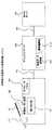
図1は、本発明の実施例1における画像処理システムの概略を示す構成図である。(Configuration of Example 1)
FIG. 1 is a configuration diagram showing an outline of an image processing system in
画像処理システムは、画像読み取り装置1と、この画像読み取り装置1にネットワークケーブル45を介して接続されたEmailサーバ50とを備えている。 The image processing system includes an
画像読み取り装置1は、複数枚載置された原稿2を順次1枚ずつ分離して搬送する原稿搬送手段(例えば、自動原稿送り部、以下「ADF」という。)11と、原稿2の読み取りタイミングを司る読み取り用センサ部12と、原稿2の画像を読み取る画像読み取り手段及び原稿2の画像を再度読み取る再画像読み取り手段(例えば、読み取り部)13と、この読み取り部13にて読み取った画像データを格納する随時読み書き可能なメモリ(以下「RAM」という。)等の格納部(例えば、画像データ記憶部)18と、ユーザに対して画像読み取り装置1の状態の表示及びユーザからの入力を受付けるオペレータパネル34と、画像データ記憶部18に格納された画像データを編集する編集手段(例えば、画像編集部)24等とを有している。オペレータパネル34は、搬送異常の報知手段及び搬送異常の表示手段としての機能も有している。 The
Emailサーバ50は、画像データ記憶部、通信部、及びサーバ全体をプログラム制御する中央処理装置(以下「CPU」という。)等により構成されている。 The
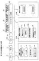
図2は、図1中の画像読み取り装置1を示す構成図である。
画像読み取り装置1は、内部バス3を有している。内部バス3には、原稿2の画像の読み取りを制御する画像入力部10と、装置全体をプログラム制御するCPU16と、プログラムを格納する読み出し専用メモリ(以下「ROM」という。)17と、画像入力部10にて読み取った画像データを格納する画像データ記憶部18と、画像入力部10にて読み取った画像データを外部装置(デバイス)へ出力してもよいか否か、即ち、原稿2の搬送異常の有無を検知して判定する検知手段としての機能を有する画像出力判定部20と、オペレータパネル34を制御するオペレータパネル制御部30と、画像出力判定部20により画像データが送信できると判定された場合にその画像データを外部デバイスへ出力する画像出力部40等とが接続されている。オペレータパネル制御部30には、編集入力画面表示制御部31と、読み取り結果確認画面表示制御部32と、各種オペレータパネル34を制御して表示及びユーザからの入力を監視する原稿枚数入力表示制御部33とが接続されている。FIG. 2 is a configuration diagram showing the
The
画像入力部10は、複数枚の原稿2を搬送するADF11と、原稿の搬送を監視する読み取り用のセンサ部12と、原稿2の画像を読み取る読み取り部13と、読み取った原稿2の枚数をカウントするカウント手段(例えば、読み取りカウンタ)14等とから構成されている。画像出力判定部20は、原稿枚数入力表示制御部33より通知されたユーザがこれから読み込む原稿2の枚数を保持する原稿カウンタ21と、編集入力画面表示制御部31からの編集指定により画像データ記憶部18に格納された画像データを編集する画像編集部24とを有している。更に、画像出力判定部20は、画像入力部10から読み込まれた画像データが画像データ記憶部18のどこに格納されているかを特定する画像データパスと、この画像データパスを画像出力判定部20で管理するための画像idとを有し、外部への出力準備用の画像データは、元画像id22として管理し、再読み取りして一時的に格納される画像データは、再読み取り画像id23として管理する構成になっている。 The
図3は、図2の画像読み取り装置1におけるカウンタ入力手段(例えば、読み取り原稿枚数入力画面)の表示例を示す図である。 FIG. 3 is a diagram showing a display example of counter input means (for example, a read document number input screen) in the
この図3では、ScanToEmailを実行する前に、ユーザに対して設定原稿枚数を入力させる読み取り原稿枚数入力画面51の表示例が示されている。読み取り原稿枚数入力画面51は、ユーザに読み取り原稿枚数の入力を促すメイン画面51aと、テンキー等の入力された原稿枚数を表示する原稿枚数表示部の入力ボタン51bと、ユーザからの開始指示を受付ける開始要求受付表示部の開始ボタン51cと、本機能の無効指示を受付ける無効要求受付表示部の無効ボタン51dとから構成されている。 FIG. 3 shows a display example of a read document
図4は、図2の画像読み取り装置1における読み取り結果確認画面の表示例を示す図である。 FIG. 4 is a diagram showing a display example of a reading result confirmation screen in the
この図4では、読み取り原稿枚数入力画面51でユーザにより入力された原稿枚数と実際に読込んだ原稿枚数が異なった際に表示する読み取り結果確認画面52の表示例が示されている。読み取り結果確認画面52は、ユーザに対して読み取り確認を促すメイン画面52aと、Email送信のキャンセルを受付けるキャンセルボタン52bと、Email送信の実行を受付けるオーケー(OK)ボタン52cと、読み取り結果の詳細表示を受付ける詳細確認ボタン52dとから構成され、搬送異常の報知手段及び搬送異常の表示手段としての機能も有している。 FIG. 4 shows a display example of a read result confirmation screen 52 displayed when the number of originals input by the user on the read original
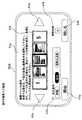
図5は、図2の画像読み取り装置1における編集情報入力手段(例えば、編集入力画面)の表示例を示す図である。 FIG. 5 is a diagram showing a display example of edit information input means (for example, edit input screen) in the
この図5では、読み取り結果確認画面52にて詳細確認ボタン52dが押下された際に表示する編集入力画面53の表示例が示されている。編集入力画面53は、ユーザにページ編集の案内を促すメイン画面53aと、読み取った画像イメージのサムネイルを表示するイメージ表示部53bと、読み取った画像データの表示を前にスクロールする左矢印キー53c、読み取った画像データの表示を後にスクロールする右矢印キー53dと、削除、追加及び追加&削除の編集条件を指定できる編集条件ボタン(即ち、加工条件ボタン)53eと、テンキー等から入力された読み取り済みの画像データ削除枚数を表示する削除枚数表示部の削除枚数ボタン53fと、編集条件及び削除枚数の条件で編集を開始する要求を受付ける開始ボタン53gと、本編集を何もせずに終了する閉じるボタン53hとから構成されている。 FIG. 5 shows a display example of the
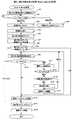
(図1、図2のScanToEmail処理)
図6は、図1及び図2の画像処理システムにおける読み取り処理(ScanToEmail処理)を示す概略のフローチャートである。(ScanToEmail processing in Fig. 1 and Fig. 2)
FIG. 6 is a schematic flowchart showing a reading process (ScanToEmail process) in the image processing system of FIGS. 1 and 2.
図1及び図2の画像読み取り装置1において、ユーザがオペレータパネル34によりScanToEmail処理を実行すると、オペレータパネル制御部30は、画像出力判定部20に対して、ScanToEmail処理が実行された旨を通知する。ScanToEmail処理が実行された旨を通知された画像出力判定部20は、オペレータパネル制御部30に対して図3の読み取り原稿枚数入力画面51を表示するように指示する。読み取り原稿枚数入力画面51を表示するよう指示されたオペレータパネル制御部30は、原稿枚数入力表示制御部33に対して図3の読み取り原稿枚数入力画面51を表示するように指示する。読み取り原稿枚数入力画面51を表示するように指示された原稿枚数入力表示制御部33は、オペレータパネル34に図3の原稿枚数入力画面51を表示する(ステップS1)。 In the
その後、原稿枚数入力表示制御部33は、ユーザからの原稿枚数表示部の原稿枚数入力ボタン51bによる入力と、開始要求受付表示部の開始ボタン51c又は無効要求受付表示部の無効ボタン51dによる入力を待つ(ステップS2)。 Thereafter, the document number input
原稿枚数入力表示制御部33は、開始ボタン51cが押されたことを検出すると、画像出力判定部20に対してユーザによる原稿枚数入力ボタン51bの入力のカウントと共に読み取り原稿枚数確認開始を指示する。読み取り原稿枚数確認開始を指示された画像出力判定部20は、原稿カウンタ21へ原稿枚数入力ボタン51bの入力値をセットする(ステップS3)。又、原稿枚数入力表示制御部33は、無効ボタン51dが押されたことを検出すると、画像出力判定部20に対して読み取り原稿枚数確認無効を指示する。読み取り原稿枚数確認無効を指示された画像出力判定部20は、原稿カウンタ21を0(ゼ口)にセットする(ステップS4)。 When the document number input
その後、画像出力判定部20は、画像入力部10に対して原稿読み取りを指示する。原稿読み取りが指示された画像入力部10は、ADF11、センサ部12、及び読み取り部13をコントロールして原稿を読み取る(ステップS5)。読み取った画像データは、画像データ記憶部18に格納する。又、それと並行して、画像入力部10は、センサ部12を監視して、センサ部13がオフ(OFF)からオン(ON)へ変化する毎に、読み取りカウンタ14をインクリメント(増分)して読み取り枚数をカウントさせる(ステップS6)。 Thereafter, the image
画像入力部10は、最終原稿の読み取りが完了したと判定すると、画像出力判定部20に対して、読み取りカウンタ14及び画像データ記憶部18に格納された画像データを特定するための画像データパスの情報と共に読み取り完了した旨を通知する。読み取り完了した旨を通知された画像出力判定部20は、画像idを生成して、生成した画像idと前記で渡された画像データパスの情報を関連付けるために元画像id22として格納した後、通知された読み取りカウンタ14のカウント値と原稿カウンタ21のカウント値とを比較する(ステップS8)。 When the
画像出力判定部20は、原稿カウンタ21が0(ゼロ)、又は、読み取りカウンタ14のカウント値と原稿カウンタ21のカウント値が一致していた場合(YES)、画像データ記憶部18のデータを読み出し、画像出力部40に対し出力要求して、画像データをメール送信させる(ステップS16)。画像出力判定部20は、画像データ記憶部18のデータが全て送信完了したと判定すると、読み取りカウンタ14をクリアし(ステップS17)、画像データ記憶部18に保持されている画像データを削除した後(ステップS18)、処理を終了する。 When the
画像出力判定部20は、ステップS8において読み取りカウンタ14のカウント値と原稿カウンタ21のカウント値とが不一致の場合(NO)、オペレータパネル制御部30に対して、図4の読み取り結果確認画面52を表示するように指示する。読み取り結果確認画面52を表示するように指示されたオペレータパネル制御部30は、読み取り結果確認画面表示制御部32に対して、読み取り結果確認画面52を表示するように指示する。読み取り結果確認画面52を表示するように指示された読み取り結果確認画面表示制御部32は、図4の読み取り結果確認画面52を表示する(ステップS9)。その後、読み取り結果確認画面表示制御部32は、ユーザからのキャンセルボタン52b、OKボタン52c、又は詳細確認ボタン52dの入力を待つ(ステップS10)。 When the count value of the reading
読み取り結果確認画面表示制御部32は、ステップS10において、キャンセルボタン52bが押されたことを検出すると、画像出力判定部20に対してキャンセルが指示された旨を通知する。キャンセルが指示された旨を受け取った画像出力判定部20は、読み取りカウンタ14をクリアし(ステップS17)、画像データ記憶部18に保持されている画像データを削除した後(ステップS18)、処理を終了する。 When the reading result confirmation screen
読み取り結果確認画面表示制御部32は、ステップS10において、OKボタン52cが押されたことを検出すると、画像出力判定部20に対して、画像データ送信が指示された旨を通知する。画像データ送信が指示された旨を受け取った画像出力判定部20は、画像データ記憶部18のデータを読み出し、画像出力部40に対し出力要求して、画像データをメール送信させる(ステップS16)。画像出力判定部20は、画像データ記憶部18のデータが全て送信完了したと判定すると、読み取りカウンタ14をクリアし(ステップS17)、画像データ記憶部18に保持されている画像データを削除した後(ステップS18)、処理を終了する。 When the reading result confirmation screen
又、読み取り結果確認画面表示制御部32は、ステップS10において、詳細確認ボタン52dが押されたことを検出すると、画像出力判定部20に対して、画像データ表示要求が指示された旨を通知する。画像データ表示要求が指示された旨を受け取った画像出力判定部20は、オペレータパネル制御部30に対して、前記元画像id22と共に編集入力画面を表示するように指示する。編集入力画面を表示するように指示されたオペレータパネル制御部30は、編集入力画面表示制御部31に対して、図5の編集入力画面53を表示するように指示する。編集入力画面53を表示するように指示された編集入力画面表示制御部31は、図5の編集入力画面53を表示する(ステップS11)。 When the reading result confirmation screen
その後、編集入力画面表示制御部31は、ユーザからの編集条件ボタン53e、表示スクロール指示の左矢印キー53c、右矢印キー53d、削除枚数表示部の削除枚数ボタン53f、開始ボタン53g、又は閉じるボタン53hの入力を待つ(ステップS12)。編集入力画面表示制御部31は、閉じるボタン53hが押されると、編集中断を画像出力判定部20へ通知する。編集中断を通知された画像出力判定部20は、オペレータパネル制御部30に対して、図4の読み取り結果確認画面52を表示するように指示する(ステップS9)。その後、前記ステップS10の処理に戻る。 After that, the edit input screen display control unit 31 displays an
編集入力画面表示制御部31は、ステップS12において、開始ボタン53gが押されると、ユーザから入力された編集条件及び編集対象ページ数、及び削除枚数と共に編集要求を画像出力判定部20へ通知する。編集要求を通知された画像出力判定部20は、編集条件として追加指定があるか否かを判定し(ステップS13)、追加要求があった場合、画像入力部10に対して画像読み取り指示をする(ステップS14)。その後、画像入力部10から画像読み取り完了した旨が通知されたら、画像出力判定部20は、画像idを生成して画像入力部10から渡された画像データパスと前記生成した画像idを関連付けるために再読み取り画像id23として格納し、前記編集入力画面表示制御部31から入手した編集条件に従って、画像データを編集するように画像編集部24へ指示する。画像編集部24は、画像データを編集するように指示された場合、又は、ステップS13において追加要求が無かった場合、画像データを編集し(ステップS15)、オペレータパネル制御部30に対して図4の読み取り結果確認画面52を表示するように指示する(ステップS9)。その後、前記ステップS9の処理に戻る。 When the
(図6中の編集入力画面表示処理(ステップS11))
図7は、図6中の編集入力画面表示処理(ステップS11)を示すフローチャートである。(Edit input screen display process in FIG. 6 (step S11))
FIG. 7 is a flowchart showing the edit input screen display process (step S11) in FIG.
編集入力画面表示制御部31は、編集入力画面表示処理を開始し、図5の編集入力画面53のイメージ表示部53bに表示可能なイメージを表示サイズ、表示解像度、及び画像出力判定部20から渡された元画像id22を指定し、画像編集部24に対して取得要求をする(ステップS21)。即ち、編集入力画面表示制御部31は、画像データを画像編集部24より読み出し、表示イメージを生成する。編集入力画面表示制御部31は、画像編集部24が表示イメージを入手すると、イメージ表示部53bに取得したイメージを表示する(ステップ22)。その後、ユーザからのスクロール要求の左矢印キー53c、右矢印キー53d、編集条件ボタン53e、削除枚数ボタン53f、開始ボタン53g、又は閉じるボタン53hの入力を待ち、ユーザの入力を監視する(ステップ23)。 The edit input screen display control unit 31 starts the edit input screen display process, and transfers an image that can be displayed on the
編集入力画面表示制御部31は、ユーザからの入力が閉じるボタン53hであるか否かをチェックし(ステップS24)、閉じるボタンであった場合(YES)、編集中断を画像出力判定部20へ通知し、処理を終了する。閉じるボタンでなかった場合(NO)、編集入力画面表示制御部31は、ユーザからの入力が、開始ボタン53gであるか否かチェックする(ステップS25)。開始ボタン53gであった場合(YES)、編集入力画面表示制御部31は、選択されているイメージ、加工条件及び削除枚数により編集情報を生成して格納し、ユーザから入力された編集条件及び編集対象ページ数、及び削除枚数と共に、編集要求として画像出力判定部20へ通知し(ステップS26)、処理を終了する。 The edit input screen display control unit 31 checks whether or not the input from the user is the
ステップS25において、開始ボタン53gでなかった場合(NO)、編集入力画面表示制御部31は、ユーザからの入力が左矢印キー53cであるか否かをチェックし(ステップS27)、左矢印キー53cであった場合(YES)、編集入力画面53のイメージ表示部53bに表示されている前の画面イメージを画像編集部24から取得要求し(ステップS28)、表示されているイメージを1ページ分左にシフトして、取得した表示イメージを編集入力画面53のイメージ表示部53bの最も左に挿入し、表示イメージを更新して(ステップS35)、ユーザ入力監視処理(ステップS23)に戻る。 If it is not the
ステップS27において、左矢印キー53cでなかった場合(NO)、ユーザからの入力が右矢印キー53dであるか否かをチェックする(ステップS29)。右矢印キー53cであった場合(YES)、編集入力画面表示制御部31は、編集入力画面53のイメージ表示部53bに表示されている後のイメージを画像編集部24から取得要求し(ステップS30)、表示されているイメージを1ページ分右にシフトして、取得した表示イメージを編集入力画面53のイメージ表示部53bの最も右に挿入し、表示イメージを更新して(ステップ35)、ユーザ入力監視処理(ステップS23)に戻る。 If it is not the left arrow key 53c in step S27 (NO), it is checked whether or not the input from the user is the
ステップS29において、右矢印キー53dでなかった場合(NO)、ユーザからの入力が編集条件ボタン(即ち、加工条件ボタン)53e中の加工条件キーであるか否かをチェックする(ステップS31)。加工条件キーであった場合(YES)、編集入力画面表示制御部31は、選択された加工条件の表示をハイライトし(明るくし)(ステップS32)、表示を更新して(ステップS35)、ユーザ入力監視処理(ステップS23)に戻る。 If it is not the
ステップS31において、加工条件でなかった場合(NO)、編集入力画面表示制御部31は、ユーザからの入力が、編集条件ボタン(即ち、加工条件ボタン)53e中の削除枚数キーであるか否かをチェックする(ステップS33)。削除枚数キーであった場合(YES)、編集入力画面表示制御部31は、削除枚数ボタン53fの削除カウンタ情報を更新し(ステップS34)、表示を更新して(ステップS34)、ユーザ入力監視処理(ステップS23)に戻る。 In step S31, when the processing condition is not satisfied (NO), the edit input screen display control unit 31 determines whether or not the input from the user is a deletion number key in the edit condition button (that is, the process condition button) 53e. Is checked (step S33). If it is the delete number key (YES), the edit input screen display control unit 31 updates the delete counter information of the
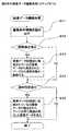
(図6中の画像データ編集処理(ステップS15))
図8は、図6中の画像データ編集処理(ステップS15)を示すフローチャートである。(Image data editing process in FIG. 6 (step S15))
FIG. 8 is a flowchart showing the image data editing process (step S15) in FIG.
画像編集部24は、画像データ編集処理(ステップS15)において、先ず、編集入力画面表示制御部31より通知された編集条件及び編集対象ページ数、削除枚数を入手する(ステップS41)。画像編集部24は、編集入力画面表示制御部31より通知された編集条件として削除指定があるか否かをチェックし(ステップS42)、削除指定があった場合(YES)、編集対象ページと削除枚数を元に、画像データ記憶部18に格納された元画像データから、指定されたページから指定枚数分の画像イメージを削除し(ステップS43)、ステップS44へ進む。ステップS42において、削除指定がなかった場合(NO)、ステップS44へ進む。 In the image data editing process (step S15), the
ステップS44において、画像編集部24は、編集入力画面表示制御部31より通知された編集条件として追加指定があるか否かをチェックする(ステップS44)。追加指定があった場合(YES)、画像編集部24は、編集対象ページを元に、再読み取り画像id23に基づき再読み取りした画像データを特定し、元画像id22に基づき元画像データを特定して元画像データを編集し、処理を終了する。即ち、画像データ記憶部18に格納された元画像データの指定されたページの所に再読み取りした画像データを挿入し(ステップS45)、処理を終了する。ステップS44において、追加指定がなかった場合(NO)、そのまま処理を終了する。 In step S44, the
(実施例1の効果)
本実施例1によれば、ユーザが図3の読み取り原稿枚数入力画面51で入力した原稿枚数(即ち、ユーザが意図した原稿枚数)より少ない場合に、読み取り結果確認画面52にてユーザに確認させて、未読み取り原稿(即ち、未スキャン)のもののみを再セットした上でスキャンを行い、この再スキャンした画像を、図5の編集入力画面53にて編集(例えば、適当な位置に追加等)して出力する構成にしている。そのため、ScanToEmail等、読み取り原稿2が重送した場合、ユーザが、重送した原稿2を特定してこの原稿2のみを再読み取りしてEmail送信できるので、読み取りに要する時間を短縮できる。(Effect of Example 1)
According to the first embodiment, when the number of documents input by the user on the read document
(実施例2の構成)
図9は、本発明の実施例2における画像読み取り装置1Aを示す構成図であり、実施例1を示す図2中の要素と共通の要素には共通の符号が付されている。(Configuration of Example 2)
FIG. 9 is a configuration diagram illustrating an image reading apparatus 1A according to the second embodiment of the present invention. Elements common to those in FIG. 2 illustrating the first embodiment are denoted by common reference numerals.
本実施例2の画像読み取り装置1Aは、図1に示す実施例1の画像処理システムにおいて画像読み取り装置1に代えて設けられる装置である。本実施例2の画像読み取り装置1Aでは、実施例1とは異なる構成の画像入力部10Aと、実施例1と同様のCPU16、ROM17、及び画像データ記憶部18と、実施例1とは異なる構成の画像出力判定部20Aと、実施例1と同様のオペレータパネル制御部30、画像入力画面表示制御部31、読み取り結果確認画面表示制御部32、原稿枚数入力表示制御部33、オペレータパネル34、及び画像出力部40とを備えている。 An image reading apparatus 1A according to the second embodiment is an apparatus provided in place of the
本実施例2の画像入力部10Aでは、実施例1の画像入力部10に対して、重送検出手段(例えば、重送監視部)15が追加されている。重送監視部15は、原稿2が重送したか否かを検出(監視)するものである。更に、本実施例2の画像出力判定部20Aでは、実施例1の画像出力判定部20に対して、重送情報25が追加されている。その他の構成は、実施例1と同様である。 In the
図10は、図9の画像読み取り装置1Aにおける編集入力画面の表示例を示す図であり、実施例1を示す図5中の要素と共通の要素には共通の符号が付されている。 FIG. 10 is a diagram showing a display example of the edit input screen in the image reading apparatus 1A of FIG. 9, and common elements to those in FIG.
本実施例2の編集入力画面53Aでは、実施例1の編集入力画面53におけるイメージ表示部53bに代えて、これとは異なるイメージ表示部53iを有している。イメージ表示部53iでは、重送と検出した原稿ページを強調して表示する表示手段としての機能を有する点が、実施例1のイメージ表示部53と異なる。その他の構成は、実施例1と同様である。 The
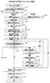
(図9のScanToEmail処理)
図11は、図9の画像読み取り装置1Aにおける読み取り処理(ScanToEmail処理)を示す概略のフローチャートであり、実施例1を示す図6中の要素と共通の要素には共通の符号が付されている。(ScanToEmail processing in Fig. 9)
FIG. 11 is a schematic flowchart showing a reading process (ScanToEmail process) in the image reading apparatus 1A of FIG. 9. Elements common to the elements in FIG. 6 showing the first embodiment are denoted by common reference numerals. .
図11のフローチャートでは、図6のフローチャートに対して、読み取り枚数をカウントする処理(ステップS6)と、読み取りカウンタ14と原稿カウンタ21を比較する処理(ステップS7)との間に、重送監視部15の処理(ステップS41,S42)が追加され、更に、図6の編集入力画面表示処理(ステップS11)に代えて、これとは異なる編集入力画面表示処理(ステップS43)が設けられている。その他の処理は、実施例1と同様であるので、以下、実施例1とは異なる処理について説明する。 In the flowchart of FIG. 11, compared with the flowchart of FIG. 6, a double feed monitoring unit is provided between the process of counting the number of read sheets (step S6) and the process of comparing the reading
ScanToEmail処理において、読み取り枚数をカウントする処理(ステップS6)が行われた後、重送監視部15では、センサ部12のON継続時間を監視して、重送したか否かを監視(即ち、読み取り原稿指定サイズよりも例えば5%以上長くONしたか否かをチェック)する(ステップS41)。重送監視部15は、そのチェック結果として読み取り原稿指定サイズよりも5%以上長くONしたと判定した場合(YES)、画像出力判定部20Aに対して、読み取りカウンタ14の値を重送情報25として送信し(ステップS42)、読み取りカウンタ14の値と原稿カウンタ21の値を比較する処理(ステップS7)へ進む。ステップS41において、読み取り原稿指定サイズよりも5%以上長くONしなかったと判定した場合(NO)、ステップS7へ進む。 In the ScanToEmail process, after the process of counting the number of read sheets (step S6) is performed, the double
実施例1と同様のステップS7〜S10の処理が行われる。読み取り結果確認画面表示制御部32は、ステップS10において、図4の詳細確認ボタン52dが押されたことを検出すると、画像出力判定部20Aに対して、画像データ表示要求が指示された旨を通知する。画像データ表示要求が指示された旨を受け取った画像出力判定部20Aは、オペレータパネル制御部30に対して、前記元画像id22と共に編集入力画面を表示するように指示する。編集入力画面を表示するように指示されたオペレータパネル制御部30は、編集入力画面表示制御部31に対して、図10の編集入力画面53Aを表示するように指示する。編集入力画面53Aを表示するように指示された編集入力画面表示制御部31は、図10の編集入力画面53Aを表示する(ステップS43)。その後は、実施例1と同様の処理が行われる。 Steps S7 to S10 similar to those in the first embodiment are performed. When the reading result confirmation screen
(図11中の編集入力画面表示処理(ステップS43))
図12は、図11中の編集入力画面表示処理(ステップS43)を示すフローチャートであり、実施例1を示す図7中の要素と共通の要素には共通の符号が付されている。(Edit input screen display process in FIG. 11 (step S43))
FIG. 12 is a flowchart showing the edit input screen display process (step S43) in FIG. 11. Elements common to the elements in FIG. 7 showing the first embodiment are denoted by common reference numerals.
図12のフローチャートでは、図7のフローチャートにおけるステップS21の処理に代えて、ステップS51,S52の処理が行われる。その他の処理は、実施例1と同様であるので、以下、実施例1とは異なる処理について説明する。 In the flowchart of FIG. 12, processes of steps S51 and S52 are performed instead of the process of step S21 in the flowchart of FIG. Since other processes are the same as those in the first embodiment, processes different from those in the first embodiment will be described below.
編集入力画面表示制御都31は、編集入力画面表示処理を開始し、重送監視部15より通知された重送情報25を画像出力判定部20Aより取得し(ステップS51)、ステップS52へ進む。ステップS52において、編集入力画面表示制御部31は、重送情報25から画像編集部24に対して重送したと特定された原稿の周辺の画像イメージを取得し、図10の編集入力画面53A中のイメージ表示部53iに示すように、重送したと特定された原稿を強調して表示する。即ち、編集入力画面表示制御部31は、重送と検出したページの前後の画像データを画像編集部24より読み出し、表示イメージを生成する。その後、実施例1と同様のステップS22〜S35の処理が行われる。 The edit input screen display control capital 31 starts the edit input screen display process, acquires the double feed information 25 notified from the double
(実施例2の効果)
本実施例2によれば、重送監視部15によって重送した個所を特定し、編集入力画面53A中のイメージ表示部53iに強調して表示する構成にしたので、実施例1に比べ、ユーザが、重送した原稿の箇所を探す時間を極力減らすことができる。(Effect of Example 2)
According to the second embodiment, the multifeed section is specified by the
(実施例3の構成)
図13は、本発明の実施例3における画像処理システムの概略を示す構成図であり、実施例1を示す図1中の要素と共通の要素には共通の符号が付されている。(Configuration of Example 3)
FIG. 13 is a configuration diagram illustrating an outline of an image processing system according to the third embodiment of the present invention. Elements common to the elements in FIG. 1 illustrating the first embodiment are denoted by common reference numerals.
本実施例3の画像処理システムでは、実施例1の画像読み取り装置1とは異なる構成の画像読み取り装置1Bと、この画像読み取り装置1Bにネットワークケーブル45を介して接続された画像処理手段(例えば、ドキュメントサーバ)60と、このドキュメントサーバ60にネットワークケーブル46を介して接続された実施例1と同様のEmailサーバ50とを備えている。 In the image processing system according to the third embodiment, an
本実施例3の画像読み取り装置1Bは、実施例1の画像読み取り装置1における画像データ記憶部18及び画像編集部24が設けられていない点等が実施例1と異なる。 The
ドキュメントサーバ60は、画像読み取り装置1Bで読み取られた画像データを格納する格納部(例えば、画像データ記憶部)66、及びこの画像データ記憶部66に格納された画像データを編集する編集手段(例えば、画像編集部)67c等を有している。 The
図14は、図13中の画像読み取り装置1Bを示す構成図であり、実施例1を示す図2中の要素と共通の要素には共通の符号が付されている。 FIG. 14 is a block diagram showing the
本実施例3の画像読み取り装置1Bは、実施例1と同様に原稿2の読み取りを制御する画像入力部10と、実施例1と同様のCPU16及びROM17と、実施例1の画像データ記憶部18とは異なる随時読み書き可能なメモリ(以下「RAM」という。)18Bと、実施例1の画像出力判定部20とは異なる構成の画像出力判定部20Bと、実施例1と同様にオペレータパネル34を制御するオペレータパネル制御部30、編集入力画面表示制御部31、読み取り結果確認画面表示制御部32、各種オペレータパネル34を制御して表示及びユーザからの入力を監視する原稿枚数入力表示制御部33、及びオペレータパネル34と、実施例1の画像出力部40とは異なる構成の画像データの転送手段(例えば、画像送受信部)40Bとを有し、これらが、実施例1と同様の内部バス3によって相互に接続されている。 The
画像出力判定部20Bは、画像入力部10にて読み取った画像データをEmailサーバ50へ出力してもよいか否か、即ち、原稿2の搬送異常の有無を検知して判定する検知手段としての機能等を持ち、実施例1と同様の原稿カウンタ21と、実施例1とほぼ同様に管理される元画像id22B及び再読み取り画像id23Bと、実施例1に対して追加された画像制御コマンド生成部26とを有している。 The image
原稿カウンタ21は、原稿枚数入力表示制御部33より通知されたユーザがこれから読み込む原稿2の枚数を保持するカウンタである。画像出力判定部20Bは、画像入力部10から読み込まれた画像データがドキュメントサーバ60内の画像データ記憶部65のどこに格納されているかを特定する画像idを有し、Emailサーバ50への出力準備用の画像データは、元画像id22Bとして管理されると共に、再読み取りして一時的に格納される画像データは、再読み取り画像id23Bとして管理される。画像制御コマンド生成部26は、編集入力画面表示制御部31からの編集指定により、ドキュメントサーバ60内の画像編集部67cに対してコマンドを発行するものであり、編集情報をドキュメントサーバ60へ通知する通知手段としての機能も有している。 The
画像送受信部40Bは、コマンド及び画像データのやり取りを実施するものであり、ドコマンド及び画像データをキュメントサーバ60へ出力する送信制御部41と、ドキュメントサーバ60から画像データを取得する受信制御部42等とを有している。 The image transmission /
図15は、図13中のドキュメントサーバ60を示す構成図である。
ドキュメントサーバ60は、内部バス61を有している。この内部バス61には、サーバ全体をプログラム制御するCPU62と、プラグラム格納用のROM63と、ワーキングデータ格納用のRAM64と、画像読み取り装置1Bからコマンドもしくは画像データを受信、送信する画像入出力部65と、画像読み取り装置1Bから受信した画像データを格納する画像データ記憶部66と、画像読み取り装置1Bからのコマンドを解析するコマンド解析部67と、画像データ記憶部66のデータをEmailサーバ50へ送信する出力手段(例えば、画像データ送信部)68とが接続されている。FIG. 15 is a block diagram showing the
The
画像入出力部65は、画像読み取り装置1Bからのコマンド及び画像データを受信する入力制御部65aと、画像データを画像読み取り装置1Bへ送信する返信部(例えば、出力制御部)65b等とを有している。 The image input /
コマンド解析部67は、画像読み取り装置1Bから送信された画像idと画像データ記憶部66に格納された画像データの関係を管理する元画像id67a,67bと画像データパスとから成る複数の画像データ管理情報と、画像読み取り装置1Bからの画像編集指示を受付けて画像データ記憶部66に格納された画像データを編集する画像編集部67c等とから構成されている。 The
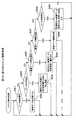
(図13、図14のScanToEmail処理)
図16は、図13及び図14の画像処理システムにおける読み取り処理(ScanToEmail処理)を示す概略のフローチャートであり、実施例1を示す図6中の要素と共通の要素には共通の符号が付されている。(ScanToEmail processing in FIGS. 13 and 14)
FIG. 16 is a schematic flowchart showing a reading process (ScanToEmail process) in the image processing system shown in FIGS. 13 and 14. Elements common to those shown in FIG. ing.
本実施例3の図16のフローチャートでは、実施例1の図6のフローチャートに対してステップS61〜S66の処理が異なる。 In the flowchart of FIG. 16 of the third embodiment, the processes in steps S61 to S66 are different from the flowchart of FIG. 6 of the first embodiment.
図13及び図14の画像読み取り装置1Bにおいて、ユーザがオペレータパネル34によりScanToEmail処理を実行すると、実施例1と同様のステップS1〜S4の処理が行われ、ステップS61へ進む。 In the
ステップS61において、画像出力判定部20Bは、元画像データとして取り扱うために画像id情報を生成して元画像id22Bとして保持し、画像入力部10に対して原稿読み取りを指示する。原稿読み取りを指示された画像入力部10は、ADF11、センサ部12、及び読み取り部13を制御して原稿2を読み取る。読み取った画像データは、画像出力判定部20Bにより元画像id22Bを付加し、データ送信指示コマンドとして画像送受信部40Bからドキュメントサーバ60へ送信する。 In step S61, the image
送信後、実施例1と同様に、ステップS6〜S10の処理が行われ、ステップS62へ進む。 After the transmission, the processes of steps S6 to S10 are performed as in the first embodiment, and the process proceeds to step S62.
ステップS62において、実施例1とほぼ同様に、読み取り結果確認画面表示制御部32は、ステップS10にて図4の詳細確認ボタン52dが押されたことを検出すると、画像出力判定部20Bに対して、画像データ表示要求が指示された旨を通知する。画像データ表示要求が指示された旨を受け取った画像出力判定部20Bは、オペレータパネル制御部30に対して、元画像id22Bと共に編集入力画面を表示するように指示する。編集入力画面を表示するように指示されたオペレータパネル制御部30は、編集入力画面表示制御部31に対して、図5の編集入力画面53を表示するように指示する。編集入力画面53を表示するように指示された編集入力画面表示制御部31は、図5の編集入力画面53を表示し、ステップS12へ進む。 In step S62, in substantially the same manner as in the first embodiment, when the reading result confirmation screen
ステップS12において、図5の編集入力画面53にてユーザの入力を待ち(即ち、開始ボタン53g又は閉じるボタン53hの押下を待ち)、開始ボタン53gが押下されると、ステップS13へ進む。ステップS13において、実施例1とほぼ同様に、編集要求を通知された画像出力判定部20Bは、編集条件として追加指定があるか否かを判定し、追加要求があった場合はステップS63へ進み、追加要求がなかった場合はステップS64へ進む。 In step S12, the user waits for input by the user on the
ステップS63において、画像出力判定部20Bは、再読み取りデータとして取り扱うために画像id情報を生成して再読み取り画像id23Bとして保持し、画像入力部10に対して原稿読み取りの指示をする。原稿読み取りの指示がされた画像入力部10は、ADF11、センサ部12、及び読み取り部13を制御して原稿2を読み取る。読み取った画像データは、画像出力判定部20Bにより再読み取り画像id23Bを付加して、データ送信指示コマンドとして画像送受信部40Bからドキュメントサーバ60へ送信し、ステップS64へ進む。 In step S <b> 63, the image
ステップS64において、画像出力判定部20Bは、編集入力画面表示制御部31から入手した編集条件と元画像id22B及び再読み取り画像id23Bを、画像送受信部40Bを介してドキュメントサーバ60へ、画像データ編集指示コマンドとして送信する。送信後、実施例1と同様に、ステップS9,S10の処理へ戻る。ステップS10において、図4の読み取り結果確認画面52にてユーザの入力を待ち(即ち、図4のキャンセルボタン52b又はOKボタン52cの押下を待ち)、OKボタン52cが押下されると、ステップS65進み、キャンセルボタン52bが押下されると、ステップS17へ進む。 In step S64, the image
ステップS65において、画像出力判定部20Bは、画像送受信部40Bを介して、メールサーバ60への送信指示コマンドをドキュメントサーバ60へ送信し、ステップS17へ進む。ステップS17において、実施例1とほぼ同様に、画像出力判定部20Bは、読み取りカウンタ14をクリアし、ステップS66へ進む。 In step S65, the image
ステップS66において、画像出力判定部20Bは、画像送受信部40Bを介して、元画像id22B及び再読み取り画像id23Bをドキュメントサーバ60へ、画像データ削除指示コマンドとして送信し、処理を終了する。 In step S66, the image
(図16中の編集入力画面表示処理(ステップS62))
図17は、図16中の編集入力画面表示処理(ステップS62)を示すフローチャートであり、実施例1を示す図7中の要素と共通の要素には共通の符号が付されている。(Edit input screen display process in FIG. 16 (step S62))
FIG. 17 is a flowchart showing the edit input screen display process (step S62) in FIG. 16. Elements common to the elements in FIG. 7 showing the first embodiment are denoted by common reference numerals.
本実施例3の図17のフローチャートでは、実施例1の図7のフローチャートに対してステップS71〜S73の処理が異なる。 In the flowchart of FIG. 17 of the third embodiment, the processes of steps S71 to S73 are different from those of the flowchart of FIG.
編集入力画面表示制御部31は、編集入力画面表示処理を開始すると、ステップS71において、図5の編集入力画面53のイメージ表示部53bに表示可能なイメージを表示サイズ、表示解像度、及び画像出力判定部20Bから渡された元画像id22Bを指定し、画像制御コマンド生成部26に対して、画像イメージの取得を要求する。画像イメージの取得を要求された画像制御コマンド生成部26は、画像送受信部40Bを介して、ドキュメントサーバ60に対し、画像データ受信指示コマンドを発行し、該当の画像イメージを取得して編集入力画面表示制御部31へ渡す。即ち、ステップS71において、読み取った画像データをドキュメントサーバ60より読み出し、図5の編集入力画面53のイメージ表示部53bに表示できるサイズに編集し、ステップS22へ進む。 When the edit input screen display control unit 31 starts the edit input screen display process, the display size, display resolution, and image output determination of an image that can be displayed on the
ステップS22において、実施例1とほぼ同様に、編集入力画面表示制御部31は、画像制御コマンド生成部26が表示イメージを入手すると、イメージ表示部53bに取得したイメージを表示する。その後、実施例1と同様のステップS24〜S27の処理が行われ、このステップS27において、図5の編集入力画面53中の左矢印キー53cが押下された場合には(YES)、ステップS72へ進み、左矢印キー53cが押下されていない場合には(NO)、ステップS29へ進む。 In step S22, the edit input screen display control unit 31 displays the acquired image on the
ステップS72において、ステップS71と同様に、編集入力画面表示制御部31は、画像制御コマンド生成部26を経由してドキュメントサーバ60から、図5の編集入力画面53中のイメージ表示部53bに表示している前の画像データを取得し、ステップS35へ進む。即ち、イメージ表示部53bに表示している前の画像データをドキュメントサーバ60より読み出し、イメージ表示部53bに表示できるサイズに編集し、ステップS35へ進む。 In step S72, as in step S71, the edit input screen display control unit 31 displays the image from the
ステップS35において、実施例1と同様に、図5の編集入力画面53中のイメージ表示部53bに対し、編集入力画面の更新を指示し、ステップS24の処理に戻る。ステップS29において、図5の編集入力画面53中の右矢印キー53dが押下された場合には(YES)、ステップS73へ進み、右矢印キー53dが押下されていない場合には(NO)、ステップS31へ進む。 In step S35, as in the first embodiment, the
ステップS73において、ステップS71と同様に、編集入力画面表示制御部31は、画像制御コマンド生成部26を経由してドキュメントサーバ60から、表示している後の画像データを読み出し、イメージ表示部53bに表示できるサイズに編集し、ステップS35へ進む。 In step S73, as in step S71, the edit input screen display control unit 31 reads the displayed image data from the
ステップS29の後のステップS31〜S35までは、実施例1と同様の処理が行われる。 Processes similar to those in the first embodiment are performed from step S31 to step S35 after step S29.
(ドキュメントサーバのコマンド解析処理)
図18は、図13及び図15のドキュメントサーバ60におけるコマンド解析処理を示すフローチャートである。(Document server command analysis processing)
FIG. 18 is a flowchart showing command analysis processing in the
ドキュメントサーバ60は、コマンド解析処理を開始すると、コマンド解析部67が、画像読み取り装置1Bから画像データ削除指示コマンドの通知があったか否かをチェックし(ステップS81)、画像データ削除指示コマンドの通知があった場合(YES)、通知された画像id情報から、画像データ記憶部66に格納されている画像データを特定して削除し(ステップS82)、ステップS81の処理へ戻る。 When the
ステップS81において、画像データ削除指示コマンドの通知がなかった場合(NO)、コマンド解析部67は、画像読み取り装置1Bから画像データ送信指示コマンドの通知があったか否かをチェックし(ステップS83)、画像データ送信指示コマンドの通知があった場合(YES)、通知された画像id情報とページオフセット情報から、画像データ記憶部66に格納されている画像イメージを特定して、画像データ記憶部66から読み出し、画像読み取り装置1Bへ送信し(ステップS84)、ステップS81の処理へ戻る。 In step S81, when there is no notification of the image data deletion instruction command (NO), the
ステップS83において、画像データ送信指示コマンドの通知がなかった場合(NO)、コマンド解析部67は、画像読み取り装置1Bから画像データ受信指示コマンドの通知があったか否かをチェックし(ステップS85)、画像データ受信指示コマンドの通知があった場合(YES)、通知された画像id情報と、画像データ記憶部66に格納する画像データパスを管理して、送信された画像データを画像データ記憶部66へ書き込み(ステップS86)、ステップS81の処理へ戻る。 If there is no notification of the image data transmission instruction command in step S83 (NO), the
ステップS85において、画像データ受信指示コマンドの通知がなかった場合(NO)、コマンド解析部67は、画像読み取り装置1Bから画像データ編集指示コマンドの通知があったか否かをチェックし(ステップS87)、画像データ編集指示コマンドの通知があった場合(YES)、通知された元画像id22B、再読み取り画像id23B及び編集条件から、画像データ記憶部66に格納されている画像データを読み出して画像を編集する(ステップS88)。この画像編集では、実施例1の図8とほぼ同様の処理が行われ、編集後、ステップS81の処理へ戻る。 In step S85, when there is no notification of the image data reception instruction command (NO), the
ステップS87において、画像データ編集指示コマンドの通知がなかった場合(NO)、コマンド解析部67は、画像読み取り装置1Bからメール送信指示コマンドの通知があった否かをチェックし(ステップS89)、メール送信指示コマンドの通知があった場合(YES)、通知された画像id情報から、画像データ記憶部66に格納されている画像データを読み出し、画像データ送信部68からEmailサーバ50へ送信し(ステップS90)、ステップS81の処理へ戻る。 In step S87, when there is no notification of the image data editing instruction command (NO), the
(実施例3の効果)
本実施例3によれば、画像データ記憶部66をドキュメントサーバ60で保有しているので、画像読み取り装置1Bに大容量な記憶部が必要なくなり、画像読み取り装置1Bの回路規模を縮小してコストを抑えることが期待できる。(Effect of Example 3)
According to the third embodiment, since the image
(実施例4の構成)
図19は、本発明の実施例4における画像処理システムの概略を示す構成図であり、実施例1及び実施例3を示す図1及び図13中の要素と共通の要素には共通の符号が付されている。(Configuration of Example 4)
FIG. 19 is a configuration diagram illustrating an outline of an image processing system according to the fourth embodiment of the present invention. Elements common to the elements in FIGS. 1 and 13 illustrating the first and third embodiments are denoted by common reference numerals. It is attached.
本実施例4の画像処理システムでは、実施例3と同様の画像読み取り装置1Bと、この画像読み取り装置1Bにネットワークケーブル45を介して接続された画像形成装置70とを備えている。 The image processing system according to the fourth embodiment includes an
画像形成装置70は、画像読み取り装置1Bで読み取られた画像データを格納する格納部(例えば、画像データ記憶部)76、画像データを編集する編集手段(例えば、画像編集部)77c、及び画像データを印刷する画像形成部78b等を有している。 The
図20は、図19中の画像形成装置70を示す構成図である。
画像形成装置70は、内部バス71を有している。この内部バス71には、装置全体をプログラム制御するCPU72と、プログラム格納用のROM73と、ワーキングデータ格納用のRAM74と、画像読み取り装置1Bからコマンドもしくは画像データを受信、送信する画像送受信部75と、この画像送受信部75により受信した画像データを格納する画像データ記憶部76と、画像送受信部75により受信したコマンドを解析するコマンド解析部77と、画像データ記憶部76に格納された画像データを印刷媒体(例えば、用紙)に印刷して出力する出力手段(例えば、画像出力部)78とが接続されている。FIG. 20 is a block diagram showing the
The
画像送受信部75は、画像読み取り装置1Bからのコマンド及び画像データを受信する受信制御部75aと、画像データを画像読み取り装置1Bへ送信する返信部(例えば、送信制御部)75b等とを有している。 The image transmission /
コマンド解析部77は、画像読み取り装置1Bから送信された画像idと画像データ記憶部76に格納された画像データの関係を管理する元画像id77a,77bと画像データパスとから成る複数の画像データ管理情報と、画像読み取り装置1Bからの画像編集指示を受付けて画像データ記憶部76に格納された画像データを編集する画像編集部77c等とから構成されている。 The
画像出力部78は、画像データ記憶部76に格納された画像データを印刷可能なデータに変換する画像形成データ変換部78aと、この画像形成データ変換部78aで変換されたデータを用紙へ印刷する画像形成部78b等とを有している。 The
(図19、図20のScanToEmail処理)
図21は、図19及び図20の画像処理システムにおける読み取り処理(ScanToEmail処理)を示す概略のフローチャートであり、実施例1を示す図6中の要素と共通の要素には共通の符号が付されている。(ScanToEmail processing in FIGS. 19 and 20)
FIG. 21 is a schematic flowchart showing a reading process (ScanToEmail process) in the image processing system of FIGS. 19 and 20, and elements common to those in FIG. 6 showing the first embodiment are denoted by common reference numerals. ing.
本実施例4の図21のフローチャートでは、実施例1の図6のフローチャートに対してステップS91〜S96の処理が異なる。 In the flowchart of FIG. 21 of the fourth embodiment, the processes of steps S91 to S96 are different from those of the flowchart of FIG. 6 of the first embodiment.
図19及び図20の画像読み取り装置1Bにおいて、ユーザがオペレータパネル34によりScanToEmail処理を実行すると、実施例1と同様のステップS1〜S4の処理が行われ、ステップS91へ進む。 In the
ステップS91において、画像出力判定部20Bは、元画像データとして取り扱うために画像id情報を生成して元画像id22Bとして保持し、画像入力部10に対して原稿読み取りを指示する。原稿読み取りを指示された画像入力部10は、ADF11、センサ部12、及び読み取り部13を制御して原稿2を読み取る。読み取った画像データは、画像出力判定部20Bにより元画像id22Bを付加し、データ送信指示コマンドとして画像送受信部40Bから画像形成装置70へ送信する。 In step S91, the image
送信後、実施例1と同様に、ステップS6〜S10の処理が行われ、ステップS92へ進む。 After the transmission, the processes of steps S6 to S10 are performed as in the first embodiment, and the process proceeds to step S92.
ステップS92において、実施例1とほぼ同様に、読み取り結果確認画面表示制御部32は、ステップS10にて図4の詳細確認ボタン52dが押されたことを検出すると、画像出力判定部20Bに対して、画像データ表示要求が指示された旨を通知する。画像データ表示要求が指示された旨を受け取った画像出力判定部20Bは、オペレータパネル制御部30に対して、元画像id22Bと共に編集入力画面を表示するように指示する。編集入力画面を表示するように指示されたオペレータパネル制御部30は、編集入力画面表示制御部31に対して、図5の編集入力画面53を表示するように指示する。編集入力画面53を表示するように指示された編集入力画面表示制御部31は、図5の編集入力画面53を表示し、ステップS12へ進む。 In step S92, in substantially the same manner as in the first embodiment, when the reading result confirmation screen
ステップS12において、図5の編集入力画面53にてユーザの入力を待ち(即ち、開始ボタン53g又は閉じるボタン53hの押下を待ち)、開始ボタン53gが押下されると、ステップS13へ進む。ステップS13において、実施例1とほぼ同様に、編集要求を通知された画像出力判定部20Bは、編集条件として追加指定があるか否かを判定し、追加要求があった場合はステップS93へ進み、追加要求がなかった場合はステップS94へ進む。 In step S12, the user waits for input by the user on the
ステップS93において、画像出力判定部20Bは、再読み取りデータとして取り扱うために画像id情報を生成して再読み取り画像id23Bとして保持し、画像入力部10に対して原稿読み取りの指示をする。原稿読み取りの指示がされた画像入力部10は、ADF11、センサ部12、及び読み取り部13を制御して原稿2を読み取る。読み取った画像データは、画像出力判定部20Bにより再読み取り画像id23Bを付加して、データ送信指示コマンドとして画像送受信部40Bから画像形成装置70へ送信し、ステップS94へ進む。 In step S <b> 93, the image
ステップS94において、画像出力判定部20Bは、編集入力画面表示制御部31から入手した編集条件と元画像id22B及び再読み取り画像id23Bを、画像送受信部40Bを介して画像形成装置70へ、画像データ編集指示コマンドとして送信する。送信後、実施例1と同様に、ステップS9,S10の処理へ戻る。ステップS10において、図4の読み取り結果確認画面52にてユーザの入力を待ち(即ち、図4のキャンセルボタン52b又はOKボタン52cの押下を待ち)、OKボタン52cが押下されると、ステップS95進み、キャンセルボタン52bが押下されると、ステップS17へ進む。 In step S94, the image
ステップS95において、画像出力判定部20Bは、画像送受信部40Bを介して、画像形成指示コマンドを画像形成装置70へ送信し、ステップS17へ進む。ステップS17において、実施例1とほぼ同様に、画像出力判定部20Bは、読み取りカウンタ14をクリアし、ステップS96へ進む。 In step S95, the image
ステップS96において、画像出力判定部20Bは、画像送受信部40Bを介して、元画像id22B及び再読み取り画像id23Bを画像形成装置70へ、画像データ削除指示コマンドとして送信し、処理を終了する。 In step S96, the image
(図21中の編集入力画面表示処理(ステップS92))
図22は、図21中の編集入力画面表示処理(ステップS92)を示すフローチャートであり、実施例1を示す図7中の要素と共通の要素には共通の符号が付されている。(Edit input screen display process in FIG. 21 (step S92))
FIG. 22 is a flowchart showing the edit input screen display process (step S92) in FIG. 21. Elements common to those in FIG. 7 showing the first embodiment are denoted by common reference numerals.
本実施例4の図22のフローチャートでは、実施例1の図7のフローチャートに対してステップS101〜S103の処理が異なる。 In the flowchart of FIG. 22 of the fourth embodiment, the processes of steps S101 to S103 are different from those of the flowchart of FIG.
編集入力画面表示制御部31は、編集入力画面表示処理を開始すると、ステップS101において、図5の編集入力画面53のイメージ表示部53bに表示可能なイメージを表示サイズ、表示解像度、及び画像出力判定部20Bから渡された元画像id22Bを指定し、画像制御コマンド生成部26に対して、画像イメージの取得を要求する。画像イメージの取得を要求された画像制御コマンド生成部26は、画像送受信部40Bを介して、画像形成装置70に対し、画像データ受信指示コマンドを発行し、該当の画像イメージを取得して編集入力画面表示制御部31へ渡す。即ち、ステップS101において、読み取った画像データを画像形成装置70より読み出し、図5の編集入力画面53のイメージ表示部53bに表示できるサイズに編集し、ステップS22へ進む。 When the edit input screen display control unit 31 starts the edit input screen display process, the display size, display resolution, and image output determination of an image that can be displayed on the
ステップS22において、実施例1とほぼ同様に、編集入力画面表示制御部31は、画像制御コマンド生成部26が表示イメージを入手すると、イメージ表示部53bに取得したイメージを表示する。その後、実施例1と同様のステップS24〜S27の処理が行われ、このステップS27において、図5の編集入力画面53中の左矢印キー53cが押下された場合には(YES)、ステップS102へ進み、左矢印キー53cが押下されていない場合には(NO)、ステップS29へ進む。 In step S22, the edit input screen display control unit 31 displays the acquired image on the
ステップS102において、ステップS101と同様に、編集入力画面表示制御部31は、画像制御コマンド生成部26を経由して画像形成装置70から、図5の編集入力画面53中のイメージ表示部53bに表示している前の画像データを取得し、ステップS35へ進む。即ち、イメージ表示部53bに表示している前の画像データを画像形成装置70より読み出し、イメージ表示部53bに表示できるサイズに編集し、ステップS35へ進む。 In step S102, as in step S101, the edit input screen display control unit 31 displays the image from the
ステップS35において、実施例1と同様に、図5の編集入力画面53中のイメージ表示部53bに対し、編集入力画面の更新を指示し、ステップS24の処理に戻る。ステップS29において、図5の編集入力画面53中の右矢印キー53dが押下された場合には(YES)、ステップS103へ進み、右矢印キー53dが押下されていない場合には(NO)、ステップS31へ進む。 In step S35, as in the first embodiment, the
ステップS103において、ステップS101と同様に、編集入力画面表示制御部31は、画像制御コマンド生成部26を経由して画像形成装置70から、表示している後の画像データを読み出し、イメージ表示部53bに表示できるサイズに編集し、ステップS35へ進む。 In step S103, as in step S101, the edit input screen display control unit 31 reads the displayed image data from the
ステップS29の後のステップS31〜S35までは、実施例1と同様の処理が行われる。 Processes similar to those in the first embodiment are performed from step S31 to step S35 after step S29.
(画像形成装置のコマンド解析処理)
図23は、図19及び図20の画像形成装置70におけるコマンド解析処理を示すフローチャートである。(Command analysis processing of image forming apparatus)
FIG. 23 is a flowchart showing command analysis processing in the
画像形成装置70は、コマンド解析処理を開始すると、コマンド解析部77が、画像読み取り装置1Bから画像データ削除指示コマンドの通知があったか否かをチェックし(ステップS111)、画像データ削除指示コマンドの通知があった場合(YES)、通知された画像id情報から、画像データ記憶部76に格納されている画像データを特定して削除し(ステップS112)、ステップS111の処理へ戻る。 When the
ステップS111において、画像データ削除指示コマンドの通知がなかった場合(NO)、コマンド解析部77は、画像読み取り装置1Bから画像データ送信指示コマンドの通知があったか否かをチェックし(ステップS113)、画像データ送信指示コマンドの通知があった場合(YES)、通知された画像id情報とページオフセット情報から、画像データ記憶部76に格納されている画像イメージを特定して、画像データ記憶部76から読み出し、画像読み取り装置1Bへ送信し(ステップS114)、ステップS111の処理へ戻る。 In step S111, when there is no notification of the image data deletion instruction command (NO), the
ステップS113において、画像データ送信指示コマンドの通知がなかった場合(NO)、コマンド解析部77は、画像読み取り装置1Bから画像データ受信指示コマンドの通知があったか否かをチェックし(S115)、画像データ受信指示コマンドの通知があった場合(YES)、通知された画像id情報と、画像データ記憶部76に格納する画像データパスを管理して、送信された画像データを画像データ記憶部76へ書き込み(ステップS116)、ステップS111の処理へ戻る。 In step S113, when there is no notification of the image data transmission instruction command (NO), the
ステップS115において、画像データ受信指示コマンドの通知がなかった場合(NO)、コマンド解析部77は、画像読み取り装置1Bから画像データ編集指示コマンドの通知があったか否かをチェックし(ステップS117)、画像データ編集指示コマンドの通知があった場合(YES)、通知された元画像id22B、再読み取り画像id23B及び編集条件から、画像データ記憶部76に格納されている画像データを読み出して画像を編集する(ステップS118)。この画像編集では、実施例1の図8とほぼ同様の処理が行われ、編集後、ステップS111の処理へ戻る。 In step S115, when there is no notification of the image data reception instruction command (NO), the
ステップS117において、画像データ編集指示コマンドの通知がなかった場合(NO)、コマンド解析部77は、画像読み取り装置1Bから印刷指示コマンドの通知があったか否かをチェックし(ステップS119)、印刷指示コマンドの通知があった場合(YES)、通知された画像id情報から、画像データ記憶部76に格納されている画像データを読み出し、画像出力部78へ渡す。渡された画像データは、画像形成部78bが処理できるデータに画像形成データ変換部78aで変換され、画像形成部78bにて用紙に印刷され(ステップS120)、ステップS111の処理へ戻る。 In step S117, when there is no notification of the image data editing instruction command (NO), the
(実施例4の効果)
本実施例4によれば、ソートが有効なコピー等、重送によるユーザの手作業によるページ挿入が不要になる。(Effect of Example 4)
According to the fourth embodiment, it is not necessary to insert a page manually by a user by double feeding, such as a copy in which sorting is effective.
(変形例)
本発明は、上記実施例1〜4に限定されず、種々の利用形態や変形が可能である。この変形例としては、例えば、次の(a)、(b)のようなものがある。(Modification)
This invention is not limited to the said Examples 1-4, A various utilization form and deformation | transformation are possible. Examples of this modification include the following (a) and (b).
(a) 図24は、原稿のコピー例を示す図である。
実施例では、同一サイズ(例えば、A4)の原稿2をコピーする例を説明したが、図24に示すように、異なるサイズ(例えば、A4とA3)のミックス原稿2Aをコピーするミックス原稿コピーモード等にも応用が可能である。(A) FIG. 24 is a diagram showing a copy example of a document.
In the embodiment, the example of copying the
(b) 画像読み取り装置1,1A,1B、ドキュメントサーバ60、及び画像形成装置70は、図示以外の構成に変更したり、あるいは、これらの処理を図示のフローチャート以外の処理手順に変更してもよい。 (B) The
1,1A,1B 画像読み取り装置
2 原稿
10,10A 画像入力部
11 ADF
12 センサ部
18,66,76 画像データ記憶部
20,20A,20B 画像出力判定部20
24,67c,77c 画像編集部
30 オペレータパネル制御部
34 オペレータパネル
40 画像出力部
40B 画像送受信部
50 Emailサーバ
60 ドキュメントサーバ
70 画像形成装置
78b 画像形成部1, 1A, 1B
12
24, 67c, 77c
Claims (2)
Translated fromJapanese前記画像読み取り装置は、The image reading device includes:
複数枚載置された前記原稿を順次一枚ずつ分離搬送可能な原稿搬送手段と、A document conveying means capable of separating and conveying the plurality of documents placed one by one sequentially;
前記原稿搬送手段によって搬送される前記原稿上の前記画像を読取って前記画像データを出力する画像読み取り手段と、Image reading means for reading the image on the document conveyed by the document conveying means and outputting the image data;
前記画像読み取り手段で読取られた前記画像データを前記画像処理装置へ転送する転送手段と、Transfer means for transferring the image data read by the image reading means to the image processing apparatus;
前記原稿の搬送異常を検知する検知手段と、Detecting means for detecting a conveyance error of the document;
前記検知手段により前記搬送異常が検知された場合、前記搬送異常を報知する報知手段と、A notification means for notifying the conveyance abnormality when the conveyance abnormality is detected by the detection means;
前記検知手段により前記搬送異常が検知された場合に、前記画像処理装置から前記画像データを読み出して表示する表示手段と、Display means for reading out and displaying the image data from the image processing apparatus when the conveyance abnormality is detected by the detection means;
前記表示手段による表示と共に、前記画像読み取り手段により読取られた前記原稿の編集情報を入力させる編集情報入力手段と、Editing information input means for inputting editing information of the original read by the image reading means together with the display by the display means;
再セットされた前記原稿を読取って画像データを出力する再画像読み取り手段と、Re-image reading means for reading the reset document and outputting image data;
前記編集情報入力手段において、編集が指示された場合、前記画像処理装置へ前記編集情報を通知する通知手段とを有し、A notification means for notifying the editing information to the image processing apparatus when editing is instructed in the editing information input means;
前記画像処理装置は、The image processing apparatus includes:
前記画像読み取り装置から送信された前記画像データを格納する格納部と、A storage unit for storing the image data transmitted from the image reading device;
前記画像読み取り装置から画像データ取得の要求があった場合、該当する画像データを前記画像読み取り装置に返信する返信部と、When there is a request for image data acquisition from the image reading device, a reply unit that returns the corresponding image data to the image reading device;
前記画像読み取り装置から編集指示があった場合、前記画像読み取り装置から送信された前記編集情報に基づいて、前記格納部に格納された前記画像データと前記再画像読み取り手段で読取られた前記画像データとを編集する編集手段と、When there is an editing instruction from the image reading device, based on the editing information transmitted from the image reading device, the image data stored in the storage unit and the image data read by the re-image reading unit Editing means for editing and
前記編集手段により編集された前記画像データを外部へ出力する出力手段と、Output means for outputting the image data edited by the editing means to the outside;
を有することを特徴とする画像処理システム。An image processing system comprising:
前記画像読み取り装置は、The image reading device includes:
複数枚載置された原稿を順次1枚ずつ分離搬送可能な原稿搬送手段と、A document conveying means capable of separating and conveying a plurality of documents placed one by one sequentially,
前記原稿搬送手段によって搬送される前記原稿上の画像を読取って画像データを出力する画像読み取り手段と、Image reading means for reading an image on the original conveyed by the original conveying means and outputting image data;
前記画像読み取り手段で読取られた前記画像データを前記画像形成装置へ転送する転送手段と、Transfer means for transferring the image data read by the image reading means to the image forming apparatus;
前記原稿の搬送異常を検知する検知手段と、Detecting means for detecting a conveyance error of the document;
前記検知手段により前記搬送異常が検知された場合、前記搬送異常を報知する報知手段と、A notification means for notifying the conveyance abnormality when the conveyance abnormality is detected by the detection means;
前記検知手段により前記搬送異常が検知された場合、前記画像形成装置から前記画像データを読み出して表示する表示手段と、Display means for reading out and displaying the image data from the image forming apparatus when the conveyance abnormality is detected by the detection means;
前記表示手段による表示と共に、前記画像読み取り手段により読取られた前記原稿上の画像の編集情報を入力させる編集情報入力手段と、Edit information input means for inputting edit information of the image on the original read by the image reading means together with the display by the display means;
前記編集情報入力手段への前記編集画像の入力の後に、再セットされた前記原稿を読取って画像データを出力する画像再読み取り手段と、An image rereading unit for reading the reset document and outputting image data after inputting the edited image to the editing information input unit;
前記編集情報入力手段において、編集が指示された場合、前記画像形成装置へ前記編集情報を通知する通知手段とを有し、A notification means for notifying the editing information to the image forming apparatus when editing is instructed by the editing information input means;
前記画像形成装置は、The image forming apparatus includes:
前記画像読み取り装置から転送された前記画像データを格納する格納部と、A storage unit for storing the image data transferred from the image reading device;
前記画像読み取り装置から画像データ取得の要求があった場合、該当する画像データを前記画像読み取り装置に返信する返信部と、When there is a request for image data acquisition from the image reading device, a reply unit that returns the corresponding image data to the image reading device;
前記画像読み取り装置から編集指示があった場合、前記前記画像読み取り装置から通知された前記編集情報に基づいて、前記格納部に格納された前記画像データと前記画像再読み取り手段で読取られた前記画像データとを編集する編集手段と、When there is an editing instruction from the image reading device, the image data stored in the storage unit and the image read by the image rereading unit based on the editing information notified from the image reading device Editing means for editing data,
前記編集手段にて編集された前記画像データを出力する出力手段とを有することを特徴とする画像処理システム。An image processing system comprising: output means for outputting the image data edited by the editing means.
Priority Applications (3)
| Application Number | Priority Date | Filing Date | Title |
|---|---|---|---|
| JP2009151394AJP4806717B2 (en) | 2009-06-25 | 2009-06-25 | Image processing system |
| US12/819,450US8477392B2 (en) | 2009-06-25 | 2010-06-21 | Image scanning apparatus and image processing system |
| US13/910,212US8643919B2 (en) | 2009-06-25 | 2013-06-05 | Image scanning apparatus |
Applications Claiming Priority (1)
| Application Number | Priority Date | Filing Date | Title |
|---|---|---|---|
| JP2009151394AJP4806717B2 (en) | 2009-06-25 | 2009-06-25 | Image processing system |
Publications (2)
| Publication Number | Publication Date |
|---|---|
| JP2011010030A JP2011010030A (en) | 2011-01-13 |
| JP4806717B2true JP4806717B2 (en) | 2011-11-02 |
Family
ID=43380405
Family Applications (1)
| Application Number | Title | Priority Date | Filing Date |
|---|---|---|---|
| JP2009151394AExpired - Fee RelatedJP4806717B2 (en) | 2009-06-25 | 2009-06-25 | Image processing system |
Country Status (2)
| Country | Link |
|---|---|
| US (2) | US8477392B2 (en) |
| JP (1) | JP4806717B2 (en) |
Families Citing this family (16)
| Publication number | Priority date | Publication date | Assignee | Title |
|---|---|---|---|---|
| JP4806717B2 (en)* | 2009-06-25 | 2011-11-02 | 株式会社沖データ | Image processing system |
| JP5285040B2 (en)* | 2010-09-22 | 2013-09-11 | シャープ株式会社 | Image editing device |
| JP5161280B2 (en)* | 2010-09-27 | 2013-03-13 | シャープ株式会社 | Image display operation device and image forming apparatus having the same |
| US8804157B2 (en)* | 2011-04-06 | 2014-08-12 | International Business Machines Corporation | Print quality verification system for detecting a mismatch in a printed document |
| JP5663391B2 (en)* | 2011-04-27 | 2015-02-04 | 京セラドキュメントソリューションズ株式会社 | Image data storage device, document reading device, and image forming device |
| JP5585552B2 (en)* | 2011-07-29 | 2014-09-10 | ブラザー工業株式会社 | Image reading apparatus and reading control program |
| JP2013186420A (en)* | 2012-03-09 | 2013-09-19 | Canon Inc | Printing apparatus, control method and program for printing apparatus |
| US10075598B2 (en) | 2013-08-21 | 2018-09-11 | The Neat Company, Inc. | Sheet scanner with swipe screen interface with links to multiple storage destinations for scanned items |
| JP6264638B2 (en)* | 2013-09-30 | 2018-01-24 | ブラザー工業株式会社 | Image reading apparatus and image reading system |
| US10602008B1 (en)* | 2018-11-21 | 2020-03-24 | Toshiba Tec Kabushiki Kaisha | Image forming apparatus and image forming method |
| JP2020108095A (en)* | 2018-12-28 | 2020-07-09 | 京セラドキュメントソリューションズ株式会社 | Document reading device and image forming apparatus |
| JP7363212B2 (en)* | 2019-08-30 | 2023-10-18 | ブラザー工業株式会社 | Information processing program, information processing device, and information processing method |
| JP7338432B2 (en)* | 2019-11-27 | 2023-09-05 | 京セラドキュメントソリューションズ株式会社 | image forming device |
| WO2021182397A1 (en)* | 2020-03-13 | 2021-09-16 | 京セラドキュメントソリューションズ株式会社 | Image forming device |
| CN114374771B (en)* | 2022-01-11 | 2023-08-29 | 成都易达云飞科技有限公司 | Film scanning device |
| JP2024041438A (en)* | 2022-09-14 | 2024-03-27 | 株式会社Pfu | Data file generation device, data file generation method, and program |
Family Cites Families (57)
| Publication number | Priority date | Publication date | Assignee | Title |
|---|---|---|---|---|
| DE2954553C2 (en)* | 1978-10-15 | 1993-08-05 | Canon K.K., Tokio/Tokyo, Jp | |
| JPS5865674A (en)* | 1981-10-16 | 1983-04-19 | Ricoh Co Ltd | printer |
| JPS60178144A (en)* | 1984-02-21 | 1985-09-12 | Toshiba Corp | Document feeder |
| US5710634A (en)* | 1992-06-03 | 1998-01-20 | Canon Kabushiki Kaisha | Output apparatus and method for reading and recording |
| JPH0670047A (en)* | 1992-08-19 | 1994-03-11 | Minolta Camera Co Ltd | Image forming device |
| JP3286031B2 (en)* | 1993-07-23 | 2002-05-27 | キヤノン株式会社 | Composite image forming device |
| EP0681845B1 (en)* | 1994-04-11 | 1999-09-22 | Bristol-Myers Squibb Company | Polymer composite implant and method of making the same |
| CA2166450C (en)* | 1995-01-20 | 2008-03-25 | Ronald Salovey | Chemically crosslinked ultrahigh molecular weight polyethylene for artificial human joints |
| US5639280A (en)* | 1996-02-02 | 1997-06-17 | Zimmer, Inc. | Constraining ring for a hip cup |
| US8865788B2 (en)* | 1996-02-13 | 2014-10-21 | The General Hospital Corporation | Radiation and melt treated ultra high molecular weight polyethylene prosthetic devices |
| ATE282376T1 (en)* | 1996-04-23 | 2004-12-15 | Biomet Ltd | METHOD FOR MAKING A HIP JOINT POCKET |
| US6243350B1 (en)* | 1996-05-01 | 2001-06-05 | Terastor Corporation | Optical storage systems with flying optical heads for near-field recording and reading |
| EP1028760B1 (en)* | 1996-10-15 | 2004-04-14 | Orthopaedic Hospital | Wear resistant surface-gradient cross-linked polyethylene |
| US6035156A (en)* | 1997-11-06 | 2000-03-07 | Sharp Kabushiki Kaisha | Image processing apparatus |
| US6382858B1 (en)* | 1997-11-14 | 2002-05-07 | Canon Kabushiki Kaisha | Sheet material conveying apparatus and recording apparatus |
| JP3541696B2 (en)* | 1997-12-01 | 2004-07-14 | 富士ゼロックス株式会社 | Image forming device |
| US6354584B1 (en)* | 1998-10-14 | 2002-03-12 | Canon Kabushiki Kaisha | Sheet feeding apparatus, image forming apparatus having the same and image reading apparatus having the same |
| US6203844B1 (en)* | 1999-04-01 | 2001-03-20 | Joon B. Park | Precoated polymeric prosthesis and process for making same |
| JP3921881B2 (en)* | 1999-07-14 | 2007-05-30 | コニカミノルタホールディングス株式会社 | Post-processing apparatus and image forming system |
| JP2001301998A (en)* | 2000-02-15 | 2001-10-31 | Canon Inc | Sheet conveying apparatus, image forming apparatus including the same, and image reading apparatus |
| US6332609B1 (en)* | 2000-02-18 | 2001-12-25 | Toshiba Tec Kabushiki Kaisha | Feed paper apparatus and image forming apparatus |
| US6414086B1 (en)* | 2000-02-29 | 2002-07-02 | Howmedica Osteonics Corp. | Compositions, processes and methods of improving the wear resistance of prosthetic medical devices |
| ATE418933T1 (en)* | 2000-04-27 | 2009-01-15 | Orthopaedic Hospital | OXIDATION-RESISTANT AND ABRASION-RESISTANT POLYETHYLENE FOR HUMAN JOINT REPLACEMENT AND METHOD FOR THE PRODUCTION THEREOF |
| JP3574068B2 (en)* | 2000-11-28 | 2004-10-06 | ニスカ株式会社 | Sheet feeding device and image reading device |
| EP1463457A4 (en)* | 2002-01-04 | 2006-12-20 | Massachusetts Gen Hospital | NETWORKED POLYETHYLENE WITH HIGH VOLTAGE VALUE, WITH REDUCED RESTRADICON CONCENTRATION; MADE UNDER THE MELTING POINT |
| US7819925B2 (en)* | 2002-01-28 | 2010-10-26 | Depuy Products, Inc. | Composite prosthetic bearing having a crosslinked articulating surface and method for making the same |
| US20050146070A1 (en)* | 2002-06-21 | 2005-07-07 | Massachusetts General Hospital | Meta lback or mesh crosslinking |
| US6976999B2 (en)* | 2002-11-19 | 2005-12-20 | Zimmer Technology, Inc. | Prosthetic device and method of making the same |
| EP1596755B1 (en)* | 2003-01-16 | 2016-10-12 | Massachusetts General Hospital | Methods for making oxidation resistant polymeric material |
| US7938861B2 (en)* | 2003-04-15 | 2011-05-10 | Depuy Products, Inc. | Implantable orthopaedic device and method for making the same |
| US7205051B2 (en)* | 2003-09-30 | 2007-04-17 | Depuy Products, Inc. | Medical implant or medical implant part |
| US7288115B2 (en)* | 2004-01-02 | 2007-10-30 | Zimmer Technology, Inc. | Multipart component for an orthopaedic implant |
| US8426486B2 (en)* | 2004-02-03 | 2013-04-23 | The General Hospital Corporation | Highly crystalline cross-linked oxidation-resistant polyethylene |
| JP4247138B2 (en)* | 2004-02-25 | 2009-04-02 | 株式会社リコー | Network MFP |
| EP1750614B1 (en)* | 2004-05-11 | 2017-09-27 | The General Hospital Corporation | Methods for making oxidation resistant polymeric material |
| JP5002120B2 (en)* | 2004-05-17 | 2012-08-15 | 富士ゼロックス株式会社 | Image forming apparatus and image forming system equipped with exchange unit |
| US7896921B2 (en)* | 2004-12-30 | 2011-03-01 | Depuy Products, Inc. | Orthopaedic bearing and method for making the same |
| US7879275B2 (en)* | 2004-12-30 | 2011-02-01 | Depuy Products, Inc. | Orthopaedic bearing and method for making the same |
| US7883653B2 (en)* | 2004-12-30 | 2011-02-08 | Depuy Products, Inc. | Method of making an implantable orthopaedic bearing |
| JP2006245953A (en)* | 2005-03-02 | 2006-09-14 | Canon Electronics Inc | Image reading apparatus |
| EP2016118A4 (en)* | 2005-08-22 | 2009-05-06 | Gen Hospital Corp | HIGHLY CROSS-LINKED, WEAR-RESISTANT POLYETHYLENE PREPARED BELOW THE MELTING POINT |
| US8425815B2 (en)* | 2005-08-22 | 2013-04-23 | The General Hospital Corporation | Highly crystalline polyethylene |
| ATE529464T1 (en)* | 2005-08-22 | 2011-11-15 | Gen Hospital Corp Dba Massachusetts General Hospital | OXIDATION RESISTANT HOMOGENIZED POLYMER MATERIAL |
| JP2007081841A (en)* | 2005-09-14 | 2007-03-29 | Fuji Xerox Co Ltd | Image reading device |
| US7770890B2 (en)* | 2005-10-21 | 2010-08-10 | Sharp Kabushiki Kaisha | Image forming apparatus and image forming method |
| DK1891987T3 (en)* | 2006-08-25 | 2010-12-13 | Depuy Products Inc | Carrying material for medical implant |
| JP2008072281A (en)* | 2006-09-13 | 2008-03-27 | Kyocera Mita Corp | Image reader and image forming apparatus |
| WO2008109515A1 (en)* | 2007-03-02 | 2008-09-12 | The General Hospital Corporation | Cross-linking of antioxidant-containing polymers |
| US8641959B2 (en)* | 2007-07-27 | 2014-02-04 | Biomet Manufacturing, Llc | Antioxidant doping of crosslinked polymers to form non-eluting bearing components |
| JP4386127B2 (en)* | 2007-11-09 | 2009-12-16 | コニカミノルタビジネステクノロジーズ株式会社 | Image forming apparatus |
| JP5571580B2 (en)* | 2008-01-30 | 2014-08-13 | ジンマー,インコーポレイティド | Low rigidity orthopedic parts |
| JP2009225244A (en)* | 2008-03-18 | 2009-10-01 | Ricoh Co Ltd | Image processor and program |
| JP4618315B2 (en)* | 2008-04-08 | 2011-01-26 | ブラザー工業株式会社 | Sheet conveying apparatus and image recording apparatus |
| JP4458303B2 (en)* | 2008-07-18 | 2010-04-28 | コニカミノルタビジネステクノロジーズ株式会社 | Image processing device |
| KR20100051363A (en)* | 2008-11-07 | 2010-05-17 | 삼성전자주식회사 | Dual feeding preventing device and image forming apparatus comprising the same |
| JP4706763B2 (en)* | 2009-01-29 | 2011-06-22 | ブラザー工業株式会社 | Image reading device |
| JP4806717B2 (en)* | 2009-06-25 | 2011-11-02 | 株式会社沖データ | Image processing system |
- 2009
- 2009-06-25JPJP2009151394Apatent/JP4806717B2/ennot_activeExpired - Fee Related
- 2010
- 2010-06-21USUS12/819,450patent/US8477392B2/ennot_activeExpired - Fee Related
- 2013
- 2013-06-05USUS13/910,212patent/US8643919B2/ennot_activeExpired - Fee Related
Also Published As
| Publication number | Publication date |
|---|---|
| US8477392B2 (en) | 2013-07-02 |
| US20100328739A1 (en) | 2010-12-30 |
| JP2011010030A (en) | 2011-01-13 |
| US20130271799A1 (en) | 2013-10-17 |
| US8643919B2 (en) | 2014-02-04 |
Similar Documents
| Publication | Publication Date | Title |
|---|---|---|
| JP4806717B2 (en) | Image processing system | |
| US20100058123A1 (en) | Electronic device and error management system | |
| JP4737271B2 (en) | Image reading device | |
| US9411631B2 (en) | Apparatus, and control method for image processing deletion of a common definition file used for generation of a template file | |
| US9350789B2 (en) | Information processing apparatus using transmission history, control method therefor, and storage medium storing control program therefor | |
| JP2015186208A (en) | Image processing system, image processing apparatus, information processing apparatus, and image processing method | |
| JP2011166451A (en) | Monitoring device, image forming device, system including these devices connected, and method for monitoring the same | |
| CN107959762B (en) | Processing device, recording medium, and proxy process setting method | |
| US20120127544A1 (en) | Image reading apparatus, image reading apparatus control method, and program | |
| JP7214406B2 (en) | Image processing device, control method, and program | |
| US9338325B2 (en) | Image forming apparatus issuing a notification to a network-connected terminal in response to occurrence of an event, image forming apparatus management and control method, and non-transitory computer-readable recording medium storing image forming apparatus control program | |
| US9667814B2 (en) | Image processing apparatus, method of executing a workflow, and storage medium | |
| US8553258B2 (en) | Image communication system, image reading device and communication device with evaluation information indicates re-reading of the image is necessary includes an additional image corresponding to the image data | |
| US20210006676A1 (en) | Image forming apparatus and image forming method | |
| JP2005204242A (en) | Image processor | |
| JP2009038538A (en) | Image processor, image processing method, and image processing program | |
| US11418669B2 (en) | Image processing apparatus, control method for image processing apparatus, and storage medium | |
| JP7679713B2 (en) | Printing support device, printing support method, and printing support program | |
| US11523007B2 (en) | Image reading system, image reading device, and server device | |
| JP2010056928A (en) | Electronic device | |
| US11785152B2 (en) | Image forming apparatus in which a desired function can be selectively executed, method of controlling the same, and storage medium | |
| JP6027949B2 (en) | Facsimile machine | |
| JP2011166767A (en) | Image forming apparatus and method | |
| JP4787123B2 (en) | Information output device and information output system provided with the same | |
| JP2024177988A (en) | Image reading device, control method thereof, and program |
Legal Events
| Date | Code | Title | Description |
|---|---|---|---|
| A621 | Written request for application examination | Free format text:JAPANESE INTERMEDIATE CODE: A621 Effective date:20110315 | |
| A977 | Report on retrieval | Free format text:JAPANESE INTERMEDIATE CODE: A971007 Effective date:20110527 | |
| A131 | Notification of reasons for refusal | Free format text:JAPANESE INTERMEDIATE CODE: A131 Effective date:20110614 | |
| A521 | Request for written amendment filed | Free format text:JAPANESE INTERMEDIATE CODE: A523 Effective date:20110701 | |
| TRDD | Decision of grant or rejection written | ||
| A01 | Written decision to grant a patent or to grant a registration (utility model) | Free format text:JAPANESE INTERMEDIATE CODE: A01 Effective date:20110726 | |
| A01 | Written decision to grant a patent or to grant a registration (utility model) | Free format text:JAPANESE INTERMEDIATE CODE: A01 | |
| A61 | First payment of annual fees (during grant procedure) | Free format text:JAPANESE INTERMEDIATE CODE: A61 Effective date:20110815 | |
| R150 | Certificate of patent or registration of utility model | Free format text:JAPANESE INTERMEDIATE CODE: R150 | |
| FPAY | Renewal fee payment (event date is renewal date of database) | Free format text:PAYMENT UNTIL: 20140819 Year of fee payment:3 | |
| LAPS | Cancellation because of no payment of annual fees |