JP4806398B2 - Temperature limited heater used to heat underground formations - Google Patents
Temperature limited heater used to heat underground formationsDownload PDFInfo
- Publication number
- JP4806398B2 JP4806398B2JP2007509692AJP2007509692AJP4806398B2JP 4806398 B2JP4806398 B2JP 4806398B2JP 2007509692 AJP2007509692 AJP 2007509692AJP 2007509692 AJP2007509692 AJP 2007509692AJP 4806398 B2JP4806398 B2JP 4806398B2
- Authority
- JP
- Japan
- Prior art keywords
- heater
- temperature
- conductor
- ferromagnetic
- temperature limited
- Prior art date
- Legal status (The legal status is an assumption and is not a legal conclusion. Google has not performed a legal analysis and makes no representation as to the accuracy of the status listed.)
- Expired - Fee Related
Links
- 230000015572biosynthetic processEffects0.000titleclaimsdescription171
- 238000005755formation reactionMethods0.000titleclaimsdescription165
- 239000004020conductorSubstances0.000claimsabstractdescription454
- 230000005294ferromagnetic effectEffects0.000claimsabstractdescription249
- 239000000463materialSubstances0.000claimsdescription56
- 238000010438heat treatmentMethods0.000claimsdescription55
- 229930195733hydrocarbonNatural products0.000claimsdescription52
- 150000002430hydrocarbonsChemical class0.000claimsdescription52
- 239000003302ferromagnetic materialSubstances0.000claimsdescription32
- 238000005260corrosionMethods0.000claimsdescription29
- 230000007797corrosionEffects0.000claimsdescription29
- 239000004215Carbon black (E152)Substances0.000claimsdescription28
- 230000005291magnetic effectEffects0.000claimsdescription22
- 238000000034methodMethods0.000claimsdescription20
- 238000000197pyrolysisMethods0.000claimsdescription20
- 230000007423decreaseEffects0.000claimsdescription16
- 238000012546transferMethods0.000claimsdescription9
- 230000008093supporting effectEffects0.000claimsdescription7
- 230000002500effect on skinEffects0.000abstractdescription11
- 238000009413insulationMethods0.000abstractdescription11
- 230000009467reductionEffects0.000abstractdescription5
- 239000000919ceramicSubstances0.000abstractdescription4
- 230000004807localizationEffects0.000abstract1
- 229910001220stainless steelInorganic materials0.000description81
- 239000010935stainless steelSubstances0.000description78
- RYGMFSIKBFXOCR-UHFFFAOYSA-NCopperChemical compound[Cu]RYGMFSIKBFXOCR-UHFFFAOYSA-N0.000description62
- 239000012530fluidSubstances0.000description48
- XEEYBQQBJWHFJM-UHFFFAOYSA-NIronChemical compound[Fe]XEEYBQQBJWHFJM-UHFFFAOYSA-N0.000description47
- 239000000956alloySubstances0.000description44
- 229910045601alloyInorganic materials0.000description43
- 239000010949copperSubstances0.000description43
- 229910052802copperInorganic materials0.000description43
- 239000002131composite materialSubstances0.000description40
- PXHVJJICTQNCMI-UHFFFAOYSA-NNickelChemical compound[Ni]PXHVJJICTQNCMI-UHFFFAOYSA-N0.000description28
- 238000004519manufacturing processMethods0.000description28
- 230000009471actionEffects0.000description24
- 229910052742ironInorganic materials0.000description23
- 230000001965increasing effectEffects0.000description22
- 239000003921oilSubstances0.000description22
- 230000035699permeabilityEffects0.000description22
- 229910000975Carbon steelInorganic materials0.000description21
- 239000010962carbon steelSubstances0.000description19
- 239000007789gasSubstances0.000description14
- 239000000615nonconductorSubstances0.000description14
- 239000010963304 stainless steelSubstances0.000description13
- 229910000589SAE 304 stainless steelInorganic materials0.000description13
- 230000004907fluxEffects0.000description13
- 229910052759nickelInorganic materials0.000description13
- XLYOFNOQVPJJNP-UHFFFAOYSA-NwaterSubstancesOXLYOFNOQVPJJNP-UHFFFAOYSA-N0.000description13
- 229910001868waterInorganic materials0.000description13
- 238000006243chemical reactionMethods0.000description12
- 238000011065in-situ storageMethods0.000description12
- 229910052751metalInorganic materials0.000description12
- 238000004088simulationMethods0.000description12
- 229910052582BNInorganic materials0.000description10
- PZNSFCLAULLKQX-UHFFFAOYSA-NBoron nitrideChemical compoundN#BPZNSFCLAULLKQX-UHFFFAOYSA-N0.000description10
- 229910052581Si3N4Inorganic materials0.000description10
- 239000002184metalSubstances0.000description10
- 230000008569processEffects0.000description10
- HQVNEWCFYHHQES-UHFFFAOYSA-Nsilicon nitrideChemical compoundN12[Si]34N5[Si]62N3[Si]51N64HQVNEWCFYHHQES-UHFFFAOYSA-N0.000description10
- 238000013459approachMethods0.000description9
- 230000035515penetrationEffects0.000description9
- 239000007787solidSubstances0.000description9
- 230000001186cumulative effectEffects0.000description8
- 230000000694effectsEffects0.000description8
- 230000006870functionEffects0.000description8
- 230000001939inductive effectEffects0.000description8
- 239000000395magnesium oxideSubstances0.000description8
- CPLXHLVBOLITMK-UHFFFAOYSA-Nmagnesium oxideInorganic materials[Mg]=OCPLXHLVBOLITMK-UHFFFAOYSA-N0.000description8
- AXZKOIWUVFPNLO-UHFFFAOYSA-Nmagnesium;oxygen(2-)Chemical compound[O-2].[Mg+2]AXZKOIWUVFPNLO-UHFFFAOYSA-N0.000description8
- VNWKTOKETHGBQD-UHFFFAOYSA-NmethaneChemical compoundCVNWKTOKETHGBQD-UHFFFAOYSA-N0.000description8
- 238000012545processingMethods0.000description8
- 229910052782aluminiumInorganic materials0.000description7
- XAGFODPZIPBFFR-UHFFFAOYSA-NaluminiumChemical compound[Al]XAGFODPZIPBFFR-UHFFFAOYSA-N0.000description7
- 239000010941cobaltSubstances0.000description7
- 229910017052cobaltInorganic materials0.000description7
- GUTLYIVDDKVIGB-UHFFFAOYSA-Ncobalt atomChemical compound[Co]GUTLYIVDDKVIGB-UHFFFAOYSA-N0.000description7
- 230000000670limiting effectEffects0.000description7
- IJGRMHOSHXDMSA-UHFFFAOYSA-NAtomic nitrogenChemical compoundN#NIJGRMHOSHXDMSA-UHFFFAOYSA-N0.000description6
- VYZAMTAEIAYCRO-UHFFFAOYSA-NChromiumChemical compound[Cr]VYZAMTAEIAYCRO-UHFFFAOYSA-N0.000description6
- UFHFLCQGNIYNRP-UHFFFAOYSA-NHydrogenChemical compound[H][H]UFHFLCQGNIYNRP-UHFFFAOYSA-N0.000description6
- 229910000831SteelInorganic materials0.000description6
- 230000004888barrier functionEffects0.000description6
- 230000008859changeEffects0.000description6
- 229910052804chromiumInorganic materials0.000description6
- 239000011651chromiumSubstances0.000description6
- 239000001257hydrogenSubstances0.000description6
- 229910052739hydrogenInorganic materials0.000description6
- 239000012212insulatorSubstances0.000description6
- 239000007788liquidSubstances0.000description6
- 238000013021overheatingMethods0.000description6
- 239000010959steelSubstances0.000description6
- 238000003786synthesis reactionMethods0.000description6
- OKTJSMMVPCPJKN-UHFFFAOYSA-NCarbonChemical compound[C]OKTJSMMVPCPJKN-UHFFFAOYSA-N0.000description5
- 229910000531Co alloyInorganic materials0.000description5
- 229910001374InvarInorganic materials0.000description5
- VYPSYNLAJGMNEJ-UHFFFAOYSA-NSilicium dioxideChemical compoundO=[Si]=OVYPSYNLAJGMNEJ-UHFFFAOYSA-N0.000description5
- CODVACFVSVNQPY-UHFFFAOYSA-N[Co].[C]Chemical compound[Co].[C]CODVACFVSVNQPY-UHFFFAOYSA-N0.000description5
- QVYYOKWPCQYKEY-UHFFFAOYSA-N[Fe].[Co]Chemical compound[Fe].[Co]QVYYOKWPCQYKEY-UHFFFAOYSA-N0.000description5
- 229910052799carbonInorganic materials0.000description5
- 238000013461designMethods0.000description5
- 230000010363phase shiftEffects0.000description5
- 229910001030Iron–nickel alloyInorganic materials0.000description4
- 229910010293ceramic materialInorganic materials0.000description4
- 238000005253claddingMethods0.000description4
- 239000000843powderSubstances0.000description4
- 239000011435rockSubstances0.000description4
- 229910000640Fe alloyInorganic materials0.000description3
- PNEYBMLMFCGWSK-UHFFFAOYSA-Naluminium oxideInorganic materials[O-2].[O-2].[O-2].[Al+3].[Al+3]PNEYBMLMFCGWSK-UHFFFAOYSA-N0.000description3
- 239000003990capacitorSubstances0.000description3
- UPHIPHFJVNKLMR-UHFFFAOYSA-Nchromium ironChemical compound[Cr].[Fe]UPHIPHFJVNKLMR-UHFFFAOYSA-N0.000description3
- 230000005611electricityEffects0.000description3
- 239000003365glass fiberSubstances0.000description3
- 229910052500inorganic mineralInorganic materials0.000description3
- 150000002739metalsChemical class0.000description3
- 239000010445micaSubstances0.000description3
- 229910052618mica groupInorganic materials0.000description3
- 239000011707mineralSubstances0.000description3
- 239000000203mixtureSubstances0.000description3
- 230000004048modificationEffects0.000description3
- 238000012986modificationMethods0.000description3
- 229910052757nitrogenInorganic materials0.000description3
- 238000012856packingMethods0.000description3
- 238000005086pumpingMethods0.000description3
- 125000006850spacer groupChemical group0.000description3
- 239000000126substanceSubstances0.000description3
- 239000000758substrateSubstances0.000description3
- QGZKDVFQNNGYKY-UHFFFAOYSA-NAmmoniaChemical compoundNQGZKDVFQNNGYKY-UHFFFAOYSA-N0.000description2
- CURLTUGMZLYLDI-UHFFFAOYSA-NCarbon dioxideChemical compoundO=C=OCURLTUGMZLYLDI-UHFFFAOYSA-N0.000description2
- 229910000599Cr alloyInorganic materials0.000description2
- 229920001774PerfluoroetherPolymers0.000description2
- 239000004696Poly ether ether ketoneSubstances0.000description2
- NINIDFKCEFEMDL-UHFFFAOYSA-NSulfurChemical compound[S]NINIDFKCEFEMDL-UHFFFAOYSA-N0.000description2
- 239000010426asphaltSubstances0.000description2
- 230000008901benefitEffects0.000description2
- 239000000788chromium alloySubstances0.000description2
- 238000009833condensationMethods0.000description2
- 230000005494condensationEffects0.000description2
- 230000018044dehydrationEffects0.000description2
- 238000006297dehydration reactionMethods0.000description2
- 238000009792diffusion processMethods0.000description2
- 238000002474experimental methodMethods0.000description2
- 239000000446fuelSubstances0.000description2
- 239000012535impuritySubstances0.000description2
- 229910001293incoloyInorganic materials0.000description2
- 230000006698inductionEffects0.000description2
- 238000002347injectionMethods0.000description2
- 239000007924injectionSubstances0.000description2
- 229910000953kanthalInorganic materials0.000description2
- TWNQGVIAIRXVLR-UHFFFAOYSA-Noxo(oxoalumanyloxy)alumaneChemical compoundO=[Al]O[Al]=OTWNQGVIAIRXVLR-UHFFFAOYSA-N0.000description2
- 230000000704physical effectEffects0.000description2
- 229920002530polyetherether ketonePolymers0.000description2
- 229920000642polymerPolymers0.000description2
- 239000011148porous materialSubstances0.000description2
- 238000010992refluxMethods0.000description2
- 238000003860storageMethods0.000description2
- 239000011593sulfurSubstances0.000description2
- 229910052717sulfurInorganic materials0.000description2
- 229910052720vanadiumInorganic materials0.000description2
- GPPXJZIENCGNKB-UHFFFAOYSA-NvanadiumChemical compound[V]#[V]GPPXJZIENCGNKB-UHFFFAOYSA-N0.000description2
- 229910000859α-FeInorganic materials0.000description2
- FRWYFWZENXDZMU-UHFFFAOYSA-N2-iodoquinolineChemical compoundC1=CC=CC2=NC(I)=CC=C21FRWYFWZENXDZMU-UHFFFAOYSA-N0.000description1
- 241001519451Abramis bramaSpecies0.000description1
- 239000004852AsphaltiteSubstances0.000description1
- UGFAIRIUMAVXCW-UHFFFAOYSA-NCarbon monoxideChemical compound[O+]#[C-]UGFAIRIUMAVXCW-UHFFFAOYSA-N0.000description1
- BVKZGUZCCUSVTD-UHFFFAOYSA-LCarbonateChemical compound[O-]C([O-])=OBVKZGUZCCUSVTD-UHFFFAOYSA-L0.000description1
- 229910019582Cr VInorganic materials0.000description1
- 229910000570CupronickelInorganic materials0.000description1
- RWSOTUBLDIXVET-UHFFFAOYSA-NDihydrogen sulfideChemical compoundSRWSOTUBLDIXVET-UHFFFAOYSA-N0.000description1
- 229910002555FeNiInorganic materials0.000description1
- 229910000990Ni alloyInorganic materials0.000description1
- GRYLNZFGIOXLOG-UHFFFAOYSA-NNitric acidChemical compoundO[N+]([O-])=OGRYLNZFGIOXLOG-UHFFFAOYSA-N0.000description1
- BPQQTUXANYXVAA-UHFFFAOYSA-NOrthosilicateChemical compound[O-][Si]([O-])([O-])[O-]BPQQTUXANYXVAA-UHFFFAOYSA-N0.000description1
- 239000004952PolyamideSubstances0.000description1
- 239000004698PolyethyleneSubstances0.000description1
- 239000004642PolyimideSubstances0.000description1
- 239000006004Quartz sandSubstances0.000description1
- 229910018503SF6Inorganic materials0.000description1
- XUIMIQQOPSSXEZ-UHFFFAOYSA-NSiliconChemical compound[Si]XUIMIQQOPSSXEZ-UHFFFAOYSA-N0.000description1
- 229910000756V alloyInorganic materials0.000description1
- 229920004695VICTREX™ PEEKPolymers0.000description1
- 229910001080W alloyInorganic materials0.000description1
- 230000002411adverseEffects0.000description1
- 229910021529ammoniaInorganic materials0.000description1
- 238000000137annealingMethods0.000description1
- QVGXLLKOCUKJST-UHFFFAOYSA-Natomic oxygenChemical compound[O]QVGXLLKOCUKJST-UHFFFAOYSA-N0.000description1
- JUPQTSLXMOCDHR-UHFFFAOYSA-Nbenzene-1,4-diol;bis(4-fluorophenyl)methanoneChemical compoundOC1=CC=C(O)C=C1.C1=CC(F)=CC=C1C(=O)C1=CC=C(F)C=C1JUPQTSLXMOCDHR-UHFFFAOYSA-N0.000description1
- LTPBRCUWZOMYOC-UHFFFAOYSA-Nberyllium oxideInorganic materialsO=[Be]LTPBRCUWZOMYOC-UHFFFAOYSA-N0.000description1
- 239000012267brineSubstances0.000description1
- 238000004364calculation methodMethods0.000description1
- CREMABGTGYGIQB-UHFFFAOYSA-Ncarbon carbonChemical compoundC.CCREMABGTGYGIQB-UHFFFAOYSA-N0.000description1
- 229910002092carbon dioxideInorganic materials0.000description1
- 239000001569carbon dioxideSubstances0.000description1
- 239000011203carbon fibre reinforced carbonSubstances0.000description1
- 229910002091carbon monoxideInorganic materials0.000description1
- 150000004649carbonic acid derivativesChemical class0.000description1
- 230000015556catabolic processEffects0.000description1
- 239000004568cementSubstances0.000description1
- 239000000571cokeSubstances0.000description1
- 150000001875compoundsChemical class0.000description1
- 230000006835compressionEffects0.000description1
- 238000007906compressionMethods0.000description1
- 238000005094computer simulationMethods0.000description1
- YOCUPQPZWBBYIX-UHFFFAOYSA-Ncopper nickelChemical compound[Ni].[Cu]YOCUPQPZWBBYIX-UHFFFAOYSA-N0.000description1
- 230000008878couplingEffects0.000description1
- 238000010168coupling processMethods0.000description1
- 238000005859coupling reactionMethods0.000description1
- 230000003247decreasing effectEffects0.000description1
- 238000006731degradation reactionMethods0.000description1
- 230000008021depositionEffects0.000description1
- 238000011161developmentMethods0.000description1
- 238000010586diagramMethods0.000description1
- 239000006185dispersionSubstances0.000description1
- 238000004090dissolutionMethods0.000description1
- 238000009826distributionMethods0.000description1
- 239000012772electrical insulation materialSubstances0.000description1
- 239000000839emulsionSubstances0.000description1
- 238000001704evaporationMethods0.000description1
- 239000000835fiberSubstances0.000description1
- 239000008398formation waterSubstances0.000description1
- 239000003673groundwaterSubstances0.000description1
- 239000011440groutSubstances0.000description1
- 229910052736halogenInorganic materials0.000description1
- 150000002367halogensChemical class0.000description1
- 230000017525heat dissipationEffects0.000description1
- 239000013529heat transfer fluidSubstances0.000description1
- 239000001307heliumSubstances0.000description1
- 229910052734heliumInorganic materials0.000description1
- SWQJXJOGLNCZEY-UHFFFAOYSA-Nhelium atomChemical compound[He]SWQJXJOGLNCZEY-UHFFFAOYSA-N0.000description1
- 150000002431hydrogenChemical class0.000description1
- 125000004435hydrogen atomChemical group[H]*0.000description1
- 229910000037hydrogen sulfideInorganic materials0.000description1
- 229910001026inconelInorganic materials0.000description1
- 230000000977initiatory effectEffects0.000description1
- 238000003780insertionMethods0.000description1
- 230000037431insertionEffects0.000description1
- 239000011810insulating materialSubstances0.000description1
- PNXOJQQRXBVKEX-UHFFFAOYSA-Niron vanadiumChemical compound[V].[Fe]PNXOJQQRXBVKEX-UHFFFAOYSA-N0.000description1
- 230000001788irregularEffects0.000description1
- 239000011499joint compoundSubstances0.000description1
- 238000012886linear functionMethods0.000description1
- 238000005259measurementMethods0.000description1
- 239000007769metal materialSubstances0.000description1
- 238000013508migrationMethods0.000description1
- 230000005012migrationEffects0.000description1
- 239000012184mineral waxSubstances0.000description1
- 229910001120nichromeInorganic materials0.000description1
- SNICXCGAKADSCV-UHFFFAOYSA-NnicotineChemical compoundCN1CCCC1C1=CC=CN=C1SNICXCGAKADSCV-UHFFFAOYSA-N0.000description1
- 229910052758niobiumInorganic materials0.000description1
- 239000010955niobiumSubstances0.000description1
- GUCVJGMIXFAOAE-UHFFFAOYSA-Nniobium atomChemical compound[Nb]GUCVJGMIXFAOAE-UHFFFAOYSA-N0.000description1
- 229910017604nitric acidInorganic materials0.000description1
- 239000003129oil wellSubstances0.000description1
- 229910052760oxygenInorganic materials0.000description1
- 239000001301oxygenSubstances0.000description1
- 239000002245particleSubstances0.000description1
- 229920002647polyamidePolymers0.000description1
- -1polyethylenePolymers0.000description1
- 229920000573polyethylenePolymers0.000description1
- 229920001721polyimidePolymers0.000description1
- NIFIFKQPDTWWGU-UHFFFAOYSA-NpyriteChemical compound[Fe+2].[S-][S-]NIFIFKQPDTWWGU-UHFFFAOYSA-N0.000description1
- 229910052683pyriteInorganic materials0.000description1
- 239000011028pyriteSubstances0.000description1
- 230000005855radiationEffects0.000description1
- 238000007670refiningMethods0.000description1
- 230000002787reinforcementEffects0.000description1
- 230000004044responseEffects0.000description1
- 238000005096rolling processMethods0.000description1
- 239000004576sandSubstances0.000description1
- 238000000926separation methodMethods0.000description1
- 239000010703siliconSubstances0.000description1
- 229910052710siliconInorganic materials0.000description1
- 239000000377silicon dioxideSubstances0.000description1
- 235000012239silicon dioxideNutrition0.000description1
- HPALAKNZSZLMCH-UHFFFAOYSA-Msodium;chloride;hydrateChemical compoundO.[Na+].[Cl-]HPALAKNZSZLMCH-UHFFFAOYSA-M0.000description1
- 238000005476solderingMethods0.000description1
- 239000000243solutionSubstances0.000description1
- SFZCNBIFKDRMGX-UHFFFAOYSA-Nsulfur hexafluorideChemical compoundFS(F)(F)(F)(F)FSFZCNBIFKDRMGX-UHFFFAOYSA-N0.000description1
- 229960000909sulfur hexafluorideDrugs0.000description1
- 239000011275tar sandSubstances0.000description1
- 238000012360testing methodMethods0.000description1
- 238000005979thermal decomposition reactionMethods0.000description1
- 230000001960triggered effectEffects0.000description1
- WFKWXMTUELFFGS-UHFFFAOYSA-NtungstenChemical compound[W]WFKWXMTUELFFGS-UHFFFAOYSA-N0.000description1
- 229910052721tungstenInorganic materials0.000description1
- 239000010937tungstenSubstances0.000description1
Images


Classifications
- E—FIXED CONSTRUCTIONS
- E21—EARTH OR ROCK DRILLING; MINING
- E21B—EARTH OR ROCK DRILLING; OBTAINING OIL, GAS, WATER, SOLUBLE OR MELTABLE MATERIALS OR A SLURRY OF MINERALS FROM WELLS
- E21B36/00—Heating, cooling or insulating arrangements for boreholes or wells, e.g. for use in permafrost zones
- E21B36/04—Heating, cooling or insulating arrangements for boreholes or wells, e.g. for use in permafrost zones using electrical heaters
- E—FIXED CONSTRUCTIONS
- E21—EARTH OR ROCK DRILLING; MINING
- E21B—EARTH OR ROCK DRILLING; OBTAINING OIL, GAS, WATER, SOLUBLE OR MELTABLE MATERIALS OR A SLURRY OF MINERALS FROM WELLS
- E21B43/00—Methods or apparatus for obtaining oil, gas, water, soluble or meltable materials or a slurry of minerals from wells
- E21B43/12—Methods or apparatus for controlling the flow of the obtained fluid to or in wells
- E21B43/121—Lifting well fluids
- E21B43/122—Gas lift
- E—FIXED CONSTRUCTIONS
- E21—EARTH OR ROCK DRILLING; MINING
- E21B—EARTH OR ROCK DRILLING; OBTAINING OIL, GAS, WATER, SOLUBLE OR MELTABLE MATERIALS OR A SLURRY OF MINERALS FROM WELLS
- E21B43/00—Methods or apparatus for obtaining oil, gas, water, soluble or meltable materials or a slurry of minerals from wells
- E21B43/16—Enhanced recovery methods for obtaining hydrocarbons
- E21B43/24—Enhanced recovery methods for obtaining hydrocarbons using heat, e.g. steam injection
- E21B43/2401—Enhanced recovery methods for obtaining hydrocarbons using heat, e.g. steam injection by means of electricity
- E—FIXED CONSTRUCTIONS
- E21—EARTH OR ROCK DRILLING; MINING
- E21B—EARTH OR ROCK DRILLING; OBTAINING OIL, GAS, WATER, SOLUBLE OR MELTABLE MATERIALS OR A SLURRY OF MINERALS FROM WELLS
- E21B43/00—Methods or apparatus for obtaining oil, gas, water, soluble or meltable materials or a slurry of minerals from wells
- E21B43/16—Enhanced recovery methods for obtaining hydrocarbons
- E21B43/24—Enhanced recovery methods for obtaining hydrocarbons using heat, e.g. steam injection
- E21B43/2405—Enhanced recovery methods for obtaining hydrocarbons using heat, e.g. steam injection in association with fracturing or crevice forming processes
- E—FIXED CONSTRUCTIONS
- E21—EARTH OR ROCK DRILLING; MINING
- E21B—EARTH OR ROCK DRILLING; OBTAINING OIL, GAS, WATER, SOLUBLE OR MELTABLE MATERIALS OR A SLURRY OF MINERALS FROM WELLS
- E21B43/00—Methods or apparatus for obtaining oil, gas, water, soluble or meltable materials or a slurry of minerals from wells
- E21B43/34—Arrangements for separating materials produced by the well
- E21B43/38—Arrangements for separating materials produced by the well in the well
- H—ELECTRICITY
- H05—ELECTRIC TECHNIQUES NOT OTHERWISE PROVIDED FOR
- H05B—ELECTRIC HEATING; ELECTRIC LIGHT SOURCES NOT OTHERWISE PROVIDED FOR; CIRCUIT ARRANGEMENTS FOR ELECTRIC LIGHT SOURCES, IN GENERAL
- H05B3/00—Ohmic-resistance heating
- H05B3/10—Heating elements characterised by the composition or nature of the materials or by the arrangement of the conductor
- H05B3/12—Heating elements characterised by the composition or nature of the materials or by the arrangement of the conductor characterised by the composition or nature of the conductive material
- H05B3/14—Heating elements characterised by the composition or nature of the materials or by the arrangement of the conductor characterised by the composition or nature of the conductive material the material being non-metallic
- H05B3/141—Conductive ceramics, e.g. metal oxides, metal carbides, barium titanate, ferrites, zirconia, vitrous compounds
Landscapes
- Engineering & Computer Science (AREA)
- Geology (AREA)
- Life Sciences & Earth Sciences (AREA)
- Mining & Mineral Resources (AREA)
- Environmental & Geological Engineering (AREA)
- Fluid Mechanics (AREA)
- General Life Sciences & Earth Sciences (AREA)
- Geochemistry & Mineralogy (AREA)
- Physics & Mathematics (AREA)
- Chemical & Material Sciences (AREA)
- Ceramic Engineering (AREA)
- Resistance Heating (AREA)
- Production Of Liquid Hydrocarbon Mixture For Refining Petroleum (AREA)
- General Induction Heating (AREA)
- Control Of Resistance Heating (AREA)
- Central Heating Systems (AREA)
- Physical Or Chemical Processes And Apparatus (AREA)
- Waste-Gas Treatment And Other Accessory Devices For Furnaces (AREA)
- Earth Drilling (AREA)
- Nitrogen Condensed Heterocyclic Rings (AREA)
- Chemically Coating (AREA)
- Control Of Turbines (AREA)
- Agricultural Chemicals And Associated Chemicals (AREA)
- Nitrogen And Oxygen Or Sulfur-Condensed Heterocyclic Ring Systems (AREA)
- Frying-Pans Or Fryers (AREA)
- Control Of Temperature (AREA)
- Fats And Perfumes (AREA)
- Absorbent Articles And Supports Therefor (AREA)
- Lubricants (AREA)
- Drilling And Boring (AREA)
- Devices For Conveying Motion By Means Of Endless Flexible Members (AREA)
- Discharge Heating (AREA)
Abstract
Description
Translated fromJapanese本発明は一般に地下累層を加熱するための方法およびシステムに関する。特定の実施形態は、力率の大きい、炭化水素含有累層などの地下累層を加熱するための温度制限加熱器を使用するための方法およびシステムに関する。 The present invention relates generally to methods and systems for heating underground formations. Particular embodiments relate to methods and systems for using temperature limited heaters to heat underground formations such as hydrocarbon-containing formations with high power factors.
地下累層から得られる炭化水素は、エネルギー資源、供給材料および消費材としてしばしば使用されている。利用可能な炭化水素資源をより有効に回収し、処理し、および/または使用するためのプロセスの開発は、利用可能な炭化水素資源の枯渇に対する懸念および炭化水素の品質低下に対する懸念が引き金になっている。インサイチュプロセスを使用して地下累層から炭化水素物質を移送させることができる。地下累層から炭化水素物質をより容易に移送させるためには、地下累層中の炭化水素物質の化学的特性および/または物理的特性を変化させる必要がある。化学的変化および物理的変化には、累層中の炭化水素物質の、移送可能な流体を生産するインサイチュ反応、組成変化、溶解度変化、密度変化、相変化および/または粘度変化が含まれている。流体は、それらに限定されないが、液体流と類似した流動特性を有する気体、液体、乳濁液、泥状物および/または固体粒子の流れである。 Hydrocarbons obtained from underground formations are often used as energy resources, supply materials and consumption materials. Development of processes to more effectively recover, treat, and / or use available hydrocarbon resources is triggered by concerns about the depletion of available hydrocarbon resources and the quality of hydrocarbons. ing. In situ processes can be used to transfer hydrocarbon material from underground formations. In order to more easily transfer hydrocarbon material from the underground formation, it is necessary to change the chemical and / or physical properties of the hydrocarbon material in the underground formation. Chemical and physical changes include in situ reactions, composition changes, solubility changes, density changes, phase changes and / or viscosity changes of hydrocarbon materials in the formation to produce transportable fluids . A fluid is, but is not limited to, a stream of gas, liquid, emulsion, mud and / or solid particles having flow characteristics similar to a liquid stream.
加熱器は、インサイチュプロセスの間、累層を加熱するためにドリルホールの中に配置することができる。Ljungstromに対する米国特許第2,634,961号、Ljungstromに対する米国特許第2,732,195号、Ljungstromに対する米国特許第2,780,450号、Ljungstromに対する米国特許第2,789,805号、Ljungstromに対する米国特許第2,923,535号、およびVan Meurs等に対する米国特許第4,886,118号に、ダウンホール加熱器を利用したインサイチュプロセスの実施例が示されている。 A heater can be placed in the drill hole to heat the formation during the in situ process. US Patent No. 2,634,961 to Ljungstrom, US Patent No. 2,732,195 to Ljungstrom, US Patent No. 2,780,450 to Ljungstrom, US Patent No. 2,789,805 to Ljungstrom, to Ljungstrom Examples of in situ processes utilizing downhole heaters are shown in US Pat. No. 2,923,535 and US Pat. No. 4,886,118 to Van Meurs et al.
熱源を使用して地下累層を加熱することができる。電気加熱器を使用して、放射および/または伝導によって地下累層を加熱することができる。電気加熱器は、素材を抵抗加熱することができる。Germainに対する米国特許第2,548,360号に、ドリルホール中の粘性油の中に配置された電気加熱素子が記述されている。この加熱器素子は、粘性油を加熱し、さらさらにすることによってドリルホールからのポンプによる汲み出しを可能にしている。Eastlund等に対する米国特許第4,716,960号に、固体の形成を防止するために、比較的電圧が小さい電流を配管を通して流すことによって石油井戸の配管を電気的に加熱する方法が記述されている。Van Egmondに対する米国特許第5,065,818号に、加熱素子を覆うケーシングを使用することなく井戸のドリルホールにセメントで固められる電気加熱素子が記述されている。 A heat source can be used to heat the underground formation. An electric heater can be used to heat the underground formation by radiation and / or conduction. The electric heater can resistance-heat the material. U.S. Pat. No. 2,548,360 to Germain describes an electrical heating element disposed in viscous oil in a drill hole. This heater element allows the pumping out of the drill hole by heating the viscous oil and further. U.S. Pat. No. 4,716,960 to Eastlund et al. Describes a method of electrically heating oil well piping by passing a relatively low voltage through the piping to prevent the formation of solids. Yes. US Pat. No. 5,065,818 to Van Egmond describes an electrical heating element that is cemented into a well drill hole without the use of a casing covering the heating element.
Van Meurs等に対する米国特許第4,570,715号に電気加熱素子が記述されている。この加熱素子は、導電性コア、絶縁体の周囲層および周囲金属シースを有している。導電コアは、高温で比較的小さい抵抗を有することができる。絶縁体は、電気抵抗、圧縮強さおよび高温で比較的大きい熱伝導特性を有することができる。絶縁層は、コアから金属シースへのアークの発生を抑制することができる。金属シースは、引張り強さおよび高温で比較的大きい耐クリープ性特性を有することができる。 An electrical heating element is described in US Pat. No. 4,570,715 to Van Meurs et al. The heating element has a conductive core, an insulating surrounding layer and a surrounding metal sheath. The conductive core can have a relatively low resistance at high temperatures. Insulators can have electrical resistance, compressive strength, and relatively large heat transfer properties at high temperatures. The insulating layer can suppress the generation of an arc from the core to the metal sheath. The metal sheath can have tensile strength and relatively high creep resistance properties at high temperatures.
Van Egmondに対する米国特許第5,060,287号に、銅−ニッケル合金コアを有する電気加熱素子が記述されている。 US Pat. No. 5,060,287 to Van Egmond describes an electrical heating element having a copper-nickel alloy core.
いくつかの加熱器は、累層中のホットスポットによって破壊または故障することがある。累層中のホットスポットまたはホットスポットの近傍における加熱器の故障および/または累層の過熱を回避するためには、加熱器のあらゆるポイントに沿った温度が加熱器の最大動作温度を超えるか、または最大動作温度を超えそうになると、加熱器全体に供給される電力を小さくしなければならない。いくつかの加熱器は、加熱器が特定の温度限界に到達するまで加熱器の長さに沿った一様な熱を提供することができない。いくつかの加熱器は、地下累層を有効に加熱することができない。したがって、加熱器の長さに沿って一様な熱を提供し、地下累層を有効に加熱し、加熱器の一部が選択された温度に近づくと自動温度調整を提供し、および/または磁気特性が実質的に線形であり、また、選択された温度未満における力率が大きい加熱器を有することが有利である。 Some heaters may break or fail due to hot spots in the formation. To avoid heater failure and / or overheating of the formation in or near the hot spot in the formation, the temperature along any point of the heater exceeds the maximum operating temperature of the heater, Or if the maximum operating temperature is about to be exceeded, the power supplied to the entire heater must be reduced. Some heaters are unable to provide uniform heat along the length of the heater until the heater reaches a certain temperature limit. Some heaters cannot effectively heat underground formations. Thus, providing uniform heat along the length of the heater, effectively heating the underground formation, providing automatic temperature control when a portion of the heater approaches a selected temperature, and / or It would be advantageous to have a heater that has substantially linear magnetic properties and a high power factor below a selected temperature.
本発明により、強磁性部材と、強磁性部材に電気結合された電気導体とを備えた加熱器が提供される。電気導体は、強磁性部材のキュリー温度未満の間、熱出力を提供するように構成されており、また、25℃で加熱器の大半の電流が流れるように構成されている。加熱器が提供する熱の量は、ほぼ強磁性部材のキュリー温度に到達し、また、キュリー温度を超えると自動的に減少する。 The present invention provides a heater including a ferromagnetic member and an electric conductor electrically coupled to the ferromagnetic member. The electrical conductor is configured to provide thermal output for less than the Curie temperature of the ferromagnetic member and is configured to allow most of the heater current to flow at 25 ° C. The amount of heat provided by the heater reaches approximately the Curie temperature of the ferromagnetic member and decreases automatically when the Curie temperature is exceeded.
また、本発明によれば、上記発明と組み合わせて、(a)加熱器を使用している間、加熱器が0.85を超える力率、0.9を超える力率、または0.95を超える力率を維持するように強磁性部材と電気導体が電気結合され、(b)加熱器が少なくとも1.1、少なくとも2、少なくとも3または少なくとも4のターンダウン比率を有し、(c)電気導体への電流の流れの大半が強磁性部材によって生産される磁界によって強磁性部材のキュリー温度未満の温度に制限されるように強磁性部材が電気導体に電気結合され、(d)強磁性部材のキュリー温度またはキュリー温度に近くなるまでの間、電気導体によって加熱器の熱出力の大半が提供される。 Also, according to the present invention, in combination with the above invention, (a) while using the heater, the heater has a power factor exceeding 0.85, a power factor exceeding 0.9, or 0.95. The ferromagnetic member and the electrical conductor are electrically coupled to maintain a power factor exceeding, (b) the heater has a turndown ratio of at least 1.1, at least 2, at least 3 or at least 4, and (c) electrical The ferromagnetic member is electrically coupled to the electrical conductor such that most of the current flow to the conductor is limited to a temperature below the Curie temperature of the ferromagnetic member by a magnetic field produced by the ferromagnetic member; The electrical conductor provides most of the heat output of the heater until or near the Curie temperature.
また、本発明によれば、上記発明の1つ以上と組み合わせて、(a)加熱器が、さらに、強磁性部材に電気結合された第2の電気導体を備え、(b)第2の電気導体が、導電率が強磁性部材および電気導体より大きい電気導体を備え、および/または第2の電気導体によって強磁性部材のキュリー温度またはキュリー温度に近い温度の強磁性部材を支持するための機械強度が提供される。 Also according to the invention, in combination with one or more of the above inventions, (a) the heater further comprises a second electrical conductor electrically coupled to the ferromagnetic member, and (b) a second electrical Machine for the conductor comprising an electrical conductor having a conductivity greater than that of the ferromagnetic member and the electrical conductor and / or supporting the ferromagnetic member at or near the Curie temperature of the ferromagnetic member by the second electrical conductor Strength is provided.
また、本発明によれば、上記発明の1つ以上と組み合わせて、(a)電気導体と強磁性部材が同心であり、(b)電気導体によって強磁性部材の少なくとも一部が取り囲まれる。 Also, according to the present invention, in combination with one or more of the above inventions, (a) the electrical conductor and the ferromagnetic member are concentric, and (b) at least a portion of the ferromagnetic member is surrounded by the electrical conductor.
また、本発明によれば、上記発明の1つ以上と組み合わせて、(a)電気導体によって強磁性部材のキュリー温度またはキュリー温度に近い温度の強磁性部材を支持するための機械強度が提供され、(b)電気導体は耐食性材料である。 In addition, according to the present invention, in combination with one or more of the above inventions, (a) mechanical strength for supporting a ferromagnetic member at a temperature close to or near the Curie temperature of the ferromagnetic member by an electrical conductor is provided. (B) The electric conductor is a corrosion-resistant material.
また、本発明によれば、上記発明の1つ以上と組み合わせて、(a)加熱器に最も近い熱負荷が1メートル当たり1ワット減少すると、加熱器は、動作温度を最大1.5℃高くまたは選択された動作温度に近い温度にする、(b)ほぼ強磁性部材のキュリー温度に到達し、また、キュリー温度を超えると、加熱器が提供する熱の量がキュリー温度より50℃低い温度における熱出力の最大10%の熱の量に減少する。 Also, according to the present invention, in combination with one or more of the above inventions, (a) when the thermal load closest to the heater is reduced by 1 watt per meter, the heater increases the operating temperature by up to 1.5 ° C. Or a temperature close to the selected operating temperature, (b) the temperature at which the Curie temperature of the ferromagnetic member is substantially reached and the Curie temperature is exceeded, and the amount of heat provided by the heater is 50 ° C. below the Curie temperature. The amount of heat is reduced to a maximum of 10% of the heat output at.
また、本発明によれば、上記発明の1つ以上と組み合わせて、加熱器セクションに電流が印加されると、加熱器セクションによって、(a)加熱器セクションの温度が100℃を超え、200℃を超え、400℃を超え、または500℃を超え、あるいは600℃を超え、また、選択された温度より低い場合、第1の熱出力が提供され、(b)加熱器セクションの温度が選択された温度に到達し、また、選択された温度を超えると、第1の熱出力より小さい第2の熱出力が提供される。 Also, according to the present invention, in combination with one or more of the above inventions, when current is applied to the heater section, the heater section causes (a) the temperature of the heater section to exceed 100 ° C. and 200 ° C. Greater than 400, more than 400 ° C, more than 500 ° C, more than 600 ° C and lower than the selected temperature, a first heat output is provided and (b) the temperature of the heater section is selected When the selected temperature is reached and the selected temperature is exceeded, a second heat output less than the first heat output is provided.
また、本発明によれば、上記発明の1つ以上と組み合わせて、(a)地下累層に熱を提供するように構成されたシステムに加熱器が使用され、(b)地下累層を加熱するための方法に加熱器が使用され、地下累層を加熱するための方法には、(1)熱出力を提供するために加熱器に電流を印加するステップと、(2)加熱器から地下累層の一部へ熱を伝達させるステップが含まれている。 Also, according to the present invention, in combination with one or more of the above inventions, (a) a heater is used in a system configured to provide heat to the underground formation, and (b) heating the underground formation. A heater is used in the method for heating, and the method for heating the underground formation includes (1) applying a current to the heater to provide heat output, and (2) subtracting from the heater to the underground A step of transferring heat to a portion of the formation is included.
当業者には、以下の詳細な説明および添付の図面を参照することによって本発明の利点が明らかになる。 Advantages of the present invention will become apparent to those of ordinary skill in the art by reference to the following detailed description and the accompanying drawings.
本発明は、様々な改変および代替形態が可能であるが、添付の図面は、本発明の特定の実施形態を一例として示したもので、本明細書においてはそれらについて詳細に説明する。図面はスケール通りには描かれていない。しかしながら、図面および図面に対する詳細な説明は、開示されている特定の形態に本発明を制限することを意図したものではなく、それとは逆に、あらゆる改変、等価物および代替は、特許請求の範囲に定義されている本発明の精神および範囲の範疇に包含されることが意図されていることを理解されたい。 While the invention is susceptible to various modifications and alternative forms, the accompanying drawings illustrate specific embodiments of the invention by way of example and are described in detail herein. The drawings are not drawn to scale. However, the drawings and detailed description thereof are not intended to limit the invention to the particular forms disclosed, but on the contrary, all modifications, equivalents, and alternatives are claimed. It should be understood that it is intended to be encompassed within the spirit and scope of the invention as defined in.
上記の問題は、本明細書において説明するシステム、方法および加熱器を使用して対処することができる。たとえば、加熱器は、強磁性部材および強磁性部材に電気結合された電気導体を備えている。電気導体は、強磁性部材のキュリー温度未満の間、熱出力を提供するように構成されている。また、電気導体は、25℃で加熱器の大半の電流が流れるように構成されている。この加熱器が提供する熱の量は、ほぼ強磁性部材のキュリー温度に到達し、また、キュリー温度を超えると自動的に減少する。 The above problems can be addressed using the systems, methods and heaters described herein. For example, the heater includes a ferromagnetic member and an electrical conductor electrically coupled to the ferromagnetic member. The electrical conductor is configured to provide thermal output for less than the Curie temperature of the ferromagnetic member. The electric conductor is configured so that most of the current of the heater flows at 25 ° C. The amount of heat provided by the heater reaches approximately the Curie temperature of the ferromagnetic member and decreases automatically when the Curie temperature is exceeded.
本明細書においてより詳細に説明する本発明の特定の実施形態は、累層中の炭化水素を処理するためのシステムおよび方法に関している。このような累層を処理することによって炭化水素生産物、水素および他の生産物が産出される。本明細書において使用されている用語は、次のように定義されている。 Certain embodiments of the invention described in more detail herein relate to systems and methods for treating hydrocarbons in formations. By treating such formations, hydrocarbon products, hydrogen and other products are produced. The terms used in this specification are defined as follows.
「炭化水素」は、一般に、主として炭素原子および水素原子によって形成された分子として定義されている。また、炭化水素は、それらに限定されないが、ハロゲン、金属元素、窒素、酸素および/または硫黄などの他の元素を含有することができる。炭化水素は、それらに限定されないが、油母、ビチューメン、パイライト瀝青、油、天然鉱蝋およびアスファルタイトであってもよい。炭化水素は、地中の鉱物基質中または鉱物基質に隣接する位置に存在している場合もある。基質は、それらに限定されないが、堆積岩、砂、シリシライト、炭酸塩、ケイ藻岩および他の多孔質媒質を含有することができる。「炭化水素流体」は、炭化水素を含有した流体である。炭化水素流体は、同伴物を含有することができ、あるいは非炭化水素流体中に同伴させることができる(たとえば水素、窒素、一酸化炭素、二酸化炭素、硫化水素、水およびアンモニア)。 “Hydrocarbon” is generally defined as a molecule formed primarily by carbon and hydrogen atoms. Hydrocarbons can also contain other elements such as, but not limited to, halogens, metal elements, nitrogen, oxygen and / or sulfur. The hydrocarbons may be, but are not limited to, oleum, bitumen, pyrite bitumen, oil, natural mineral wax and asphaltite. The hydrocarbons may be present in the ground mineral substrate or at a location adjacent to the mineral substrate. Substrates can contain, but are not limited to, sedimentary rock, sand, sillisilite, carbonate, diatomite, and other porous media. A “hydrocarbon fluid” is a fluid containing hydrocarbons. The hydrocarbon fluid can contain entrainments or can be entrained in a non-hydrocarbon fluid (eg, hydrogen, nitrogen, carbon monoxide, carbon dioxide, hydrogen sulfide, water and ammonia).
「累層」には、1つ以上の炭化水素含有層、1つ以上の非炭化水素層、オーババーデンおよび/またはアンダバーデンが含まれている。オーババーデンおよび/またはアンダバーデンは、岩石、ケツ岩、泥岩または湿潤/緊密炭酸塩を含有することができる。インサイチュ変換プロセスのいくつかの実施形態においては、オーババーデンおよび/またはアンダバーデンは、炭化水素含有層または比較的不浸透性で、インサイチュ変換処理の間、オーババーデンおよび/またはアンダバーデンの炭化水素含有層に重大な特性変化をもたらす温度にさらされない炭化水素含有層を含有することができる。たとえば、アンダバーデンは、ケツ岩または泥岩を含有することができるが、アンダバーデンには、インサイチュ変換プロセスの間、熱分解温度までの加熱は許容されない。場合によってはオーババーデンおよび/またはアンダバーデンは、若干の浸透性があってもよい。 “Formation” includes one or more hydrocarbon-containing layers, one or more non-hydrocarbon layers, overburden and / or underburden. Overburden and / or underburden can contain rocks, shale, mudstone or wet / tight carbonates. In some embodiments of the in situ conversion process, the overburden and / or underburden is a hydrocarbon-containing layer or relatively impervious and contains hydrocarbons of overburden and / or underburden during the in situ conversion process. It may contain a hydrocarbon-containing layer that is not exposed to temperatures that result in significant property changes to the layer. For example, underburden can contain ketite or mudstone, but underburden is not allowed to heat to the pyrolysis temperature during the in situ conversion process. In some cases, overburden and / or underburden may be somewhat permeable.
「累層流体」および「生産流体」は、累層から移送された流体を意味しており、熱分解化流体、合成ガス、軟化炭化水素および水(蒸気)を含有することができる。累層流体には、炭化水素流体ならびに非炭化水素流体が含まれている。 “Formation fluid” and “production fluid” refer to fluids transferred from the formation and can include pyrolyzed fluid, synthesis gas, softened hydrocarbons and water (steam). Formation fluid includes hydrocarbon fluids as well as non-hydrocarbon fluids.
「熱伝導流体」には、熱伝導率が、圧力が101kPaで温度が加熱器内の温度である空気の熱伝導率より大きい流体が含まれている。 “Thermal conductivity fluid” includes a fluid whose thermal conductivity is higher than that of air whose pressure is 101 kPa and whose temperature is the temperature in the heater.
「加熱器」は、井戸または近ドリルホール領域に熱を生産するための任意のシステムである。加熱器は、それらに限定されないが、電気加熱器、循環熱伝達流体または蒸気、バーナ、累層中の物質または累層から生産される物質と反応する燃焼器および/またはそれらの組合せであってもよい。 A “heater” is any system for producing heat in a well or near drill hole area. The heater is, but is not limited to, an electric heater, a circulating heat transfer fluid or steam, a burner, a combustor that reacts with the material in the formation or the material produced from the formation, and / or combinations thereof. Also good.
「温度制限加熱器」は、一般に、規定温度を超えると、温度コントローラ、電力調整器、整流器または他のデバイスなどの外部制御を使用することなく熱出力を調整する(たとえば熱出力を小さくする)加熱器を意味している。温度制限加熱器は、AC(交流)または変調(たとえば「チョップ」)DC(直流)によって電力が供給される電気抵抗加熱器であってもよい。 “Temperature limited heaters” generally regulate heat output (eg, reduce heat output) above a specified temperature without using an external control such as a temperature controller, power regulator, rectifier or other device Means a heater. The temperature limited heater may be an electrical resistance heater that is powered by AC (alternating current) or modulated (eg, “chop”) DC (direct current).
「キュリー温度」は、それを超えると強磁性体が強磁性体のすべての強磁性特性を失う温度である。強磁性体は、キュリー温度を超えると強磁性体のすべての強磁性特性を失うだけではなく、強磁性体に流れる電流が大きくなると強磁性体の強磁性特性を無くし始める。 “Curie temperature” is the temperature above which a ferromagnet loses all the ferromagnetic properties of the ferromagnet. The ferromagnetic material not only loses all the ferromagnetic properties of the ferromagnetic material when the Curie temperature is exceeded, but also starts to lose the ferromagnetic properties of the ferromagnetic material when the current flowing through the ferromagnetic material increases.
「変調直流(DC)」は、時間で変化する、強磁性導体に表皮効果電気を流すことができるあらゆる電流を意味している。 “Modulated direct current (DC)” means any current that can flow skin effect electricity through a ferromagnetic conductor, which varies with time.
温度制限加熱器の「ターンダウン比率」は、キュリー温度を超える温度における最も小さいAC抵抗または変調DC抵抗に対するキュリー温度未満の温度における最も大きいAC抵抗または変調DC抵抗の比率である。 The “turndown ratio” of a temperature limited heater is the ratio of the largest AC or modulated DC resistance at temperatures below the Curie temperature to the smallest AC or modulated DC resistance at temperatures above the Curie temperature.
「ドリルホール」という用語は、せん孔によって穿たれた累層中の孔または累層中へのコンジットの挿入を意味している。本明細書において使用されているように、累層中の開口を意味する場合、「井戸」および「開口」という用語は、「ドリルホール」という用語と交換可能に使用することができる。 The term “drill hole” means the insertion of a conduit into a hole or formation in a formation drilled by a perforation. As used herein, the terms “well” and “opening” can be used interchangeably with the term “drill hole” when referring to an opening in a formation.
「絶縁導体」は、電気を導くことができる、全体または一部が電気絶縁体で覆われた細長い任意の材料を意味している。「自己制御」という用語は、あらゆるタイプの外部制御を必要とすることなく加熱器の出力を制御することを意味している。 “Insulated conductor” means any elongated material that is capable of conducting electricity and is covered in whole or in part with an electrical insulator. The term “self-control” means controlling the output of the heater without requiring any type of external control.
熱出力の小さい加熱システム、装置および方法のコンテキストにおいては、「自動的に」という用語は、このようなシステム、装置および方法が、外部制御(たとえば温度センサおよびフィードバックループを備えたコントローラ、PIDコントローラまたは予測コントローラなどの外部コントローラ)を使用することなく特定の方法で機能することを意味している。 In the context of heating systems, devices and methods with low heat output, the term “automatically” means that such systems, devices and methods are externally controlled (eg, controllers with temperature sensors and feedback loops, PID controllers). Or it means that it works in a certain way without using an external controller).
累層中の炭化水素は様々な方法で処理することができ、異なる多くの生産物を生産することができる。特定の実施形態においては、複数の段階でこのような累層が処理される。図1は、炭化水素を含有した累層の一部を加熱するいくつかの段階を示したものである。また、図1は、累層のトン当たりと等価のバレル単位の油の産出高(「Y」)(y軸)対加熱された累層の摂氏温度単位の温度(「T」)(x軸)の一例を示したものである。 The hydrocarbons in the formation can be treated in a variety of ways, producing many different products. In certain embodiments, such formations are processed in multiple stages. FIG. 1 illustrates several stages of heating a portion of a formation containing hydrocarbons. Also, FIG. 1 shows the oil yield (“Y”) (y axis) in barrel units equivalent to per tonne of formation versus the temperature in degrees Celsius of the heated formation (“T”) (x axis). ) Is an example.
段階1の加熱中にメタンが脱着し、水が蒸発する。段階1を介した累層の加熱は、可能な限り迅速に実行する。累層が初期加熱されると、累層中の炭化水素が吸着メタンを脱着する。脱着メタンは、累層から生産することができる。累層がさらに加熱されると、累層中の水が蒸発する。水は、通常、600kPaないし7000kPaの絶対圧力で160℃と285℃の間で累層中で蒸発する。いくつかの実施形態においては、蒸発した水によって累層の湿潤性が変化し、および/または累層の圧力が高くなる。湿潤性が変化し、および/または圧力が高くなることによって累層中の熱分解反応または他の反応が影響を受ける。特定の実施形態においては、累層から蒸発水が生産される。他の実施形態においては、蒸発水を使用して蒸気が抽出され、および/または累層中または累層外で蒸留される。累層から水を除去し、累層中の孔隙量を多くすることによって孔隙量中の炭化水素の貯蔵空間が広くなる。 During
特定の実施形態においては、段階1の加熱の後、累層の一部の温度が(少なくとも)初期熱分解温度(たとえば段階2で示す温度範囲の下端の温度など)に達するよう、累層の一部がさらに加熱される。段階2の間、累層中の炭化水素を熱分解させることができる。熱分解温度の範囲は、累層中の炭化水素のタイプによって様々である。熱分解温度の範囲には、250℃と900℃の間の温度が含まれている。所望する生産物を生産するための熱分解温度の範囲は、全熱分解温度範囲の一部のみを通して拡張することができる。いくつかの実施形態においては、所望する生産物を生産するための熱分解温度の範囲には、250℃と400℃の間の温度、250℃と350℃の間の温度、または325℃と400℃の間の温度が含まれている。累層中の炭化水素の温度を250℃から400℃までの温度範囲で徐々に上昇させる場合、温度が400℃に近くなった時点で熱分解生産物の生産を実質的に完了することができる。複数の加熱器を使用して累層を加熱することにより、熱分解温度範囲を通して累層中の炭化水素の温度を徐々に上昇させる熱の重畳を確立することができる。 In certain embodiments, after
いくつかのインサイチュ変換実施形態においては、熱分解温度範囲を通して温度を徐々に加熱する代わりに、累層の一部が所望の温度まで加熱される。いくつかの実施形態においては、所望の温度は300℃である。いくつかの実施形態においては、所望の温度は325℃である。いくつかの実施形態においては、所望の温度は350℃である。他の温度を所望の温度として選択することができる。加熱器からの熱を重畳させることによって比較的速やかに、また、比較的効果的に所望の温度を累層中に確立することができる。累層の温度を所望の温度に維持するために、加熱器から累層に入力されるエネルギーを調整することができる。累層の加熱部分は、熱分解が衰退し、累層からの所望の累層流体の生産が非経済的になるまで実質的に所望の温度に維持される。累層の熱分解する部分は、1つの加熱器のみからの熱伝達によって熱分解温度範囲に到達する領域を含むことができる。 In some in situ conversion embodiments, instead of gradually heating the temperature through the pyrolysis temperature range, a portion of the formation is heated to the desired temperature. In some embodiments, the desired temperature is 300 ° C. In some embodiments, the desired temperature is 325 ° C. In some embodiments, the desired temperature is 350 ° C. Other temperatures can be selected as desired. By superimposing the heat from the heater, the desired temperature can be established in the formation relatively quickly and relatively effectively. In order to maintain the temperature of the formation at a desired temperature, the energy input from the heater to the formation can be adjusted. The heated portion of the formation is maintained at a substantially desired temperature until pyrolysis decays and production of the desired formation fluid from the formation is uneconomical. The pyrolytic portion of the formation may include a region that reaches the pyrolysis temperature range by heat transfer from only one heater.
特定の実施形態においては、熱分解流体を含有した累層流体が累層から生産される。累層の温度が上昇すると、生産された累層流体中の凝縮可能な炭化水素の量が減少する。累層は、極めて高い温度では主としてメタンおよび/または水素を生産する。熱分解の全範囲にわたって累層が加熱されると、累層は、熱分解範囲の上限に向かって微小量の水素のみを生産する。利用可能な水素のほとんどが枯渇すると、最小量の流体が累層から生産される。 In certain embodiments, a formation fluid containing pyrolysis fluid is produced from the formation. As the formation temperature increases, the amount of condensable hydrocarbons in the produced formation fluid decreases. The formation mainly produces methane and / or hydrogen at very high temperatures. When the formation is heated over the entire range of pyrolysis, the formation produces only a minute amount of hydrogen towards the upper limit of the pyrolysis range. When most of the available hydrogen is depleted, a minimal amount of fluid is produced from the formation.
炭化水素が熱分解した後も、大量の炭素および若干の水素が依然として累層の加熱部分に存在している。累層の加熱部分に残留する炭素の一部は、合成ガスの形で累層から生産することができる。合成ガスの生産は、図1に示す段階3の加熱中に生じる。段階3では、累層の加熱部分が合成ガスの生産を可能にする十分な温度まで加熱される。合成ガスは、400℃から1200℃まで、500℃から1100℃まで、または550℃から1000℃までの温度範囲で生産することができる。累層中に生産される合成ガスの組成は、合成ガスを生産する流体を累層に導入する際の累層の加熱部分の温度によって決まる。生産された合成ガスは、1つ以上の生産井戸を介して累層から移送することができる。 Even after the hydrocarbons have been pyrolyzed, large amounts of carbon and some hydrogen are still present in the heated portion of the formation. Some of the carbon remaining in the heated portion of the formation can be produced from the formation in the form of synthesis gas. Syngas production occurs during
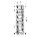
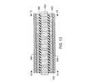
図2は、炭化水素を含有した累層を処理するためのインサイチュ変換システムの一部の一実施形態を略図で示したものである。加熱器100は、累層の少なくとも一部の中に配置されている。加熱器100は、累層の少なくとも一部に熱を提供して累層中の炭化水素を加熱している。供給ライン102を介して加熱器100にエネルギーを供給することができる。供給ライン102の構造は、累層の加熱に使用される1つ以上の加熱器のタイプに応じて異なる構造にすることができる。加熱器のための供給ライン102は、電気加熱器に電気を送ることができ、燃焼器に燃料を輸送することができ、または累層中を循環する熱交換流体を輸送することができる。 FIG. 2 schematically illustrates one embodiment of a portion of an in situ conversion system for processing a hydrocarbon-containing formation. The
生産井戸104を使用して累層から累層流体が移送される。生産井戸104から生産された累層流体は、収集配管106を通して処理設備108へ輸送することができる。また、累層流体は、加熱器100から生産することも可能である。たとえば加熱器100から流体を生産して、加熱器に隣接する累層の圧力を制御することができる。加熱器100から生産された流体は、配管を通して収集配管106へ輸送することができ、または生産された流体を配管を通して直接処理設備108へ輸送することができる。処理設備108は、分離ユニット、反応ユニット、品位向上ユニット、ガスから硫黄を除去するユニット、燃料電池、タービン、貯蔵容器を備えることができ、および/または生産された累層流体を処理するための他のシステムおよびユニットを備えることができる。 Formation well 104 is used to transfer formation fluid from the formation. The formation fluid produced from the production well 104 can be transported to the
炭化水素を処理するためのインサイチュ変換システムは、障壁井戸110を備えることができる。障壁井戸を使用して処理領域の周りに障壁が形成される。この障壁によって処理領域への流体の流入および/または処理領域からの流体の流出が抑制される。障壁井戸は、それらに限定されないが、脱水井戸、真空井戸、捕獲井戸、注入井戸、グラウト井戸、凍結井戸またはそれらの組合せを備えている。いくつかの実施形態においては、障壁井戸110は脱水井戸である。脱水井戸は、液体水を除去することができ、および/または加熱すべき累層の一部または加熱中の累層への液体水の流入を抑制することができる。図2に示す実施形態においては、脱水井戸は、加熱器100の一方の側に沿ってのみ展開しているが、通常、脱水井戸は、累層を加熱するために、使用されるすべての加熱器100または使用すべきすべての加熱器100を取り囲んでいる。 An in situ conversion system for treating hydrocarbons can include a
図2に示すように、累層中には、加熱器100だけではなく、1つ以上の生産井戸104が配置されている。累層流体は、生産井戸104を介して生産することができる。いくつかの実施形態においては、生産井戸104は加熱器を備えている。生産井戸内の加熱器は、生産井戸または生産井戸の近傍の累層の1つ以上の部分を加熱し、累層流体から気相を除去することができる。生産井戸からの液体を高温ポンピングする必要性を少なくすることができ、または除去することができる。液体の高温ポンピングを回避または制限することによって生産コストを著しく低減することができる。生産井戸を加熱することによって、または生産井戸を介して加熱することによって、(1)このような生産流体がオーババーデンに最も近い生産井戸の中を移動する際の生産流体の凝縮および/または還流を抑制することができ、(2)累層に入力される熱を大きくすることができ、および/または(3)生産井戸または生産井戸に最も近い累層の浸透性を大きくすることができる。いくつかのインサイチュ変換プロセスの実施形態においては、生産井戸から累層に供給される、生産井戸の1メートル当たりの熱の量は、累層を加熱する加熱器から累層に印加される、加熱器の1メートル当たりの熱の量より少ない。 As shown in FIG. 2, not only the
加熱器のいくつかの実施形態は、加熱器が特定の状態に到達すると、加熱器または加熱器の一部への電力をターンオフするスイッチ(たとえばヒューズおよび/またはサーモスタット)を備えている。特定の実施形態においては、温度制限加熱器を使用して、累層中の炭化水素を加熱するための熱が提供される。 Some embodiments of the heater include a switch (eg, a fuse and / or a thermostat) that turns off power to the heater or a portion of the heater when the heater reaches a particular state. In certain embodiments, a temperature limited heater is used to provide heat to heat the hydrocarbons in the formation.
温度制限加熱器は、インコンフィギュレーションであってもよく、および/または特定の温度で加熱器に自動温度制限特性を提供する物質を含有することができる。特定の実施形態においては、強磁性体が温度制限加熱器に使用されている。強磁性体は、強磁性体のキュリー温度またはキュリー温度に近い温度で温度を自己制限することができ、強磁性体に交流が印加されると、キュリー温度またはキュリー温度に近い温度になると提供する熱の量が減少する。特定の実施形態においては、強磁性体は、他の物質(たとえば高度に導電性の物質、優れた強度の物質、耐食性の物質またはそれらの組合せ)に結合されており、様々な電気特性および/または機械特性を提供している。温度制限加熱器のいくつかの部分には、この温度制限加熱器の他の部分より小さい抵抗を持たせることができる(異なる幾何構造にすることによって、および/または異なる強磁性体および/または非強磁性体を使用することによって)。温度制限加熱器の一部を様々な物質で構成し、および/またはそれらの寸法を様々な寸法にすることにより、所望の熱を加熱器の個々の部分から出力させることができる。強磁性体を温度制限加熱器に使用することは、通常、スイッチまたは他の制御デバイスを温度制限加熱器に使用する場合より安価であり、また、信頼性が高い。 The temperature limited heater may be in-configuration and / or may contain materials that provide automatic temperature limiting properties to the heater at a particular temperature. In certain embodiments, a ferromagnetic material is used in the temperature limited heater. The ferromagnet can self-limit the temperature at or near the Curie temperature of the ferromagnet, providing when alternating current is applied to the ferromagnet, the Curie temperature or near the Curie temperature is provided. The amount of heat is reduced. In certain embodiments, the ferromagnet is coupled to other materials (eg, highly conductive materials, high strength materials, corrosion resistant materials, or combinations thereof) and has various electrical properties and / or Or provide mechanical properties. Some parts of the temperature limited heater can have less resistance than other parts of this temperature limited heater (by different geometry and / or different ferromagnetic and / or non-magnetic) By using ferromagnetic material). By configuring a portion of the temperature limited heater with various materials and / or dimensionalizing them, the desired heat can be output from the individual portions of the heater. Using ferromagnetic materials for temperature limited heaters is usually cheaper and more reliable than using switches or other control devices for temperature limited heaters.
温度制限加熱器は、場合によっては他の加熱器より信頼性が高い。温度制限加熱器は、場合によっては累層中のホットスポットによる破壊または故障が少ない。いくつかの実施形態においては、温度制限加熱器は、累層を実質的に一様に加熱することができる。いくつかの実施形態においては、温度制限加熱器は、加熱器の長さ全体に沿ってより大きい平均熱出力で動作させることにより、より効果的に累層を加熱することができる。温度制限加熱器は、加熱器の任意のポイントに沿った温度が加熱器の最大動作温度を超えた場合、または最大動作温度を超えようとしている場合に、典型的な定ワット数加熱器の場合とは異なり、加熱器の電力を加熱器全体に対して小さくする必要がないため、加熱器の長さ全体に沿ってより大きい平均熱出力で動作する。温度制限加熱器の、この加熱器のキュリー温度に近づいている部分からの熱出力は、加熱器に印加される交流の制御された調整を必要とすることなく自動的に減少する。熱出力は、温度制限加熱器の一部の電気特性(たとえば電気抵抗)の変化によって自動的に減少する。したがって加熱プロセスの大部分にわたって、より多くの出力が温度制限加熱器によって供給される。 Temperature limited heaters are sometimes more reliable than other heaters. Temperature limited heaters are less likely to break or fail due to hot spots in the formation. In some embodiments, the temperature limited heater can heat the formation substantially uniformly. In some embodiments, the temperature limited heater can heat the formation more effectively by operating at a higher average heat output along the entire length of the heater. Temperature limited heaters are typical constant wattage heaters when the temperature along any point of the heater exceeds or is about to exceed the maximum operating temperature of the heater Unlike, the heater power does not need to be small relative to the entire heater, so it operates at a higher average heat output along the entire length of the heater. The heat output from the portion of the temperature limited heater that is approaching the Curie temperature of the heater is automatically reduced without requiring a controlled adjustment of the alternating current applied to the heater. The heat output is automatically reduced by changes in some electrical properties (eg, electrical resistance) of the temperature limited heater. Thus, more power is provided by the temperature limited heater throughout the majority of the heating process.
一実施形態においては、温度制限加熱器を備えたシステムは、交流または変調直流によって温度制限加熱器にエネルギーが供給されると、最初に第1の熱出力を提供し、次いで、温度制限加熱器の電気抵抗部分の温度がキュリー温度に近づき、またはキュリー温度に到達し、あるいはキュリー温度を超えると、提供する熱の量が減少する。温度制限加熱器は、坑口に供給される交流または変調直流によってエネルギーを供給することができる。坑口は、温度制限加熱器に電力を供給するために使用される電力源および他のコンポーネント(たとえば変調コンポーネント、変圧器および/またはコンデンサ)を備えることができる。温度制限加熱器は、累層の一部を加熱するために使用される多くの加熱器のうちの1つであってもよい。 In one embodiment, a system with a temperature limited heater first provides a first heat output when energy is supplied to the temperature limited heater by alternating current or modulated direct current, and then the temperature limited heater. The amount of heat provided decreases when the temperature of the electrical resistance portion of the electrode approaches, reaches or exceeds the Curie temperature. The temperature limited heater can be supplied with energy by alternating current or modulated direct current supplied to the wellhead. The wellhead can include a power source and other components (eg, modulation components, transformers and / or capacitors) used to power the temperature limited heater. The temperature limited heater may be one of many heaters used to heat a portion of the formation.
特定の実施形態においては、温度制限加熱器は、交流または変調直流が印加されると表皮効果加熱器または近接効果加熱器として動作する導体を備えている。表皮効果によって導体の内部への電流浸入の深さが制限される。強磁性体の場合、表皮効果は導体の透磁率によって支配される。強磁性体の比透磁率は、通常、10と1000の間である(たとえば強磁性体の比透磁率は、通常、少なくとも10であり、場合によっては少なくとも50、100、500、1000またはそれ以上である)。強磁性体の温度がキュリー温度を超えて上昇すると、および/または印加される電流が大きくなると、強磁性体の透磁率が実質的に減少し、表皮作用の深さが急激に深くなる(たとえば表皮作用の深さは透磁率の平方根の逆数で深くなる)。透磁率が減少することにより、キュリー温度に近づき、またはキュリー温度に到達し、あるいはキュリー温度を超えると、および/または印加される電流が大きくなると、導体のAC抵抗または変調DC抵抗が小さくなる。温度制限加熱器が実質的に一定の電流源によって電力が供給されると、温度制限加熱器の、キュリー温度に近くなった部分、またはキュリー温度に到達した部分、あるいはキュリー温度を超えた部分は熱の散逸が減少する。温度制限加熱器のキュリー温度またはキュリー温度に近い温度ではないセクションは、表皮効果加熱による支配が可能であり、したがって温度制限加熱器は、より大きい抵抗負荷によってより多くの熱を散逸させることができる。 In certain embodiments, the temperature limited heater comprises a conductor that operates as a skin effect heater or proximity effect heater when an alternating or modulated direct current is applied. The skin effect limits the depth of current penetration into the conductor. For ferromagnetic materials, the skin effect is governed by the magnetic permeability of the conductor. The relative permeability of ferromagnets is typically between 10 and 1000 (eg, the relative permeability of ferromagnets is usually at least 10 and in some cases at least 50, 100, 500, 1000 or more Is). As the temperature of the ferromagnet rises above the Curie temperature and / or as the applied current increases, the permeability of the ferromagnet substantially decreases and the depth of skin action increases sharply (eg, The depth of the skin action increases with the reciprocal of the square root of the permeability). Decreasing the permeability reduces the AC resistance or modulated DC resistance of the conductor as it approaches, reaches or exceeds the Curie temperature, and / or as the applied current increases. When a temperature limited heater is powered by a substantially constant current source, the portion of the temperature limited heater that is close to, or has reached or exceeded the Curie temperature Heat dissipation is reduced. Sections that are not at or near the Curie temperature of temperature limited heaters can be dominated by skin effect heating, so temperature limited heaters can dissipate more heat with larger resistive loads .
キュリー温度加熱器は、はんだ付け設備、医療アプリケーションのための加熱器およびオーブンの加熱素子に使用されている。Lamomeらに対する米国特許第5,579,575号、Henschenらに対する米国特許第5,065,501号、およびYagnikらに対する米国特許第5,512,732号に、これらの用途のいくつかが開示されている。Whitneyらに対する米国特許第4,849,611号に、反応コンポーネント、抵抗加熱コンポーネントおよび温度応答コンポーネントを備えた、間隔を隔てた複数の離散加熱ユニットが記述されている。 Curie temperature heaters are used in soldering equipment, heaters for medical applications and oven heating elements. Some of these applications are disclosed in US Pat. No. 5,579,575 to Lamome et al., US Pat. No. 5,065,501 to Henschen et al. And US Pat. No. 5,512,732 to Yanik et al. ing. U.S. Pat. No. 4,849,611 to Whitney et al. Describes a plurality of spaced apart discrete heating units comprising a reaction component, a resistance heating component and a temperature response component.
温度制限加熱器を使用して累層中の炭化水素を加熱する利点は、所望する温度動作範囲にキュリー温度を有するように導体が選択されることである。所望の動作温度範囲内で動作させることにより、温度制限加熱器および他の設備の温度を設計限界温度未満に維持しつつ、累層中に実質的に熱を注入することができる。設計限界温度は、腐蝕、クリープおよび/または変形などの特性が悪影響を受ける温度である。温度制限加熱器の温度制限特性によって、累層中の低熱伝導率「ホットスポット」に隣接する温度制限加熱器の過熱および断線が抑制される。いくつかの実施形態においては、温度制限加熱器は、熱出力を小さくするかまたは制御することができ、および/または温度制限加熱器に使用される物質に応じて、25℃、37℃、100℃、250℃、500℃、700℃、800℃、900℃を超える温度または最大1131℃までのより高い温度の熱に耐えることができる。 The advantage of using a temperature limited heater to heat the hydrocarbons in the formation is that the conductor is selected to have a Curie temperature in the desired temperature operating range. By operating within the desired operating temperature range, heat can be injected substantially into the formation while maintaining the temperature of the temperature limited heater and other equipment below the design limit temperature. The design limit temperature is the temperature at which properties such as corrosion, creep and / or deformation are adversely affected. The temperature limiting properties of the temperature limited heater suppress overheating and disconnection of the temperature limited heater adjacent to the low thermal conductivity “hot spot” in the formation. In some embodiments, the temperature limited heater can reduce or control the heat output and / or depending on the material used for the temperature limited heater, 25 ° C., 37 ° C., 100 It can withstand heat of temperatures above 250 ° C, 500 ° C, 700 ° C, 800 ° C, 900 ° C or higher temperatures up to 1131 ° C.
温度制限加熱器に入力されるエネルギーを制限して温度制限加熱器に隣接する低熱伝導率領域に適応する必要がないため、温度制限加熱器を使用することにより、定ワット数加熱器より多くの熱を累層中に注入することができる。たとえばGreen River油母ケツ岩の場合、最低品位油母ケツ岩層および最高品位油母ケツ岩層の熱伝導率に少なくとも3倍の差がある。このような累層を加熱する場合、温度制限加熱器を使用することにより、低熱伝導率層の温度によって制限される従来の加熱器を使用する場合より実質的に多くの熱が累層に伝達される。従来の加熱器の長さ全体に沿った熱出力は、加熱器が低熱伝導率層で過熱して断線しないよう、低熱伝導率層に適応させなければならない。温度制限加熱器の場合、高い温度の低熱伝導率層に隣接する熱出力を小さくすることができるが、温度制限加熱器の温度が低い残りの部分は、依然として大きい熱出力を提供することができる。炭化水素累層を加熱するための加熱器は、通常、加熱器の長さが長いため(たとえば少なくとも10m、100m、300m、少なくとも500m、1kmまたは最大10km)、キュリー温度またはキュリー温度に近い温度であるのは温度制限加熱器のごく一部にすぎず、温度制限加熱器の長さの大部分はキュリー温度未満で動作させることができる。 By using a temperature limited heater, more energy than a constant wattage heater can be obtained because it is not necessary to limit the energy input to the temperature limited heater to accommodate the low thermal conductivity region adjacent to the temperature limited heater. Heat can be injected into the formation. For example, in the case of the Green River oil basalt, there is a difference of at least 3 times in the thermal conductivity of the lowest grade oil basalt layer and the highest grade oil basalt layer. When heating such formations, a temperature limited heater is used to transfer substantially more heat to the formation than using a conventional heater limited by the temperature of the low thermal conductivity layer. Is done. The heat output along the entire length of the conventional heater must be adapted to the low thermal conductivity layer so that the heater does not overheat and break in the low thermal conductivity layer. In the case of a temperature limited heater, the heat output adjacent to the high temperature low thermal conductivity layer can be reduced, while the remaining temperature of the temperature limited heater can still provide a large heat output. . Heaters for heating hydrocarbon formations are typically at or near the Curie temperature because of the long heater length (eg, at least 10 m, 100 m, 300 m, at least 500 m, 1 km or up to 10 km). There are only a small portion of temperature limited heaters, and the majority of temperature limited heater lengths can be operated below the Curie temperature.
温度制限加熱器を使用することによって熱を効果的に累層に伝達することができる。熱が効果的に伝達されるため、累層を所望の温度に加熱するために必要な時間が短縮される。たとえばGreen River油母ケツ岩の場合、従来の定ワット数加熱器を使用した12m加熱器井戸間隔による熱分解には、通常、9.5年ないし10年の加熱が必要である。同じ加熱器間隔の場合、温度制限加熱器を使用することにより、加熱器設備の温度を設備設計限界温度未満の温度に維持しつつ、より大きい平均熱出力を出力することができる。温度制限加熱器によって提供される平均熱出力がより大きいため、定ワット数加熱器によって提供されるより小さい平均熱出力の場合と比較すると、より短期間で累層に熱分解が生じる。たとえばGreen River油母ケツ岩の場合、12m加熱器井戸間隔で温度制限加熱器を使用した場合、5年で熱分解が生じる。温度制限加熱器は、加熱器井戸が互いに接近しすぎている不正確な井戸間隔すなわちせん孔によるホットスポットの効力を打ち消す。特定の実施形態においては、温度制限加熱器を使用することにより、間隔が空きすぎている加熱器井戸に出力される電力を常に大きくすることができ、または互いに接近しすぎている加熱器井戸に出力される電力を制限することができる。また、温度制限加熱器は、オーババーデンおよびアンダバーデンに隣接する領域により多くの電力を供給し、この領域における温度損失を補償することも可能である。 Heat can be effectively transferred to the formation by using a temperature limited heater. Because heat is effectively transferred, the time required to heat the formation to the desired temperature is reduced. For example, in the case of Green River oil mounds, pyrolysis with a 12 m heater well spacing using a conventional constant wattage heater typically requires heating from 9.5 to 10 years. For the same heater spacing, a temperature limited heater can be used to output a higher average heat output while maintaining the heater equipment temperature below the equipment design limit temperature. Due to the higher average heat output provided by the temperature limited heater, pyrolysis occurs in the formation in a shorter period of time compared to the lower average heat output provided by the constant wattage heater. For example, in the case of the Green River gangue, pyrolysis occurs in 5 years if a temperature limited heater is used with a 12 m heater well spacing. Temperature limited heaters counteract the effects of inaccurate well spacing or hot spots due to perforations where the heater wells are too close together. In certain embodiments, by using temperature limited heaters, the power output to heater wells that are too far apart can always be increased, or to heater wells that are too close to each other. The output power can be limited. The temperature limited heater can also supply more power to the area adjacent to the overburden and underbarden to compensate for temperature loss in this area.
温度制限加熱器は、多くのタイプの累層に有利に使用することができる。たとえば、タールサンド累層または重炭化水素を含有した比較的浸透性の累層に温度制限加熱器を使用して、流体、流動化流体の粘性を小さくし、および/またはドリルホールまたはドリルホールの近傍あるいは累層中の流体の放射状流を強化するための制御可能な低温度出力を提供することができる。温度制限加熱器を使用して、累層の近ドリルホール領域の過熱による過剰コークスの形成を抑制することができる。 Temperature limited heaters can be advantageously used for many types of formations. For example, temperature limited heaters are used on tar sand formations or relatively permeable formations containing heavy hydrocarbons to reduce the viscosity of fluids, fluidizing fluids, and / or drill holes or drill hole A controllable low temperature output can be provided to enhance the radial flow of fluid in the vicinity or in the formation. A temperature limited heater can be used to suppress the formation of excess coke due to overheating of the near drill hole region of the formation.
いくつかの実施形態においては、温度制限加熱器を使用することにより、高価な温度制御回路を使用する必要性が除去されるか、または減少する。たとえば、温度制限加熱器を使用することにより、温度検層を実行する必要性および/またはホットスポットにおける潜在過熱を監視するための固定熱電対を加熱器上に使用する必要性が除去されるか、または減少する。 In some embodiments, the use of temperature limited heaters eliminates or reduces the need to use expensive temperature control circuitry. For example, can a temperature limited heater be used to eliminate the need to perform temperature logging and / or to use a fixed thermocouple on the heater to monitor potential overheating at the hot spot Or decrease.
いくつかの実施形態においては、温度制限加熱器は、標準の加熱器より製造が経済的である。典型的な強磁性体には、鉄、炭素鋼またはフェライトステンレス鋼が含まれている。このような物質は、絶縁導体(鉱物絶縁ケーブル)加熱器に典型的に使用される、ニーケルをベースとする加熱合金(ニクロム、Kanthal(商標)(Bulten−Kanthal AB、Sweden)および/またはLOHM(商標)(Driver−Harris Company、Harrison、NJ)など)と比較すると安価である。温度制限加熱器の一実施形態においては、温度制限加熱器は、より低コストで、信頼性の高い加熱器にするために、絶縁導体加熱器として連続した長さで製造される。 In some embodiments, temperature limited heaters are more economical to manufacture than standard heaters. Typical ferromagnets include iron, carbon steel or ferritic stainless steel. Such materials are typically used in insulated conductor (mineral insulated cable) heaters, such as Nikel-based heating alloys (Nichrome, Kanthal ™ (Bulten-Kanthal AB, Sweden) and / or LOHM ( (Trademark) (Driver-Harris Company, Harrison, NJ, etc.). In one embodiment of the temperature limited heater, the temperature limited heater is manufactured in a continuous length as an insulated conductor heater in order to make it a lower cost and more reliable heater.
温度制限加熱器のキュリー温度は、温度制限加熱器に使用される1つ以上の強磁性合金によって決まる。「American Institute of Physics Handbook」(第2版、McGraw−Hill、5−170〜5−176頁)に、様々な金属のキュリー温度データがリストされている。強磁性導体は、複数の強磁性元素(鉄、コバルトおよびニッケル)のうちの1つ以上および/またはこれらの元素の合金を含有することができる。いくつかの実施形態においては、強磁性導体には、タングステン(W)を含有した鉄−クロム(Fe−Cr)合金(たとえばHCM12AおよびSAVE12(Sumitomo Metals Co.、Japan))および/またはクロムを含有した鉄の合金(たとえばFe−Cr合金、Fe−Cr−W合金、Fe−Cr−V(バナジウム)合金、Fe−Cr−Nn(ニオブ)合金)が含まれている。3つの主要強磁性元素のうち、鉄のキュリー温度は約770℃であり、コバルト(Co)のキュリー温度は約1131℃であり、ニッケルのキュリー温度は約358℃である。鉄−コバルト合金は、鉄のキュリー温度より高いキュリー温度を有している。たとえば2重量%のコバルトを含有した鉄−コバルト合金のキュリー温度は約800℃であり、12重量%のコバルトを含有した鉄−コバルト合金のキュリー温度は約900℃であり、20重量%のコバルトを含有した鉄−コバルト合金のキュリー温度は約950℃である。鉄−ニッケル合金は、鉄のキュリー温度より低いキュリー温度を有している。たとえば20重量%のニッケルを含有した鉄−ニッケル合金のキュリー温度は約720℃であり、60重量%のニッケルを含有した鉄−ニッケル合金のキュリー温度は約560℃である。 The Curie temperature of the temperature limited heater is determined by one or more ferromagnetic alloys used in the temperature limited heater. Curie temperature data for various metals is listed in “American Institute of Physics Handbook” (2nd edition, McGraw-Hill, pp. 5-170-5-176). The ferromagnetic conductor can contain one or more of a plurality of ferromagnetic elements (iron, cobalt and nickel) and / or alloys of these elements. In some embodiments, the ferromagnetic conductor includes an iron-chromium (Fe—Cr) alloy containing tungsten (W) (eg, HCM12A and SAVE12 (Sumitomo Metals Co., Japan)) and / or chromium. And iron alloys (for example, Fe-Cr alloy, Fe-Cr-W alloy, Fe-Cr-V (vanadium) alloy, Fe-Cr-Nn (niobium) alloy) are included. Of the three main ferromagnetic elements, the Curie temperature of iron is about 770 ° C., the Curie temperature of cobalt (Co) is about 1131 ° C., and the Curie temperature of nickel is about 358 ° C. Iron-cobalt alloys have a Curie temperature higher than that of iron. For example, the Curie temperature of an iron-cobalt alloy containing 2 wt% cobalt is about 800 ° C., the Curie temperature of an iron-cobalt alloy containing 12 wt% cobalt is about 900 ° C., and 20 wt% cobalt. The Curie temperature of the iron-cobalt alloy containing is about 950 ° C. The iron-nickel alloy has a Curie temperature lower than that of iron. For example, the Curie temperature of an iron-nickel alloy containing 20 wt% nickel is about 720 ° C., and the Curie temperature of an iron-nickel alloy containing 60 wt% nickel is about 560 ° C.
合金として使用されるいくつかの非強磁性元素を使用すると、鉄のキュリー温度が高くなる。たとえば5.9重量%のバナジウムを含有した鉄−バナジウム合金のキュリー温度は約815℃である。他の非強磁性元素(たとえば炭素、アルミニウム、銅、ケイ素および/またはクロム)を鉄または他の強磁性体と合金にし、キュリー温度を低くすることができる。キュリー温度を高くする非強磁性体とキュリー温度を低くする非強磁性体とを組み合わせて鉄または他の強磁性体と合金にし、所望のキュリー温度および他の所望の物理的特性および/または化学的特性を備えた物質を提供することができる。いくつかの実施形態においては、キュリー温度物質は、NiFe2O4などのフェライトである。他の実施形態においては、キュリー温度物質は、FeNi3またはFe3Alなどの二成分化合物である。The use of some non-ferromagnetic elements used as alloys increases the Curie temperature of iron. For example, the Curie temperature of an iron-vanadium alloy containing 5.9% by weight vanadium is about 815 ° C. Other non-ferromagnetic elements (eg, carbon, aluminum, copper, silicon and / or chromium) can be alloyed with iron or other ferromagnetic materials to lower the Curie temperature. A non-ferromagnetic material that raises the Curie temperature and a non-ferromagnetic material that lowers the Curie temperature are combined into an alloy with iron or other ferromagnetic material to produce the desired Curie temperature and other desired physical properties and / or chemistry. A material with specific characteristics can be provided. In some embodiments, the Curie temperature material is a ferrite, such as NiFe2 O4 . In other embodiments, the Curie temperature material is a binary compound such as FeNi3 or Fe3 Al.
磁気特性は、通常、キュリー温度に近づくと崩壊する。「Handbook of Electrical Heating for Industry」(C.James Erickson著、IEEE Press、1995年)に、1%炭素鋼(1重量%の炭素を含有した鋼)の典型的な曲線が示されている。透磁率は、650℃を超える温度で損失を開始し、温度が730℃を超えると完全に損失するようになる。したがって自己制限温度は強磁性導体の実際のキュリー温度より若干低くなる。1%炭素鋼に流れる電流の表皮作用の深さは、室温で0.132cm(センチメートル)であり、720℃では0.445cmまで深くなる。720℃から730℃まで、表皮作用の深さは2.5cmを超える深さまで急激に深くなる。したがって1%炭素鋼を使用した温度制限加熱器の実施形態は、650℃と730℃の間で自己制限する。 Magnetic properties usually collapse as the Curie temperature is approached. A typical curve for 1% carbon steel (steel containing 1 wt% carbon) is shown in “Handbook of Electrical Heating for Industry” (C. James Erickson, IEEE Press, 1995). The magnetic permeability starts to be lost at a temperature exceeding 650 ° C. and becomes completely lost when the temperature exceeds 730 ° C. Therefore, the self-limiting temperature is slightly lower than the actual Curie temperature of the ferromagnetic conductor. The depth of the skin action of the current flowing through the 1% carbon steel is 0.132 cm (centimeter) at room temperature and increases to 0.445 cm at 720 ° C. From 720 ° C. to 730 ° C., the depth of skin action increases rapidly to a depth exceeding 2.5 cm. Thus, embodiments of temperature limited heaters using 1% carbon steel are self-limiting between 650 ° C and 730 ° C.
表皮作用の深さは、一般に、導電性物質中への交流または変調直流の有効浸入度で定義されている。通常、電流密度は、導体の外部表面から半径方向に沿った中心までの距離で指数的に減少する。電流密度が表面電流密度のほぼ1/eである深さは、表皮作用の深さと呼ばれている。直径が浸入度よりはるかに大きい円筒状固体ロッドの場合、または壁の厚さが浸入度より分厚い中空シリンダの場合、表皮作用の深さδは、
(1)δ=1981.5*(ρ/(μ*f))1/2
δ=インチ単位の表皮作用の深さ
ρ=動作温度における抵抗率(オーム−cm)
μ=比透磁率
f=周波数(Hz)
である。The depth of skin action is generally defined by the effective penetration of alternating current or modulated direct current into the conductive material. Usually, the current density decreases exponentially with the distance from the outer surface of the conductor to the center along the radial direction. The depth at which the current density is approximately 1 / e of the surface current density is called the skin effect depth. For cylindrical solid rods whose diameter is much larger than the penetration depth, or for hollow cylinders whose wall thickness is thicker than the penetration depth, the skin action depth δ is
(1) δ = 1981.5* (ρ / (μ* f))1/2
δ = depth of skin action in inches
ρ = resistivity at operating temperature (ohm-cm)
μ = relative permeability
f = frequency (Hz)
It is.
式1は、「Handbook of Electrical Heating for Industry」(C.James Erickson著、IEEE Press、1995年)から得られる。ほとんどの金属は、温度と共に抵抗率(ρ)が大きくなる。比透磁率は、通常、温度および電流によって変化する。補助的な式を使用して、温度および/または電流の両方に対する透磁率および/または表皮作用の深さの分散を評価することができる。電流に対するμの依存性は、磁界に対するμの依存性によるものである。
温度制限加熱器に使用される物質は、所望のターンダウン比率が提供されるように選択することができる。温度制限加熱器には、少なくとも1.1:1、2:1、3:1、4:1、5:1、10:1、30:1または50:1のターンダウン比率を選択することができる。もっと大きいターンダウン比率を使用することも可能である。選択されるターンダウン比率は、それらに限定されないが、温度制限加熱器が配置される累層のタイプおよび/またはドリルホールに使用される物質の温度限界を始めとする多くの要因によって決まる。いくつかの実施形態においては、補助的な銅または他の良好な電気導体を強磁性体に結合することによってターンダウン比率が大きくなる(たとえばキュリー温度を超える温度で抵抗をより小さくするために銅が追加される)。 The material used in the temperature limited heater can be selected to provide the desired turndown ratio. For temperature limited heaters, a turndown ratio of at least 1.1: 1, 2: 1, 3: 1, 4: 1, 5: 1, 10: 1, 30: 1 or 50: 1 can be selected. it can. It is also possible to use a larger turndown ratio. The turndown ratio selected will depend on many factors including, but not limited to, the type of formation in which the temperature limited heater is located and / or the temperature limit of the material used in the drill hole. In some embodiments, the turndown ratio is increased by coupling auxiliary copper or other good electrical conductors to the ferromagnet (eg, copper to reduce resistance at temperatures above the Curie temperature). Is added).
温度制限加熱器は、加熱器のキュリー温度未満の間、最小熱出力(電力出力)を提供することができる。特定の実施形態においては、最小熱出力は、少なくとも400W/m(1メートル当たりのワット)、600W/m、700W/m、800W/mまたはそれより大きい最大2000W/mである。温度制限加熱器は、温度制限加熱器のセクションの温度がキュリー温度に近づくかまたはキュリー温度を超えると、温度制限加熱器のセクション毎に熱出力の量が減少する。減少する熱の量は、キュリー温度未満の温度における熱出力より実質的に少なくすることができる。いくつかの実施形態においては、減少する熱の量は、最大400W/m、200W/m、100W/mであり、0W/mに近づけることも可能である。 Temperature limited heaters can provide a minimum heat output (power output) while below the Curie temperature of the heater. In certain embodiments, the minimum heat output is at least 400 W / m (watts per meter), 600 W / m, 700 W / m, 800 W / m or greater up to 2000 W / m. The temperature limited heater reduces the amount of heat output per section of the temperature limited heater as the temperature of the temperature limited heater section approaches or exceeds the Curie temperature. The amount of heat that is reduced can be substantially less than the heat output at temperatures below the Curie temperature. In some embodiments, the amount of heat that is reduced is up to 400 W / m, 200 W / m, 100 W / m, and can approach 0 W / m.
いくつかの実施形態においては、温度制限加熱器は、特定の動作温度範囲における温度制限加熱器の熱負荷に実質的に無関係に動作させることができる。「熱負荷」は、加熱システムから加熱システムの周囲へ熱が伝達される割合である。熱負荷は、周囲の温度および/または周囲の熱伝導率によって変化することを理解されたい。一実施形態においては、温度制限加熱器は、温度制限加熱器の一部に最も近い部分の熱負荷の1W/mの減少に対して、温度制限加熱器の動作温度が最大1.5℃、1℃または0.5℃だけ高くなるよう、温度制限加熱器のキュリー温度またはキュリー温度を超える温度で動作する。 In some embodiments, the temperature limited heater can be operated substantially independently of the thermal load of the temperature limited heater in a particular operating temperature range. “Heat load” is the rate at which heat is transferred from the heating system to the surroundings of the heating system. It should be understood that the thermal load varies with ambient temperature and / or ambient thermal conductivity. In one embodiment, the temperature limited heater has a temperature limited heater operating temperature of up to 1.5 ° C. for a 1 W / m reduction in heat load in a portion closest to a portion of the temperature limited heater, Operate at a temperature-limited heater Curie temperature or above the Curie temperature to be 1 ° C or 0.5 ° C higher.
AC抵抗または変調DC抵抗および/または温度制限加熱器の熱出力は、キュリー温度を超えるとキュリー効果によって急激に減少する。特定の実施形態においては、キュリー温度を超える温度またはキュリー温度に近い温度における電気抵抗または熱出力の値は、キュリー温度未満の特定のポイントにおける電気抵抗または熱出力の値の最大1/2である。いくつかの実施形態においては、キュリー温度を超える温度またはキュリー温度に近い温度における熱出力は、キュリー温度未満の特定のポイント(たとえばキュリー温度より30℃低い温度、キュリー温度より40℃低い温度、キュリー温度より50℃低い温度、またはキュリー温度より100℃低い温度)における熱出力の最大40%、30%、20%、10%または10%未満(1%まで)である。特定の実施形態においては、キュリー温度を超える温度またはキュリー温度に近い温度における電気抵抗は、キュリー温度未満の特定のポイント(たとえばキュリー温度より30℃低い温度、キュリー温度より40℃低い温度、キュリー温度より50℃低い温度、またはキュリー温度より100℃低い温度)における電気抵抗の80%、70%、60%、50%または50%未満(1%まで)に減少する。 The AC or modulated DC resistance and / or the heat output of the temperature limited heater rapidly decreases due to the Curie effect above the Curie temperature. In certain embodiments, the value of electrical resistance or heat output at a temperature above or near the Curie temperature is at most ½ of the value of electrical resistance or heat output at a particular point below the Curie temperature. . In some embodiments, the heat output at a temperature above or near the Curie temperature is a specific point below the Curie temperature (eg, a temperature 30 ° C. lower than the Curie temperature, a temperature 40 ° C. lower than the Curie temperature, Up to 40%, 30%, 20%, 10% or less than 10% (up to 1%) of the heat output at a temperature 50 ° C below the temperature, or 100 ° C below the Curie temperature). In certain embodiments, the electrical resistance at a temperature above or near the Curie temperature is a specific point below the Curie temperature (eg, a temperature 30 ° C. below the Curie temperature, a temperature 40 ° C. below the Curie temperature, a Curie temperature). It is reduced to 80%, 70%, 60%, 50% or less than 50% (up to 1%) of the electrical resistance at temperatures lower than 50 ° C or 100 ° C lower than the Curie temperature).
いくつかの実施形態においては、強磁性体の表皮作用の深さを変えるためにAC周波数が調整される。たとえば室温における1%炭素鋼の表皮作用の深さは、60Hzで0.132cm、180Hzで0.0762cmおよび440Hzで0.046cmである。加熱器の直径は、通常、表皮作用の深さの2倍より大きいため、より高い周波数を使用することによって(また、延いては直径がより小さい加熱器を使用することによって)加熱器のコストが減少する。固定幾何構造の場合、周波数が高くなるほどターンダウン比率が大きくなる。より高い周波数におけるターンダウン比率は、より低い周波数におけるターンダウン比率に、より高い周波数をより低い周波数で割り、その平方根を掛けることによって計算される。いくつかの実施形態においては、100Hzと1000Hzの間、140Hzと200Hzの間または400Hzと600Hzの間の周波数が使用されている(たとえば180Hz、540Hzまたは720Hz)。いくつかの実施形態においては、高い周波数を使用することができる。1000Hzを超える周波数であってもよい。 In some embodiments, the AC frequency is adjusted to change the depth of the skin action of the ferromagnetic material. For example, the depth of skin action of 1% carbon steel at room temperature is 0.132 cm at 60 Hz, 0.0762 cm at 180 Hz, and 0.046 cm at 440 Hz. The diameter of the heater is usually greater than twice the depth of skin action, so by using a higher frequency (and thus by using a heater with a smaller diameter) the cost of the heater Decrease. For a fixed geometry, the turndown ratio increases with increasing frequency. The turndown ratio at the higher frequency is calculated by dividing the turndown ratio at the lower frequency by the higher frequency divided by the lower frequency and multiplying by its square root. In some embodiments, frequencies between 100 and 1000 Hz, between 140 and 200 Hz, or between 400 and 600 Hz are used (eg, 180 Hz, 540 Hz, or 720 Hz). In some embodiments, higher frequencies can be used. The frequency may exceed 1000 Hz.
温度制限加熱器は、温度制限加熱器のキュリー温度に到達するまで実質的に一定の表皮作用の深さを得るために、温度制限加熱器が冷たい間はより低い周波数で動作させ、また、温度制限加熱器が熱くなるとより高い周波数で動作させることができる。しかしながら、電源、変圧器または周波数を交番させる電流変調器などの高価なコンポーネントの必要性がより少ないため、一般的には線路周波数加熱であることが好ましい。線路周波数は、電流の一般供給周波数である。線路周波数は、通常は60Hzであるが、電流の供給源に応じて50Hzまたは他の周波数であってもよい。固体可変周波数電源などの商用的に入手可能な設備を使用して、より高い周波数を生産することができる。三相電力を周波数が3倍の単相電力に変換する変圧器は、商用的に入手することができる。たとえば60Hzの高電圧三相電力をより低い電圧の180Hz単相電力に変換することができる。このような変圧器は、固体可変周波数電源より安価であり、より効率的にエネルギーを使用することができる。特定の実施形態においては、温度制限加熱器に供給される電力の周波数を高くするために、三相電力を単相電力に変換する変圧器が使用されている。 The temperature limited heater operates at a lower frequency while the temperature limited heater is cold to obtain a substantially constant skin action depth until the Curie temperature of the temperature limited heater is reached, and the temperature When the limiting heater becomes hot, it can be operated at a higher frequency. However, line frequency heating is generally preferred because there is less need for expensive components such as power supplies, transformers, or current modulators that alternate frequency. The line frequency is the general supply frequency of the current. The line frequency is typically 60 Hz, but may be 50 Hz or other frequencies depending on the current source. Higher frequencies can be produced using commercially available equipment such as solid state variable frequency power supplies. Transformers that convert three-phase power into single-phase power that is three times the frequency are commercially available. For example, 60 Hz high voltage three phase power can be converted to a
特定の実施形態においては、変調DC(たとえばチョップDC、波形変調DCまたはサイクルDC)を使用して温度制限加熱器に電力を提供することができる。DC変調器またはDCチョッパをDC電源に結合して変調直流出力を提供することができる。いくつかの実施形態においては、DC電源は、DCを変調するための手段を備えることができる。DC変調器の実施例の1つは、DC−DC変換器システムである。DC−DC変換器システムは、当分野で広く知られている。通常、DCが変調されるか、または所望の波形にチョップされる。DC変調のための波形には、それらに限定されないが、方形波、正弦波、変形正弦波、変形方形波、長方形波形および他の規則的な波形または不規則な波形が含まれている。 In certain embodiments, a modulated DC (eg, chopped DC, waveform modulated DC or cycle DC) can be used to provide power to the temperature limited heater. A DC modulator or DC chopper can be coupled to the DC power source to provide a modulated DC output. In some embodiments, the DC power source can comprise means for modulating the DC. One example of a DC modulator is a DC-DC converter system. DC-DC converter systems are widely known in the art. Usually, the DC is modulated or chopped to the desired waveform. Waveforms for DC modulation include, but are not limited to, square waves, sine waves, modified sine waves, deformed square waves, rectangular waveforms, and other regular or irregular waveforms.
変調DCの周波数は、通常、変調DC波形によって画定される。したがって変調DC波形を選択することによって所望の変調DC周波数を提供することができる。形状および/または変調DC波形の変調の速度(チョッピングの速度など)は、変調DC周波数を変えることによって変更することができる。DCは、一般に利用可能なAC周波数より高い周波数で変調することができる。たとえば変調DCは、少なくとも1000Hzの周波数で提供することができる。有利には、供給される電流の周波数をより大きい値にすると、温度制限加熱器のターンダウン比率が大きくなる。 The frequency of the modulated DC is usually defined by the modulated DC waveform. Accordingly, a desired modulated DC frequency can be provided by selecting a modulated DC waveform. The shape and / or the rate of modulation of the modulated DC waveform (such as the speed of chopping) can be changed by changing the modulation DC frequency. The DC can be modulated at a frequency higher than the generally available AC frequency. For example, the modulated DC can be provided at a frequency of at least 1000 Hz. Advantageously, the higher the frequency of the supplied current, the greater the turndown ratio of the temperature limited heater.
特定の実施形態においては、変調DC波形を調整または変更して、変調DC周波数が変更される。DC変調器は、温度制限加熱器を使用している間、任意の時間に、高電流または高電圧で変調DC波形を調整または変更することができる。したがって、温度制限加熱器に提供される変調DCは、単一周波数さらには限られた周波数値のセットに限定されない。通常、DC変調器を使用して波形を選択する場合、変調DC周波数の範囲を広くすることができ、また、変調DC周波数の離散制御が可能になる。したがって変調DC周波数は、全く固有の値でより容易に設定することができ、それに対してAC周波数は、通常、線路周波数の増分値に限定されている。変調DC周波数を離散制御することにより、温度制限加熱器のターンダウン比率をより選択的に制御することができる。温度制限加熱器のターンダウン比率を選択的に制御することができるため、より広範囲の物質を使用して温度制限加熱器を設計し、構築することができる。 In certain embodiments, the modulated DC waveform is adjusted or changed to change the modulated DC frequency. The DC modulator can adjust or change the modulated DC waveform at high current or high voltage at any time while using the temperature limited heater. Thus, the modulated DC provided to the temperature limited heater is not limited to a single frequency or even a limited set of frequency values. Usually, when a waveform is selected using a DC modulator, the range of the modulation DC frequency can be widened, and discrete control of the modulation DC frequency becomes possible. Thus, the modulation DC frequency can be set more easily with a totally unique value, whereas the AC frequency is usually limited to increments of the line frequency. By discretely controlling the modulation DC frequency, the turndown ratio of the temperature limited heater can be controlled more selectively. Because the turndown ratio of the temperature limited heater can be selectively controlled, a wider range of materials can be used to design and build the temperature limited heater.
いくつかの実施形態においては、使用中、変調DC周波数またはAC周波数を調整して、温度制限加熱器の特性(たとえば温度または圧力などの地中の状態)の変化が補償される。温度制限加熱器に提供される変調DC周波数またはAC周波数は、評価済みのダウンホールの状態に基づいて変更される。たとえばドリルホール内の温度制限加熱器の温度が上昇すると、場合によっては温度制限加熱器に提供される電流の周波数を高くし、延いては温度制限加熱器のターンダウン比率を大きくすることが有利である。一実施形態においては、ドリルホール内の温度制限加熱器のダウンホール温度が評価される。 In some embodiments, in use, the modulated DC or AC frequency is adjusted to compensate for changes in the characteristics of the temperature limited heater (eg, ground conditions such as temperature or pressure). The modulated DC frequency or AC frequency provided to the temperature limited heater is changed based on the evaluated downhole condition. For example, if the temperature of the temperature limited heater in the drill hole increases, it may be advantageous to increase the frequency of the current provided to the temperature limited heater, and in turn increase the turndown ratio of the temperature limited heater. It is. In one embodiment, the downhole temperature of the temperature limited heater in the drill hole is evaluated.
特定の実施形態においては、変調DC周波数またはAC周波数を変更して温度制限加熱器のターンダウン比率が調整される。ターンダウン比率を調整して、温度制限加熱器の長さに沿って生じるホットスポットを補償することができる。ターンダウン比率は、たとえば温度制限加熱器が特定の位置で熱くなりすぎることによって大きくなる。いくつかの実施形態においては、変調DC周波数またはAC周波数を変更して、地中の状態を評価することなくターンダウン比率が調整される。 In certain embodiments, the modulation DC frequency or AC frequency is changed to adjust the turndown ratio of the temperature limited heater. The turndown ratio can be adjusted to compensate for hot spots that occur along the length of the temperature limited heater. The turndown ratio is increased by, for example, the temperature limited heater becoming too hot at a particular location. In some embodiments, the modulation DC frequency or AC frequency is changed to adjust the turndown ratio without evaluating the underground conditions.
温度制限加熱器は、誘導負荷を生産することができる。この誘導負荷は、抵抗性熱出力の生産だけでなく、磁界を生産するために強磁性体によって使用される印加電流の一部によるものである。温度制限加熱器のダウンホール温度が変化すると、温度制限加熱器の強磁性体の磁気特性が温度によって変化するため、温度制限加熱器の誘導負荷が変化する。温度制限加熱器の誘導負荷は、温度制限加熱器に印加される電流と電圧の間の位相のずれの原因になることがある。 Temperature limited heaters can produce inductive loads. This inductive load is due not only to the production of resistive heat output, but also to part of the applied current used by the ferromagnet to produce a magnetic field. When the downhole temperature of the temperature limited heater changes, the magnetic property of the ferromagnetic material of the temperature limited heater changes with temperature, so the induction load of the temperature limited heater changes. The inductive load of the temperature limited heater can cause a phase shift between the current and voltage applied to the temperature limited heater.
温度制限加熱器に印加される実際の電力の減少は、電流波形の時間のずれ(たとえば電流は、誘導負荷のために電圧に対して位相がずれている)によって、および/または電流波形のひずみ(たとえば非線形負荷によって導入される高調波による電流波形のひずみ)によって生じることがある。したがって位相のずれまたは波形のひずみのため、選択された量の電力を印加するためには、場合によってはもっと多くの電流が必要である。印加される実際の電力と、同じ電流が同相であり、また、ひずんでいない場合に伝送されることになる皮相電力との比率が力率である。力率は常に1以下である。波形に位相のずれまたはひずみが存在しない場合、力率は1である。 The actual reduction in power applied to the temperature limited heater can be due to time lags in the current waveform (eg, current is out of phase with respect to voltage due to inductive loads) and / or current waveform distortion. (For example, current waveform distortion due to harmonics introduced by a non-linear load). Therefore, more current is sometimes required to apply a selected amount of power due to phase shift or waveform distortion. The power factor is the ratio between the actual power applied and the apparent current that will be transmitted when the same current is in phase and not distorted. The power factor is always 1 or less. The power factor is 1 when there is no phase shift or distortion in the waveform.
位相のずれのために実際に加熱器に印加される電力は、式2で表される。 The electric power actually applied to the heater due to the phase shift is expressed by
(2) P=I×V×cos(θ)
Pは温度制限加熱器に印加される実際の電力、Iは印加される電流、Vは印加される電圧、θは電圧と電流の間の位相角の差である。波形にひずみが存在しない場合、cos(θ)は力率に等しい。より高い周波数(たとえば少なくとも1000Hz、1500Hzまたは2000Hzの変調DC周波数)では、位相のずれおよび/またはひずみに関わる問題は、より顕著である。(2) P = I × V × cos (θ)
P is the actual power applied to the temperature limited heater, I is the applied current, V is the applied voltage, and θ is the phase angle difference between the voltage and current. If there is no distortion in the waveform, cos (θ) is equal to the power factor. At higher frequencies (eg, a modulated DC frequency of at least 1000 Hz, 1500 Hz, or 2000 Hz), problems associated with phase shifts and / or distortion are more pronounced.
いくつかの実施形態においては、電圧および/または電流を調整して強磁性体の表皮作用の深さが変更される。電圧を高くし、および/または電流を小さくすることにより、強磁性体の表皮作用の深さを浅くすることができる。表皮作用の深さをより浅くすることによって温度制限加熱器の直径をより小さくすることができ、したがって設備のコストを低減することができる。特定の実施形態においては、印加される電流は、少なくとも1アンペア、10アンペア、70アンペア、100アンペア、200アンペア、500アンペアまたはそれ以上の最大2000アンペアである。いくつかの実施形態においては、200ボルトを超える電圧、480ボルトを超える電圧、650ボルトを超える電圧、1000ボルトを超える電圧、1500ボルトを超える電圧またはそれ以上の最大10000ボルトの電圧の交流が供給される。 In some embodiments, the depth of the skin action of the ferromagnet is altered by adjusting the voltage and / or current. By increasing the voltage and / or reducing the current, the skin action depth of the ferromagnetic material can be reduced. By making the depth of skin action shallower, the diameter of the temperature limited heater can be made smaller, thus reducing the cost of the equipment. In certain embodiments, the applied current is at least 1 amp, 10 amps, 70 amps, 100 amps, 200 amps, 500 amps or more up to 2000 amps. In some embodiments, an alternating current of more than 200 volts, a voltage greater than 480 volts, a voltage greater than 650 volts, a voltage greater than 1000 volts, a voltage greater than 1500 volts, or higher, up to 10,000 volts is provided. Is done.
一実施形態においては、温度制限加熱器は、外部導体の内側に内部導体を備えている。内部導体および外部導体は、中心軸の周りに放射状に配置されている。内部導体および外部導体は、絶縁層によって分離することができる。特定の実施形態においては、内部導体および外部導体は、温度制限加熱器の底で結合されている。内部導体を介して温度制限加熱器に電流を流し、外部導体を介して電流を戻すことができる。これらの導体のいずれか一方または両方が強磁性体を含有することができる。 In one embodiment, the temperature limited heater includes an inner conductor inside the outer conductor. The inner conductor and the outer conductor are arranged radially around the central axis. The inner conductor and the outer conductor can be separated by an insulating layer. In certain embodiments, the inner and outer conductors are joined at the bottom of the temperature limited heater. Current can be passed through the temperature limited heater via the inner conductor and current can be returned via the outer conductor. Either one or both of these conductors can contain a ferromagnetic material.
絶縁層は、酸化マグネシウム、酸化アルミニウム、二酸化ケイ素、酸化ベリリウム、窒化ホウ素、窒化ケイ素またはそれらの組合せなどの熱伝導率の大きい電気絶縁セラミックを備えることができる。絶縁層は、圧縮粉末(たとえば圧縮セラミック粉末)であってもよい。圧縮することによって熱伝導率を改善し、より良好な絶縁抵抗を提供することができる。より温度が低いアプリケーションの場合、たとえばフッ素樹脂、ポリイミド、ポリアミドおよび/またはポリエチレンでできた重合体絶縁材を使用することができる。いくつかの実施形態においては、重合体絶縁材は、過フルオロアルコキシ(PEA)またはポリエーテルエーテルケトン(PEEK(商標)(Victrex Ltd、England))でできている。絶縁層は、内部導体から外部導体への熱の伝達を促進するために実質的に赤外線を透過するように選択することができる。一実施形態においては、絶縁層は、透明な石英砂である。絶縁層は、空気またはヘリウム、窒素または六フッ化硫黄などの非反応性ガスであってもよい。絶縁層が空気または非反応性ガスである場合、内部導体と外部導体の間の電気接触を禁止するように設計された絶縁スペーサを設けることができる。絶縁スペーサは、たとえば高純度酸化アルミニウムまたは窒化ケイ素などの他の熱伝導性電気絶縁材を使用して構築することができる。絶縁スペーサは、Nextel(商標)312(3M Corporation、St.Paul、Minnesota)、マイカテープまたはガラス繊維などの繊維状セラミック材であってもよい。セラミック材は、アルミナ、ケイ酸アルミナ、ホウケイ酸アルミナ、窒化ケイ素、窒化ホウ素または他の物質でできている。 The insulating layer can comprise an electrically insulating ceramic with high thermal conductivity, such as magnesium oxide, aluminum oxide, silicon dioxide, beryllium oxide, boron nitride, silicon nitride, or combinations thereof. The insulating layer may be a compressed powder (for example, a compressed ceramic powder). Compression can improve thermal conductivity and provide better insulation resistance. For lower temperature applications, polymer insulation made of, for example, fluororesin, polyimide, polyamide and / or polyethylene can be used. In some embodiments, the polymeric insulation is made of perfluoroalkoxy (PEA) or polyetheretherketone (PEEK ™ (Victrex Ltd, England)). The insulating layer can be selected to transmit substantially infrared light to facilitate heat transfer from the inner conductor to the outer conductor. In one embodiment, the insulating layer is transparent quartz sand. The insulating layer may be air or a non-reactive gas such as helium, nitrogen or sulfur hexafluoride. If the insulating layer is air or a non-reactive gas, insulating spacers designed to prohibit electrical contact between the inner and outer conductors can be provided. Insulating spacers can be constructed using other thermally conductive electrical insulation materials such as, for example, high purity aluminum oxide or silicon nitride. The insulating spacer may be a fibrous ceramic material such as Nextel ™ 312 (3M Corporation, St. Paul, Minnesota), mica tape or glass fiber. The ceramic material is made of alumina, alumina silicate, alumina borosilicate, silicon nitride, boron nitride or other material.
特定の実施形態においては、外部導体は、耐食性および/または耐クリープ性のために選択される。一実施形態においては、304H、347H、347HH、316H、310H、347HP、NF709(Nippon Steel Corp.、Japan)ステンレス鋼またはそれらの組合せなどのオーステナイト(非強磁性)ステンレス鋼を外部導体に使用することができる。また、外部導体は、クラッド導体を備えることも可能である。たとえば、腐蝕を防止するために800Hまたは347Hステンレス鋼などの耐食性合金を強磁性炭素鋼チューブラの上に被覆することができる。高温強度を必要としない場合、いくつかのフェライトステンレス鋼のうちの1つなどの耐食性が良好な強磁性金属から外部導体を構築することができる。一実施形態においては、82.3重量%の鉄と17.7重量%のクロムのフェライト合金(キュリー温度678℃)によって所望の耐食性が提供される。 In certain embodiments, the outer conductor is selected for corrosion resistance and / or creep resistance. In one embodiment, austenitic (non-ferromagnetic) stainless steel such as 304H, 347H, 347HH, 316H, 310H, 347HP, NF709 (Nippon Steel Corp., Japan) stainless steel or combinations thereof is used for the outer conductor. Can do. The outer conductor can also include a clad conductor. For example, a corrosion resistant alloy such as 800H or 347H stainless steel can be coated over the ferromagnetic carbon steel tubular to prevent corrosion. If high temperature strength is not required, the outer conductor can be constructed from a ferromagnetic metal with good corrosion resistance, such as one of several ferritic stainless steels. In one embodiment, the desired corrosion resistance is provided by a ferrite alloy of 82.3% by weight iron and 17.7% by weight chromium (Curie temperature 678 ° C.).
「The Metals Handbook」(American Society of Materials(ASM))第8巻291頁に、鉄−クロム合金のキュリー温度対合金中のクロムの量のグラフが掲載されている。いくつかの温度制限加熱器の実施形態においては、個別の支持ロッドまたはチューブラ(347Hステンレス鋼でできている)が、鉄−クロム合金製の温度制限加熱器に結合されており、強度および/または耐クリープ性を提供している。支持材および/または強磁性体は、650℃で少なくとも20.7MPaの100,000時間クリープ破断強さが提供されるように選択することができる。いくつかの実施形態においては、100,000時間クリープ破断強さは、650℃で少なくとも13.8MPaであるか、または650℃で少なくとも6.9MPaである。たとえば347H鋼は、650℃または650℃を超える温度で有利なクリープ破断強さを有している。いくつかの実施形態においては、100,000時間クリープ破断強さは、6.9MPaから41.3MPaに及ぶ範囲にわたっており、より長い加熱器および/またはより大きい大地応力または流動応力に対してはそれ以上である。 “The Metals Handbook” (American Society of Materials (ASM)), Vol. 8, page 291, provides a graph of the Curie temperature of iron-chromium alloys versus the amount of chromium in the alloys. In some temperature limited heater embodiments, individual support rods or tubular (made of 347H stainless steel) are coupled to a temperature limited heater made of an iron-chromium alloy to provide strength and / or strength. Provides creep resistance. The support and / or ferromagnet can be selected to provide a 100,000 hour creep rupture strength of at least 20.7 MPa at 650 ° C. In some embodiments, the 100,000 hour creep rupture strength is at least 13.8 MPa at 650 ° C. or at least 6.9 MPa at 650 ° C. For example, 347H steel has advantageous creep rupture strength at temperatures of 650 ° C. or above 650 ° C. In some embodiments, the 100,000 hour creep rupture strength ranges from 6.9 MPa to 41.3 MPa, for longer heaters and / or larger ground or flow stresses. That's it.
内部強磁性導体および外部強磁性導体を備えた温度制限加熱器の実施形態においては、内部導体の外側および外部導体の内側に表皮効果電流経路が生じる。したがって、外部導体の内側の表皮効果電流経路に影響を及ぼすことなく、外部導体の外側をステンレス鋼などの耐食性合金で被覆することができる。 In an embodiment of a temperature limited heater with an inner ferromagnetic conductor and an outer ferromagnetic conductor, a skin effect current path is created outside the inner conductor and inside the outer conductor. Therefore, the outside of the outer conductor can be covered with a corrosion resistant alloy such as stainless steel without affecting the skin effect current path inside the outer conductor.
表皮作用の深さは、キュリー温度の近辺で急激に深くなるため、キュリー温度で少なくとも表皮作用の深さの厚さを有する強磁性導体を使用することにより、強磁性体のAC抵抗を著しく小さくすることができる。特定の実施形態においては、強磁性導体が銅などの高度に導電性の物質で被覆されていない場合、導体の厚さを、キュリー温度近辺における表皮作用の深さの1.5倍、キュリー温度近辺における表皮作用の深さの3倍、さらにはキュリー温度近辺における表皮作用の深さの10倍以上にすることができる。強磁性導体が銅で被覆されている場合、強磁性導体の厚さは、キュリー温度近辺における表皮作用の深さと実質的に同じにすることができる。いくつかの実施形態においては、銅で被覆された強磁性導体の厚さは、キュリー温度近辺における表皮作用の深さの少なくとも3/4である。 Since the depth of the skin action increases sharply in the vicinity of the Curie temperature, the AC resistance of the ferromagnetic material is significantly reduced by using a ferromagnetic conductor having a thickness of at least the skin action depth at the Curie temperature. can do. In certain embodiments, if the ferromagnetic conductor is not coated with a highly conductive material such as copper, the thickness of the conductor is 1.5 times the skin depth near the Curie temperature, the Curie temperature. The depth of the skin action in the vicinity can be 3 times the depth, and further, the depth of the skin action in the vicinity of the Curie temperature can be 10 times or more. If the ferromagnetic conductor is coated with copper, the thickness of the ferromagnetic conductor can be substantially the same as the skin depth near the Curie temperature. In some embodiments, the thickness of the copper-coated ferromagnetic conductor is at least 3/4 of the skin depth near the Curie temperature.
特定の実施形態においては、温度制限加熱器は、強磁性チューブラおよび非強磁性高導電率コアを備えた複合導体を備えている。非強磁性高導電率コアは、複合導体に必要な直径を小さくしている。たとえば複合導体は、厚さ0.298cmのフェライトステンレス鋼または炭素鋼がコアを取り囲んでいる直径0.575cmの銅クラッドのコアを備えた直径1.19cmの複合導体であってもよい。複合導体を使用することにより、キュリー温度近辺における温度制限加熱器の電気抵抗をより急激に減少させることができる。表皮作用の深さはキュリー温度の近辺で深くなるため、銅コアを備えることによって電気抵抗が極めて急激に減少する。 In certain embodiments, the temperature limited heater comprises a composite conductor with a ferromagnetic tubular and a non-ferromagnetic high conductivity core. The non-ferromagnetic high conductivity core has a reduced diameter required for the composite conductor. For example, the composite conductor may be a 1.19 cm diameter composite conductor with a 0.575 cm diameter copper clad core surrounded by a 0.298 cm thick ferritic stainless steel or carbon steel. By using the composite conductor, the electric resistance of the temperature limited heater near the Curie temperature can be reduced more rapidly. Since the depth of the skin action becomes deep in the vicinity of the Curie temperature, the electrical resistance decreases very rapidly by providing the copper core.
複合導体は、温度制限加熱器の導電率を大きくすることができ、および/またはより低い電圧での温度制限加熱器の動作を可能にしている。一実施形態においては、複合導体の抵抗対温度プロファイルは、複合導体の強磁性導体のキュリー温度に近い領域未満の温度で比較的平らである。いくつかの実施形態においては、温度制限加熱器の抵抗対温度プロファイルは、100℃と750℃の間または300℃と600℃の間で比較的平らである。また、たとえば温度制限加熱器の物質および/または物質の構成を調整することにより、他の温度範囲においても比較的平らな抵抗対温度プロファイルを得ることができる。特定の実施形態においては、複合導体の個々の物質の相対厚さは、所望の抵抗率対温度プロファイルが温度制限加熱器にもたらされるように選択される。 The composite conductor can increase the conductivity of the temperature limited heater and / or allows the temperature limited heater to operate at a lower voltage. In one embodiment, the composite conductor resistance vs. temperature profile is relatively flat at a temperature below a region close to the Curie temperature of the ferromagnetic conductor of the composite conductor. In some embodiments, the resistance versus temperature profile of the temperature limited heater is relatively flat between 100 ° C. and 750 ° C. or between 300 ° C. and 600 ° C. Also, a relatively flat resistance-to-temperature profile can be obtained at other temperature ranges, for example, by adjusting the material and / or material composition of the temperature limited heater. In certain embodiments, the relative thicknesses of the individual materials of the composite conductor are selected such that the desired resistivity versus temperature profile is provided to the temperature limited heater.
図3〜31は、温度制限加熱器の様々な実施形態を示したものである。これらの図のいくつかに示されている温度制限加熱器の実施形態の1つ以上の特徴は、これらの図に示されている温度制限加熱器の他の実施形態の1つ以上の特徴と組み合わせることができる。本明細書において説明されている特定の実施形態においては、温度制限加熱器は、60HzACの周波数で動作するように寸法化されている。温度制限加熱器の寸法は、温度制限加熱器を他のAC周波数で同様の方法で動作させるために、または変調DCを使用して同様の方法で動作させるために、本明細書において説明されている寸法から調整することができることを理解されたい。 Figures 3 to 31 show various embodiments of temperature limited heaters. One or more features of the temperature limited heater embodiments shown in some of these figures are one or more features of other embodiments of the temperature limited heater shown in these figures. Can be combined. In the particular embodiment described herein, the temperature limited heater is dimensioned to operate at a frequency of 60 Hz AC. The dimensions of the temperature limited heater are described herein in order to operate the temperature limited heater in a similar manner at other AC frequencies or in a similar manner using a modulated DC. It should be understood that adjustments can be made from the dimensions that are present.
図3は、強磁性セクションおよび非強磁性セクションを有する外部導体を備えた温度制限加熱器の一実施形態の断面図を示したものである。図4および5は、図3に示す実施形態の横断面図を示したものである。一実施形態においては、強磁性セクション140を使用して累層中の炭化水素層に熱が提供される。非強磁性セクション142は、累層のオーババーデンに使用される。非強磁性セクション142は、オーババーデンに熱をほとんど提供しないか、または全く提供しないため、この非強磁性セクション142によってオーババーデンの熱損失が抑制され、加熱器の効率が改善される。強磁性セクション140は、409ステンレス鋼または410ステンレス鋼などの強磁性体を備えている。強磁性セクション140の厚さは0.3cmである。非強磁性セクション142は、厚さ0.3cmの銅である。内部導体144は銅である。内部導体144の直径は0.9cmである。電気絶縁体146は、窒化ケイ素、窒化ホウ素、酸化マグネシウム粉末または他の適切な絶縁体物質である。電気絶縁体146の厚さは、0.1cmないし0.3cmである。 FIG. 3 shows a cross-sectional view of one embodiment of a temperature limited heater with an outer conductor having ferromagnetic and non-ferromagnetic sections. 4 and 5 show cross-sectional views of the embodiment shown in FIG. In one embodiment, the
図6は、シースの内部に配置された強磁性セクションおよび非強磁性セクションを有する外部導体を備えた温度制限加熱器の一実施形態の断面図を示したものである。図7、8および9は、図6に示す実施形態の横断面図を示したものである。強磁性セクション140は、厚さ0.6cmの410ステンレス鋼である。非強磁性セクション142は、厚さ0.6cmの銅である。内部導体144は、直径0.9cmの銅である。外部導体148には強磁性体が含まれている。外部導体148によって温度制限加熱器のオーババーデンセクションに若干の熱が提供される。オーババーデンに若干の熱を提供することにより、オーババーデン中における凝縮または流体の還流が抑制される。外部導体148は、外径3.0cm、厚さ0.6cmの409ステンレス鋼、410ステンレス鋼または446ステンレス鋼である。電気絶縁体146は、厚さ0.3cmの酸化マグネシウム粉末である。いくつかの実施形態においては、電気絶縁体146は、窒化ケイ素、窒化ホウ素または六角形型窒化ホウ素である。導電セクション150は、内部導体144を強磁性セクション140および/または外部導体148に結合することができる。 FIG. 6 illustrates a cross-sectional view of one embodiment of a temperature limited heater with an outer conductor having a ferromagnetic section and a non-ferromagnetic section disposed within the sheath. 7, 8 and 9 show cross-sectional views of the embodiment shown in FIG. The
図10は、強磁性外部導体を備えた温度制限加熱器の一実施形態の断面図を示したものである。温度制限加熱器は、耐食性ジャケット内に配置されている。導電層は、外部導体とジャケットの間に配置されている。図11および12は、図10に示す実施形態の横断面図を示したものである。外部導体148は、3/4インチスケジュール(Schedule)80 446ステンレス鋼管である。一実施形態においては、導電層152は、外部導体148とジャケット154の間に配置されている。導電層152は銅の層である。外部導体148は、導電層152で被覆されている。特定の実施形態においては、導電層152は、1つ以上のセグメントを備えている(たとえば導電層152は、1つ以上の銅管セグメントを備えている)。ジャケット154は、1−1/4インチスケジュール80 347Hステンレス鋼管または1−1/2インチスケジュール160 347Hステンレス鋼管である。一実施形態においては、内部導体144は、マイカテープの層およびガラス繊維絶縁材を使用してニッケル被覆銅線をより合せた4/0MGT−1000ファーネスケーブルである。4/0MGT−1000ファーネスケーブルは、ULタイプ5107である(Allied Wire and Cable(Phoenixville、Pennsylvania)から入手することができる)。導電セクション150は、内部導体144とジャケット154を結合している。一実施形態においては、導電セクション150は銅である。 FIG. 10 shows a cross-sectional view of one embodiment of a temperature limited heater with a ferromagnetic outer conductor. The temperature limited heater is placed in a corrosion resistant jacket. The conductive layer is disposed between the outer conductor and the jacket. 11 and 12 show cross-sectional views of the embodiment shown in FIG.
図13は、外部導体を備えた温度制限加熱器の一実施形態の断面図を示したものである。外部導体は、強磁性セクションおよび非強磁性セクションを備えている。温度制限加熱器は、耐食性ジャケット内に配置されている。導電層は、外部導体とジャケットの間に配置されている。図14および15は、図13に示す実施形態の横断面図を示したものである。強磁性セクション140は、厚さ0.9cmの409ステンレス鋼、410ステンレス鋼または446ステンレス鋼である。非強磁性セクション142は、厚さ0.9cmの銅である。強磁性セクション140および非強磁性セクション142はジャケット154内に配置されている。ジャケット154は、厚さ0.1cmの304ステンレス鋼である。導電層152は、銅の層である。電気絶縁体146は、厚さ0.1cmないし0.3cmの窒化ケイ素、窒化ホウ素または酸化マグネシウムである。内部導体144は、直径1.0cmの銅である。 FIG. 13 shows a cross-sectional view of one embodiment of a temperature limited heater with an outer conductor. The outer conductor includes a ferromagnetic section and a non-ferromagnetic section. The temperature limited heater is placed in a corrosion resistant jacket. The conductive layer is disposed between the outer conductor and the jacket. 14 and 15 show cross-sectional views of the embodiment shown in FIG. The
一実施形態においては、強磁性セクション140は、厚さ0.9cmの446ステンレス鋼である。ジャケット154は、厚さ0.6cmの410ステンレス鋼である。410ステンレス鋼は、446ステンレス鋼より高いキュリー温度を有している。このような温度制限加熱器は、温度制限加熱器から周囲の累層および/または周囲のあらゆる水(たとえばブライン、地下水または地層水)へ電流が容易に流れないように電流を「抑制する」ことができる。この実施形態においては、強磁性セクションがキュリー温度に到達するまでの間、電流の大半が強磁性セクション140を通って流れる。強磁性セクション140がキュリー温度に到達すると、電流の大半が導電層152を通って流れる。ジャケット154(410ステンレス鋼)の強磁性特性によってジャケットの外部へ流れる電流が抑制され、また、電流が「保持」される。また、温度制限加熱器に強度を提供する厚さをジャケット154に持たせることも可能である。 In one embodiment, the
図16Aおよび図16Bは、強磁性内部導体を備えた温度制限加熱器の一実施形態の断面図を示したものである。内部導体144は、1インチスケジュールXXS 446ステンレス鋼管である。いくつかの実施形態においては、内部導体144には、409ステンレス鋼、410ステンレス鋼、Invar36、合金42−6、合金52または他の強磁性体が含まれている。内部導体144の直径は2.5cmである。電気絶縁体146は、窒化ケイ素、窒化ホウ素、酸化マグネシウム、重合体、Nextelセラミック繊維、マイカまたはガラス繊維である。外部導体148は、銅または他の任意の非強磁性体、たとえばアルミニウムなどである。外部導体148はジャケット154に結合されている。ジャケット154は、304Hステンレス鋼、316Hステンレス鋼または347Hステンレス鋼である。この実施形態においては、熱の大半が内部導体144内で生産される。 16A and 16B show a cross-sectional view of one embodiment of a temperature limited heater with a ferromagnetic inner conductor.
図17Aおよび図17Bは、強磁性内部導体および非強磁性コアを備えた温度制限加熱器の一実施形態の断面図を示したものである。内部導体144には、446ステンレス鋼、409ステンレス鋼、410ステンレス鋼または他の強磁性体が含まれている。コア168は、内部導体144の内部に緊密に結合されている。コア168は、銅または他の非強磁性体のロッドである。コア168は、くみ出し操作に先立って、緊密嵌合内側内部導体144として挿入される。いくつかの実施形態においては、コア168および内部導体144は、共有押出し成形結合されている。外部導体148は347Hステンレス鋼である。電気絶縁体146を圧縮するための延伸操作または圧延操作によって、内部導体144とコア168の間の良好な電気接触を保証することができる。この実施形態においては、キュリー温度に近づくまで、主として内部導体144内で熱が生産される。次いで、交流がコア168に浸入すると抵抗が急激に小さくなる。 FIGS. 17A and 17B show cross-sectional views of one embodiment of a temperature limited heater with a ferromagnetic inner conductor and a non-ferromagnetic core.
図18Aおよび図18Bは、強磁性外部導体を備えた温度制限加熱器の一実施形態の断面図を示したものである。内部導体144は、ニッケルで被覆された銅である。電気絶縁体146は、窒化ケイ素、窒化ホウ素または酸化マグネシウムである。外部導体148は、1インチスケジュールXXS炭素鋼管である。この実施形態においては、主として外部導体148内で熱が生産されるため、電気絶縁体146の両端間の温度差が小さくなる。 18A and 18B show cross-sectional views of one embodiment of a temperature limited heater with a ferromagnetic outer conductor. The
図19Aおよび図19Bは、耐食性合金で被覆された強磁性外部導体を備えた温度制限加熱器の一実施形態の断面図を示したものである。内部導体144は銅である。外部導体148は、1インチスケジュールXXS446ステンレス鋼管である。外部導体148はジャケット154に結合されている。ジャケット154は、耐食性材料(たとえば347Hステンレス鋼)でできている。ジャケット154は、ドリルホール内の腐蝕性流体(たとえば硫化ガスおよび肌焼ガス)からの保護を提供している。主として外部導体148内で熱が生産されるため、電気絶縁体146の両端間の温度差が小さくなる。 FIGS. 19A and 19B show cross-sectional views of one embodiment of a temperature limited heater with a ferromagnetic outer conductor coated with a corrosion resistant alloy.
図20Aおよび図20Bは、強磁性外部導体を備えた温度制限加熱器の一実施形態の断面図を示したものである。外部導体は、導電層および耐食性合金で被覆されている。内部導体144は銅である。電気絶縁体146は、窒化ケイ素、窒化ホウ素または酸化マグネシウムである。外部導体148は、1インチスケジュール80 446ステンレス鋼管である。外部導体148はジャケット154に結合されている。ジャケット154は、耐食性材料でできている。一実施形態においては、導電層152は、外部導体148とジャケット154の間に配置されている。導電層152は銅の層である。主として外部導体148内で熱が生産されるため、電気絶縁体146の両端間の温度差が小さくなる。導電層152を使用することにより、外部導体がキュリー温度に近づくと、外部導体148の抵抗を急激に小さくすることができる。ジャケット154は、ドリルホール内の腐蝕性流体からの保護を提供している。 20A and 20B show cross-sectional views of one embodiment of a temperature limited heater with a ferromagnetic outer conductor. The outer conductor is covered with a conductive layer and a corrosion resistant alloy.
いくつかの実施形態においては、導体(たとえば内部導体、外部導体または強磁性導体)は、複数の異なる物質を含有した複合導体である。特定の実施形態においては、複合導体には複数の強磁性体が含まれている。いくつかの実施形態においては、複合強磁性導体には、放射状に配置された複数の物質が含まれている。特定の実施形態においては、複合導体は、強磁性導体および非強磁性導体を備えている。いくつかの実施形態においては、複合導体は、非強磁性コアの上に配置された強磁性導体を備えている。複数の物質を使用して、キュリー温度未満の温度領域で比較的平らな電気抵抗対温度プロファイルを得ることができ、および/またはキュリー温度またはキュリー温度に近い温度で電気抵抗率の急激な減少(大きなターンダウン比率の減少)を得ることができる。いくつかの事例においては、複数の物質を使用して、温度制限加熱器に複数のキュリー温度が提供される。 In some embodiments, the conductor (eg, inner conductor, outer conductor or ferromagnetic conductor) is a composite conductor containing a plurality of different materials. In certain embodiments, the composite conductor includes a plurality of ferromagnetic materials. In some embodiments, the composite ferromagnetic conductor includes a plurality of radially arranged materials. In certain embodiments, the composite conductor comprises a ferromagnetic conductor and a non-ferromagnetic conductor. In some embodiments, the composite conductor comprises a ferromagnetic conductor disposed on a non-ferromagnetic core. Multiple materials can be used to obtain a relatively flat electrical resistance versus temperature profile in the temperature range below the Curie temperature and / or a sharp decrease in electrical resistivity at or near the Curie temperature ( Large turndown ratio). In some cases, multiple materials are used to provide multiple Curie temperatures to the temperature limited heater.
複合電気導体は、本明細書において説明されている任意の電気加熱器実施形態の導体として使用することができる。たとえば、複合導体は、コンダクタインコンジット加熱器または絶縁導体加熱器の導体として使用することができる。特定の実施形態においては、支持導体などの支持部材に複合導体を結合することができる。キュリー温度またはキュリー温度に近い温度における強度を複合導体に依存することがないよう、支持部材を使用して複合導体を支持することができる。支持部材は、少なくとも100mの長さの加熱器に使用することができる。支持部材は、良好な高温クリープ強さを有する非強磁性部材であってもよい。支持部材に使用される材料の例には、それらに限定されないが、Haynes(登録商標)625合金およびHaynes(登録商標)HR120(登録商標)合金(Haynes International、Kokomo、IN)、NF709、Incoloy(登録商標)800H合金および347H合金(Allegheny Ludlum Corp.、Pittsburgh、PA)がある。いくつかの実施形態においては、複合導体の材料は、互いにおよび/または支持部材に直接結合されている(たとえばろう付け、冶金結合またはスウェージ結合されている)。支持部材を使用することにより、とりわけキュリー温度またはキュリー温度に近い温度で温度制限加熱器を支持する必要性から強磁性部材を解放することができる。したがって強磁性体の選択により柔軟性のある温度制限加熱器の設計が可能になる。 The composite electrical conductor can be used as a conductor in any of the electrical heater embodiments described herein. For example, the composite conductor can be used as a conductor in a conductor-in-conduit heater or an insulated conductor heater. In certain embodiments, the composite conductor can be coupled to a support member, such as a support conductor. The support member can be used to support the composite conductor so that the strength at or near the Curie temperature does not depend on the composite conductor. The support member can be used in a heater having a length of at least 100 m. The support member may be a non-ferromagnetic member having good high temperature creep strength. Examples of materials used for the support member include, but are not limited to, Haynes® 625 alloy and Haynes® HR120® alloy (Haynes International, Kokomo, IN), NF709, Incoloy ( Registered trade mark 800H alloy and 347H alloy (Allegheny Ludlum Corp., Pittsburgh, PA). In some embodiments, the composite conductor materials are directly bonded to each other and / or to the support member (eg, brazed, metallurgically bonded, or swaged). By using a support member, the ferromagnetic member can be freed from the need to support the temperature limited heater, particularly at or near the Curie temperature. Therefore, the selection of a ferromagnetic material allows the design of a flexible temperature limited heater.
図21は、支持部材を備えた複合導体の一実施形態の断面図を示したものである。コア168は、強磁性導体166および支持部材172によって取り囲まれている。いくつかの実施形態においては、コア168、強磁性導体166および支持部材172は直接結合されている(たとえばまとめてろう付けされ、またはまとめて冶金結合されている)。一実施形態においては、コア168は銅であり、強磁性導体166は446ステンレス鋼であり、支持部材172は347H合金である。特定の実施形態においては、支持部材172はスケジュール80管である。支持部材172は、強磁性導体166およびコア168を有する複合導体を取り囲んでいる。強磁性導体166とコア168は結合されており、たとえば共有押出し成形プロセスによって複合導体を形成している。たとえば複合導体は、直径0.95cmの銅コアを取り囲んでいる外径1.9cmの446ステンレス鋼強磁性導体である。1.9cmスケジュール80支持部材の内側のこの複合導体は、1.7のターンダウン比率をもたらしている。 FIG. 21 shows a cross-sectional view of an embodiment of a composite conductor provided with a support member. The
特定の実施形態においては、コア168の直径が強磁性導体166の一定の外径に対して調整され、それにより温度制限加熱器のターンダウン比率が調整される。たとえばコア168の直径は、強磁性導体166の外径を1.9cmに維持しつつ1.14cmまで大きくすることができ、それにより温度制限加熱器のターンダウン比率を2.2まで大きくすることができる。 In certain embodiments, the diameter of the
いくつかの実施形態においては、複合導体の導体(たとえばコア168および強磁性導体166)は、支持部材172によって分離されている。図22は、導体を分離している支持部材172を備えた複合導体の一実施形態の断面図を示したものである。一実施形態においては、コア168は、直径0.95cmの銅であり、支持部材172は、外径1.9cmの347H合金であり、強磁性導体166は、外径2.7cmの446ステンレス鋼である。このような導体によって少なくとも3のターンダウン比率が得られる。図22に示す支持部材は、図21、23および24に示す他の支持部材と比較すると、より大きいクリープ強さを有している。 In some embodiments, the composite conductor conductors (eg,
特定の実施形態においては、支持部材172は、複合導体の内側に配置されている。図23は、支持部材172を取り囲んでいる複合導体の一実施形態の断面図を示したものである。支持部材172は347H合金でできている。内部導体144は銅である。強磁性導体166は446ステンレス鋼である。一実施形態においては、支持部材172は、直径1.25cmの347H合金であり、内部導体144は、外径1.9cmの銅であり、強磁性導体166は、外径2.7cmの446ステンレス鋼である。このような導体によって、図21、22および24に示す同じ外径の実施形態のターンダウン比率より大きい3を超えるターンダウン比率が得られる。 In certain embodiments, the
いくつかの実施形態においては、銅である内部導体144の厚さは、ターンダウン比率を小さくするために薄くなっている。たとえば、内部導体144の外径を1.9cmに維持したまま支持部材172の直径を1.6cmまで大きくすることによってコンジットの厚さが薄くなる。内部導体144の厚さをこのように薄くすることにより、より分厚い内部導体実施形態と比較すると、ターンダウン比率が小さくなる。しかしながら、少なくとも3のターンダウン比率が維持される。 In some embodiments, the thickness of the
一実施形態においては、支持部材172は、内部導体144および強磁性導体166の内側のコンジット(すなわち管)である。図24は、支持部材172を取り囲んでいる複合導体の一実施形態の断面図を示したものである。一実施形態においては、支持部材172は、中心の孔の直径が0.63cmの347H合金である。いくつかの実施形態においては、支持部材172は、プリフォームコンジットである。特定の実施形態においては、支持部材172は、複合導体を形成している間に支持部材の内側に溶解可能な物質(たとえば硝酸による溶解が可能な銅)を配置することによって形成される。溶解可能な物質が溶解し、導体がアセンブルされると孔が形成される。一実施形態においては、支持部材172は、内直0.63cm、外径1.6cmの347H合金であり、内部導体144は、外径1.8cmの銅であり、強磁性導体166は、外径2.7cmの446ステンレス鋼である。 In one embodiment, the
特定の実施形態においては、複合電気導体は、コンダクタインコンジット加熱器の導体として使用されている。たとえば図25に示す導体174として複合電気導体を使用することができる。 In certain embodiments, the composite electrical conductor is used as a conductor in a conductor-in-conduit heater. For example, a composite electrical conductor can be used as the
図25は、コンダクタインコンジット加熱器の一実施形態の断面図を示したものである。導体174はコンジット176内に配置されている。導体174は、導電性物質のロッド又はコンジットである。低抵抗セクション178は、導体174の両端に存在しており、これらのセクションにおける加熱をより小さくしている。低抵抗セクション178は、低抵抗セクション178内の導体174の断面積をより広くすることによって形成されているか、または抵抗がより小さい物質でできている。特定の実施形態においては、低抵抗セクション178は、導体174に結合された低抵抗導体を備えている。 FIG. 25 shows a cross-sectional view of one embodiment of a conductor-in-conduit heater.
コンジット176は、導電性物質でできている。コンジット176は、炭化水素層182中の開口180に配置されている。開口180は、コンジット176を収容することができる直径を有している。 The
導体174は、セントラライザ184によってコンジット176内の中央に保持することができる。セントラライザ184は、導体174をコンジット176から電気的に分離している。セントラライザ184は移動を抑制し、導体174をコンジット176内に適切に配置している。セントラライザ184は、セラミック物質またはセラミック物質と金属物質の組合せでできている。セントラライザ184は、コンジット176内における導体174の変形を抑制している。セントラライザ184は、導体174に沿って約0.1m(メートル)と約3mまたはそれ以上の間の間隔で接触しているか、または間隔を隔てている。
導体174の第2の低抵抗セクション178は、図25に示すように導体174を井戸水頭112に結合することができる。電力ケーブル186から導体174の低抵抗セクション178を介して導体174に電流を印加することができる。電流は、導体174からスライドコネクタ188を介してコンジット176へ流れる。コンジット176は、電流を電力ケーブル186に戻すために、オーババーデンケーシング190および井戸水頭112から電気的に絶縁することができる。導体174およびコンジット176内で熱を生産することができる。生産された熱をコンジット176および開口180内で放射させ、炭化水素層182の少なくとも一部を加熱することができる。 A second
オーババーデンケーシング190は、オーババーデン192中に配置することができる。いくつかの実施形態においては、オーババーデンケーシング190は、オーババーデン192の加熱を抑制する物質(たとえば補強材および/またはセメント)で取り囲まれている。導体174の低抵抗セクション178は、オーババーデンケーシング190の中に配置することができる。導体174の低抵抗セクション178は、たとえば炭素鋼でできている。導体174の低抵抗セクション178は、セントラライザ184を使用してオーババーデンケーシング190内の中央に保持することができる。セントラライザ184は、導体174の低抵抗セクション178に沿って約6mないし約12mの間隔、つまりたとえば約9mの間隔で配置されている。一加熱器実施形態においては、導体174の低抵抗セクション178は、1つ以上の溶接によって導体174に結合されている。他の加熱器実施形態においては、低抵抗セクションは導体にねじ止め、ねじ止めおよび溶接、または結合されている。低抵抗セクション178は、オーババーデンケーシング190内では、ほとんどおよび/または全く熱を生産しない。パッキング194は、オーババーデンケーシング190と開口180の間に配置することができる。パッキング194をキャップとしてオーババーデン192と炭化水素層182の接合部に使用することにより、オーババーデンケーシング190と開口180の間のアニュラスに物質を充填することができる。いくつかの実施形態においては、パッキング194は、開口180から地表196への流体の流れを抑制している。 The
特定の実施形態においては、絶縁導体加熱器の導体として複合電気導体を使用することができる。図26Aおよび図26Bは、絶縁導体加熱器の一実施形態を示したものである。絶縁導体200は、コア168および内部導体144を備えている。コア168および内部導体144は複合電気導体である。コア168および内部導体144は、絶縁体146の内側に配置されている。コア168、内部導体144および絶縁体146は、外部導体148の内側に配置されている。絶縁体146は、窒化ケイ素、窒化ホウ素、酸化マグネシウムまたは他の適切な電気絶縁体である。外部導体148は、銅、鋼または他の任意の電気導体である。 In certain embodiments, composite electrical conductors can be used as conductors for insulated conductor heaters. 26A and 26B illustrate one embodiment of an insulated conductor heater. The
いくつかの実施形態においては、図27Aおよび図27Bに示すように、外部導体148の外側にジャケット154が配置されている。いくつかの実施形態においては、ジャケット154は304ステンレス鋼であり、外部導体148は銅である。ジャケット154は、絶縁導体加熱器に耐食性を提供している。いくつかの実施形態においては、ジャケット154および外部導体148は、絶縁体146の上に延伸された、絶縁導体200を形成するためのプリフォーム条片である。 In some embodiments, a
特定の実施形態においては、絶縁導体200は、絶縁導体に保護(たとえば腐蝕保護および劣化保護)を提供するコンジット内に配置されている。図28においては、絶縁導体200は、絶縁導体をコンジットから分離しているギャップ202を備えたコンジット176の内側に配置されている。 In certain embodiments, the
強磁性導体によってキュリー温度未満における抵抗性熱出力の大半が提供される温度制限加熱器の場合、電流の大半が磁界(H)対磁気誘導(B)の関数が極めて非線形である物質(強磁性体)を通って流れる。これらの非線形関数は、強い誘導効果の原因になり、また、キュリー温度未満の温度で温度制限加熱器の力率が損失することになるひずみの原因になることがある。これらの効果によって温度制限加熱器の制御が困難になることがあり、また、余分な電流が地面および/またはオーババーデン電源導体を通って流れることになる。実施が高価および/または困難である場合、可変コンデンサまたは変調電源などの制御システムを使用してこれらの効果の補償を試行することができ、また、強磁性体を通って流れる電流によって抵抗性熱出力の大半が提供される温度制限加熱器の制御を試行することができる。 For temperature limited heaters where the ferromagnetic conductor provides the majority of the resistive heat output below the Curie temperature, the majority of the current is a material (ferromagnetic) with a very nonlinear function of magnetic field (H) versus magnetic induction (B). Flows through the body). These non-linear functions can cause strong inductive effects and can cause distortion that results in loss of the power factor of the temperature limited heater at temperatures below the Curie temperature. These effects can make it difficult to control the temperature limited heater and can cause excess current to flow through the ground and / or overburden power conductors. If implementation is expensive and / or difficult, a control system such as a variable capacitor or a modulated power supply can be used to attempt to compensate for these effects, and the resistive heat is caused by the current flowing through the ferromagnetic material. Attempts can be made to control a temperature limited heater where most of the output is provided.
特定の温度制限加熱器実施形態においては、電流の流れの大半が強磁性導体によって、強磁性導体のキュリー温度未満の温度またはキュリー温度に近い温度の強磁性導体に結合された外部電気導体(たとえばシース、ジャケット、支持部材、耐食性部材または他の電気抵抗性部材)に制限される。いくつかの実施形態においては、電流の流れの大半が強磁性導体によって他の電気導体(たとえば内部導体または中間導体(層と層の間の電気導体))に制限される。強磁性導体は、電流の流れの大半が強磁性導体のキュリー温度またはキュリー温度未満の強磁性導体の磁気特性によって外部電気導体に制限されるよう、温度制限加熱器の断面内に配置されている。強磁性導体の表皮効果によって電流の流れの大半が外部電気導体に制限される。したがって、温度制限加熱器の動作範囲のほぼ全体にわたって、大半の電流が実質的に線形抵抗特性を有する物質(たとえば外部電気導体)を通って流れる。強磁性導体の強磁性特性はキュリー温度を超えると消失するため、誘導効果および/またはひずみが著しく抑制されるか、または除去される。強磁性導体および外部電気導体は、温度制限加熱器の断面内に配置されているため、表皮効果によって電流の浸入度が強磁性体の外部電気導体および強磁性導体のキュリー温度未満の温度の強磁性導体に制限される。したがって強磁性導体のキュリー温度またはキュリー温度に近い温度までの間、外部電気導体によって温度制限加熱器の電気抵抗性熱出力の大半が提供される。 In certain temperature limited heater embodiments, an external electrical conductor (e.g., the majority of the current flow is coupled by a ferromagnetic conductor to a ferromagnetic conductor at a temperature below or close to the Curie temperature of the ferromagnetic conductor (e.g., Sheath, jacket, support member, corrosion resistant member or other electrically resistant member). In some embodiments, the majority of current flow is limited to other electrical conductors (eg, inner conductors or intermediate conductors (electrical conductors between layers)) by ferromagnetic conductors. The ferromagnetic conductor is placed in the cross section of the temperature limited heater so that the majority of the current flow is limited to the external electrical conductor by the magnetic properties of the ferromagnetic conductor below or below the Curie temperature of the ferromagnetic conductor . The skin effect of the ferromagnetic conductor limits most of the current flow to the external electrical conductor. Thus, most of the current flows through a material having a substantially linear resistance characteristic (eg, an external electrical conductor) over substantially the entire operating range of the temperature limited heater. Since the ferromagnetic properties of the ferromagnetic conductor disappear when the Curie temperature is exceeded, inductive effects and / or strains are significantly suppressed or eliminated. Since the ferromagnetic conductor and the outer electrical conductor are arranged in the cross section of the temperature limited heater, the skin penetration effect causes the current penetration to be stronger than the Curie temperature of the ferromagnetic outer electrical conductor and the ferromagnetic conductor. Limited to magnetic conductors. Thus, the outer electrical conductor provides the majority of the electrical resistance heat output of the temperature limited heater up to or near the Curie temperature of the ferromagnetic conductor.
電流の大半がキュリー温度未満の外部電気導体を通って流れるため、温度制限加熱器は、外部電気導体の物質の抵抗対温度プロファイルを少なくとも部分的に反映している抵抗対温度プロファイルを有している。したがって、外部電気導体の物質が線形の抵抗対温度プロファイルを有している場合、温度制限加熱器の抵抗対温度プロファイルは、強磁性導体のキュリー温度未満では実質的に線形である。特定の実施形態においては、外部電気導体の物質は、温度制限加熱器が強磁性導体のキュリー温度未満で所望の抵抗対温度プロファイルを有するように選択される。 Because most of the current flows through the outer electrical conductor below the Curie temperature, the temperature limited heater has a resistance vs. temperature profile that at least partially reflects the resistance vs. temperature profile of the material of the outer electrical conductor. Yes. Thus, if the outer electrical conductor material has a linear resistance versus temperature profile, the resistance versus temperature profile of the temperature limited heater is substantially linear below the Curie temperature of the ferromagnetic conductor. In certain embodiments, the material of the outer electrical conductor is selected such that the temperature limited heater has a desired resistance versus temperature profile below the Curie temperature of the ferromagnetic conductor.
温度制限加熱器の温度が強磁性導体のキュリー温度に近づくかまたはキュリー温度を超えると、強磁性導体の強磁性特性のリダクションによって温度制限加熱器の導電断面のより広い部分を通って電流が流れる。したがって温度制限加熱器の電気抵抗が小さくなり、温度制限加熱器は、強磁性導体のキュリー温度またはキュリー温度に近い温度では、提供する熱出力が自動的に小さくなる。特定の実施形態においては、導電性の高い部材(たとえば内部導体、コアまたは他のたとえば銅またはアルミニウムの導電性部材)は、強磁性導体および外部電気導体に結合されており、強磁性導体のキュリー温度またはキュリー温度を超える温度制限加熱器の電気抵抗を小さくしている。 When the temperature of the temperature limited heater approaches or exceeds the Curie temperature of the ferromagnetic conductor, current flows through a wider portion of the temperature limited heater's conductive cross section due to the reduction of the ferromagnetic properties of the ferromagnetic conductor. . Accordingly, the electrical resistance of the temperature limited heater is reduced, and the temperature limited heater automatically reduces the heat output provided at or near the Curie temperature of the ferromagnetic conductor. In certain embodiments, a highly conductive member (e.g., an inner conductor, core or other conductive member of copper or aluminum, for example) is coupled to the ferromagnetic conductor and the outer electrical conductor, the curie of the ferromagnetic conductor. The electrical resistance of the temperature limited heater exceeding the temperature or Curie temperature is reduced.
電流の流れの大半をキュリー温度未満の温度の外部電気導体に制限する強磁性導体には、キュリー温度またはキュリー温度に近い温度までの間、強磁性導体を使用して抵抗性熱出力の大半を提供している温度制限加熱器の強磁性導体と比較すると、比較的微小な断面を持たせることができる。キュリー温度未満では外部導体を使用して抵抗性熱出力の大半を提供している温度制限加熱器は、キュリー温度未満では強磁性体によって抵抗性熱出力の大半が提供される温度制限加熱器と比較すると、強磁性導体を通って流れる電流が小さいため、キュリー温度未満の温度では小さい磁気インダクタンスを有している。半径(r)における磁界(H)は、強磁性導体およびコアを通って流れる電流(I)を強磁性導体の半径(r)で割った値に比例している。 For ferromagnetic conductors that limit the majority of the current flow to external electrical conductors at temperatures below the Curie temperature, ferromagnetic conductors are used to provide most of the resistive heat output up to or near the Curie temperature. Compared to the ferromagnetic conductor of the temperature limited heater provided, it can have a relatively small cross section. Temperature limited heaters that use an outer conductor to provide most of the resistive heat output below the Curie temperature are temperature limited heaters that provide the majority of the resistive heat output by the ferromagnetic material below the Curie temperature. In comparison, because the current flowing through the ferromagnetic conductor is small, it has a small magnetic inductance at temperatures below the Curie temperature. The magnetic field (H) at radius (r) is proportional to the current (I) flowing through the ferromagnetic conductor and core divided by the radius (r) of the ferromagnetic conductor.
(3)H∝I/r
キュリー温度未満では外部導体を使用して抵抗性熱出力の大半を提供している温度制限加熱器の場合、強磁性導体を通って流れる電流はごく一部にすぎないため、温度制限加熱器の磁界は、電流の大半が強磁性体を通って流れる温度制限加熱器の磁界より著しく小さくなる。より小さい磁界では、比透磁率(μ)がより大きくなる。(3) H∝I / r
For temperature limited heaters that use an outer conductor to provide most of the resistive heat output below the Curie temperature, only a small portion of the current flows through the ferromagnetic conductor, so the temperature limited heater's The magnetic field is significantly smaller than that of a temperature limited heater where most of the current flows through the ferromagnetic material. For smaller magnetic fields, the relative permeability (μ) is greater.
強磁性導体の表皮作用の深さ(δ)は、比透磁率(μ)の平方根に反比例する。 The depth (δ) of the skin action of the ferromagnetic conductor is inversely proportional to the square root of the relative magnetic permeability (μ).
(4)δ∝(1/μ)1/2
比透磁率(μ)が大きくなると、強磁性導体の表皮作用の深さが浅くなる。しかしながら、温度がキュリー温度未満の場合、強磁性導体を通って流れる電流はごく一部にすぎないため、比透磁率が大きい強磁性体の場合、強磁性導体の半径(すなわち厚さ)を小さくして浅くなった表皮作用の深さを補償し、一方では、依然として、表皮効果によって電流の浸入度を強磁性導体のキュリー温度未満の温度の外部電気導体に制限することができる。強磁性導体の半径(厚さ)は、強磁性導体の比透磁率に応じて、0.3mmと8mmの間、0.3mmと2mmの間、または2mmと4mmの間にすることができる。強磁性導体の比透磁率が大きくなると、ターンダウン比率がより大きくなり、強磁性導体のキュリー温度またはキュリー温度に近い温度の温度制限加熱器の電気抵抗がより急激に小さくなる。(4) δ∝ (1 / μ)1/2
As the relative magnetic permeability (μ) increases, the depth of the skin action of the ferromagnetic conductor decreases. However, when the temperature is lower than the Curie temperature, only a small part of the current flows through the ferromagnetic conductor, so in the case of a ferromagnetic material having a large relative permeability, the radius (ie, thickness) of the ferromagnetic conductor is reduced. Thus, the shallow skin depth can be compensated, while the skin effect can still limit the current penetration to external electrical conductors at temperatures below the Curie temperature of the ferromagnetic conductor. The radius (thickness) of the ferromagnetic conductor can be between 0.3 mm and 8 mm, between 0.3 mm and 2 mm, or between 2 mm and 4 mm, depending on the relative permeability of the ferromagnetic conductor. As the relative permeability of the ferromagnetic conductor increases, the turndown ratio increases, and the electrical resistance of the temperature limited heater at or near the Curie temperature of the ferromagnetic conductor decreases more rapidly.
比透磁率が大きい(たとえば少なくとも200、少なくとも1000、少なくとも1×10⁴または少なくとも1×10⁵)および/またはキュリー温度が高い(たとえば少なくとも600℃、少なくとも700℃または少なくとも800℃)強磁性体(鉄、鉄−コバルト合金または低不純物炭素鋼など)は、高温で耐食性が小さくなり、および/または機械強度が小さくなる傾向がある。外部電気導体は、温度制限加熱器に高温における耐食性および/または高機械強度を提供することができる。Ferromagnetic materials having a high relative permeability (eg at least 200, at least 1000, at least 1 × 10⁴ or at least 1 × 10⁵ ) and / or a high Curie temperature (eg at least 600 ° C., at least 700 ° C. or at least 800 ° C.) Iron, iron-cobalt alloys or low impurity carbon steels) tend to have low corrosion resistance and / or low mechanical strength at high temperatures. The external electrical conductor can provide high temperature corrosion resistance and / or high mechanical strength to the temperature limited heater.
電流の流れの大半を強磁性導体のキュリー温度未満の外部電気導体に制限することによって力率の変化が小さくなる。キュリー温度未満の強磁性導体を通って流れる電流はごく一部にすぎないため、強磁性導体の非線形強磁性特性は、キュリー温度またはキュリー温度に近い温度を除き、温度制限加熱器の力率にはほとんど影響しないか、または全く影響しない。キュリー温度またはキュリー温度に近い温度であっても、強磁性導体がキュリー温度未満における抵抗性熱出力の大半を提供している温度制限加熱器と比較すると、力率に対する影響が抑制される。したがって、温度制限加熱器の誘導負荷の変化を調整して比較的大きい力率を維持するための外部補償(たとえば可変コンデンサまたは波形変調)の必要性が減少するかまたは除去される。 Limiting the majority of the current flow to an external electrical conductor below the Curie temperature of the ferromagnetic conductor reduces the power factor change. Since only a small portion of the current flows through a ferromagnetic conductor below the Curie temperature, the non-linear ferromagnetic properties of the ferromagnetic conductor can be attributed to the power factor of a temperature limited heater, except for temperatures close to or near the Curie temperature. Has little or no effect. Even at the Curie temperature or near the Curie temperature, the effect on the power factor is suppressed compared to a temperature limited heater where the ferromagnetic conductor provides most of the resistive heat output below the Curie temperature. Thus, the need for external compensation (eg, variable capacitors or waveform modulation) to adjust the changes in the inductive load of the temperature limited heater to maintain a relatively large power factor is reduced or eliminated.
特定の実施形態においては、電流の流れの大半を強磁性導体のキュリー温度未満の外部電気導体に制限している温度制限加熱器は、温度制限加熱器を使用している間、0.85を超える力率、0.9を超える力率または0.95を超える力率を維持する。力率のリダクションは、すべて温度制限加熱器のキュリー温度に近い温度のセクションでのみ生じる。通常、使用中における温度制限加熱器のほとんどのセクションは、キュリー温度またはキュリー温度に近い温度ではなく、また、これらのセクションは、1.0に近い大きい力率を有している。したがって温度制限加熱器全体の力率は、温度制限加熱器のいくつかのセクションが0.85未満の力率を有している場合であっても、温度制限加熱器を使用している間、0.85を超える力率、0.9を超える力率または0.95を超える力率が維持される。 In certain embodiments, a temperature limited heater that restricts the majority of the current flow to an external electrical conductor below the Curie temperature of the ferromagnetic conductor will reduce 0.85 while using the temperature limited heater. Maintain a power factor greater than, greater than 0.9, or greater than 0.95. All power factor reduction occurs only in the temperature section near the Curie temperature of the temperature limited heater. Typically, most sections of temperature limited heaters in use are not at or near Curie temperature, and these sections have a large power factor near 1.0. Thus, the power factor of the entire temperature limited heater is, while using the temperature limited heater, even if some sections of the temperature limited heater have a power factor of less than 0.85. A power factor greater than 0.85, a power factor greater than 0.9, or a power factor greater than 0.95 is maintained.
導電性の高い部材すなわち内部導体は、温度制限加熱器のターンダウン比率を大きくしている。特定の実施形態においては、導電性の高い部材の厚さを分厚くすることによって温度制限加熱器のターンダウン比率を大きくしている。いくつかの実施形態においては、外部電気導体の外径を小さくすることによって温度制限加熱器のターンダウン比率を大きくしている。特定の実施形態においては、温度制限加熱器のターンダウン比率は、2と10の間、3と8の間、または4と6の間である(たとえばターンダウン比率は、少なくとも2、少なくとも3または少なくとも4である)。 A highly conductive member, i.e., inner conductor, increases the turndown ratio of the temperature limited heater. In certain embodiments, the turn-down ratio of the temperature limited heater is increased by increasing the thickness of the highly conductive member. In some embodiments, the turndown ratio of the temperature limited heater is increased by reducing the outer diameter of the outer electrical conductor. In certain embodiments, the turndown ratio of the temperature limited heater is between 2 and 10, between 3 and 8, or between 4 and 6 (eg, the turndown ratio is at least 2, at least 3 or At least 4).
図29は、支持部材が強磁性導体のキュリー温度未満における熱出力の大半を提供している温度制限加熱器の一実施形態を示したものである。コア168は、温度制限加熱器の内部導体である。特定の実施形態においては、コア168は、銅またはアルミニウムなどの高度に導電性の物質である。強磁性導体166は、支持部材172とコア168の間の薄い強磁性体の層である。特定の実施形態においては、強磁性導体166は、鉄または鉄の合金である。いくつかの実施形態においては、強磁性導体166には、比透磁率の大きい強磁性体が含まれている。たとえば、強磁性導体166は、アームコインゴット鉄(Armco、Brazil)などの精製鉄であってもよい。若干の不純物を含有した鉄は、通常、400程度の比透磁率を有している。1450℃の水素ガス(H2)中における焼きなましによる鉄の精製によって、1×10⁵程度の値まで鉄の比透磁率が大きくなる。強磁性導体166の比透磁率を大きくすることにより、強磁性導体の厚さを薄くすることができる。たとえば非精製鉄の厚さは約4.5mmであるが、精製鉄の厚さは約0.76mmである。FIG. 29 illustrates one embodiment of a temperature limited heater in which the support member provides most of the heat output below the Curie temperature of the ferromagnetic conductor. The
特定の実施形態においては、支持部材172が強磁性導体166および温度制限加熱器を支持している。支持部材172は、強磁性導体166のキュリー温度に近い温度またはキュリー温度を超える温度で良好な機械強度を提供する物質を使用して構築することができる。特定の実施形態においては、支持部材172は耐食性部材である。支持部材172は、強磁性導体166の支持と耐食性の両方を提供することができる。支持部材172は、強磁性導体166のキュリー温度までの温度、および/またはキュリー温度を超える温度まで電気抵抗性熱出力を提供する物質でできている。 In certain embodiments, a
一実施形態においては、支持部材172は347Hステンレス鋼である。いくつかの実施形態においては、支持部材172は、導電性で良好な機械強度を有する耐食性の他の物質である。たとえば支持部材172は、304H、316H、347HH、NF709、Incoloy(登録商標)800H合金(Inco Alloys International、Huntington、West Virginia)、Haynes(登録商標)HR120(登録商標)合金、またはInconel(登録商標)617合金であってもよい。いくつかの実施形態においては、支持部材172は、温度制限加熱器の一部に異なる合金を含有している。たとえば支持部材172の下部部分を347Hステンレス鋼にすることができ、支持部材の上部部分はNF709である。特定の実施形態においては、温度制限加熱器の所望の加熱特性を維持しつつ支持部材の機械強度を大きくするために、支持部材の異なる部分に異なる合金が使用されている。 In one embodiment, the
図29に示す実施形態においては、強磁性導体166、支持部材172およびコア168は、温度が強磁性導体のキュリー温度未満である場合に、電流の流れの大半の浸入度が強磁性導体の表皮作用の深さによって支持部材に制限されるように寸法化されている。したがって支持部材172は、強磁性導体166のキュリー温度までの温度、またはキュリー温度に近い温度まで温度制限加熱器の電気抵抗性熱出力の大半を提供している。特定の実施形態においては、図29に示す温度制限加熱器は、電気抵抗性熱出力の大半を提供するために支持部材172を使用していない他の温度制限加熱器より小型である(たとえば外径が3cm、2.9cm、2.5cmまたは2.5cm未満である)。図29に示す温度制限加熱器は、抵抗性熱出力の大半が強磁性導体によって提供される温度制限加熱器に必要な強磁性導体のサイズと比較すると強磁性導体166が薄いため、より小型にすることができる。 In the embodiment shown in FIG. 29, the
いくつかの実施形態においては、温度制限加熱器の支持部材および耐食性部材は異なる部材である。図30および31は、ジャケットが強磁性導体のキュリー温度未満における熱出力の大半を提供している温度制限加熱器の実施形態を示したものである。ジャケット154は耐食性部材である。ジャケット154、強磁性導体166、支持部材172およびコア168(図30の場合)または内部導体144(図31の場合)は、電流の流れの大半の浸入度が強磁性導体の表皮作用の深さによってジャケットの厚さに制限されるように寸法化されている。特定の実施形態においては、ジャケット154は耐食性の金属であり、強磁性導体166のキュリー温度未満における電気抵抗性熱出力を提供している。たとえばジャケット154は、825ステンレス鋼、446ステンレス鋼または347Hステンレス鋼である。いくつかの実施形態においては、ジャケット154は薄い厚さを有している(たとえば0.5mm程度の厚さである)。 In some embodiments, the temperature limited heater support member and the corrosion resistant member are different members. 30 and 31 illustrate an embodiment of a temperature limited heater in which the jacket provides most of the heat output below the Curie temperature of the ferromagnetic conductor. The
図30においては、コア168は、銅またはアルミニウムなどの高度に導電性の物質である。支持部材172は、347Hステンレス鋼または強磁性導体166のキュリー温度またはキュリー温度に近い温度における機械強度が良好な他の物質である。 In FIG. 30, the
図31においては、支持部材172は、温度制限加熱器のコアであり、347Hステンレス鋼または強磁性導体166のキュリー温度またはキュリー温度に近い温度における機械強度が良好な他の物質である。内部導体144は、銅またはアルミニウムなどの高度に導電性の物質である。 In FIG. 31, the
いくつかの実施形態においては、温度制限加熱器を使用して、(たとえば生産井戸内の流体を加熱するため、地表パイプラインを加熱するため、またはドリルホール内または近ドリルホール領域の流体の粘性を小さくするための)より微小な温度加熱が達成されている。温度制限加熱器の強磁性体を変更することにより、より微小な温度加熱が可能になる。いくつかの実施形態においては、強磁性導体は、キュリー温度が446ステンレス鋼のキュリー温度より低い物質でできている。たとえば強磁性導体は、鉄とニッケルの合金であってもよい。この合金には、30重量%と42重量%の間のニッケルを持たせ、残りを鉄にすることができる。一実施形態においては、この合金はInvar36である。Invar36は、36重量%のニッケルと残りが鉄の合金であり、キュリー温度は277℃である。いくつかの実施形態においては、合金は、たとえばクロム、ニッケルおよび鉄を含有した3つの成分の合金である。たとえば6重量%のクロム、42重量%のニッケルおよび52重量%の鉄を合金に持たせることができる。強磁性導体は、1メートル当たり250ワットと1メートル当たり350ワットの間の熱出力を提供するタイプの合金でできている。Invar36の直径2.5cmのロッドは、キュリー温度で約2ないし1のターンダウン比率を有している。Invar36合金を銅のコアの上に配置することによって、より直径の小さいロッドにすることができる。銅のコアによって大きいターンダウン比率が得られる。 In some embodiments, a temperature limited heater is used (eg, to heat fluid in a production well, to heat a surface pipeline, or to fluid viscosity in a drill hole or near drill hole region). Microscopic temperature heating (to reduce) is achieved. By changing the ferromagnetic material of the temperature limited heater, a finer temperature heating becomes possible. In some embodiments, the ferromagnetic conductor is made of a material whose Curie temperature is lower than that of 446 stainless steel. For example, the ferromagnetic conductor may be an alloy of iron and nickel. The alloy can have between 30% and 42% by weight nickel with the balance being iron. In one embodiment, the alloy is Invar 36. Invar 36 is an alloy of 36% by weight nickel and the balance iron, with a Curie temperature of 277 ° C. In some embodiments, the alloy is a three component alloy containing, for example, chromium, nickel, and iron. For example, the alloy can have 6 wt% chromium, 42 wt% nickel and 52 wt% iron. Ferromagnetic conductors are made of an alloy type that provides a thermal output between 250 watts per meter and 350 watts per meter. The Invar 36 2.5 cm diameter rod has a turndown ratio of about 2 to 1 at the Curie temperature. By placing the Invar 36 alloy on a copper core, a smaller diameter rod can be obtained. The copper core provides a large turndown ratio.
温度制限加熱器が銅のコアまたは銅のクラッドを備えている場合、ニッケルなどの比較的耐拡散性の層で銅を保護することができる。いくつかの実施形態においては、複合内部導体は、銅のコアの上にニッケルのクラッドを備え、ニッケルのクラッドの上に鉄のクラッドを備えている。比較的耐拡散性の層によって、たとえば絶縁層を含む温度制限加熱器の他の層への銅の移動が抑制される。いくつかの実施形態においては、温度制限加熱器をドリルホールに設置している間、比較的不浸透の層によって、ドリルホール内における銅の堆積が抑制される。 If the temperature limited heater has a copper core or copper cladding, the copper can be protected with a relatively diffusion-resistant layer such as nickel. In some embodiments, the composite inner conductor includes a nickel cladding over a copper core and an iron cladding over the nickel cladding. The relatively diffusion resistant layer suppresses copper migration to other layers of the temperature limited heater, including, for example, an insulating layer. In some embodiments, while a temperature limited heater is installed in the drill hole, the relatively impervious layer suppresses copper deposition in the drill hole.
温度制限加熱器は、単相加熱器であっても三相加熱器であってもよい。三相加熱器実施形態においては、温度制限加熱器は、デルタ構成またはY構成を有している。三相加熱器の3つの強磁性導体の各々は、内側が個別のシースであってもよい。導体と導体の間は、接合部分の内側の温度制限加熱器の底で接続することができる。3つの導体は、接合部分の内側のシースから絶縁された状態を維持することができる。 The temperature limited heater may be a single-phase heater or a three-phase heater. In the three phase heater embodiment, the temperature limited heater has a delta configuration or a Y configuration. Each of the three ferromagnetic conductors of the three-phase heater may be a separate sheath on the inside. Between conductors can be connected at the bottom of the temperature limited heater inside the joint. The three conductors can remain insulated from the sheath inside the joint.
いくつかの三相加熱器実施形態においては、共通外部金属シースの内側の絶縁材によって3つの強磁性導体が分離されている。3つの導体は、シースから絶縁することができ、または3つの導体は、温度制限加熱器アセンブリの底でシースに接続することができる。他の実施形態においては、1つの外部シースまたは3つの外部シースが強磁性導体であり、内部導体は非強磁性であってもよい(たとえばアルミニウム、銅または導電性の高い合金)。別法としては、3つの非強磁性導体の各々が個別の強磁性シースの内側であり、導体と導体の間は、接合部分の内側の温度制限加熱器の底で接続される。3つの導体は、接合部分の内側のシースから絶縁された状態を維持することができる。 In some three-phase heater embodiments, the three ferromagnetic conductors are separated by an insulating material inside a common outer metal sheath. The three conductors can be isolated from the sheath, or the three conductors can be connected to the sheath at the bottom of the temperature limited heater assembly. In other embodiments, one outer sheath or three outer sheaths may be ferromagnetic conductors, and the inner conductor may be non-ferromagnetic (eg, aluminum, copper or a highly conductive alloy). Alternatively, each of the three non-ferromagnetic conductors is inside a separate ferromagnetic sheath and the conductors are connected between the conductors at the bottom of the temperature limited heater inside the junction. The three conductors can remain insulated from the sheath inside the joint.
いくつかの実施形態においては、三相加熱器は、個別のドリルホールに配置された3つの脚を備えている。脚は、共通接触セクション(たとえば中央ドリルホール、接続ドリルホールまたは溶液充填接続セクション)で結合することができる。 In some embodiments, the three-phase heater includes three legs disposed in separate drill holes. The legs can be joined at a common contact section (eg, central drill hole, connecting drill hole or solution filled connecting section).
一実施形態においては、温度制限加熱器は、中空コアまたは中空内部導体を備えている。温度制限加熱器を形成している層は穴を穿つことが可能であり、それにより流体(たとえば累層流体または水)をドリルホールから中空コアへ流入させることができる。中空コア内の流体は、中空コアを通して地表へ輸送することができる(たとえばポンプで汲み出すことができ、またはガスで揚送することができる)。いくつかの実施形態においては、加熱器/生産井戸または生産井戸として、中空コアまたは中空内部導体を備えた温度制限加熱器が使用されている。中空内部導体を通して蒸気などの流体を累層に注入することができる。 In one embodiment, the temperature limited heater comprises a hollow core or a hollow inner conductor. The layer forming the temperature limited heater can be pierced, thereby allowing fluid (eg, formation fluid or water) to flow from the drill hole into the hollow core. Fluid in the hollow core can be transported through the hollow core to the surface (eg, pumped or pumped with gas). In some embodiments, a temperature limited heater with a hollow core or hollow inner conductor is used as the heater / production well or production well. A fluid such as steam can be injected into the formation through the hollow inner conductor.
以下、温度制限加熱器の非限定の実施例および温度制限加熱器の特性について説明する。 Hereinafter, non-limiting examples of temperature limited heaters and the characteristics of temperature limited heaters will be described.
6フィートの温度制限加熱器エレメントが6フィートの347Hステンレス鋼キャニスタの中に配置された。温度制限加熱器エレメントは、直列構成でキャニスタに接続された。温度制限加熱器エレメントおよびキャニスタは、オーブンの中に配置された。オーブンを使用して温度制限加熱器エレメントおよびキャニスタが加熱された。一連の電流が様々な温度の温度制限加熱器エレメントに印加され、キャニスタを介して戻された。温度制限加熱器エレメントの抵抗および温度制限加熱器エレメントの力率が、電流が流れている間の測定から決定された。 A 6 foot temperature limited heater element was placed in a 6 foot 347H stainless steel canister. The temperature limited heater element was connected to the canister in a series configuration. The temperature limited heater element and canister were placed in an oven. An oven was used to heat the temperature limited heater element and canister. A series of currents were applied to the temperature limited heater elements at various temperatures and returned through the canister. The resistance of the temperature limited heater element and the power factor of the temperature limited heater element were determined from measurements during the current flow.
図32は、銅コア、炭素鋼強磁性導体および347Hステンレス鋼支持部材を備えた温度制限加熱器のいくつかの電流に対する実験測定抵抗対温度を示したものである。強磁性導体は、キュリー温度が770℃の低炭素炭素鋼である。強磁性導体は、銅コアと347H支持部材の間に挟まれている。銅コアの直径は0.5インチである。強磁性導体の外径は0.765インチである。支持部材の外径は1.05インチである。キャニスタは、3インチスケジュール160 347Hステンレス鋼キャニスタである。 FIG. 32 shows the experimentally measured resistance versus temperature for several currents of a temperature limited heater with a copper core, carbon steel ferromagnetic conductor and 347H stainless steel support. The ferromagnetic conductor is a low carbon carbon steel having a Curie temperature of 770 ° C. The ferromagnetic conductor is sandwiched between the copper core and the 347H support member. The diameter of the copper core is 0.5 inches. The outer diameter of the ferromagnetic conductor is 0.765 inches. The outer diameter of the support member is 1.05 inches. The canister is a 3 inch schedule 160 347H stainless steel canister.
データ204は、300Aの60HzAC印加電流に対する抵抗対温度を示したものである。データ206は、400Aの60HzAC印加電流に対する抵抗対温度を示したものである。データ208は、500Aの60HzAC印加電流に対する抵抗対温度を示したものである。曲線210は、10AのDC印加電流に対する抵抗対温度を示したものである。この抵抗対温度曲線は、強磁性導体のキュリー温度まで、またはキュリー温度の近くまで温度制限加熱器のAC抵抗が直線的に大きくなることを示している。キュリー温度の近くでは、AC抵抗は、AC抵抗とキュリー温度を超える温度におけるDC抵抗が等しくなるまで急激に小さくなる。キュリー温度未満の温度におけるAC抵抗の線形依存性は、これらの温度における347HのAC抵抗の線形依存性を少なくとも部分的に反映している。したがってキュリー温度未満の温度におけるAC抵抗の線形依存性は、電流の大半がこれらの温度における347H支持部材を通って流れることを示している。
図33は、銅コア、コバルト−炭素鋼強磁性導体および347Hステンレス鋼支持部材を備えた温度制限加熱器のいくつかの電流に対する実験測定抵抗対温度を示したものである。コバルト−炭素鋼強磁性導体は、6重量%のコバルトを含有した、キュリー温度が843℃の炭素鋼導体である。強磁性導体は、銅コアと347H支持部材の間に挟まれている。銅コアの直径は0.465インチである。強磁性導体の外径は0.765インチである。支持部材の外径は1.05インチである。キャニスタは、3インチスケジュール160 347Hステンレス鋼キャニスタである。 FIG. 33 shows the experimentally measured resistance versus temperature for several currents of a temperature limited heater with a copper core, a cobalt-carbon steel ferromagnetic conductor and a 347H stainless steel support member. The cobalt-carbon steel ferromagnetic conductor is a carbon steel conductor containing 6% by weight of cobalt and having a Curie temperature of 843 ° C. The ferromagnetic conductor is sandwiched between the copper core and the 347H support member. The diameter of the copper core is 0.465 inches. The outer diameter of the ferromagnetic conductor is 0.765 inches. The outer diameter of the support member is 1.05 inches. The canister is a 3 inch schedule 160 347H stainless steel canister.
データ212は、100Aの60HzAC印加電流に対する抵抗対温度を示したものである。データ214は、400Aの60HzAC印加電流に対する抵抗対温度を示したものである。曲線216は、10AのDCに対する抵抗対温度を示したものである。この温度制限加熱器のAC抵抗は、前の温度制限加熱器より高い温度でターンダウンしている。これは、コバルトを添加することによって強磁性導体のキュリー温度が高くなったことによるものである。AC抵抗は、支持部材の寸法を有する347H鋼の管のAC抵抗と実質的に同じである。これは、電流の大半がこれらの温度における347H支持部材を通って流れることを示している。図33に示す抵抗曲線の形状は、概ね図32に示す抵抗曲線の形状と同じである。
図34は、銅コア、コバルト−炭素鋼強磁性導体および347Hステンレス鋼支持部材を備えた温度制限加熱器の2つのAC電流に対する実験測定力率対温度を示したものである。曲線218は、100Aの60HzAC印加電流に対する力率対温度を示したものである。曲線220は、400Aの60HzAC印加電流に対する力率対温度を示したものである。力率は、キュリー温度近辺の領域を除いてほぼ「1」である。キュリー温度近辺の領域においては、非線形磁気特性および強磁性導体を通って流れる電流のほとんどが温度制限加熱器に誘導効果およびひずみをもたらし、力率を小さくしている。図34は、この温度制限加熱器が実験におけるすべての温度に対して0.85を超える力率の最小値を維持していることを示している。地下累層を加熱するために使用される温度制限加熱器のうち、任意の所与の時間ポイントにおいてキュリー温度に達しているのはごく一部にすぎず、また、使用中にこれらの部分の力率が0.85未満になることがないため、使用中における温度制限加熱器全体の力率は、0.85を超える力率(たとえば0.9を超える力率または0.95を超える力率)が維持される。 FIG. 34 shows the experimental measured power factor versus temperature for two AC currents of a temperature limited heater with a copper core, a cobalt-carbon steel ferromagnetic conductor and a 347H stainless steel support member.
銅コア、コバルト−炭素鋼強磁性導体および347Hステンレス鋼支持部材を備えた温度制限加熱器の実験データから、温度制限加熱器によって引き渡された最大出力を関数としたターンダウン比率が計算された。図35は、これらの計算の結果を示したものである。図35に示す曲線は、約2000W/mまでの温度制限加熱器出力に対して2を超えるターンダウン比率が維持されることを示している。この曲線を使用して、熱出力を持続可能な方法で効果的に提供するための温度制限加熱器の能力が決定される。図35に示す曲線に類似した曲線を有する温度制限加熱器は、温度制限加熱器の過熱または故障を抑制する温度制限特性を維持しつつ、十分な熱出力を提供することが可能である。 From the experimental data of a temperature limited heater with a copper core, a cobalt-carbon steel ferromagnetic conductor and a 347H stainless steel support member, the turndown ratio as a function of the maximum power delivered by the temperature limited heater was calculated. FIG. 35 shows the results of these calculations. The curve shown in FIG. 35 shows that a turndown ratio exceeding 2 is maintained for temperature limited heater power up to about 2000 W / m. This curve is used to determine the ability of the temperature limited heater to effectively provide heat output in a sustainable manner. A temperature limited heater having a curve similar to the curve shown in FIG. 35 can provide sufficient heat output while maintaining a temperature limiting characteristic that suppresses overheating or failure of the temperature limited heater.
図36は、温度制限加熱器の温度(℃)対時間(hrs)を示したものである。温度制限加熱器は、2.5cmスケジュールXXH410ステンレス鋼管の内側の直径1.3cmの銅ロッドおよび0.325cmの銅シースを備えた長さ1.83mの加熱器である。温度制限加熱器は、加熱するためにオーブンの中に配置された。温度制限加熱器がオーブンの中に配置されると、温度制限加熱器に交流が印加された。2時間にわたって電流が大きくなり、400アンペアの比較的安定した値に到達すると、残りの時間の間、この値が維持された。温度制限加熱器の長さに沿った0.46m間隔の3つのポイントでステンレス鋼管の温度が測定された。曲線240は、オーブン内の、温度制限加熱器の引込み部分に最も近い0.46mのポイントにおけるステンレス鋼管の温度を示したものである。曲線242は、温度制限加熱器の引込み部分から最も遠い、ステンレス鋼管の端部から0.46mのポイントにおけるステンレス鋼管の温度を示したものである。曲線244は、温度制限加熱器の中心点付近におけるステンレス鋼管の温度を示したものである。温度制限加熱器の中心のポイントは、厚さ2.5cmのFiberfrax(登録商標)(Unifrax Corp.、Niagara Falls、NY)絶縁材の0.3mのセクション内にさらに密閉されている。この絶縁材を使用して、温度制限加熱器の上に低熱伝導率セクション(周囲への熱の伝達が遅いかまたは熱の伝達が禁止されたセクション(「ホットスポット」))が生産された。曲線244、242および240で示すように、温度制限加熱器の温度は、時間と共に高くなっている。曲線244、242および240は、温度制限加熱器の長さに沿った3つのすべてのポイントで、ほぼ同じ値まで温度制限加熱器の温度が高くなっていることを示している。得られた温度は、付加されたFiberfrax(登録商標)絶縁材には実質的に無関係である。したがって温度制限加熱器の動作温度は、温度制限加熱器の長さに沿った3つの個々のポイントにおける熱負荷の相違(絶縁材による相違)にもかかわらず実質的に同じである。したがって温度制限加熱器は、低熱伝導率セクションの存在下においても、選択された温度限界を超えていない。 FIG. 36 shows the temperature (° C.) versus time (hrs) of the temperature limited heater. The temperature limited heater is a 1.83 m long heater with a 1.3 cm diameter copper rod inside a 2.5 cm schedule XXH410 stainless steel tube and a 0.325 cm copper sheath. A temperature limited heater was placed in the oven to heat. When the temperature limited heater was placed in the oven, alternating current was applied to the temperature limited heater. When the current increased over 2 hours and reached a relatively stable value of 400 amps, this value was maintained for the remaining time. The temperature of the stainless steel tube was measured at three points at 0.46 m intervals along the length of the temperature limited heater.
図37は、2.5cm固体410ステンレス鋼ロッドおよび2.5cm固体304ステンレス鋼ロッドの温度(℃)対対数時間(hrs)データを示したものである。定印加AC電流では、ロッドの各々の温度は、時間と共に高くなる。曲線246は、絶縁層の下に、304ステンレス鋼ロッドの外部表面に配置された熱電対のデータを示したものである。曲線248は、絶縁層のない304ステンレス鋼ロッドの外部表面に配置された熱電対のデータを示したものである。曲線250は、絶縁層の下に、410ステンレス鋼ロッドの外部表面に配置された熱電対のデータを示したものである。曲線252は、絶縁層のない410ステンレス鋼ロッドの外部表面に配置された熱電対のデータを示したものである。これらの曲線の比較は、304ステンレス鋼ロッド(曲線246および248)の温度の方が410ステンレス鋼ロッド(曲線250および252)の温度よりも急激に高くなっていることを示している。また、304ステンレス鋼ロッド(曲線246および248)の温度は、410ステンレス鋼ロッド(曲線250および252)の温度より大きい値に到達している。410ステンレス鋼ロッドの非絶縁セクション(曲線252)と410ステンレス鋼ロッドの絶縁セクション(曲線250)の間の温度差は、304ステンレス鋼ロッドの非絶縁セクション(曲線248)と304ステンレス鋼ロッドの絶縁セクション(曲線246)の間の温度差より小さい。304ステンレス鋼ロッドの温度は、実験の終了時には依然として高くなっており(曲線246および248)、一方、410ステンレス鋼ロッドの温度は安定している(曲線250および252)。したがって熱負荷変化(絶縁材による変化)の存在下においては、410ステンレス鋼ロッド(温度制限加熱器)の方が304ステンレス鋼ロッド(非温度制限加熱器)より良好な温度制御を提供している。 FIG. 37 shows temperature (° C.) versus logarithmic time (hrs) data for a 2.5 cm solid 410 stainless steel rod and a 2.5 cm solid 304 stainless steel rod. With constant applied AC current, the temperature of each of the rods increases with time.
数値シミュレーション(Fluent USA(Lebanon、NH)から入手することができるFLUENT)を使用して、温度制限加熱器の動作と3つのターンダウン比率が比較された。シミュレーションは、油母ケツ岩累層(Green River油母ケツ岩)中の加熱器に対して実施された。シミュレーション条件は、
− 長さ61mのコンダクタインコンジットキュリー加熱器(中央導体(直径2.54cm)、コンジット外径7.3cm)
− 油母ケツ岩累層に対するダウンホール加熱器試験現場品位プロファイル
− 直径16.5cm(6.5インチ)のドリルホール(三角空間上のドリルホールとドリルホールの間の間隔は9.14m)
− 820ワット/mの初期熱注入率まで200時間の出力ランプアップ時間
− ランプアップ後における定電流運転
− 加熱器のキュリー温度720.6℃
− 少なくとも0.14L/kg(35ガロン/トン)の油母ケツ岩品位に対して累層が膨張し、温度制限加熱器キャニスタと接触する
であった。A numerical simulation (FLUENT available from Fluent USA (Lebanon, NH)) was used to compare the operation of the temperature limited heater and the three turndown ratios. The simulation was performed on a heater in the oil brute crab formation (Green River brilliant bream). Simulation conditions are
-Conductor-in-conduit Curie heater with a length of 61m (central conductor (diameter 2.54cm), conduit outer diameter 7.3cm)
-Downhole heater test field quality profile for the oil mound crab formation-Drill holes with a diameter of 16.5 cm (6.5 inches) (the distance between the drill holes in the triangular space is 9.14 m)
-200 hours output ramp up time to initial heat injection rate of 820 watts / m-Constant current operation after ramp up-Curie temperature of heater 720.6 ° C
-The formation expanded to an oil base shale grade of at least 0.14 L / kg (35 gallons / ton) and was in contact with the temperature limited heater canister.
図38は、ターンダウン比率が2:1の温度制限加熱器の累層深度(m)を関数としたコンダクタインコンジット加熱器の中央導体の温度(℃)を示したものである。曲線254〜276は、加熱を開始してから8日ないし加熱を開始してから675日に及ぶ様々な時間における累層中の温度プロファイルを示したものである(254:8日、256:50日、258:91日、260:133日、262:216日、264:300日、266:383日、268:466日、270:550日、272:591日、274:633日、276:675日)。ターンダウン比率が2:1の場合、最も品位の高い油母ケツ岩層中で466日が経過すると720.6℃のキュリー温度を超えた。図39は、ターンダウン比率が2:1の場合における累層を介した対応する加熱器熱流束(W/m)を油母ケツ岩品位(l/kg)プロファイル(曲線278)と共に示したものである。曲線280〜312は、加熱を開始してから8日ないし加熱を開始してから633日に及ぶ様々な時間における熱流束プロファイルを示したものである(280:8日、282:50日、284:91日、286:133日、288:175日、290:216日、292:258日、294:300日、296:341日、298:383日、300:425日、302:466日、304:508日、306:550日、308:591日、310:633日、312:675日)。ターンダウン比率が2:1の場合、中央導体の温度が最も品位の高い油母ケツ岩層中でキュリー温度を超えた。 FIG. 38 shows the temperature (° C.) of the central conductor of the conductor-in-conduit heater as a function of the formation depth (m) of the temperature limited heater with a 2: 1 turndown ratio.
図40は、ターンダウン比率が3:1の場合における累層深度(m)を関数とした加熱器温度(℃)を示したものである。曲線314〜336は、加熱を開始してから12日ないし加熱を開始してから703日に及ぶ様々な時間における累層を介した温度プロファイルを示したものである(314:12日、316:33日、318:62日、320:102日、322:146日、324:205日、326:271日、328:354日、330:467日、332:605日、334:662日、336:703日)。ターンダウン比率が3:1の場合、703日が経過するとキュリー温度に近くなった。図41は、ターンダウン比率が3:1の場合における累層を介した対応する加熱器熱流束(W/m)を油母ケツ岩品位(l/kg)プロファイル(曲線338)と共に示したものである。曲線340〜360は、加熱を開始してから12日ないし加熱を開始してから605日に及ぶ様々な時間における熱流束プロファイルを示したものである(340:12日、342:32日、344:62日、346:102日、348:146日、350:205日、352:271日、354:354日、356:467日、358:605日、360:749日)。ターンダウン比率が3:1の場合、中央導体の温度がキュリー温度を超えることはなかった。また、ターンダウン比率が3:1の場合、中央導体の温度は、比較的平らな温度プロファイルを示した。 FIG. 40 shows the heater temperature (° C.) as a function of formation depth (m) when the turndown ratio is 3: 1. Curves 314-336 show temperature profiles through the formation at various times ranging from 12 days after heating to 703 days after starting heating (314: 12 days, 316: 33rd, 318: 62, 320: 102, 322: 146, 324: 205, 326: 271, 328: 354, 330: 467, 332: 605, 334: 662, 336: 703). When the turndown ratio was 3: 1, it reached the Curie temperature after 703 days. FIG. 41 shows the corresponding heater heat flux (W / m) through the formation with a turndown ratio of 3: 1, along with the oil-bearing shale quality (l / kg) profile (curve 338). It is.
図42は、ターンダウン比率が4:1の場合における累層深度(m)を関数とした加熱器温度(℃)を示したものである。曲線362〜382は、加熱を開始してから12日ないし加熱を開始してから467日に及ぶ様々な時間における累層を介した温度プロファイルを示したものである(362:12日、364:33日、366:62日、368:102日、370:147日、372:205日、374:272日、376:354日、378:467日、380:606日、382:678日)。ターンダウン比率が4:1の場合、678日が経過してもキュリー温度を超えることはなかった。ターンダウン比率が4:1の場合、中央導体の温度がキュリー温度を超えることはなかった。ターンダウン比率が4:1の場合、中央導体は、ターンダウン比率が3:1の場合の温度プロファイルより幾分か平らな温度プロファイルを示した。これらのシミュレーションは、温度制限加熱器の温度がより長い時間の間、より大きいターンダウン比率でキュリー温度またはキュリー温度未満の温度を維持することを示している。この油母ケツ岩品位プロファイルの場合、ターンダウン比率は少なくとも3:1であることが望ましい。 FIG. 42 shows the heater temperature (° C.) as a function of formation depth (m) when the turndown ratio is 4: 1.
シミュレーションは、油母ケツ岩累層中における温度制限加熱器と非温度制限加熱器の用途を比較するために実行された。直径16.5cm(6.5インチ)のドリルホールに配置されたコンダクタインコンジット加熱器(加熱器と加熱器の間の間隔は12.2m(40フィート))、累層シミュレータ(たとえばComputer Modelling Group,LTD.(Houston、TX)製のSTARS)、および近ドリルホールシミュレータ(たとえばABAQUS,Inc.(Providence、RI)製のABAQUS)のためのシミュレーションデータが作成された。標準のコンダクタインコンジット加熱器は、304ステンレス鋼導体およびコンジットを備えている。温度制限コンダクタインコンジット加熱器は、導体およびコンジットのための、キュリー温度が760℃の金属を備えている。図43〜45は、シミュレーションの結果を示したものである。 Simulations were performed to compare the use of temperature limited and non-temperature limited heaters in the oil basalt formation. Conductor-in-conduit heater (12.2 cm (40 feet) between heaters) placed in a 16.5 cm (6.5 inch) diameter drill hole, formation simulator (eg, Computer Modeling Group) , LTD. (Houston, TX), and near drill hole simulators (eg, ABAQUS, ABAQUS, Inc. (Providence, RI)). Standard conductor-in-conduit heaters include 304 stainless steel conductors and conduits. The temperature limited conductor-in-conduit heater comprises a metal with a Curie temperature of 760 ° C. for the conductor and conduit. 43 to 45 show simulation results.
図43は、20,000時間の運転後のシミュレーションのための、コンダクタインコンジット加熱器の導体部分の加熱器温度(℃)対累層中の温度制限加熱器の深さ(m)を示したものである。加熱器の出力は、760℃に到達するまで820ワット/メートルに設定され、760℃に到達すると、過熱を禁止するために出力が抑制された。曲線384は、標準のコンダクタインコンジット加熱器の導体温度を示したものである。曲線384は、導体の温度変化が大きいこと、および導体の長さに沿って極めて多数のホットスポットが展開していることを示している。導体の温度の最小値は490℃であった。曲線386は、温度制限コンダクタインコンジット加熱器の導体温度を示したものである。図43に示すように、導体の長さに沿った温度分布は、温度制限加熱器の方が標準のコンダクタインコンジット加熱器より制御されている。また、温度制限加熱器の場合、導体の動作温度は730℃であった。したがって温度制限加熱器を使用した同様の加熱器出力の場合、より多くの熱入力を累層に提供することができる。 FIG. 43 shows the heater temperature (° C.) of the conductor portion of the conductor-in-conduit heater versus the temperature-limited heater depth (m) in the formation for simulation after 20,000 hours of operation. Is. The heater output was set to 820 watts / meter until it reached 760 ° C., and when it reached 760 ° C., the output was suppressed to inhibit overheating. Curve 384 shows the conductor temperature of a standard conductor-in-conduit heater. Curve 384 shows that the temperature change of the conductor is large and that a very large number of hot spots develop along the length of the conductor. The minimum conductor temperature was 490 ° C. Curve 386 shows the conductor temperature of the temperature limited conductor in-conduit heater. As shown in FIG. 43, the temperature distribution along the length of the conductor is controlled by the temperature limited heater than by the standard conductor-in-conduit heater. In the case of a temperature limited heater, the operating temperature of the conductor was 730 ° C. Thus, for similar heater outputs using temperature limited heaters, more heat input can be provided to the formation.
図44は、油母ケツ岩を加熱するためのシミュレーションに使用された加熱器の加熱器熱流束(W/m)対時間(yrs)を示したものである。曲線388は、標準のコンダクタインコンジット加熱器の熱流束を示したものである。曲線390は、温度制限コンダクタインコンジット加熱器の熱流束を示したものである。図44に示すように、温度制限加熱器の熱流束は、標準の加熱器の熱流束より長い時間期間にわたって大きい値に維持された。より大きい熱流束によってより一様に累層を加熱することができ、また、より速やかに累層を加熱することができる。 FIG. 44 shows the heater heat flux (W / m) vs. time (yrs) of the heater used in the simulation to heat the oil basalt.
図45は、油母ケツ岩を加熱するためのシミュレーションに使用された加熱器の累積熱入力(kJ/m)(1メートル当たりのキロジュール)対時間(yrs)を示したものである。曲線392は、標準のコンダクタインコンジット加熱器の累積熱入力を示したものである。曲線394は、温度制限コンダクタインコンジット加熱器の累積熱入力を示したものである。図45に示すように、温度制限加熱器の累積熱入力は、標準の加熱器の累積熱入力より速く増加している。温度制限加熱器を使用してより速やかに累層中に熱を蓄積することにより、累層のレトルトに必要な時間を短くすることができる。油母ケツ岩累層のレトルトの着手は、約1.1×108kJ/メートルの平均累積熱入力で開始することができる。温度制限加熱器の場合、約5年で累積熱入力のこの値に到達しており、標準の加熱器の場合、9年と10年の間である。FIG. 45 shows the cumulative heat input (kJ / m) (kilojoule per meter) vs. time (yrs) of the heater used in the simulation to heat the gangue rock.
以上の説明から、当業者には、本発明の様々な態様の他の改変および代替実施形態が明らかである。したがって、以上の説明は、本発明を説明するためのものとしてのみ解釈すべきであり、以上の説明は、通常の方法における本発明の実践を当業者に教示することを目的としている。本明細書において示し、説明した本発明の形態は、現時点における好ましい実施形態として捕らえるべきであることを理解されたい。本発明の以上の説明を利用することができる当業者には明らかであるように、本明細書において例示し、説明した元素および物質にとって代わる元素および物質を使用することができ、部品およびプロセスは逆にすることが可能であり、本発明の特定の特徴は、それぞれ個別に利用することができる。本明細書において説明した元素は、特許請求の範囲に記載されている本発明の精神および範囲を逸脱することなく変更することができる。また、特定の実施形態においては、本明細書において個別に説明した特徴を組み合わせることができることを理解されたい。 From the foregoing description, other modifications and alternative embodiments of various aspects of the invention will be apparent to persons skilled in the art. Accordingly, the foregoing description should be construed as illustrative of the invention only and is intended to teach those skilled in the art the practice of the invention in its usual manner. It should be understood that the forms of the invention shown and described herein are to be taken as the presently preferred embodiments. It will be apparent to those skilled in the art that the above description of the invention can be utilized that elements and materials can be used in place of the elements and materials illustrated and described herein, and the components and processes are Each of the specific features of the present invention can be used individually. The elements described herein can be modified without departing from the spirit and scope of the invention as set forth in the claims. It should also be understood that in particular embodiments, the features individually described herein can be combined.
Claims (14)
Translated fromJapanese前記強磁性部材(140)に電気結合された電気導体(144)とを備え、開口または近ドリルホール領域で熱を発生させる加熱器であり、
前記加熱器がほぼ前記強磁性部材(140)のキュリー温度およびそれ以上で減少した熱量を自動的に提供し、
a)加熱器を使用している間、加熱器の力率が0.85超を維持するように前記強磁性部材(140)と前記電気導体(144)が電気結合され
b)加熱器が少なくとも1.1のターンダウン比率を有し、
c)前記強磁性部材(140)のキュリー温度未満の温度で電気導体(144)に流れる電流の大半が前記強磁性部材(140)によって生産される磁界によって制限されるように、前記強磁性部材(140)が前記電気導体(144)に電気結合され、
d)電気導体(144)が、前記強磁性部材(140)のキュリー温度またはキュリー温度に近い温度で、加熱器の熱出力の大半を提供し、
e)強磁性部材(140)が、25℃で加熱器の電流の大部分を導通するように構成される
加熱器。A ferromagnetic member(140) ;
An electrical conductor(144) electrically coupled to the ferromagnetic member(140) ,anda heater for generating heat in the opening or near drill hole region;
Automatically provide a Curie temperature and amount of heat was reduced by more nearly the ferromagnetic memberbefore Symbol heater(140),
a) While using the heater, the ferromagnetic member (140) and the electrical conductor (144) are electrically coupled so that the power factor of the heater is maintained above 0.85.
b) the heater has a turndown ratio of at least 1.1;
c) The ferromagnetic member such that most of the current flowing in the electrical conductor (144) at a temperature below the Curie temperature of the ferromagnetic member (140) is limited by the magnetic field produced by the ferromagnetic member (140). (140) is electrically coupled to the electrical conductor (144);
d) the electrical conductor (144) provides most of the heat output of the heater at or near the Curie temperature of the ferromagnetic member (140);
e) The ferromagnetic member (140) is configured to conduct most of the heater current at 25 ° C.
Heater.
熱出力を提供するために請求項1から13のいずれか1項に記載の加熱器に電流を印加するステップ、
前記加熱器から前記地下累層(182)の一部へ熱を伝達させ、炭化水素を熱分解生産物に変換するステップ、及び
熱分解生産物を生産するステップ
を含む方法。A method of heating an underground formation (182) containing hydrocarbons, comprising:
Applying a current tothe heater of any one ofclaims 1 to 13 to provide thermal output;
Before Stories heat to transfer from the heater to a portion ofthe subterranean formations(182), converting the hydrocarbon pyrolysis product, and
Producing a pyrolysis product .
Applications Claiming Priority (3)
| Application Number | Priority Date | Filing Date | Title |
|---|---|---|---|
| US56507704P | 2004-04-23 | 2004-04-23 | |
| US60/565,077 | 2004-04-23 | ||
| PCT/US2005/013923WO2005106196A1 (en) | 2004-04-23 | 2005-04-22 | Temperature limited heaters used to heat subsurface formations |
Publications (2)
| Publication Number | Publication Date |
|---|---|
| JP2007535100A JP2007535100A (en) | 2007-11-29 |
| JP4806398B2true JP4806398B2 (en) | 2011-11-02 |
Family
ID=34966494
Family Applications (2)
| Application Number | Title | Priority Date | Filing Date |
|---|---|---|---|
| JP2007509692AExpired - Fee RelatedJP4806398B2 (en) | 2004-04-23 | 2005-04-22 | Temperature limited heater used to heat underground formations |
| JP2007509686AExpired - Fee RelatedJP4794550B2 (en) | 2004-04-23 | 2005-04-22 | Temperature limited heater used to heat underground formations |
Family Applications After (1)
| Application Number | Title | Priority Date | Filing Date |
|---|---|---|---|
| JP2007509686AExpired - Fee RelatedJP4794550B2 (en) | 2004-04-23 | 2005-04-22 | Temperature limited heater used to heat underground formations |
Country Status (14)
| Country | Link |
|---|---|
| US (14) | US7370704B2 (en) |
| EP (7) | EP1738054B1 (en) |
| JP (2) | JP4806398B2 (en) |
| CN (7) | CN1946917B (en) |
| AT (6) | ATE392534T1 (en) |
| AU (7) | AU2005238948B2 (en) |
| CA (7) | CA2579496A1 (en) |
| DE (6) | DE602005006116T2 (en) |
| EA (2) | EA010678B1 (en) |
| IL (2) | IL178468A (en) |
| MX (2) | MXPA06011960A (en) |
| NZ (7) | NZ550443A (en) |
| WO (7) | WO2005106191A1 (en) |
| ZA (6) | ZA200608169B (en) |
Families Citing this family (216)
| Publication number | Priority date | Publication date | Assignee | Title |
|---|---|---|---|---|
| AU5836701A (en) | 2000-04-24 | 2001-11-07 | Shell Int Research | In situ recovery of hydrocarbons from a kerogen-containing formation |
| US6929067B2 (en) | 2001-04-24 | 2005-08-16 | Shell Oil Company | Heat sources with conductive material for in situ thermal processing of an oil shale formation |
| US6711947B2 (en) | 2001-06-13 | 2004-03-30 | Rem Scientific Enterprises, Inc. | Conductive fluid logging sensor and method |
| AU2002360301B2 (en) | 2001-10-24 | 2007-11-29 | Shell Internationale Research Maatschappij B.V. | In situ thermal processing and upgrading of produced hydrocarbons |
| AU2003285008B2 (en) | 2002-10-24 | 2007-12-13 | Shell Internationale Research Maatschappij B.V. | Inhibiting wellbore deformation during in situ thermal processing of a hydrocarbon containing formation |
| WO2004097159A2 (en) | 2003-04-24 | 2004-11-11 | Shell Internationale Research Maatschappij B.V. | Thermal processes for subsurface formations |
| US8296968B2 (en)* | 2003-06-13 | 2012-10-30 | Charles Hensley | Surface drying apparatus and method |
| US20080087420A1 (en)* | 2006-10-13 | 2008-04-17 | Kaminsky Robert D | Optimized well spacing for in situ shale oil development |
| WO2005010320A1 (en)* | 2003-06-24 | 2005-02-03 | Exxonmobil Upstream Research Company | Methods of treating a subterranean formation to convert organic matter into producible hydrocarbons |
| US7631691B2 (en)* | 2003-06-24 | 2009-12-15 | Exxonmobil Upstream Research Company | Methods of treating a subterranean formation to convert organic matter into producible hydrocarbons |
| GB2422199B (en) | 2003-10-01 | 2008-10-15 | Rem Scient Entpr Inc | Apparatus and method for fluid flow measurement with sensor shielding |
| WO2005045192A1 (en)* | 2003-11-03 | 2005-05-19 | Exxonmobil Upstream Research Company | Hydrocarbon recovery from impermeable oil shales |
| US7501046B1 (en)* | 2003-12-03 | 2009-03-10 | The United States Of American, As Represented By The Secretary Of The Interior | Solar distillation loop evaporation sleeve |
| US7363983B2 (en)* | 2004-04-14 | 2008-04-29 | Baker Hughes Incorporated | ESP/gas lift back-up |
| ATE392534T1 (en)* | 2004-04-23 | 2008-05-15 | Shell Int Research | PREVENTION OF RETURN IN A HEATED COUNTER OF AN IN-SITU CONVERSION SYSTEM |
| US7210526B2 (en)* | 2004-08-17 | 2007-05-01 | Charles Saron Knobloch | Solid state pump |
| WO2006023743A2 (en)* | 2004-08-20 | 2006-03-02 | The Trustees Of Columbia University In The City Of New York | Laminar scrubber apparatus for capturing carbon dioxide from air and methods of use |
| DE102005000782A1 (en)* | 2005-01-05 | 2006-07-20 | Voith Paper Patent Gmbh | Drying cylinder for use in the production or finishing of fibrous webs, e.g. paper, comprises heating fluid channels between a supporting structure and a thin outer casing |
| CN101128248A (en)* | 2005-02-02 | 2008-02-20 | 环球研究技术有限公司 | removal of carbon dioxide from the air |
| US7750146B2 (en) | 2005-03-18 | 2010-07-06 | Tate & Lyle Plc | Granular sucralose |
| DE602006013437D1 (en) | 2005-04-22 | 2010-05-20 | Shell Int Research | A TEMPERATURE-LIMITED HEATING DEVICE USING A NON-FERROMAGNETIC LADDER |
| US7500528B2 (en) | 2005-04-22 | 2009-03-10 | Shell Oil Company | Low temperature barrier wellbores formed using water flushing |
| CA2650985A1 (en)* | 2005-05-02 | 2006-11-09 | Charles Saron Knobloch | Acoustic and magnetostrictive actuation |
| US9266051B2 (en) | 2005-07-28 | 2016-02-23 | Carbon Sink, Inc. | Removal of carbon dioxide from air |
| JP2009502483A (en) | 2005-07-28 | 2009-01-29 | グローバル リサーチ テクノロジーズ,エルエルシー | Carbon dioxide removal from the air |
| KR101434259B1 (en) | 2005-10-24 | 2014-08-27 | 쉘 인터내셔날 리써취 마트샤피지 비.브이. | Cogeneration systems and processes for treating hydrocarbon containing formations |
| US7921913B2 (en)* | 2005-11-01 | 2011-04-12 | Baker Hughes Incorporated | Vacuum insulated dewar flask |
| WO2007061932A1 (en)* | 2005-11-21 | 2007-05-31 | Shell Internationale Research Maatschappij B.V. | Method for monitoring fluid properties |
| US7556097B2 (en)* | 2006-01-11 | 2009-07-07 | Besst, Inc. | Docking receiver of a zone isolation assembly for a subsurface well |
| US7665534B2 (en)* | 2006-01-11 | 2010-02-23 | Besst, Inc. | Zone isolation assembly for isolating and testing fluid samples from a subsurface well |
| US8636478B2 (en)* | 2006-01-11 | 2014-01-28 | Besst, Inc. | Sensor assembly for determining fluid properties in a subsurface well |
| US7631696B2 (en)* | 2006-01-11 | 2009-12-15 | Besst, Inc. | Zone isolation assembly array for isolating a plurality of fluid zones in a subsurface well |
| US8210256B2 (en)* | 2006-01-19 | 2012-07-03 | Pyrophase, Inc. | Radio frequency technology heater for unconventional resources |
| US8151879B2 (en)* | 2006-02-03 | 2012-04-10 | Besst, Inc. | Zone isolation assembly and method for isolating a fluid zone in an existing subsurface well |
| US7484561B2 (en)* | 2006-02-21 | 2009-02-03 | Pyrophase, Inc. | Electro thermal in situ energy storage for intermittent energy sources to recover fuel from hydro carbonaceous earth formations |
| EP1998871A4 (en) | 2006-03-08 | 2010-07-21 | Global Res Technologies Llc | AIR COLLECTOR WITH FUNCTIONALIZED ION EXCHANGE MEMBRANE FOR CAPTURING AMBIENT CO2 |
| US7644993B2 (en) | 2006-04-21 | 2010-01-12 | Exxonmobil Upstream Research Company | In situ co-development of oil shale with mineral recovery |
| EP2010755A4 (en) | 2006-04-21 | 2016-02-24 | Shell Int Research | HEATING SEQUENCE OF MULTIPLE LAYERS IN A FORMATION CONTAINING HYDROCARBONS |
| CN104826450B (en) | 2006-10-02 | 2021-08-27 | 碳汇公司 | Extraction of CO from air2Method and apparatus |
| US7832482B2 (en)* | 2006-10-10 | 2010-11-16 | Halliburton Energy Services, Inc. | Producing resources using steam injection |
| CA2858464A1 (en) | 2006-10-13 | 2008-04-24 | Exxonmobil Upstream Research Company | Improved method of developing a subsurface freeze zone using formation fractures |
| BRPI0719858A2 (en)* | 2006-10-13 | 2015-05-26 | Exxonmobil Upstream Res Co | Hydrocarbon fluid, and method for producing hydrocarbon fluids. |
| CN101563524B (en) | 2006-10-13 | 2013-02-27 | 埃克森美孚上游研究公司 | Combination of in-situ heating to develop oil shale and develop deeper hydrocarbon sources |
| CN101558216B (en)* | 2006-10-13 | 2013-08-07 | 埃克森美孚上游研究公司 | Enhanced shale oil production by in situ heating using hydraulically fractured producing wells |
| GB2461362A (en)* | 2006-10-20 | 2010-01-06 | Shell Int Research | Systems and processes for use in treating subsurface formations |
| CA2781625C (en) | 2006-11-10 | 2015-09-29 | Rem Scientific Enterprises, Inc. | Rotating fluid measurement device and method |
| US7389821B2 (en)* | 2006-11-14 | 2008-06-24 | Baker Hughes Incorporated | Downhole trigger device having extrudable time delay material |
| BRPI0808508A2 (en) | 2007-03-22 | 2014-08-19 | Exxonmobil Upstream Res Co | METHODS FOR HEATING SUB-SURFACE FORMATION AND ROCK FORMATION RICH IN ORGANIC COMPOUNDS, AND METHOD FOR PRODUCING A HYDROCARBON FLUID |
| CA2675780C (en) | 2007-03-22 | 2015-05-26 | Exxonmobil Upstream Research Company | Granular electrical connections for in situ formation heating |
| WO2008131132A1 (en) | 2007-04-17 | 2008-10-30 | Global Research Technologies, Llc | Capture of carbon dioxide (co2) from air |
| CN101688442B (en)* | 2007-04-20 | 2014-07-09 | 国际壳牌研究有限公司 | Molten salt as a heat transfer fluid for heating a subsurface formation |
| US8122955B2 (en) | 2007-05-15 | 2012-02-28 | Exxonmobil Upstream Research Company | Downhole burners for in situ conversion of organic-rich rock formations |
| AU2008253749B2 (en) | 2007-05-15 | 2014-03-20 | Exxonmobil Upstream Research Company | Downhole burner wells for in situ conversion of organic-rich rock formations |
| CA2686830C (en)* | 2007-05-25 | 2015-09-08 | Exxonmobil Upstream Research Company | A process for producing hydrocarbon fluids combining in situ heating, a power plant and a gas plant |
| US8146664B2 (en) | 2007-05-25 | 2012-04-03 | Exxonmobil Upstream Research Company | Utilization of low BTU gas generated during in situ heating of organic-rich rock |
| RU2496067C2 (en) | 2007-10-19 | 2013-10-20 | Шелл Интернэшнл Рисерч Маатсхаппий Б.В. | Cryogenic treatment of gas |
| MX2010004398A (en) | 2007-11-05 | 2010-05-20 | Global Res Technologies Llc | Removal of carbon dioxide from air. |
| EP2212008A1 (en) | 2007-11-20 | 2010-08-04 | Global Research Technologies, LLC | Air collector with functionalized ion exchange membrane for capturing ambient co2 |
| US8082995B2 (en) | 2007-12-10 | 2011-12-27 | Exxonmobil Upstream Research Company | Optimization of untreated oil shale geometry to control subsidence |
| MX2010006453A (en)* | 2007-12-14 | 2010-10-05 | Schlumberger Technology Bv | Fracturing fluid compositions comprising solid epoxy particles and methods of use. |
| US8393410B2 (en)* | 2007-12-20 | 2013-03-12 | Massachusetts Institute Of Technology | Millimeter-wave drilling system |
| US8413726B2 (en)* | 2008-02-04 | 2013-04-09 | Marathon Oil Company | Apparatus, assembly and process for injecting fluid into a subterranean well |
| CA2715874C (en) | 2008-02-19 | 2019-06-25 | Global Research Technologies, Llc | Extraction and sequestration of carbon dioxide |
| EP2255415B1 (en)* | 2008-03-10 | 2016-12-28 | Quick Connectors, Inc. | Heater cable to pump cable connector and method of installation |
| CA2716145C (en)* | 2008-03-12 | 2016-05-17 | Shell Internationale Research Maatschappij B.V. | Monitoring system for well casing |
| US20090260823A1 (en) | 2008-04-18 | 2009-10-22 | Robert George Prince-Wright | Mines and tunnels for use in treating subsurface hydrocarbon containing formations |
| CN102037211B (en) | 2008-05-23 | 2014-12-17 | 埃克森美孚上游研究公司 | Field management for substantially constant composition gas generation |
| US8999279B2 (en) | 2008-06-04 | 2015-04-07 | Carbon Sink, Inc. | Laminar flow air collector with solid sorbent materials for capturing ambient CO2 |
| US8704523B2 (en)* | 2008-06-05 | 2014-04-22 | Schlumberger Technology Corporation | Measuring casing attenuation coefficient for electro-magnetics measurements |
| JP2010038356A (en) | 2008-07-10 | 2010-02-18 | Ntn Corp | Mechanical component and manufacturing method for the same |
| US20100046934A1 (en)* | 2008-08-19 | 2010-02-25 | Johnson Gregg C | High thermal transfer spiral flow heat exchanger |
| US8973434B2 (en)* | 2008-08-27 | 2015-03-10 | Shell Oil Company | Monitoring system for well casing |
| US9561066B2 (en) | 2008-10-06 | 2017-02-07 | Virender K. Sharma | Method and apparatus for tissue ablation |
| US10695126B2 (en) | 2008-10-06 | 2020-06-30 | Santa Anna Tech Llc | Catheter with a double balloon structure to generate and apply a heated ablative zone to tissue |
| US9561068B2 (en) | 2008-10-06 | 2017-02-07 | Virender K. Sharma | Method and apparatus for tissue ablation |
| US10064697B2 (en) | 2008-10-06 | 2018-09-04 | Santa Anna Tech Llc | Vapor based ablation system for treating various indications |
| US9700365B2 (en)* | 2008-10-06 | 2017-07-11 | Santa Anna Tech Llc | Method and apparatus for the ablation of gastrointestinal tissue |
| EP2361343A1 (en) | 2008-10-13 | 2011-08-31 | Shell Oil Company | Using self-regulating nuclear reactors in treating a subsurface formation |
| US8400159B2 (en)* | 2008-10-21 | 2013-03-19 | Schlumberger Technology Corporation | Casing correction in non-magnetic casing by the measurement of the impedance of a transmitter or receiver |
| BRPI0919650A2 (en)* | 2008-10-29 | 2015-12-08 | Exxonmobil Upstream Res Co | method and system for heating subsurface formation |
| US7934549B2 (en) | 2008-11-03 | 2011-05-03 | Laricina Energy Ltd. | Passive heating assisted recovery methods |
| US8456166B2 (en)* | 2008-12-02 | 2013-06-04 | Schlumberger Technology Corporation | Single-well through casing induction logging tool |
| RU2382197C1 (en)* | 2008-12-12 | 2010-02-20 | Шлюмберже Текнолоджи Б.В. | Well telemetering system |
| CA2748959C (en) | 2009-01-07 | 2014-03-11 | M-I Drilling Fluids Canada, Inc. | Sand decanter |
| US8181049B2 (en) | 2009-01-16 | 2012-05-15 | Freescale Semiconductor, Inc. | Method for controlling a frequency of a clock signal to control power consumption and a device having power consumption capabilities |
| US9115579B2 (en)* | 2010-01-14 | 2015-08-25 | R.I.I. North America Inc | Apparatus and method for downhole steam generation and enhanced oil recovery |
| US8616279B2 (en) | 2009-02-23 | 2013-12-31 | Exxonmobil Upstream Research Company | Water treatment following shale oil production by in situ heating |
| FR2942866B1 (en)* | 2009-03-06 | 2012-03-23 | Mer Joseph Le | INTEGRATED BURNER DOOR FOR HEATING APPARATUS |
| CN102379154A (en)* | 2009-04-02 | 2012-03-14 | 泰科热控有限责任公司 | Mineral insulated skin effect heating cable |
| WO2010118315A1 (en) | 2009-04-10 | 2010-10-14 | Shell Oil Company | Treatment methodologies for subsurface hydrocarbon containing formations |
| BRPI1015966A2 (en)* | 2009-05-05 | 2016-05-31 | Exxonmobil Upstream Company | "method for treating an underground formation, and, computer readable storage medium." |
| US20110008030A1 (en)* | 2009-07-08 | 2011-01-13 | Shimin Luo | Non-metal electric heating system and method, and tankless water heater using the same |
| US8776609B2 (en)* | 2009-08-05 | 2014-07-15 | Shell Oil Company | Use of fiber optics to monitor cement quality |
| GB2484053B (en) | 2009-08-05 | 2013-05-08 | Shell Int Research | method for monitoring a well |
| GB2486121B (en)* | 2009-10-01 | 2014-08-13 | Halliburton Energy Serv Inc | Apparatus and methods of locating downhole anomalies |
| US9466896B2 (en) | 2009-10-09 | 2016-10-11 | Shell Oil Company | Parallelogram coupling joint for coupling insulated conductors |
| JP5938347B2 (en)* | 2009-10-09 | 2016-06-22 | シエル・インターナシヨナル・リサーチ・マートスハツペイ・ベー・ヴエー | Press-fit connection joint for joining insulated conductors |
| US8257112B2 (en) | 2009-10-09 | 2012-09-04 | Shell Oil Company | Press-fit coupling joint for joining insulated conductors |
| US8356935B2 (en) | 2009-10-09 | 2013-01-22 | Shell Oil Company | Methods for assessing a temperature in a subsurface formation |
| US9732605B2 (en)* | 2009-12-23 | 2017-08-15 | Halliburton Energy Services, Inc. | Downhole well tool and cooler therefor |
| US8863839B2 (en) | 2009-12-17 | 2014-10-21 | Exxonmobil Upstream Research Company | Enhanced convection for in situ pyrolysis of organic-rich rock formations |
| DE102010008779B4 (en) | 2010-02-22 | 2012-10-04 | Siemens Aktiengesellschaft | Apparatus and method for recovering, in particular recovering, a carbonaceous substance from a subterranean deposit |
| CA2792275A1 (en)* | 2010-04-09 | 2011-10-13 | Thomas David Fowler | Low temperature inductive heating of subsurface formations |
| US8820406B2 (en) | 2010-04-09 | 2014-09-02 | Shell Oil Company | Electrodes for electrical current flow heating of subsurface formations with conductive material in wellbore |
| US9033042B2 (en) | 2010-04-09 | 2015-05-19 | Shell Oil Company | Forming bitumen barriers in subsurface hydrocarbon formations |
| US8631866B2 (en) | 2010-04-09 | 2014-01-21 | Shell Oil Company | Leak detection in circulated fluid systems for heating subsurface formations |
| EP2556721A4 (en)* | 2010-04-09 | 2014-07-02 | Shell Oil Co | INSULATING BLOCKS AND METHODS FOR INSTALLATION IN INSULATED CONDUCTOR HEATING ELEMENTS |
| US8967259B2 (en) | 2010-04-09 | 2015-03-03 | Shell Oil Company | Helical winding of insulated conductor heaters for installation |
| US8701768B2 (en) | 2010-04-09 | 2014-04-22 | Shell Oil Company | Methods for treating hydrocarbon formations |
| US8939207B2 (en) | 2010-04-09 | 2015-01-27 | Shell Oil Company | Insulated conductor heaters with semiconductor layers |
| US8430174B2 (en) | 2010-09-10 | 2013-04-30 | Halliburton Energy Services, Inc. | Anhydrous boron-based timed delay plugs |
| US8434556B2 (en) | 2010-04-16 | 2013-05-07 | Schlumberger Technology Corporation | Apparatus and methods for removing mercury from formation effluents |
| WO2011143239A1 (en)* | 2010-05-10 | 2011-11-17 | The Regents Of The University Of California | Tube-in-tube device useful for subsurface fluid sampling and operating other wellbore devices |
| CN103069105A (en) | 2010-08-30 | 2013-04-24 | 埃克森美孚上游研究公司 | Olefin reduction for in situ pyrolysis oil generation |
| CA2806173C (en) | 2010-08-30 | 2017-01-31 | Exxonmobil Upstream Research Company | Wellbore mechanical integrity for in situ pyrolysis |
| CN101942988A (en)* | 2010-09-06 | 2011-01-12 | 北京天形精钻科技开发有限公司 | One-way cooling device of well-drilling underground tester |
| US8586866B2 (en) | 2010-10-08 | 2013-11-19 | Shell Oil Company | Hydroformed splice for insulated conductors |
| US8943686B2 (en) | 2010-10-08 | 2015-02-03 | Shell Oil Company | Compaction of electrical insulation for joining insulated conductors |
| US8857051B2 (en) | 2010-10-08 | 2014-10-14 | Shell Oil Company | System and method for coupling lead-in conductor to insulated conductor |
| US20120103604A1 (en)* | 2010-10-29 | 2012-05-03 | General Electric Company | Subsurface heating device |
| US8833443B2 (en) | 2010-11-22 | 2014-09-16 | Halliburton Energy Services, Inc. | Retrievable swellable packer |
| RU2451158C1 (en)* | 2010-11-22 | 2012-05-20 | Государственное образовательное учреждение высшего профессионального образования "Санкт-Петербургский государственный горный институт имени Г.В. Плеханова (технический университет)" | Device for heat treatment of bottomhole zone - electric steam generator |
| RU2439863C1 (en)* | 2010-12-13 | 2012-01-10 | Федеральное государственное образовательное учреждение высшего профессионального образования "Мурманский государственный технический университет" (ФГОУВПО "МГТУ") | Device for heating-up of viscous dielectric products during their transportation through pipelines |
| US9033033B2 (en) | 2010-12-21 | 2015-05-19 | Chevron U.S.A. Inc. | Electrokinetic enhanced hydrocarbon recovery from oil shale |
| US9133398B2 (en) | 2010-12-22 | 2015-09-15 | Chevron U.S.A. Inc. | In-situ kerogen conversion and recycling |
| WO2012091816A2 (en)* | 2010-12-28 | 2012-07-05 | Hansen Energy Services Llc | Liquid lift pumps for gas wells |
| RU2471064C2 (en)* | 2011-03-21 | 2012-12-27 | Владимир Васильевич Кунеевский | Method of thermal impact at bed |
| JP5765994B2 (en)* | 2011-03-31 | 2015-08-19 | ホシザキ電機株式会社 | Steam generator |
| CA2832295C (en) | 2011-04-08 | 2019-05-21 | Shell Internationale Research Maatschappij B.V. | Systems for joining insulated conductors |
| US9016370B2 (en) | 2011-04-08 | 2015-04-28 | Shell Oil Company | Partial solution mining of hydrocarbon containing layers prior to in situ heat treatment |
| JO3139B1 (en) | 2011-10-07 | 2017-09-20 | Shell Int Research | Forming insulated conductors using a final reduction step after heat treating |
| JO3141B1 (en) | 2011-10-07 | 2017-09-20 | Shell Int Research | Integral splice for insulated conductors |
| CA2850741A1 (en) | 2011-10-07 | 2013-04-11 | Manuel Alberto GONZALEZ | Thermal expansion accommodation for circulated fluid systems used to heat subsurface formations |
| CN104011327B (en) | 2011-10-07 | 2016-12-14 | 国际壳牌研究有限公司 | Using the dielectric properties of insulated wires in subterranean formations to determine the performance of insulated wires |
| EP2771826A4 (en)* | 2011-10-26 | 2016-07-20 | Landmark Graphics Corp | Methods and systems of modeling hydrocarbon flow from kerogens in a hydrocarbon bearing formation |
| AU2012332851B2 (en) | 2011-11-04 | 2016-07-21 | Exxonmobil Upstream Research Company | Multiple electrical connections to optimize heating for in situ pyrolysis |
| US9181467B2 (en) | 2011-12-22 | 2015-11-10 | Uchicago Argonne, Llc | Preparation and use of nano-catalysts for in-situ reaction with kerogen |
| US8701788B2 (en) | 2011-12-22 | 2014-04-22 | Chevron U.S.A. Inc. | Preconditioning a subsurface shale formation by removing extractible organics |
| US8851177B2 (en) | 2011-12-22 | 2014-10-07 | Chevron U.S.A. Inc. | In-situ kerogen conversion and oxidant regeneration |
| US8215164B1 (en)* | 2012-01-02 | 2012-07-10 | HydroConfidence Inc. | Systems and methods for monitoring groundwater, rock, and casing for production flow and leakage of hydrocarbon fluids |
| US10047594B2 (en) | 2012-01-23 | 2018-08-14 | Genie Ip B.V. | Heater pattern for in situ thermal processing of a subsurface hydrocarbon containing formation |
| AU2012367826A1 (en) | 2012-01-23 | 2014-08-28 | Genie Ip B.V. | Heater pattern for in situ thermal processing of a subsurface hydrocarbon containing formation |
| CA2811666C (en) | 2012-04-05 | 2021-06-29 | Shell Internationale Research Maatschappij B.V. | Compaction of electrical insulation for joining insulated conductors |
| AU2012377414B2 (en) | 2012-04-18 | 2015-10-29 | Landmark Graphics Corporation | Methods and systems of modeling hydrocarbon flow from layered shale formations |
| CN102680647B (en)* | 2012-04-20 | 2015-07-22 | 天地科技股份有限公司 | Coal-rock mass grouting reinforcement test bed and test method |
| AU2013256823B2 (en) | 2012-05-04 | 2015-09-03 | Exxonmobil Upstream Research Company | Systems and methods of detecting an intersection between a wellbore and a subterranean structure that includes a marker material |
| US9068411B2 (en) | 2012-05-25 | 2015-06-30 | Baker Hughes Incorporated | Thermal release mechanism for downhole tools |
| US8992771B2 (en) | 2012-05-25 | 2015-03-31 | Chevron U.S.A. Inc. | Isolating lubricating oils from subsurface shale formations |
| US9845668B2 (en) | 2012-06-14 | 2017-12-19 | Conocophillips Company | Side-well injection and gravity thermal recovery processes |
| CA2780670C (en)* | 2012-06-22 | 2017-10-31 | Imperial Oil Resources Limited | Improving recovery from a subsurface hydrocarbon reservoir |
| US9212330B2 (en) | 2012-10-31 | 2015-12-15 | Baker Hughes Incorporated | Process for reducing the viscosity of heavy residual crude oil during refining |
| DE102012220237A1 (en)* | 2012-11-07 | 2014-05-08 | Siemens Aktiengesellschaft | Shielded multipair arrangement as a supply line to an inductive heating loop in heavy oil deposit applications |
| EP3964151A3 (en) | 2013-01-17 | 2022-03-30 | Virender K. Sharma | Apparatus for tissue ablation |
| US9527153B2 (en) | 2013-03-14 | 2016-12-27 | Lincoln Global, Inc. | Camera and wire feed solution for orbital welder system |
| CA2847980C (en) | 2013-04-04 | 2021-03-30 | Christopher Kelvin Harris | Temperature assessment using dielectric properties of an insulated conductor heater with selected electrical insulation |
| US20140318946A1 (en)* | 2013-04-29 | 2014-10-30 | Save The World Air, Inc. | Apparatus and Method for Reducing Viscosity |
| AU2013392614B2 (en)* | 2013-06-20 | 2016-06-16 | Halliburton Energy Services Inc. | Device and method for temperature detection and measurement using integrated computational elements |
| US9422798B2 (en) | 2013-07-03 | 2016-08-23 | Harris Corporation | Hydrocarbon resource heating apparatus including ferromagnetic transmission line and related methods |
| WO2015060919A1 (en) | 2013-10-22 | 2015-04-30 | Exxonmobil Upstream Research Company | Systems and methods for regulating an in situ pyrolysis process |
| GB2519521A (en)* | 2013-10-22 | 2015-04-29 | Statoil Petroleum As | Producing hydrocarbons under hydrothermal conditions |
| US9394772B2 (en) | 2013-11-07 | 2016-07-19 | Exxonmobil Upstream Research Company | Systems and methods for in situ resistive heating of organic matter in a subterranean formation |
| US9770775B2 (en) | 2013-11-11 | 2017-09-26 | Lincoln Global, Inc. | Orbital welding torch systems and methods with lead/lag angle stop |
| US20150129557A1 (en)* | 2013-11-12 | 2015-05-14 | Lincoln Global, Inc. | Orbital welder with fluid cooled housing |
| US9517524B2 (en) | 2013-11-12 | 2016-12-13 | Lincoln Global, Inc. | Welding wire spool support |
| US9731385B2 (en) | 2013-11-12 | 2017-08-15 | Lincoln Global, Inc. | Orbital welder with wire height adjustment assembly |
| US9399907B2 (en) | 2013-11-20 | 2016-07-26 | Shell Oil Company | Steam-injecting mineral insulated heater design |
| WO2015176172A1 (en) | 2014-02-18 | 2015-11-26 | Athabasca Oil Corporation | Cable-based well heater |
| US9601237B2 (en)* | 2014-03-03 | 2017-03-21 | Baker Hughes Incorporated | Transmission line for wired pipe, and method |
| CA2942717C (en)* | 2014-04-04 | 2022-06-21 | Dhruv Arora | Insulated conductors formed using a final reduction step after heat treating |
| CN104185327B (en)* | 2014-08-26 | 2016-02-03 | 吉林大学 | Medical needle apparatus for destroying and method |
| DE102014112225B4 (en)* | 2014-08-26 | 2016-07-07 | Federal-Mogul Ignition Gmbh | Spark plug with suppressor |
| CN105469980A (en)* | 2014-09-26 | 2016-04-06 | 西门子公司 | Capacitor module, and circuit arrangement and operation method |
| WO2016081104A1 (en) | 2014-11-21 | 2016-05-26 | Exxonmobil Upstream Research Company | Method of recovering hydrocarbons within a subsurface formation |
| WO2016085869A1 (en) | 2014-11-25 | 2016-06-02 | Shell Oil Company | Pyrolysis to pressurise oil formations |
| RU2589553C1 (en)* | 2015-03-12 | 2016-07-10 | Михаил Леонидович Струпинский | Heating cable based on skin effect, heating device and method of heating |
| CN104832147A (en)* | 2015-03-16 | 2015-08-12 | 浙江理工大学 | Oil reservoir collector |
| CN104818973A (en)* | 2015-03-16 | 2015-08-05 | 浙江理工大学 | High-viscosity oil pool extractor |
| US9745839B2 (en)* | 2015-10-29 | 2017-08-29 | George W. Niemann | System and methods for increasing the permeability of geological formations |
| US11255244B2 (en) | 2016-03-02 | 2022-02-22 | Watlow Electric Manufacturing Company | Virtual sensing system |
| EP3423689A1 (en) | 2016-03-02 | 2019-01-09 | Watlow Electric Manufacturing Company | Virtual sensing system |
| WO2017156314A1 (en)* | 2016-03-09 | 2017-09-14 | Geothermal Design Center Inc. | Advanced ground thermal conductivity testing |
| US12364537B2 (en) | 2016-05-02 | 2025-07-22 | Santa Anna Tech Llc | Catheter with a double balloon structure to generate and apply a heated ablative zone to tissue |
| US11331140B2 (en) | 2016-05-19 | 2022-05-17 | Aqua Heart, Inc. | Heated vapor ablation systems and methods for treating cardiac conditions |
| US11125945B2 (en)* | 2016-08-30 | 2021-09-21 | Wisconsin Alumni Research Foundation | Optical fiber thermal property probe |
| CN108073736B (en)* | 2016-11-14 | 2021-06-29 | 沈阳鼓风机集团核电泵业有限公司 | Simplified Equivalent Analysis Method for Heat Insulation Device of Nuclear Main Pump |
| CN106761720B (en)* | 2016-11-23 | 2019-08-30 | 西南石油大学 | An annulus rock-carrying simulation device for air-drilled horizontal wells |
| CA3006364A1 (en) | 2017-05-29 | 2018-11-29 | McMillan-McGee Corp | Electromagnetic induction heater |
| CN107060717B (en)* | 2017-06-14 | 2023-02-07 | 长春工程学院 | A construction device and construction technology for underground in-situ splitting and cracking of oil shale |
| CN107448176B (en)* | 2017-09-13 | 2023-02-28 | 西南石油大学 | Mechanical jet combined mining method and device for seabed shallow layer non-diagenetic natural gas hydrate |
| US10675664B2 (en) | 2018-01-19 | 2020-06-09 | Trs Group, Inc. | PFAS remediation method and system |
| US10201042B1 (en)* | 2018-01-19 | 2019-02-05 | Trs Group, Inc. | Flexible helical heater |
| WO2019161114A1 (en) | 2018-02-16 | 2019-08-22 | Carbon Sink, Inc. | Fluidized bed extractors for capture of co2 from ambient air |
| EP3801324B1 (en) | 2018-06-01 | 2025-05-28 | Aqua Medical, Inc. | Vapor generation and delivery systems |
| CA3109598A1 (en)* | 2018-08-16 | 2020-02-20 | Basf Se | Device and method for heating a fluid in a pipeline by means of direct current |
| JP7100887B2 (en)* | 2018-09-11 | 2022-07-14 | トクデン株式会社 | Superheated steam generator |
| US11053775B2 (en)* | 2018-11-16 | 2021-07-06 | Leonid Kovalev | Downhole induction heater |
| CN109451614B (en)* | 2018-12-26 | 2024-02-23 | 通达(厦门)精密橡塑有限公司 | Independent grouping variable power non-contact type insert heating device and method |
| CN110344797A (en)* | 2019-07-10 | 2019-10-18 | 西南石油大学 | A kind of electric heater unit that underground high temperature is controllable and method |
| CN110700779B (en)* | 2019-10-29 | 2022-02-18 | 中国石油化工股份有限公司 | Integral water plugging pipe column suitable for plugging shale gas horizontal well |
| CN113141680B (en)* | 2020-01-17 | 2022-05-27 | 昆山哈工万洲焊接研究院有限公司 | Method and device for reducing integral temperature difference of irregular metal plate resistance heating |
| US11979950B2 (en) | 2020-02-18 | 2024-05-07 | Trs Group, Inc. | Heater for contaminant remediation |
| WO2021237137A1 (en)* | 2020-05-21 | 2021-11-25 | Pyrophase, Inc. | Configurable universal wellbore reactor system |
| US11408260B2 (en)* | 2020-08-06 | 2022-08-09 | Lift Plus Energy Solutions, Ltd. | Hybrid hydraulic gas pump system |
| CN112687427A (en)* | 2020-12-16 | 2021-04-20 | 深圳市速联技术有限公司 | High-temperature-resistant signal transmission line and processing method |
| CN112560281B (en)* | 2020-12-23 | 2023-08-01 | 中国科学院沈阳自动化研究所 | Method of optimizing air flow separation of electrical grade magnesium oxide powder based on Fluent |
| US11642709B1 (en) | 2021-03-04 | 2023-05-09 | Trs Group, Inc. | Optimized flux ERH electrode |
| US12181111B2 (en)* | 2021-04-30 | 2024-12-31 | Saudi Arabian Oil Company | System and method for facilitating hydrocarbon fluid flow |
| CN114067103A (en)* | 2021-11-23 | 2022-02-18 | 南京工业大学 | Intelligent pipeline third party damage identification method based on YOLOv3 |
| US20230243247A1 (en)* | 2022-01-31 | 2023-08-03 | King Fahd University Of Petroleum And Minerals | Gaseous hydrocarbons formation heating device |
| WO2023150466A1 (en)* | 2022-02-01 | 2023-08-10 | Geothermic Solution, Inc. | Systems and methods for thermal reach enhancement |
| US12037870B1 (en) | 2023-02-10 | 2024-07-16 | Newpark Drilling Fluids Llc | Mitigating lost circulation |
| CN116817454A (en)* | 2023-07-28 | 2023-09-29 | 交通运输部烟台打捞局 | Openable electromagnetic heating device for heavy oil heating of sunken ship and use method thereof |
| WO2025195842A1 (en)* | 2024-03-18 | 2025-09-25 | Shell Internationale Research Maatschappij B.V. | Method for generating hydrogen |
| CN118686611B (en)* | 2024-07-04 | 2025-02-28 | 西南石油大学 | A rapid prediction method for bottom hole temperature in deep shale gas horizontal well drilling |
| CN118499602B (en)* | 2024-07-16 | 2024-11-12 | 无锡市环球电器装备有限公司 | A skin-collecting ceramic heat pipe |
| CN119616436A (en)* | 2024-12-10 | 2025-03-14 | 东北石油大学 | Positive temperature electromagnetic variable frequency induction underground heating device for in-situ conversion of oil shale hydrocarbon generation |
Citations (6)
| Publication number | Priority date | Publication date | Assignee | Title |
|---|---|---|---|---|
| JPS59226490A (en)* | 1983-05-26 | 1984-12-19 | メトカル・インコ−ポレ−テツド | Heat generator having automatic control function for plural temperatures |
| JPS6015108A (en)* | 1983-07-07 | 1985-01-25 | 安心院 国雄 | Drill bit for drilling concrete |
| JPS62296386A (en)* | 1986-06-10 | 1987-12-23 | メトカル インコーポレーテッド | High output self-adjustable heater |
| JPH0218559A (en)* | 1988-07-06 | 1990-01-22 | Fuji Photo Film Co Ltd | Method of processing silver halide color photographic sensitive material |
| WO2003040513A2 (en)* | 2001-10-24 | 2003-05-15 | Shell Oil Company | In situ thermal processing of a hydrocarbon containing formation |
| JP2007534864A (en)* | 2004-04-23 | 2007-11-29 | シエル・インターナシヨナル・リサーチ・マートスハツペイ・ベー・ヴエー | Temperature limited heater used to heat underground formations |
Family Cites Families (776)
| Publication number | Priority date | Publication date | Assignee | Title |
|---|---|---|---|---|
| SE123136C1 (en) | 1948-01-01 | |||
| SE126674C1 (en) | 1949-01-01 | |||
| US48994A (en)* | 1865-07-25 | Improvement in devices for oil-wells | ||
| US326439A (en) | 1885-09-15 | Protecting wells | ||
| US1457690A (en)* | 1923-06-05 | Percival iv brine | ||
| SE123138C1 (en) | 1948-01-01 | |||
| US345586A (en)* | 1886-07-13 | Oil from wells | ||
| CA899987A (en) | 1972-05-09 | Chisso Corporation | Method for controlling heat generation locally in a heat-generating pipe utilizing skin effect current | |
| US2732195A (en)* | 1956-01-24 | Ljungstrom | ||
| US2734579A (en) | 1956-02-14 | Production from bituminous sands | ||
| US94813A (en)* | 1869-09-14 | Improvement in torpedoes for oil-wells | ||
| US760304A (en) | 1903-10-24 | 1904-05-17 | Frank S Gilbert | Heater for oil-wells. |
| US1342741A (en) | 1918-01-17 | 1920-06-08 | David T Day | Process for extracting oils and hydrocarbon material from shale and similar bituminous rocks |
| US1269747A (en)* | 1918-04-06 | 1918-06-18 | Lebbeus H Rogers | Method of and apparatus for treating oil-shale. |
| GB156396A (en) | 1919-12-10 | 1921-01-13 | Wilson Woods Hoover | An improved method of treating shale and recovering oil therefrom |
| US1457479A (en)* | 1920-01-12 | 1923-06-05 | Edson R Wolcott | Method of increasing the yield of oil wells |
| US1477802A (en)* | 1921-02-28 | 1923-12-18 | Cutler Hammer Mfg Co | Oil-well heater |
| US1510655A (en)* | 1922-11-21 | 1924-10-07 | Clark Cornelius | Process of subterranean distillation of volatile mineral substances |
| US1634236A (en) | 1925-03-10 | 1927-06-28 | Standard Dev Co | Method of and apparatus for recovering oil |
| US1646599A (en)* | 1925-04-30 | 1927-10-25 | George A Schaefer | Apparatus for removing fluid from wells |
| US1666488A (en)* | 1927-02-05 | 1928-04-17 | Crawshaw Richard | Apparatus for extracting oil from shale |
| US1681523A (en)* | 1927-03-26 | 1928-08-21 | Patrick V Downey | Apparatus for heating oil wells |
| US1776997A (en)* | 1928-09-10 | 1930-09-30 | Patrick V Downey | Oil-well heater |
| US1913395A (en) | 1929-11-14 | 1933-06-13 | Lewis C Karrick | Underground gasification of carbonaceous material-bearing substances |
| US2244255A (en) | 1939-01-18 | 1941-06-03 | Electrical Treating Company | Well clearing system |
| US2244256A (en)* | 1939-12-16 | 1941-06-03 | Electrical Treating Company | Apparatus for clearing wells |
| US2319702A (en) | 1941-04-04 | 1943-05-18 | Socony Vacuum Oil Co Inc | Method and apparatus for producing oil wells |
| US2423674A (en) | 1942-08-24 | 1947-07-08 | Johnson & Co A | Process of catalytic cracking of petroleum hydrocarbons |
| US2390770A (en) | 1942-10-10 | 1945-12-11 | Sun Oil Co | Method of producing petroleum |
| US2484063A (en)* | 1944-08-19 | 1949-10-11 | Thermactor Corp | Electric heater for subsurface materials |
| US2472445A (en)* | 1945-02-02 | 1949-06-07 | Thermactor Company | Apparatus for treating oil and gas bearing strata |
| US2481051A (en)* | 1945-12-15 | 1949-09-06 | Texaco Development Corp | Process and apparatus for the recovery of volatilizable constituents from underground carbonaceous formations |
| US2444755A (en)* | 1946-01-04 | 1948-07-06 | Ralph M Steffen | Apparatus for oil sand heating |
| US2634961A (en) | 1946-01-07 | 1953-04-14 | Svensk Skifferolje Aktiebolage | Method of electrothermal production of shale oil |
| US2466945A (en)* | 1946-02-21 | 1949-04-12 | In Situ Gases Inc | Generation of synthesis gas |
| US2497868A (en)* | 1946-10-10 | 1950-02-21 | Dalin David | Underground exploitation of fuel deposits |
| US2939689A (en) | 1947-06-24 | 1960-06-07 | Svenska Skifferolje Ab | Electrical heater for treating oilshale and the like |
| US2786660A (en)* | 1948-01-05 | 1957-03-26 | Phillips Petroleum Co | Apparatus for gasifying coal |
| US2548360A (en) | 1948-03-29 | 1951-04-10 | Stanley A Germain | Electric oil well heater |
| US2685930A (en) | 1948-08-12 | 1954-08-10 | Union Oil Co | Oil well production process |
| US2630307A (en) | 1948-12-09 | 1953-03-03 | Carbonic Products Inc | Method of recovering oil from oil shale |
| US2595979A (en)* | 1949-01-25 | 1952-05-06 | Texas Co | Underground liquefaction of coal |
| US2642943A (en)* | 1949-05-20 | 1953-06-23 | Sinclair Oil & Gas Co | Oil recovery process |
| US2593477A (en)* | 1949-06-10 | 1952-04-22 | Us Interior | Process of underground gasification of coal |
| GB674082A (en) | 1949-06-15 | 1952-06-18 | Nat Res Dev | Improvements in or relating to the underground gasification of coal |
| US2632836A (en)* | 1949-11-08 | 1953-03-24 | Thermactor Company | Oil well heater |
| GB676543A (en) | 1949-11-14 | 1952-07-30 | Telegraph Constr & Maintenance | Improvements in the moulding and jointing of thermoplastic materials for example in the jointing of electric cables |
| US2670802A (en) | 1949-12-16 | 1954-03-02 | Thermactor Company | Reviving or increasing the production of clogged or congested oil wells |
| GB687088A (en)* | 1950-11-14 | 1953-02-04 | Glover & Co Ltd W T | Improvements in the manufacture of insulated electric conductors |
| US2714930A (en) | 1950-12-08 | 1955-08-09 | Union Oil Co | Apparatus for preventing paraffin deposition |
| US2695163A (en) | 1950-12-09 | 1954-11-23 | Stanolind Oil & Gas Co | Method for gasification of subterranean carbonaceous deposits |
| GB697189A (en) | 1951-04-09 | 1953-09-16 | Nat Res Dev | Improvements relating to the underground gasification of coal |
| US2630306A (en)* | 1952-01-03 | 1953-03-03 | Socony Vacuum Oil Co Inc | Subterranean retorting of shales |
| US2757739A (en)* | 1952-01-07 | 1956-08-07 | Parelex Corp | Heating apparatus |
| US2780450A (en) | 1952-03-07 | 1957-02-05 | Svenska Skifferolje Ab | Method of recovering oil and gases from non-consolidated bituminous geological formations by a heating treatment in situ |
| US2777679A (en)* | 1952-03-07 | 1957-01-15 | Svenska Skifferolje Ab | Recovering sub-surface bituminous deposits by creating a frozen barrier and heating in situ |
| US2789805A (en)* | 1952-05-27 | 1957-04-23 | Svenska Skifferolje Ab | Device for recovering fuel from subterraneous fuel-carrying deposits by heating in their natural location using a chain heat transfer member |
| US2780449A (en)* | 1952-12-26 | 1957-02-05 | Sinclair Oil & Gas Co | Thermal process for in-situ decomposition of oil shale |
| US2825408A (en) | 1953-03-09 | 1958-03-04 | Sinclair Oil & Gas Company | Oil recovery by subsurface thermal processing |
| US2771954A (en) | 1953-04-29 | 1956-11-27 | Exxon Research Engineering Co | Treatment of petroleum production wells |
| US2703621A (en)* | 1953-05-04 | 1955-03-08 | George W Ford | Oil well bottom hole flow increasing unit |
| US2743906A (en) | 1953-05-08 | 1956-05-01 | William E Coyle | Hydraulic underreamer |
| US2803305A (en)* | 1953-05-14 | 1957-08-20 | Pan American Petroleum Corp | Oil recovery by underground combustion |
| US2914309A (en)* | 1953-05-25 | 1959-11-24 | Svenska Skifferolje Ab | Oil and gas recovery from tar sands |
| US2902270A (en)* | 1953-07-17 | 1959-09-01 | Svenska Skifferolje Ab | Method of and means in heating of subsurface fuel-containing deposits "in situ" |
| US2890754A (en) | 1953-10-30 | 1959-06-16 | Svenska Skifferolje Ab | Apparatus for recovering combustible substances from subterraneous deposits in situ |
| US2890755A (en) | 1953-12-19 | 1959-06-16 | Svenska Skifferolje Ab | Apparatus for recovering combustible substances from subterraneous deposits in situ |
| US2841375A (en)* | 1954-03-03 | 1958-07-01 | Svenska Skifferolje Ab | Method for in-situ utilization of fuels by combustion |
| US2794504A (en)* | 1954-05-10 | 1957-06-04 | Union Oil Co | Well heater |
| US2793696A (en)* | 1954-07-22 | 1957-05-28 | Pan American Petroleum Corp | Oil recovery by underground combustion |
| US2781851A (en)* | 1954-10-11 | 1957-02-19 | Shell Dev | Well tubing heater system |
| US2923535A (en)* | 1955-02-11 | 1960-02-02 | Svenska Skifferolje Ab | Situ recovery from carbonaceous deposits |
| US2801089A (en)* | 1955-03-14 | 1957-07-30 | California Research Corp | Underground shale retorting process |
| US2819761A (en)* | 1956-01-19 | 1958-01-14 | Continental Oil Co | Process of removing viscous oil from a well bore |
| US2857002A (en)* | 1956-03-19 | 1958-10-21 | Texas Co | Recovery of viscous crude oil |
| US2906340A (en) | 1956-04-05 | 1959-09-29 | Texaco Inc | Method of treating a petroleum producing formation |
| US2991046A (en) | 1956-04-16 | 1961-07-04 | Parsons Lional Ashley | Combined winch and bollard device |
| US2911046A (en)* | 1956-07-05 | 1959-11-03 | William J Yahn | Method of increasing production of oil, gas and other wells |
| US3120264A (en) | 1956-07-09 | 1964-02-04 | Texaco Development Corp | Recovery of oil by in situ combustion |
| US3016053A (en) | 1956-08-02 | 1962-01-09 | George J Medovick | Underwater breathing apparatus |
| US2997105A (en)* | 1956-10-08 | 1961-08-22 | Pan American Petroleum Corp | Burner apparatus |
| US2932352A (en)* | 1956-10-25 | 1960-04-12 | Union Oil Co | Liquid filled well heater |
| US2804149A (en) | 1956-12-12 | 1957-08-27 | John R Donaldson | Oil well heater and reviver |
| US3127936A (en) | 1957-07-26 | 1964-04-07 | Svenska Skifferolje Ab | Method of in situ heating of subsurface preferably fuel containing deposits |
| US2942223A (en)* | 1957-08-09 | 1960-06-21 | Gen Electric | Electrical resistance heater |
| US2906337A (en) | 1957-08-16 | 1959-09-29 | Pure Oil Co | Method of recovering bitumen |
| US3007521A (en) | 1957-10-28 | 1961-11-07 | Phillips Petroleum Co | Recovery of oil by in situ combustion |
| US3010516A (en) | 1957-11-18 | 1961-11-28 | Phillips Petroleum Co | Burner and process for in situ combustion |
| US2954826A (en)* | 1957-12-02 | 1960-10-04 | William E Sievers | Heated well production string |
| US2994376A (en) | 1957-12-27 | 1961-08-01 | Phillips Petroleum Co | In situ combustion process |
| US3061009A (en)* | 1958-01-17 | 1962-10-30 | Svenska Skifferolje Ab | Method of recovery from fossil fuel bearing strata |
| US3062282A (en) | 1958-01-24 | 1962-11-06 | Phillips Petroleum Co | Initiation of in situ combustion in a carbonaceous stratum |
| US3051235A (en) | 1958-02-24 | 1962-08-28 | Jersey Prod Res Co | Recovery of petroleum crude oil, by in situ combustion and in situ hydrogenation |
| US3004603A (en)* | 1958-03-07 | 1961-10-17 | Phillips Petroleum Co | Heater |
| US3032102A (en) | 1958-03-17 | 1962-05-01 | Phillips Petroleum Co | In situ combustion method |
| US3004601A (en) | 1958-05-09 | 1961-10-17 | Albert G Bodine | Method and apparatus for augmenting oil recovery from wells by refrigeration |
| US3048221A (en) | 1958-05-12 | 1962-08-07 | Phillips Petroleum Co | Hydrocarbon recovery by thermal drive |
| US3026940A (en)* | 1958-05-19 | 1962-03-27 | Electronic Oil Well Heater Inc | Oil well temperature indicator and control |
| US3010513A (en) | 1958-06-12 | 1961-11-28 | Phillips Petroleum Co | Initiation of in situ combustion in carbonaceous stratum |
| US2958519A (en)* | 1958-06-23 | 1960-11-01 | Phillips Petroleum Co | In situ combustion process |
| US3044545A (en) | 1958-10-02 | 1962-07-17 | Phillips Petroleum Co | In situ combustion process |
| US3050123A (en) | 1958-10-07 | 1962-08-21 | Cities Service Res & Dev Co | Gas fired oil-well burner |
| US2974937A (en)* | 1958-11-03 | 1961-03-14 | Jersey Prod Res Co | Petroleum recovery from carbonaceous formations |
| US2998457A (en) | 1958-11-19 | 1961-08-29 | Ashland Oil Inc | Production of phenols |
| US2970826A (en)* | 1958-11-21 | 1961-02-07 | Texaco Inc | Recovery of oil from oil shale |
| US3036632A (en) | 1958-12-24 | 1962-05-29 | Socony Mobil Oil Co Inc | Recovery of hydrocarbon materials from earth formations by application of heat |
| US2969226A (en)* | 1959-01-19 | 1961-01-24 | Pyrochem Corp | Pendant parting petro pyrolysis process |
| US3017168A (en) | 1959-01-26 | 1962-01-16 | Phillips Petroleum Co | In situ retorting of oil shale |
| US3110345A (en) | 1959-02-26 | 1963-11-12 | Gulf Research Development Co | Low temperature reverse combustion process |
| US3113619A (en) | 1959-03-30 | 1963-12-10 | Phillips Petroleum Co | Line drive counterflow in situ combustion process |
| US3113620A (en) | 1959-07-06 | 1963-12-10 | Exxon Research Engineering Co | Process for producing viscous oil |
| US3113623A (en) | 1959-07-20 | 1963-12-10 | Union Oil Co | Apparatus for underground retorting |
| US3181613A (en) | 1959-07-20 | 1965-05-04 | Union Oil Co | Method and apparatus for subterranean heating |
| US3132692A (en) | 1959-07-27 | 1964-05-12 | Phillips Petroleum Co | Use of formation heat from in situ combustion |
| US3116792A (en) | 1959-07-27 | 1964-01-07 | Phillips Petroleum Co | In situ combustion process |
| US3095031A (en) | 1959-12-09 | 1963-06-25 | Eurenius Malte Oscar | Burners for use in bore holes in the ground |
| US3131763A (en) | 1959-12-30 | 1964-05-05 | Texaco Inc | Electrical borehole heater |
| US3163745A (en) | 1960-02-29 | 1964-12-29 | Socony Mobil Oil Co Inc | Heating of an earth formation penetrated by a well borehole |
| US3127935A (en) | 1960-04-08 | 1964-04-07 | Marathon Oil Co | In situ combustion for oil recovery in tar sands, oil shales and conventional petroleum reservoirs |
| US3137347A (en) | 1960-05-09 | 1964-06-16 | Phillips Petroleum Co | In situ electrolinking of oil shale |
| US3139928A (en) | 1960-05-24 | 1964-07-07 | Shell Oil Co | Thermal process for in situ decomposition of oil shale |
| US3106244A (en) | 1960-06-20 | 1963-10-08 | Phillips Petroleum Co | Process for producing oil shale in situ by electrocarbonization |
| US3142336A (en) | 1960-07-18 | 1964-07-28 | Shell Oil Co | Method and apparatus for injecting steam into subsurface formations |
| US3105545A (en) | 1960-11-21 | 1963-10-01 | Shell Oil Co | Method of heating underground formations |
| US3164207A (en) | 1961-01-17 | 1965-01-05 | Wayne H Thessen | Method for recovering oil |
| US3191679A (en) | 1961-04-13 | 1965-06-29 | Wendell S Miller | Melting process for recovering bitumens from the earth |
| US3207220A (en) | 1961-06-26 | 1965-09-21 | Chester I Williams | Electric well heater |
| US3114417A (en) | 1961-08-14 | 1963-12-17 | Ernest T Saftig | Electric oil well heater apparatus |
| US3246695A (en) | 1961-08-21 | 1966-04-19 | Charles L Robinson | Method for heating minerals in situ with radioactive materials |
| US3183675A (en) | 1961-11-02 | 1965-05-18 | Conch Int Methane Ltd | Method of freezing an earth formation |
| US3170842A (en) | 1961-11-06 | 1965-02-23 | Phillips Petroleum Co | Subcritical borehole nuclear reactor and process |
| US3209825A (en) | 1962-02-14 | 1965-10-05 | Continental Oil Co | Low temperature in-situ combustion |
| US3205946A (en) | 1962-03-12 | 1965-09-14 | Shell Oil Co | Consolidation by silica coalescence |
| US3141924A (en) | 1962-03-16 | 1964-07-21 | Amp Inc | Coaxial cable shield braid terminators |
| US3165154A (en) | 1962-03-23 | 1965-01-12 | Phillips Petroleum Co | Oil recovery by in situ combustion |
| US3149670A (en) | 1962-03-27 | 1964-09-22 | Smclair Res Inc | In-situ heating process |
| US3149672A (en) | 1962-05-04 | 1964-09-22 | Jersey Prod Res Co | Method and apparatus for electrical heating of oil-bearing formations |
| US3194315A (en) | 1962-06-26 | 1965-07-13 | Charles D Golson | Apparatus for isolating zones in wells |
| US3208531A (en) | 1962-08-21 | 1965-09-28 | Otis Eng Co | Inserting tool for locating and anchoring a device in tubing |
| US3182721A (en) | 1962-11-02 | 1965-05-11 | Sun Oil Co | Method of petroleum production by forward in situ combustion |
| US3288648A (en) | 1963-02-04 | 1966-11-29 | Pan American Petroleum Corp | Process for producing electrical energy from geological liquid hydrocarbon formation |
| US3205942A (en) | 1963-02-07 | 1965-09-14 | Socony Mobil Oil Co Inc | Method for recovery of hydrocarbons by in situ heating of oil shale |
| US3221811A (en) | 1963-03-11 | 1965-12-07 | Shell Oil Co | Mobile in-situ heating of formations |
| US3250327A (en) | 1963-04-02 | 1966-05-10 | Socony Mobil Oil Co Inc | Recovering nonflowing hydrocarbons |
| US3241611A (en) | 1963-04-10 | 1966-03-22 | Equity Oil Company | Recovery of petroleum products from oil shale |
| GB959945A (en) | 1963-04-18 | 1964-06-03 | Conch Int Methane Ltd | Constructing a frozen wall within the ground |
| US3237689A (en) | 1963-04-29 | 1966-03-01 | Clarence I Justheim | Distillation of underground deposits of solid carbonaceous materials in situ |
| US3205944A (en) | 1963-06-14 | 1965-09-14 | Socony Mobil Oil Co Inc | Recovery of hydrocarbons from a subterranean reservoir by heating |
| US3233668A (en) | 1963-11-15 | 1966-02-08 | Exxon Production Research Co | Recovery of shale oil |
| US3285335A (en) | 1963-12-11 | 1966-11-15 | Exxon Research Engineering Co | In situ pyrolysis of oil shale formations |
| US3273640A (en) | 1963-12-13 | 1966-09-20 | Pyrochem Corp | Pressure pulsing perpendicular permeability process for winning stabilized primary volatiles from oil shale in situ |
| US3275076A (en) | 1964-01-13 | 1966-09-27 | Mobil Oil Corp | Recovery of asphaltic-type petroleum from a subterranean reservoir |
| US3342258A (en) | 1964-03-06 | 1967-09-19 | Shell Oil Co | Underground oil recovery from solid oil-bearing deposits |
| US3294167A (en) | 1964-04-13 | 1966-12-27 | Shell Oil Co | Thermal oil recovery |
| US3284281A (en) | 1964-08-31 | 1966-11-08 | Phillips Petroleum Co | Production of oil from oil shale through fractures |
| US3302707A (en) | 1964-09-30 | 1967-02-07 | Mobil Oil Corp | Method for improving fluid recoveries from earthen formations |
| US3380913A (en) | 1964-12-28 | 1968-04-30 | Phillips Petroleum Co | Refining of effluent from in situ combustion operation |
| US3332480A (en) | 1965-03-04 | 1967-07-25 | Pan American Petroleum Corp | Recovery of hydrocarbons by thermal methods |
| US3338306A (en) | 1965-03-09 | 1967-08-29 | Mobil Oil Corp | Recovery of heavy oil from oil sands |
| US3358756A (en) | 1965-03-12 | 1967-12-19 | Shell Oil Co | Method for in situ recovery of solid or semi-solid petroleum deposits |
| US3299202A (en) | 1965-04-02 | 1967-01-17 | Okonite Co | Oil well cable |
| DE1242535B (en) | 1965-04-13 | 1967-06-22 | Deutsche Erdoel Ag | Process for the removal of residual oil from oil deposits |
| US3316344A (en) | 1965-04-26 | 1967-04-25 | Central Electr Generat Board | Prevention of icing of electrical conductors |
| US3342267A (en) | 1965-04-29 | 1967-09-19 | Gerald S Cotter | Turbo-generator heater for oil and gas wells and pipe lines |
| US3352355A (en) | 1965-06-23 | 1967-11-14 | Dow Chemical Co | Method of recovery of hydrocarbons from solid hydrocarbonaceous formations |
| US3349845A (en) | 1965-10-22 | 1967-10-31 | Sinclair Oil & Gas Company | Method of establishing communication between wells |
| US3379248A (en) | 1965-12-10 | 1968-04-23 | Mobil Oil Corp | In situ combustion process utilizing waste heat |
| US3386508A (en) | 1966-02-21 | 1968-06-04 | Exxon Production Research Co | Process and system for the recovery of viscous oil |
| US3362751A (en) | 1966-02-28 | 1968-01-09 | Tinlin William | Method and system for recovering shale oil and gas |
| US3595082A (en) | 1966-03-04 | 1971-07-27 | Gulf Oil Corp | Temperature measuring apparatus |
| US3410977A (en) | 1966-03-28 | 1968-11-12 | Ando Masao | Method of and apparatus for heating the surface part of various construction materials |
| DE1615192B1 (en) | 1966-04-01 | 1970-08-20 | Chisso Corp | Inductively heated heating pipe |
| US3513913A (en) | 1966-04-19 | 1970-05-26 | Shell Oil Co | Oil recovery from oil shales by transverse combustion |
| US3372754A (en)* | 1966-05-31 | 1968-03-12 | Mobil Oil Corp | Well assembly for heating a subterranean formation |
| US3399623A (en) | 1966-07-14 | 1968-09-03 | James R. Creed | Apparatus for and method of producing viscid oil |
| NL153755C (en) | 1966-10-20 | 1977-11-15 | Stichting Reactor Centrum | METHOD FOR MANUFACTURING AN ELECTRIC HEATING ELEMENT, AS WELL AS HEATING ELEMENT MANUFACTURED USING THIS METHOD. |
| US3465819A (en) | 1967-02-13 | 1969-09-09 | American Oil Shale Corp | Use of nuclear detonations in producing hydrocarbons from an underground formation |
| US3389975A (en) | 1967-03-10 | 1968-06-25 | Sinclair Research Inc | Process for the recovery of aluminum values from retorted shale and conversion of sodium aluminate to sodium aluminum carbonate hydroxide |
| NL6803827A (en) | 1967-03-22 | 1968-09-23 | ||
| US3528501A (en) | 1967-08-04 | 1970-09-15 | Phillips Petroleum Co | Recovery of oil from oil shale |
| US3434541A (en) | 1967-10-11 | 1969-03-25 | Mobil Oil Corp | In situ combustion process |
| US3542276A (en) | 1967-11-13 | 1970-11-24 | Ideal Ind | Open type explosion connector and method |
| US3485300A (en)* | 1967-12-20 | 1969-12-23 | Phillips Petroleum Co | Method and apparatus for defoaming crude oil down hole |
| US3477058A (en) | 1968-02-01 | 1969-11-04 | Gen Electric | Magnesia insulated heating elements and methods of production |
| US3580987A (en) | 1968-03-26 | 1971-05-25 | Pirelli | Electric cable |
| US3455383A (en) | 1968-04-24 | 1969-07-15 | Shell Oil Co | Method of producing fluidized material from a subterranean formation |
| US3578080A (en) | 1968-06-10 | 1971-05-11 | Shell Oil Co | Method of producing shale oil from an oil shale formation |
| US3529682A (en) | 1968-10-03 | 1970-09-22 | Bell Telephone Labor Inc | Location detection and guidance systems for burrowing device |
| US3537528A (en) | 1968-10-14 | 1970-11-03 | Shell Oil Co | Method for producing shale oil from an exfoliated oil shale formation |
| US3593789A (en) | 1968-10-18 | 1971-07-20 | Shell Oil Co | Method for producing shale oil from an oil shale formation |
| US3565171A (en) | 1968-10-23 | 1971-02-23 | Shell Oil Co | Method for producing shale oil from a subterranean oil shale formation |
| US3502372A (en) | 1968-10-23 | 1970-03-24 | Shell Oil Co | Process of recovering oil and dawsonite from oil shale |
| US3629551A (en) | 1968-10-29 | 1971-12-21 | Chisso Corp | Controlling heat generation locally in a heat-generating pipe utilizing skin-effect current |
| US3501201A (en) | 1968-10-30 | 1970-03-17 | Shell Oil Co | Method of producing shale oil from a subterranean oil shale formation |
| US3513249A (en) | 1968-12-24 | 1970-05-19 | Ideal Ind | Explosion connector with improved insulating means |
| US3562401A (en) | 1969-03-03 | 1971-02-09 | Union Carbide Corp | Low temperature electric transmission systems |
| US3614986A (en) | 1969-03-03 | 1971-10-26 | Electrothermic Co | Method for injecting heated fluids into mineral bearing formations |
| US3542131A (en) | 1969-04-01 | 1970-11-24 | Mobil Oil Corp | Method of recovering hydrocarbons from oil shale |
| US3547192A (en) | 1969-04-04 | 1970-12-15 | Shell Oil Co | Method of metal coating and electrically heating a subterranean earth formation |
| US3618663A (en) | 1969-05-01 | 1971-11-09 | Phillips Petroleum Co | Shale oil production |
| US3529075A (en) | 1969-05-21 | 1970-09-15 | Ideal Ind | Explosion connector with ignition arrangement |
| US3605890A (en) | 1969-06-04 | 1971-09-20 | Chevron Res | Hydrogen production from a kerogen-depleted shale formation |
| DE1939402B2 (en) | 1969-08-02 | 1970-12-03 | Felten & Guilleaume Kabelwerk | Method and device for corrugating pipe walls |
| US3599714A (en) | 1969-09-08 | 1971-08-17 | Roger L Messman | Method of recovering hydrocarbons by in situ combustion |
| US3614387A (en) | 1969-09-22 | 1971-10-19 | Watlow Electric Mfg Co | Electrical heater with an internal thermocouple |
| US3547193A (en) | 1969-10-08 | 1970-12-15 | Electrothermic Co | Method and apparatus for recovery of minerals from sub-surface formations using electricity |
| US3608640A (en)* | 1969-10-20 | 1971-09-28 | Continental Oil Co | Method of assembling a prestressed conduit in a wall |
| US3661423A (en) | 1970-02-12 | 1972-05-09 | Occidental Petroleum Corp | In situ process for recovery of carbonaceous materials from subterranean deposits |
| US3657520A (en) | 1970-08-20 | 1972-04-18 | Michel A Ragault | Heating cable with cold outlets |
| US3759574A (en) | 1970-09-24 | 1973-09-18 | Shell Oil Co | Method of producing hydrocarbons from an oil shale formation |
| US4305463A (en) | 1979-10-31 | 1981-12-15 | Oil Trieval Corporation | Oil recovery method and apparatus |
| US3679812A (en) | 1970-11-13 | 1972-07-25 | Schlumberger Technology Corp | Electrical suspension cable for well tools |
| US3680633A (en) | 1970-12-28 | 1972-08-01 | Sun Oil Co Delaware | Situ combustion initiation process |
| US3675715A (en) | 1970-12-30 | 1972-07-11 | Forrester A Clark | Processes for secondarily recovering oil |
| US3700280A (en) | 1971-04-28 | 1972-10-24 | Shell Oil Co | Method of producing oil from an oil shale formation containing nahcolite and dawsonite |
| US3770398A (en) | 1971-09-17 | 1973-11-06 | Cities Service Oil Co | In situ coal gasification process |
| US3893918A (en) | 1971-11-22 | 1975-07-08 | Engineering Specialties Inc | Method for separating material leaving a well |
| US3766982A (en) | 1971-12-27 | 1973-10-23 | Justheim Petrol Co | Method for the in-situ treatment of hydrocarbonaceous materials |
| US3823787A (en) | 1972-04-21 | 1974-07-16 | Continental Oil Co | Drill hole guidance system |
| US3759328A (en) | 1972-05-11 | 1973-09-18 | Shell Oil Co | Laterally expanding oil shale permeabilization |
| US3794116A (en) | 1972-05-30 | 1974-02-26 | Atomic Energy Commission | Situ coal bed gasification |
| US3779602A (en) | 1972-08-07 | 1973-12-18 | Shell Oil Co | Process for solution mining nahcolite |
| US3757860A (en) | 1972-08-07 | 1973-09-11 | Atlantic Richfield Co | Well heating |
| CA983704A (en) | 1972-08-31 | 1976-02-17 | Joseph D. Robinson | Method for determining distance and direction to a cased well bore |
| US3809159A (en) | 1972-10-02 | 1974-05-07 | Continental Oil Co | Process for simultaneously increasing recovery and upgrading oil in a reservoir |
| US3804172A (en) | 1972-10-11 | 1974-04-16 | Shell Oil Co | Method for the recovery of oil from oil shale |
| US3804169A (en) | 1973-02-07 | 1974-04-16 | Shell Oil Co | Spreading-fluid recovery of subterranean oil |
| US3896260A (en) | 1973-04-03 | 1975-07-22 | Walter A Plummer | Powder filled cable splice assembly |
| US3947683A (en) | 1973-06-05 | 1976-03-30 | Texaco Inc. | Combination of epithermal and inelastic neutron scattering methods to locate coal and oil shale zones |
| US3859503A (en) | 1973-06-12 | 1975-01-07 | Richard D Palone | Electric heated sucker rod |
| US4076761A (en) | 1973-08-09 | 1978-02-28 | Mobil Oil Corporation | Process for the manufacture of gasoline |
| US3881551A (en) | 1973-10-12 | 1975-05-06 | Ruel C Terry | Method of extracting immobile hydrocarbons |
| US3907045A (en) | 1973-11-30 | 1975-09-23 | Continental Oil Co | Guidance system for a horizontal drilling apparatus |
| US3853185A (en) | 1973-11-30 | 1974-12-10 | Continental Oil Co | Guidance system for a horizontal drilling apparatus |
| US3882941A (en) | 1973-12-17 | 1975-05-13 | Cities Service Res & Dev Co | In situ production of bitumen from oil shale |
| US4037655A (en) | 1974-04-19 | 1977-07-26 | Electroflood Company | Method for secondary recovery of oil |
| US4199025A (en) | 1974-04-19 | 1980-04-22 | Electroflood Company | Method and apparatus for tertiary recovery of oil |
| US3922148A (en) | 1974-05-16 | 1975-11-25 | Texaco Development Corp | Production of methane-rich gas |
| US3948755A (en) | 1974-05-31 | 1976-04-06 | Standard Oil Company | Process for recovering and upgrading hydrocarbons from oil shale and tar sands |
| US4006778A (en) | 1974-06-21 | 1977-02-08 | Texaco Exploration Canada Ltd. | Thermal recovery of hydrocarbon from tar sands |
| US3920072A (en)* | 1974-06-24 | 1975-11-18 | Atlantic Richfield Co | Method of producing oil from a subterranean formation |
| US4026357A (en) | 1974-06-26 | 1977-05-31 | Texaco Exploration Canada Ltd. | In situ gasification of solid hydrocarbon materials in a subterranean formation |
| US4029360A (en) | 1974-07-26 | 1977-06-14 | Occidental Oil Shale, Inc. | Method of recovering oil and water from in situ oil shale retort flue gas |
| US4005752A (en) | 1974-07-26 | 1977-02-01 | Occidental Petroleum Corporation | Method of igniting in situ oil shale retort with fuel rich flue gas |
| US3941421A (en) | 1974-08-13 | 1976-03-02 | Occidental Petroleum Corporation | Apparatus for obtaining uniform gas flow through an in situ oil shale retort |
| GB1454324A (en) | 1974-08-14 | 1976-11-03 | Iniex | Recovering combustible gases from underground deposits of coal or bituminous shale |
| US3948319A (en) | 1974-10-16 | 1976-04-06 | Atlantic Richfield Company | Method and apparatus for producing fluid by varying current flow through subterranean source formation |
| AR205595A1 (en) | 1974-11-06 | 1976-05-14 | Haldor Topsoe As | PROCEDURE FOR PREPARING GASES RICH IN METHANE |
| US4138442A (en) | 1974-12-05 | 1979-02-06 | Mobil Oil Corporation | Process for the manufacture of gasoline |
| US3952802A (en) | 1974-12-11 | 1976-04-27 | In Situ Technology, Inc. | Method and apparatus for in situ gasification of coal and the commercial products derived therefrom |
| US3986556A (en) | 1975-01-06 | 1976-10-19 | Haynes Charles A | Hydrocarbon recovery from earth strata |
| US4042026A (en) | 1975-02-08 | 1977-08-16 | Deutsche Texaco Aktiengesellschaft | Method for initiating an in-situ recovery process by the introduction of oxygen |
| US4096163A (en) | 1975-04-08 | 1978-06-20 | Mobil Oil Corporation | Conversion of synthesis gas to hydrocarbon mixtures |
| US3924680A (en) | 1975-04-23 | 1975-12-09 | In Situ Technology Inc | Method of pyrolysis of coal in situ |
| US3973628A (en) | 1975-04-30 | 1976-08-10 | New Mexico Tech Research Foundation | In situ solution mining of coal |
| US4016239A (en) | 1975-05-22 | 1977-04-05 | Union Oil Company Of California | Recarbonation of spent oil shale |
| US3987851A (en) | 1975-06-02 | 1976-10-26 | Shell Oil Company | Serially burning and pyrolyzing to produce shale oil from a subterranean oil shale |
| US3986557A (en) | 1975-06-06 | 1976-10-19 | Atlantic Richfield Company | Production of bitumen from tar sands |
| US3950029A (en) | 1975-06-12 | 1976-04-13 | Mobil Oil Corporation | In situ retorting of oil shale |
| US3993132A (en) | 1975-06-18 | 1976-11-23 | Texaco Exploration Canada Ltd. | Thermal recovery of hydrocarbons from tar sands |
| US4069868A (en) | 1975-07-14 | 1978-01-24 | In Situ Technology, Inc. | Methods of fluidized production of coal in situ |
| BE832017A (en) | 1975-07-31 | 1975-11-17 | NEW PROCESS FOR EXPLOITATION OF A COAL OR LIGNITE DEPOSIT BY UNDERGROUND GASING UNDER HIGH PRESSURE | |
| US4199024A (en) | 1975-08-07 | 1980-04-22 | World Energy Systems | Multistage gas generator |
| US3954140A (en) | 1975-08-13 | 1976-05-04 | Hendrick Robert P | Recovery of hydrocarbons by in situ thermal extraction |
| US3986349A (en) | 1975-09-15 | 1976-10-19 | Chevron Research Company | Method of power generation via coal gasification and liquid hydrocarbon synthesis |
| US3994340A (en) | 1975-10-30 | 1976-11-30 | Chevron Research Company | Method of recovering viscous petroleum from tar sand |
| US3994341A (en) | 1975-10-30 | 1976-11-30 | Chevron Research Company | Recovering viscous petroleum from thick tar sand |
| US4087130A (en) | 1975-11-03 | 1978-05-02 | Occidental Petroleum Corporation | Process for the gasification of coal in situ |
| US4018280A (en) | 1975-12-10 | 1977-04-19 | Mobil Oil Corporation | Process for in situ retorting of oil shale |
| US4019575A (en) | 1975-12-22 | 1977-04-26 | Chevron Research Company | System for recovering viscous petroleum from thick tar sand |
| US4017319A (en)* | 1976-01-06 | 1977-04-12 | General Electric Company | Si3 N4 formed by nitridation of sintered silicon compact containing boron |
| US3999607A (en)* | 1976-01-22 | 1976-12-28 | Exxon Research And Engineering Company | Recovery of hydrocarbons from coal |
| US4031956A (en) | 1976-02-12 | 1977-06-28 | In Situ Technology, Inc. | Method of recovering energy from subsurface petroleum reservoirs |
| US4008762A (en) | 1976-02-26 | 1977-02-22 | Fisher Sidney T | Extraction of hydrocarbons in situ from underground hydrocarbon deposits |
| US4010800A (en) | 1976-03-08 | 1977-03-08 | In Situ Technology, Inc. | Producing thin seams of coal in situ |
| US4048637A (en) | 1976-03-23 | 1977-09-13 | Westinghouse Electric Corporation | Radar system for detecting slowly moving targets |
| DE2615874B2 (en) | 1976-04-10 | 1978-10-19 | Deutsche Texaco Ag, 2000 Hamburg | Application of a method for extracting crude oil and bitumen from underground deposits by means of a combustion front in deposits of any content of intermediate hydrocarbons in the crude oil or bitumen |
| GB1544245A (en) | 1976-05-21 | 1979-04-19 | British Gas Corp | Production of substitute natural gas |
| US4049053A (en) | 1976-06-10 | 1977-09-20 | Fisher Sidney T | Recovery of hydrocarbons from partially exhausted oil wells by mechanical wave heating |
| US4193451A (en) | 1976-06-17 | 1980-03-18 | The Badger Company, Inc. | Method for production of organic products from kerogen |
| US4067390A (en) | 1976-07-06 | 1978-01-10 | Technology Application Services Corporation | Apparatus and method for the recovery of fuel products from subterranean deposits of carbonaceous matter using a plasma arc |
| US4057293A (en) | 1976-07-12 | 1977-11-08 | Garrett Donald E | Process for in situ conversion of coal or the like into oil and gas |
| US4043393A (en) | 1976-07-29 | 1977-08-23 | Fisher Sidney T | Extraction from underground coal deposits |
| US4091869A (en) | 1976-09-07 | 1978-05-30 | Exxon Production Research Company | In situ process for recovery of carbonaceous materials from subterranean deposits |
| US4084637A (en) | 1976-12-16 | 1978-04-18 | Petro Canada Exploration Inc. | Method of producing viscous materials from subterranean formations |
| US4089374A (en) | 1976-12-16 | 1978-05-16 | In Situ Technology, Inc. | Producing methane from coal in situ |
| US4093026A (en) | 1977-01-17 | 1978-06-06 | Occidental Oil Shale, Inc. | Removal of sulfur dioxide from process gas using treated oil shale and water |
| US4277416A (en) | 1977-02-17 | 1981-07-07 | Aminoil, Usa, Inc. | Process for producing methanol |
| US4099567A (en) | 1977-05-27 | 1978-07-11 | In Situ Technology, Inc. | Generating medium BTU gas from coal in situ |
| US4140180A (en) | 1977-08-29 | 1979-02-20 | Iit Research Institute | Method for in situ heat processing of hydrocarbonaceous formations |
| US4144935A (en) | 1977-08-29 | 1979-03-20 | Iit Research Institute | Apparatus and method for in situ heat processing of hydrocarbonaceous formations |
| NL181941C (en) | 1977-09-16 | 1987-12-01 | Ir Arnold Willem Josephus Grup | METHOD FOR UNDERGROUND GASULATION OF COAL OR BROWN. |
| US4125159A (en) | 1977-10-17 | 1978-11-14 | Vann Roy Randell | Method and apparatus for isolating and treating subsurface stratas |
| SU915451A1 (en) | 1977-10-21 | 1988-08-23 | Vnii Ispolzovania | Method of underground gasification of fuel |
| US4119349A (en) | 1977-10-25 | 1978-10-10 | Gulf Oil Corporation | Method and apparatus for recovery of fluids produced in in-situ retorting of oil shale |
| US4114688A (en) | 1977-12-05 | 1978-09-19 | In Situ Technology Inc. | Minimizing environmental effects in production and use of coal |
| US4158467A (en) | 1977-12-30 | 1979-06-19 | Gulf Oil Corporation | Process for recovering shale oil |
| US4148359A (en) | 1978-01-30 | 1979-04-10 | Shell Oil Company | Pressure-balanced oil recovery process for water productive oil shale |
| DE2812490A1 (en) | 1978-03-22 | 1979-09-27 | Texaco Ag | PROCEDURE FOR DETERMINING THE SPATIAL EXTENSION OF SUBSEQUENT REACTIONS |
| US4197911A (en) | 1978-05-09 | 1980-04-15 | Ramcor, Inc. | Process for in situ coal gasification |
| US4228853A (en) | 1978-06-21 | 1980-10-21 | Harvey A Herbert | Petroleum production method |
| US4186801A (en) | 1978-12-18 | 1980-02-05 | Gulf Research And Development Company | In situ combustion process for the recovery of liquid carbonaceous fuels from subterranean formations |
| US4185692A (en) | 1978-07-14 | 1980-01-29 | In Situ Technology, Inc. | Underground linkage of wells for production of coal in situ |
| US4184548A (en) | 1978-07-17 | 1980-01-22 | Standard Oil Company (Indiana) | Method for determining the position and inclination of a flame front during in situ combustion of an oil shale retort |
| US4183405A (en) | 1978-10-02 | 1980-01-15 | Magnie Robert L | Enhanced recoveries of petroleum and hydrogen from underground reservoirs |
| US4446917A (en) | 1978-10-04 | 1984-05-08 | Todd John C | Method and apparatus for producing viscous or waxy crude oils |
| JPS5576586A (en) | 1978-12-01 | 1980-06-09 | Tokyo Shibaura Electric Co | Heater |
| US4457365A (en) | 1978-12-07 | 1984-07-03 | Raytheon Company | In situ radio frequency selective heating system |
| US4299086A (en) | 1978-12-07 | 1981-11-10 | Gulf Research & Development Company | Utilization of energy obtained by substoichiometric combustion of low heating value gases |
| US4265307A (en) | 1978-12-20 | 1981-05-05 | Standard Oil Company | Shale oil recovery |
| US4274487A (en) | 1979-01-11 | 1981-06-23 | Standard Oil Company (Indiana) | Indirect thermal stimulation of production wells |
| US4324292A (en) | 1979-02-21 | 1982-04-13 | University Of Utah | Process for recovering products from oil shale |
| US4282587A (en) | 1979-05-21 | 1981-08-04 | Daniel Silverman | Method for monitoring the recovery of minerals from shallow geological formations |
| US4228854A (en) | 1979-08-13 | 1980-10-21 | Alberta Research Council | Enhanced oil recovery using electrical means |
| US4701587A (en) | 1979-08-31 | 1987-10-20 | Metcal, Inc. | Shielded heating element having intrinsic temperature control |
| US4256945A (en) | 1979-08-31 | 1981-03-17 | Iris Associates | Alternating current electrically resistive heating element having intrinsic temperature control |
| US4549396A (en) | 1979-10-01 | 1985-10-29 | Mobil Oil Corporation | Conversion of coal to electricity |
| US4370518A (en) | 1979-12-03 | 1983-01-25 | Hughes Tool Company | Splice for lead-coated and insulated conductors |
| US4250230A (en) | 1979-12-10 | 1981-02-10 | In Situ Technology, Inc. | Generating electricity from coal in situ |
| US4250962A (en) | 1979-12-14 | 1981-02-17 | Gulf Research & Development Company | In situ combustion process for the recovery of liquid carbonaceous fuels from subterranean formations |
| US4359687A (en) | 1980-01-25 | 1982-11-16 | Shell Oil Company | Method and apparatus for determining shaliness and oil saturations in earth formations using induced polarization in the frequency domain |
| US4398151A (en) | 1980-01-25 | 1983-08-09 | Shell Oil Company | Method for correcting an electrical log for the presence of shale in a formation |
| USRE30738E (en) | 1980-02-06 | 1981-09-08 | Iit Research Institute | Apparatus and method for in situ heat processing of hydrocarbonaceous formations |
| US4303126A (en) | 1980-02-27 | 1981-12-01 | Chevron Research Company | Arrangement of wells for producing subsurface viscous petroleum |
| US4445574A (en) | 1980-03-24 | 1984-05-01 | Geo Vann, Inc. | Continuous borehole formed horizontally through a hydrocarbon producing formation |
| US4417782A (en) | 1980-03-31 | 1983-11-29 | Raychem Corporation | Fiber optic temperature sensing |
| CA1168283A (en) | 1980-04-14 | 1984-05-29 | Hiroshi Teratani | Electrode device for electrically heating underground deposits of hydrocarbons |
| US4273188A (en) | 1980-04-30 | 1981-06-16 | Gulf Research & Development Company | In situ combustion process for the recovery of liquid carbonaceous fuels from subterranean formations |
| US4306621A (en) | 1980-05-23 | 1981-12-22 | Boyd R Michael | Method for in situ coal gasification operations |
| US4409090A (en) | 1980-06-02 | 1983-10-11 | University Of Utah | Process for recovering products from tar sand |
| CA1165361A (en) | 1980-06-03 | 1984-04-10 | Toshiyuki Kobayashi | Electrode unit for electrically heating underground hydrocarbon deposits |
| US4381641A (en) | 1980-06-23 | 1983-05-03 | Gulf Research & Development Company | Substoichiometric combustion of low heating value gases |
| US4401099A (en) | 1980-07-11 | 1983-08-30 | W.B. Combustion, Inc. | Single-ended recuperative radiant tube assembly and method |
| US4299285A (en) | 1980-07-21 | 1981-11-10 | Gulf Research & Development Company | Underground gasification of bituminous coal |
| US4396062A (en) | 1980-10-06 | 1983-08-02 | University Of Utah Research Foundation | Apparatus and method for time-domain tracking of high-speed chemical reactions |
| FR2491945B1 (en) | 1980-10-13 | 1985-08-23 | Ledent Pierre | PROCESS FOR PRODUCING A HIGH HYDROGEN GAS BY SUBTERRANEAN COAL GASIFICATION |
| US4353418A (en) | 1980-10-20 | 1982-10-12 | Standard Oil Company (Indiana) | In situ retorting of oil shale |
| US4384613A (en) | 1980-10-24 | 1983-05-24 | Terra Tek, Inc. | Method of in-situ retorting of carbonaceous material for recovery of organic liquids and gases |
| US4401163A (en) | 1980-12-29 | 1983-08-30 | The Standard Oil Company | Modified in situ retorting of oil shale |
| US4385661A (en) | 1981-01-07 | 1983-05-31 | The United States Of America As Represented By The United States Department Of Energy | Downhole steam generator with improved preheating, combustion and protection features |
| US4423311A (en) | 1981-01-19 | 1983-12-27 | Varney Sr Paul | Electric heating apparatus for de-icing pipes |
| US4540047A (en)* | 1981-02-17 | 1985-09-10 | Ava International Corporation | Flow controlling apparatus |
| US4366668A (en) | 1981-02-25 | 1983-01-04 | Gulf Research & Development Company | Substoichiometric combustion of low heating value gases |
| US4382469A (en)* | 1981-03-10 | 1983-05-10 | Electro-Petroleum, Inc. | Method of in situ gasification |
| US4363361A (en) | 1981-03-19 | 1982-12-14 | Gulf Research & Development Company | Substoichiometric combustion of low heating value gases |
| US4390067A (en) | 1981-04-06 | 1983-06-28 | Exxon Production Research Co. | Method of treating reservoirs containing very viscous crude oil or bitumen |
| US4399866A (en) | 1981-04-10 | 1983-08-23 | Atlantic Richfield Company | Method for controlling the flow of subterranean water into a selected zone in a permeable subterranean carbonaceous deposit |
| US4444255A (en) | 1981-04-20 | 1984-04-24 | Lloyd Geoffrey | Apparatus and process for the recovery of oil |
| US4380930A (en) | 1981-05-01 | 1983-04-26 | Mobil Oil Corporation | System for transmitting ultrasonic energy through core samples |
| US4429745A (en) | 1981-05-08 | 1984-02-07 | Mobil Oil Corporation | Oil recovery method |
| US4378048A (en) | 1981-05-08 | 1983-03-29 | Gulf Research & Development Company | Substoichiometric combustion of low heating value gases using different platinum catalysts |
| US4384614A (en) | 1981-05-11 | 1983-05-24 | Justheim Pertroleum Company | Method of retorting oil shale by velocity flow of super-heated air |
| US4437519A (en) | 1981-06-03 | 1984-03-20 | Occidental Oil Shale, Inc. | Reduction of shale oil pour point |
| US4368452A (en) | 1981-06-22 | 1983-01-11 | Kerr Jr Robert L | Thermal protection of aluminum conductor junctions |
| US4428700A (en) | 1981-08-03 | 1984-01-31 | E. R. Johnson Associates, Inc. | Method for disposing of waste materials |
| US4456065A (en) | 1981-08-20 | 1984-06-26 | Elektra Energie A.G. | Heavy oil recovering |
| US4344483A (en) | 1981-09-08 | 1982-08-17 | Fisher Charles B | Multiple-site underground magnetic heating of hydrocarbons |
| US4452491A (en) | 1981-09-25 | 1984-06-05 | Intercontinental Econergy Associates, Inc. | Recovery of hydrocarbons from deep underground deposits of tar sands |
| US4425967A (en) | 1981-10-07 | 1984-01-17 | Standard Oil Company (Indiana) | Ignition procedure and process for in situ retorting of oil shale |
| US4605680A (en) | 1981-10-13 | 1986-08-12 | Chevron Research Company | Conversion of synthesis gas to diesel fuel and gasoline |
| US4401162A (en) | 1981-10-13 | 1983-08-30 | Synfuel (An Indiana Limited Partnership) | In situ oil shale process |
| US4410042A (en) | 1981-11-02 | 1983-10-18 | Mobil Oil Corporation | In-situ combustion method for recovery of heavy oil utilizing oxygen and carbon dioxide as initial oxidant |
| US4549073A (en) | 1981-11-06 | 1985-10-22 | Oximetrix, Inc. | Current controller for resistive heating element |
| US4444258A (en) | 1981-11-10 | 1984-04-24 | Nicholas Kalmar | In situ recovery of oil from oil shale |
| US4418752A (en)* | 1982-01-07 | 1983-12-06 | Conoco Inc. | Thermal oil recovery with solvent recirculation |
| FR2519688A1 (en) | 1982-01-08 | 1983-07-18 | Elf Aquitaine | SEALING SYSTEM FOR DRILLING WELLS IN WHICH CIRCULATES A HOT FLUID |
| US4397732A (en) | 1982-02-11 | 1983-08-09 | International Coal Refining Company | Process for coal liquefaction employing selective coal feed |
| US4530401A (en) | 1982-04-05 | 1985-07-23 | Mobil Oil Corporation | Method for maximum in-situ visbreaking of heavy oil |
| CA1196594A (en) | 1982-04-08 | 1985-11-12 | Guy Savard | Recovery of oil from tar sands |
| US4537252A (en) | 1982-04-23 | 1985-08-27 | Standard Oil Company (Indiana) | Method of underground conversion of coal |
| US4491179A (en) | 1982-04-26 | 1985-01-01 | Pirson Sylvain J | Method for oil recovery by in situ exfoliation drive |
| US4455215A (en) | 1982-04-29 | 1984-06-19 | Jarrott David M | Process for the geoconversion of coal into oil |
| US4412585A (en) | 1982-05-03 | 1983-11-01 | Cities Service Company | Electrothermal process for recovering hydrocarbons |
| US4524826A (en) | 1982-06-14 | 1985-06-25 | Texaco Inc. | Method of heating an oil shale formation |
| US4457374A (en) | 1982-06-29 | 1984-07-03 | Standard Oil Company | Transient response process for detecting in situ retorting conditions |
| US4442896A (en) | 1982-07-21 | 1984-04-17 | Reale Lucio V | Treatment of underground beds |
| US4407973A (en) | 1982-07-28 | 1983-10-04 | The M. W. Kellogg Company | Methanol from coal and natural gas |
| US4479541A (en) | 1982-08-23 | 1984-10-30 | Wang Fun Den | Method and apparatus for recovery of oil, gas and mineral deposits by panel opening |
| US4458767A (en) | 1982-09-28 | 1984-07-10 | Mobil Oil Corporation | Method for directionally drilling a first well to intersect a second well |
| CA1214815A (en) | 1982-09-30 | 1986-12-02 | John F. Krumme | Autoregulating electrically shielded heater |
| US4927857A (en) | 1982-09-30 | 1990-05-22 | Engelhard Corporation | Method of methanol production |
| US4695713A (en) | 1982-09-30 | 1987-09-22 | Metcal, Inc. | Autoregulating, electrically shielded heater |
| US4498531A (en) | 1982-10-01 | 1985-02-12 | Rockwell International Corporation | Emission controller for indirect fired downhole steam generators |
| US4485869A (en) | 1982-10-22 | 1984-12-04 | Iit Research Institute | Recovery of liquid hydrocarbons from oil shale by electromagnetic heating in situ |
| EP0110449B1 (en) | 1982-11-22 | 1986-08-13 | Shell Internationale Researchmaatschappij B.V. | Process for the preparation of a fischer-tropsch catalyst, a catalyst so prepared and use of this catalyst in the preparation of hydrocarbons |
| US4498535A (en) | 1982-11-30 | 1985-02-12 | Iit Research Institute | Apparatus and method for in situ controlled heat processing of hydrocarbonaceous formations with a controlled parameter line |
| US4474238A (en) | 1982-11-30 | 1984-10-02 | Phillips Petroleum Company | Method and apparatus for treatment of subsurface formations |
| US4752673A (en) | 1982-12-01 | 1988-06-21 | Metcal, Inc. | Autoregulating heater |
| US4520229A (en) | 1983-01-03 | 1985-05-28 | Amerace Corporation | Splice connector housing and assembly of cables employing same |
| US4501326A (en) | 1983-01-17 | 1985-02-26 | Gulf Canada Limited | In-situ recovery of viscous hydrocarbonaceous crude oil |
| US4609041A (en) | 1983-02-10 | 1986-09-02 | Magda Richard M | Well hot oil system |
| US4640352A (en) | 1983-03-21 | 1987-02-03 | Shell Oil Company | In-situ steam drive oil recovery process |
| US4886118A (en) | 1983-03-21 | 1989-12-12 | Shell Oil Company | Conductively heating a subterranean oil shale to create permeability and subsequently produce oil |
| US4458757A (en) | 1983-04-25 | 1984-07-10 | Exxon Research And Engineering Co. | In situ shale-oil recovery process |
| US4645004A (en) | 1983-04-29 | 1987-02-24 | Iit Research Institute | Electro-osmotic production of hydrocarbons utilizing conduction heating of hydrocarbonaceous formations |
| US4524827A (en) | 1983-04-29 | 1985-06-25 | Iit Research Institute | Single well stimulation for the recovery of liquid hydrocarbons from subsurface formations |
| US4545435A (en) | 1983-04-29 | 1985-10-08 | Iit Research Institute | Conduction heating of hydrocarbonaceous formations |
| US4518548A (en) | 1983-05-02 | 1985-05-21 | Sulcon, Inc. | Method of overlaying sulphur concrete on horizontal and vertical surfaces |
| US4794226A (en) | 1983-05-26 | 1988-12-27 | Metcal, Inc. | Self-regulating porous heater device |
| US5073625A (en) | 1983-05-26 | 1991-12-17 | Metcal, Inc. | Self-regulating porous heating device |
| DE3319732A1 (en) | 1983-05-31 | 1984-12-06 | Kraftwerk Union AG, 4330 Mülheim | MEDIUM-POWER PLANT WITH INTEGRATED COAL GASIFICATION SYSTEM FOR GENERATING ELECTRICITY AND METHANOL |
| US4658215A (en) | 1983-06-20 | 1987-04-14 | Shell Oil Company | Method for induced polarization logging |
| US4583046A (en) | 1983-06-20 | 1986-04-15 | Shell Oil Company | Apparatus for focused electrode induced polarization logging |
| US4717814A (en) | 1983-06-27 | 1988-01-05 | Metcal, Inc. | Slotted autoregulating heater |
| JPS6016696A (en)* | 1983-07-06 | 1985-01-28 | 三菱電機株式会社 | Electrode device for electric heating of hydrocarbon underground resources and its manufacturing method |
| US5209987A (en) | 1983-07-08 | 1993-05-11 | Raychem Limited | Wire and cable |
| US4985313A (en) | 1985-01-14 | 1991-01-15 | Raychem Limited | Wire and cable |
| US4598392A (en) | 1983-07-26 | 1986-07-01 | Mobil Oil Corporation | Vibratory signal sweep seismic prospecting method and apparatus |
| US4501445A (en) | 1983-08-01 | 1985-02-26 | Cities Service Company | Method of in-situ hydrogenation of carbonaceous material |
| US4538682A (en) | 1983-09-08 | 1985-09-03 | Mcmanus James W | Method and apparatus for removing oil well paraffin |
| US4573530A (en) | 1983-11-07 | 1986-03-04 | Mobil Oil Corporation | In-situ gasification of tar sands utilizing a combustible gas |
| US4698149A (en) | 1983-11-07 | 1987-10-06 | Mobil Oil Corporation | Enhanced recovery of hydrocarbonaceous fluids oil shale |
| US4489782A (en) | 1983-12-12 | 1984-12-25 | Atlantic Richfield Company | Viscous oil production using electrical current heating and lateral drain holes |
| US4598772A (en) | 1983-12-28 | 1986-07-08 | Mobil Oil Corporation | Method for operating a production well in an oxygen driven in-situ combustion oil recovery process |
| US4583242A (en) | 1983-12-29 | 1986-04-15 | Shell Oil Company | Apparatus for positioning a sample in a computerized axial tomographic scanner |
| US4540882A (en) | 1983-12-29 | 1985-09-10 | Shell Oil Company | Method of determining drilling fluid invasion |
| US4542648A (en) | 1983-12-29 | 1985-09-24 | Shell Oil Company | Method of correlating a core sample with its original position in a borehole |
| US4613754A (en) | 1983-12-29 | 1986-09-23 | Shell Oil Company | Tomographic calibration apparatus |
| US4635197A (en) | 1983-12-29 | 1987-01-06 | Shell Oil Company | High resolution tomographic imaging method |
| US4571491A (en) | 1983-12-29 | 1986-02-18 | Shell Oil Company | Method of imaging the atomic number of a sample |
| US4662439A (en) | 1984-01-20 | 1987-05-05 | Amoco Corporation | Method of underground conversion of coal |
| US4572229A (en) | 1984-02-02 | 1986-02-25 | Thomas D. Mueller | Variable proportioner |
| US4623401A (en) | 1984-03-06 | 1986-11-18 | Metcal, Inc. | Heat treatment with an autoregulating heater |
| US4644283A (en) | 1984-03-19 | 1987-02-17 | Shell Oil Company | In-situ method for determining pore size distribution, capillary pressure and permeability |
| US4552214A (en) | 1984-03-22 | 1985-11-12 | Standard Oil Company (Indiana) | Pulsed in situ retorting in an array of oil shale retorts |
| US4637464A (en) | 1984-03-22 | 1987-01-20 | Amoco Corporation | In situ retorting of oil shale with pulsed water purge |
| US4570715A (en) | 1984-04-06 | 1986-02-18 | Shell Oil Company | Formation-tailored method and apparatus for uniformly heating long subterranean intervals at high temperature |
| US4577690A (en) | 1984-04-18 | 1986-03-25 | Mobil Oil Corporation | Method of using seismic data to monitor firefloods |
| US4592423A (en) | 1984-05-14 | 1986-06-03 | Texaco Inc. | Hydrocarbon stratum retorting means and method |
| US4597441A (en) | 1984-05-25 | 1986-07-01 | World Energy Systems, Inc. | Recovery of oil by in situ hydrogenation |
| US4663711A (en) | 1984-06-22 | 1987-05-05 | Shell Oil Company | Method of analyzing fluid saturation using computerized axial tomography |
| US4577503A (en) | 1984-09-04 | 1986-03-25 | International Business Machines Corporation | Method and device for detecting a specific acoustic spectral feature |
| US4576231A (en) | 1984-09-13 | 1986-03-18 | Texaco Inc. | Method and apparatus for combating encroachment by in situ treated formations |
| US4597444A (en) | 1984-09-21 | 1986-07-01 | Atlantic Richfield Company | Method for excavating a large diameter shaft into the earth and at least partially through an oil-bearing formation |
| US4691771A (en) | 1984-09-25 | 1987-09-08 | Worldenergy Systems, Inc. | Recovery of oil by in-situ combustion followed by in-situ hydrogenation |
| US4616705A (en) | 1984-10-05 | 1986-10-14 | Shell Oil Company | Mini-well temperature profiling process |
| JPS61104582A (en) | 1984-10-25 | 1986-05-22 | 株式会社デンソー | Sheathed heater |
| US4598770A (en) | 1984-10-25 | 1986-07-08 | Mobil Oil Corporation | Thermal recovery method for viscous oil |
| US4572299A (en) | 1984-10-30 | 1986-02-25 | Shell Oil Company | Heater cable installation |
| US4669542A (en) | 1984-11-21 | 1987-06-02 | Mobil Oil Corporation | Simultaneous recovery of crude from multiple zones in a reservoir |
| US4585066A (en) | 1984-11-30 | 1986-04-29 | Shell Oil Company | Well treating process for installing a cable bundle containing strands of changing diameter |
| US4704514A (en) | 1985-01-11 | 1987-11-03 | Egmond Cor F Van | Heating rate variant elongated electrical resistance heater |
| US4645906A (en) | 1985-03-04 | 1987-02-24 | Thermon Manufacturing Company | Reduced resistance skin effect heat generating system |
| US4785163A (en) | 1985-03-26 | 1988-11-15 | Raychem Corporation | Method for monitoring a heater |
| US4698583A (en) | 1985-03-26 | 1987-10-06 | Raychem Corporation | Method of monitoring a heater for faults |
| FI861646A7 (en) | 1985-04-19 | 1986-10-20 | Raychem Gmbh | Heating device. |
| US4671102A (en) | 1985-06-18 | 1987-06-09 | Shell Oil Company | Method and apparatus for determining distribution of fluids |
| US4626665A (en) | 1985-06-24 | 1986-12-02 | Shell Oil Company | Metal oversheathed electrical resistance heater |
| US4623444A (en) | 1985-06-27 | 1986-11-18 | Occidental Oil Shale, Inc. | Upgrading shale oil by a combination process |
| US4605489A (en) | 1985-06-27 | 1986-08-12 | Occidental Oil Shale, Inc. | Upgrading shale oil by a combination process |
| US4741386A (en)* | 1985-07-17 | 1988-05-03 | Vertech Treatment Systems, Inc. | Fluid treatment apparatus |
| US4662438A (en) | 1985-07-19 | 1987-05-05 | Uentech Corporation | Method and apparatus for enhancing liquid hydrocarbon production from a single borehole in a slowly producing formation by non-uniform heating through optimized electrode arrays surrounding the borehole |
| US4719423A (en) | 1985-08-13 | 1988-01-12 | Shell Oil Company | NMR imaging of materials for transport properties |
| US4728892A (en) | 1985-08-13 | 1988-03-01 | Shell Oil Company | NMR imaging of materials |
| US4662437A (en) | 1985-11-14 | 1987-05-05 | Atlantic Richfield Company | Electrically stimulated well production system with flexible tubing conductor |
| CA1253555A (en) | 1985-11-21 | 1989-05-02 | Cornelis F.H. Van Egmond | Heating rate variant elongated electrical resistance heater |
| US4662443A (en) | 1985-12-05 | 1987-05-05 | Amoco Corporation | Combination air-blown and oxygen-blown underground coal gasification process |
| US4849611A (en) | 1985-12-16 | 1989-07-18 | Raychem Corporation | Self-regulating heater employing reactive components |
| US4730162A (en) | 1985-12-31 | 1988-03-08 | Shell Oil Company | Time-domain induced polarization logging method and apparatus with gated amplification level |
| US4706751A (en) | 1986-01-31 | 1987-11-17 | S-Cal Research Corp. | Heavy oil recovery process |
| US4694907A (en) | 1986-02-21 | 1987-09-22 | Carbotek, Inc. | Thermally-enhanced oil recovery method and apparatus |
| US4640353A (en) | 1986-03-21 | 1987-02-03 | Atlantic Richfield Company | Electrode well and method of completion |
| US4734115A (en) | 1986-03-24 | 1988-03-29 | Air Products And Chemicals, Inc. | Low pressure process for C3+ liquids recovery from process product gas |
| US4651825A (en) | 1986-05-09 | 1987-03-24 | Atlantic Richfield Company | Enhanced well production |
| US4682652A (en) | 1986-06-30 | 1987-07-28 | Texaco Inc. | Producing hydrocarbons through successively perforated intervals of a horizontal well between two vertical wells |
| US4893504A (en) | 1986-07-02 | 1990-01-16 | Shell Oil Company | Method for determining capillary pressure and relative permeability by imaging |
| US4769602A (en) | 1986-07-02 | 1988-09-06 | Shell Oil Company | Determining multiphase saturations by NMR imaging of multiple nuclides |
| US4716960A (en) | 1986-07-14 | 1988-01-05 | Production Technologies International, Inc. | Method and system for introducing electric current into a well |
| US4818370A (en) | 1986-07-23 | 1989-04-04 | Cities Service Oil And Gas Corporation | Process for converting heavy crudes, tars, and bitumens to lighter products in the presence of brine at supercritical conditions |
| US4979296A (en) | 1986-07-25 | 1990-12-25 | Shell Oil Company | Method for fabricating helical flowline bundles |
| US4772634A (en) | 1986-07-31 | 1988-09-20 | Energy Research Corporation | Apparatus and method for methanol production using a fuel cell to regulate the gas composition entering the methanol synthesizer |
| US4744245A (en) | 1986-08-12 | 1988-05-17 | Atlantic Richfield Company | Acoustic measurements in rock formations for determining fracture orientation |
| US4769606A (en) | 1986-09-30 | 1988-09-06 | Shell Oil Company | Induced polarization method and apparatus for distinguishing dispersed and laminated clay in earth formations |
| US4983319A (en) | 1986-11-24 | 1991-01-08 | Canadian Occidental Petroleum Ltd. | Preparation of low-viscosity improved stable crude oil transport emulsions |
| US5316664A (en) | 1986-11-24 | 1994-05-31 | Canadian Occidental Petroleum, Ltd. | Process for recovery of hydrocarbons and rejection of sand |
| US5340467A (en) | 1986-11-24 | 1994-08-23 | Canadian Occidental Petroleum Ltd. | Process for recovery of hydrocarbons and rejection of sand |
| CA1288043C (en) | 1986-12-15 | 1991-08-27 | Peter Van Meurs | Conductively heating a subterranean oil shale to create permeabilityand subsequently produce oil |
| US4766958A (en) | 1987-01-12 | 1988-08-30 | Mobil Oil Corporation | Method of recovering viscous oil from reservoirs with multiple horizontal zones |
| JPS63112592U (en)* | 1987-01-16 | 1988-07-20 | ||
| US4756367A (en) | 1987-04-28 | 1988-07-12 | Amoco Corporation | Method for producing natural gas from a coal seam |
| US4817711A (en) | 1987-05-27 | 1989-04-04 | Jeambey Calhoun G | System for recovery of petroleum from petroleum impregnated media |
| US4818371A (en) | 1987-06-05 | 1989-04-04 | Resource Technology Associates | Viscosity reduction by direct oxidative heating |
| US4787452A (en) | 1987-06-08 | 1988-11-29 | Mobil Oil Corporation | Disposal of produced formation fines during oil recovery |
| US4821798A (en) | 1987-06-09 | 1989-04-18 | Ors Development Corporation | Heating system for rathole oil well |
| US4884455A (en) | 1987-06-25 | 1989-12-05 | Shell Oil Company | Method for analysis of failure of material employing imaging |
| US4856341A (en) | 1987-06-25 | 1989-08-15 | Shell Oil Company | Apparatus for analysis of failure of material |
| US4827761A (en) | 1987-06-25 | 1989-05-09 | Shell Oil Company | Sample holder |
| US4776638A (en) | 1987-07-13 | 1988-10-11 | University Of Kentucky Research Foundation | Method and apparatus for conversion of coal in situ |
| US4848924A (en) | 1987-08-19 | 1989-07-18 | The Babcock & Wilcox Company | Acoustic pyrometer |
| US4828031A (en) | 1987-10-13 | 1989-05-09 | Chevron Research Company | In situ chemical stimulation of diatomite formations |
| US4762425A (en) | 1987-10-15 | 1988-08-09 | Parthasarathy Shakkottai | System for temperature profile measurement in large furnances and kilns and method therefor |
| US5306640A (en) | 1987-10-28 | 1994-04-26 | Shell Oil Company | Method for determining preselected properties of a crude oil |
| US4987368A (en) | 1987-11-05 | 1991-01-22 | Shell Oil Company | Nuclear magnetism logging tool using high-temperature superconducting squid detectors |
| US4808925A (en) | 1987-11-19 | 1989-02-28 | Halliburton Company | Three magnet casing collar locator |
| US4852648A (en)* | 1987-12-04 | 1989-08-01 | Ava International Corporation | Well installation in which electrical current is supplied for a source at the wellhead to an electrically responsive device located a substantial distance below the wellhead |
| US4817717A (en)* | 1987-12-28 | 1989-04-04 | Mobil Oil Corporation | Hydraulic fracturing with a refractory proppant for sand control |
| US4809780A (en)* | 1988-01-29 | 1989-03-07 | Chevron Research Company | Method for sealing thief zones with heat-sensitive fluids |
| US4823890A (en) | 1988-02-23 | 1989-04-25 | Longyear Company | Reverse circulation bit apparatus |
| US4866983A (en) | 1988-04-14 | 1989-09-19 | Shell Oil Company | Analytical methods and apparatus for measuring the oil content of sponge core |
| US4885080A (en) | 1988-05-25 | 1989-12-05 | Phillips Petroleum Company | Process for demetallizing and desulfurizing heavy crude oil |
| US5221422A (en)* | 1988-06-06 | 1993-06-22 | Digital Equipment Corporation | Lithographic technique using laser scanning for fabrication of electronic components and the like |
| US4928765A (en) | 1988-09-27 | 1990-05-29 | Ramex Syn-Fuels International | Method and apparatus for shale gas recovery |
| US4856587A (en) | 1988-10-27 | 1989-08-15 | Nielson Jay P | Recovery of oil from oil-bearing formation by continually flowing pressurized heated gas through channel alongside matrix |
| US5064006A (en) | 1988-10-28 | 1991-11-12 | Magrange, Inc | Downhole combination tool |
| US5230387A (en) | 1988-10-28 | 1993-07-27 | Magrange, Inc. | Downhole combination tool |
| US4848460A (en) | 1988-11-04 | 1989-07-18 | Western Research Institute | Contained recovery of oily waste |
| US5065501A (en) | 1988-11-29 | 1991-11-19 | Amp Incorporated | Generating electromagnetic fields in a self regulating temperature heater by positioning of a current return bus |
| US4859200A (en) | 1988-12-05 | 1989-08-22 | Baker Hughes Incorporated | Downhole electrical connector for submersible pump |
| US4974425A (en) | 1988-12-08 | 1990-12-04 | Concept Rkk, Limited | Closed cryogenic barrier for containment of hazardous material migration in the earth |
| US4860544A (en) | 1988-12-08 | 1989-08-29 | Concept R.K.K. Limited | Closed cryogenic barrier for containment of hazardous material migration in the earth |
| US5103920A (en) | 1989-03-01 | 1992-04-14 | Patton Consulting Inc. | Surveying system and method for locating target subterranean bodies |
| CA2015318C (en) | 1990-04-24 | 1994-02-08 | Jack E. Bridges | Power sources for downhole electrical heating |
| US4895206A (en) | 1989-03-16 | 1990-01-23 | Price Ernest H | Pulsed in situ exothermic shock wave and retorting process for hydrocarbon recovery and detoxification of selected wastes |
| US4913065A (en) | 1989-03-27 | 1990-04-03 | Indugas, Inc. | In situ thermal waste disposal system |
| US4947672A (en) | 1989-04-03 | 1990-08-14 | Burndy Corporation | Hydraulic compression tool having an improved relief and release valve |
| NL8901138A (en) | 1989-05-03 | 1990-12-03 | Nkf Kabel Bv | PLUG-IN CONNECTION FOR HIGH-VOLTAGE PLASTIC CABLES. |
| US5059303A (en) | 1989-06-16 | 1991-10-22 | Amoco Corporation | Oil stabilization |
| DE3922612C2 (en) | 1989-07-10 | 1998-07-02 | Krupp Koppers Gmbh | Process for the production of methanol synthesis gas |
| US4982786A (en) | 1989-07-14 | 1991-01-08 | Mobil Oil Corporation | Use of CO2 /steam to enhance floods in horizontal wellbores |
| US5050386A (en) | 1989-08-16 | 1991-09-24 | Rkk, Limited | Method and apparatus for containment of hazardous material migration in the earth |
| US5097903A (en) | 1989-09-22 | 1992-03-24 | Jack C. Sloan | Method for recovering intractable petroleum from subterranean formations |
| US5305239A (en) | 1989-10-04 | 1994-04-19 | The Texas A&M University System | Ultrasonic non-destructive evaluation of thin specimens |
| US4926941A (en) | 1989-10-10 | 1990-05-22 | Shell Oil Company | Method of producing tar sand deposits containing conductive layers |
| US5656239A (en) | 1989-10-27 | 1997-08-12 | Shell Oil Company | Method for recovering contaminants from soil utilizing electrical heating |
| US4984594A (en) | 1989-10-27 | 1991-01-15 | Shell Oil Company | Vacuum method for removing soil contamination utilizing surface electrical heating |
| US5082055A (en) | 1990-01-24 | 1992-01-21 | Indugas, Inc. | Gas fired radiant tube heater |
| US5020596A (en) | 1990-01-24 | 1991-06-04 | Indugas, Inc. | Enhanced oil recovery system with a radiant tube heater |
| US5011329A (en) | 1990-02-05 | 1991-04-30 | Hrubetz Exploration Company | In situ soil decontamination method and apparatus |
| CA2009782A1 (en) | 1990-02-12 | 1991-08-12 | Anoosh I. Kiamanesh | In-situ tuned microwave oil extraction process |
| TW215446B (en) | 1990-02-23 | 1993-11-01 | Furukawa Electric Co Ltd | |
| US5027896A (en) | 1990-03-21 | 1991-07-02 | Anderson Leonard M | Method for in-situ recovery of energy raw material by the introduction of a water/oxygen slurry |
| GB9007147D0 (en) | 1990-03-30 | 1990-05-30 | Framo Dev Ltd | Thermal mineral extraction system |
| CA2015460C (en) | 1990-04-26 | 1993-12-14 | Kenneth Edwin Kisman | Process for confining steam injected into a heavy oil reservoir |
| US5126037A (en) | 1990-05-04 | 1992-06-30 | Union Oil Company Of California | Geopreater heating method and apparatus |
| US5040601A (en) | 1990-06-21 | 1991-08-20 | Baker Hughes Incorporated | Horizontal well bore system |
| US5201219A (en) | 1990-06-29 | 1993-04-13 | Amoco Corporation | Method and apparatus for measuring free hydrocarbons and hydrocarbons potential from whole core |
| US5252248A (en)* | 1990-07-24 | 1993-10-12 | Eaton Corporation | Process for preparing a base nitridable silicon-containing material |
| US5054551A (en) | 1990-08-03 | 1991-10-08 | Chevron Research And Technology Company | In-situ heated annulus refining process |
| US5060726A (en) | 1990-08-23 | 1991-10-29 | Shell Oil Company | Method and apparatus for producing tar sand deposits containing conductive layers having little or no vertical communication |
| US5046559A (en) | 1990-08-23 | 1991-09-10 | Shell Oil Company | Method and apparatus for producing hydrocarbon bearing deposits in formations having shale layers |
| BR9004240A (en) | 1990-08-28 | 1992-03-24 | Petroleo Brasileiro Sa | ELECTRIC PIPE HEATING PROCESS |
| US5085276A (en) | 1990-08-29 | 1992-02-04 | Chevron Research And Technology Company | Production of oil from low permeability formations by sequential steam fracturing |
| US5245161A (en) | 1990-08-31 | 1993-09-14 | Tokyo Kogyo Boyeki Shokai, Ltd. | Electric heater |
| US5074365A (en)* | 1990-09-14 | 1991-12-24 | Vector Magnetics, Inc. | Borehole guidance system having target wireline |
| US5066852A (en) | 1990-09-17 | 1991-11-19 | Teledyne Ind. Inc. | Thermoplastic end seal for electric heating elements |
| US5207273A (en) | 1990-09-17 | 1993-05-04 | Production Technologies International Inc. | Method and apparatus for pumping wells |
| US5182427A (en) | 1990-09-20 | 1993-01-26 | Metcal, Inc. | Self-regulating heater utilizing ferrite-type body |
| JPH04272680A (en) | 1990-09-20 | 1992-09-29 | Thermon Mfg Co | Switch-controlled-zone type heating cable and assembling method thereof |
| US5517593A (en) | 1990-10-01 | 1996-05-14 | John Nenniger | Control system for well stimulation apparatus with response time temperature rise used in determining heater control temperature setpoint |
| US5400430A (en)* | 1990-10-01 | 1995-03-21 | Nenniger; John E. | Method for injection well stimulation |
| US5247994A (en) | 1990-10-01 | 1993-09-28 | Nenniger John E | Method of stimulating oil wells |
| US5408047A (en) | 1990-10-25 | 1995-04-18 | Minnesota Mining And Manufacturing Company | Transition joint for oil-filled cables |
| US5065818A (en) | 1991-01-07 | 1991-11-19 | Shell Oil Company | Subterranean heaters |
| US5217076A (en) | 1990-12-04 | 1993-06-08 | Masek John A | Method and apparatus for improved recovery of oil from porous, subsurface deposits (targevcir oricess) |
| US5060287A (en) | 1990-12-04 | 1991-10-22 | Shell Oil Company | Heater utilizing copper-nickel alloy core |
| US5190405A (en) | 1990-12-14 | 1993-03-02 | Shell Oil Company | Vacuum method for removing soil contaminants utilizing thermal conduction heating |
| US5667008A (en) | 1991-02-06 | 1997-09-16 | Quick Connectors, Inc. | Seal electrical conductor arrangement for use with a well bore in hazardous areas |
| US5289882A (en) | 1991-02-06 | 1994-03-01 | Boyd B. Moore | Sealed electrical conductor method and arrangement for use with a well bore in hazardous areas |
| US5732771A (en)* | 1991-02-06 | 1998-03-31 | Moore; Boyd B. | Protective sheath for protecting and separating a plurality of insulated cable conductors for an underground well |
| US5261490A (en) | 1991-03-18 | 1993-11-16 | Nkk Corporation | Method for dumping and disposing of carbon dioxide gas and apparatus therefor |
| US5230386A (en) | 1991-06-14 | 1993-07-27 | Baker Hughes Incorporated | Method for drilling directional wells |
| EP0519573B1 (en) | 1991-06-21 | 1995-04-12 | Shell Internationale Researchmaatschappij B.V. | Hydrogenation catalyst and process |
| IT1248535B (en) | 1991-06-24 | 1995-01-19 | Cise Spa | SYSTEM TO MEASURE THE TRANSFER TIME OF A SOUND WAVE |
| US5189283A (en) | 1991-08-28 | 1993-02-23 | Shell Oil Company | Current to power crossover heater control |
| US5168927A (en) | 1991-09-10 | 1992-12-08 | Shell Oil Company | Method utilizing spot tracer injection and production induced transport for measurement of residual oil saturation |
| US5347070A (en) | 1991-11-13 | 1994-09-13 | Battelle Pacific Northwest Labs | Treating of solid earthen material and a method for measuring moisture content and resistivity of solid earthen material |
| US5349859A (en) | 1991-11-15 | 1994-09-27 | Scientific Engineering Instruments, Inc. | Method and apparatus for measuring acoustic wave velocity using impulse response |
| DE69209466T2 (en) | 1991-12-16 | 1996-08-14 | Inst Francais Du Petrol | Active or passive monitoring arrangement for underground deposit by means of fixed stations |
| CA2058255C (en) | 1991-12-20 | 1997-02-11 | Roland P. Leaute | Recovery and upgrading of hydrocarbons utilizing in situ combustion and horizontal wells |
| US5420402A (en) | 1992-02-05 | 1995-05-30 | Iit Research Institute | Methods and apparatus to confine earth currents for recovery of subsurface volatiles and semi-volatiles |
| US5211230A (en) | 1992-02-21 | 1993-05-18 | Mobil Oil Corporation | Method for enhanced oil recovery through a horizontal production well in a subsurface formation by in-situ combustion |
| FI92441C (en) | 1992-04-01 | 1994-11-10 | Vaisala Oy | Electronic impedance sensor for measuring physical quantities, in particular temperature, and method of manufacturing that sensor |
| GB9207174D0 (en) | 1992-04-01 | 1992-05-13 | Raychem Sa Nv | Method of forming an electrical connection |
| US5332036A (en) | 1992-05-15 | 1994-07-26 | The Boc Group, Inc. | Method of recovery of natural gases from underground coal formations |
| MY108830A (en) | 1992-06-09 | 1996-11-30 | Shell Int Research | Method of completing an uncased section of a borehole |
| US5297626A (en) | 1992-06-12 | 1994-03-29 | Shell Oil Company | Oil recovery process |
| US5255742A (en) | 1992-06-12 | 1993-10-26 | Shell Oil Company | Heat injection process |
| US5226961A (en) | 1992-06-12 | 1993-07-13 | Shell Oil Company | High temperature wellbore cement slurry |
| US5392854A (en) | 1992-06-12 | 1995-02-28 | Shell Oil Company | Oil recovery process |
| US5236039A (en) | 1992-06-17 | 1993-08-17 | General Electric Company | Balanced-line RF electrode system for use in RF ground heating to recover oil from oil shale |
| US5295763A (en) | 1992-06-30 | 1994-03-22 | Chambers Development Co., Inc. | Method for controlling gas migration from a landfill |
| US5315065A (en) | 1992-08-21 | 1994-05-24 | Donovan James P O | Versatile electrically insulating waterproof connectors |
| US5305829A (en) | 1992-09-25 | 1994-04-26 | Chevron Research And Technology Company | Oil production from diatomite formations by fracture steamdrive |
| US5229583A (en) | 1992-09-28 | 1993-07-20 | Shell Oil Company | Surface heating blanket for soil remediation |
| US5339904A (en) | 1992-12-10 | 1994-08-23 | Mobil Oil Corporation | Oil recovery optimization using a well having both horizontal and vertical sections |
| CA2096034C (en) | 1993-05-07 | 1996-07-02 | Kenneth Edwin Kisman | Horizontal well gravity drainage combustion process for oil recovery |
| US5360067A (en) | 1993-05-17 | 1994-11-01 | Meo Iii Dominic | Vapor-extraction system for removing hydrocarbons from soil |
| SE503278C2 (en) | 1993-06-07 | 1996-05-13 | Kabeldon Ab | Method of jointing two cable parts, as well as joint body and mounting tool for use in the process |
| WO1995006093A1 (en) | 1993-08-20 | 1995-03-02 | Technological Resources Pty. Ltd. | Enhanced hydrocarbon recovery method |
| US5377756A (en) | 1993-10-28 | 1995-01-03 | Mobil Oil Corporation | Method for producing low permeability reservoirs using a single well |
| US5388645A (en) | 1993-11-03 | 1995-02-14 | Amoco Corporation | Method for producing methane-containing gaseous mixtures |
| US5388643A (en) | 1993-11-03 | 1995-02-14 | Amoco Corporation | Coalbed methane recovery using pressure swing adsorption separation |
| US5566755A (en) | 1993-11-03 | 1996-10-22 | Amoco Corporation | Method for recovering methane from a solid carbonaceous subterranean formation |
| US5388640A (en) | 1993-11-03 | 1995-02-14 | Amoco Corporation | Method for producing methane-containing gaseous mixtures |
| US5388641A (en) | 1993-11-03 | 1995-02-14 | Amoco Corporation | Method for reducing the inert gas fraction in methane-containing gaseous mixtures obtained from underground formations |
| US5388642A (en) | 1993-11-03 | 1995-02-14 | Amoco Corporation | Coalbed methane recovery using membrane separation of oxygen from air |
| NO178386C (en) | 1993-11-23 | 1996-03-13 | Statoil As | Transducer arrangement |
| US5411086A (en) | 1993-12-09 | 1995-05-02 | Mobil Oil Corporation | Oil recovery by enhanced imbitition in low permeability reservoirs |
| US5435666A (en) | 1993-12-14 | 1995-07-25 | Environmental Resources Management, Inc. | Methods for isolating a water table and for soil remediation |
| US5404952A (en) | 1993-12-20 | 1995-04-11 | Shell Oil Company | Heat injection process and apparatus |
| US5411089A (en) | 1993-12-20 | 1995-05-02 | Shell Oil Company | Heat injection process |
| US5433271A (en) | 1993-12-20 | 1995-07-18 | Shell Oil Company | Heat injection process |
| US5541517A (en) | 1994-01-13 | 1996-07-30 | Shell Oil Company | Method for drilling a borehole from one cased borehole to another cased borehole |
| US5411104A (en) | 1994-02-16 | 1995-05-02 | Conoco Inc. | Coalbed methane drilling |
| CA2144597C (en) | 1994-03-18 | 1999-08-10 | Paul J. Latimer | Improved emat probe and technique for weld inspection |
| US5415231A (en) | 1994-03-21 | 1995-05-16 | Mobil Oil Corporation | Method for producing low permeability reservoirs using steam |
| US5439054A (en) | 1994-04-01 | 1995-08-08 | Amoco Corporation | Method for treating a mixture of gaseous fluids within a solid carbonaceous subterranean formation |
| US5553478A (en) | 1994-04-08 | 1996-09-10 | Burndy Corporation | Hand-held compression tool |
| US5431224A (en) | 1994-04-19 | 1995-07-11 | Mobil Oil Corporation | Method of thermal stimulation for recovery of hydrocarbons |
| US5409071A (en) | 1994-05-23 | 1995-04-25 | Shell Oil Company | Method to cement a wellbore |
| WO1996002831A1 (en) | 1994-07-18 | 1996-02-01 | The Babcock & Wilcox Company | Sensor transport system for flash butt welder |
| US5632336A (en) | 1994-07-28 | 1997-05-27 | Texaco Inc. | Method for improving injectivity of fluids in oil reservoirs |
| US5525322A (en) | 1994-10-12 | 1996-06-11 | The Regents Of The University Of California | Method for simultaneous recovery of hydrogen from water and from hydrocarbons |
| US5553189A (en) | 1994-10-18 | 1996-09-03 | Shell Oil Company | Radiant plate heater for treatment of contaminated surfaces |
| US5497087A (en) | 1994-10-20 | 1996-03-05 | Shell Oil Company | NMR logging of natural gas reservoirs |
| US5624188A (en) | 1994-10-20 | 1997-04-29 | West; David A. | Acoustic thermometer |
| US5498960A (en) | 1994-10-20 | 1996-03-12 | Shell Oil Company | NMR logging of natural gas in reservoirs |
| US5554453A (en) | 1995-01-04 | 1996-09-10 | Energy Research Corporation | Carbonate fuel cell system with thermally integrated gasification |
| US6088294A (en) | 1995-01-12 | 2000-07-11 | Baker Hughes Incorporated | Drilling system with an acoustic measurement-while-driving system for determining parameters of interest and controlling the drilling direction |
| AU4700496A (en) | 1995-01-12 | 1996-07-31 | Baker Hughes Incorporated | A measurement-while-drilling acoustic system employing multiple, segmented transmitters and receivers |
| DE19505517A1 (en) | 1995-02-10 | 1996-08-14 | Siegfried Schwert | Procedure for extracting a pipe laid in the ground |
| US5621844A (en) | 1995-03-01 | 1997-04-15 | Uentech Corporation | Electrical heating of mineral well deposits using downhole impedance transformation networks |
| CA2152521C (en) | 1995-03-01 | 2000-06-20 | Jack E. Bridges | Low flux leakage cables and cable terminations for a.c. electrical heating of oil deposits |
| US5935421A (en) | 1995-05-02 | 1999-08-10 | Exxon Research And Engineering Company | Continuous in-situ combination process for upgrading heavy oil |
| US5911898A (en) | 1995-05-25 | 1999-06-15 | Electric Power Research Institute | Method and apparatus for providing multiple autoregulated temperatures |
| US5571403A (en) | 1995-06-06 | 1996-11-05 | Texaco Inc. | Process for extracting hydrocarbons from diatomite |
| AU3721295A (en) | 1995-06-20 | 1997-01-22 | Elan Energy | Insulated and/or concentric coiled tubing |
| US5730550A (en) | 1995-08-15 | 1998-03-24 | Board Of Trustees Operating Michigan State University | Method for placement of a permeable remediation zone in situ |
| US5669275A (en) | 1995-08-18 | 1997-09-23 | Mills; Edward Otis | Conductor insulation remover |
| US5801332A (en) | 1995-08-31 | 1998-09-01 | Minnesota Mining And Manufacturing Company | Elastically recoverable silicone splice cover |
| US5899958A (en) | 1995-09-11 | 1999-05-04 | Halliburton Energy Services, Inc. | Logging while drilling borehole imaging and dipmeter device |
| US5647435A (en)* | 1995-09-25 | 1997-07-15 | Pes, Inc. | Containment of downhole electronic systems |
| US5759022A (en) | 1995-10-16 | 1998-06-02 | Gas Research Institute | Method and system for reducing NOx and fuel emissions in a furnace |
| US5619611A (en) | 1995-12-12 | 1997-04-08 | Tub Tauch-Und Baggertechnik Gmbh | Device for removing downhole deposits utilizing tubular housing and passing electric current through fluid heating medium contained therein |
| GB9526120D0 (en) | 1995-12-21 | 1996-02-21 | Raychem Sa Nv | Electrical connector |
| TR199900452T2 (en) | 1995-12-27 | 1999-07-21 | Shell Internationale Research Maatschappij B.V. | Heat without flame. |
| TR199801221T2 (en)* | 1995-12-27 | 1998-10-21 | Shell Internationale Research Maatschappij B.V. | Heat without flame |
| US5751895A (en) | 1996-02-13 | 1998-05-12 | Eor International, Inc. | Selective excitation of heating electrodes for oil wells |
| US5826655A (en) | 1996-04-25 | 1998-10-27 | Texaco Inc | Method for enhanced recovery of viscous oil deposits |
| US5652389A (en) | 1996-05-22 | 1997-07-29 | The United States Of America As Represented By The Secretary Of Commerce | Non-contact method and apparatus for inspection of inertia welds |
| CA2177726C (en)* | 1996-05-29 | 2000-06-27 | Theodore Wildi | Low-voltage and low flux density heating system |
| US5769569A (en) | 1996-06-18 | 1998-06-23 | Southern California Gas Company | In-situ thermal desorption of heavy hydrocarbons in vadose zone |
| US5828797A (en) | 1996-06-19 | 1998-10-27 | Meggitt Avionics, Inc. | Fiber optic linked flame sensor |
| AU740616B2 (en) | 1996-06-21 | 2001-11-08 | Syntroleum Corporation | Synthesis gas production system and method |
| PE17599A1 (en) | 1996-07-09 | 1999-02-22 | Syntroleum Corp | PROCEDURE TO CONVERT GASES TO LIQUIDS |
| SE507262C2 (en) | 1996-10-03 | 1998-05-04 | Per Karlsson | Strain relief and tools for application thereof |
| US5782301A (en)* | 1996-10-09 | 1998-07-21 | Baker Hughes Incorporated | Oil well heater cable |
| US6079499A (en) | 1996-10-15 | 2000-06-27 | Shell Oil Company | Heater well method and apparatus |
| US6056057A (en) | 1996-10-15 | 2000-05-02 | Shell Oil Company | Heater well method and apparatus |
| US5861137A (en) | 1996-10-30 | 1999-01-19 | Edlund; David J. | Steam reformer with internal hydrogen purification |
| US5862858A (en) | 1996-12-26 | 1999-01-26 | Shell Oil Company | Flameless combustor |
| US6427124B1 (en) | 1997-01-24 | 2002-07-30 | Baker Hughes Incorporated | Semblance processing for an acoustic measurement-while-drilling system for imaging of formation boundaries |
| US6039121A (en) | 1997-02-20 | 2000-03-21 | Rangewest Technologies Ltd. | Enhanced lift method and apparatus for the production of hydrocarbons |
| GB9704181D0 (en) | 1997-02-28 | 1997-04-16 | Thompson James | Apparatus and method for installation of ducts |
| US5926437A (en) | 1997-04-08 | 1999-07-20 | Halliburton Energy Services, Inc. | Method and apparatus for seismic exploration |
| GB2362463B (en) | 1997-05-02 | 2002-01-23 | Baker Hughes Inc | A system for determining an acoustic property of a subsurface formation |
| WO1998050179A1 (en) | 1997-05-07 | 1998-11-12 | Shell Internationale Research Maatschappij B.V. | Remediation method |
| US6023554A (en) | 1997-05-20 | 2000-02-08 | Shell Oil Company | Electrical heater |
| JP4399033B2 (en) | 1997-06-05 | 2010-01-13 | シエル・インターナシヨネイル・リサーチ・マーチヤツピイ・ベー・ウイ | Repair method |
| US6102122A (en) | 1997-06-11 | 2000-08-15 | Shell Oil Company | Control of heat injection based on temperature and in-situ stress measurement |
| US6112808A (en) | 1997-09-19 | 2000-09-05 | Isted; Robert Edward | Method and apparatus for subterranean thermal conditioning |
| US5984010A (en) | 1997-06-23 | 1999-11-16 | Elias; Ramon | Hydrocarbon recovery systems and methods |
| CA2208767A1 (en) | 1997-06-26 | 1998-12-26 | Reginald D. Humphreys | Tar sands extraction process |
| WO1999001640A1 (en) | 1997-07-01 | 1999-01-14 | Alexandr Petrovich Linetsky | Method for exploiting gas and oil fields and for increasing gas and crude oil output |
| US5868202A (en) | 1997-09-22 | 1999-02-09 | Tarim Associates For Scientific Mineral And Oil Exploration Ag | Hydrologic cells for recovery of hydrocarbons or thermal energy from coal, oil-shale, tar-sands and oil-bearing formations |
| US6354373B1 (en) | 1997-11-26 | 2002-03-12 | Schlumberger Technology Corporation | Expandable tubing for a well bore hole and method of expanding |
| US6152987A (en) | 1997-12-15 | 2000-11-28 | Worcester Polytechnic Institute | Hydrogen gas-extraction module and method of fabrication |
| US6094048A (en) | 1997-12-18 | 2000-07-25 | Shell Oil Company | NMR logging of natural gas reservoirs |
| NO305720B1 (en) | 1997-12-22 | 1999-07-12 | Eureka Oil Asa | Procedure for increasing oil production from an oil reservoir |
| US6026914A (en) | 1998-01-28 | 2000-02-22 | Alberta Oil Sands Technology And Research Authority | Wellbore profiling system |
| MA24902A1 (en) | 1998-03-06 | 2000-04-01 | Shell Int Research | ELECTRIC HEATER |
| US6540018B1 (en) | 1998-03-06 | 2003-04-01 | Shell Oil Company | Method and apparatus for heating a wellbore |
| US6035701A (en) | 1998-04-15 | 2000-03-14 | Lowry; William E. | Method and system to locate leaks in subsurface containment structures using tracer gases |
| WO1999059002A2 (en) | 1998-05-12 | 1999-11-18 | Lockheed Martin Corporation | System and process for optimizing gravity gradiometer measurements |
| US6263965B1 (en)* | 1998-05-27 | 2001-07-24 | Tecmark International | Multiple drain method for recovering oil from tar sand |
| US6016868A (en) | 1998-06-24 | 2000-01-25 | World Energy Systems, Incorporated | Production of synthetic crude oil from heavy hydrocarbons recovered by in situ hydrovisbreaking |
| US6016867A (en) | 1998-06-24 | 2000-01-25 | World Energy Systems, Incorporated | Upgrading and recovery of heavy crude oils and natural bitumens by in situ hydrovisbreaking |
| US6130398A (en)* | 1998-07-09 | 2000-10-10 | Illinois Tool Works Inc. | Plasma cutter for auxiliary power output of a power source |
| US6388947B1 (en) | 1998-09-14 | 2002-05-14 | Tomoseis, Inc. | Multi-crosswell profile 3D imaging and method |
| NO984235L (en) | 1998-09-14 | 2000-03-15 | Cit Alcatel | Heating system for metal pipes for crude oil transport |
| AU761606B2 (en) | 1998-09-25 | 2003-06-05 | Errol A. Sonnier | System, apparatus, and method for installing control lines in a well |
| US6192748B1 (en) | 1998-10-30 | 2001-02-27 | Computalog Limited | Dynamic orienting reference system for directional drilling |
| US5968349A (en) | 1998-11-16 | 1999-10-19 | Bhp Minerals International Inc. | Extraction of bitumen from bitumen froth and biotreatment of bitumen froth tailings generated from tar sands |
| US6988566B2 (en) | 2002-02-19 | 2006-01-24 | Cdx Gas, Llc | Acoustic position measurement system for well bore formation |
| US20040035582A1 (en) | 2002-08-22 | 2004-02-26 | Zupanick Joseph A. | System and method for subterranean access |
| US6078868A (en) | 1999-01-21 | 2000-06-20 | Baker Hughes Incorporated | Reference signal encoding for seismic while drilling measurement |
| US6155117A (en) | 1999-03-18 | 2000-12-05 | Mcdermott Technology, Inc. | Edge detection and seam tracking with EMATs |
| US6110358A (en) | 1999-05-21 | 2000-08-29 | Exxon Research And Engineering Company | Process for manufacturing improved process oils using extraction of hydrotreated distillates |
| JP2000340350A (en) | 1999-05-28 | 2000-12-08 | Kyocera Corp | Silicon nitride ceramic heater and method of manufacturing the same |
| US6269310B1 (en) | 1999-08-25 | 2001-07-31 | Tomoseis Corporation | System for eliminating headwaves in a tomographic process |
| US6193010B1 (en) | 1999-10-06 | 2001-02-27 | Tomoseis Corporation | System for generating a seismic signal in a borehole |
| US6196350B1 (en) | 1999-10-06 | 2001-03-06 | Tomoseis Corporation | Apparatus and method for attenuating tube waves in a borehole |
| DE19948819C2 (en) | 1999-10-09 | 2002-01-24 | Airbus Gmbh | Heating conductor with a connection element and / or a termination element and a method for producing the same |
| US6288372B1 (en) | 1999-11-03 | 2001-09-11 | Tyco Electronics Corporation | Electric cable having braidless polymeric ground plane providing fault detection |
| US6353706B1 (en) | 1999-11-18 | 2002-03-05 | Uentech International Corporation | Optimum oil-well casing heating |
| US6422318B1 (en) | 1999-12-17 | 2002-07-23 | Scioto County Regional Water District #1 | Horizontal well system |
| US6452105B2 (en) | 2000-01-12 | 2002-09-17 | Meggitt Safety Systems, Inc. | Coaxial cable assembly with a discontinuous outer jacket |
| US6633236B2 (en) | 2000-01-24 | 2003-10-14 | Shell Oil Company | Permanent downhole, wireless, two-way telemetry backbone using redundant repeaters |
| US6679332B2 (en) | 2000-01-24 | 2004-01-20 | Shell Oil Company | Petroleum well having downhole sensors, communication and power |
| US6715550B2 (en) | 2000-01-24 | 2004-04-06 | Shell Oil Company | Controllable gas-lift well and valve |
| US20020036085A1 (en) | 2000-01-24 | 2002-03-28 | Bass Ronald Marshall | Toroidal choke inductor for wireless communication and control |
| US7259688B2 (en) | 2000-01-24 | 2007-08-21 | Shell Oil Company | Wireless reservoir production control |
| MXPA02007407A (en) | 2000-02-01 | 2003-09-05 | Texaco Development Corp | Integration of shift reactors and hydrotreaters. |
| EG22420A (en) | 2000-03-02 | 2003-01-29 | Shell Int Research | Use of downhole high pressure gas in a gas - lift well |
| US7170424B2 (en) | 2000-03-02 | 2007-01-30 | Shell Oil Company | Oil well casting electrical power pick-off points |
| RU2258805C2 (en) | 2000-03-02 | 2005-08-20 | Шелл Интернэшнл Рисерч Маатсхаппий Б.В. | System for chemical injection into well, oil well for oil product extraction (variants) and oil well operation method |
| US6357526B1 (en) | 2000-03-16 | 2002-03-19 | Kellogg Brown & Root, Inc. | Field upgrading of heavy oil and bitumen |
| US6485232B1 (en) | 2000-04-14 | 2002-11-26 | Board Of Regents, The University Of Texas System | Low cost, self regulating heater for use in an in situ thermal desorption soil remediation system |
| US6632047B2 (en) | 2000-04-14 | 2003-10-14 | Board Of Regents, The University Of Texas System | Heater element for use in an in situ thermal desorption soil remediation system |
| US6918444B2 (en) | 2000-04-19 | 2005-07-19 | Exxonmobil Upstream Research Company | Method for production of hydrocarbons from organic-rich rock |
| GB0009662D0 (en) | 2000-04-20 | 2000-06-07 | Scotoil Group Plc | Gas and oil production |
| US6588504B2 (en) | 2000-04-24 | 2003-07-08 | Shell Oil Company | In situ thermal processing of a coal formation to produce nitrogen and/or sulfur containing formation fluids |
| US20030066642A1 (en) | 2000-04-24 | 2003-04-10 | Wellington Scott Lee | In situ thermal processing of a coal formation producing a mixture with oxygenated hydrocarbons |
| US7011154B2 (en) | 2000-04-24 | 2006-03-14 | Shell Oil Company | In situ recovery from a kerogen and liquid hydrocarbon containing formation |
| US20030075318A1 (en) | 2000-04-24 | 2003-04-24 | Keedy Charles Robert | In situ thermal processing of a coal formation using substantially parallel formed wellbores |
| US20030085034A1 (en) | 2000-04-24 | 2003-05-08 | Wellington Scott Lee | In situ thermal processing of a coal formation to produce pyrolsis products |
| DE60115873T2 (en)* | 2000-04-24 | 2006-08-17 | Shell Internationale Research Maatschappij B.V. | METHOD FOR THE TREATMENT OF OIL STORES |
| AU5836701A (en) | 2000-04-24 | 2001-11-07 | Shell Int Research | In situ recovery of hydrocarbons from a kerogen-containing formation |
| US6698515B2 (en) | 2000-04-24 | 2004-03-02 | Shell Oil Company | In situ thermal processing of a coal formation using a relatively slow heating rate |
| US6715548B2 (en) | 2000-04-24 | 2004-04-06 | Shell Oil Company | In situ thermal processing of a hydrocarbon containing formation to produce nitrogen containing formation fluids |
| US6715546B2 (en) | 2000-04-24 | 2004-04-06 | Shell Oil Company | In situ production of synthesis gas from a hydrocarbon containing formation through a heat source wellbore |
| US7096953B2 (en) | 2000-04-24 | 2006-08-29 | Shell Oil Company | In situ thermal processing of a coal formation using a movable heating element |
| US6584406B1 (en) | 2000-06-15 | 2003-06-24 | Geo-X Systems, Ltd. | Downhole process control method utilizing seismic communication |
| AU2002246492A1 (en) | 2000-06-29 | 2002-07-30 | Paulo S. Tubel | Method and system for monitoring smart structures utilizing distributed optical sensors |
| US6585046B2 (en) | 2000-08-28 | 2003-07-01 | Baker Hughes Incorporated | Live well heater cable |
| US6412559B1 (en) | 2000-11-24 | 2002-07-02 | Alberta Research Council Inc. | Process for recovering methane and/or sequestering fluids |
| US20020112987A1 (en) | 2000-12-15 | 2002-08-22 | Zhiguo Hou | Slurry hydroprocessing for heavy oil upgrading using supported slurry catalysts |
| US20020112890A1 (en) | 2001-01-22 | 2002-08-22 | Wentworth Steven W. | Conduit pulling apparatus and method for use in horizontal drilling |
| US20020153141A1 (en) | 2001-04-19 | 2002-10-24 | Hartman Michael G. | Method for pumping fluids |
| US6536349B2 (en)* | 2001-03-21 | 2003-03-25 | Halliburton Energy Services, Inc. | Explosive system for casing damage repair |
| US7096942B1 (en) | 2001-04-24 | 2006-08-29 | Shell Oil Company | In situ thermal processing of a relatively permeable formation while controlling pressure |
| US20030079877A1 (en) | 2001-04-24 | 2003-05-01 | Wellington Scott Lee | In situ thermal processing of a relatively impermeable formation in a reducing environment |
| US6929067B2 (en) | 2001-04-24 | 2005-08-16 | Shell Oil Company | Heat sources with conductive material for in situ thermal processing of an oil shale formation |
| EA009350B1 (en) | 2001-04-24 | 2007-12-28 | Шелл Интернэшнл Рисерч Маатсхаппий Б.В. | Method for in situ recovery from a tar sands formation and a blending agent |
| US20030029617A1 (en) | 2001-08-09 | 2003-02-13 | Anadarko Petroleum Company | Apparatus, method and system for single well solution-mining |
| US6695062B2 (en) | 2001-08-27 | 2004-02-24 | Baker Hughes Incorporated | Heater cable and method for manufacturing |
| US6886638B2 (en) | 2001-10-03 | 2005-05-03 | Schlumbergr Technology Corporation | Field weldable connections |
| US6681859B2 (en)* | 2001-10-22 | 2004-01-27 | William L. Hill | Downhole oil and gas well heating system and method |
| US7104319B2 (en) | 2001-10-24 | 2006-09-12 | Shell Oil Company | In situ thermal processing of a heavy oil diatomite formation |
| US7090013B2 (en) | 2001-10-24 | 2006-08-15 | Shell Oil Company | In situ thermal processing of a hydrocarbon containing formation to produce heated fluids |
| US7077199B2 (en) | 2001-10-24 | 2006-07-18 | Shell Oil Company | In situ thermal processing of an oil reservoir formation |
| US7165615B2 (en) | 2001-10-24 | 2007-01-23 | Shell Oil Company | In situ recovery from a hydrocarbon containing formation using conductor-in-conduit heat sources with an electrically conductive material in the overburden |
| US6969123B2 (en) | 2001-10-24 | 2005-11-29 | Shell Oil Company | Upgrading and mining of coal |
| US6736222B2 (en) | 2001-11-05 | 2004-05-18 | Vector Magnetics, Llc | Relative drill bit direction measurement |
| JP2005528778A (en)* | 2001-12-14 | 2005-09-22 | コーニンクレッカ フィリップス エレクトロニクス エヌ ヴィ | Optical readout device |
| US6679326B2 (en) | 2002-01-15 | 2004-01-20 | Bohdan Zakiewicz | Pro-ecological mining system |
| US6684948B1 (en) | 2002-01-15 | 2004-02-03 | Marshall T. Savage | Apparatus and method for heating subterranean formations using fuel cells |
| AU2003201560B2 (en) | 2002-01-17 | 2008-09-04 | Presssol Ltd. | Two string drilling system |
| US6854534B2 (en) | 2002-01-22 | 2005-02-15 | James I. Livingstone | Two string drilling system using coil tubing |
| US6958195B2 (en) | 2002-02-19 | 2005-10-25 | Utc Fuel Cells, Llc | Steam generator for a PEM fuel cell power plant |
| EP1509679A1 (en) | 2002-05-31 | 2005-03-02 | Sensor Highway Limited | Parameter sensing apparatus and method for subterranean wells |
| WO2004009952A1 (en) | 2002-07-19 | 2004-01-29 | Presssol Ltd. | Reverse circulation clean out system for low pressure gas wells |
| CN2559784Y (en)* | 2002-08-14 | 2003-07-09 | 大庆油田有限责任公司 | Hot water circulation incidental heat type well head controller |
| WO2004018827A1 (en) | 2002-08-21 | 2004-03-04 | Presssol Ltd. | Reverse circulation directional and horizontal drilling using concentric drill string |
| AU2003285008B2 (en) | 2002-10-24 | 2007-12-13 | Shell Internationale Research Maatschappij B.V. | Inhibiting wellbore deformation during in situ thermal processing of a hydrocarbon containing formation |
| JP2004272494A (en) | 2003-03-07 | 2004-09-30 | Canon Inc | Network device management device |
| WO2004097159A2 (en) | 2003-04-24 | 2004-11-11 | Shell Internationale Research Maatschappij B.V. | Thermal processes for subsurface formations |
| WO2005010320A1 (en) | 2003-06-24 | 2005-02-03 | Exxonmobil Upstream Research Company | Methods of treating a subterranean formation to convert organic matter into producible hydrocarbons |
| WO2005061967A1 (en)* | 2003-07-07 | 2005-07-07 | Carr Michael Ray Sr | In line oil field or pipeline heating element |
| US6881897B2 (en) | 2003-07-10 | 2005-04-19 | Yazaki Corporation | Shielding structure of shielding electric wire |
| JP2006211902A (en) | 2003-07-29 | 2006-08-17 | Mitsubishi Chemicals Corp | Amino acid selective labeled protein synthesis method |
| US7337841B2 (en) | 2004-03-24 | 2008-03-04 | Halliburton Energy Services, Inc. | Casing comprising stress-absorbing materials and associated methods of use |
| DE602006013437D1 (en) | 2005-04-22 | 2010-05-20 | Shell Int Research | A TEMPERATURE-LIMITED HEATING DEVICE USING A NON-FERROMAGNETIC LADDER |
| US7500528B2 (en) | 2005-04-22 | 2009-03-10 | Shell Oil Company | Low temperature barrier wellbores formed using water flushing |
| KR101434259B1 (en) | 2005-10-24 | 2014-08-27 | 쉘 인터내셔날 리써취 마트샤피지 비.브이. | Cogeneration systems and processes for treating hydrocarbon containing formations |
| JP4298709B2 (en) | 2006-01-26 | 2009-07-22 | 矢崎総業株式会社 | Terminal processing method and terminal processing apparatus for shielded wire |
| WO2007098370A2 (en) | 2006-02-16 | 2007-08-30 | Chevron U.S.A. Inc. | Kerogen extraction from subterranean oil shale resources |
| EP2010755A4 (en) | 2006-04-21 | 2016-02-24 | Shell Int Research | HEATING SEQUENCE OF MULTIPLE LAYERS IN A FORMATION CONTAINING HYDROCARBONS |
| US7622677B2 (en) | 2006-09-26 | 2009-11-24 | Accutru International Corporation | Mineral insulated metal sheathed cable connector and method of forming the connector |
| GB2461362A (en) | 2006-10-20 | 2010-01-06 | Shell Int Research | Systems and processes for use in treating subsurface formations |
| JP5396268B2 (en) | 2007-03-28 | 2014-01-22 | ルネサスエレクトロニクス株式会社 | Semiconductor device |
| CN101688442B (en) | 2007-04-20 | 2014-07-09 | 国际壳牌研究有限公司 | Molten salt as a heat transfer fluid for heating a subsurface formation |
| EP2361343A1 (en) | 2008-10-13 | 2011-08-31 | Shell Oil Company | Using self-regulating nuclear reactors in treating a subsurface formation |
| WO2010118315A1 (en) | 2009-04-10 | 2010-10-14 | Shell Oil Company | Treatment methodologies for subsurface hydrocarbon containing formations |
| CN102428252B (en) | 2009-05-15 | 2015-07-15 | 美国页岩油有限责任公司 | In situ method and system for extraction of oil from shale |
| US8257112B2 (en) | 2009-10-09 | 2012-09-04 | Shell Oil Company | Press-fit coupling joint for joining insulated conductors |
- 2005
- 2005-04-22ATAT05738587Tpatent/ATE392534T1/ennot_activeIP Right Cessation
- 2005-04-22USUS11/113,342patent/US7370704B2/ennot_activeExpired - Fee Related
- 2005-04-22CACA002579496Apatent/CA2579496A1/ennot_activeAbandoned
- 2005-04-22EPEP05738805Apatent/EP1738054B1/ennot_activeExpired - Lifetime
- 2005-04-22USUS11/112,855patent/US7353872B2/ennot_activeExpired - Fee Related
- 2005-04-22ATAT05738853Tpatent/ATE414840T1/ennot_activeIP Right Cessation
- 2005-04-22USUS11/112,736patent/US7510000B2/ennot_activeExpired - Lifetime
- 2005-04-22DEDE602005006116Tpatent/DE602005006116T2/ennot_activeExpired - Lifetime
- 2005-04-22EPEP05758684Apatent/EP1738058B1/ennot_activeExpired - Lifetime
- 2005-04-22AUAU2005238948Apatent/AU2005238948B2/ennot_activeCeased
- 2005-04-22JPJP2007509692Apatent/JP4806398B2/ennot_activeExpired - Fee Related
- 2005-04-22CNCN200580012729XApatent/CN1946917B/ennot_activeExpired - Fee Related
- 2005-04-22EPEP05738587Apatent/EP1738052B1/ennot_activeExpired - Lifetime
- 2005-04-22CNCN2005800127285Apatent/CN1946919B/ennot_activeExpired - Fee Related
- 2005-04-22DEDE602005013506Tpatent/DE602005013506D1/ennot_activeExpired - Lifetime
- 2005-04-22MXMXPA06011960Apatent/MXPA06011960A/enactiveIP Right Grant
- 2005-04-22DEDE602005006115Tpatent/DE602005006115T2/ennot_activeExpired - Lifetime
- 2005-04-22CNCN2005800166097Apatent/CN1957158B/ennot_activeExpired - Fee Related
- 2005-04-22WOPCT/US2005/013892patent/WO2005106191A1/enactiveApplication Filing
- 2005-04-22WOPCT/US2005/013894patent/WO2005103445A1/enactiveApplication Filing
- 2005-04-22NZNZ550443Apatent/NZ550443A/ennot_activeIP Right Cessation
- 2005-04-22USUS11/112,878patent/US7481274B2/ennot_activeExpired - Fee Related
- 2005-04-22CACA2563525Apatent/CA2563525C/ennot_activeExpired - Fee Related
- 2005-04-22CACA2563592Apatent/CA2563592C/ennot_activeExpired - Lifetime
- 2005-04-22ATAT05749615Tpatent/ATE426731T1/ennot_activeIP Right Cessation
- 2005-04-22CNCN2005800166082Apatent/CN101107420B/ennot_activeExpired - Fee Related
- 2005-04-22AUAU2005238942Apatent/AU2005238942B2/ennot_activeCeased
- 2005-04-22AUAU2005236069Apatent/AU2005236069B2/ennot_activeCeased
- 2005-04-22NZNZ550446Apatent/NZ550446A/ennot_activeIP Right Cessation
- 2005-04-22USUS11/112,856patent/US7424915B2/ennot_activeExpired - Fee Related
- 2005-04-22USUS11/112,881patent/US8355623B2/ennot_activeExpired - Fee Related
- 2005-04-22NZNZ550444Apatent/NZ550444A/ennot_activeIP Right Cessation
- 2005-04-22USUS11/112,863patent/US7490665B2/ennot_activeExpired - Fee Related
- 2005-04-22DEDE602005006114Tpatent/DE602005006114T2/ennot_activeExpired - Lifetime
- 2005-04-22EPEP05740336Apatent/EP1738056B1/ennot_activeCeased
- 2005-04-22WOPCT/US2005/013893patent/WO2005103444A1/ennot_activeApplication Discontinuation
- 2005-04-22NZNZ550506Apatent/NZ550506A/enunknown
- 2005-04-22NZNZ550504Apatent/NZ550504A/ennot_activeIP Right Cessation
- 2005-04-22AUAU2005238944Apatent/AU2005238944B2/ennot_activeCeased
- 2005-04-22AUAU2005238943Apatent/AU2005238943B2/ennot_activeCeased
- 2005-04-22WOPCT/US2005/013895patent/WO2005106195A1/enactiveApplication Filing
- 2005-04-22CACA2564515Apatent/CA2564515C/ennot_activeExpired - Fee Related
- 2005-04-22CNCNA2005800165959Apatent/CN1985068A/enactivePending
- 2005-04-22WOPCT/US2005/013891patent/WO2005106194A1/ennot_activeApplication Discontinuation
- 2005-04-22AUAU2005236490Apatent/AU2005236490B2/ennot_activeCeased
- 2005-04-22USUS11/112,982patent/US7357180B2/ennot_activeExpired - Fee Related
- 2005-04-22ATAT05738805Tpatent/ATE392535T1/ennot_activeIP Right Cessation
- 2005-04-22USUS11/112,714patent/US7383877B2/ennot_activeExpired - Fee Related
- 2005-04-22ATAT05740336Tpatent/ATE440205T1/ennot_activeIP Right Cessation
- 2005-04-22CNCN2005800127270Apatent/CN1954131B/ennot_activeExpired - Fee Related
- 2005-04-22EAEA200601955Apatent/EA010678B1/ennot_activeIP Right Cessation
- 2005-04-22MXMXPA06011956Apatent/MXPA06011956A/enactiveIP Right Grant
- 2005-04-22ATAT05758684Tpatent/ATE392536T1/ennot_activeIP Right Cessation
- 2005-04-22CACA2563585Apatent/CA2563585C/ennot_activeExpired - Fee Related
- 2005-04-22EAEA200601956Apatent/EA011007B1/ennot_activeIP Right Cessation
- 2005-04-22EPEP05738704Apatent/EP1738053A1/ennot_activeWithdrawn
- 2005-04-22DEDE602005016096Tpatent/DE602005016096D1/ennot_activeExpired - Lifetime
- 2005-04-22DEDE602005011115Tpatent/DE602005011115D1/ennot_activeExpired - Lifetime
- 2005-04-22CACA2563589Apatent/CA2563589C/ennot_activeExpired - Fee Related
- 2005-04-22NZNZ550505Apatent/NZ550505A/ennot_activeIP Right Cessation
- 2005-04-22JPJP2007509686Apatent/JP4794550B2/ennot_activeExpired - Fee Related
- 2005-04-22USUS11/113,346patent/US7320364B2/ennot_activeExpired - Fee Related
- 2005-04-22CNCN2005800127266Apatent/CN1946918B/ennot_activeExpired - Fee Related
- 2005-04-22EPEP05749615Apatent/EP1738057B1/ennot_activeExpired - Lifetime
- 2005-04-22CACA2563583Apatent/CA2563583C/ennot_activeExpired - Lifetime
- 2005-04-22AUAU2005238941Apatent/AU2005238941B2/ennot_activeCeased
- 2005-04-22USUS11/112,713patent/US7431076B2/ennot_activeExpired - Fee Related
- 2005-04-22USUS11/113,353patent/US20060289536A1/ennot_activeAbandoned
- 2005-04-22NZNZ550442Apatent/NZ550442A/ennot_activeIP Right Cessation
- 2005-04-22WOPCT/US2005/013923patent/WO2005106196A1/enactiveApplication Filing
- 2005-04-22WOPCT/US2005/013889patent/WO2005106193A1/enactiveApplication Filing
- 2005-04-22EPEP05738853Apatent/EP1738055B1/ennot_activeExpired - Lifetime
- 2006
- 2006-10-02ZAZA200608169Apatent/ZA200608169B/enunknown
- 2006-10-02ZAZA200608170Apatent/ZA200608170B/enunknown
- 2006-10-02ZAZA200608171Apatent/ZA200608171B/enunknown
- 2006-10-02ZAZA200608172Apatent/ZA200608172B/enunknown
- 2006-10-04ZAZA200608261Apatent/ZA200608261B/enunknown
- 2006-10-04ZAZA200608260Apatent/ZA200608260B/enunknown
- 2006-10-05ILIL178468Apatent/IL178468A/ennot_activeIP Right Cessation
- 2006-10-05ILIL178467Apatent/IL178467A/ennot_activeIP Right Cessation
- 2013
- 2013-01-10USUS13/738,345patent/US20130206748A1/ennot_activeAbandoned
- 2014
- 2014-02-18USUS14/182,732patent/US20140231070A1/ennot_activeAbandoned
Patent Citations (6)
| Publication number | Priority date | Publication date | Assignee | Title |
|---|---|---|---|---|
| JPS59226490A (en)* | 1983-05-26 | 1984-12-19 | メトカル・インコ−ポレ−テツド | Heat generator having automatic control function for plural temperatures |
| JPS6015108A (en)* | 1983-07-07 | 1985-01-25 | 安心院 国雄 | Drill bit for drilling concrete |
| JPS62296386A (en)* | 1986-06-10 | 1987-12-23 | メトカル インコーポレーテッド | High output self-adjustable heater |
| JPH0218559A (en)* | 1988-07-06 | 1990-01-22 | Fuji Photo Film Co Ltd | Method of processing silver halide color photographic sensitive material |
| WO2003040513A2 (en)* | 2001-10-24 | 2003-05-15 | Shell Oil Company | In situ thermal processing of a hydrocarbon containing formation |
| JP2007534864A (en)* | 2004-04-23 | 2007-11-29 | シエル・インターナシヨナル・リサーチ・マートスハツペイ・ベー・ヴエー | Temperature limited heater used to heat underground formations |
Also Published As
Similar Documents
| Publication | Publication Date | Title |
|---|---|---|
| JP4806398B2 (en) | Temperature limited heater used to heat underground formations | |
| CA2503394C (en) | Temperature limited heaters for heating subsurface formations or wellbores | |
| CA2606218C (en) | In situ conversion process systems utilizing wellbores in at least two regions of a formation | |
| ZA200608263B (en) | Temperature limited heaters with thermally conductive fluid used to heat subsurface formations |
Legal Events
| Date | Code | Title | Description |
|---|---|---|---|
| A621 | Written request for application examination | Free format text:JAPANESE INTERMEDIATE CODE: A621 Effective date:20080401 | |
| A977 | Report on retrieval | Free format text:JAPANESE INTERMEDIATE CODE: A971007 Effective date:20101217 | |
| A131 | Notification of reasons for refusal | Free format text:JAPANESE INTERMEDIATE CODE: A131 Effective date:20110111 | |
| A521 | Request for written amendment filed | Free format text:JAPANESE INTERMEDIATE CODE: A523 Effective date:20110408 | |
| TRDD | Decision of grant or rejection written | ||
| A01 | Written decision to grant a patent or to grant a registration (utility model) | Free format text:JAPANESE INTERMEDIATE CODE: A01 Effective date:20110802 | |
| A01 | Written decision to grant a patent or to grant a registration (utility model) | Free format text:JAPANESE INTERMEDIATE CODE: A01 | |
| A61 | First payment of annual fees (during grant procedure) | Free format text:JAPANESE INTERMEDIATE CODE: A61 Effective date:20110812 | |
| R150 | Certificate of patent or registration of utility model | Free format text:JAPANESE INTERMEDIATE CODE: R150 | |
| FPAY | Renewal fee payment (event date is renewal date of database) | Free format text:PAYMENT UNTIL: 20140819 Year of fee payment:3 | |
| R250 | Receipt of annual fees | Free format text:JAPANESE INTERMEDIATE CODE: R250 | |
| R250 | Receipt of annual fees | Free format text:JAPANESE INTERMEDIATE CODE: R250 | |
| LAPS | Cancellation because of no payment of annual fees |