JP4805630B2 - Display device - Google Patents
Display deviceDownload PDFInfo
- Publication number
- JP4805630B2 JP4805630B2JP2005227098AJP2005227098AJP4805630B2JP 4805630 B2JP4805630 B2JP 4805630B2JP 2005227098 AJP2005227098 AJP 2005227098AJP 2005227098 AJP2005227098 AJP 2005227098AJP 4805630 B2JP4805630 B2JP 4805630B2
- Authority
- JP
- Japan
- Prior art keywords
- display
- annular member
- display surface
- vehicle
- display device
- Prior art date
- Legal status (The legal status is an assumption and is not a legal conclusion. Google has not performed a legal analysis and makes no representation as to the accuracy of the status listed.)
- Expired - Lifetime
Links
Images


Classifications
- G—PHYSICS
- G01—MEASURING; TESTING
- G01D—MEASURING NOT SPECIALLY ADAPTED FOR A SPECIFIC VARIABLE; ARRANGEMENTS FOR MEASURING TWO OR MORE VARIABLES NOT COVERED IN A SINGLE OTHER SUBCLASS; TARIFF METERING APPARATUS; MEASURING OR TESTING NOT OTHERWISE PROVIDED FOR
- G01D7/00—Indicating measured values
- G01D7/02—Indicating value of two or more variables simultaneously
- B—PERFORMING OPERATIONS; TRANSPORTING
- B60—VEHICLES IN GENERAL
- B60K—ARRANGEMENT OR MOUNTING OF PROPULSION UNITS OR OF TRANSMISSIONS IN VEHICLES; ARRANGEMENT OR MOUNTING OF PLURAL DIVERSE PRIME-MOVERS IN VEHICLES; AUXILIARY DRIVES FOR VEHICLES; INSTRUMENTATION OR DASHBOARDS FOR VEHICLES; ARRANGEMENTS IN CONNECTION WITH COOLING, AIR INTAKE, GAS EXHAUST OR FUEL SUPPLY OF PROPULSION UNITS IN VEHICLES
- B60K35/00—Instruments specially adapted for vehicles; Arrangement of instruments in or on vehicles
- B60K35/20—Output arrangements, i.e. from vehicle to user, associated with vehicle functions or specially adapted therefor
- B60K35/21—Output arrangements, i.e. from vehicle to user, associated with vehicle functions or specially adapted therefor using visual output, e.g. blinking lights or matrix displays
- B60K35/215—Output arrangements, i.e. from vehicle to user, associated with vehicle functions or specially adapted therefor using visual output, e.g. blinking lights or matrix displays characterised by the combination of multiple visual outputs, e.g. combined instruments with analogue meters and additional displays
- B—PERFORMING OPERATIONS; TRANSPORTING
- B60—VEHICLES IN GENERAL
- B60K—ARRANGEMENT OR MOUNTING OF PROPULSION UNITS OR OF TRANSMISSIONS IN VEHICLES; ARRANGEMENT OR MOUNTING OF PLURAL DIVERSE PRIME-MOVERS IN VEHICLES; AUXILIARY DRIVES FOR VEHICLES; INSTRUMENTATION OR DASHBOARDS FOR VEHICLES; ARRANGEMENTS IN CONNECTION WITH COOLING, AIR INTAKE, GAS EXHAUST OR FUEL SUPPLY OF PROPULSION UNITS IN VEHICLES
- B60K35/00—Instruments specially adapted for vehicles; Arrangement of instruments in or on vehicles
- B60K35/20—Output arrangements, i.e. from vehicle to user, associated with vehicle functions or specially adapted therefor
- B60K35/21—Output arrangements, i.e. from vehicle to user, associated with vehicle functions or specially adapted therefor using visual output, e.g. blinking lights or matrix displays
- B60K35/22—Display screens
- B—PERFORMING OPERATIONS; TRANSPORTING
- B60—VEHICLES IN GENERAL
- B60K—ARRANGEMENT OR MOUNTING OF PROPULSION UNITS OR OF TRANSMISSIONS IN VEHICLES; ARRANGEMENT OR MOUNTING OF PLURAL DIVERSE PRIME-MOVERS IN VEHICLES; AUXILIARY DRIVES FOR VEHICLES; INSTRUMENTATION OR DASHBOARDS FOR VEHICLES; ARRANGEMENTS IN CONNECTION WITH COOLING, AIR INTAKE, GAS EXHAUST OR FUEL SUPPLY OF PROPULSION UNITS IN VEHICLES
- B60K35/00—Instruments specially adapted for vehicles; Arrangement of instruments in or on vehicles
- B60K35/50—Instruments characterised by their means of attachment to or integration in the vehicle
- B—PERFORMING OPERATIONS; TRANSPORTING
- B60—VEHICLES IN GENERAL
- B60K—ARRANGEMENT OR MOUNTING OF PROPULSION UNITS OR OF TRANSMISSIONS IN VEHICLES; ARRANGEMENT OR MOUNTING OF PLURAL DIVERSE PRIME-MOVERS IN VEHICLES; AUXILIARY DRIVES FOR VEHICLES; INSTRUMENTATION OR DASHBOARDS FOR VEHICLES; ARRANGEMENTS IN CONNECTION WITH COOLING, AIR INTAKE, GAS EXHAUST OR FUEL SUPPLY OF PROPULSION UNITS IN VEHICLES
- B60K35/00—Instruments specially adapted for vehicles; Arrangement of instruments in or on vehicles
- B60K35/60—Instruments characterised by their location or relative disposition in or on vehicles
- G—PHYSICS
- G01—MEASURING; TESTING
- G01D—MEASURING NOT SPECIALLY ADAPTED FOR A SPECIFIC VARIABLE; ARRANGEMENTS FOR MEASURING TWO OR MORE VARIABLES NOT COVERED IN A SINGLE OTHER SUBCLASS; TARIFF METERING APPARATUS; MEASURING OR TESTING NOT OTHERWISE PROVIDED FOR
- G01D7/00—Indicating measured values
- G01D7/002—Indicating measured values giving both analog and numerical indication
- B—PERFORMING OPERATIONS; TRANSPORTING
- B60—VEHICLES IN GENERAL
- B60K—ARRANGEMENT OR MOUNTING OF PROPULSION UNITS OR OF TRANSMISSIONS IN VEHICLES; ARRANGEMENT OR MOUNTING OF PLURAL DIVERSE PRIME-MOVERS IN VEHICLES; AUXILIARY DRIVES FOR VEHICLES; INSTRUMENTATION OR DASHBOARDS FOR VEHICLES; ARRANGEMENTS IN CONNECTION WITH COOLING, AIR INTAKE, GAS EXHAUST OR FUEL SUPPLY OF PROPULSION UNITS IN VEHICLES
- B60K2360/00—Indexing scheme associated with groups B60K35/00 or B60K37/00 relating to details of instruments or dashboards
- B60K2360/20—Optical features of instruments
- B60K2360/33—Illumination features
Landscapes
- Engineering & Computer Science (AREA)
- Chemical & Material Sciences (AREA)
- Combustion & Propulsion (AREA)
- Transportation (AREA)
- Mechanical Engineering (AREA)
- Physics & Mathematics (AREA)
- General Physics & Mathematics (AREA)
- Instrument Panels (AREA)
- Indicating Measured Values (AREA)
- Devices For Indicating Variable Information By Combining Individual Elements (AREA)
Description
Translated fromJapanese本発明は、液晶ディスプレイや有機ELディスプレイ、プラズマディスプレイ等の表示装置に関するものである。 The present invention relates to a display device such as a liquid crystal display, an organic EL display, or a plasma display.
例えば車両における各種表示を行うコンビネーションメータには、アナログ計器でそれまで表示していた情報を液晶ディスプレイ等によりデジタル表示するようにしたものがあるが(例えば特許文献1,2)、それらは単に液晶ディスプレイ等における表示内容を適宜切り換えるだけのものであり、表示が平面的であることからメリハリに欠けるという側面があった。 For example, a combination meter that performs various displays in a vehicle includes an analog instrument that digitally displays information that has been displayed so far using a liquid crystal display or the like (for example, Patent Documents 1 and 2). The display contents are merely switched as appropriate, and the display is flat, so that there is a lack of clarity.
そこで本出願人は過去に、液晶ディスプレイの表示面の前方にその表示面に沿って直線移動可能に配置した表示仕切り部材により、液晶ディスプレイの表示面上の一部領域を囲むように表示面の前方から視認させる車両用表示装置を、特願2004−318862において提案した。
上記した表示仕切り部材を液晶ディスプレイの表示面の前方に直線移動方向に配置するに当たっては、表示仕切り部材の移動中のガタ付きを極力防ぎつつ、そのために不可欠な、駆動源と表示仕切り部材とを接続する支持部材を、如何に視界から隠して表示仕切り部材を液晶ディスプレイから浮き立たせて視認させることができるかが、立体性を高めてメリハリのある表示を実現する上で重要である。 When arranging the display partition member in the linear movement direction in front of the display surface of the liquid crystal display, the drive source and the display partition member, which are indispensable for that purpose, are provided while preventing the display partition member from rattling during the movement. How to conceal the supporting member to be connected from the field of view and make the display partition member stand up from the liquid crystal display so as to be visible is important for improving the three-dimensionality and realizing a sharp display.
本発明は前記事情に鑑みなされたもので、本発明の目的は、上記した車両用表示装置を始めとする、液晶ディスプレイや有機ELディスプレイ、プラズマディスプレイ等の表示面の前方にその表示面に沿って直線移動可能に配置した環状部材(表示仕切り部材)により、ディスプレイの表示面上の一部領域を囲むように表示面の前方から視認させる構成を採用する上で、メリハリのある立体的な表示に不可欠な環状部材の好適な支持構造を確実に実現できる車両用表示装置を提供することにある。 The present invention has been made in view of the above circumstances, and an object of the present invention is along the display surface in front of a display surface of a liquid crystal display, an organic EL display, a plasma display or the like including the above-described display device for vehicles. In order to adopt a configuration in which an annular member (display partition member) arranged so as to be linearly movable can be viewed from the front of the display surface so as to surround a partial area on the display surface of the display, Another object of the present invention is to provide a display device for a vehicle that can surely realize a suitable support structure for an indispensable annular member.
そして、請求項1に記載した本発明の表示装置は、表示面の外側が見返し板によって覆われたディスプレイの前記表示面の前方に、該表示面に沿って直線移動可能に配置した環状部材により、前記表示面上の一部領域を囲むように前記表示面の前方から視認させる表示装置であって、前記ディスプレイの後方に配置された前記環状部材の移動用駆動源と、前記環状部材の直線移動方向と交わり前記表示面に沿う方向に間隔をおいた二つの環状部材部分と前記移動用駆動源とを接続する支持部材とを備え、前記支持部材は、前記各環状部材部分から前記環状部材の外側に延出し前記ディスプレイの外側を通って前記移動用駆動源に至るように形成されており、前記見返し板は、前記表示面を露出させる該見返し板の開口部の周縁部分が、前記環状部材の前後方向において、前記各環状部材部分と前記支持部材との間に配置されるように構成されていることを特徴とする。 The display device according to the first aspect of the present invention includes an annular member arranged in a linearly movable manner along the display surface in front of the display surface of the display whose outer surface is covered with a facing plate. A display device for visually recognizing from a front side of the display surface so as to surround a partial area on the display surface, and a driving source for moving the annular member disposed behind the display, and a straight line of the annular member Two annular member portions intersecting with the moving direction and spaced in a direction along the display surface, and a supporting member connecting the driving source for movement, the supporting member from the annular member portions to the annular member The facing plate is formed so as to reach the driving source for movement through the outside of the display, and a peripheral portion of the opening portion of the facing plate that exposes the display surface. In the longitudinal direction of the member, characterized in that it is configured such that the are located between the support member and the annular member portion.
また、請求項2に記載した本発明の表示装置は、請求項1に記載した本発明の表示装置において、前記表示面において車両の各種情報が表示され、該各種情報のうち前記車両の走行状態の計測量を示す表示意匠部分が前記一部領域として前記環状部材により囲まれるようにした。 The display device of the present invention described in claim 2 is the display device of the present invention described in claim 1, wherein various information of the vehicle is displayed on the display surface, and the traveling state of the vehicle among the various information. The display design portion indicating the measured amount is surrounded by the annular member as the partial region.
請求項1に記載した本発明の表示装置によれば、環状部材が、その直線移動方向と直交しディスプレイの表示面に沿う方向に間隔をおいた二つの環状部材部分において、支持部材によって環状部材の直線移動方向に移動可能に支持されているので、環状部材の直線移動方向と直交する方向において、環状部材がガタ付くのを防ぐことができる。 According to the display device of the present invention described in claim 1, the annular member is formed by the support member in the two annular member portions that are orthogonal to the linear movement direction and spaced in the direction along the display surface of the display. Therefore, it is possible to prevent the annular member from rattling in a direction orthogonal to the linear movement direction of the annular member.
しかも、支持部材が接続される二つの環状部材部分と支持部材との間に配置される見返し板の開口部の周縁部分によって、ディスプレイの表示面の前方に位置する支持部材部分が全て覆われるので、ディスプレイの前方から表示面を視認した際に、移動中の環状部材のガタ付き防止に不可欠な支持部材が露出して見えてしまうのを防ぎ、ディスプレイと環状部材による、メリハリのある立体的な表示を確実に実現させることができる。
ことになる。In addition, since the peripheral portion of the opening portion of the facing plate disposed between the two annular member portions to which the support member is connected and the support member, all the support member portions located in front of the display surface of the display are covered. When the display surface is visually recognized from the front of the display, it is possible to prevent the supporting member indispensable to prevent the moving annular member from being loosened and to be exposed. Display can be realized reliably.
It will be.
請求項2に記載した本発明の表示装置によれば、請求項1に記載した本発明の表示装置において、車両の各種情報をディスプレイにより自由な形態で表示できるようにすることで生じる、ディスプレイの平面的なメリハリのない表示形態を立体的なものとし、車両における特に走行状態の計測量の表示をメリハリのあるものにすることができる。 According to the display device of the present invention described in claim 2, in the display device of the present invention described in claim 1, the display device that is generated by allowing various information on the vehicle to be displayed in a free form on the display. The display form without planar sharpness can be made three-dimensional, and the display of the measured amount of the running condition in the vehicle can be sharpened.
以下、本発明の実施形態について図面を参照しながら説明する。 Hereinafter, embodiments of the present invention will be described with reference to the drawings.
図1および図2は、本発明に係る車両用表示装置の実施の形態を示す正面図、図3は、内部構造を示す透視図、図4は、図3における底面図、図5は、図3における左側面図である。 1 and 2 are a front view showing an embodiment of a display device for a vehicle according to the present invention, FIG. 3 is a perspective view showing an internal structure, FIG. 4 is a bottom view in FIG. 3, and FIG. 3 is a left side view of FIG.
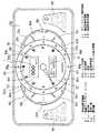
図1において、車両用表示装置1は、その正面の中央に、フルグラフィックメータ50が配置されている。また、このフルグラフィックメータ50の左右には、それぞれ、ウォーニング表示部91,92が配置されている。 In FIG. 1, the vehicle display device 1 has a full
フルグラフィックメータ50は、液晶ディスプレイ(以下、LCDと略記する。請求項中のディスプレイに相当)51と、LCD51の一部を覆う見返し板52と、LCD51および見返し板52の前面に配置されたリング部材53(請求項中の環状部材に相当)とを含む。LCD51は、見返し板52のほぼ長円状の開口部52aから露出する表示面51aを有しており、この表示面51aには、車両の走行状態を示す種々の情報を表示することができる。 The full
表示面51aのほぼ中央には、リング部材53が配置されている。リング部材53は、不透明なプラスチック材料から形成され、中央に形成された円形の開口部53aにはレンズ55が嵌合されている。レンズ55は、凸型、凹型等のいずれの形状のものでも良いが、ここでは凸型レンズを用いている。リング部材53には、ほぼ等間隔に12個のLED発光部81a〜81lが設けられている。 A
見返し板52で隠されている領域を除くLCD51の表示面51aにおける全表示領域の一部である第1の表示領域としての、リング部材53の開口部で囲まれたLCD51の表示領域には、車両の走行状態の計測量を示す略円形の文字板に相当する表示意匠56が表示される。 In the display area of the
この表示意匠56は、第1の車両関連情報としてのエンジン回転数を指示するためのタコメータであり、その外周付近にタコメータ用目盛が表示される。また、エンジンをかけた時の実際のエンジン回転数計測量に対応して回転してタコメータ用目盛を指示する指針57も表示される。表示意匠56と指針57の表示は、アナログ指示計器を構成する。 The
表示意匠56の中央付近には、タコメータ以外の他の情報表示を行う副表示領域58が設けられている。副表示領域58には、たとえば、車両の走行速度をデジタル表示するスピードメータを表示するスピードメータ表示領域59と、車両の走行距離をデジタル表示するオド/トリップメータを表示するオド/トリップメータ表示領域61とが設けられている。 Near the center of the
リング部材53の左側の外周と見返し板52とで囲まれたLCD51の表示面51aには、たとえば、エンジンオイルの油圧を指示する油圧計を表示する油圧計表示領域62と、エンジンオイルの油温を指示する油温計を表示する油温計表示領域63が設けられている。 On the
また、リング部材53の右側の外周と見返し板52とで囲まれたLCD51の表示面51aには、たとえば、ガソリン等の燃料残量を指示する燃料計を表示する燃料計表示領域64と、冷却水の温度を指示する水温計を表示する水温計表示領域65とが設けられている。 Further, on the
尚、この実施の形態では、LCD51の表示面51aにおける、表示意匠56、指針57、副表示領域58のスピードメータ表示領域59、オド/トリップメータ表示領域61によるアナログ指示計器の表示部分が、請求項中の表示面上の一部領域に相当し、これに、油圧計表示領域62と油温計表示領域63とを加えたものが、請求項中の車両の各種情報に相当する。 In this embodiment, the display portion of the analog indicator by the
さらに車両用表示装置1は、リング部材53をLCD51のほぼ長円形状の表示面51aの長軸方向に移動することができるように構成されている。 Further, the vehicular display device 1 is configured so that the
図2は、リング部材53をLCD51のほぼ長円状の画面のほぼ中央から右端に移動させた状態を示している。リング部材53の移動に同期して、表示意匠56の表示も画面中央から右端に移動し、移動停止時に、移動前と同様にリング部材53で囲まれて表示される。 FIG. 2 shows a state in which the
上述のリング部材53および表示意匠56表示の移動開始と同時に、LCD51の表示面51aの左側に表示されていた油圧計表示領域62および油温計表示領域63と、右側に表示されていた燃料計表示領域64および水温計表示領域65の各表示は消去される。そして、リング部材53および表示意匠56表示の移動後、画面の中央から左端にかけて少し広くなった画面スペースには、上述の各表示領域に表示されていた車両関連情報以外の車両関連情報が表示される。たとえば、図2においては、エンジンオイル残量(OIL LEVEL)、ブレーキ液残量(BRAKE FLUID)、冷却水残量(COOLANT)、排気温度(EXH−TEMP)、吸気温度(INT−TEMP)、ウォッシャ液残量(WASHER)等が表示される。 Simultaneously with the start of movement of the
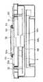
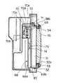
次に、リング部材53の移動を行わせる移動機構の構成について説明する。図3〜図5は、それぞれ、移動機構を説明するための車両用表示装置の正面透視図、底面透視図および左側面透視図である。移動機構67は、図5に示すように、リング部材53の移動用駆動源としてのモータ69と、このモータ69とリング部材53とを接続(駆動連結)する支持部材68とを有している。 Next, the configuration of a moving mechanism that moves the
支持部材68は、図3、5に示すように、LCD51のが実装される基板83の裏面側に上下に延在する基部68aと、基部68aの上下両端から図4に示すようにLCD51の前方に延出する一対の取付片68bとを有しており、図5に示すように、見返し板52の裏面側で見返し板52に沿って開口部52aの内側向きに折曲された各取付片68bの先端は、見返し板52の開口部52aに挿入されたリング部材53の後部小径部分の後端上部および下部に各々取り付けられている。モータ69は基板83に取り付けられている。 As shown in FIGS. 3 and 5, the
これにより、見返し板52の開口部52aに挿入されず見返し板52の前方に位置するリング部材53の前部大径部分と、支持部材68の各取付片68bの前端部分との間に、見返し板52の開口部52a寄り部分が配置されて、LCD51の表示面51aの前方に位置する取付片68bの前端部分が見返し板52により全て覆われることになる。 As a result, the counterclockwise portion between the front large-diameter portion of the
また、移動機構67は、上記した支持部材68及びモータ69の他に、モータ69の駆動力を支持部材68に伝える伝達装置70を含む。伝達装置70は、リング部材53の移動方向に沿ってLCD51の上部に固定配置されて、見返し板52の開口部52aの上縁に沿って延在するシャフト72と、このシャフト72にスライド可能に遊嵌されて支持部材68の上側の取付片68bに固定された第1支持部71と、基板83の裏面側にほぼ長円状表示面51aの長軸方向に平行に配置されたレール部材73と、支持部材68に固定され、レール部材73をガイドするガイド溝が形成された第2支持部74を含む。 In addition to the
また、伝達装置70は、モータ69の回転軸に固定された歯車70aと、歯車70aにかみ合う歯車70bと、歯車70bの回転がベルト70cで伝えられるピニオン歯車70dと、支持部材68の上側の取付片68bに固定され、ピニオン歯車70dの回転運動を長軸方向と平行な直線運動に変換するラック70eとを含む。 Further, the
そして、モータ69が駆動されると、ラック70eにより変換された直線運動が伝達される支持部材68の上側の取付片68bが、第1支持部71及びシャフト72に案内されて、見返し板52の開口部52aの上縁に沿って直線移動し、この上側の取付片68b及び下側の取付片68bに連結されたリング部材53が、見返し板52の開口部52aの上縁に沿って、モータ69の回転方向に応じた方向に直線移動される。 When the
尚、LCD51の表示制御やそれに連動してリング部材53を移動させるためのモータ69の駆動制御は、不図示のマイコンによって制御される。 The display control of the
この不図示のマイコンの制御によって、リング部材53は常に、LCD51の表示面51a上における、メインとなるエンジン回転数を示す表示意匠56の画像を取り囲む位置に配置される。 Under the control of the microcomputer (not shown), the
もし移動中に移動機構67の誤動作等により移動が中断されるようなトラブル時においても、リング部材53の位置と、表示意匠56および指針57の表示の位置はずれることなく、相変わらず、メインとなるエンジン回転数を示す表示意匠56の画像をリング部材53で取り囲み、他の領域の画像と区別して視認させることができる。 Even when the movement is interrupted due to a malfunction of the moving
このように構成された本実施の形態の車両用表示装置1では、リング部材53が、その直線移動方向である左右方向と直交しLCD51の表示面51aに沿う上下方向に間隔をおいた上部及び下部の後端において、支持部材68の各取付片68bによって左右方向に直線移動可能に支持されているので、リング部材53の直線移動方向である左右方向と直交する方向において、リング部材53がガタ付くのを防ぐことができる。 In the vehicular display device 1 according to the present embodiment configured as described above, the
しかも、リング部材53の前部大径部分と支持部材68の各取付片68bの前端部分との間に配置される見返し板52の開口部52a寄り部分によって、LCD51の表示面51aの前方に位置する取付片68bの前端部分が全て覆われるので、車両用表示装置1の前方からユーザがフルグラフィックメータ50を視認した際に、移動中のリング部材53のガタ付き防止に不可欠な支持部材68が露出して見えてしまうのを防ぎ、LCD51とリング部材53による、メリハリのある立体的な表示を確実に実現させることができる。 In addition, it is positioned in front of the
尚、上述の実施の形態では、駆動源としてのモータ69を基板側に固定しかつラック70eを支持部材68側に固定しているが、これに代えて、モータ69を支持部材68側に固定しかつラック70eを基板側に固定するように構成しても良い。 In the above-described embodiment, the
また、上述の実施の形態では、伝達装置70としてギヤベルトドライブ方式を採用しているが、これに限らず、スクリュードライブ方式や、ラック&ギアドライブ等の他の方式を採用することもできる。 In the above-described embodiment, the gear belt drive system is adopted as the
また、上述の実施の形態では、リング部材53の移動停止時、リング部材53の移動により空いた、表示意匠56が表示されていた第1の表示領域と、油圧計表示領域62および油温計表示領域63が消去された領域とを含む表示領域には、これらの車両関連情報以外の車両関連情報として、たとえば、図2に示すようにエンジンオイル残量(OIL LEVEL)、ブレーキ液残量(BRAKE FLUID)、冷却水残量(COOLANT)、排気温度(EXH−TEMP)、吸気温度(INT−TEMP)、ウォッシャ液残量(WASHER)等のバー表示66が表示されるが、これに代えて、ナビゲーションシステムのナビ画面やバックガイドモニタのモニタ画面等の表示を行うこともできる。 Further, in the above-described embodiment, when the movement of the
また、上述の第2の実施の形態では、ディスプレイとしてLCDを用いているが、本発明では、表示内容を電気プログラム的に変化させることができるものであれば、これに限らず、有機ELやプラズマディスプレイ等の他の表示素子を用いることができる。 In the second embodiment described above, an LCD is used as the display. However, the present invention is not limited to this, as long as the display content can be changed in an electric program, and the organic EL or Other display elements such as a plasma display can be used.
また、リング部材53は、円形に限らず、たとえば四角形等の多角形状や、円の一部が直線となっている形状などの、表示を仕切る環状の形状であれば良い。 The
また、上述の実施の形態では、車両用表示装置1を例に取って本発明を説明したが、本発明は車両用表示装置に限らず、ディスプレイの表示面の前方にその表示面に沿って直線移動可能に配置した環状部材により、ディスプレイの表示面上の一部領域を囲むように表示面の前方から視認させる構成の表示装置であれば、車両用以外の用途のものであっても適用可能である。 In the above-described embodiment, the present invention has been described by taking the vehicular display device 1 as an example. However, the present invention is not limited to the vehicular display device, and is along the display surface in front of the display surface of the display. Even if the display device is configured to be visually recognized from the front of the display surface so as to surround a partial area on the display surface of the display by an annular member arranged so as to be linearly movable, it is also applicable for applications other than those for vehicles. Is possible.
1 車両用表示装置
51 LCD(ディスプレイ)
51a 表示面
52 見返し板
52a 開口部
53 リング部材(環状部材)
56 表示意匠(一部領域、車両の走行状態の計測量を示す表示意匠)
57 指針(一部領域、車両の走行状態の計測量を示す表示意匠)
58 副表示領域(一部領域、車両の走行状態の計測量を示す表示意匠)
59 スピードメータ表示領域(一部領域、車両の走行状態の計測量を示す表示意匠)
61 オド/トリップメータ表示領域(一部領域、車両の走行状態の計測量を示す表示意匠)
62 油圧計表示領域(車両の各種情報)
63 油温計表示領域(車両の各種情報)
68 支持部材
69 モータ(移動用駆動源)1
56 display design (display design showing the measurement amount of the running state of the vehicle in a partial area)
57 Pointer (display design showing the measurement amount of the driving state of some areas and vehicles)
58 Auxiliary display area (partial area, display design showing the measured amount of the running state of the vehicle)
59 Speedometer display area (partial area, display design showing the measured amount of vehicle running state)
61 Od / trip meter display area (partial area, display design showing the measured amount of vehicle running state)
62 Hydraulic gauge display area (Vehicle information)
63 Oil temperature gauge display area (Vehicle information)
68
Claims (2)
Translated fromJapanese前記ディスプレイの後方に配置された前記環状部材の移動用駆動源と、
前記環状部材の直線移動方向と交わり前記表示面に沿う方向に間隔をおいた二つの環状部材部分と前記移動用駆動源とを接続する支持部材とを備え、
前記支持部材は、前記各環状部材部分から前記環状部材の外側に延出し前記ディスプレイの外側を通って前記移動用駆動源に至るように形成されており、
前記見返し板は、前記表示面を露出させる該見返し板の開口部の周縁部分が、前記環状部材の前後方向において、前記各環状部材部分と前記支持部材との間に配置されるように構成されている、
ことを特徴とする表示装置。The display so as to surround a partial region on the display surface by an annular member arranged so as to be linearly movable along the display surface in front of the display surface of the display whose outer surface is covered with a facing plate. A display device that is visible from the front of the surface,
A driving source for moving the annular member disposed behind the display;
A support member for connecting the two drive members for movement and two annular member portions that intersect the linear movement direction of the annular member and are spaced in the direction along the display surface;
The support member is formed so as to extend from each annular member portion to the outside of the annular member and to reach the driving source for movement through the outside of the display.
The facing plate is configured such that a peripheral portion of the opening portion of the facing plate that exposes the display surface is disposed between each annular member portion and the support member in the front-rear direction of the annular member. ing,
A display device characterized by that.
Priority Applications (2)
| Application Number | Priority Date | Filing Date | Title |
|---|---|---|---|
| JP2005227098AJP4805630B2 (en) | 2005-08-04 | 2005-08-04 | Display device |
| US11/494,554US7586404B2 (en) | 2005-08-04 | 2006-07-28 | Display apparatus |
Applications Claiming Priority (1)
| Application Number | Priority Date | Filing Date | Title |
|---|---|---|---|
| JP2005227098AJP4805630B2 (en) | 2005-08-04 | 2005-08-04 | Display device |
Publications (2)
| Publication Number | Publication Date |
|---|---|
| JP2007041409A JP2007041409A (en) | 2007-02-15 |
| JP4805630B2true JP4805630B2 (en) | 2011-11-02 |
Family
ID=37766586
Family Applications (1)
| Application Number | Title | Priority Date | Filing Date |
|---|---|---|---|
| JP2005227098AExpired - LifetimeJP4805630B2 (en) | 2005-08-04 | 2005-08-04 | Display device |
Country Status (2)
| Country | Link |
|---|---|
| US (1) | US7586404B2 (en) |
| JP (1) | JP4805630B2 (en) |
Families Citing this family (14)
| Publication number | Priority date | Publication date | Assignee | Title |
|---|---|---|---|---|
| US7876235B2 (en)* | 2004-06-11 | 2011-01-25 | Johnson Controls Technology Company | Vehicle indicator assembly |
| US8281241B2 (en) | 2004-06-28 | 2012-10-02 | Nokia Corporation | Electronic device and method for providing extended user interface |
| JP5022761B2 (en)* | 2006-07-28 | 2012-09-12 | 矢崎総業株式会社 | Vehicle display device |
| JP5366525B2 (en)* | 2008-12-09 | 2013-12-11 | 矢崎総業株式会社 | Scale switching control method for vehicle instrument, and vehicle instrument |
| FR2948470B1 (en)* | 2009-07-21 | 2011-09-16 | Valeo Systemes Thermiques | METHOD FOR MANUFACTURING A MAN / MACHINE INTERFACE FOR A MOTOR VEHICLE AND MAN / MACHINE INTERFACE FOR THIS METHOD |
| DE102009056186B4 (en)* | 2009-11-27 | 2012-04-19 | Audi Ag | Operating device in a motor vehicle |
| JP5939435B2 (en)* | 2011-12-12 | 2016-06-22 | 日本精機株式会社 | Vehicle display device |
| JP5992704B2 (en)* | 2012-03-23 | 2016-09-14 | 矢崎総業株式会社 | Vehicle display device |
| JP5993189B2 (en)* | 2012-04-12 | 2016-09-14 | 矢崎総業株式会社 | Meter device |
| USD709092S1 (en)* | 2012-11-30 | 2014-07-15 | Google Inc. | Portion of a display screen with icon |
| JP6194214B2 (en)* | 2013-09-24 | 2017-09-06 | 矢崎総業株式会社 | Vehicle instrumentation |
| DE102013019565B4 (en) | 2013-11-22 | 2019-07-04 | Audi Ag | instrument cluster |
| USD752623S1 (en)* | 2014-09-01 | 2016-03-29 | Apple Inc. | Display screen or portion thereof with graphical user interface |
| JP6595930B2 (en)* | 2016-02-17 | 2019-10-23 | 矢崎総業株式会社 | Vehicle display system |
Family Cites Families (11)
| Publication number | Priority date | Publication date | Assignee | Title |
|---|---|---|---|---|
| JPS6258112A (en) | 1985-09-09 | 1987-03-13 | Mazda Motor Corp | Vehicle multiple display device |
| DE4240465A1 (en)* | 1992-12-02 | 1994-06-09 | Vdo Schindling | Combination instrument for vehicle dashboard - has primary tachometer display displaced from original position for viewing partially overlapped secondary liquid crystal display |
| JPH11248490A (en) | 1998-02-27 | 1999-09-17 | Yazaki Corp | LCD multiple display instrument |
| JP3529029B2 (en)* | 1998-07-21 | 2004-05-24 | 矢崎総業株式会社 | Display device for vehicles |
| JP2002292032A (en)* | 2001-03-30 | 2002-10-08 | Daiichi Shokai Co Ltd | Gaming machine equipped with a symbol display device |
| JP2004074871A (en)* | 2002-08-13 | 2004-03-11 | Kawasaki Heavy Ind Ltd | Display for vehicle |
| US7671859B2 (en)* | 2002-11-06 | 2010-03-02 | Continental Automotive Systems Us, Inc. | Thin instrument cluster with anti-reflective coating |
| DE102005003920B4 (en)* | 2004-01-28 | 2017-01-26 | Yazaki Corporation | display unit |
| JP4568087B2 (en)* | 2004-01-28 | 2010-10-27 | 矢崎総業株式会社 | Vehicle display device |
| JP4648681B2 (en)* | 2004-11-02 | 2011-03-09 | 矢崎総業株式会社 | Vehicle display device |
| DE102005042695B4 (en)* | 2004-12-30 | 2018-01-25 | Volkswagen Ag | Motor vehicle with a display device |
- 2005
- 2005-08-04JPJP2005227098Apatent/JP4805630B2/ennot_activeExpired - Lifetime
- 2006
- 2006-07-28USUS11/494,554patent/US7586404B2/enactiveActive
Also Published As
| Publication number | Publication date |
|---|---|
| US20070040072A1 (en) | 2007-02-22 |
| JP2007041409A (en) | 2007-02-15 |
| US7586404B2 (en) | 2009-09-08 |
Similar Documents
| Publication | Publication Date | Title |
|---|---|---|
| JP4805630B2 (en) | Display device | |
| JP4568087B2 (en) | Vehicle display device | |
| JP4648681B2 (en) | Vehicle display device | |
| JP5594525B2 (en) | Vehicle meter unit | |
| US10363818B2 (en) | Display unit for vehicle | |
| JP4504934B2 (en) | Vehicle display device | |
| JP2011017723A (en) | Display device for vehicle | |
| JP4235002B2 (en) | Vehicle display device | |
| JP2017181555A (en) | Display device | |
| JP2008265512A (en) | Vehicular display device | |
| JP4244937B2 (en) | Display device | |
| JP2015143710A (en) | Meter unit for vehicle | |
| JPH06262964A (en) | Display device for car | |
| JP5634678B2 (en) | Vehicle display device | |
| JP2005241627A (en) | Vehicle display device | |
| JP6237658B2 (en) | Vehicle display device | |
| JP4309647B2 (en) | Vehicle display device | |
| JP2008261725A (en) | Vehicle display device | |
| JP5131644B2 (en) | Display device | |
| JP2004069514A (en) | Display device for vehicles | |
| JP4499492B2 (en) | Vehicle display device | |
| JP6179380B2 (en) | Vehicle display device | |
| JP2004045214A (en) | Display device for vehicles | |
| JP5939772B2 (en) | Vehicle display device | |
| JP6056244B2 (en) | Pointer-type instrument device |
Legal Events
| Date | Code | Title | Description |
|---|---|---|---|
| A621 | Written request for application examination | Free format text:JAPANESE INTERMEDIATE CODE: A621 Effective date:20080804 | |
| TRDD | Decision of grant or rejection written | ||
| A01 | Written decision to grant a patent or to grant a registration (utility model) | Free format text:JAPANESE INTERMEDIATE CODE: A01 Effective date:20110809 | |
| A01 | Written decision to grant a patent or to grant a registration (utility model) | Free format text:JAPANESE INTERMEDIATE CODE: A01 | |
| A61 | First payment of annual fees (during grant procedure) | Free format text:JAPANESE INTERMEDIATE CODE: A61 Effective date:20110811 | |
| R150 | Certificate of patent or registration of utility model | Ref document number:4805630 Country of ref document:JP Free format text:JAPANESE INTERMEDIATE CODE: R150 Free format text:JAPANESE INTERMEDIATE CODE: R150 | |
| FPAY | Renewal fee payment (event date is renewal date of database) | Free format text:PAYMENT UNTIL: 20140819 Year of fee payment:3 | |
| R250 | Receipt of annual fees | Free format text:JAPANESE INTERMEDIATE CODE: R250 | |
| R250 | Receipt of annual fees | Free format text:JAPANESE INTERMEDIATE CODE: R250 | |
| R250 | Receipt of annual fees | Free format text:JAPANESE INTERMEDIATE CODE: R250 | |
| R250 | Receipt of annual fees | Free format text:JAPANESE INTERMEDIATE CODE: R250 | |
| R250 | Receipt of annual fees | Free format text:JAPANESE INTERMEDIATE CODE: R250 | |
| R250 | Receipt of annual fees | Free format text:JAPANESE INTERMEDIATE CODE: R250 | |
| R250 | Receipt of annual fees | Free format text:JAPANESE INTERMEDIATE CODE: R250 | |
| S531 | Written request for registration of change of domicile | Free format text:JAPANESE INTERMEDIATE CODE: R313531 | |
| R350 | Written notification of registration of transfer | Free format text:JAPANESE INTERMEDIATE CODE: R350 | |
| R250 | Receipt of annual fees | Free format text:JAPANESE INTERMEDIATE CODE: R250 | |
| R250 | Receipt of annual fees | Free format text:JAPANESE INTERMEDIATE CODE: R250 |