JP4799627B2 - Drug dispensing device rotating for priming and pulling / pushing for injection function - Google Patents
Drug dispensing device rotating for priming and pulling / pushing for injection functionDownload PDFInfo
- Publication number
- JP4799627B2 JP4799627B2JP2009027242AJP2009027242AJP4799627B2JP 4799627 B2JP4799627 B2JP 4799627B2JP 2009027242 AJP2009027242 AJP 2009027242AJP 2009027242 AJP2009027242 AJP 2009027242AJP 4799627 B2JP4799627 B2JP 4799627B2
- Authority
- JP
- Japan
- Prior art keywords
- drive
- follower
- housing
- priming
- dispensing device
- Prior art date
- Legal status (The legal status is an assumption and is not a legal conclusion. Google has not performed a legal analysis and makes no representation as to the accuracy of the status listed.)
- Expired - Fee Related
Links
- 239000003814drugSubstances0.000titleclaimsabstractdescription134
- 229940079593drugDrugs0.000titleclaimsabstractdescription129
- 230000037452primingEffects0.000titleclaimsabstractdescription90
- 238000002347injectionMethods0.000titledescription116
- 239000007924injectionSubstances0.000titledescription116
- 230000007246mechanismEffects0.000claimsabstractdescription40
- 239000012530fluidSubstances0.000claimsdescription33
- 230000000903blocking effectEffects0.000claims2
- 238000005452bendingMethods0.000claims1
- 238000012377drug deliveryMethods0.000claims1
- 210000003811fingerAnatomy0.000description121
- 230000006870functionEffects0.000description15
- 230000008901benefitEffects0.000description14
- 238000013461designMethods0.000description14
- 238000004519manufacturing processMethods0.000description14
- 230000002829reductive effectEffects0.000description12
- 229920003023plasticPolymers0.000description11
- 239000004033plasticSubstances0.000description10
- 210000000078clawAnatomy0.000description9
- 238000000034methodMethods0.000description7
- 239000004417polycarbonateSubstances0.000description6
- 229920000515polycarbonatePolymers0.000description6
- 230000009471actionEffects0.000description5
- 238000003780insertionMethods0.000description5
- 239000000463materialSubstances0.000description5
- 230000004323axial lengthEffects0.000description4
- 230000008859changeEffects0.000description4
- 230000008878couplingEffects0.000description4
- 238000010168coupling processMethods0.000description4
- 238000005859coupling reactionMethods0.000description4
- 230000037431insertionEffects0.000description4
- 230000002265preventionEffects0.000description4
- 230000008569processEffects0.000description4
- DHKHKXVYLBGOIT-UHFFFAOYSA-Nacetaldehyde Diethyl AcetalNatural productsCCOC(C)OCCDHKHKXVYLBGOIT-UHFFFAOYSA-N0.000description3
- 125000002777acetyl groupChemical class[H]C([H])([H])C(*)=O0.000description3
- 230000006835compressionEffects0.000description3
- 238000007906compressionMethods0.000description3
- 230000007935neutral effectEffects0.000description3
- 230000036961partial effectEffects0.000description3
- 239000000853adhesiveSubstances0.000description2
- 230000001070adhesive effectEffects0.000description2
- 230000000712assemblyEffects0.000description2
- 238000000429assemblyMethods0.000description2
- 210000000746body regionAnatomy0.000description2
- 238000004891communicationMethods0.000description2
- 230000007812deficiencyEffects0.000description2
- 239000003562lightweight materialSubstances0.000description2
- 239000002184metalSubstances0.000description2
- 230000001681protective effectEffects0.000description2
- 230000000087stabilizing effectEffects0.000description2
- 210000003813thumbAnatomy0.000description2
- 239000002699waste materialSubstances0.000description2
- 101800000224Glucagon-like peptide 1Proteins0.000description1
- DTHNMHAUYICORS-KTKZVXAJSA-NGlucagon-like peptide 1Chemical compoundC([C@@H](C(=O)N[C@@H]([C@@H](C)CC)C(=O)N[C@@H](C)C(=O)N[C@@H](CC=1C2=CC=CC=C2NC=1)C(=O)N[C@@H](CC(C)C)C(=O)N[C@@H](C(C)C)C(=O)N[C@@H](CCCCN)C(=O)NCC(=O)N[C@@H](CCCNC(N)=N)C(N)=O)NC(=O)[C@H](CCC(O)=O)NC(=O)[C@H](CCCCN)NC(=O)[C@H](C)NC(=O)[C@H](C)NC(=O)[C@H](CCC(N)=O)NC(=O)CNC(=O)[C@H](CCC(O)=O)NC(=O)[C@H](CC(C)C)NC(=O)[C@H](CC=1C=CC(O)=CC=1)NC(=O)[C@H](CO)NC(=O)[C@H](CO)NC(=O)[C@@H](NC(=O)[C@H](CC(O)=O)NC(=O)[C@H](CO)NC(=O)[C@@H](NC(=O)[C@H](CC=1C=CC=CC=1)NC(=O)[C@@H](NC(=O)CNC(=O)[C@H](CCC(O)=O)NC(=O)[C@H](C)NC(=O)[C@@H](N)CC=1N=CNC=1)[C@@H](C)O)[C@@H](C)O)C(C)C)C1=CC=CC=C1DTHNMHAUYICORS-KTKZVXAJSA-N0.000description1
- 101800004266Glucagon-like peptide 1(7-37)Proteins0.000description1
- 102100040918Pro-glucagonHuman genes0.000description1
- 230000006978adaptationEffects0.000description1
- 230000002411adverseEffects0.000description1
- 230000003416augmentationEffects0.000description1
- 230000008602contractionEffects0.000description1
- 230000003247decreasing effectEffects0.000description1
- 230000002950deficientEffects0.000description1
- 230000008021depositionEffects0.000description1
- 206010012601diabetes mellitusDiseases0.000description1
- 239000011521glassSubstances0.000description1
- 230000000670limiting effectEffects0.000description1
- 239000007788liquidSubstances0.000description1
- 230000013011matingEffects0.000description1
- 238000002483medicationMethods0.000description1
- 230000004048modificationEffects0.000description1
- 238000012986modificationMethods0.000description1
- 238000000465mouldingMethods0.000description1
- 238000005192partitionMethods0.000description1
- 238000002360preparation methodMethods0.000description1
- GCYXWQUSHADNBF-AAEALURTSA-Npreproglucagon 78-108Chemical compoundC([C@@H](C(=O)N[C@@H]([C@@H](C)CC)C(=O)N[C@@H](C)C(=O)N[C@@H](CC=1C2=CC=CC=C2NC=1)C(=O)N[C@@H](CC(C)C)C(=O)N[C@@H](C(C)C)C(=O)N[C@@H](CCCCN)C(=O)NCC(=O)N[C@@H](CCCNC(N)=N)C(=O)NCC(O)=O)NC(=O)[C@H](CCC(O)=O)NC(=O)[C@H](CCCCN)NC(=O)[C@H](C)NC(=O)[C@H](C)NC(=O)[C@H](CCC(N)=O)NC(=O)CNC(=O)[C@H](CCC(O)=O)NC(=O)[C@H](CC(C)C)NC(=O)[C@H](CC=1C=CC(O)=CC=1)NC(=O)[C@H](CO)NC(=O)[C@H](CO)NC(=O)[C@@H](NC(=O)[C@H](CC(O)=O)NC(=O)[C@H](CO)NC(=O)[C@@H](NC(=O)[C@H](CC=1C=CC=CC=1)NC(=O)[C@@H](NC(=O)CNC(=O)[C@H](CCC(O)=O)NC(=O)[C@H](C)NC(=O)[C@@H](N)CC=1N=CNC=1)[C@@H](C)O)[C@@H](C)O)C(C)C)C1=CC=CC=C1GCYXWQUSHADNBF-AAEALURTSA-N0.000description1
- 238000003825pressingMethods0.000description1
- 239000012925reference materialSubstances0.000description1
- 230000002787reinforcementEffects0.000description1
- 230000002441reversible effectEffects0.000description1
- 238000000926separation methodMethods0.000description1
- 230000007480spreadingEffects0.000description1
- 238000003892spreadingMethods0.000description1
- 230000007704transitionEffects0.000description1
- 238000003466weldingMethods0.000description1
Images


Classifications
- A—HUMAN NECESSITIES
- A61—MEDICAL OR VETERINARY SCIENCE; HYGIENE
- A61M—DEVICES FOR INTRODUCING MEDIA INTO, OR ONTO, THE BODY; DEVICES FOR TRANSDUCING BODY MEDIA OR FOR TAKING MEDIA FROM THE BODY; DEVICES FOR PRODUCING OR ENDING SLEEP OR STUPOR
- A61M5/00—Devices for bringing media into the body in a subcutaneous, intra-vascular or intramuscular way; Accessories therefor, e.g. filling or cleaning devices, arm-rests
- A61M5/178—Syringes
- A61M5/31—Details
- A61M5/315—Pistons; Piston-rods; Guiding, blocking or restricting the movement of the rod or piston; Appliances on the rod for facilitating dosing ; Dosing mechanisms
- A61M5/31565—Administration mechanisms, i.e. constructional features, modes of administering a dose
- A61M5/31576—Constructional features or modes of drive mechanisms for piston rods
- A61M5/31578—Constructional features or modes of drive mechanisms for piston rods based on axial translation, i.e. components directly operatively associated and axially moved with plunger rod
- A61M5/3158—Constructional features or modes of drive mechanisms for piston rods based on axial translation, i.e. components directly operatively associated and axially moved with plunger rod performed by axially moving actuator operated by user, e.g. an injection button
- A—HUMAN NECESSITIES
- A61—MEDICAL OR VETERINARY SCIENCE; HYGIENE
- A61M—DEVICES FOR INTRODUCING MEDIA INTO, OR ONTO, THE BODY; DEVICES FOR TRANSDUCING BODY MEDIA OR FOR TAKING MEDIA FROM THE BODY; DEVICES FOR PRODUCING OR ENDING SLEEP OR STUPOR
- A61M5/00—Devices for bringing media into the body in a subcutaneous, intra-vascular or intramuscular way; Accessories therefor, e.g. filling or cleaning devices, arm-rests
- A61M5/178—Syringes
- A61M5/24—Ampoule syringes, i.e. syringes with needle for use in combination with replaceable ampoules or carpules, e.g. automatic
- A61M2005/2403—Ampoule inserted into the ampoule holder
- A61M2005/2407—Ampoule inserted into the ampoule holder from the rear
- A—HUMAN NECESSITIES
- A61—MEDICAL OR VETERINARY SCIENCE; HYGIENE
- A61M—DEVICES FOR INTRODUCING MEDIA INTO, OR ONTO, THE BODY; DEVICES FOR TRANSDUCING BODY MEDIA OR FOR TAKING MEDIA FROM THE BODY; DEVICES FOR PRODUCING OR ENDING SLEEP OR STUPOR
- A61M5/00—Devices for bringing media into the body in a subcutaneous, intra-vascular or intramuscular way; Accessories therefor, e.g. filling or cleaning devices, arm-rests
- A61M5/178—Syringes
- A61M5/24—Ampoule syringes, i.e. syringes with needle for use in combination with replaceable ampoules or carpules, e.g. automatic
- A61M2005/2485—Ampoule holder connected to rest of syringe
- A61M2005/2488—Ampoule holder connected to rest of syringe via rotation, e.g. threads or bayonet
- A—HUMAN NECESSITIES
- A61—MEDICAL OR VETERINARY SCIENCE; HYGIENE
- A61M—DEVICES FOR INTRODUCING MEDIA INTO, OR ONTO, THE BODY; DEVICES FOR TRANSDUCING BODY MEDIA OR FOR TAKING MEDIA FROM THE BODY; DEVICES FOR PRODUCING OR ENDING SLEEP OR STUPOR
- A61M5/00—Devices for bringing media into the body in a subcutaneous, intra-vascular or intramuscular way; Accessories therefor, e.g. filling or cleaning devices, arm-rests
- A61M5/178—Syringes
- A61M5/31—Details
- A61M2005/3123—Details having air entrapping or venting means, e.g. purging channels in pistons
- A—HUMAN NECESSITIES
- A61—MEDICAL OR VETERINARY SCIENCE; HYGIENE
- A61M—DEVICES FOR INTRODUCING MEDIA INTO, OR ONTO, THE BODY; DEVICES FOR TRANSDUCING BODY MEDIA OR FOR TAKING MEDIA FROM THE BODY; DEVICES FOR PRODUCING OR ENDING SLEEP OR STUPOR
- A61M5/00—Devices for bringing media into the body in a subcutaneous, intra-vascular or intramuscular way; Accessories therefor, e.g. filling or cleaning devices, arm-rests
- A61M5/178—Syringes
- A61M5/24—Ampoule syringes, i.e. syringes with needle for use in combination with replaceable ampoules or carpules, e.g. automatic
- A—HUMAN NECESSITIES
- A61—MEDICAL OR VETERINARY SCIENCE; HYGIENE
- A61M—DEVICES FOR INTRODUCING MEDIA INTO, OR ONTO, THE BODY; DEVICES FOR TRANSDUCING BODY MEDIA OR FOR TAKING MEDIA FROM THE BODY; DEVICES FOR PRODUCING OR ENDING SLEEP OR STUPOR
- A61M5/00—Devices for bringing media into the body in a subcutaneous, intra-vascular or intramuscular way; Accessories therefor, e.g. filling or cleaning devices, arm-rests
- A61M5/178—Syringes
- A61M5/31—Details
- A61M5/3146—Priming, e.g. purging, reducing backlash or clearance
- A—HUMAN NECESSITIES
- A61—MEDICAL OR VETERINARY SCIENCE; HYGIENE
- A61M—DEVICES FOR INTRODUCING MEDIA INTO, OR ONTO, THE BODY; DEVICES FOR TRANSDUCING BODY MEDIA OR FOR TAKING MEDIA FROM THE BODY; DEVICES FOR PRODUCING OR ENDING SLEEP OR STUPOR
- A61M5/00—Devices for bringing media into the body in a subcutaneous, intra-vascular or intramuscular way; Accessories therefor, e.g. filling or cleaning devices, arm-rests
- A61M5/178—Syringes
- A61M5/31—Details
- A61M5/315—Pistons; Piston-rods; Guiding, blocking or restricting the movement of the rod or piston; Appliances on the rod for facilitating dosing ; Dosing mechanisms
- A61M5/31511—Piston or piston-rod constructions, e.g. connection of piston with piston-rod
- A—HUMAN NECESSITIES
- A61—MEDICAL OR VETERINARY SCIENCE; HYGIENE
- A61M—DEVICES FOR INTRODUCING MEDIA INTO, OR ONTO, THE BODY; DEVICES FOR TRANSDUCING BODY MEDIA OR FOR TAKING MEDIA FROM THE BODY; DEVICES FOR PRODUCING OR ENDING SLEEP OR STUPOR
- A61M5/00—Devices for bringing media into the body in a subcutaneous, intra-vascular or intramuscular way; Accessories therefor, e.g. filling or cleaning devices, arm-rests
- A61M5/178—Syringes
- A61M5/31—Details
- A61M5/315—Pistons; Piston-rods; Guiding, blocking or restricting the movement of the rod or piston; Appliances on the rod for facilitating dosing ; Dosing mechanisms
- A61M5/31533—Dosing mechanisms, i.e. setting a dose
- A61M5/31535—Means improving security or handling thereof, e.g. blocking means, means preventing insufficient dosing, means allowing correction of overset dose
- A61M5/31541—Means preventing setting of a dose beyond the amount remaining in the cartridge
- A—HUMAN NECESSITIES
- A61—MEDICAL OR VETERINARY SCIENCE; HYGIENE
- A61M—DEVICES FOR INTRODUCING MEDIA INTO, OR ONTO, THE BODY; DEVICES FOR TRANSDUCING BODY MEDIA OR FOR TAKING MEDIA FROM THE BODY; DEVICES FOR PRODUCING OR ENDING SLEEP OR STUPOR
- A61M5/00—Devices for bringing media into the body in a subcutaneous, intra-vascular or intramuscular way; Accessories therefor, e.g. filling or cleaning devices, arm-rests
- A61M5/178—Syringes
- A61M5/31—Details
- A61M5/315—Pistons; Piston-rods; Guiding, blocking or restricting the movement of the rod or piston; Appliances on the rod for facilitating dosing ; Dosing mechanisms
- A61M5/31533—Dosing mechanisms, i.e. setting a dose
- A61M5/31535—Means improving security or handling thereof, e.g. blocking means, means preventing insufficient dosing, means allowing correction of overset dose
- A61M5/31543—Means improving security or handling thereof, e.g. blocking means, means preventing insufficient dosing, means allowing correction of overset dose piston rod reset means, i.e. means for causing or facilitating retraction of piston rod to its starting position during cartridge change
- A—HUMAN NECESSITIES
- A61—MEDICAL OR VETERINARY SCIENCE; HYGIENE
- A61M—DEVICES FOR INTRODUCING MEDIA INTO, OR ONTO, THE BODY; DEVICES FOR TRANSDUCING BODY MEDIA OR FOR TAKING MEDIA FROM THE BODY; DEVICES FOR PRODUCING OR ENDING SLEEP OR STUPOR
- A61M5/00—Devices for bringing media into the body in a subcutaneous, intra-vascular or intramuscular way; Accessories therefor, e.g. filling or cleaning devices, arm-rests
- A61M5/178—Syringes
- A61M5/31—Details
- A61M5/315—Pistons; Piston-rods; Guiding, blocking or restricting the movement of the rod or piston; Appliances on the rod for facilitating dosing ; Dosing mechanisms
- A61M5/31533—Dosing mechanisms, i.e. setting a dose
- A61M5/31545—Setting modes for dosing
- A61M5/31548—Mechanically operated dose setting member
- A61M5/31555—Mechanically operated dose setting member by purely axial movement of dose setting member, e.g. during setting or filling of a syringe
- A—HUMAN NECESSITIES
- A61—MEDICAL OR VETERINARY SCIENCE; HYGIENE
- A61M—DEVICES FOR INTRODUCING MEDIA INTO, OR ONTO, THE BODY; DEVICES FOR TRANSDUCING BODY MEDIA OR FOR TAKING MEDIA FROM THE BODY; DEVICES FOR PRODUCING OR ENDING SLEEP OR STUPOR
- A61M5/00—Devices for bringing media into the body in a subcutaneous, intra-vascular or intramuscular way; Accessories therefor, e.g. filling or cleaning devices, arm-rests
- A61M5/178—Syringes
- A61M5/31—Details
- A61M5/315—Pistons; Piston-rods; Guiding, blocking or restricting the movement of the rod or piston; Appliances on the rod for facilitating dosing ; Dosing mechanisms
- A61M5/31533—Dosing mechanisms, i.e. setting a dose
- A61M5/31545—Setting modes for dosing
- A61M5/31548—Mechanically operated dose setting member
- A61M5/31561—Mechanically operated dose setting member using freely adjustable volume steps
- A—HUMAN NECESSITIES
- A61—MEDICAL OR VETERINARY SCIENCE; HYGIENE
- A61M—DEVICES FOR INTRODUCING MEDIA INTO, OR ONTO, THE BODY; DEVICES FOR TRANSDUCING BODY MEDIA OR FOR TAKING MEDIA FROM THE BODY; DEVICES FOR PRODUCING OR ENDING SLEEP OR STUPOR
- A61M5/00—Devices for bringing media into the body in a subcutaneous, intra-vascular or intramuscular way; Accessories therefor, e.g. filling or cleaning devices, arm-rests
- A61M5/178—Syringes
- A61M5/31—Details
- A61M5/315—Pistons; Piston-rods; Guiding, blocking or restricting the movement of the rod or piston; Appliances on the rod for facilitating dosing ; Dosing mechanisms
- A61M5/31565—Administration mechanisms, i.e. constructional features, modes of administering a dose
- A61M5/3159—Dose expelling manners
- A61M5/31593—Multi-dose, i.e. individually set dose repeatedly administered from the same medicament reservoir
- A61M5/31595—Pre-defined multi-dose administration by repeated overcoming of means blocking the free advancing movement of piston rod, e.g. by tearing or de-blocking
- A—HUMAN NECESSITIES
- A61—MEDICAL OR VETERINARY SCIENCE; HYGIENE
- A61M—DEVICES FOR INTRODUCING MEDIA INTO, OR ONTO, THE BODY; DEVICES FOR TRANSDUCING BODY MEDIA OR FOR TAKING MEDIA FROM THE BODY; DEVICES FOR PRODUCING OR ENDING SLEEP OR STUPOR
- A61M5/00—Devices for bringing media into the body in a subcutaneous, intra-vascular or intramuscular way; Accessories therefor, e.g. filling or cleaning devices, arm-rests
- A61M5/46—Devices for bringing media into the body in a subcutaneous, intra-vascular or intramuscular way; Accessories therefor, e.g. filling or cleaning devices, arm-rests having means for controlling depth of insertion
Landscapes
- Health & Medical Sciences (AREA)
- Vascular Medicine (AREA)
- Engineering & Computer Science (AREA)
- Anesthesiology (AREA)
- Biomedical Technology (AREA)
- Heart & Thoracic Surgery (AREA)
- Hematology (AREA)
- Life Sciences & Earth Sciences (AREA)
- Animal Behavior & Ethology (AREA)
- General Health & Medical Sciences (AREA)
- Public Health (AREA)
- Veterinary Medicine (AREA)
- Infusion, Injection, And Reservoir Apparatuses (AREA)
- Medicines That Contain Protein Lipid Enzymes And Other Medicines (AREA)
Abstract
Description
Translated fromJapanese本発明は、薬物投薬器具、特に、注射ペンのような携帯式薬物投薬器具に関する。 The present invention relates to drug dispensing devices, particularly portable drug dispensing devices such as injection pens.
多数の異なる病気を患っている患者は、しばしば薬物を自分で注射しなければならない。人が便利にかつ正確に薬剤を自己投与できるようにするために、注射器ペンまたは注射ペンとして広く知られている各種の器具が、開発されてきた。一般に、そのようなペンは、ピストンを備えかつ液体薬物の複数回服用量を収容したカートリッジを装備している。駆動部材であって、注射器ペンのベース内から伸び、且つ、典型的には該駆動部材の動きを制御するペンの、より後方の機構に動作可能に連結されている、駆動部材は、内包薬物を反対側のカートリッジ端の出口から投薬、典型的には、上記反対側端のストッパーを貫通している針を通じて投薬するように、カートリッジ内のピストンを前進させるために前方へ可動である。使い捨てペンにおいて、ペンが、使用されてカートリッジ内の薬物供給量を使い尽くした後、ペン全体が、その後、新しく取り替えられたペンの使用を始めるユーザーによって、捨てられる。再使用可能ペンにおいて、ペンが、使用されてカートリッジ内の薬物供給量を使い尽くした後、該ペンは、使い尽くされたカートリッジを新しいカートリッジと取り替えるために分解され、その後、ペンは、次の使用のために再び組み立てられる。 Patients with many different illnesses often have to inject the drug themselves. Various devices, commonly known as syringe pens or injection pens, have been developed to allow a person to conveniently and accurately self-administer medication. In general, such pens are equipped with a cartridge with a piston and containing multiple doses of liquid drug. A drive member extending from within the base of the syringe pen and typically operably connected to a rearward mechanism of the pen that controls movement of the drive member is the encapsulated drug. Is movable forward to advance the piston in the cartridge to dispense from the outlet at the opposite cartridge end, typically through a needle that penetrates the stopper at the opposite end. In a disposable pen, after the pen has been used and used up the drug supply in the cartridge, the entire pen is then discarded by the user starting to use the newly replaced pen. In a reusable pen, after the pen has been used and used up the drug supply in the cartridge, the pen is disassembled to replace the exhausted cartridge with a new cartridge, after which the pen Reassembled for use.
注射器ペンが最適に使用されるため、ユーザーは、薬剤を自分に注射するためにペンを使用する直前に、ペンをプライミングしなければならない。プライミング中、空気をカートリッジと針とから押し出し、且つ、薬剤を針の露出されている先端または前方の端に到達させるため、ペンは、カートリッジピストンを充分な距離だけシフトするように動作され、これによって、ペンの次の注射使用によって、実際に、薬剤量が放出されるように、ペンが準備される。しかしながら、あるユーザーは、ペンをそのようにプライミングすることを怠り、ユーザーにより予測意図されたよりも少ない薬剤の注射を来す。 Because syringe pens are optimally used, the user must prime the pen just prior to using the pen to inject the drug into himself. During priming, the pen is operated to shift the cartridge piston a sufficient distance in order to push air out of the cartridge and needle and allow the drug to reach the exposed or forward end of the needle. The pen is then prepared such that the drug dose is actually released by the next injection use of the pen. However, some users fail to prime their pens in that way, resulting in fewer drug injections than expected by the user.
プライミング失敗について可能な説明のひとつは、殆どの注射器ペンの設計が、服用量注射ステップからプライミングステップをユーザーが概念的に識別することを助けないことである。特に、該プライミングステップは、典型的には、ペンを、少量を放出するためにセッテイングすることと、ペンを、注射するのではないが、ユーザーが注射する間に実施するのと同じように操作することと、それから、もし必要であれば、プライミングが達成されるまで、これらのステップを繰り返すことと、を備えている。それから、服用量注射ステップ中、服用量は、プライミングステップと全く同様に、実際にセットされるが、典型的には、より多い量にセットされ、それからペンは、薬剤をユーザーに注射するのに使用される。 One possible explanation for priming failure is that most syringe pen designs do not help the user conceptually distinguish the priming step from the dose injection step. In particular, the priming step typically involves setting up the pen to release a small amount and operating the pen as if it were performed while the user did not inject, but did inject. And then, if necessary, repeating these steps until priming is achieved. Then, during the dose injection step, the dose is actually set, just like the priming step, but is typically set to a larger amount, and then the pen is used to inject the drug into the user. used.
米国特許第5961495号は、注射ペンを開示している。その中でプライミング制御機構は、外側からの視認によるものであり、実際にセットし、かつ選択された服用量をユーザー内に注射するのに使用される機構とは別個のものである。服用量セッテイングおよび注射は、ペンハウジングの基端部の服用量ノブで達成される。服用量ノブは、選択できる多くの服用量の一つをセットするために回転可能である。セット服用量の注射は、服用量ノブを引くことと、それからペンの注射針がユーザーの皮膚を貫通するようにペンが操作された後にノブを押すことと、によって達成される。プライミング機構は、服用量ノブから間隔を隔てられている、手動で動作可能なプライミング制御スリーブを、使用している。プライミング制御スリーブは、ペンの内側の駆動機構と連結されており、これによって、スリーブは、注射操作に備えて、ペンをプライミングする必要に応じて、手動で前後に回転枢動され得る。機能的なことであるのかもしれないが、この設計には、不具合が無いわけではない。そのひとつとして、注射されるべき服用量のセッテイングの調節可能性が、比較的複雑なペン構造をもたらし、これがペンの製造および組立てのコストの望ましくない増加を来し得る。プライミング制御スリーブの前後のラチェット動作は、ペンプライミング達成には必要であるかもしれないが、あるユーザーにとっては複雑であり、または直観的に分かるものではなく、従ってこのユーザーは、ペンの完全なプライミングを失敗するかもしれない。更に、ペンの服用量セッテイング容量は、服用量ミスの潜在的源である。というのは、ペンが使用された最終回に注射されたのと同量の薬剤の注射を意図しているユーザーが、実際にセットされている服用量に適切な注意を払うことを怠ることがあり、該実際にセットされている服用量が、以前の使用以降における不注意によるスイッチングの結果、以前にセットされた量と異なることがあるからである。 U.S. Pat. No. 5,961,495 discloses an injection pen. Among them, the priming control mechanism is from the outside and is separate from the mechanism that is actually set and used to inject the selected dose into the user. Dosage setting and injection is accomplished with a dose knob at the proximal end of the pen housing. The dose knob is rotatable to set one of many doses that can be selected. Set dose injection is accomplished by pulling the dose knob and then pressing the knob after the pen has been manipulated so that the pen needle penetrates the user's skin. The priming mechanism uses a manually operable priming control sleeve that is spaced from the dose knob. The priming control sleeve is coupled to a drive mechanism inside the pen so that the sleeve can be manually pivoted back and forth as needed to prime the pen in preparation for an injection operation. It may be functional, but this design is not without faults. For one, the adjustability of the setting of the dose to be injected results in a relatively complex pen structure, which can lead to an undesirable increase in pen manufacturing and assembly costs. The ratcheting action before and after the priming control sleeve may be necessary to achieve pen priming, but it is complicated or not intuitive for some users, so this user will not be able to fully May fail. Furthermore, the dose setting capacity of the pen is a potential source of dose errors. This is because users who intend to inject the same amount of drug that was injected the last time the pen was used may fail to pay proper attention to the dose actually set. This is because the actually set dose may differ from the previously set amount as a result of inadvertent switching after previous use.
このようにして、従来技術のこれらおよび他の不具合を克服する装置の提供が、望まれているのである。 Thus, it would be desirable to provide an apparatus that overcomes these and other deficiencies of the prior art.
その一つの形態として、本発明は、薬物投薬装置を提供するものであって、該装置は、ハウジングと、流体コンテナーと、針アッセンブリーと、駆動機構と、を備えており、上記流体コンテナーが、ハウジングに対して装着されており、薬物充満リザーバーを区画しており、上記針アッセンブリーが、流体コンテナーの先端に対して取り外し可能に装着されて、リザーバーと流体的に連通している針アセンブリーの注射針を有するようになっており、上記駆動機構が、リザーバーから注射針を通して薬剤服用量投薬を行うためのものであり、該駆動機構が、プランジャーを備えており、該プランジャーが、ハウジングに対して基端側へ、準備完了状態からコック状態へと手動で引くことができ、且つ、ハウジングに対し先端側へ手動で押して、装置がコック状態から準備完了状態へ戻される間に薬剤を注射針外へ押し出すようになっている。該装置は、リザーバーから注射針に薬剤をプライミングするためのプライミング機構を備えており、該プライミング機構は、ハウジングの外側に、ハウジングに対して手動で回転可能な駆動部分を備えている。該装置は、更に、回転制御機構を備えており、該機構は、プライミング機構駆動部分の手動回転を、第1方向内へプライミング達成に必要なだけ許容すると共に、第1方向と反対方向へのプライミング機構駆動部分の手動回転を阻止する。 In one form thereof, the present invention provides a drug dispensing device, the device comprising a housing, a fluid container, a needle assembly, and a drive mechanism, wherein the fluid container comprises: Injection of a needle assembly that is mounted to the housing and defines a drug-filled reservoir, the needle assembly being removably mounted to the tip of the fluid container and in fluid communication with the reservoir The drive mechanism is for dispensing a drug dose from a reservoir through an injection needle, the drive mechanism comprises a plunger, and the plunger is attached to the housing. On the other hand, it can be pulled manually from the ready state to the cock state to the proximal end side, and manually pushed to the distal end side against the housing Device is adapted to push the needle out of the drug while being returned from the cock to the Ready State. The apparatus includes a priming mechanism for priming a drug from a reservoir to an injection needle, and the priming mechanism includes a drive portion that is manually rotatable with respect to the housing outside the housing. The apparatus further comprises a rotation control mechanism that allows manual rotation of the priming mechanism drive portion into the first direction as necessary to achieve priming and in a direction opposite to the first direction. Prevents manual rotation of the priming mechanism drive part.
その他の形態において、本発明は、薬物投薬装置を提供するものであって、該装置は、ハウジングと、流体コンテナーと、針アッセンブリーと、駆動機構と、を備えており、上記流体コンテナーが、ハウジングに対して装着されており、薬物充満リザーバーを区画しており、上記針アッセンブリーが、流体コンテナーの先端に対して取り外し可能に装着されて、リザーバーと流体的に連通している針アセンブリーの注射針を有するようになっており、上記駆動機構が、リザーバーから注射針を通して薬剤服用量投薬を行うためのものであり、該駆動機構が、プランジャーを備えており、該プランジャーが、ハウジングに対して基端側へ、準備完了状態からコック状態へと手動で引くことができ、且つ、ハウジングに対し先端側へ手動で押して、装置がコック状態から準備完了状態へ戻される間に薬剤を注射針外へ押し出すようになっており。該装置は、リザーバーから注射針に薬剤をプライミングするためのプライミング機構であって、プランジャー以外の要素を手動で回転することによって、リザーバーから注射針に薬剤をプライミングするためのプライミング機構を備えており、該プライミング機構が、上記装置がコック状態か準備可能状態かにかかわらず、且つ、上記装置がコック状態にある場合には駆動機構により投薬される服用量を変えることなく、プライミング達成のために動作可能である。 In another form, the present invention provides a drug dispensing device comprising a housing, a fluid container, a needle assembly, and a drive mechanism, wherein the fluid container is a housing. The needle assembly of the needle assembly, wherein the needle assembly is removably attached to the tip of the fluid container and is in fluid communication with the reservoir. The drive mechanism is for dispensing a drug dose from a reservoir through an injection needle, the drive mechanism comprising a plunger, the plunger being relative to the housing Can be pulled manually from the ready state to the cocked state, and manually pushed to the distal end side with respect to the housing. Apparatus being adapted to push the needle out of the drug while being returned from the cock to the Ready State. The apparatus includes a priming mechanism for priming a drug from a reservoir to an injection needle, the priming mechanism for priming the drug from the reservoir to the injection needle by manually rotating an element other than the plunger. The priming mechanism is used to achieve priming regardless of whether the device is in the cocked state or ready state, and without changing the dose to be dispensed by the driving mechanism when the device is in the cocked state. It is possible to operate.
その他の形態において、本発明は、薬物投薬装置を提供するものであって、該装置は、ハウジングと、流体コンテナーと、針アッセンブリーと、駆動部材と、を備えており、上記流体コンテナーが、ハウジングに対して装着されており、基端部に可動ピストンを備えている薬物充満リザーバーを区画しており、上記針アッセンブリーが、流体コンテナーの先端に対して取り外し可能に装着されて、リザーバーと流体的に連通している針アセンブリーの注射針を有するようになっており、上記駆動部材が、ハウジング内に軸方向に伸びており、且つ、可動ピストンを注射針側へと進めるために、先端側へと可動であり、該駆動部材が、軸方向断面に沿って、一連の軸方向に間隔を隔てた突起と、該突起に係合可能でありかつ弾性的構造を有するフォロアー部分と、プランジャーであって、フォロアー部分に動作可能に連結され、且つ、プランジャーを第1位置から第2位置へと基端側にシフトするように手動で引くことができ、かつプランジャーを第2位置から第1位置へと先端側にシフト可能に手動で押すことができるプランジャーと、を有している。フォロアー部分は、プランジャーを基端側および先端側へと動かすことによって軸方向にシフト可能である。フォロアー部分は、プランジャーが第1位置から第2位置へシフトするように基端側に引かれたとき、半径方向外方へ撓むと共に、駆動部材の少なくとも1つの突起を越えて軸方向へ摺動し、且つ、フォロアー部分は、フォロアー部分が以前にその上を摺動した駆動部材の突起に衝合することによって、プランジャーが第2位置から第1位置へと先端側に押されたとき、上記駆動部材を先端側へと進める。該装置は、更にプライミング駆動部を備えている。該プライミング駆動部が、駆動部材に動作可能に連結されており、且つ、ハウジングの外側の駆動部分を備えている。該駆動部分が、プランジャーとは独立に手動で回転可能であり、これによって駆動部材を軸方向に進め、注射針にリザーバーから薬剤をプライミングするようになっている。 In another form, the present invention provides a drug dispensing device, the device comprising a housing, a fluid container, a needle assembly, and a drive member, wherein the fluid container is a housing. A drug-filled reservoir with a movable piston at the proximal end, and the needle assembly is removably attached to the distal end of the fluid container so that it is fluidly connected to the reservoir. The drive member extends axially into the housing and is advanced toward the distal end to advance the movable piston toward the injection needle. The drive member has a series of axially spaced projections along an axial cross section, engageable with the projections, and has an elastic structure A follower portion and a plunger, operably connected to the follower portion, and manually pullable to shift the plunger proximally from the first position to the second position; And a plunger that can be manually pushed to shift the jar from the second position to the first position toward the tip side. The follower portion can be shifted in the axial direction by moving the plunger toward the proximal side and the distal side. The follower portion deflects radially outward when the plunger is pulled proximally so as to shift from the first position to the second position, and axially beyond at least one protrusion of the drive member. The sliding and follower portion was pushed distally from the second position to the first position by abutting the protrusion of the drive member on which the follower portion had previously slid Then, the drive member is advanced toward the tip side. The apparatus further includes a priming drive. The priming drive is operably coupled to the drive member and includes a drive portion outside the housing. The drive portion is manually rotatable independently of the plunger, thereby advancing the drive member in the axial direction and priming the drug from the reservoir to the injection needle.
その他の形態においては、本発明は、薬物投薬装置を提供するものであって、該装置は、ハウジングと、流体コンテナーと、駆動ねじと、少なくとも1つの回転阻止部材と、プライミング駆動部と、を備えており、上記流体コンテナーが、ハウジングに対して装着されており、一端に可動ピストンと、他端に出口と、を備えている薬物充満リザーバーを区画しており、上記駆動ねじが、外ねじ山付きであって、ハウジング内に軸方向に伸びており、且つ、可動ピストンを出口側へと先端側に進めることができるものであり、上記少なくとも1つの回転阻止部材が、ハウジング内で駆動ねじの回転を阻止するように、駆動ねじに作動可能に係合しており、上記プライミング駆動部が、ハウジングに対して軸方向に保持され、且つ、第1および第2部分を有しており、該第1部分が、ハウジングに対して内部にあり、且つ、駆動ねじと螺合しており、第2部分が、手動で回転可能なようにハウジングの外側にあり、これによって第2部分の回転が、第1部分を回し、これによって駆動ねじを先端側へと移行させるようになっている。該装置は、更に、フォロアーと、プランジャーと、を備えている。該フォロアーは、プライミング駆動部に対して軸方向に可動であり、それに対して回転しないように固定されており、且つ、ハウジング内にあり、駆動ねじに螺合している部分を備えている。該プランジャーは、先端位置と基端位置との間でハウジングに対して軸方向に可動である。該プランジャーは、手動把持可能なグリップ部分を備えている。該グリップ部分は、先端位置から基端位置へとプランジャーを基端側に引くことができ、且つ、該プランジャーは、フォロアーに連結されており、これによって、それらの間で回転を許容し、且つ、プランジャーが先端位置と基端位置との間で前後進するときに、フォロアーを軸方向にシフトさせるようになっている。フォロアー部分と、プライミング駆動部第1部分と、の各々が、弾性的構造を有しており、これによって、プランジャーが、フォロアーを基端側へとシフトするため、先端位置から基端位置へと引かれたとき、フォロアー部分が、プライミング駆動第1部分との係合によって軸方向に保持されている駆動ねじのねじ山上を摺動し、且つ、これによって、プランジャーが、フォロアーを先端側へとシフトするため、基端位置から先端位置へと押されたとき、プライミング駆動第1部分が、フォロアー部分との係合によって軸方向に進められている駆動ねじのねじ山上を摺動する。 In another form, the present invention provides a drug dispensing device comprising a housing, a fluid container, a drive screw, at least one anti-rotation member, and a priming drive. The fluid container is mounted to the housing, defines a drug-filled reservoir having a movable piston at one end and an outlet at the other end, and the drive screw is an external screw It is crested, extends in the housing in the axial direction, and can move the movable piston to the distal end side toward the outlet side, and the at least one rotation preventing member is a drive screw in the housing. Operatively engaging the drive screw to prevent rotation of the drive shaft, the priming drive is held axially relative to the housing, and the first and first Having a portion, the first portion being internal to the housing and threaded with the drive screw, and the second portion being external to the housing for manual rotation, As a result, the rotation of the second part turns the first part, thereby shifting the drive screw toward the tip side. The apparatus further includes a follower and a plunger. The follower is movable in the axial direction with respect to the priming drive unit, is fixed so as not to rotate with respect to the priming drive unit, and includes a portion that is in the housing and is screwed to the drive screw. The plunger is axially movable relative to the housing between a distal position and a proximal position. The plunger includes a grip portion that can be manually gripped. The grip portion can pull the plunger proximally from a distal position to a proximal position, and the plunger is connected to a follower, thereby allowing rotation between them. And, when the plunger moves back and forth between the distal end position and the proximal end position, the follower is shifted in the axial direction. Each of the follower portion and the priming drive portion first portion has an elastic structure, so that the plunger shifts the follower toward the proximal end side, so that the distal end position is changed to the proximal end position. The follower portion slides on the thread of the drive screw held axially by engagement with the priming drive first portion, so that the plunger moves the follower distally Therefore, when pushed from the proximal position to the distal position, the first priming drive portion slides on the thread of the drive screw being advanced in the axial direction by engagement with the follower portion.
薬物投薬装置が提供できる本発明の1つの利点は、薬物投薬装置が、服用量の薬剤の注射に使用される方法と基本的に異なる方法でプライミングされ、これによって注射の前にユーザーに装置のプライミングを思い出す助けを提供する、というものである。 One advantage of the present invention that a drug dispensing device can provide is that the drug dispensing device is primed in a manner that is fundamentally different from that used to inject a dose of drug, thereby allowing the user to It provides help to remember priming.
薬物投薬装置が提供できる本発明の別の利点は、薬物投薬装置が、手動で回転可能な要素を使用して容易にプライミングされ、且つ、プランジャーを手動で引き出し、それから押し込むことによって服用量を注射するのに容易に使用できる、というものである。 Another advantage of the present invention that a drug dispensing device can provide is that the drug dispensing device is easily primed using a manually rotatable element, and the dose is obtained by manually pulling out and pushing in the plunger. It can be easily used for injection.
薬物投薬装置が提供できる本発明の別の利点は、薬物投薬装置が、固定された服用量を放出するものであり、それ故、放出されるべき不正確な服用量を招くような前に使った物と偶然変わってしまうような、何れの服用量セッテイング機能を必要としない、というものである。 Another advantage of the present invention that a drug dispensing device can provide is that the drug dispensing device releases a fixed dose and therefore is used before incurring an incorrect dose to be released. It doesn't require any dose setting functions that change accidentally.
薬物投薬装置が提供できる本発明の別の利点は、薬物投薬装置が、僅かな部品で作られ得るものであり、製造が比較的に安価になり、かつ従ってその薬物内蔵量が使い尽くされた後により正当に処分可能となる、というものである。 Another advantage of the present invention that a drug dispensing device can provide is that the drug dispensing device can be made with few parts, is relatively inexpensive to manufacture, and therefore uses up its amount of drug. It can be disposed of later.
薬物投薬装置が提供できる本発明の更に別の利点は、薬物投薬装置が、制限された数の部品から作られているので、服用量の正確さに逆に衝撃を与え得る製造誤差の大きい堆積が無くなる、というものである。 Yet another advantage of the present invention that a drug dosing device can provide is that the drug dosing device is made from a limited number of parts, so that there is a high manufacturing error deposition that can adversely impact dosage accuracy. Is no longer available.
薬物投薬装置が提供できる本発明の更に別の利点は、薬物投薬装置が、注射のためにコックされた後であってもプライミング可能であり、これによってプライミング目的のためにコックされた装置をアンコックすることに関連した薬物の無駄を避け得る、というものである。 Yet another advantage of the present invention that a drug dispensing device can provide is that the drug dispensing device can be primed even after it has been cocked for injection, thereby uncocking the cocked device for priming purposes. It is possible to avoid the waste of drugs related to doing.
薬物投薬装置が提供できる本発明の更に別の利点は、薬物投薬装置が、注射のために装置がコックされた後にもしそのプライミング機構が使用されても、コックされた装置の操作によって放出される薬物の量が変えられない、というものである。 Yet another advantage of the present invention that a drug dispensing device can provide is that the drug dispensing device is released by operation of the cocked device, even if its priming mechanism is used after the device is cocked for injection. The amount of drug cannot be changed.
薬物投薬装置が提供できる本発明の更に別の利点は、薬物投薬装置が、手動でかつ連続的にプライミングスリーブを必要なだけ、1回またはより多い完全な回転を含み、回すことによってプライミング可能であり、このプライミングは高度に調整可能でありかつ多量の薬物を浪費しない、というものである。 Yet another advantage of the present invention that a drug dispensing device can provide is that the drug dispensing device can be primed by turning it manually and continuously, including one or more full rotations, as needed. Yes, this priming is highly tunable and does not waste large amounts of drug.
本発明の更に別の利点は、薬物投薬装置が、複雑でなく、コンパクトな設計を提供しうる、ということであり、このことは、装置の小さな軸方向断面と直径とに貢献するものである。 Yet another advantage of the present invention is that the drug dispensing device can provide an uncomplicated and compact design, which contributes to the small axial cross section and diameter of the device. .
薬物投薬装置が提供できる本発明の更に別の利点は、薬物投薬装置が、多くの現存する器具よりも、正確で、設計と動作とが単純である、というものである。 Yet another advantage of the present invention that a drug dispensing device can provide is that the drug dispensing device is more accurate, simpler in design and operation than many existing devices.
本発明の更に別の利点は、薬物投薬装置が、リセット可能な駆動部材と、取り換え可能な薬物カートリッジと、を提供しうる、ということであり、これによって、その当初の薬物カートリッジが使い尽くされたとき、装置が捨てられるのではなく、むしろ再使用できるようにする、というものである。 Yet another advantage of the present invention is that the drug dispensing device can provide a resettable drive member and a replaceable drug cartridge, which uses up its original drug cartridge. The device is not thrown away, but rather reusable.
本発明の更に別の利点は、薬物投薬装置が、薬物カートリッジが取り替えられるとき、リセット可能にするため、自動的に軸方向にアンロックされる、駆動部材を提供しうる、ということである。 Yet another advantage of the present invention is that the drug dispensing device can provide a drive member that is automatically axially unlocked to allow resetting when the drug cartridge is replaced.
本発明の更に別の利点は、薬物投薬装置が、駆動部材であって、その軸方向のリセットの最終段階の間、自動的に最終位置へとシフトされて、ユーザーに駆動部材が適正にリセットされた旨のフィードバックを供給する、という駆動部材を提供しうる、というものである。 Yet another advantage of the present invention is that the drug dispensing device is a drive member that is automatically shifted to its final position during the final phase of its axial reset so that the drive member is properly reset to the user. It is possible to provide a driving member that supplies feedback indicating that the operation has been performed.
本発明の上述および他の利点および目的、およびそれらを達成する方法は、添付図面に関連して行われる実施例の以下の記述によって、より明らかになり、かつ発明それ自体はより良く理解されるであろう。 The above and other advantages and objects of the present invention and methods of achieving them will become more apparent and the invention itself will be better understood by the following description of an embodiment taken in conjunction with the accompanying drawings. Will.
各種図面を通して対応関連記号は対応部分を表示している。図面は本発明の実施例を描写してはいるが、図面は計測されるべきではなく、かつ或る特徴は本発明をより良く図示しかつ説明するために或る図面内では誇張されまたは省略されている。 Corresponding symbols indicate corresponding parts throughout the various drawings. Although the drawings depict embodiments of the present invention, the drawings are not to be measured and certain features are exaggerated or omitted in certain drawings to better illustrate and explain the present invention. Has been.
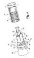
図1、図2を参照すると、本発明の、プライミングのために回転し、注射のために引いて/押す、機能を備えている、薬物投薬装置の第1実施例が示されている。一般に20で表示されている装置は、通常注射ペンとして知られている形で示されているが、他の形も発明の範囲内にある。薬物注射ペン20は使い捨てペンであり、その中に収容されている薬剤量がペンの複数回操作により使い尽くされると、ペン全体は、薬剤の取り替えコンテナーでリセットされかつ再び詰め込みされることなく、捨てられる。ペン20は、ユーザー内に固定服用量を供給するように繰り返し操作され、即ち、服用量は、ユーザーによりセット可能ではなく、ペンの特別設計のせいでペン製造者により指図された特定の量である。概念的には同様であるが設計が僅かに異なる注射ペンが、異なる固定服用量供給のために設けられ、そのような異なるペンの夫々は特別固定服用量の繰り返し投薬のためのみに適用される。 Referring to FIGS. 1 and 2, there is shown a first embodiment of a drug dispensing device according to the present invention that has the function of rotating for priming and pulling / pushing for injection. The device, generally designated 20, is shown in a form commonly known as an injection pen, although other forms are within the scope of the invention. The
注射ペン20は、先端針付きの先端部22と、基端部24と、を備えており、上記先端部は、ペン操作時に放出されるべき薬剤流体を収容しており、上記基端部24は、収容されている薬剤を針付き端部から押し出すのに使用される、注射およびプライミング機構を含んでいる。示されている実施例において、先端部22は、その中に保持された保持器28と、カートリッジ48と、を備えている。カートリッジ保持器28は、透明プラスチックで作られ、且つ、先端部30と基端部32とを備えている。保持器先端部30周りの外ねじ山34、または他の好適な連結手段が、一般的に38で表示されているペン−針アセンブリーを取り外し可能に接続するために使用されている。 The
ペン−針アセンブリー38は、周知の設計のものであり、且つ、一端に先端チップ42を、そして他端に図示されていない基端ポイントを、有する両頭針カニューラまたは注射針40を備えている。注射針40は、筒状ハブ44内に装着されており、このハブは、内側にねじ切りされて、図示の保持器設計と協働して、保持器先端部30のねじ山34上にねじ込まれ、外されるようになっている。針アセンブリーは、単一の注射針を有するものとして示されているが、本発明で使用される針アセンブリーは、当業者に知られている各種タイプであってもよく、限定するものではないが、マイクロ針アレーを含む1個またはそれより多い短縮された注射針付きアセンブリーを備え得る。 The pen-
カートリッジ保持器28の基端部32は、ガラスカートリッジ48を受け入れる開口を備えており、注射ペン20が製造業者により組み立てられるとき、このカートリッジを受け入れた後に保持器基端部32は、接着、超音波溶接または別の好適な方法によって、予めサブアセンブルされたペン基端部分24に対して固定的に装着または固着される。 The
カートリッジ48は従来設計のものであり、且つ、薬剤充満リザーバー50を区画している。該リザーバーは、その基端部でピストン52によって閉塞されている。該ピストンは、カートリッジ内壁と軸方向に摺動可能かつシール可能に係合して流体薬物をリザーバー50内に保持する。カートリッジリザーバー50の先端出口端部は、キャップ56によって保持されている隔壁54によって密封されており、該キャップは、カートリッジの縮径ネック部分49に固着されている。ペン−針アセンブリー38が、カートリッジ48を保持しているカートリッジ保持器28の先端部上に装着されると、注射針40の基端ポイントは、カートリッジ隔壁54を貫通して流体流出口を提供し、その出口によってカートリッジリザーバー50内の薬剤は、注射ペン20の操作中に針チップ42から投薬される。 The
図示され、上述された、流体薬剤コンテナーは、図解のためのものであり、且つ、限定されることは意図されていない。というのは、他の構造も本発明の範囲内で採用され得るからである。例えば、図示された流体コンテナーのように、別の保持器内に保持されている個別のカートリッジを持つのではなく、むしろ、流体コンテナーは、カートリッジ特徴部と一体化されている、ペンの外側ハウジングの伸長部の形で供給することができる。発明の別の流体コンテナーの実施例において、カートリッジは、充分な耐久性のものとして構成されており、且つ、周りに保護保持器を備えず、カートリッジに直接装着し得るペン−針アセンブリーを備えている、ペン基端部分24に、直接固着されるようになっている。 The fluid medicament container shown and described above is for illustration and is not intended to be limiting. This is because other structures may be employed within the scope of the present invention. For example, rather than having a separate cartridge that is held in a separate retainer, as in the illustrated fluid container, the fluid container is integrated with the cartridge features, and the outer housing of the pen Can be supplied in the form of an elongated portion. In another fluid container embodiment of the invention, the cartridge is configured to be sufficiently durable and has a pen-needle assembly that does not have a protective retainer around it and can be directly attached to the cartridge. The pen
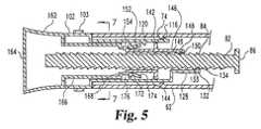
図3乃至図8において、注射ペン20のペン基端部24は、外側の、保護ハウジング60と、軸方向に前進可能な駆動部材80と、回転式駆動部100と、フォロアー140と、プランジャー160と、から成る。 3 to 8, the pen
ハウジング60は、ポリカーボネートのようなプラスチック材料から一部品として射出成形されており、且つ、先端部64および基端部66を備えている筒状ボデー62を有している。先端部64は、注射ペン20が製造業者により組み立てられるとき、カートリッジ保持器28に剛直に固着される。基端部66の近傍において、ボデー62の内面は、一連の軸方向に整列したラチェット歯68を備えており、これらの歯は、ハウジングボデーの基端部の全内側面周りに途切れることなく連続している。図7の断面内に最も良く示されているように、ラチェット歯68は、1個またはそれより多い爪108と係合するように一方向傾斜を持ち、この爪は、爪装着駆動部100のハウジング60に対して特別な方向への回転阻止に使用されている。ラチェット歯68の数は、この図示の実施例では36個であるが、好適な回転阻止能力を提供する、より少ないまたは多い歯、も使用され得る。 The
先端部64の近くに、ハウジングボデー62は、少なくとも1個、好ましくは1対のタブ70を備えており、このタブは、駆動部材80と係合してハウジング60に対するその回転を防止するのに使用されている。図8内に最も良く示されているように、タブ70は、ハウジングボデー内面の直径上反対側から半径方向内方へと突出しており、且つ、矩形ヘッド72を備えている。ヘッド72は、タブ70から基端側へと突出しており、且つ、更にボデー62側へ伸びてタブ70のための補強として機能する。タブヘッド72は、駆動部材80の溝90内に適合している。 Near the
回転阻止タブ70と、基端部66と、の間の軸方向位置のボデー内面上には、円周方向に伸びる肩部74が設けてあり、その肩部は、ラチェット歯68の頂点の高さの約2倍だけ半径方向内方へ突出している。肩部74は、駆動部100のためにラッチ点として機能する。肩部74は、ハウジングボデー内周周りに2区画を除いて連続しており、2区画では、そこを通してラチェット歯68が回転阻止タブ70側へと伸びている。これらの2区画は、図示のボデーの一部品成形を容易にするために設けられており、且つ、図示のハウジングが、適合半体が組み合わされるような、複数部品から形成されている実施例においては、肩部74のこれらの中断部は省略され得る。 A
駆動部材80は、駆動ねじの形であり、このねじは、ポリカーボネートのようなプラスチックから一部品として射出成形され得る。駆動ねじ80は、実質的にその全軸方向長さに沿う外ねじ山84付きのシャフト82を備えている。ねじ山84は、一条ねじであり、該ねじは、軸方向に対して直角で基端側へ向いた平坦面付きの軸方向断面で概ね直角三角形であり、かつそれはシャフト82に沿い旋回して螺旋形を創生している。多条ねじが、代わりに好適なねじの創生に使用され得る。 The
駆動ねじ80の先端部は、脚部86を備えており、該脚部は、シャフト82の横断面積より大きい面積を備えており、これによって、脚部86が接触し、且つ、ピストンが進められている間に直接係合する、カートリッジピストン52上の負荷を分散している。脚部86の周縁の2個の矩形ノッチ88は、ねじ80内に形成されており、直径上に配置されている、長手方向の、1対の溝90に、整列している。四角く切り取られた形状で、円滑な底面を有する溝90は、シャフト82の軸方向全長に伸びており、且つ、回転阻止タブヘッド72を摺動可能に受け入れ、駆動ねじ80のハウジング60に対する移行を許容している。脚部ノッチ88は、図4内に示されているサブアセンブリーに対し、一部品ハウジング60の製造業者による組み立て中に、溝90へのタブヘッド72の導入を許容する。図4は、フォロアー140とプランジャー160と駆動部100とから成っているサブアセンブリーへの組み立て中に、ねじ80がねじ込まれた結果、得られるサブアッセンブリーを示している。溝90の数は、好ましくは、それより少なく又は多くすることもできる回転阻止タブヘッド72の数、に対応しており、そのような溝およびタブの数は、好ましくは、示されているように2個に限定され、これによって耐久性のある、回転阻止構造を確保し、しかもねじ山に対して制限された妨害のみを創生するようになっている。 The distal end of the
プライミング駆動部100は、ABSのような弾力性プラスチック材料から射出成形されている。駆動部100は、筒状グリップ部分102を備えており、該グリップ部分102の先端部は、筒状ボデー部分104へと縮径されており、該ボデー部分104は、更にボデー部分107へと縮径されている。グリップ部分102は、ハウジングボデー62の外径と概ね適合する外径を有しており、それが隣接するハウジング基端部66内へと受け入れられている。グリップ部分102は、駆動部100の一部であり、この駆動部は、ペンプライミング工程のために、ユーザーによって手動で回されるため、外側から接近可能である。ペンプライミング中にユーザーの1またはそれより多くの指での接触による回転を容易化するため、グリップ部分102は、好ましくは高摩擦係数の弾性リング103が備えられており、このリングはグリップ部分の外周周りに摩擦適合またはできれば接着剤を介する等によって固着されている。図示されているリング103よりも、その上に一体に形成された半径方向突起のようなグリップ増強造作が、グリップ部分102内に成形さている。この場合において、駆動部100全体が、一部品構造品として形成され得る。 The
駆動部ボデー部分104は、グリップ部分102から先端側へ伸び、且つ、ハウジングボデー62の中空内部内へ挿入されるように寸法が定められている。ボデー部分104の基端領域内に、少なくとも1個の爪が形成されており、この爪はラチェット歯68と協働して駆動部100のハウジング60に対する回転を一方向に制限している。図示されている駆動部100において、略直径上で対向する1対の爪が、角度方向に伸び、半径方向に撓み得る指106の形態で設けられており、該指106は、ラチェット歯108に係合するのに十分なだけ半径方向外向きに伸びているキャッチ端部108を有している。図7内に示されているように、両爪が正確に直径上で対向しないように僅かにオフセットすることにより、ひとつのキャッチ端部108がラチェット歯68に係合し得る一方で、他のキャッチ端部108は、異なるラチェット歯68の中間部に接触することによって、内側に傾斜しており、これによってオフセット爪の角精度は、直径上に整列された場合の2倍になっている。図7から見ると、プライミング駆動部100は、ハウジング60に対して反時計方向に回転することができ、そのとき爪指106は、半径方向内側へ曲げられ、それからキャッチ端部108がラチェット歯68の傾斜面に沿って摺動して歯の頂点を越えると半径方向外方へスナップ移動する。プライミング駆動部100は、ラチェット歯68の半径方向整合の停止面と、爪キャッチ端部108のひとつと、の係合によって、ハウジング60に対する時計方向の回転を阻止されている。この回転の規制は、ペンプライミング達成のためにユーザーがプライミング駆動部100を適正方向に回すことを保証するだけでなく、駆動部の後述する駆動ねじとの連結により、不正確な服用量を来し得る駆動ねじの後退または基端側への動きを阻止するものである。 The
ボデー領域107は、更に、1対の隆起部分109を備えている。隆起部分109は、直径上で対向し、かつ、ラチェットリブ68に対してボデー領域107よりも、より近接しており、これによって駆動部100をハウジング60内で安定するようになっている。 The
駆動部ボデー部分107の先端部は、複数のスロット形ノッチ110によって、軸方向に突出した半径方向弾性的な指、の2セットへと分割されている。一般的に114と表示されている指の第1セットは、駆動部100をハウジング60へと組み立てると共に、フォロアー140を駆動部100へと組み立てるために使用され、且つ、それらは同じ形状とされている。指114は、注射ペン20内では3個であり、且つ、それらは120°離れて一点に中心が取られている。各指114は、ラッチリブ116と、停止リブ120と、を備えている。各ラッチリブ116は、その対応する指114の先端部近傍の外面から半径方向外方へと突出している。各停止リブ120は、リブ116の軸方向基端側位置で、対応する指114の内面から半径方向内方へと突出している。各リブ116の先端面は、傾斜またはカム面118を持ち、各リブ120の基端側面は、カム面122を持っている。 The distal end portion of the drive
ラッチリブ116は、ハウジング肩部74の先端側面と協働して、駆動部100をハウジング60内で軸方向に保持する。製造組立て中に、駆動部100を備えたサブアセンブリーが、図4内に示されているようにハウジング60内の先端側へと挿入されると、カム面118の全てと肩部74との係合が、指114の先端部を内側に曲げて、リブ116が肩部74上を通過することを許容し、そのとき指114はそれらの弾性構造により外方へ跳ね、これによってリブ116を肩部74にラッチして駆動部100の基端側への抜けを阻止する。リブ116は、軸方向位置が定められており、これによって、肩部74とのラッチ係合状態へと嵌め込まれたとき、ハウジング基端部66は、グリップ部分102の環状肩部105と密接な間隔を隔てた関係にあり、且つ、駆動部100のハウジング60内への更なる軸方向先端側への挿入は、肩部105のハウジングの端部との衝合によって阻止されている。 The
一般に126で表示されている指の第2セットは、L形伸長部128を備えており、且つ、駆動ねじ80に係合して駆動部の回転を駆動ねじの軸方向運動に変えるために使用される。3個の各指126の伸長部128のベース部は、連続した指114の間に配置され、かつ指126は120°を隔てて1点に中心が取られている。停止タブ136は、各指伸長部128の中央領域から横方向に突出している。 A second set of fingers, generally designated 126, has an L-shaped
突出したねじセグメント132は、各伸長部128の内面上に形成され、且つ、駆動ねじ80の外ねじ山84に噛合している。ねじ山84と完全に噛合するために、各ねじセグメント132は、対応する伸長部128上の異なる軸方向位置に配置されており、これによって、ねじセグメント132が、伸長部128の円周上または角度上の間隔から生ずる途切れが無ければ、ねじ機構80のねじ山84と同じピッチを備えている連続螺旋ねじを形成するようになっている。更に図5および6内に示されているように、各ねじセグメント132は、軸断面内で、傾斜基端側面133と半径方向に整列した停止面134とを備えている。駆動部100の弾性構造は、伸長部128の外方への拡開を許容し、これによって、後述するように駆動ねじが注射中に前進させられるとねじセグメント132が螺旋ねじ山84上を軸方向に摺動し得るようになっている。特に、ねじセグメント132は、傾斜ねじ面に沿って摺動し、且つ、それから、ねじ山84の一通路の軸方向端部とねじ山の隣接した通路の出発点との間の半径方向の断崖によって形成されている、凹部内へと差し込まれる。 The protruding
指114および126の各3個が示されているが、より少ないまたは追加の指も本発明の範囲内で使用され得る。例えば、伸長部128付きの1個のみの指も備えられるが、駆動螺旋ねじ山84との確実な直接的な係合を達成するためには、少なくとも2個が使用される。更に、ノッチ110から生じる、指114、および従って指126のベースが、駆動部を一部品ハウジング内にスナップ挿入すると共に、フォロアーを駆動部内にスナップ挿入するための可撓性を提供しているため、もしプライミング駆動部周りに組み立て得る複数部品ハウジングが使用され、かつフォロアーが組み立て中に内側に撓ませられる場合には、指114と、指126のベースと、は省略され、それらの特徴が連続スリーブ内に組み合わされ得る。 Although three of each of
駆動部100の内側中空部内で軸方向に可動なのは、一般的に140で表示されているフォロアーであり、該フォロアーは、アセタールのような弾性プラスチック材料から一部品として射出成形される。フォロアー140は、基端側面144付きの中央環142を備えており、該側面は、後述するように、ペンコッキング中に停止リブ120に衝合する。製造組立て中に、フォロアー140が駆動部100内に先端側へ挿入されると、環142がカム面122に係合し、指114を外側へ曲げて、環142のリブ120上の通過を許容し、その時点で指114が弾性的に内方へ跳ね返ってフォロアー140の基端側への引出しを阻止するようになっている。 A follower, generally designated 140, is axially movable within the inner hollow portion of the
注射ペン20内で示されている3個の指146のような、少なくとも1個の指、および好ましくは2個またはそれより多い指が、駆動ねじ80と係合するために環142の半径方向内側領域から先端側へと伸びている。3個の指146は、概ね矩形であり、且つ、120°離れて一点に中心が取られている。各指146は、先端部147と、半径方向内面に形成された内側へ突出したねじセグメント148と、を備えている。好ましい実施例においては、各ねじセグメント148は、駆動ねじ80の外ねじ山84に噛合し、かつそれらと好適に適合するために、各ねじセグメント148は、対応する指146上の異なる軸方向位置に配置されて、連続螺旋ねじの分割された部品として整列されている。図5、図6内に、更に示されているように、軸断面内の各ねじセグメント148は、傾斜基端側面149と、半径方向に整列された駆動面150と、を備えている。フォロアー140の弾性構造は、後述するペンコッキング中に、プランジャー160によってフォロアーが引かれるときに、指146の外側への拡開を許容し、これによって、ねじセグメント148が、回転しないように固定されているねじ機構80のねじ山84上を、軸方向に摺動することができる。 At least one finger, and preferably two or more fingers, such as the three
注射ペン20において、フォロアー140は、後述するように、注射中、その螺旋ねじ山との係合を使用して、駆動ねじ80を軸方向へと押す。フォロアーとねじとの間、および駆動部とねじとの間、の螺旋状ねじ整合性を維持するために、フォロアー140は、駆動部100に対してそれと共に回転するようにキー止めされている。このキー止めは、隣接した駆動部指伸長部128の間の間隙内に密接に適合している各フォロアー指146、によって達成されている。駆動部100とフォロアー140とは、異なる実施例では、代わりの方法によって互いに好適にキー止めされている。該代わりの方法は、環142内の追加ノッチ内に適合するスプライン、またはピンおよびスロットのようなものによって行う方法である。 In the
図示されていない別の実施例において、フォロアーは、注射中には駆動螺旋ねじ山に逆らって動くものではなく、むしろ、フォロアーは、ねじ山84から区別され、且つ、駆動ねじに沿って長手方向に伸びている、軸方向に間隔の開けられた歯の少なくとも1つのラック、に逆らって動くものである。この設計において、フォロアーは、駆動部100と共には回転せず、むしろ、駆動ねじに対して回転的に固定されている。この代わりの設計用のひとつの好適なラックは、1対のラックであって、ひとつが溝90の各々に形成されているものを用いるものであり、且つ、弾性フォロアー指が、2個の直径上で対向する指であって、該指が上記ラックと噛合するために、突出しているねじセグメント148、というよりもむしろ、横に突出している歯、を備えているものである。 In another embodiment not shown, the follower does not move against the drive helix thread during injection, but rather the follower is distinct from the
図示されている4個等の、複数個の装着用指152が、環154の半径方向内側領域から基端側へと伸びている。ラッチ154が、指152の基端部から半径方向外側へと突出している。 A plurality of mounting
プランジャー160は、ポリカーボネートのような軽量材料から射出成形されている。一部品構造を有するものとして図示されているが、製造容易化のために、プランジャー160は、筒状メインボデーの基端部上にキャップを付けたもののような、互いに組み合わされる複数部品で形成され得る。プランジャー160は、駆動部100の先端側へと伸びるグリップ部分162を備えている。該グリップ部分は、ペンコッキング目的のためにユーザーによって手動で引かれるように外側から利用しやすいものである。その基端方向への長さに沿い、グリップ部分162は、半径方向外方へ拡開しており、図1で左へ引くときに、ユーザーの親指と他の指の間でより確実に把持されるように構成されている。他の把持しやすいグリップ部分の構造は、置き換えることができる。該構造は、指が挿入されるループ、またはその下に指を巻き付け得るバーのようなものである。プランジャー160の基端部164は、押す面として機能し、その上に力が加えられてコックされたペンを図1の右へ押すことができる。
グリップ部分162の先端部は、筒状部分166へと縮径している。この部分166は、駆動部100の内側中空部内に適合し、且つ、ペン20の使用中に中空部の内外へと摺動することができる。内向きリップ168が、筒部分166の先端部に形成されており、且つ、4個の円周方向に間隔を隔ててあるバー170が、リップから軸方向へと突出すると共に、円錐台内面174を備えたプランジャーリング部分172を支持している。リング部分172と、リップ168と、の間の間隙は、プランジャー160の内周と、バー170と、の内側の間に、凹部または溝176を区画しており、該溝176は、注射ペン20において、プランジャー160をフォロアー140に軸方向相対固定、相対回転自在に連結するのに使用されている。 The tip of the
製造組立て中、フォロアー140がプランジャー160内基端側に挿入されると、内面174を通るラッチ154の係合が、ラッチ154が内面174を通過するまで、装着用指152の基端部を、内側へと曲げる。ラッチ154が内面174を通過したとき、指152は、それらの弾性構造のせいで外方へ跳ね、これによって、溝176内にラッチ154を入れ、且つ、プランジャー160が基端側へ動いたときに、フォロアー140の抜けを阻止するように、リング部分172の基端側面をラッチする。ラッチ154の基端面は、内側リップ168に衝合してフォロアー140のオーバー挿入を阻止するようになっており、且つ、プランジャー部材160の先端側への軸方向の動きがフォロアー140を軸方向先端側へ動かすようになっている。ラッチ154は、溝176内で摺動することができ、これによって、フォロアー140の回転が、プランジャー160の回転を、必ずしも起こすものではなく、逆もまた同じである、ようになっている。 During manufacturing assembly, when the
注射ペン20の構造は、図5、図6の事前参照と共に与えられる、以下のその操作説明によって、より良く理解されるであろう。まず、薬剤の服用を要するユーザーは、通常、図5内に示されているような準備完了状態のペン20を用意する。準備完了状態とは、ペンが以前の使用後の状態に留まっているか、またはペンがその最初の使用のためにユーザーに提供されている状態をいう。 The structure of the
ペン20は、最初にプライミングされる。典型的には、針チップ42を上に向けてハウジング60および/または先端部22を一方の手で掴んでいる間に、ユーザーは、彼女の他の手の1またはそれより多い指を使用して、リング103によって滑り阻止状態になっている駆動部グリップ部分102を掴み、該グリップ部分と、それによって駆動部100の残部全体と、をハウジング60に対して手動で回し始める。駆動部100は、ハウジング内で一方向のみに回転できる。これは、爪歯108のラチェット歯68との係合が反対方向の回転を阻止するからである。駆動部回転中の指伸長部128の回転は、駆動ねじ80を、先端側、または図5内で右に、軸方向に移行させる。これは、駆動ねじ80が、タブヘッド72によって、ハウジング60に対して回転が固定されているからである。特に、ねじセグメント132が、駆動ねじ80のねじ山84に係合しているので、ねじセグメント132が回されると、ねじ装置が回転しないように固定され、且つ、駆動部100が、ハウジング肩部74を備えているリブ116のラッチによって、ハウジング内で基端方向への軸方向の動きが阻止されているので、ねじ80は、先端側へと移行させられる。駆動ねじ80が先端側へと移行すると、図5、図6には示されていないカートリッジピストン52が、脚部86によって先端側へと押され、これによってカートリッジ内の薬物のためのリザーバー体積が減少し、薬物が針チップ42側へ押されるようになっている。通常、脚部86は、プライミングの開始時にはピストン52に接触しているが、ピストン52の動きが始まる前のプライミング駆動部の回転が、ペン20の最初の使用時に発生し易い、脚部86とピストン52との間の間隙を塞ぐ。駆動部100は、プライミング中、ユーザーによって連続的に回転することができる。この回転は、ほんの少しの僅かな回転、又は、1回又はそれより多い回数の回転、によらず、ユーザーが、ピストンの動きで薬剤が上向き針チップ42に達して全ての空気が排出されたことを見るまで行われる。全ての空気が排出されたとき、プライミングが完了するので、ユーザーは、駆動部100をねじることを止める。 The
ペンプライミング中、フォロアー140は、一緒にキー止めしてある駆動部100と共に回転するが、プランジャー160とフォロアー140との自由回転結合によって、プランジャー160は、同様に回る必要は無く、従ってプランジャーのねじりに対する任意の制限がプライミングを妨げることはない。 During pen priming, the
プライミングの後に、ペン20は、注射用に使用準備完了となる。引く工程は、設計された服用量投薬のために、未コックペン20をコックし又は準備するために、最初に実施される。この引く工程中であって、再びハウジング60および/または先端部分22が、一方の手で掴まれている間、ユーザーは、彼女の他方の手を利用してプランジャーグリップ部分162を駆動部100およびハウジング60から離れる軸方向に引く。プランジャーグリップ部分162は、固定された距離、特にフォロアー140の肩部144まで基端側へ引かれ、フォロアーもプランジャーとの連結により後方へ引かれ、停止リブ120に衝合する。この衝合は、プランジャー160の軸方向の動きを止める。このフォロアーの動作中、指146の先端部は、ねじセグメント148の傾斜基端面149がねじ山84の傾斜面上に滑り登ったときに、先ず、半径方向外方へ撓み、または湾曲し、それからねじセグメント148がねじの頂部を越えて滑ると内方へ跳ね返る。注射ペン20において、フォロアーが軸方向に動く距離は、ねじ山84のピッチより僅かに大きいだけであり、これによって、各ねじセグメント148は、ペンコッキング中に1度だけねじ山84を滑り越えるようになっている。駆動ねじ装置の軸断面に沿う、このねじ山84は、指ねじセグメントと係合するための、軸方向に間隔を隔てた一連の突起として作用する。代わりの実施例において、フォロアー140は、その収縮中に多数のねじ通路または突起を摺動して通過するようにされ得る。フォロアーねじセグメント148が、ねじ山84を越えて摺動すると、駆動ねじ80は、ねじ山84が駆動ねじセグメント132の停止面134と衝合することによって、基端側へ引かれることが阻止される。フォロアー環142が、駆動リブ120に衝突することから生ずる触覚信号の他に、プランジャー160の引きストロークの完了は、他の方法によっても表示され、その方法は米国特許出願第60/279070号“MEDICATION DISPENSING APPARATUS CONFIGURED FOR PULL TO SET DOSE AND PUSH TO INJECT SET DOSE FUNCTIONALITY”に開示されており、その全開示は参考資料として組み込まれている。 After priming, the
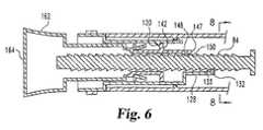
丁度この時点で、ペン20は、注射するように設計された服用量の薬剤を投薬するのにコックされ、または準備された状態となり、かつ図6内に示されている注射準備完了状態になる。もしユーザーが、予め辺20をプライミングしていないか、またはプライミングが既に行われていることを忘れていると、駆動ねじセグメント132が常に駆動ねじ山84に係合している事実に起因して、駆動部グリップ部分102は、コック状態からペンを動かすことなく、ペンのプライミングを起こすように、未だねじることができる。有利なことに、そのようなプライミングは、コックされたプランジャー160の次の押し込みによって放出されるべき薬剤量を変える恐れはない。 At this point, the
実際に薬剤を注射するために、注射針先端チップ42が、ユーザーの皮膚、または他の注射場所へ適正に貫通するようにペン20が操作された後に、軸方向の、先端側への押し込み力が、面164を押すために加えられて、プランジャー160を先端側へと加圧する。フォロアー140が、プランジャー160によって先端側へと動かされると、駆動ねじのねじ山84の、ねじセグメント148の駆動面150との衝合が、ピストン52をシフトし、且つ、薬物を、針40を通して押し出すように、駆動ねじ80を先端側へと移行させる。特に、ねじ山84のピッチは次のように選択されている。即ち、ピストン52をカートリッジ48内に前進させるのに必要な力が、ねじセグメント148とねじ山84との間の摩擦力克服に要する入力よりも小さく、かつ従って、ねじ80が、フォロアー140が回転される代わりに前進させられるように、選択されている。この駆動ねじ前進の間に、指伸長部128の先端部は、ねじセグメント132の傾斜面133が通過するねじ山84の傾斜先端面上へ滑り登るときに、半径方向外方へ撓みまたは曲り、それからねじ山の頂部が、ねじセグメント132を通過すると内方へ跳ね返る。プランジャー160の押し込み動作、およびそれによる駆動ねじ80の前進は、全てのフォロアー指146の先端部147が指伸長部128の停止タブ136に同時に衝突するときに、止められ、かつ薬剤注射は完了する。 In order to actually inject the drug, after the
ペン20は、カートリッジ内に残されている薬剤が好適な服用に不充分となるまで、固定服用量の放出に使用され続けることができる。この不充分は、例えば、駆動ねじ装置と協働する図示されていない停止部材と係合しているフォロアーに起因して、装置をコックするのにプランジャーを完全に引くことができない、ということによって示され得る。不充分な薬剤が残っているとき、ペン20は処分され、且つ、同様なしかし完全に新しいペンに取り替えられる。 The
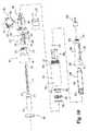
図9乃至図15において、そこには本発明によるプライミング用に回転し、注射用に引いて/押す形式の薬物投薬装置の別の実施例が示されている。一般的に220で表示されているこの装置は、カートリッジ内に収容されている薬剤量がペンの複数使用により使い尽くされた後、カートリッジは取り外されかつ充満したカートリッジと入れ替えられ、かつそのペンは再使用のために別方式でリセットされる、という点で、再使用注射ペンとして機能する。注射ペン20と同様に、ペン220は、使用毎にユーザー内に特別な固定服用量の放出に作用可能である。当業者により理解されるように、注射ペン220と、ペン20と、の設計は多くの面で同様であり、かつ従って注射ペン220の同様部分は詳述されないが、注射ペン20の或る部分は対応するように修正されている。 9-15, there is shown another embodiment of a drug dispensing device of the type rotating according to the present invention for priming and pulling / pushing for injection. This device, generally indicated at 220, is such that after the amount of drug contained in the cartridge has been used up by multiple uses of the pen, the cartridge is removed and replaced with a full cartridge, and the pen is It functions as a reusable injection pen in that it is reset differently for reuse. Similar to the
注射ペン220の先端部は、一部品保持器222と、内蔵されている薬物カートリッジ238と、を備えている。カートリッジ238は、カートリッジ48と同様であり、且つ、薬剤充満リザーバー240と、摺動可能ピストン242と、を備えている。カートリッジ保持器222は、不透明なプラスチックで作られているが、カートリッジ内蔵物を見ることができる、2個の窓223を備えている。保持器先端部226周りの外ねじ山225は、ペンニードルアセンブリー38と同様なペンニードルアセンブリー230の取外し式の接続に使用されており、アセンブリー230の注射針の基端点が、カートリッジ隔壁を貫通して流体出口を提供し、それによりカートリッジリザーバー240内の薬剤は、注射ペン使用中に投薬され得るようになっている。 The distal end of the
カートリッジ保持器222の基端部のカラー部分227は、カートリッジ238が着脱される中央開口を備えている。カラー部分227の外面上の一連の戻り止228は、図示されていないキャップの、キャップ内の噛合刻み目又は溝を介して行う、スナップ適合を許容している。カラー部分227は、保持器222を注射ペン220の基端部のハウジングに対して取外し可能に装着するための手段を備えている。そのような手段は、ハウジングアウターシェル250の外ねじ山257に接続する内ねじ山229として示されている。バヨネットタイプ接続または当業界で知られている他の接続システムのような、保持器の取り外し式装着の好適な形態が、本発明の範囲内で取り替えられ得る。 The
図9乃至図15の実施例内で示されている取外し装着可能な流体薬剤コンテナーの形態であって、処分可能なカートリッジと、再使用保持器と、を使用する形態は、単なる図解用であり、且つ、限定するものではない。流体コンテナーの他の形態であって、本発明の範囲内で採用され得るものには、使い捨て式保持器と、処分可能なカートリッジと、を備えている流体コンテナーであって、該保持器が、カートリッジに固定式に取り付けられて、共に処分可能とされており、且つ、該流体コンテナーが、新しいカートリッジ/保持器結合体として置き換えられるという、流体コンテナーを含んでいるが、これに限定されない。 The configuration of the removable drug container shown in the embodiment of FIGS. 9-15, using a disposable cartridge and a reusable holder, is for illustration only. And it is not limited. Another form of fluid container that can be employed within the scope of the present invention is a fluid container comprising a disposable retainer and a disposable cartridge, the retainer comprising: Including, but not limited to, a fluid container that is fixedly attached to a cartridge and made disposable together, and that the fluid container is replaced as a new cartridge / retainer combination.
注射ペン220の基端部は、複数部品ハウジングを備えており、このハウジングはアウターシェル250と、1対のインナーシェル半体251および252と、で形成されている。これらの各々は、ポリカーボネートのようなプラスチック材料から作られている。シェル半体251および252は、注射ペン220内で同一のものであり、従ってシェル半体251の更なる記述は、シェル半体252に対して等しく適用される。シェル半体251および252は適切に機能すれば同一である必要はない。 The proximal end of the
複数部品ハウジング構造は、以下のようにペンの製造を容易化する。即ち、製造中、インナーシェル半体251および252は、後述されるプライミング駆動部280周りに共に固定され、且つ、アウターシェル250内側でかつ該シェル250に対して、例えば、シェル半体の糊溝261に沿って適用された接着剤または他の好適なファスナーによって固着される、というようにペンの製造を容易化する。この固着は、シェル半体251、252がアウターシェル250内で軸方向に固定され、且つ、回転しないような固定をもたらす。シェル半体251および252は、駆動部周りに固着されたときに双方の角度端部で互いに接触するように設計されている。 The multi-part housing structure facilitates pen manufacturing as follows. That is, during manufacture, the inner shell halves 251 and 252 are fixed together around a
アウターシェル250は、基端部255と、先端部256と、を備えている筒状ボデー254を有しており、先端部256は、257で縮径され、且つ、外ねじ山が設けられており、カートリッジ保持器222を取り外し可能に装着するようになっている。先端部256の近傍において、ハウジングボデー254の内面は、1対の直径上で対向する半径方向内方へ突出したタブ259(図14参照)を備えており、これらのタブは駆動ねじに噛み合ってそのハウジング250に対する回転を阻止するようになっている。 The
シェル半体251および252の内面は、軸方向に整列した一連のラチェット歯263を備えている。組立て終了注射ペン220において、歯263は、ペンハウジングの全内周周りに途切れることなく連続している。ラチェット歯263は、一方向傾斜を有しており、ペンハウジングに対する爪装着駆動部280の特別な一方向への回転を阻止するように用いられる1またはそれより多い爪288によって係合されるようになっている。 The inner surfaces of the shell halves 251 and 252 include a series of axially aligned
注射ペン220内で軸方向前進可能な駆動部材は、駆動ねじである。該駆動ねじは、駆動ねじシャフト270と、ヘッド272と、を含んでおり、各々は、ポリカーボネートのようなプラスチックから射出成形されている。駆動ねじシャフト270は、基本的にその全軸長さに沿う外ねじ山274を有している。ねじ山274は、一条ねじである。該一条ねじは、一般に断面が直角三角形であり、その断面は軸方向に対して直交しかつ基端側に面した平坦面を持ち、かつシャフト270に沿ってねじれた螺旋パターンを創生している。シャフト270内に形成された1対の直径上に配置されかつ長手方向の溝276は、四角に仕切られて平坦な底部を有しており、且つ、シャフト270の実質的に軸方向全長に伸びて回転阻止タブ259を摺動可能に収容して駆動ねじのペンハウジングに対する移行を許容している。駆動ねじヘッド272は、駆動ねじシャフト270の先端でリップ状こぶ271上に従来方法でスナップ適合している。ねじヘッド272は、負荷をカートリッジピストン242上に分配する。駆動ねじシャフト270の基端部は、半径方向に突出したヘッド278を備えており、該ヘッドは更に後述するように不充分な残留物の服用停止部材として機能する。 The drive member that can advance in the axial direction within the
一般的に280で表示されているプライミング駆動部は、ABSのような弾性プラスチックから射出成形されている。駆動部280は、筒状グリップ部分282を備えており、該グリップ部分は、その先端部が筒状ボデー部分284へと縮径している。グリップ部分282は、ハウジングアウターシェル250の外径に概ね順応する外径を有しており、それに近接したハウジング端部255と融和するようになっている。弾性体またはO形リング285が、グリップ部分282の円周溝内に回転しないように緊密に適合している。Oリング285は、ユーザーの駆動部把持をより容易にし、かつ更に外観を改善する。グリップ部分282と、そのグリップリング285とは、駆動部280の一部であり、その部分は、ペンプライミングのためにユーザーにより手動で回されるべく外から接近可能である。 The priming drive, generally designated 280, is injection molded from an elastic plastic such as ABS. The
駆動部ボデー部分284は、グリップ部分282から先端側へ伸びており、且つ、インナーシェル半体251および252によって形成されている内側中空部内に入るようにサイズが定められている。1対の概ね直径上で対向する爪が、角度方向に伸び、半径方向に撓み得る爪指288の形で設けられている。爪指は、キャッチ端部289を備えており、ラチェット歯263と係合するように半径方向外方へ充分伸びてシェル半体251、252に対して駆動部280の回転を単一方向に制限している。特に、プライミング駆動部280は、ペンハウジングに対して第1方向に回転され、それは爪指288が半径方向内方へ曲げられ、かつそれからキャッチ端部289が、ラチェット歯263の傾斜面に沿って摺動し、それから歯の頂部を越えて落ちると、半径方向外方へと跳ねる。プライミング駆動部280は、ひとつの爪キャッチ端部289のラチェット歯263の半径方向整列停止面との係合によって、注射ペン220のペンハウジングに対する第1方向と反対方向への回転が阻止されている。 The drive body portion 284 extends from the
駆動部ボデー部分284の先端領域は、複数のスロット形ノッチによって2セットの軸方向に突出した半径方向に撓み得る指に分割されている。一般的に293と表示されている指の第1セットは、駆動部280に対するフォロアー320との関係と同様に、駆動部280をペンハウジングに組み込むのと同じ形状が定められかつ使用されている。指293の数は、2個であり、且つ、180°隔てて一点に中心が取られている。各指293は、装着リブ296と、停止リブ298と、を備えている。各装着リブ296は、その対応する指294の外面の先端部近傍から半径方向外方へと突出している。各停止リブ298は、その対応する指294の内面のリブ296の軸方向基端位置から半径方向内方へと突出している。 The tip region of the drive body portion 284 is divided into two sets of radially deflectable fingers projecting axially by a plurality of slot-shaped notches. The first set of fingers, generally labeled 293, is defined and used in the same shape as incorporating the
装着リブ296は、駆動部280周りに配置されたシェル半体251、252の溝265内に適合し、摺動する。シェル半体251、252が、ハウジング250内に固着されると、溝265内でのリブ296の相互適合が、駆動部280がハウジング250内で軸方向に相対的に固定されるが回転できる、という結果を生じる。 The mounting
一般的に300で表示されている指の第2セットは、駆動部の回転を駆動ねじの回転運動に変えるために、駆動ねじシャフト270に係合するのに使用される。注射ペン220において、各指300は、ベース302と、縮径部304と、カム部分306と、チップ部分308と、を備えている。2個の指300の夫々のベース302は、連続した指293の間に位置しており、かつ指300は180°離れて一点に中心がとられている。突出したねじセグメント310は、各チップ部分308の半径方向内面上に形成され、且つ、駆動ねじシャフト270の外ねじ山274と噛合している。各ねじセグメント310は、その対応するチップ部分308上の異なる軸方向位置に配置されており、これによって、ねじセグメント310が、チップ部分308の円周上の間隙に起因して生ずる中断部分が無ければ、螺旋ねじ山274と同じピッチ付きの連続螺旋ねじの部分を形成する。軸方向断面における各ねじセグメント310は、傾斜した基端側面と、半径方向に整列した停止面と、を備えている。駆動部280の弾性構造は、指300の外側への拡開を許容し、注射中に駆動ねじが前進する時、ねじセグメント310がねじ山274を越えて軸方向に摺動し得るようになっている。 A second set of fingers, generally designated 300, is used to engage the
駆動部280の内側中空部内で軸方向に可動なのは、一般的に320で表示されているフォロアーであり、該フォロアーは、アセタールのような弾性プラスチックから一部品として射出成形されている。フォロアー320は、筒状ベース322を備えており、該ベースは、その基端部に形成された180°隔たった2個のスロット324を備えている。ペン使用中、プランジャーの運動量を制限する1対の停止リブ328および330が、ベース322から半径方向に突出している。停止リブ328は、環であり、ベース322を完全に繋いでおり、且つ、停止リブ330は、スロット324における中断を除いて連続している。製造組立て中、フォロアー320が、駆動部280内に先端側へ挿入されると、停止リブ328の先端側傾斜面部分329が、駆動部停止リブ298に係合して指293を外側へ曲げ、これによって、停止リブ328が駆動部停止リブ298上を通過することを許容し、その時点で指293が、内方へ弾性的に跳ね返りフォロアー320の基端側への抜けを阻止するようになっている。 The axially movable follower in the inner hollow portion of the
ベース322の先端部の環状フランジ333は、中央開口334を区画している。1対の直径上に対向する停止部材336が、該開口334へと半径方向に突出している。中央開口334内での複数の停止部材336の間の間隙は、駆動ねじシャフト270を収容するには充分大きいが、ねじシャフト270の基端部で停止ヘッド278の通過を許容するには充分な大きさではない。停止部材336のシャフトヘッド278による衝突が、注射ペン220の不充分な残留服用量インジケーターとして機能する。 An
フランジ333から軸方向に突出しているものは、一般的に338で表示されている1対の指であり、これらの指は180°離れて一点に中心がとられている。各指338は、起立したベース部分340と、カム部分342と、チップ部分344と、を備えている。各チップ部分344は、半径方向内面上に形成された内側へ突出したねじセグメント346を備えており、このねじセグメントは、駆動ねじシャフト270の外ねじ山274と噛合している。各ねじセグメント346は、その対応チップ部分344上の異なる軸方向位置に配置されており、連続した螺旋ねじの分離した部品として整列されている。軸断面内の各ねじセグメント346は、基端側の傾斜面および半径方向に整列した駆動面を有しており、かつフォロアー320の弾性構造は、後述するように、ペンコッキング中、フォロアーがプランジャー360により基端側へ引かれたときに、指338の外方への拡開を許容し、そのときねじセグメント346が回転しないように固定されている駆動ねじシャフト270のねじ山274を越えて軸方向に摺動するようになっている。 Protruding axially from the
フォロアー320は、螺旋ねじ山274との係合を使用して注射中に駆動ねじシャフト270を軸方向に押す。フォロアー320は、駆動部280に対してそれと共に回転するようにキー止めされている。注射ペン220において、このキー止めは、各フォロアー指チップ部分344が隣接駆動部指チップ部分308の間の間隙内に密接に適合することによって達成される。特に、チップ部分344は、チップ部分308との関連により寸法決めされており、これによって、ペン注射器が、図13内に示されている安定状態にあるときに、チップ部分344および308の傾斜端面が接触するようになっている。この接触は、安定状態ある間、可撓性指のいかなるねじれをも阻止することを助ける。 The
駆動指300の、縮径部304とカム部分306と、の角度寸法と同様に、フォロアー指338の、ベース部分340とカム部分342と、の角度寸法は、隣接指300および338の間に、後述するウェッジの連結アームを収容するスロットを区画するように選択されている。 Similar to the angular dimension of the reduced
フォロアーベース322のスロット324は、プランジャー360へ向かい基端側へと伸びる1対の装着指325、として機能するベース322の基端領域を、結果として生じる。ラッチリブ350が、各装着指325の基端部から半径方向外方へと突出している。 The slot 324 in the follower base 322 results in a proximal region of the base 322 that functions as a pair of mounting
一般的に360で表示されているプランジャーは、ポリカーボネートのような軽量材料から2部品として射出成形されている。プランジャーは、筒状メインボデー361と、キャップ362と、を備えており、該キャップは、メインボデーの基端部上に摩擦適合している。プランジャーメインボデー361は、駆動部280の先端側へ伸びるグリップ部分364を備えており、該グリップ部分は、ペンコッキング目的のためにユーザーによって手動で引かれるように外側から利用することができる。基端方向への長さに沿って、グリップ部分364は、半径方向外方へ拡開しており、図9で左方へ引かれるときに、親指と他の指との間などでユーザーによって、より容易に掴み得るようになっている。他の掴み得るグリップ部分構造は、取り替えられ得る。キャップ362によって形成されているプランジャー360の基端部は、コックされているペンのプランジャーを、図9で右方に押す力が印加される、押す面として機能する。 The plunger, generally designated 360, is injection molded as a two-part from a lightweight material such as polycarbonate. The plunger includes a cylindrical
グリップ部分364の先端部は、筒状部366および368へと縮径している。これらの筒状部は、駆動部280の内側中空部に適合し、且つ、ペン使用中、そのような中空部に摺動して入出可能である。内側リップ370が、筒状部分368の先端部に形成されており、かつ4個の円周方向に間隔を隔てたバー372が、該リップから軸方向に突出しかつ途中で止まっている、頭部の切り取られたような円錐形の内面376を備えたプランジャーリング部分374を支持している。リング部分374と、リップ370と、の間の間隙は、プランジャー360の内周と、バー372の内側周りと、に凹部または溝378を区画しており、該溝378が、プランジャー360のフォロアー320との連結に使用されており、軸方向に固定されるが回転自在に動くことができるものとなっている。 The tip of the
製造組立て中、フォロアー320が、プランジャー360内に基端側へと挿入されると、ラッチリブ350の内面376による係合が、ラッチリブ350が内面376を通過するまで、装着指325を内側に曲げ、該通過時点で、指325が、それらの弾性構造のせいで外側へ跳ね、これによって、ラッチリブ350を溝378内に入れ、且つ、リング部分374の基端面をラッチして、プランジャー360が基端側へと動く時に、フォロアー320の先端側への抜けを阻止するようになっている。ラッチリブ350の基端面は、内側リップ370に衝合して、フォロアー320の過剰な挿入を阻止すると共に、プランジャー部材360の先端側への軸方向の動きを起こし、これによって、フォロアー320を先端側へ軸方向に動かすようになっている。 During manufacturing assembly, when the
プランジャー360内に伸びているものは、プラスチック製安定化スリーブ353である。スリーブ353は、ねじシャフト270の半径方向の偏向を阻止するのを助けるために備えられている。スリーブ353は、キャップ362内に形成されたカラー380内に圧入するように示されているが、代わりにフォロアー320に対して装着され得る。 Extending into the
注射ペン220において、使い尽くされたカートリッジの取り替えを行うとき、駆動ねじのリセットに使用される機構は、ウェッジまたはカム要素385と、付勢部材387と、インターフェース要素389と、を備えている。これらの物は、全てペンハウジング250内に収容されている。この機構は、カートリッジが取り外されると、ユーザーによってその上に手動操作を加えることなく自動的に、駆動ねじシャフトと、フォロアーと駆動部との双方と、の間に存在していた螺合を解除して、駆動ねじが基端側へシフトされることを許容する。 The mechanism used to reset the drive screw when replacing a depleted cartridge in the
ウェッジ385は、中央孔393付きの円形カムリング391を備えており、その中央孔を通して駆動ねじシャフト270が、伸びている。カムリング391は、駆動ねじシャフト270と、駆動部指300とフォロアー指338との双方と、の間の間隙内に適合している。カムリング391は、駆動部縮径部304またはフォロアーベース部分340に接触することなく軸方向に摺動するのに充分に小さいサイズに定められている。カムリング391は、ウェッジ385が図13内に示されている位置から先端側へと摺動されるときに、駆動部カム部分306と、フォロアーカム部分342と、の内側円錐面に直接係合するのに充分な大きさに定められており、該係合は、チップ部分308および344の半径方向外側へカム係合しており、これによって、ねじセグメント310および346が、駆動ねじ山274から外れ得るようになっている。 The
ウェッジ385は、4個のL形連結アーム395を有している。該アームは、カムリング391と、大きい直径の、より先端側に配置された、円形アウターリング397と、をつないでいる。ウェッジ385の軸方向運動中、各連結アーム395は、隣接した駆動部縮径部304と、フォロアーベース部分340と、の間に形成されているスロット内で摺動する。アウターリング397は、駆動部指300と、フォロアー指338と、を囲みかつそれらと間隔を隔てた関係にある。リング397の外縁は、ペンハウジングシェル250と密接な間隔を隔てた位置にあり、ハウジングとの同心性を促進するようになっている。 The
付勢部材387は、ウェッジ385を軸方向のある位置へと押す機能を果たす。上記ある位置で、ウェッジは、フォロアーと、駆動部指と、を外側へカム動作させて、駆動ねじを脱係合する。付勢部材387は、コイル状金属圧縮ばねとして示されており、該ばねは、連結アーム395の半径方向外側のアウターリング397の下側に衝合する第1端部と、シェルインナー半体251、252の端面上に着座しているアセタールワッシャー399に衝合する他端と、を備えている。付勢部材および構造材料の他の知られているタイプが、この金属圧縮ばねの代わりに取り替えられ得る。ワッシャー399は、ばね387をウェッジ385と共によく回転させることができる。該ウェッジは、駆動部280とフォロアー320とを、その間に連結アーム395を捕獲することに起因して、共に回転させる。 The biasing
インターフェース要素389は、ウェッジ385を、実装された流体コンテナーと、特に図示されている注射ペン220の構造内ではカートリッジ238と、に作動可能に連結している。インターフェース要素389は、1対の脚部402が吊り下がっているカラー部分400を備えている。各脚部は、横断面内で外側または弓形に湾曲しており、且つ、半径方向に突出した衝合リブ404と、軸方向に突出した整列リブ406と、をその基端部に備えている。注射ペン220が組み立てられるとき、リブ406は、ウェッジアウターリング397の中央孔内に適合して、要素389とウェッジ385との同心配置を助けるようになっており、且つ、衝合リブ404は、アウターリング397の先端面に接触して、インターフェース要素389上に基端側へと向かって加えられる力を、ウェッジ385に伝えるようになっている。各脚部402の両側で長手方向に伸びているリブ408は、脚部の強度を増す。 The
カラー部分400は、半径方向に突出した環状フランジ410を備えている。該フランジは、アウターハウジング250の内側体積内でインターフェース要素389を中心に置き、同時にハウジングとインターフェース要素との間の半径方向間隙を非常に小さくする。カラー部分400の先端面は、縮径されており、且つ、面取りをした面412と、カートリッジ衝合面414と、を備えている。面取りをした面412は、注射ペン220が使用のために組み立てられたとき、カートリッジ238の基端部の面414上への位置決めを助ける。インターフェース要素389は、カートリッジが存在しないときに、ハウジングの一部のような、ペンの他の部分と係合することによって、ハウジング250の外に落ちることが阻止されている。例えば、インターフェース要素は、1またはそれより多い図示されていない一方向スナップを備えている。該スナップは、製造挿入中、回転阻止タブ259の上に適合し、かつ下側を軸方向に固着する。該スナップは、タブ259の下側と衝合していることに起因して、基端側への挿入は阻止しないが、インターフェース要素389のペンハウジング250からの先端側への抜けを阻止している。 The
注射ペン220の構造は、主に図13乃至図15に関連した以下の動作説明からより良く理解されるであろう。まず、薬物の投薬を要するユーザーは、注射ペン220を図13内に示されている準備完了状態にする。 The structure of the
ペン220は、まず注射ペン20に関連して記述したのと同様な方法でプライミングされる。プライミングの後、ペン220は、依然として図13内に示されているように準備されており、注射使用のために準備完了状態にある。グリップ部分364を掴むことによって、ユーザーは、プランジャー360を駆動部280から離れるように軸方向に引いて、意図された服用量の投薬のために注射ペンをコックする。プランジャー360の基端側への動きは、フォロアー停止リブ328の下側が駆動部280の停止リブ298に衝合したとき、停止される。上記フォロアーも、プランジャーとの連結に起因して基端側へと引かれる。このプランジャー/フォロアーの基端側への動作中、フォロアー指338の先の部分は、外方へ撓みかつ外ねじ山274の上を摺動する。プランジャー/フォロアーの基端側への動作中、ねじ山274の駆動部指300のねじ310の係合が、駆動ねじシャフト270が基端側へ引かれることを阻止する。この時点において、ペン220は、注射するべく設計された服用量を投薬するようにコックまたは準備され、かつ図14内に示されている注射準備完了状態に準備される。
実際に薬剤を注射するには、ペン220が、注射針が適当にユーザーの皮膚を貫通するように、操作された後、軸方向の先端側への押し込み力が、プランジャー360と、および従ってフォロアー320と、を押すためにキャップ362に加えられる。フォロアー320が、プランジャー360によって先端側へと動かされると、駆動ねじ山274のねじセグメント346による衝突が、駆動ねじシャフト270の先端側への移行を起して、カートリッジピストン242をシフトさせ、且つ、薬物をペン針を通して押し出す。この駆動ねじの前進の間に、駆動部チップ部分308は、外側へ撓み、かつねじ山274上を摺動し通過する。プランジャー360の押し込み動作と、それによる駆動ねじシャフト270の前進とは、フォロアー停止リブ330の先端面が駆動部停止リブ298の下側に直接衝合したとき、停止され、薬剤の注射が完了する。 To actually inject a drug, after the
ペン220は、カートリッジ内に残留している薬剤が好適な服用に不足になるまで、上述の方法で固定服用量投薬のために使用継続され得る。この不足は、彼または彼女が注射ペン220を充分にコックするためにプランジャーを引き出すことが不可能になるということによって、ユーザーに示される。特に、プランジャー360が基端側へ引かれると、フォロアー停止部材336が、駆動ねじシャフト270のヘッド278に直接衝合する。該衝合は、フォロアーねじセグメント346がねじ上を完全に通過することを阻止し、これによって、プランジャー引き出し力が取り除かれたとき、プランジャー360は、典型的には、フォロアー指の弾性復帰によって、ペンハウジング内の図13内に示されている準備完了状態へと引き戻される。 The
不充分な服用量しか残されていないときにのみ、ユーザーは、カートリッジ238を交換しかつペン220をリセットすることができる。特に、カートリッジ保持器222が脱螺合されると、カートリッジと、カートリッジ保持器と、がアウターシェル250から取り外され、かつカートリッジが保持器から除去されかつ捨てられるようになっている。カートリッジ238が、そのように取り外されたとき、コイルばね387が、ウェッジ385と、インターフェース要素389と、を先端側へと押す。ウェッジ385が先端側へ動くと、それが駆動部とフォロアーとのカム部分306および342に遭遇してチップ部分308および344を外側へ拡開する。チップ部分が、そのように拡開すると、それらの対応するねじセグメントは、もはや駆動ねじシャフト270のねじ山274と係合せず、且つ、駆動ねじが基端側へと、ヘッド278の基端面が図示されていない底部停止部材と衝合するまでシフトされることができる。該底部停止部材は、プランジャーキャップ362の内面上に備えられた中空筒状突起のようなものである。 Only when insufficient dose is left can the user replace the
駆動ねじを基端側へシフトさせるため、ユーザーは、それから、例えば、伸長した駆動ねじ270を、注射ペン220の基端部内に彼女の指で手動で押し戻す。しかしながら、インターフェース要素389のカラー部分400内の中央孔が、平均的な指よりも小さいので、ユーザーの指は、結果的にインターフェース要素389をねじ270に沿って押し下げ始めることになる。そして、インターフェース要素およびそれによってカム要素385が少量だけ押し下げられると、駆動部とフォロアーと、の可撓性指の外側へのカム動作は終り、且つ、ねじセグメントが再び駆動ねじ山274に係合する。該再係合が、駆動ねじ270のそのヘッド278の底部停止部材に対する完全なリセットを阻止し得る。従って、完全なリセットを確保するには、ユーザーは、鉛筆、あるいは、ペン220に備えられている専用工具、のような工具の使用に頼らなければならない。該工具は、駆動ねじを押し戻すのに使用されるときに、かろうじて通過するが、インターフェース要素を動かさないものである。 To shift the drive screw proximally, the user then manually pushes back, for example, the
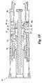
別の外部工具の使用を要することなく、駆動ねじの完全なリセットを確保するため、ペン注射器の駆動ねじリセット機構は、駆動ねじを基端側へ付勢するための追加のばね器具を採用することができる。ひとつのそのような器具は、図18、図19内に抽象的に示されており、且つ、後述する修正を除いて、注射ペン220と同様な注射ペン500内で使用されている。該器具は、一般的に502で表示されている少なくとも1個、好ましくは2個、のオーバーセンターばね負荷アセンブリーを採用している。該アッセンブリーは、駆動ねじ内に備えられている凹部と共に動作する。各アセンブリー502は、図示されている枢動可能部材504と、図示されていない付勢部材と、を備えている。該付勢部材は、枢動可能部材504を図19内に示されている配置へと押しやすくする。ねじりばねまたはリーフばねのような、ばねの知られたタイプであり得る付勢部材は、部材504およびペンハウジングの間で作用する。枢動可能部材504は、フォーク部分505と、指部分506と、を有しており、上記フォーク部分505は、フォーク部分505の両側上のシェル250内に形成されている図示されていない2個の突出耳に対して枢動可能に装着されており、上記指部分506は、フォーク部分505から突出しかつ駆動ねじ270の溝276内に適合している。指部分506のチップは、ねじ内の凹部によって形成された隆起507に対して動作するように寸法が定められている。該隆起は、図示の実施例において、溝276をつないでいる貫通孔508によって形成されている。注射ペン500の使用中、指部分506のチップは、溝276に沿って摺動する。カートリッジが取り替えのために取り外され、かつフォロアーと駆動部可撓性指とが自動的に外側へ拡開し、かつ駆動ねじがペン500に対して新しいカートリッジ実装の準備のためのリセット−このリセット工程は図18内に示されている−中に手動で押し戻され始めたとき、オーバーセンターばね負荷アセンブリー502は、リセットに干渉も補助もしない。しかしながら、駆動ねじリセットが、ある点、ただしインターフェース要素が下方へ押される前の点、に達したとき、例えば、駆動ねじが、その意図された行程の底部から約6mmあるとき等、指部分506の指のチップが、孔508内に入ると共に、ねじ隆起507に近接作動し、且つ、図示されていない付勢部材が、枢支部材504を図19内に示されている位置へと自動的に跳ね下ろしてユーザーのために駆動ねじの下降を終了し、駆動ねじ270が、底部停止部材に対してそのヘッドによって完全にリセットするようになっている。オーバーセンターばね負荷アセンブリー502は、これによって駆動ねじが、その底部位置へと達したことを確保するだけでなく、駆動ねじが好適にリセットされたことを積極的にフィードバックする。 In order to ensure a complete reset of the drive screw without requiring the use of a separate external tool, the drive screw reset mechanism of the pen syringe employs an additional spring device for biasing the drive screw proximally. be able to. One such instrument is shown abstractly in FIGS. 18 and 19 and is used in an
他の実施例においては、駆動ねじの完全なリセットを確実にするため、異なる要素が採用され得る。そのような要素は、プランジャーキャップと、駆動ねじ基端部と、の間に装着されている一定力ばね、またはプランジャーキャップの内側に装着されたクリップばねであって、ねじリセット中に駆動ねじヘッド278がその中に挿入されたとき、駆動ねじを掴みかつ基端側へ引くように形作られているもの、を備えている。 In other embodiments, different elements may be employed to ensure complete reset of the drive screw. Such an element is a constant force spring mounted between the plunger cap and the drive screw proximal end, or a clip spring mounted inside the plunger cap, which is driven during screw reset. The
駆動ねじのリセットの後、注射ペン220の基端部は、図15に示されているように準備される。 After resetting the drive screw, the proximal end of the
新しい取り替えカートリッジ238が、カートリッジ保持器222内に挿入された後、ペンハウジングに対するカートリッジアセンブリーの再装着は、カートリッジがインターフェース要素389に衝突してそれを基端側へと押し、このことは、次にウェッジ385をばね387によって提供されている戻し力に抗して基端側へと押す、という結果を生じる。評価されるべきことは、もしペン220が図18および19内に示されているようなリセット補助器具を備えているなら、この再装着は、ユーザーの指によって押し戻されている駆動ねじの代わりに、駆動ねじをリセットするのに使用することができる。というのは、ペン220の再組み立て中、保持器222内に取り付けられた新しいカートリッジがシェル250に対して取り外し可能に装着されているとき、駆動ねじが、カートリッジピストンとの接触によって押し戻され得るからである。 After the
ウェッジ385が基端側へと動くと、駆動部とフォロアーと、の可撓性指の外側へのカム動作が終り、且つ、ねじセグメントは、駆動ねじ山274と再係合する。カートリッジアセンブリー再装着の後、注射ペン220は、別の新しいカートリッジが所望されて工程が繰り返される時まで、前述の方法でプライミングされ、使用される。 As the
当業者によって評価されるべきことは、注射ペン220は、取り外し可能に装着されるのと反対に、単にペンハウジングに対してカートリッジを実装したカートリッジ保持器を固着式に装着するだけの使い捨てペンとして製造され得る。そのような使い捨て実施例においては、駆動ねじのリセットが不必要であるためインターフェース要素389と、ウェッジ385と、ばね387と、が省略され得る。 It should be appreciated by those skilled in the art that the
駆動ねじをリセットするため、注射ペン220に用いられている図示した機構が、好ましいものではあるが、駆動ねじをリセットするための他の機構は、本発明の代わりの再使用可能な装置に取り換えることができる。例えば、図16内に概略図示されているように、注射ペン430は、ウェッジ385と、付勢部材387と、インターフェース要素389と、を欠いている他、注射ペン220と同じ作動要素を備えている。その代わりに、注射ペン430のリセット機構は、内側部分を備えている極めて接近容易な摺動可能カラーを備えている。該内側部分は、駆動部とフォロアーとの指を係合している駆動ねじに追加されたカムアームと係合している。該カラーは、環状グリップ部分432と、環状フランジ434と、円周上に間隔を隔てて設けられているブリッジ436と、を備えた一部品で形成されており、上記環状グリップ部分432は、ペンハウジング周りに配置されており、上記環状フランジ434は、ペンハウジング内側体積内に存在しており、上記ブリッジ436は、グリップ部分432とフランジ434との橋渡しを行い、ペンハウジングを通るスロット内を摺動する。環状フランジ434の基端面435は、ウェッジ形である。ユーザーが駆動ねじ437のリセットを希望し、かつカートリッジアッセンブリが、伸長駆動ねじに接近するために取り除かれた後、グリップ部分432がグリップされ、且つ、カラーが、注射ペンに対して図16の状態から手動で基端側へ、または下方へと押され得る。カラーがそのように基端側へ押されると、ウェッジ面435がL形カムアームに係合し、かつ外側へと押す。該カムアームは、フォロアー指438から突出している図示のカムアーム440のように、駆動部とフォロアーとの全ての可撓性指と一体に形成されかつ可撓性指から半径方向外方に突出している。カムアームの外側への加圧は、それらの対応する可撓性指を半径方向外方へ拡開して、可撓性指のねじセグメントを駆動ねじ437から脱係合させ、これによって駆動ねじが、カートリッジ装着中に基端側へと、落ち、または、手動で押し戻され又は強制的に押し戻される、ことを許容している。カラーグリップ部分432上への基端側への力が解放されると、駆動部とフォロアーと、の可撓性指の弾性が、指を駆動ねじ437との螺合位置へと復帰させる。該復帰は、カラーを図16内に示されている準備完了位置へと上向きに加圧する。カラーを上向きに付勢する追加の付勢要素が、別の実施例において使用され得る。 While the illustrated mechanism used in
駆動部とフォロアーと、の指を外側に拡開することによって機能する、別の駆動ねじリセット機構において、ハウジング周りに配置された外側グリップ部分を有している手動回転可能カラーが、備えられている。ペンハウジング内において、カラーは、軸方向にぶら下がっているカム突起物を備えている。該突起物は、例えば、駆動部とフォロアーと、の可撓性指の先端面上に備えられているトラック内で動く。該トラックは、突起物によるカム動作のために構成されており、これによって、カラーがユーザーにより中立角度位置からカム角度位置へと第1方向に手動でねじると駆動部とフォロアーとの可撓性指が半径方向外方へ押されて可撓性指のねじセグメントを駆動ねじから脱係合し、駆動ねじはそれから押し戻され得る。ユーザーが、カラーを解放すると、可撓性指は、それらの可撓性構造に起因して、駆動ねじと係合しているそれらの準備完了位置へと跳ね返り、これによって、カラーを、そのカム位置からその中立位置へと戻るように、ねじる。 In another drive screw reset mechanism, which functions by spreading the drive and follower fingers outward, a manually rotatable collar having an outer grip portion disposed around the housing is provided. Yes. Within the pen housing, the collar includes a cam projection hanging in the axial direction. The protrusion moves, for example, in a track provided on the distal end surface of the flexible finger of the drive unit and the follower. The track is configured for cam action by protrusions, so that the flexibility of the drive and follower when the collar is manually twisted in a first direction from the neutral angle position to the cam angle position by the user. The finger can be pushed radially outward to disengage the flexible finger's screw segment from the drive screw, which can then be pushed back. When the user releases the collar, the flexible fingers bounce back to their ready position engaged with the drive screw due to their flexible structure, thereby causing the collar to move to its cam. Twist back from position to its neutral position.
駆動部とフォロアーとの可撓性指を、駆動ねじから脱係合させることによって機能する、例えば、図9乃至図15、図16の実施例の駆動ねじリセット機構に加えて、駆動ねじをリセットするための本発明の範囲内の他の機構は、好ましくは、薬物カートリッジが装着されていないときにのみ、可撓性指が逆回転することを許可することによって機能し、これによって、駆動ねじをハウジング内へと基本的に引き戻すようになっている。例えば、そのような逆回転を許容している注射ペンの部分は、図17内に概略的に示されている。図17の注射ペン450は、殆どの点でペン220と同じであるが、そのフォロアーおよび駆動ねじを含むが限定されない、ペン450の主要部分は、駆動ねじリセット機構をより明確に図示するためには示されていない。ペン450のプライミング駆動部は、弾性爪454を備えており、この爪は、駆動部可撓性指の縮径部452のベースレッグの先端面上に形成されている。環状クラッチ456は、ペンアウターシェル458内で軸方向に可動であり、且つ、その中での回転が、半径方向に突出したキー460によって阻止されている。該キー460は、シェル内の長手方向のキー溝または凹部462内で摺動する。爪454と噛合する一方向クラッチ歯464の環状配列が、クラッチ456の基端面上に配置されている。クラッチ456は、コイルばね466によって図17の先端側または中立位置へと付勢されるものとして示されている。駆動部縮径部452に対して直接作動するように示されているが、ばね466は、アウターシェルの図示されていない内側へ突出した肩部上に着座され得る。カートリッジ保持器470がペンハウジング458内にねじとめすることによって装着されているとき、カートリッジ保持器、または好ましくはその中に実装された図示されていないカートリッジが、クラッチ456に衝合し、且つ、それを図17から下方へ圧縮ばね466に抗して押す。カートリッジと、保持器470と、が完全に装着されると、爪454がクラッチ歯464と整合し、駆動部が図17で見て時計方向に回ることを阻止するようになっている。各爪454の弾性と、爪の頭部形状とが、図示されていない駆動ねじをペン注射器プライミングのために前進させる方向への駆動部の回転を許容しており、その回転中、爪がクラッチ歯464上を摺動する。カートリッジ保持器470が、使い尽くされたカートリッジを交換するために取り外されたとき、ばね466が、クラッチ456を先端側へ押し、これによって、歯464が、駆動部爪454との係合が解除するようになっており、これによって駆動部が、回されて、回転しないように固定されている駆動ねじをペン内の基端側へと引くことができる。この実施例においては、駆動部は、注射ペン220の爪288と同様な追加の爪を必要としていない。 For example, in addition to the drive screw reset mechanism of the embodiment shown in FIGS. 9 to 15 and 16, the drive screw and the follower function by disengaging the flexible fingers from the drive screw. Other mechanisms within the scope of the present invention preferably function by allowing the flexible finger to reversely rotate only when the drug cartridge is not mounted, thereby driving screw Is basically pulled back into the housing. For example, the portion of the injection pen that allows such reverse rotation is shown schematically in FIG. The
ペン20または注射ペン220の操作によって放出される固定服用量は、工場でプリセットされており、かつ従ってこれらのペンの夫々は、対応するプランジャーの各完全な引きおよびそれから押し込む毎に単一服用量を放出するように構成されている。しかしながら、これらのタイプの各ペンは、異なる個々の固定服用量達成のために異なるように製造され得る。例えば、ペンの製造中にねじ山84のピッチまたは停止リブ120の位置を修正することによって、異なる使い捨てペン20が、異なる個々の固定服用量を備え得る。 The fixed doses released by operation of
本発明は、投薬分野において特に有利な用途を備えている。その分野において、必要な服用量は、ペンのプリセット服用量であり、またはそのプリセット服用量の少量複数回である。更に、もし薬剤の超過投与が医学的に問題でないならば、即ち例えば、Val8GLP−1(7−37)OHのような、その類似体と誘導体と、を含むグルカゴン様ペプチド−1(7−37)として知られている糖尿病薬剤のタイプのような場合、ペンの複数回使用は、所望服用量よりも僅かに多くを導入可能である。例えば、18ユニットおよび50ユニットのような2個の通常服用量を有する場合は、各々の、引いて/押す周期で、18ユニットを放出するようになっている単一の発明ペンが、両服用量を放出するために使用され得る。特に、注射ペン20によって、プランジャー160の1回の完全な軸方向の引き出しと、押し込みとが、18ユニットを放出するのに使用される一方、プランジャー160の連続した3回の完全な軸方向の引きおよび押し込みが所望の50ユニットより僅かに多い54ユニットを放出するのに使用され得る。The present invention has particularly advantageous applications in the dosing field. In that field, the required dose is a pen preset dose, or multiple small doses of the preset dose. Further, if the excess administration of a drug is not an issue in medical, i.e. forexample, such as
これまでに記述された再使用可能注射ペン、特に注射ペン220は、また、薬剤注射システムにおいて特別有益な用途を見いだすことができるものである。該システムは、複数の同様なペンを使用し、各ペンがシステム内の他のペンの固定容積とは異なる特別に固定された容積を放射するように構成されている。そのようなシステムは、異なる処分可能カートリッジ内に収容された同じ薬剤の異なる濃度を使用することができ、各カートリッジは、特別に再使用可能なペンのためのものである。不適当な量の薬剤が注射され易いことを減すために、そのようなシステムは、対応するカートリッジ保持器に固着され、または一体化されたカートリッジを使用することができ、これによって、薬剤が使い尽くされるとカートリッジ/保持器がユニットとして処分されるようになっている。そして、各再使用可能ペンと、その協働するカートリッジ/保持器とは、特殊な装着または連結手段を備えている。例えば、各モデルの再使用可能ペンは、そのねじ山257の異なるピッチを有しており、これによって、その再使用可能ペンのために意図された処分可能なカートリッジ/保持器はシステム内のそのペンのみに適合し、かつ他のペンには適合しないようになっている。その結果として、再使用可能ペンのタイプ間での保持器/カートリッジの互換性は、存在しない。更に、例えば、ねじ山257の独特な設計を備えているペンに関連して一体化されたカートリッジ/保持器も通常カートリッジ内で得られる他タイプの薬剤付きの再使用可能ペンに装着されることをも阻止するように機能する。 The reusable injection pens described so far, in particular the
本発明が、好ましい設計を有するものとして図示されかつ記述されてきたが、本発明は、この開示の精神と範囲内とにおいて変更可能である。従って、この出願は、その一般的原理を使用した発明の任意の変形、用途または適用を保護しようとするものである。更に、本出願は、本開示から出発して当業界で知られまたは慣用されているものも保護しようとするものである。 While this invention has been illustrated and described as having a preferred design, the present invention can be modified within the spirit and scope of this disclosure. This application is therefore intended to protect any variations, uses, or adaptations of the invention using its general principles. Furthermore, the present application is intended to protect what is known or commonly used in the art starting from this disclosure.
Claims (20)
Translated fromJapanese上記流体コンテナーが、上記ハウジングに装着されており、一端に可動ピストンを、他端に出口を、備えている薬物充満リザーバーを定めており、
上記駆動ねじが、外ねじ山を備えており、上記ハウジング内で軸方向に伸びており、且つ、上記可動ピストンを上記出口方向へと進めるように、先端側へと可動であり、
上記少なくとも1つの回転阻止部材が、上記ハウジング内で上記駆動ねじの回転を阻止するように、上記駆動ねじに動作可能に係合しており、
上記プライミング駆動部が、上記ハウジングに対して軸方向に保持されており、第1部分と第2部分とを有しており、上記第1部分が、上記ハウジングに対して内部にあり、上記駆動ねじと螺合しており、上記第2部分が、手動で回転可能なように上記ハウジングの外側にあり、これによって上記第2部分の回転が、上記第1部分を回転させて、上記駆動ねじを先端側へと移行させ、
上記フォロアーが、上記プライミング駆動部に対して軸方向に可動であり、該駆動部に対して回転しないように固定されており、上記フォロアーが、上記ハウジング内にある部分を備え、上記駆動ねじに螺合しており、
上記プランジャーが、上記ハウジングの先端位置と基端位置との間で軸方向に可動であり、手動把持可能なグリップ部分を備えており、上記グリップ部分が、上記プランジャーを上記先端位置から上記基端位置へと動かすため、基端側へと押すことができ、上記プランジャーが、上記フォロアーに連結されており、これによって、上記プランジャーが上記先端位置と基端位置との間で前後に動くときに、プランジャーとフォロアーとの間で相対回転可能になっており、且つ、上記フォロアーを軸方向にシフトするようになっており、
上記フォロアー部分と上記プライミング駆動部第1部分との各々が、弾性的構造を備えており、
これによって、上記プランジャーが、上記先端位置から上記基端位置へと引かれ、上記フォロアーを基端側へとシフトするとき、上記フォロアー部分が、上記プライミング駆動部第1部分との係合によって軸方向に保持されている上記駆動ねじの、上記ねじ山を越えて摺動し、且つ、
これによって、上記プランジャーが、上記基端位置から上記先端位置へと押され、上記フォロアーを先端側へとシフトするとき、上記プライミング駆動部第1部分が、上記フォロアー部分との係合によって軸方向に進められている上記駆動ねじの、上記ねじ山を越えて摺動する、
薬物投薬装置。A drug dispensing device comprising a housing, a fluid container, a drive screw, at least one rotation blocking member, a priming drive, a follower, and a plunger;
The fluid container is mounted on the housing, defining a drug-filled reservoir comprising a movable piston at one end and an outlet at the other end;
The drive screw has an external thread, extends axially within the housing, and is movable toward the distal end so as to advance the movable piston in the exit direction;
The at least one rotation blocking member is operatively engaged with the drive screw to block rotation of the drive screw within the housing;
The priming drive is held axially relative to the housing and has a first portion and a second portion, the first portion being internal to the housing, the drive Screwed into the screw, and the second part is outside the housing so as to be manually rotatable, whereby the rotation of the second part causes the first part to rotate and the drive screw To the tip side,
The follower is axially movable with respect to the priming drive unit, and is fixed so as not to rotate with respect to the drive unit. The follower includes a portion in the housing, and the drive screw is provided on the drive screw. Screwed,
The plunger is movable in the axial direction between a distal end position and a proximal end position of the housing, and includes a grip portion that can be manually gripped. To move to the proximal position, it can be pushed to the proximal side, and the plunger is connected to the follower, so that the plunger moves back and forth between the distal position and the proximal position. The plunger and the follower are rotatable relative to each other, and the follower is shifted in the axial direction.
Each of the follower part and the first priming drive part first part has an elastic structure,
Accordingly, when the plunger is pulled from the distal end position to the proximal end position and the follower is shifted toward the proximal end side, the follower portion is engaged with the first priming drive portion. Sliding over the thread of the drive screw held axially, and
As a result, when the plunger is pushed from the proximal end position to the distal end position and the follower is shifted to the distal end side, the first priming drive portion is moved by the engagement with the follower portion. Sliding over the thread of the drive screw being advanced in the direction,
Drug dispensing device.
請求項1に記載の薬物投薬装置。The first priming drive portion comprises a plurality of axially extending fingers disposed at an angle around the drive screw;
The drug dispensing device according to claim 1.
請求項2に記載の薬物投薬装置。The follower portion comprises a plurality of angularly spaced fingers extending in the axial direction, the fingers being mutually compatible with the plurality of fingers of the first priming drive portion Then, the follower provided with the priming drive is rotationally keyed,
The drug dispensing device according to claim 2.
請求項3に記載の薬物投薬装置。At least one of the plurality of fingers of the first part of the priming drive part is provided with a protruding stop part, and the stop part collides with at least one of the plurality of fingers of the follower part and is in use. Restricts movement of the follower to the tip side,
The drug dispensing device according to claim 3.
請求項1に記載の薬物投薬装置。The priming drive includes a radially inwardly extending ridge that abuts a radially outwardly projecting shoulder of the follower so that the follower's Limits the distance to the proximal side,
The drug dispensing device according to claim 1.
請求項1に記載の薬物投薬装置。The priming drive section includes one of a ratchet pawl and a ratchet tooth, and the housing includes the other of the ratchet pawl and the ratchet tooth, and the ratchet pawl and the ratchet tooth Are adapted to each other and prevent rotation of the priming drive in the housing in a direction that causes the drive screw to move toward the proximal end.
The drug dispensing device according to claim 1.
請求項1に記載の薬物投薬装置。The at least one rotation preventing member includes a pair of protrusions that face each other on a diameter, and the protrusion protrudes radially inward from an inner wall of the housing, and the protrusion is the one of the drive screw. Fits a set of longitudinally extending grooves formed in the thread,
The drug dispensing device according to claim 1.
請求項1に記載の薬物到着装置。The fluid container comprises a disposable cartridge that can be removed from the device for replacement, and further comprises means for resetting the drive screw for reuse of the drug dispensing device with the replacement cartridge;
The drug delivery device according to claim 1.
請求項8に記載の薬物投薬装置。The resetting means includes a cam element movable between a ready position and a cam position in the housing, and movement of the cam element from the ready position to the cam position is caused by the follower portion. And a first bending portion of the priming drive portion that are bent outward in the radial direction, thereby disengaging the follower portion and the priming drive portion from being screwed with the drive screw. Is supposed to
The drug dispensing device according to claim 8.
上記インナーリングが、半径方向、上記駆動ねじと、上記フォロアー部分と上記プライミング駆動部第1部分との双方と、の間に位置しており、
上記アウターリングが、上記ハウジング内で、上記フォロアー部分と上記プライミング駆動部第1部分と、の半径方向外側に位置しており、
上記連結アームが、上記フォロアー部分と、上記プライミング駆動部第1部分と、の間の角度に関する間隙を通って伸びている、
請求項9に記載の薬物投薬装置。The cam element includes an inner ring, an outer ring, and a plurality of arms that connect the inner ring and the outer ring,
The inner ring is located between the radial direction, the drive screw, both the follower portion and the first priming drive portion;
The outer ring is located radially outside the follower portion and the first priming drive portion in the housing;
The connecting arm extends through a gap with respect to an angle between the follower portion and the first priming drive portion;
The drug dispensing device according to claim 9.
請求項10に記載の薬物投薬装置。The outer ring is provided on the tip side of the inner ring,
The drug dispensing device according to claim 10.
上記カム要素が、上記流体コンテナーに動作可能に連結されており、これによって、
上記流体コンテナーの上記ハウジングへの装着が、上記カム要素を、上記カム位置から上記準備完了位置へと上記付勢手段に抗して自動的にシフトするようになっていると共に、
上記流体コンテナーの上記ハウジングからの取り外しが、上記付勢部材が上記カム要素を上記準備完了位置からカム位置へと自動的にシフトできるようにする、ようになっている、
請求項9に記載の薬物投薬装置。And a biasing member for urging the cam element from the ready position to the cam position.
The cam element is operably connected to the fluid container, thereby
The mounting of the fluid container to the housing is adapted to automatically shift the cam element from the cam position to the ready position against the biasing means;
Removal of the fluid container from the housing is such that the biasing member can automatically shift the cam element from the ready position to the cam position.
The drug dispensing device according to claim 9.
請求項12に記載の薬物投薬装置。The cam element is operably connectable to the fluid container by another interface member disposed within the housing at the tip of the cam element, the interface member comprising a cartridge abutting surface; A cam element abutting surface,
The drug dispensing device according to claim 12.
請求項9に記載の薬物投薬装置。The cam element includes a gap portion and a cam portion, and the gap portion is outside the housing and is connected to the cam inside the housing.
The drug dispensing device according to claim 9.
請求項14に記載の薬物投薬装置。When the cam element is shifted from the ready position to the cam position, the cam element is shifted in the axial direction;
The drug dispensing device according to claim 14.
請求項8に記載の薬物投薬装置。Furthermore, it comprises means for ensuring a complete reset of the drive screw,
The drug dispensing device according to claim 8.
請求項16に記載の薬物投薬装置。The means for ensuring reset comprises at least one over-center spring mechanism engaged with the drive screw;
The drug dispensing device according to claim 16.
上記枢動可能部材が、上記チップ部分が上記溝内に形成されている凹部内に挿入されて上記凹部を定めている上記駆動ねじの隆起面に抗して動作するときに、第1部分から第2部分へと自動的に枢動する、
請求項17に記載の薬物投薬装置。The at least one over-center spring mechanism comprises at least one spring-loaded pivotable member comprising a tip portion, the tip portion being formed in the thread of the drive screw. It slides in the groove extending to
When the pivotable member operates against the raised surface of the drive screw, the tip portion being inserted into a recess formed in the groove to define the recess, from the first portion Automatically pivot to the second part,
The drug dispensing device according to claim 17.
請求項18に記載の薬物投薬装置。The raised surface comprises a surface defining a through hole through the drive screw;
The drug dispensing device according to claim 18.
上記第1、第2枢動部材の各々が、チップ部分を備えており、該チップ部分が、上記駆動ねじの上記ねじ山内に形成されている、異なる、長手方向に伸びている溝の内で、摺動するものである、
請求項18に記載の薬物投薬装置。The at least one spring-loadable pivotable member comprises first and second pivotable members;
Each of the first and second pivot members includes a tip portion, the tip portion being formed in a different longitudinally extending groove formed in the thread of the drive screw. Slid,
The drug dispensing device according to claim 18.
Applications Claiming Priority (4)
| Application Number | Priority Date | Filing Date | Title |
|---|---|---|---|
| US30573301P | 2001-07-16 | 2001-07-16 | |
| US60/305,733 | 2001-07-16 | ||
| US35423702P | 2002-02-04 | 2002-02-04 | |
| US60/354,237 | 2002-02-04 |
Related Parent Applications (1)
| Application Number | Title | Priority Date | Filing Date |
|---|---|---|---|
| JP2003513626ADivisionJP4288156B2 (en) | 2001-07-16 | 2002-07-15 | Rotating for filling and pull-push type dosing device for injection |
Publications (2)
| Publication Number | Publication Date |
|---|---|
| JP2009153985A JP2009153985A (en) | 2009-07-16 |
| JP4799627B2true JP4799627B2 (en) | 2011-10-26 |
Family
ID=26974753
Family Applications (2)
| Application Number | Title | Priority Date | Filing Date |
|---|---|---|---|
| JP2003513626AExpired - Fee RelatedJP4288156B2 (en) | 2001-07-16 | 2002-07-15 | Rotating for filling and pull-push type dosing device for injection |
| JP2009027242AExpired - Fee RelatedJP4799627B2 (en) | 2001-07-16 | 2009-02-09 | Drug dispensing device rotating for priming and pulling / pushing for injection function |
Family Applications Before (1)
| Application Number | Title | Priority Date | Filing Date |
|---|---|---|---|
| JP2003513626AExpired - Fee RelatedJP4288156B2 (en) | 2001-07-16 | 2002-07-15 | Rotating for filling and pull-push type dosing device for injection |
Country Status (9)
| Country | Link |
|---|---|
| US (2) | US20040236285A1 (en) |
| EP (2) | EP1495777A3 (en) |
| JP (2) | JP4288156B2 (en) |
| AT (1) | ATE289834T1 (en) |
| AU (1) | AU2002345785B2 (en) |
| CA (1) | CA2448726C (en) |
| DE (1) | DE60203118T2 (en) |
| ES (1) | ES2236532T3 (en) |
| WO (1) | WO2003008023A1 (en) |
Families Citing this family (141)
| Publication number | Priority date | Publication date | Assignee | Title |
|---|---|---|---|---|
| US20030105430A1 (en)* | 2001-11-30 | 2003-06-05 | Elan Pharma International Limited Wil House | Automatic injector |
| WO2003068290A2 (en) | 2002-02-11 | 2003-08-21 | Antares Pharma, Inc. | Intradermal injector |
| DE10232412A1 (en)* | 2002-07-17 | 2004-02-05 | Disetronic Licensing Ag | Administration device with priming function |
| DE602004031927D1 (en)* | 2003-02-04 | 2011-05-05 | Novo Nordisk As | INJECTION DEVICE WITH ROTATABLE DOSE ADJUSTMENT DEVICE |
| WO2004094823A2 (en) | 2003-04-23 | 2004-11-04 | Biovalve Technologies, Inc. | Hydraulically actuated pump for long duration medicament administration |
| CA2530263C (en) | 2003-08-12 | 2012-04-17 | Eli Lilly And Company | Medication dispensing apparatus with triple screw threads for mechanical advantage |
| DE10351597A1 (en)* | 2003-11-05 | 2005-06-16 | Tecpharma Licensing Ag | Device and autoinjector for administration of an injectable product, useful in drug administration, e.g. for intravenous injection, comprises a housing, a product reservoir, piston, priming mechanism and metering element |
| EP1541185A1 (en)* | 2003-12-08 | 2005-06-15 | Novo Nordisk A/S | Automatic syringe with priming mechanism |
| DE102004004310A1 (en)* | 2004-01-28 | 2005-08-18 | Tecpharma Licensing Ag | Injection device with lockable dosing member |
| EP1732629B1 (en) | 2004-03-30 | 2019-04-24 | Eli Lilly And Company | Medication dispensing apparatus with spring-driven locking feature enabled by administration of final dose |
| US9089636B2 (en) | 2004-07-02 | 2015-07-28 | Valeritas, Inc. | Methods and devices for delivering GLP-1 and uses thereof |
| WO2006020756A2 (en)* | 2004-08-10 | 2006-02-23 | Allergan, Inc. | Step by step botox injector |
| HUE042286T2 (en) | 2005-01-24 | 2019-06-28 | Antares Pharma Inc | Needle-filled pre-filled syringe |
| EP1855742B1 (en)* | 2005-02-22 | 2008-12-24 | Tecpharma Licensing AG | Dosing device for setting fine doses |
| WO2006089768A1 (en)* | 2005-02-28 | 2006-08-31 | Novo Nordisk A/S | A dose setting mechanism for an injection device |
| DE102005019428A1 (en)* | 2005-04-25 | 2006-10-26 | Tecpharma Licensing Ag | Setting device for setting of an injection device for dispensing a substance (e.g. a drug) useful for setting a substance injection device, e.g. from an ampul has first element with two moveable threads |
| DE102005023823B4 (en)* | 2005-05-24 | 2022-11-17 | Tecpharma Licensing Ag | Dosing device for an injection device and injection device with such a dosing device |
| DE102005063497B4 (en)* | 2005-05-24 | 2009-09-24 | Tecpharma Licensing Ag | Plastic spring |
| CN100413962C (en)* | 2005-06-16 | 2008-08-27 | 华中科技大学同济医学院附属同济医院 | A bacteriophage acting on extended-spectrum β-lactamase-producing Escherichia coli |
| US20080208144A1 (en)* | 2005-07-25 | 2008-08-28 | Novo Nordisk A/S | Syringe Device and a Method of Assembling the Same |
| GB2433032A (en) | 2005-12-08 | 2007-06-13 | Owen Mumford Ltd | Syringe with dose adjustment means |
| DE102006004561A1 (en)* | 2006-01-17 | 2007-07-26 | Tecpharma Licensing Ag | Injection device with secured knob |
| WO2007115039A2 (en) | 2006-03-30 | 2007-10-11 | Valeritas, Llc | Multi-cartridge fluid delivery device |
| WO2007131013A1 (en) | 2006-05-03 | 2007-11-15 | Antares Pharma, Inc. | Two-stage reconstituting injector |
| WO2007131025A1 (en) | 2006-05-03 | 2007-11-15 | Antares Pharma, Inc. | Injector with adjustable dosing |
| JP4131001B2 (en)* | 2006-07-28 | 2008-08-13 | 大成化工株式会社 | Metering device |
| EP1923085A1 (en) | 2006-11-17 | 2008-05-21 | Sanofi-Aventis Deutschland GmbH | Dosing and drive mechanism for drug delivery device |
| EP2091598B1 (en)* | 2006-12-15 | 2012-07-11 | Novo Nordisk A/S | A medical delivery system comprising a container and a dosing assembly with radially moving fastening means |
| WO2008074897A1 (en)* | 2006-12-21 | 2008-06-26 | Novo Nordisk A/S | A syringe device |
| WO2008087071A1 (en)* | 2007-01-17 | 2008-07-24 | Shl Group Ab | Device for delivering medicament |
| FR2913341B1 (en)* | 2007-03-07 | 2009-11-20 | Primequal Sa | DEVICE FOR DISPOSABLE EJECTION OF A LIQUID OR PASTY PRODUCT |
| DE102007019124A1 (en)* | 2007-04-23 | 2008-11-06 | Tecpharma Licensing Ag | Reversible metering device for an injection device |
| JP5191990B2 (en)* | 2007-09-04 | 2013-05-08 | パナソニック株式会社 | Blood test equipment |
| CN103212143B (en) | 2008-01-28 | 2016-02-17 | 诺沃—诺迪斯克有限公司 | For performing the injection device of medicine injection |
| DE102008011885A1 (en) | 2008-02-29 | 2009-09-10 | Tecpharma Licensing Ag | Dual function spring |
| EP3636301A1 (en) | 2008-03-10 | 2020-04-15 | Antares Pharma, Inc. | Injector safety device |
| CN103041478B (en) | 2008-04-10 | 2015-01-21 | 松下健康医疗控股株式会社 | Medication administering device |
| US8177749B2 (en) | 2008-05-20 | 2012-05-15 | Avant Medical Corp. | Cassette for a hidden injection needle |
| US8052645B2 (en) | 2008-07-23 | 2011-11-08 | Avant Medical Corp. | System and method for an injection using a syringe needle |
| CA3070618C (en) | 2008-05-20 | 2021-07-20 | Avant Medical Corp. | Autoinjector system |
| WO2009147112A1 (en)* | 2008-06-05 | 2009-12-10 | Shl Group Ab | Medicament delivery device |
| DK2296732T3 (en)* | 2008-06-11 | 2014-04-07 | Shl Group Ab | DRUG DELIVERY DEVICES |
| US8376993B2 (en) | 2008-08-05 | 2013-02-19 | Antares Pharma, Inc. | Multiple dosage injector |
| EP2326370B1 (en)* | 2008-09-18 | 2020-08-05 | Becton, Dickinson and Company | Medical injector with slidable sleeve activation |
| PT2468344E (en) | 2008-10-13 | 2013-10-14 | Sanofi Aventis Deutschland | Drug delivery device and method of manufacturing a drug delivery device |
| CA2753214C (en) | 2009-02-27 | 2017-07-25 | Tandem Diabetes Care, Inc. | Methods and devices for determination of flow reservoir volume |
| US9250106B2 (en) | 2009-02-27 | 2016-02-02 | Tandem Diabetes Care, Inc. | Methods and devices for determination of flow reservoir volume |
| JP5732039B2 (en) | 2009-03-20 | 2015-06-10 | アンタレス・ファーマ・インコーポレーテッド | Hazardous drug injection system |
| US9108007B2 (en)* | 2009-06-01 | 2015-08-18 | Sanofi-Aventis Deutschland Gmbh | Spindle and bearing combination and drug delivery device |
| US9199040B2 (en)* | 2009-06-01 | 2015-12-01 | Sanofi-Aventis Deutschland Gmbh | Drug delivery device last dose lock-out mechanism |
| US8672896B2 (en) | 2009-06-01 | 2014-03-18 | Sanofi-Aventis Deutschland Gmbh | Inner housing for a drug delivery device |
| US9623187B2 (en)* | 2009-06-01 | 2017-04-18 | Sanofi-Aventis Deutschland Gmbh | Resettable drug delivery device |
| US8974423B2 (en)* | 2009-06-01 | 2015-03-10 | Sanofi-Aventis Deutschland Gmbh | Resettable drug delivery device |
| US9238106B2 (en)* | 2009-06-01 | 2016-01-19 | Sanofi-Aventis Deutschland Gmbh | Dose setting mechanism for priming a drug delivery device |
| US8728043B2 (en)* | 2009-06-01 | 2014-05-20 | Sanofi-Aventis Deutschland Gmbh | Drive mechanism for a drug delivery device |
| US9345840B2 (en)* | 2009-06-01 | 2016-05-24 | Sanofi-Aventis Deutschland Gmbh | Drug delivery dose setting mechanism with variable maximum dose |
| US8257319B2 (en)* | 2009-06-01 | 2012-09-04 | Sanofi-Aventis Deutschland Gmbh | Drug delivery device inner housing having helical spline |
| US9950116B2 (en) | 2009-06-01 | 2018-04-24 | Sanofi-Aventis Deutschland Gmbh | Dose setting mechanism for priming a drug delivery device |
| US9463283B2 (en)* | 2009-06-01 | 2016-10-11 | Sanofi-Aventis Deutschland Gmbh | Dosing mechanism for a drug deliver device |
| US20110015576A1 (en)* | 2009-06-01 | 2011-01-20 | Sanofi-Aventis Deutschland Gmbh | Medicament identification system for multi-dose injection devices |
| US8585656B2 (en)* | 2009-06-01 | 2013-11-19 | Sanofi-Aventis Deutschland Gmbh | Dose setting mechanism for priming a drug delivery device |
| US10034982B2 (en)* | 2009-06-01 | 2018-07-31 | Sanofi-Aventis Deutschland Gmbh | Spindle for a drug delivery device |
| US9457150B2 (en)* | 2009-06-01 | 2016-10-04 | Sanofi-Aventis Deutschland Gmbh | Biasing mechanism for a drug delivery device |
| US9125994B2 (en)* | 2009-06-01 | 2015-09-08 | Sanofi—Aventis Deutschland GmbH | Drug delivery device with dose dial sleeve rotational stop |
| US20100318218A1 (en)* | 2009-06-15 | 2010-12-16 | Muncy Jr Robert B | Pill Dispenser and Method |
| EP2275159A1 (en)* | 2009-07-14 | 2011-01-19 | Sanofi-Aventis Deutschland GmbH | Drug delivery device |
| EP2724739B1 (en) | 2009-07-30 | 2015-07-01 | Tandem Diabetes Care, Inc. | Portable infusion pump system |
| US8870831B2 (en)* | 2009-08-24 | 2014-10-28 | Shl Group Ab | Dose reset mechanism |
| CA2772984A1 (en)* | 2009-09-30 | 2011-04-07 | Sanofi-Aventis Deutschland Gmbh | Drug delivery device, assembly for a drug delivery device and method for setting up a drug delivery device |
| CA2773673A1 (en)* | 2009-09-30 | 2011-04-07 | Sanofi-Aventis Deutschland Gmbh | Assembly of a drug delivery device |
| AR078458A1 (en)* | 2009-09-30 | 2011-11-09 | Sanofi Aventis Deutschland | DRIVE ASSEMBLY, PISTON VASTAGO, DRUG DELIVERY DEVICE, AND USE OF A SPRING |
| EP2482880A2 (en)* | 2009-09-30 | 2012-08-08 | Sanofi-Aventis Deutschland GmbH | Drug delivery system, drug delivery device, needle assembly and method for priming |
| EP2496290B1 (en) | 2009-11-03 | 2017-01-04 | Sanofi-Aventis Deutschland GmbH | Assembly for a drug delivery device and drug delivery device |
| US9022988B1 (en) | 2010-05-07 | 2015-05-05 | Kavan J. Shaban | System and method for controlling a self-injector device |
| DK2571553T3 (en)* | 2010-05-18 | 2014-10-27 | Sanofi Aventis Deutschland | CANCEL DEVICE FOR PHARMACEUTICAL SUPPLY DEVICES |
| DK2579929T3 (en)* | 2010-06-11 | 2015-07-06 | Sanofi Aventis Deutschland | A drive mechanism for a device for drug delivery and device for drug delivery |
| CN103025371B (en)* | 2010-07-02 | 2015-04-08 | 赛诺菲-安万特德国有限公司 | Safety devices and injection devices for prefilled syringes |
| WO2012116948A1 (en) | 2011-03-01 | 2012-09-07 | Boehringer Ingelheim Microparts Gmbh | Device and method for actuating a carpule |
| US20130197536A1 (en)* | 2011-04-07 | 2013-08-01 | Jai Singh | General uterine manipulator and system |
| US9987042B2 (en) | 2011-04-07 | 2018-06-05 | Jai Singh | General uterine manipulator and system |
| CN203647441U (en) | 2011-04-07 | 2014-06-18 | 基万·史蒂文·辛格 | Uterine Manipulator System |
| PL2699293T3 (en) | 2011-04-20 | 2019-08-30 | Amgen Inc. | Autoinjector apparatus |
| DK2714141T3 (en) | 2011-05-25 | 2018-10-08 | Sanofi Aventis Deutschland | MEDICINAL INJECTION DEVICE AND PRELIMINARY OPERATION |
| JP5918483B2 (en)* | 2011-06-21 | 2016-05-18 | 株式会社スズケン | Prefilled syringe |
| US9925024B2 (en) | 2011-06-28 | 2018-03-27 | Biomet 3I, Llc | Dental implant and abutment tools |
| US8496619B2 (en) | 2011-07-15 | 2013-07-30 | Antares Pharma, Inc. | Injection device with cammed ram assembly |
| US9220660B2 (en) | 2011-07-15 | 2015-12-29 | Antares Pharma, Inc. | Liquid-transfer adapter beveled spike |
| US9480464B2 (en)* | 2011-07-29 | 2016-11-01 | New York University | Tissue collection system |
| CA2845362C (en) | 2011-08-24 | 2020-05-05 | Unitract Syringe Pty Ltd | Auto-injector for retractable prefilled syringe |
| JP5844605B2 (en) | 2011-10-31 | 2016-01-20 | 株式会社スズケン | Syringe |
| PT2812051T (en) | 2012-02-06 | 2017-01-09 | Unitract Syringe Pty Ltd | Plunger sub-assemblies and auto-injectors having low retraction activation force |
| US9486583B2 (en) | 2012-03-06 | 2016-11-08 | Antares Pharma, Inc. | Prefilled syringe with breakaway force feature |
| EP4186545A1 (en) | 2012-04-06 | 2023-05-31 | Antares Pharma, Inc. | Needle assisted jet injection administration of testosterone compositions |
| USD808010S1 (en) | 2012-04-20 | 2018-01-16 | Amgen Inc. | Injection device |
| USD898908S1 (en) | 2012-04-20 | 2020-10-13 | Amgen Inc. | Pharmaceutical product cassette for an injection device |
| AU2013249076B2 (en) | 2012-04-20 | 2018-03-29 | Jai Singh | Repositionable medical instrument support systems, devices, and methods |
| US9364610B2 (en) | 2012-05-07 | 2016-06-14 | Antares Pharma, Inc. | Injection device with cammed ram assembly |
| US9180242B2 (en) | 2012-05-17 | 2015-11-10 | Tandem Diabetes Care, Inc. | Methods and devices for multiple fluid transfer |
| WO2013178602A1 (en) | 2012-05-30 | 2013-12-05 | Sanofi-Aventis Deutschland Gmbh | Drive mechanism for a drug delivery device and drug delivery device |
| JP6479655B2 (en) | 2012-07-05 | 2019-03-06 | ユーエヌエル ホールディングス エルエルシーUNL Holdings LLC | Automatic injector for injectable cartridge and drive control mechanism therefor |
| US8985884B2 (en)* | 2012-07-30 | 2015-03-24 | Sashay Beauty Products, Inc. | Pen dispensers with cartridges and interchangeable tip applicators |
| DE202013001350U1 (en) | 2013-02-08 | 2014-05-09 | Haselmeier Gmbh | injection device |
| FI3659647T3 (en) | 2013-02-11 | 2024-03-28 | Antares Pharma Inc | NEEDLE-ASSISTED SPRAY INJECTOR WITH REDUCED TRIGGER FORCE |
| CA2905031C (en) | 2013-03-11 | 2018-01-23 | Hans PFLAUMER | Dosage injector with pinion system |
| TWI644693B (en) | 2013-03-11 | 2018-12-21 | 德商賽諾菲阿凡提斯德意志有限公司 | Assembly for a drug delivery device |
| TW201507749A (en) | 2013-03-11 | 2015-03-01 | Sanofi Aventis Deutschland | Assembly for a drug delivery device |
| WO2014165136A1 (en) | 2013-03-12 | 2014-10-09 | Antares Pharma, Inc. | Constant volume prefilled syringes and kits thereof |
| WO2014165142A1 (en)* | 2013-03-13 | 2014-10-09 | Benjamin Newton | Multiple dosage injector with rotating screw dosage system |
| US10376645B2 (en) | 2013-03-13 | 2019-08-13 | Sanofi-Aventis Deutschland Gmbh | Drive mechanism for a drug delivery device |
| US9173998B2 (en) | 2013-03-14 | 2015-11-03 | Tandem Diabetes Care, Inc. | System and method for detecting occlusions in an infusion pump |
| CA2904661C (en) | 2013-03-15 | 2022-03-15 | Amgen Inc. | Drug cassette, autoinjector, and autoinjector system |
| ES2973257T3 (en) | 2013-03-15 | 2024-06-19 | Amgen Inc | Drug cassette, autoinjector and autoinjector system |
| EP2991705B1 (en) | 2013-05-01 | 2019-10-16 | UNL Holdings LLC | Plunger-driven auto-injectors |
| US20160193419A1 (en)* | 2013-08-06 | 2016-07-07 | Sanofi-Aventis Deutschland Gmbh | Drug Delivery Device |
| EP3038678B1 (en) | 2013-08-29 | 2020-01-01 | Sanofi-Aventis Deutschland GmbH | Cap for a drug delivery device |
| DK3043842T3 (en)* | 2013-09-10 | 2019-02-18 | Sanofi Sa | DRIVE MECHANISM FOR A PHARMACEUTICAL ADMINISTRATION DEVICE |
| WO2015074982A1 (en)* | 2013-11-22 | 2015-05-28 | Sanofi-Aventis Deutschland Gmbh | Assembly for a drug delivery device |
| EP3082907B1 (en)* | 2013-12-20 | 2020-08-12 | Sanofi-Aventis Deutschland GmbH | Disposable cartridge for a drug delivery device |
| CN106255522A (en)* | 2014-05-06 | 2016-12-21 | 卡贝欧洲有限公司 | There is the delivery device of the rotator keeping plunger rod |
| US10596325B2 (en) | 2015-05-08 | 2020-03-24 | Sanofi-Aventis Deutschland Gmbh | Pen-type drug injection device with iris style quick coupling for piston rod resetting |
| NZ773712A (en)* | 2015-08-24 | 2023-03-31 | Adamis Pharmaceuticals Corp | Syringe devices |
| EP3368105B1 (en)* | 2015-10-30 | 2020-07-01 | Novo Nordisk A/S | Method of manufacturing prefilled drug delivery devices |
| JP6617203B2 (en)* | 2016-03-16 | 2019-12-11 | イーライ リリー アンド カンパニー | Trigger assembly for automatic drug injection device |
| ES2944914T3 (en) | 2016-03-16 | 2023-06-27 | Lilly Co Eli | Medication injection device with automatic needle retraction after injection |
| US10926025B2 (en) | 2016-09-15 | 2021-02-23 | Tandem Diabetes Care, Inc. | Vial supporter for medicament pump |
| CN206837199U (en)* | 2016-12-05 | 2018-01-05 | 甘肃成纪生物药业有限公司 | A kind of delivery device and its retreating prevention mechanism |
| US11786660B2 (en) | 2017-05-02 | 2023-10-17 | Eli Lilly And Company | Injection device with plunger arrangment and converging ramps |
| JP2020512870A (en)* | 2017-05-02 | 2020-04-30 | イーライ リリー アンド カンパニー | Injection device with priming configuration |
| CN111491680B (en) | 2017-12-13 | 2023-08-29 | 里珍纳龙药品有限公司 | Device and method for accurate dose delivery |
| EP3836987A1 (en)* | 2018-08-17 | 2021-06-23 | Eli Lilly and Company | Dose detection system for a medication delivery device |
| WO2020084343A1 (en)* | 2018-10-23 | 2020-04-30 | Koura Dravid | Fluid-delivery system, device, and adapter for delivering fluid to tissue |
| EP3669911A1 (en) | 2018-12-18 | 2020-06-24 | SHL Medical AG | Medicament delivery device |
| WO2020212476A1 (en)* | 2019-04-18 | 2020-10-22 | Boehringer Ingelheim International Gmbh | Administration device for administration of a fluid |
| EP4603120A2 (en) | 2019-06-05 | 2025-08-20 | Regeneron Pharmaceuticals, Inc. | Devices and methods for precision dose delivery |
| DE202020001720U1 (en) | 2020-04-23 | 2021-07-26 | Haselmeier Ag | Injection device |
| US20230191037A1 (en) | 2020-05-18 | 2023-06-22 | Novo Nordisk A/S | Drug delivery device with click sound during delivery |
| CN115253054B (en)* | 2022-07-26 | 2024-05-28 | 免麻科技(苏州)有限公司 | Operating handle of embroidery machine |
| CN114433266B (en)* | 2022-04-09 | 2022-06-21 | 显陆(常州)科技有限公司 | Disposable portable liquid material conveying device |
| US12372508B2 (en)* | 2022-04-25 | 2025-07-29 | Msa Technology, Llc | Alignment tool for open-path gas detectors |
| CN115869488B (en)* | 2022-12-02 | 2025-05-30 | 北京快舒尔医疗技术有限公司 | Injection assembly and injection system |
| WO2024223331A1 (en)* | 2023-04-28 | 2024-10-31 | Shl Medical Ag | Reusable automatic medicament delivery device |
Family Cites Families (31)
| Publication number | Priority date | Publication date | Assignee | Title |
|---|---|---|---|---|
| US4592745A (en)* | 1984-02-29 | 1986-06-03 | Novo Industri A/S | Dispenser |
| DE3638984C3 (en)* | 1986-11-14 | 1993-11-18 | Haselmeier Wilhelm Fa | Injection device |
| DE3715258C2 (en)* | 1987-05-08 | 1996-10-31 | Haselmeier Wilhelm Fa | Injection device |
| GB8713810D0 (en)* | 1987-06-12 | 1987-07-15 | Hypoguard Uk Ltd | Measured dose dispensing device |
| US5226895A (en)* | 1989-06-05 | 1993-07-13 | Eli Lilly And Company | Multiple dose injection pen |
| DE4112259A1 (en)* | 1991-04-15 | 1992-10-22 | Medico Dev Investment Co | INJECTION DEVICE |
| DK0525525T3 (en)* | 1991-07-24 | 1995-10-02 | Medico Dev Investment Co | Injector |
| US5300041A (en)* | 1992-06-01 | 1994-04-05 | Habley Medical Technology Corporation | Dose setting and repeating syringe |
| GB9219849D0 (en)* | 1992-09-19 | 1992-10-28 | Hypoguard Uk Ltd | Device |
| FR2701211B1 (en)* | 1993-02-08 | 1995-05-24 | Aguettant Lab | DOSING INSTRUMENT, ESPECIALLY INJECTION |
| US5383865A (en)* | 1993-03-15 | 1995-01-24 | Eli Lilly And Company | Medication dispensing device |
| CH688225A5 (en)* | 1993-06-04 | 1997-06-30 | Medimpex Ets | Feeding device for an injection device. |
| CA2135707C (en)* | 1993-11-11 | 1999-07-13 | Ian Ross Phillips | Injector with retractable shroud |
| US5514097A (en)* | 1994-02-14 | 1996-05-07 | Genentech, Inc. | Self administered injection pen apparatus and method |
| US5536249A (en)* | 1994-03-09 | 1996-07-16 | Visionary Medical Products, Inc. | Pen-type injector with a microprocessor and blood characteristic monitor |
| ATE225197T1 (en)* | 1994-05-30 | 2002-10-15 | B D Medico S A R L | INJECTION DEVICE |
| US5637094A (en)* | 1994-11-04 | 1997-06-10 | Pos-T-Vac, Inc. | Multiple dosage syringe |
| AU1860697A (en)* | 1995-09-08 | 1997-07-28 | Visionary Medical Products Corporation | Pen-type injector drive mechanism |
| US5688251A (en)* | 1995-09-19 | 1997-11-18 | Becton Dickinson And Company | Cartridge loading and priming mechanism for a pen injector |
| DK0831947T3 (en)* | 1996-04-02 | 2002-12-23 | Disetronic Licensing Ag | injector |
| DE59611288D1 (en)* | 1996-07-05 | 2005-12-01 | Tecpharma Licensing Ag | INJECTION DEVICE FOR INJECTING LIQUID |
| US6110149A (en)* | 1996-09-13 | 2000-08-29 | Novo Nordisk A/S | Syringe |
| DE29703820U1 (en)* | 1997-03-03 | 1998-07-02 | Medico Development Investment Co., Ascona | Injection device |
| DE19740187C1 (en)* | 1997-09-12 | 1999-04-15 | Disetronic Licensing Ag | Dosing unit, e.g. for medicines |
| US6221053B1 (en)* | 1998-02-20 | 2001-04-24 | Becton, Dickinson And Company | Multi-featured medication delivery pen |
| US5961495A (en)* | 1998-02-20 | 1999-10-05 | Becton, Dickinson And Company | Medication delivery pen having a priming mechanism |
| DE19900827C1 (en)* | 1999-01-12 | 2000-08-17 | Disetronic Licensing Ag | Device for the dosed administration of an injectable product |
| DE19900792C1 (en)* | 1999-01-12 | 2000-06-15 | Disetronic Licensing Ag | Injection unit forming part of e.g. pen-type self-injection syringe has continuous dosing stop in spiral form with constant pitch ensuring close fine control and accuracy in use |
| AU6892100A (en)* | 1999-08-05 | 2001-03-05 | Becton Dickinson & Company | Medication delivery pen |
| EP1263387B1 (en)* | 2000-02-16 | 2004-09-15 | Haselmeier Sàrl | Method for reconstituting an injection liquid and an injection appliance for carrying out such a method |
| IL137548A (en)* | 2000-07-27 | 2006-08-01 | Cerel Ceramic Technologies Ltd | Wear and thermal resistant material produced from super hard particles bound in a matrix of glassceramic by electrophoretic deposition |
- 2002
- 2002-07-15JPJP2003513626Apatent/JP4288156B2/ennot_activeExpired - Fee Related
- 2002-07-15EPEP04105006Apatent/EP1495777A3/ennot_activeWithdrawn
- 2002-07-15ATAT02744534Tpatent/ATE289834T1/ennot_activeIP Right Cessation
- 2002-07-15CACA2448726Apatent/CA2448726C/ennot_activeExpired - Fee Related
- 2002-07-15WOPCT/US2002/019815patent/WO2003008023A1/enactiveIP Right Grant
- 2002-07-15ESES02744534Tpatent/ES2236532T3/ennot_activeExpired - Lifetime
- 2002-07-15EPEP02744534Apatent/EP1409046B1/ennot_activeExpired - Lifetime
- 2002-07-15DEDE60203118Tpatent/DE60203118T2/ennot_activeExpired - Lifetime
- 2002-07-15AUAU2002345785Apatent/AU2002345785B2/ennot_activeCeased
- 2002-07-15USUS10/483,976patent/US20040236285A1/ennot_activeAbandoned
- 2007
- 2007-02-22USUS11/677,754patent/US7704237B2/ennot_activeExpired - Fee Related
- 2009
- 2009-02-09JPJP2009027242Apatent/JP4799627B2/ennot_activeExpired - Fee Related
Also Published As
| Publication number | Publication date |
|---|---|
| ATE289834T1 (en) | 2005-03-15 |
| US20040236285A1 (en) | 2004-11-25 |
| CA2448726A1 (en) | 2003-01-30 |
| JP4288156B2 (en) | 2009-07-01 |
| JP2009153985A (en) | 2009-07-16 |
| DE60203118T2 (en) | 2006-04-13 |
| EP1409046A1 (en) | 2004-04-21 |
| DE60203118D1 (en) | 2005-04-07 |
| WO2003008023A1 (en) | 2003-01-30 |
| JP2004535255A (en) | 2004-11-25 |
| EP1495777A3 (en) | 2007-01-03 |
| EP1409046B1 (en) | 2005-03-02 |
| EP1495777A2 (en) | 2005-01-12 |
| US7704237B2 (en) | 2010-04-27 |
| CA2448726C (en) | 2012-01-31 |
| AU2002345785B2 (en) | 2007-11-15 |
| US20070142789A1 (en) | 2007-06-21 |
| ES2236532T3 (en) | 2005-07-16 |
Similar Documents
| Publication | Publication Date | Title |
|---|---|---|
| JP4799627B2 (en) | Drug dispensing device rotating for priming and pulling / pushing for injection function | |
| AU2002345785A1 (en) | Medication dispensing apparatus configured for rotate to prime and pull/push to inject functionality | |
| US11865314B2 (en) | Medicament delivery device | |
| DK1656170T3 (en) | Drug delivery device with three screw threads for mechanical advantage | |
| CN100464795C (en) | fixed dose drug dispensing device | |
| US6936032B1 (en) | Medication delivery pen | |
| JP3568959B2 (en) | Reusable dosing device | |
| JP4350525B2 (en) | Drug dispensing device with gear set giving mechanical advantages | |
| RU2621400C2 (en) | Drug delivery device | |
| EP1541185A1 (en) | Automatic syringe with priming mechanism | |
| KR20110014577A (en) | Drug delivery devices | |
| KR20110010705A (en) | Drug delivery devices | |
| WO2003020347A2 (en) | Medication dispensing apparatus configured for pull to set dose and push to inject set dose functionality | |
| CN104436374A (en) | Drive assembly for a drug delivery device and drug delivery device | |
| JP7636413B2 (en) | Piston rod drive mechanism | |
| EP4450098A1 (en) | Mechanism for an automatic medicament delivery device | |
| EP4470582A1 (en) | Mechanism for an automatic medicament delivery device | |
| WO2024218114A1 (en) | Mechanism for an automatic medicament delivery device |
Legal Events
| Date | Code | Title | Description |
|---|---|---|---|
| TRDD | Decision of grant or rejection written | ||
| A01 | Written decision to grant a patent or to grant a registration (utility model) | Free format text:JAPANESE INTERMEDIATE CODE: A01 Effective date:20110705 | |
| A01 | Written decision to grant a patent or to grant a registration (utility model) | Free format text:JAPANESE INTERMEDIATE CODE: A01 | |
| A61 | First payment of annual fees (during grant procedure) | Free format text:JAPANESE INTERMEDIATE CODE: A61 Effective date:20110802 | |
| FPAY | Renewal fee payment (event date is renewal date of database) | Free format text:PAYMENT UNTIL: 20140812 Year of fee payment:3 | |
| R150 | Certificate of patent or registration of utility model | Free format text:JAPANESE INTERMEDIATE CODE: R150 | |
| R250 | Receipt of annual fees | Free format text:JAPANESE INTERMEDIATE CODE: R250 | |
| LAPS | Cancellation because of no payment of annual fees |