JP4798997B2 - Method and apparatus for distributing pump energy from a single pump device to optical fibers located in different pairs of fibers - Google Patents
Method and apparatus for distributing pump energy from a single pump device to optical fibers located in different pairs of fibersDownload PDFInfo
- Publication number
- JP4798997B2 JP4798997B2JP2004531148AJP2004531148AJP4798997B2JP 4798997 B2JP4798997 B2JP 4798997B2JP 2004531148 AJP2004531148 AJP 2004531148AJP 2004531148 AJP2004531148 AJP 2004531148AJP 4798997 B2JP4798997 B2JP 4798997B2
- Authority
- JP
- Japan
- Prior art keywords
- optical
- fiber
- pump
- combiner
- fibers
- Prior art date
- Legal status (The legal status is an assumption and is not a legal conclusion. Google has not performed a legal analysis and makes no representation as to the accuracy of the status listed.)
- Expired - Fee Related
Links
- 239000013307optical fiberSubstances0.000titleclaimsdescription66
- 239000000835fiberSubstances0.000titledescription90
- 238000000034methodMethods0.000titledescription3
- 230000003287optical effectEffects0.000claimsdescription72
- 230000008878couplingEffects0.000claimsdescription23
- 238000010168coupling processMethods0.000claimsdescription23
- 238000005859coupling reactionMethods0.000claimsdescription23
- 229910052761rare earth metalInorganic materials0.000claimsdescription20
- 150000002910rare earth metalsChemical class0.000claimsdescription18
- 230000003321amplificationEffects0.000claimsdescription7
- 238000003199nucleic acid amplification methodMethods0.000claimsdescription7
- 238000011144upstream manufacturingMethods0.000claimsdescription6
- 230000001902propagating effectEffects0.000claimsdescription5
- 229910052691ErbiumInorganic materials0.000claimsdescription2
- 230000002457bidirectional effectEffects0.000claimsdescription2
- UYAHIZSMUZPPFV-UHFFFAOYSA-NerbiumChemical group[Er]UYAHIZSMUZPPFV-UHFFFAOYSA-N0.000claimsdescription2
- 230000002250progressing effectEffects0.000claims1
- 230000005540biological transmissionEffects0.000description11
- 230000006854communicationEffects0.000description3
- 238000004891communicationMethods0.000description3
- VYPSYNLAJGMNEJ-UHFFFAOYSA-NSilicium dioxideChemical compoundO=[Si]=OVYPSYNLAJGMNEJ-UHFFFAOYSA-N0.000description2
- 150000002500ionsChemical class0.000description2
- -1rare earth ionsChemical class0.000description2
- 229910052779NeodymiumInorganic materials0.000description1
- 229910052777PraseodymiumInorganic materials0.000description1
- 229910052769YtterbiumInorganic materials0.000description1
- 230000007175bidirectional communicationEffects0.000description1
- 230000015556catabolic processEffects0.000description1
- 230000006835compressionEffects0.000description1
- 238000007906compressionMethods0.000description1
- 230000002950deficientEffects0.000description1
- 238000006731degradation reactionMethods0.000description1
- 230000000694effectsEffects0.000description1
- QEFYFXOXNSNQGX-UHFFFAOYSA-Nneodymium atomChemical compound[Nd]QEFYFXOXNSNQGX-UHFFFAOYSA-N0.000description1
- PUDIUYLPXJFUGB-UHFFFAOYSA-Npraseodymium atomChemical compound[Pr]PUDIUYLPXJFUGB-UHFFFAOYSA-N0.000description1
- 238000005086pumpingMethods0.000description1
- 238000004064recyclingMethods0.000description1
- 239000000377silicon dioxideSubstances0.000description1
- 230000003595spectral effectEffects0.000description1
- 238000001228spectrumMethods0.000description1
- NAWDYIZEMPQZHO-UHFFFAOYSA-NytterbiumChemical compound[Yb]NAWDYIZEMPQZHO-UHFFFAOYSA-N0.000description1
Images

Classifications
- H—ELECTRICITY
- H04—ELECTRIC COMMUNICATION TECHNIQUE
- H04B—TRANSMISSION
- H04B10/00—Transmission systems employing electromagnetic waves other than radio-waves, e.g. infrared, visible or ultraviolet light, or employing corpuscular radiation, e.g. quantum communication
- H04B10/29—Repeaters
- H04B10/291—Repeaters in which processing or amplification is carried out without conversion of the main signal from optical form
- H04B10/298—Two-way repeaters, i.e. repeaters amplifying separate upward and downward lines
- H—ELECTRICITY
- H01—ELECTRIC ELEMENTS
- H01S—DEVICES USING THE PROCESS OF LIGHT AMPLIFICATION BY STIMULATED EMISSION OF RADIATION [LASER] TO AMPLIFY OR GENERATE LIGHT; DEVICES USING STIMULATED EMISSION OF ELECTROMAGNETIC RADIATION IN WAVE RANGES OTHER THAN OPTICAL
- H01S3/00—Lasers, i.e. devices using stimulated emission of electromagnetic radiation in the infrared, visible or ultraviolet wave range
- H01S3/05—Construction or shape of optical resonators; Accommodation of active medium therein; Shape of active medium
- H01S3/06—Construction or shape of active medium
- H01S3/063—Waveguide lasers, i.e. whereby the dimensions of the waveguide are of the order of the light wavelength
- H01S3/067—Fibre lasers
- H01S3/06754—Fibre amplifiers
- H—ELECTRICITY
- H01—ELECTRIC ELEMENTS
- H01S—DEVICES USING THE PROCESS OF LIGHT AMPLIFICATION BY STIMULATED EMISSION OF RADIATION [LASER] TO AMPLIFY OR GENERATE LIGHT; DEVICES USING STIMULATED EMISSION OF ELECTROMAGNETIC RADIATION IN WAVE RANGES OTHER THAN OPTICAL
- H01S3/00—Lasers, i.e. devices using stimulated emission of electromagnetic radiation in the infrared, visible or ultraviolet wave range
- H01S3/09—Processes or apparatus for excitation, e.g. pumping
- H01S3/091—Processes or apparatus for excitation, e.g. pumping using optical pumping
- H01S3/094—Processes or apparatus for excitation, e.g. pumping using optical pumping by coherent light
- H01S3/094003—Processes or apparatus for excitation, e.g. pumping using optical pumping by coherent light the pumped medium being a fibre
- H—ELECTRICITY
- H01—ELECTRIC ELEMENTS
- H01S—DEVICES USING THE PROCESS OF LIGHT AMPLIFICATION BY STIMULATED EMISSION OF RADIATION [LASER] TO AMPLIFY OR GENERATE LIGHT; DEVICES USING STIMULATED EMISSION OF ELECTROMAGNETIC RADIATION IN WAVE RANGES OTHER THAN OPTICAL
- H01S3/00—Lasers, i.e. devices using stimulated emission of electromagnetic radiation in the infrared, visible or ultraviolet wave range
- H01S3/09—Processes or apparatus for excitation, e.g. pumping
- H01S3/091—Processes or apparatus for excitation, e.g. pumping using optical pumping
- H01S3/094—Processes or apparatus for excitation, e.g. pumping using optical pumping by coherent light
- H01S3/094061—Shared pump, i.e. pump light of a single pump source is used to pump plural gain media in parallel
- H—ELECTRICITY
- H01—ELECTRIC ELEMENTS
- H01S—DEVICES USING THE PROCESS OF LIGHT AMPLIFICATION BY STIMULATED EMISSION OF RADIATION [LASER] TO AMPLIFY OR GENERATE LIGHT; DEVICES USING STIMULATED EMISSION OF ELECTROMAGNETIC RADIATION IN WAVE RANGES OTHER THAN OPTICAL
- H01S3/00—Lasers, i.e. devices using stimulated emission of electromagnetic radiation in the infrared, visible or ultraviolet wave range
- H01S3/09—Processes or apparatus for excitation, e.g. pumping
- H01S3/091—Processes or apparatus for excitation, e.g. pumping using optical pumping
- H01S3/094—Processes or apparatus for excitation, e.g. pumping using optical pumping by coherent light
- H01S3/09408—Pump redundancy
- H—ELECTRICITY
- H01—ELECTRIC ELEMENTS
- H01S—DEVICES USING THE PROCESS OF LIGHT AMPLIFICATION BY STIMULATED EMISSION OF RADIATION [LASER] TO AMPLIFY OR GENERATE LIGHT; DEVICES USING STIMULATED EMISSION OF ELECTROMAGNETIC RADIATION IN WAVE RANGES OTHER THAN OPTICAL
- H01S3/00—Lasers, i.e. devices using stimulated emission of electromagnetic radiation in the infrared, visible or ultraviolet wave range
- H01S3/23—Arrangements of two or more lasers not provided for in groups H01S3/02 - H01S3/22, e.g. tandem arrangements of separate active media
- H01S3/2383—Parallel arrangements
Landscapes
- Physics & Mathematics (AREA)
- Electromagnetism (AREA)
- Engineering & Computer Science (AREA)
- Computer Networks & Wireless Communication (AREA)
- Signal Processing (AREA)
- Lasers (AREA)
- Optical Communication System (AREA)
Description
Translated fromJapanese本出願は、同じ発明者によって2002年8月20日に出願され、「四角形の増幅器およびポンプ分配構造」という名称の暫定的な米国特許出願60/404,719に対する優先権の利益を請求する。 This application is filed on August 20, 2002 by the same inventor and claims the benefit of priority over provisional US patent application 60 / 404,719 entitled “Square Amplifier and Pump Distribution Structure”.
本発明は、一般に光伝送システムで使用されるような光増幅器に関し、特に欠陥のあるポンプ源が直ちに決定されることができる光増幅器装置に関する。 The present invention relates generally to optical amplifiers, such as those used in optical transmission systems, and more particularly to an optical amplifier apparatus in which a defective pump source can be readily determined.
光増幅器は、動力伝達装置、および、システム損失を補償するネットワーク、特に波長分割多重方式(WDM)および高密度波長分割多重方式(DWDM)通信システムにおいて基本的な構成要素になった。WDM動力伝達装置において、異なるキャリア波長によって各々が定義される2またはそれ以上の光学データ伝達チャネルは、遠隔レシーバに伝達するため一般的な経路へ結合される。キャリア波長は、振動数領域において重ならないように充分に分離される。一般的に、長距離光ファイバ・システムにおいて、光増幅器は通常約120km未満の距離の横断後、同時に一組の波長チャネルを増幅する。 Optical amplifiers have become fundamental components in power transmission devices and networks that compensate for system losses, particularly in wavelength division multiplexing (WDM) and dense wavelength division multiplexing (DWDM) communication systems. In a WDM power transmission device, two or more optical data transmission channels, each defined by different carrier wavelengths, are coupled to a common path for transmission to a remote receiver. The carrier wavelengths are sufficiently separated so that they do not overlap in the frequency range. In general, in long haul optical fiber systems, optical amplifiers amplify a set of wavelength channels simultaneously after traversing a distance typically less than about 120 km.
ある種の光増幅器は、希土類イオンを能動素子として使用する希土類をドープさせた光増幅器である。イオンは、ファイバ・コアにおいてドープされ、そして、ゲインを提供するために光学的にポンピングされる。シリカファイバ・コアは、イオンのホスト媒体として役立つ。ネオジム、プラセオジミウム、イッテルビウム他のような多くの異なる希土類イオンがスペクトルの異なる部分においてゲインを提供するために使用されることができる一方で、エルビウムドープファイバ・アンプ(EDFAS)は、ファイバの光学損失が最小であるスペクトル領域において使用可能であるので特に魅力的であると判明した。また、ゲイン圧縮において深部で機能する場合でさえ、漏話という不利益なく多数の波長チャネルを増幅させることができる能力のため、エルビウムドープファイバ・アンプは特に役立つ。
EDFAsはまた、それらがファイバ装置であり、したがって低い損失で電気通信ファイバに容易に接続することができるので魅力的である。One type of optical amplifier is a rare earth-doped optical amplifier that uses rare earth ions as active elements. Ions are doped in the fiber core and optically pumped to provide gain. The silica fiber core serves as a host medium for ions. While many different rare earth ions such as neodymium, praseodymium, ytterbium and others can be used to provide gain in different parts of the spectrum, erbium-doped fiber amplifiers (EDFAS) have optical loss in the fiber It has proved particularly attractive since it can be used in the spectral region that is minimal. Also, erbium-doped fiber amplifiers are particularly useful because of their ability to amplify multiple wavelength channels without the penalty of crosstalk, even when working deeply in gain compression.
EDFAs are also attractive because they are fiber devices and can therefore be easily connected to telecommunications fibers with low loss.
WDM動力伝達装置の設計における重要な考慮すべき問題は、例えば海底における用途のように、特にシステムが修復のために直ちに接近できない場合の信頼性である。レーザー・ポンプが増幅システムの唯一の動的機器であるので、最も劣化または故障する可能性がある。このような故障は、光増幅器とおそらく光学的通信システムとを停止させるであろう。このような事を克服するように、レーザー・ポンプの故障または劣化の影響を限定することができる光学的通信システムを設計するためにいくつかの技術が開発された。例えば、光増幅器の故障を取り除くために代理機能性を有する構成がしばしば使用される。 An important consideration in the design of WDM power transmission equipment is reliability, especially when the system is not immediately accessible for repair, such as for use at the sea floor. Since the laser pump is the only dynamic instrument of the amplification system, it is most likely to degrade or fail. Such a failure would stop the optical amplifier and possibly the optical communication system. In order to overcome this, several techniques have been developed to design an optical communication system that can limit the effects of laser pump failure or degradation. For example, a configuration with surrogate functionality is often used to eliminate optical amplifier failures.
反対方向において進行する光学信号をサポートする一対の一方向性光ファイバを含む典型的な長距離光学動力伝達装置でよくあることだが、単一の位置において、2つまたはそれ以上の光増幅器が使用される場合、代理機能性を有する構成は都合よく使用されることができる。このようなシステムにおいて、各々のファイバは一般的なハウジングにおいて同じ位置に配置される光増幅器を含み、それは自動中継装置として知られる。多数の増幅器が同じ位置に配置される場合、すべての増幅器の中の利用できるポンプからポンプ・エネルギを分配することにより、代理機能性を有する構成は達成されることができる。例えば、米国特許番号5,173,957において、少なくとも2つのポンプ源から出力するものは、同時に2つの光ファイバ増幅器の各々にポンプ・エネルギを提供するため、3つのdB光学コネクタを経て連結される。ポンプ源のうちの一方が機能しない場合、他方のポンプ源は光増幅器の各々にパワーを提供する。したがって、1つのレーザー・ポンプの故障によって、2つの光増幅器の各々のポンプ能力が50%縮小する。このようなポンプの分配なしでは、ポンプの故障により一方の増幅器は破滅的に故障し、かつ、他方の増幅器は全く故障させないことになる。多少のポンプ・エネルギが各々の増幅器に達する限り、次の光増幅器に信号を伝達するのに十分なゲインがある。他方では、与えられた増幅器ですべてのポンプ・エネルギを失うことになった場合、それは損失のある媒体になり、信号を減衰させる。そして、通常システムの終わりにおいて過剰な信号対雑音比になる。 As is common with typical long-haul optical power transmission devices that include a pair of unidirectional optical fibers that support optical signals traveling in opposite directions, two or more optical amplifiers are used at a single location If done, configurations with surrogate functionality can be conveniently used. In such a system, each fiber includes an optical amplifier located at the same location in a typical housing, which is known as an auto repeater. When multiple amplifiers are placed at the same location, a configuration with surrogate functionality can be achieved by distributing pump energy from the available pumps in all amplifiers. For example, in US Pat. No. 5,173,957, output from at least two pump sources is coupled via three dB optical connectors to provide pump energy to each of two optical fiber amplifiers simultaneously. If one of the pump sources does not function, the other pump source provides power to each of the optical amplifiers. Thus, the failure of one laser pump reduces the pump capacity of each of the two optical amplifiers by 50%. Without such pump distribution, a pump failure will cause one amplifier to fail catastrophically and the other amplifier will not fail at all. As long as some pump energy reaches each amplifier, there is enough gain to transmit the signal to the next optical amplifier. On the other hand, if a given amplifier loses all the pump energy, it becomes a lossy medium and attenuates the signal. And usually there will be an excessive signal-to-noise ratio at the end of the system.
上述したポンプ代理機能性を有する構成配置が一部の用途にとって十分である一方で、特に多数の対の光ファイバを使用する光学動力伝達装置において、信頼性のさらにより大きいポンプ代理機能性を有する構成装置を提供することは望ましい。 While the arrangement with the pump surrogate functionality described above is sufficient for some applications, it has an even more reliable pump surrogate functionality, especially in optical power transmission devices that use multiple pairs of optical fibers. It would be desirable to provide a component device.
本発明によれば、光学自動中継装置が提供される。自動中継装置は、少なくとも2つの双方向性の光ファイバの対である光ファイバ対を形成する異なる一方向性光ファイバにおいて進行している光学信号に各々が光学増幅を供給する少なくとも4つの光増幅器を含む。自動中継装置も、第1の光ファイバ対における第1の光ファイバにポンプ・エネルギを提供するための第1の複数のポンプ源、および、第2の光ファイバ対における第2の光ファイバを含む。第1の光ファイバおよび第2の光ファイバは、共通の方向に進行している光学信号をサポートする。第1のコンバイナ配置は、第1の複数のポンプ源からポンプ・エネルギを結合し、それを第1および第2の光ファイバにおいて進行している光学信号に増幅を供給する光増幅器に分配する。第2の複数のポンプ源は、第1の光ファイバ対における第3の光ファイバ、および、第2の光ファイバ対における第4の光ファイバにポンプ・エネルギを提供する。第3の光ファイバおよび第4の光ファイバは、第1および第2の光ファイバと反対方向である共通の方向において進行している光学信号をサポートする。第2のコンバイナ配置は、第2の複数のポンプ源からポンプ・エネルギを結合し、それを第3および第4の光ファイバにおいて進行している光学信号に増幅を供給する光増幅器に分配する。According to the present invention, an optical automatic repeater is provided. The automatic repeater includes at least four optical amplifiers each providing optical amplification to optical signals traveling in different unidirectional optical fibers forming anoptical fiber pair that isa pairof at least two bidirectionaloptical fibers. including. Also automatic repeater, a first plurality of pump sources for providing pump energy to a first optical fiberKeru Contact to the first optical fiberpairs, and, ContactKeru second to the second optical fiberpairs Includes optical fiber. The first and second optical fibers, support the optical signals that are travelingin a common direction. The first combinerarrangement couples pump energy from the first plurality of pump sources and distributes it to an optical amplifier that provides amplification to the optical signals traveling in the first and second optical fibers. The second plurality of pump sources, the third optical fiberKeru Contact to the first optical fiberpair and to provide a pump energy to a second fourth optical fiberKeru Contact to the optical fiberpairs. The third optical fiber and the fourth optical fiber support optical signals traveling in a commondirection that isopposite to the first and second optical fibers. The second combinerarrangement couples pump energy from the second plurality of pump sources and distributes it to an optical amplifier that provides amplification to the optical signals traveling in the third and fourth optical fibers.
本発明の一態様によれば、第1の受動的な連結配置は、第1および第2の光ファイバの光増幅器を伝播する過剰なポンプ・エネルギを第3および第4の光ファイバを伝播する光学信号に増幅を供給する光増幅器から上流の位置における第3および第4の光ファイバに運搬するために備えられる。According to one aspect of the invention, the first passive coupling arrangementpropagates excess pump energythrough the first and second optical fiber optical amplifiersthrough the third and fourth optical fibers. It is provided for transporting to third and fourth optical fibers at upstream locations from an optical amplifier that provides amplification to the optical signal.
本発明の別の態様によれば、第2の受動的な連結配置は、第3および第4の光ファイバの光増幅器を伝播する過剰なポンプ・エネルギを第1および第2の光ファイバを伝播する光学信号に増幅を供給する光増幅器から上流の位置における第1および第2の光ファイバに運搬するために備えられる。According to another aspect of the present invention, a second passive coupling arrangement, excess pump energypropagating an optical amplifier of the third and fourth optical fiberpropagating the first and second optical fiber Provided to carry to the first and second optical fibers at positions upstream froman optical amplifier that provides amplification tothe optical signal.
本発明のまた別の態様によれば、光増幅器は、希土類をドープさせた光増幅器である。 According to yet another aspect of the invention, the optical amplifier is a rare earth doped optical amplifier.
本発明のさらに別の態様によれば、希土類をドープさせた光増幅器は、エルビウムをドープさせた光増幅器である。According to yet another aspect of the invention, the rare earth doped optical amplifier is an erbium doped optical amplifier.
本発明の別の態様によれば、第1のコンバイナ配置は、第1のコンバイナ、および、コンバイナからのポンプ・エネルギを第1および第2の光ファイバに結合させる第1の複数のカプラを含む。In accordance with another aspect of the invention, a first combinerarrangement includes a first combiner and a first plurality of couplers for coupling pump energy from the combiner to the first and second optical fibers. .
本発明のまた別の態様によれば、第2のコンバイナ配置は、第2のコンバイナ、および、第2のコンバイナからのポンプ・エネルギを第3および第4の光ファイバに結合させる第2の複数のカプラを含む。According to yet another aspect of the invention, the second combinerarrangement includes a second combiner and a second plurality that couples pump energy from the second combiner to the third and fourth optical fibers. Including couplers.
本発明の別の態様によれば、第1および第2のコンバイナは、2×2コンバイナである。 According to another aspect of the invention, the first and second combiners are 2 × 2 combiners.
本発明の発明者は、2つまたはそれ以上の光ファイバの対に代理機能性を有する構成を提供するポンプ分配技術が、米国特許番号5,173,957に示された上述の装置により提供されるものよりも信頼性が高い方法で使用されることができると認識した。例えば、一方の対のポンプ源が一方のファイバの対にパワーを提供し、他方の対のポンプ源が他方のファイバーの対にパワーを提供するので、2つのファイバの対の従来の装置の使用法の用途では全部で4つのポンプ源が必要である。このような装置において、ファイバの対にパワーを供給している2つのポンプの故障は、その特定のファイバの対の損失に結びつく。他方では下記に示すように、本発明は2つのポンプの故障がファイバの対の完全な損失に至らないような装置を提供する。すなわち、最悪の場合、2つのポンプの故障は、各々の2つのファイバの対の1つのファイバだけの損失に至る。そして、各々のファイバの対の他方のファイバのトラフィックを運ぶ能力を保つことができる。 The inventor of the present invention has a pump distribution technique that provides a surrogate functional configuration for two or more pairs of optical fibers than that provided by the above-described apparatus shown in US Pat. Recognized that it can be used in a reliable manner. For example, the use of a conventional device with two fiber pairs because one pair of pump sources provides power to one fiber pair and the other pair of pump sources provides power to the other fiber pair. A total of four pump sources are required for legal applications. In such a device, the failure of the two pumps supplying power to a fiber pair leads to the loss of that particular fiber pair. On the other hand, as shown below, the present invention provides an apparatus in which failure of two pumps does not lead to complete loss of the fiber pair. That is, in the worst case, a failure of two pumps leads to a loss of only one fiber of each two fiber pair. And the ability to carry the traffic of the other fiber of each fiber pair can be maintained.
図示の必要上、本発明は、4つのポンプ源からポンプ・エネルギを受け取る4つのファイバ伝達経路と関連して記載されている。しかしながら、本発明はこのような装置に限られていない。さらに一般的にいえば本発明は、2Nファイバおよび2Nポンプ源の各々においてそれぞれ位置する2N光増幅器と共にN対の光ファイバを使用する伝達経路に適用できる。ここにおいて、Nは2より大きい整数である。 For the purposes of illustration, the present invention has been described in connection with four fiber transmission paths that receive pump energy from four pump sources. However, the present invention is not limited to such a device. More generally speaking, the present invention is applicable to transmission paths using N pairs of optical fibers with 2N optical amplifiers located in each of the 2N fiber and 2N pump source. Here, N is an integer greater than 2.
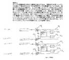
図1は、ファイバ経路に沿って進行している光学信号にゲインを与えるため、各々希土類をドープさせたファイバ1141、1142、1161および1162をそれぞれ含む4つの一方向性の光ファイバ経路1101、1102、1121および1122を示す。動力伝達装置において、ファイバ経路1101、1102、1121および1122は2つの対において配列される。そして、それぞれは双方向通信をサポートする。具体的には、第1のファイバ対110は、反対方向において進行している光学信号をサポートする一方向性ファイバ1101および1102を備える。同様に、第2のファイバ対112もまた、互いに関して反対方向において進行している光学信号をサポートする一方向性ファイバ1121、および1122を備える。FIG. 1 shows four unidirectional optical fibers each including a rare earth doped fiber 1141 , 1142 , 1161, and 1162 , respectively, to provide gain to an optical signal traveling along the fiber path. Paths 1101 , 1102 , 1121 and 1122 are shown. In the power transmission device, the fiber paths 1101 , 1102 , 1121 and 1122 are arranged in two pairs. Each supports bi-directional communication. Specifically, the first fiber pair 110 comprises unidirectional fibers 1101 and 1102 that support optical signals traveling in opposite directions. Similarly, the second fiber pair 112 also comprises unidirectional fibers 1121 and 1122 that support optical signals traveling in opposite directions with respect to each other.
本発明によれば、第1のポンプ装置は、ファイバ対110および112の各々における一方のファイバにポンプ・エネルギを供給するように提供される。
特に、2つのポンプ源1201および1202は、第1のファイバ対110のファイバ1101に位置する希土類をドープさせたファイバ1141および、第2のファイバ対112のファイバ1121に位置する希土類をドープさせたファイバ1161にポンプ・エネルギを供給する。2×2コンバイナ/スプリッタ150は、ポンプ源1201および1202により生成されたポンプ・エネルギを結合し、希土類をドープさせたファイバ1141および11
61の間で結合されたパワーを分割する。結合要素1401および1402は、2×2コンバイナ/スプリッタ150の出力口からポンプ・エネルギを受容し、ポンプ・エネルギが信号と結合されるファイバ経路1101および1121上へそれぞれポンプ・エネルギを向ける。
例えばファイバ・カプラまたは波長分割マルチプレクサと融合させることができる結合要素1401および1402は、ポンプ・エネルギ波長における高カップリング比率、および、信号波長における低カップリング比率を有するように一般に構成される。In accordance with the present invention, a first pump device is provided to supply pump energy to one fiber in each of the fiber pairs 110 and 112.
In particular, the two pump sources 1201 and 1202 are comprised of a rare earth doped fiber 1141 located in the fiber 1101 of the first fiber pair 110 and a rare earth located in the fiber 1121 of the second fiber pair 112. The pump energy is supplied to the fiber 1161 doped with. The 2 × 2 combiner /
6 Divide the combined power between1 's. Coupling elements 1401 and 1402 receive pump energy from the output of the 2 × 2 combiner /
For example, coupling elements 1401 and 1402 that can be fused with fiber couplers or wavelength division multiplexers are typically configured to have a high coupling ratio at the pump energy wavelength and a low coupling ratio at the signal wavelength. .
第1のポンプ装置と類似して、第2のポンプ装置は、ファイバ対110および112の各々における一方のファイバにポンプ・エネルギを供給するため提供される。特に、2つのポンプ源1301および1302は、第1のファイバ対110のファイバ1102に位置する希土類をドープさせたファイバ1142、および、第2のファイバ対112のファイバ1122に位置する希土類をドープさせたファイバ1162にポンプ・エネルギを供給する。2×2コンバイナ/スプリッタ160は、ポンプ源1301および1302により生成されたポンプ・エネルギを結合し、希土類をドープさせたファイバ1142および1162の間で結合されたパワーを分割する。結合要素1441および1442は、2×2コンバイナ/スプリッタ160の出力口からポンプ・エネルギを受容し、ポンプ・エネルギが信号と結合されるファイバ経路1102および1122上へそれぞれポンプ・エネルギを向ける。結合要素1401および1402のように、結合要素1441および1442は、例えば、融合されたファイバ・カプラまたは波長分割マルチプレクサを含む従来技術における当業者に公知であるいかなる適当な結合配置をも備えることができる。Similar to the first pump device, a second pump device is provided for supplying pump energy to one fiber in each of the fiber pairs 110 and 112. In particular, the two pump sources 1301 and 1302 are located in the rare earth-doped fiber 1142 located in the fiber 1102 of the first fiber pair 110 and the fiber 1122 in the second fiber pair 112. supply the pump energy to fiber 1162 was doped with rare earth. The 2 × 2 combiner / splitter 160 combines the pump energy generated by the pump sources 1301 and 1302 and splits the combined power between the rare earth doped fibers 1142 and 1162 . Coupling elements 1441 and 1442 receive pump energy from the output of the 2 × 2 combiner / splitter 160 and pump the pump energy onto fiber paths 1102 and 1122 where the pump energy is combined with the signal, respectively. Turn. Like coupling elements 1401 and 1402 , coupling elements 1441 and 1442 have any suitable coupling arrangement known to those skilled in the art including, for example, fused fiber couplers or wavelength division multiplexers. Can be provided.
本発明においては、各々のポンプ装置が異なるファイバ対に位置するファイバにパワーを提供するので、2つのポンプの故障により、2つのファイバ対の各々に沿って一方向へトラフィックが運ばれるのをなお許容する。例えば、図1に関連すると、ポンプ源1201および1202の両方の故障は、それぞれ第1のファイバ対110および第2のファイバ対112の光ファイバ1101および 1121におけるトラフィックの損失に至る。第1のファイバ対110の光ファイバ1102、および、第2のファイバ対の光ファイバ1122のトラフィックは影響を受けない。他方では、しかしながら、異なるポンプ配置の1つに位置する各々のポンプについては、2つのポンプが故障した場合、いずれのファイバ上のトラフィックは失われない。例えば、第1のポンプ配置のポンプ源1201(またはポンプ源1202)、および、第2のポンプ配置のポンプ源1301(またはポンプ源1302)の両方の故障によりファイバ1101、1102、1121および1122に供給される全体のパワーの半分が減少するだけである。したがって、4つのすべてのファイバ1101、1102、1121および1122に沿ったトラフィックの継続を許容する。In the present invention, each pumping device provides power to fibers located in different fiber pairs, so that failure of two pumps will still cause traffic to be carried in one direction along each of the two fiber pairs. Allow. For example, referring to FIG. 1, a failure of both pump sources 1201 and 1202 leads to a loss of traffic in optical fibers 1101 and 1121 offirst fiber pair 110 and second fiber pair 112, respectively. The traffic of the optical fiber 1102 of the first fiber pair 110 and the optical fiber 1122 of the second fiber pair 110 is not affected. On the other hand, however, for each pump located in one of the different pump arrangements, traffic on either fiber is not lost if two pumps fail. For example, the failure of both the pump source 1201 (or pump source 1202 ) in the first pump arrangement and the pump source 1301 (or pump source 1302 ) in the second pump arrangement causes the fibers 1101 , 1102 to fail. , 1121 and 1122 only half of the total power supplied is reduced. Thus, it allows continuation of traffic along all four fibers 1101 , 1102 , 1121 and 1122 .
図2は、図1に示されるポンプ配置におけるより高程度の代理機能性を有する構成を提供する本発明の別の実施例を示す。図1および2において、同類の要素は参照番号のように示される。本発明の本実施例において、希土類をドープさせたファイバ1141および1161を横切り、かつ、ファイバ1101および1121に沿って下流に(例えば、東回りの方向に)続く、過剰なまたは未使用の共に伝搬するポンプ・パワーは、ファイバ1102および1122に移される。ここで、過剰パワーは、希土類をドープさせたファイバ1142および1162を共に供給するため、下流(例えば、西回りの方向)に移動する。このポンプ・パワーの移送またはリサイクルは、結合要素2101、2102、2201および2202、2×2コンバイナ/スプリッタ270および280を含む受動的な連結配置によって、成し遂げられる。FIG. 2 shows another embodiment of the present invention that provides a configuration with a higher degree of surrogate functionality in the pump arrangement shown in FIG. In FIGS. 1 and 2, like elements are indicated by reference numerals. In this embodiment of the present invention, excess or uncrossed rare earth doped fibers 1141 and 1161 and continues downstream (eg, in an eastward direction) along fibers 1101 and 1121. pump power both propagating the use is transferred to the fiber 1102 and 1122. Here, excess power travels downstream (eg, westward direction) to supply both rare earth doped fibers 1142 and 1162 . This pump power transfer or recycling is accomplished by a passive coupling arrangement including
示されたように、結合要素2101および2201はそれぞれ第1のファイバ対110のファイバ1101、および、第2のファイバ対112のファイバ1121に位置する。結合要素2101および2201は、それぞれ希土類をドープさせたファイバ1141および1161の下流に位置する。
加えて、結合要素2102および2202は、それぞれ第1のファイバ対のファイバ1102および第2のファイバ対112のファイバ1122に位置する。
結合要素2102および2202は、それぞれ希土類をドープさせたファイバ1142および1162の上流に位置する。As shown,
In addition,
Coupling
動作において、2×2コンバイナ/スプリッタ270は、カプラ2101および2201から過剰なポンプ・エネルギを受容し、2×2コンバイナ/スプリッタ280の各々の入力に一部の結合されたポンプ・パワーを出力する。コンバイナ/スプリッタ280は、交替でその入力において受容されたパワーを結合し、かつ分割し、結合要素2102および2202に分割したパワーの各々の部分を向ける。このようにして、過剰なポンプ・パワーは、ファイバ1102および1122まで伝達されるので、パワーは希土類をドープさせたファイバ1142および1162までの下流に進むことができる。In operation, 2 × 2 combiner / splitter 270 receives excess pump energy from
図2に記載される受動的な連結配置は、東回りの方向において進行している過剰ポンプ・パワーをファイバ1101および1121に沿って移送するので、パワーは、ファイバ1102および1122に沿って西回りの方向において進行する。従来技術の当業者は、類似した配置が、西回りの方向においてファイバ1102および1122に沿って進行する過剰なポンプ・パワーを東回りの方向にファイバ1101および1121に沿って移すことでエルビウムをドープさせたファイバ1141および1161に供給するために使用されることができることを認識するであろう。この場合、2つの追加2×2コンバイナ/スプリッタが、4つの結合要素のうち、2つはそれぞれファイバ1101および1122に沿って希土類をドープさせたファイバ1141および1161の上流に位置し、そして、もう2つはそれぞれファイバ1102および1122に沿って希土類をドープさせたファイバ1142および1162の下流に位置するような結合要素に加えて使用される。The passive coupling arrangement described in FIG. 2 transfers excess pump power traveling in the eastward direction along fibers 1101 and 1121 , so that power is transmitted to fibers 1102 and 1122 . Along the westward direction. Those skilled in theart, a transfer arrangement which is similarkind is, along the excess pump power traveling along the fiber 1102 and 1122 in the direction of the westbound direction of eastbound fiber 1101 and 1121It will be appreciated that this can be used tofeederbium-doped fibers 1141and 1161 . In this case, two additional 2 × 2 combiner /splitter, of the four coupling elements, two rare earth was located upstreamof the fiber 1141 and 1161 which has been doped along each fiber 1101 and 1122 and it is used in addition to the coupling element such as to be located downstreamof the fiber 1142 and 1162 is doped with a rare earth along the other two each fiber 1102 and 1122.
過剰なポンプ・パワーが西回りの方向から東回りの方向へと同様に、東回りの方向から西回りの方向に移される上述した配置を使用することにより、ポンプ源1201、1202、1301および1302のうちのいずれか3つが故障した場合にも、トラフィックがファイバ対110および112のすべての4つのファイバに沿って継続させるため、充分なポンプ・パワーが、残留する使用可能なポンプ源によって供給されることができる。このようにして、すべての4つのポンプ源が4つのファイバ上において完全にトラフィックを失うことがないので、高程度の信頼性を獲得することができる。By using the arrangement described above in which excess pump power is transferred from the eastward direction to the westward direction as well as from the westward direction to the eastward direction, the pump sources 1201 , 1202 , 130 evenwhen 1 and 130 any 3 of the2 but failed, because to continue along all four fibers traffic fiber pair 110 and 112, sufficient pump power is available residual pump Can be supplied by source. In this way, a high degree of reliability can be obtained because all four pump sources do not lose traffic completely on four fibers.
Claims (7)
Translated fromJapanese各々が、2つの双方向性の光ファイバの対である光ファイバ対を形成する異なる一方向性の光ファイバに設けられ、前記各光ファイバにおいて進行している光学信号に光学増幅を供給する4つの光増幅器と、
第1の前記光ファイバ対における第1の光ファイバ、および、第2の前記光ファイバ対における第2の光ファイバにポンプ・エネルギを提供するための第1の複数のポンプ源であって、前記第1の光ファイバおよび前記第2の光ファイバは、共通の方向に進行している光学信号をサポートする、ポンプ源と、
前記第1の複数のポンプ源から前記ポンプ・エネルギを結合し、かつ、それを前記第1および前記第2の光ファイバの前記光増幅器に分配する第1のコンバイナ配置と、
前記第1の光ファイバ対における第3の光ファイバ、および、前記第2の光ファイバ対における第4の光ファイバにポンプ・エネルギを提供するための第2の複数のポンプ源であって、前記第3の光ファイバおよび前記第4の光ファイバは、前記第1および第2の光ファイバの方向とは反対の共通の方向に進行している光学信号をサポートするポンプ源と、
前記第2の複数のポンプ源から前記ポンプ・エネルギを結合し、かつ、それを前記第3および前記第4の光ファイバの前記光増幅器に分配する第2のコンバイナ配置と、
前記第1および前記第2の光ファイバの前記光増幅器を伝播する過剰なポンプ・エネルギを結合し、前記結合された過剰なポンプ・エネルギを前記第3および前記第4の光ファイバの、前記第3および前記第4の光ファイバの前記光増幅器より上流の位置に分割して伝達する第1の受動的な連結配置と、
前記第3および前記第4の光ファイバの前記光増幅器を伝播する過剰なポンプ・エネルギを結合し、前記結合された過剰なポンプ・エネルギを前記第1および前記第2の光ファイバの、前記第1および前記第2の光ファイバの前記光増幅器より上流の位置に分割して伝達する第2の受動的な連結配置と、
からなる光学自動中継装置。An optical automatic relay device,
Eachprovided to a different unidirectional optical fiber to form an optical fiber pair is a pair oftwo bidirectional optical fiber,you supplying optical amplification to optical signals progressing in each of the optical fiberFour optical amplifiers,
A first plurality of pump sources for providing pump energy to a first optical fiber in a first pair of optical fibers and a second optical fiber in a second pair of optical fibers comprising: A first optical fiber and the second optical fiber, the pump source supporting optical signals traveling in a common direction;
A first combiner arrangement that couples the pump energy from the first plurality of pump sources and distributes it to the optical amplifiers of the first and second optical fibers;
A second plurality of pump sources for providing pump energy to a third optical fiber in the first optical fiber pair and a fourth optical fiber in the second optical fiber pair, A third optical fiber and the fourth optical fiber, wherein the pump source supports an optical signal traveling in a common direction opposite to the direction of the first and second optical fibers;
A second combiner arrangement that couples the pump energy from the second plurality of pump sources and distributes it to the optical amplifiers of the third and fourth optical fibers;
Combining excess pump energy propagating through the optical amplifiers of the first and second optical fibers, andcombining the combined excess pump energy with the third and fourth optical fibers of the first and second optical fibers; A first passive coupling arrangement forsplitting and transmitting to a position upstream of the optical amplifier of the third and fourth optical fibers;
Combine excess pump energy propagating through the optical amplifiers of the third and fourth optical fibers, andcombine the combined excess pump energy with the first and second optical fibers of the first and second optical fibers. A second passive coupling arrangement forsplitting and transmitting to a position upstream of the optical amplifier of the first and second optical fibers;
An optical automatic relay device.
Applications Claiming Priority (3)
| Application Number | Priority Date | Filing Date | Title |
|---|---|---|---|
| US40471902P | 2002-08-20 | 2002-08-20 | |
| US60/404,719 | 2002-08-20 | ||
| PCT/US2003/026106WO2004019458A2 (en) | 2002-08-20 | 2003-08-20 | Sharing pump energy among different fiber pairs |
Publications (3)
| Publication Number | Publication Date |
|---|---|
| JP2005536892A JP2005536892A (en) | 2005-12-02 |
| JP2005536892A5 JP2005536892A5 (en) | 2009-12-03 |
| JP4798997B2true JP4798997B2 (en) | 2011-10-19 |
Family
ID=31946750
Family Applications (1)
| Application Number | Title | Priority Date | Filing Date |
|---|---|---|---|
| JP2004531148AExpired - Fee RelatedJP4798997B2 (en) | 2002-08-20 | 2003-08-20 | Method and apparatus for distributing pump energy from a single pump device to optical fibers located in different pairs of fibers |
Country Status (8)
| Country | Link |
|---|---|
| US (1) | US6930825B2 (en) |
| EP (1) | EP1535411B1 (en) |
| JP (1) | JP4798997B2 (en) |
| CN (1) | CN100512057C (en) |
| AU (1) | AU2003268137A1 (en) |
| CA (1) | CA2496310A1 (en) |
| NO (1) | NO20051449L (en) |
| WO (1) | WO2004019458A2 (en) |
Families Citing this family (12)
| Publication number | Priority date | Publication date | Assignee | Title |
|---|---|---|---|---|
| JP4122884B2 (en)* | 2002-07-30 | 2008-07-23 | 日本電気株式会社 | Optical repeater |
| US20060140633A1 (en)* | 2004-12-28 | 2006-06-29 | Sanmina-Sci Corporation | Systems and methods for optical pump redundancy |
| US20060251423A1 (en)* | 2005-05-09 | 2006-11-09 | Evangelides Stephen G Jr | Method and apparatus for identifying pump failures using an optical line interface |
| CN105529604A (en)* | 2016-02-26 | 2016-04-27 | 昂纳信息技术(深圳)有限公司 | Pump-sharing optical fiber amplifier |
| KR102472525B1 (en) | 2016-03-22 | 2022-11-29 | 라이트루프 테크놀로지스, 엘엘씨 | Data in motion storage system and method |
| CN109390839B (en)* | 2017-08-11 | 2021-08-27 | 珠海保税区光联通讯技术有限公司 | Optical module and erbium-doped fiber amplifier |
| JP2021532526A (en) | 2018-08-02 | 2021-11-25 | ライトループ・テクノロジーズ・エルエルシーLyteloop Technologies, Llc | Devices and methods for storing wave signals in cavities |
| ES2939349T3 (en) | 2018-08-10 | 2023-04-21 | Nkb Properties Man Llc | System and method for extending the path length of a wave signal by angular multiplexing |
| US11955764B2 (en)* | 2018-08-27 | 2024-04-09 | Hmn Technologies Co., Limited | Submarine network device |
| US11405110B2 (en)* | 2018-10-18 | 2022-08-02 | Nec Corporation | Optical repeater and optical signal relay method |
| CN109327261B (en)* | 2018-10-18 | 2021-05-11 | 武汉光迅电子技术有限公司 | Optical path structure of an optical repeater |
| AU2019377800A1 (en) | 2018-11-05 | 2021-03-18 | Nkb Properties Management, Llc | Systems and methods for building, operating and controlling multiple amplifiers, regenerators and transceivers using shared common components |
Family Cites Families (9)
| Publication number | Priority date | Publication date | Assignee | Title |
|---|---|---|---|---|
| DK220690A (en)* | 1990-09-14 | 1992-03-15 | Nordiske Kabel Traad | OPTICAL FIBER AMPLIFIER WITH CONNECTION OF PUMP ENERGY FROM MULTIPLE PUMP SOURCES |
| US5173957A (en) | 1991-09-12 | 1992-12-22 | At&T Bell Laboratories | Pump redundancy for optical amplifiers |
| US5241414A (en)* | 1992-08-21 | 1993-08-31 | At&T Bell Laboratories | Fault tolerant optical amplifier arrangement |
| JP2546494B2 (en)* | 1993-04-28 | 1996-10-23 | 日本電気株式会社 | Bidirectional pumping optical amplifier |
| JP2928149B2 (en)* | 1995-12-14 | 1999-08-03 | 日本電気株式会社 | Optical fiber amplifier |
| US5801858A (en)* | 1996-06-25 | 1998-09-01 | Northern Telecom Limited | Optical transmission systems using optical amplifiers and wavelength division multiplexing |
| US5815613A (en)* | 1996-12-31 | 1998-09-29 | Lucent Technologies Inc. | Optical switched distributor |
| US20020057477A1 (en)* | 2000-10-25 | 2002-05-16 | Corrado Rocca | Underwater optical transmission system and switchable underwater repeater |
| JP4626918B2 (en)* | 2001-03-02 | 2011-02-09 | 富士通株式会社 | Raman optical repeater |
- 2003
- 2003-08-20CACA002496310Apatent/CA2496310A1/ennot_activeAbandoned
- 2003-08-20EPEP03749086.9Apatent/EP1535411B1/ennot_activeExpired - Lifetime
- 2003-08-20CNCNB038222329Apatent/CN100512057C/ennot_activeExpired - Lifetime
- 2003-08-20WOPCT/US2003/026106patent/WO2004019458A2/enactiveApplication Filing
- 2003-08-20AUAU2003268137Apatent/AU2003268137A1/ennot_activeAbandoned
- 2003-08-20USUS10/646,351patent/US6930825B2/ennot_activeExpired - Lifetime
- 2003-08-20JPJP2004531148Apatent/JP4798997B2/ennot_activeExpired - Fee Related
- 2005
- 2005-03-18NONO20051449Apatent/NO20051449L/ennot_activeApplication Discontinuation
Also Published As
| Publication number | Publication date |
|---|---|
| CN1682471A (en) | 2005-10-12 |
| WO2004019458A9 (en) | 2004-05-06 |
| EP1535411A4 (en) | 2006-02-01 |
| WO2004019458A2 (en) | 2004-03-04 |
| AU2003268137A1 (en) | 2004-03-11 |
| CN100512057C (en) | 2009-07-08 |
| NO20051449L (en) | 2005-05-19 |
| US20040136056A1 (en) | 2004-07-15 |
| US6930825B2 (en) | 2005-08-16 |
| JP2005536892A (en) | 2005-12-02 |
| AU2003268137A8 (en) | 2004-03-11 |
| EP1535411B1 (en) | 2013-10-16 |
| CA2496310A1 (en) | 2004-03-04 |
| EP1535411A2 (en) | 2005-06-01 |
| WO2004019458A3 (en) | 2005-04-07 |
Similar Documents
| Publication | Publication Date | Title |
|---|---|---|
| EP1248392B1 (en) | Optical amplifier device and bidirectional wavelength division multiplexing optical communication system using the same | |
| US6941074B2 (en) | Bidirectionally transmittable optical wavelength division multiplexed transmission system | |
| EP1263096B1 (en) | Improved wide band erbium-doped fiber amplifier (EDFA) | |
| US20240178629A1 (en) | Gain equalization in c+l erbium-doped fiber amplifiers | |
| US6031646A (en) | Optical fiber telecommunication system | |
| JP4798997B2 (en) | Method and apparatus for distributing pump energy from a single pump device to optical fibers located in different pairs of fibers | |
| JP3779691B2 (en) | Broadband erbium-doped optical fiber amplifier and wavelength division multiplexing optical transmission system employing the same | |
| US6359728B1 (en) | Pump device for pumping an active fiber of an optical amplifier and corresponding optical amplifier | |
| US8233216B2 (en) | Optical amplifier bandwidth alteration | |
| US6236777B1 (en) | Reliability of an optical communication system and of an optical amplifying system, and a method suitable to this aim | |
| JP3745721B2 (en) | Dispersion compensation optical fiber amplifier | |
| KR100592880B1 (en) | Parallel Raman Optical Amplifier | |
| JP4095159B2 (en) | Optical communication system and optical amplification system | |
| US7145716B2 (en) | Multiple stage Raman optical amplifier | |
| KR20030075295A (en) | An Gain clamped erbium-doped fiber amplifier for long wavelength band | |
| US6567208B1 (en) | Amplification of a C-band and L-band of a optical signal using a common laser signal | |
| EP0878927B1 (en) | Improvement in the reliability of an optical communication system and a method suitable to this aim | |
| US20020122243A1 (en) | Distributed gain optical fiber amplifier | |
| WO2005124446A1 (en) | Optical amplifier and optical communication system | |
| JP2004037920A (en) | Apparatus for Raman amplification and optical transmission system using Raman amplification | |
| WO1998052305A1 (en) | Redundant optical power supply for remote pumping of fiber optic gain modules | |
| WO2000049741A1 (en) | Method and apparatus for providing optical amplification and gain equalization to an optical signal in an optical communication system |
Legal Events
| Date | Code | Title | Description |
|---|---|---|---|
| A621 | Written request for application examination | Free format text:JAPANESE INTERMEDIATE CODE: A621 Effective date:20060817 | |
| A711 | Notification of change in applicant | Free format text:JAPANESE INTERMEDIATE CODE: A711 Effective date:20081114 | |
| A521 | Request for written amendment filed | Free format text:JAPANESE INTERMEDIATE CODE: A523 Effective date:20081226 | |
| A072 | Dismissal of procedure [no reply to invitation to correct request for examination] | Free format text:JAPANESE INTERMEDIATE CODE: A073 Effective date:20090609 | |
| A131 | Notification of reasons for refusal | Free format text:JAPANESE INTERMEDIATE CODE: A131 Effective date:20090623 | |
| A711 | Notification of change in applicant | Free format text:JAPANESE INTERMEDIATE CODE: A711 Effective date:20090904 | |
| A524 | Written submission of copy of amendment under article 19 pct | Free format text:JAPANESE INTERMEDIATE CODE: A524 Effective date:20090915 | |
| A521 | Request for written amendment filed | Free format text:JAPANESE INTERMEDIATE CODE: A821 Effective date:20090904 | |
| A02 | Decision of refusal | Free format text:JAPANESE INTERMEDIATE CODE: A02 Effective date:20100216 | |
| A521 | Request for written amendment filed | Free format text:JAPANESE INTERMEDIATE CODE: A523 Effective date:20110701 | |
| A01 | Written decision to grant a patent or to grant a registration (utility model) | Free format text:JAPANESE INTERMEDIATE CODE: A01 | |
| A61 | First payment of annual fees (during grant procedure) | Free format text:JAPANESE INTERMEDIATE CODE: A61 Effective date:20110802 | |
| FPAY | Renewal fee payment (event date is renewal date of database) | Free format text:PAYMENT UNTIL: 20140812 Year of fee payment:3 | |
| R150 | Certificate of patent or registration of utility model | Ref document number:4798997 Country of ref document:JP Free format text:JAPANESE INTERMEDIATE CODE: R150 Free format text:JAPANESE INTERMEDIATE CODE: R150 | |
| R250 | Receipt of annual fees | Free format text:JAPANESE INTERMEDIATE CODE: R250 | |
| R250 | Receipt of annual fees | Free format text:JAPANESE INTERMEDIATE CODE: R250 | |
| R250 | Receipt of annual fees | Free format text:JAPANESE INTERMEDIATE CODE: R250 | |
| R250 | Receipt of annual fees | Free format text:JAPANESE INTERMEDIATE CODE: R250 | |
| R250 | Receipt of annual fees | Free format text:JAPANESE INTERMEDIATE CODE: R250 | |
| R250 | Receipt of annual fees | Free format text:JAPANESE INTERMEDIATE CODE: R250 | |
| R250 | Receipt of annual fees | Free format text:JAPANESE INTERMEDIATE CODE: R250 | |
| R250 | Receipt of annual fees | Free format text:JAPANESE INTERMEDIATE CODE: R250 | |
| LAPS | Cancellation because of no payment of annual fees |