JP4798287B2 - Electrical equipment - Google Patents
Electrical equipmentDownload PDFInfo
- Publication number
- JP4798287B2 JP4798287B2JP2009520722AJP2009520722AJP4798287B2JP 4798287 B2JP4798287 B2JP 4798287B2JP 2009520722 AJP2009520722 AJP 2009520722AJP 2009520722 AJP2009520722 AJP 2009520722AJP 4798287 B2JP4798287 B2JP 4798287B2
- Authority
- JP
- Japan
- Prior art keywords
- plate
- opening
- partition member
- housing
- side plate
- Prior art date
- Legal status (The legal status is an assumption and is not a legal conclusion. Google has not performed a legal analysis and makes no representation as to the accuracy of the status listed.)
- Active
Links
Images


Classifications
- H—ELECTRICITY
- H05—ELECTRIC TECHNIQUES NOT OTHERWISE PROVIDED FOR
- H05K—PRINTED CIRCUITS; CASINGS OR CONSTRUCTIONAL DETAILS OF ELECTRIC APPARATUS; MANUFACTURE OF ASSEMBLAGES OF ELECTRICAL COMPONENTS
- H05K7/00—Constructional details common to different types of electric apparatus
- H05K7/20—Modifications to facilitate cooling, ventilating, or heating
- H05K7/20009—Modifications to facilitate cooling, ventilating, or heating using a gaseous coolant in electronic enclosures
- H05K7/20136—Forced ventilation, e.g. by fans
- H05K7/20154—Heat dissipaters coupled to components
- H05K7/20163—Heat dissipaters coupled to components the components being isolated from air flow, e.g. hollow heat sinks, wind tunnels or funnels
- B—PERFORMING OPERATIONS; TRANSPORTING
- B23—MACHINE TOOLS; METAL-WORKING NOT OTHERWISE PROVIDED FOR
- B23K—SOLDERING OR UNSOLDERING; WELDING; CLADDING OR PLATING BY SOLDERING OR WELDING; CUTTING BY APPLYING HEAT LOCALLY, e.g. FLAME CUTTING; WORKING BY LASER BEAM
- B23K9/00—Arc welding or cutting
- B23K9/32—Accessories
- H—ELECTRICITY
- H05—ELECTRIC TECHNIQUES NOT OTHERWISE PROVIDED FOR
- H05K—PRINTED CIRCUITS; CASINGS OR CONSTRUCTIONAL DETAILS OF ELECTRIC APPARATUS; MANUFACTURE OF ASSEMBLAGES OF ELECTRICAL COMPONENTS
- H05K7/00—Constructional details common to different types of electric apparatus
- H05K7/20—Modifications to facilitate cooling, ventilating, or heating
- H05K7/20009—Modifications to facilitate cooling, ventilating, or heating using a gaseous coolant in electronic enclosures
- H05K7/20136—Forced ventilation, e.g. by fans
- H05K7/20145—Means for directing air flow, e.g. ducts, deflectors, plenum or guides
- H—ELECTRICITY
- H05—ELECTRIC TECHNIQUES NOT OTHERWISE PROVIDED FOR
- H05K—PRINTED CIRCUITS; CASINGS OR CONSTRUCTIONAL DETAILS OF ELECTRIC APPARATUS; MANUFACTURE OF ASSEMBLAGES OF ELECTRICAL COMPONENTS
- H05K7/00—Constructional details common to different types of electric apparatus
- H05K7/20—Modifications to facilitate cooling, ventilating, or heating
- H05K7/2089—Modifications to facilitate cooling, ventilating, or heating for power electronics, e.g. for inverters for controlling motor
- H05K7/20909—Forced ventilation, e.g. on heat dissipaters coupled to components
- H05K7/20918—Forced ventilation, e.g. on heat dissipaters coupled to components the components being isolated from air flow, e.g. hollow heat sinks, wind tunnels or funnels
Landscapes
- Engineering & Computer Science (AREA)
- Microelectronics & Electronic Packaging (AREA)
- Physics & Mathematics (AREA)
- Thermal Sciences (AREA)
- Plasma & Fusion (AREA)
- Mechanical Engineering (AREA)
- Cooling Or The Like Of Electrical Apparatus (AREA)
Description
Translated fromJapanese本発明は、例えば、溶接に使用される溶接装置等の、冷却ファンを用いて内部の冷却を行う電気機器に関するものである。 The present invention relates to an electrical apparatus that cools an inside using a cooling fan, such as a welding apparatus used for welding.
従来、溶接装置のような電気機器おいて、電気機器を冷却する方法として、筐体に吸気孔と排気孔を設け、ファンにより電気機器内部を冷却するものが知られている(例えば、特許文献1参照)。また、機器の冷却を行うために、筐体を構成する前後や左右のいずれかの側板に開口部を備えた溶接装置が知られている(例えば、特許文献2参照)。 2. Description of the Related Art Conventionally, in an electric device such as a welding apparatus, as a method of cooling an electric device, an air intake hole and an exhaust hole are provided in a housing and the inside of the electric device is cooled by a fan (for example, Patent Document 1). Moreover, in order to cool an apparatus, the welding apparatus provided with the opening part in the side plate either before and after which comprises a housing | casing, or right and left is known (for example, refer patent document 2).
このような従来の技術からさらに良好に冷却を行える電気機器として、図5に示すような電気機器が考えられる。 As an electric device that can be cooled more satisfactorily than such a conventional technique, an electric device as shown in FIG. 5 can be considered.
図5に示す電気機器は、前面板31と左側板32と右側板33と後面板34を有する筐体40を備えている。後面板34には、筐体40内の熱せられた空気を筐体40外に排出するための第1の開口部37が設けられている。左側板32には、筐体40外から筐体40内に空気を取り込むための第2の開口部38が設けられている。右側板33には、筐体40外から筐体40内に空気を取り込むための第3の開口部39が設けられている。筐体40内には、発熱性素子15が配置されている。さらに、筐体40内には、筐体40内の熱せられた空気を筐体40の外に排出するファン36を備えている。 The electric apparatus shown in FIG. 5 includes a
しかし、このような従来技術から考えられる電気機器で溶接装置等を構成した場合は、熱をもった溶接スパッタやグラインダー等で発生する赤熱した鉄粉等が直接電気機器の開口部から内部に侵入する可能性がある。たとえ、開口部37〜39にルーバーが設けられていても、飛散する角度によっては赤熱したまま侵入する可能性がある。 However, when a welding apparatus is configured with such electrical equipment considered from the prior art, red hot iron powder generated by hot welding spatters and grinders directly penetrates into the interior from the opening of the electrical equipment. there's a possibility that. For example, even if louvers are provided in the
本発明は、熱を持った溶接スパッタ等が飛散して電気機器の開口部に侵入しても、直接電気機器内部に入ることを抑制する安全性の高い電気機器を提供するものである。 The present invention provides a highly safe electric device that suppresses direct entry into the electric device even if heat-welded spatter or the like is scattered and enters the opening of the electric device.
本発明は、前面板と左側面板と右側面板と後面板と上面板と下面板とを有する筐体と、前面板と左側面板と右側面板と後面板と上面板と下面板のうちのいずれかの面板に設けられ筐体内の空気を筐体外に排出するための排出用開口部と、排出用開口部が設けられていない面板のうちの少なくともひとつの面板に設けられ筐体外から筐体内に空気を取り込むための取り込み用開口部と、取り込み用開口部が設けられた面板との間に空気経路を形成するように筐体内に設けられ、取り込み用開口部と重ならない位置に空気を取り込むための他の取り込み用開口部を有する仕切り部材と、空気を流通させるための空洞部を形成する外周部を有し、空洞部の一端側の開口部が排出用開口部に面するように、仕切り部材と排出用開口部が形成された面板との間に配置された放熱ユニットと、筐体内に配置された発熱性素子と、筐体内の熱せられた空気を筐体外に排出する送風部とを備えた構成を有する。 The present invention is any one of a front plate, a left side plate, a right side plate, a rear plate, a top plate and a bottom plate, a front plate, a left side plate, a right side plate, a rear plate, a top plate and a bottom plate. The air is provided on at least one face plate of the face plate provided with the face plate not provided with the discharge opening for discharging the air inside the case to the outside of the case and the face plate not provided with the discharge opening. Is provided in the housing so as to form an air path between the intake opening for taking in and the face plate provided with the intake opening, and for taking in air at a position that does not overlap the intake opening. A partition member having another intake opening and an outer peripheral portion forming a cavity for circulating air, and the opening on one end side of the cavity faces the discharge opening And face plate with discharge opening Has a heat dissipating unit disposed between the, and the heat generating element disposed in the housing, the configuration of the air heated with the housing and a blower unit for discharging outside the housing.
このような構成によれば、例えば溶接中に溶接スパッタ類が飛散して電気機器の開口部に侵入しても、一旦仕切り部材に飛散物が当たる。そのため、溶接スパッタ類等が電子部品等を備えた電気機器内部に直接入ることを抑制することができ、安全性の高い電気機器を実現することができる。 According to such a configuration, for example, even if welding spatter is scattered during welding and enters the opening of the electric device, the scattered material once hits the partition member. Therefore, it is possible to suppress welding spatters and the like from directly entering the inside of an electric device provided with an electronic component and the like, and a highly safe electric device can be realized.
(実施の形態1)
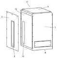
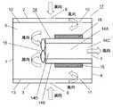
以下、本発明の実施の形態について、図1から図3を用いて説明する。図1は本実施の形態における電気機器の一例である溶接装置の概観を示す概要図である。構造がわかり易いように後述する左側板2を分解した状態を示している。図2は本実施の形態における電気機器を上面から見た要部概略断面図である。図3は本実施の形態における電気機器を約半分の高さで切断し斜め方向からみた場合の要部概略断面図である。(Embodiment 1)
Hereinafter, embodiments of the present invention will be described with reference to FIGS. 1 to 3. FIG. 1 is a schematic diagram showing an overview of a welding apparatus which is an example of an electrical apparatus in the present embodiment. The state which decomposed | disassembled the
図1から図3において、筐体17は、前面板1と左側板2と右側板3と後面板4と上面板5と下面板6とを備えている。筐体17を載置面に載置した場合、載置面に垂直な1つの面を前面板1とした場合、載置面に垂直な面で前面板1に接続される2つの板を左側板2および右側板3とし、載置面に垂直な面で前面板1と対向する位置の板を後面板4とする。また、載置面と略平行(以下、略平行は平行の場合も含む)であり前面板1と左側板2と右側板3と後面板4に接する1つの面を上面板5とする。さらに、載置面と略平行であり前面板1と左側板2と右側板3と後面板4に接し上面板5と対向する位置にあり上面板5よりも載置面に近い板を下面板6とする。 1 to 3, the
後面板4には筐体17内の空気を筐体17の外に排出するための第1の開口部(排出用開口部)7が設けられている。左側板2には筐体17の外から筐体内17の内部に空気を取り込むための第2の開口部(取り込み用開口部)8が設けられている。第2の開口部8の横方向(前後方向)の中心位置は、左側板2の横方向の中心位置と略同一(以下、略同一は同一の場合も含む)である。また、右側板3には筐体17の外から筐体17の内部に空気を取り込むための第3の開口部(取り込み用開口部)9が設けられている。第3の開口部9の横方向の中心位置は、右側板3の横方向の中心位置と略同一である。 The
また、筐体17の内部には左側板2に略平行であり上面板5と下面板6と前面板1と後面板4とに接している第1の仕切り部材12が設けられている。第1の仕切り部材12は、第2の開口部8から取り込まれた空気を、筐体17の内部に空気を取り込むための第4の開口部(他の取り込み用開口部)10を有している。また、右側板3に略平行で上面板5と下面板6と前面板1と後面板4とに接している第2の仕切り部材13が設けられている。第2の仕切り部材13は、第3の開口部9から取り込まれた空気を、筐体17の内部に空気を取り込むための第5の開口部(他の取り込み用開口部)11を有している。 A
第4の開口部10は、第2の開口部8と重ならないように第2の開口部8よりも後面板4側に設けられている。同様に、第5の開口部11は、第3の開口部9と重ならないように第3の開口部9よりも後面板4側に設けられている。このように、本実施の形態では、第4の開口部10の中心位置は第1の仕切り部材12の中心位置より後面板4側である。第5の開口部11の中心位置は第2の仕切り部材13の中心位置より後面板4側である。第2の開口部8は第4の開口部10より前面板1側であり、第3の開口部9は第5の開口部11より前面板1側である。すなわち、第1の仕切り部材12は、第2の開口部8を覆うように左側板2に略平行に筺体17内に設けられている。同様に、第2の仕切り部材13は、第3の開口部9を覆うように右側板3に略平行に筐体17内に設けられている。 The
第1の仕切り部材12と第2の仕切り部材13との間には、放熱ユニット14が配置されている。放熱ユニット14は、内部に空気を流通させるための空洞部14Aを形成する外周部14Bを備えたトンネル形状を呈している。空洞部14Aは、角型筒状を呈しており、本実施の形態では、上下2段に形成されている。この空洞部14Aは、1段でもいし、3段以上でもよい。放熱ユニット14の一端側の開口部14Cは後面板4の第1の開口部7に面するように配置されている。放熱ユニット14の外周面には発熱性素子15が取り付けられている。発熱性素子15は、例えば溶接装置に使用する溶接出力をインバータ制御するためのスイッチング素子等として動作する半導体素子等の電子部品である。したがって、溶接装置が動作するときにはスイッチング素子等が駆動され、熱を発する。したがって、発熱性素子15が発熱源となって筐体17内が加熱される。発熱性素子15は、スイッチング素子以外にもパワートランジスタなどが挙げられる。なお、発熱性素子15は、放熱ユニット14から離れた位置に設けるようにしても良い。空洞部14内には、内部の放熱効果を高めるためにヒダ状のヒートシンク18(図3)が設けられている。 A
また、放熱ユニット14の開口部14Cとは反対側の開口部14Dには、筐体17内の熱せられた空気を筐体17の外部に排出する送風部としてのファン16が設けられている。なお、ファン16は、放熱ユニット14の開口部14Cに設けても良いし、放熱ユニット14の両方の開口部14C、4Dに設けても良いし、放熱ユニット14の内部に設けるようにしても良い。また、ファン16は、第2の開口部8と第3の開口部9、あるいは、第4の開口部10と第5の開口部11、あるいは、第2の開口部8と第3の開口部9と第4の開口部10と第5の開口部11に設けても良い。また、ファン16は、これら取り付け位置の任意の組み合わせの位置に設けても良い。さらに、ファン16は、上下の各空洞部14A毎に設けても良い。すなわち、ファン16は、筐体17内の空気が放熱ユニット14内を通って第1の開口部7から筐体17の外部に排出可能な位置に設けられれば良い。 In addition, a
次に、上記のように構成された電気機器の冷却に関する動作について、溶接装置の場合を例にして説明する。図示しない電気機器の起動スイッチを押すことにより電気機器が動作を開始し、発熱性素子15が動作するとともに発熱する。したがって、筐体17内の冷却のために起動スイッチの押下に伴ってファン16が駆動する。あるいは、起動スイッチの押下後、筐体17内が所定の温度に達したときにファン16が駆動する。 Next, the operation relating to the cooling of the electrical equipment configured as described above will be described by taking the case of a welding apparatus as an example. When an activation switch of an electric device (not shown) is pressed, the electric device starts operating, and the
ファン16が駆動することにより第2の開口部8から筐体17内に空気が取り込まれ、この取り込まれた空気は第2の開口部8よりも後面板4側にある第4の開口部10から内部に取り込まれる。この取り込まれた空気は、後面板4側から前面板1側へ流れ、放熱ユニット14内を通って第1の開口部7から筐体17の外部に排出される。同様に、ファン16が駆動することにより第3の開口部9から筐体17内に空気が取り込まれ、この取り込まれた空気は第3の開口部9よりも後面板4側にある第5の開口部11から内部に取り込まれる。そして、この取り込まれた空気は、後面板4側から前面板1側へ流れ、放熱ユニット14内を通って第1の開口部7から筐体17の外部に排出される。 When the
本実施の形態では、第4の開口部10の中心位置を第1の仕切り部材12の中心位置より後面板4側にし、第5の開口部11の中心位置を第2の仕切り部材13の中心位置より後面板4側にした。しかし、第4の開口部10の中心位置を第1の仕切り部材12の中心位置と同じにし、第5の開口部11の中心位置を第2の仕切り部材13の中心位置と同じにしても良い。すなわち、このような場合でも、第2の開口部8を第4の開口部10より前面板1側に、第3の開口部9を第5の開口部11より前面板1側に形成すれば、本実施の形態と同様の空気の流れが筺体17内に発生する。 In the present embodiment, the center position of the
これにより筐体17内を冷却することが可能となる。取り込まれた空気は、後面板4側から前面板1側へ、さらに放熱ユニット14内を後面板4側へ空気が流れる。したがって、放熱ユニット14だけでなく発熱性素子15の表面も冷却することができ、また、筐体17内全体を空気が流れるので筐体17を効率的に冷却することができる。 As a result, the inside of the
また、溶接作業を行っている場合、ファン16が動作して筐体17内に空気を取り込むことに併せ、第2の開口部8や第3の開口部9から熱をもったスパッタ等も筐体17内に取り込まれる可能性もある。しかし、第4の開口部10は第2の開口部8と重ならない位置に設けているので、仮に第2の開口部8から熱をもったスパッタ等が入ってきたとしても、第1の仕切り部材12に当たることとなる。同様に、第5の開口部11は第3の開口部9と重ならない位置に設けているので、仮に第3の開口部9から熱をもったスパッタ等が入ってきたとしても、第2の仕切り部材13に当たることとなる。これにより、発熱性素子15を備えた電気機器内部にスパッタ等が入ってくることを抑制することができ、電気機器の安全を保つことができる。 In addition, when welding work is performed, the
以上のように、本実施の形態の電気機器によれば、筐体17内の冷却効率を高めると共に、熱を持ったスパッタ等が筐体17内に入ることを抑制して電気機器の安全性を保つことができる。 As described above, according to the electrical device of the present embodiment, the cooling efficiency in the
なお、上記した電気機器において、放熱ユニット14は、空洞部14A毎に、発熱源としての異なる発熱性素子15を取り付けて効率よく発熱性素子15が発する熱を排出するようにしても良い。そしてこの場合、前述したように、空洞部毎にファン16を設けることが望ましい。 In the above-described electrical apparatus, the
また、第2の開口部8を左側板2の高さと略同一の高さの開口部とし、第3の開口部9を右側板3の高さと略同一の高さの開口部とすることにより、開口部の幅が同じ場合、筐体17内により多くの空気を取り込むことが可能となる。 Further, the
また、第1の仕切り部材12は、上面板5と下面板6と前面板1とに接し、後面板4とは接しない構造とすることで、第1の仕切り部材12と後面板4との間隙を第4の開口部10としても良い。同様に、第2の仕切り部材13は、上面板5と下面板6と前面板1とに接し、後面板4とは接しない構造とすることで、第2の仕切り部材13と後面板4との間隙を第5の開口部11としても良い。 In addition, the
さらに、本実施の形態では、第2の開口部8を第4の開口部10より前面板1側に、第3の開口部9を第5の開口部11より前面板1側に、それぞれ設けた。しかし、第4の開口部10を第2の開口部8より前面板1側に、第5の開口部11を第3の開口部9より前面板1側に、それぞれ設けても、第1の仕切り部材12が第2の開口部8を、第2の仕切り部材13が第3の開口部9を、それぞれ覆っている。したがって、筐体17内の冷却効率を高めると共に、熱を持ったスパッタ等が筐体17内に入ることを抑制して電気機器の安全性を保つことができる。この場合、発熱性素子15を筺体17内の空気の流れの中に配置すれば、発熱性素子15が発する熱を効率よく排出できる。 Further, in the present embodiment, the
図4は本実施の形態の電気機器の他の例を示す部分透過斜視図である。図4に示す電気機器は、例えば上面板5により上下2つの領域に分割されている。上面板5の上側の領域は完全な防塵領域20である。上面板5を含む上面板5から下側の領域は、上記で説明した筐体17の構造を有する冷却領域21である。このように、防塵領域20と冷却領域21とを有する構造として電気機器を構成しても良い。 FIG. 4 is a partially transparent perspective view showing another example of the electric apparatus of the present embodiment. The electric device shown in FIG. 4 is divided into two upper and lower regions by, for example, the
本発明は、内部の安全性を向上することができるので、溶接機分野等、冷却ファンにより冷却を行う機器、特に飛散物が存在する作業環境で使用する電気機器として有用である。 Since the internal safety can be improved, the present invention is useful as a device for cooling by a cooling fan such as in the field of a welding machine, particularly as an electric device used in a working environment where scattered objects exist.
1 前面板
2 左側板
3 右側板
4 後面板
5 上面板
6 下面板
7 第1の開口部
8 第2の開口部
9 第3の開口部
10 第4の開口部
11 第5の開口部
12 第1の仕切り部材
13 第2の仕切り部材
14 放熱ユニット
14A 空洞部
14B 外周部
14C,14D 開口部
15 発熱性素子
16 ファン
17 筐体
20 防塵領域
21 冷却領域DESCRIPTION OF
Claims (9)
Translated fromJapanese前記前面板と前記左側面板と前記右側面板と前記後面板と前記上面板と前記下面板のうちのいずれかの面板に設けられ前記筐体内の空気を前記筐体外に排出するための排出用開口部と、
前記排出用開口部が設けられていない面板のうちの少なくともひとつの面板に設けられ前記筐体外から前記筐体内に前記空気を取り込むための取り込み用開口部と、
前記取り込み用開口部が設けられた面板との間に空気経路を形成するように前記筐体内に設けられ、前記取り込み用開口部と重ならない位置に前記空気を取り込むための他の取り込み用開口部を有する仕切り部材と、
前記空気を流通させるための空洞部を形成する外周部を有し、前記空洞部の一端側の開口部が前記排出用開口部に面するように、前記仕切り部材と前記排出用開口部が形成された面板との間に配置された放熱ユニットと、
前記筐体内に配置された発熱性素子と、
前記筐体内の熱せられた前記空気を前記筐体外に排出する送風部とを備え、
前記排出用開口部が、前記後面板に設けられた第1の開口部からなり、
前記取り込み用開口部が、前記左側板に設けられた第2の開口部と前記右側板に設けられた第3の開口部からなり、
前記仕切り部材が、前記左側板との間に前記空気経路を形成するように前記筐体内に設けられた第1の仕切り部材と、前記右側板との間に前記空気経路を形成するように前記筐体内に設けられた第2の仕切り部材とからなり、
他の前記取り込み用開口部が、前記第1の仕切り部材の前記第2の開口部と重ならない位置に設けられた第4の開口部と、前記第2の仕切り部材の前記第3の開口部と重ならない位置に設けられた第5の開口部とからなり、
前記放熱ユニットが、前記空洞部の一端側の開口部が前記後面板の前記第1の開口部に面するように、前記第1の仕切り部材と前記第2の仕切り部材との間に配置された電気機器。A housing having a front plate, a left side plate, a right side plate, a rear plate, a top plate and a bottom plate;
A discharge opening provided on any one of the front plate, the left side plate, the right side plate, the rear plate, the top plate, and the bottom plate to discharge the air inside the housing to the outside of the housing. And
An intake opening provided on at least one face plate of the face plates not provided with the discharge opening, and for taking in the air from outside the housing into the housing;
Another intake opening provided in the casing so as to form an air path between the intake plate and the face plate provided with the intake opening, and for taking in the air at a position not overlapping the intake opening. A partition member having
The partition member and the discharge opening are formed so as to have an outer peripheral portion that forms a cavity for circulating the air, and an opening on one end side of the cavity faces the discharge opening. A heat dissipating unit disposed between the face plate and
An exothermic element disposed in the housing;
A blower that discharges the heated air in the housing out of the housing;
The discharge opening comprises a first opening provided in the rear plate,
The intake opening consists of a second opening provided in the left side plate and a third opening provided in the right side plate,
The partition member forms the air path between the first partition member provided in the housing and the right side plate so as to form the air path between the left side plate and the left side plate. A second partition member provided in the housing,
A fourth opening provided at a position where the other intake opening does not overlap the second opening of the first partition member; and the third opening of the second partition member. And a fifth opening provided at a position not overlapping with
The heat radiating unit is disposed between the first partition member and the second partition member such that an opening on one end side of the cavity portion faces the first opening of the rear plate. electrical equipmentwas.
前記第2の仕切り部材は、前記右側板に平行であり前記上面板と前記下面板と前記前面板と前記後面板に接し、前記第5の開口部の中心位置は前記第2の仕切り部材の中心位置と同じ、あるいは、前記第2の仕切り部材の中心位置より前記後面板側であり、
前記第2の開口部は前記第4の開口部より前記前面板側に設けられ、前記第3の開口部は前記第5の開口部より前記前面板側に設けられた請求項1記載の電気機器。The first partition member is parallel to the left side plate and is in contact with the upper surface plate, the lower surface plate, the front surface plate, and the rear surface plate, and a central position of the fourth opening is the first partition member. The same as the center position of the first partition member or the rear plate side from the center position of the first partition member,
The second partition member is parallel to the right side plate and is in contact with the upper surface plate, the lower surface plate, the front surface plate, and the rear surface plate, and the center position of the fifth opening is the position of the second partition member. Same as the center position, or the rear plate side from the center position of the second partition member,
2. The electricity according to claim 1, wherein the second opening is provided closer to the front plate than the fourth opening, and the third opening is provided closer to the front plate than the fifth opening. machine.
Priority Applications (1)
| Application Number | Priority Date | Filing Date | Title |
|---|---|---|---|
| JP2009520722AJP4798287B2 (en) | 2008-02-06 | 2009-02-02 | Electrical equipment |
Applications Claiming Priority (4)
| Application Number | Priority Date | Filing Date | Title |
|---|---|---|---|
| JP2008026179 | 2008-02-06 | ||
| JP2008026179 | 2008-02-06 | ||
| PCT/JP2009/000375WO2009098854A1 (en) | 2008-02-06 | 2009-02-02 | Electric device |
| JP2009520722AJP4798287B2 (en) | 2008-02-06 | 2009-02-02 | Electrical equipment |
Publications (2)
| Publication Number | Publication Date |
|---|---|
| JPWO2009098854A1 JPWO2009098854A1 (en) | 2011-05-26 |
| JP4798287B2true JP4798287B2 (en) | 2011-10-19 |
Family
ID=40951935
Family Applications (1)
| Application Number | Title | Priority Date | Filing Date |
|---|---|---|---|
| JP2009520722AActiveJP4798287B2 (en) | 2008-02-06 | 2009-02-02 | Electrical equipment |
Country Status (5)
| Country | Link |
|---|---|
| US (1) | US8289708B2 (en) |
| EP (1) | EP2164315B1 (en) |
| JP (1) | JP4798287B2 (en) |
| CN (1) | CN102742374B (en) |
| WO (1) | WO2009098854A1 (en) |
Families Citing this family (8)
| Publication number | Priority date | Publication date | Assignee | Title |
|---|---|---|---|---|
| JP2011188671A (en)* | 2010-03-10 | 2011-09-22 | Daihen Corp | Power supply apparatus |
| CN102189358B (en)* | 2010-03-10 | 2015-09-30 | 株式会社大亨 | The source of welding current |
| CN102189311B (en)* | 2010-03-10 | 2015-02-04 | 株式会社大亨 | Power supply apparatus |
| ES2627512T3 (en)* | 2012-11-06 | 2017-07-28 | Siemens Aktiengesellschaft | Arc fault path for arc fault mitigation in power supply housing |
| CN103286492B (en)* | 2013-05-30 | 2015-06-10 | 四川东方能源科技股份有限公司 | Three-dimensional air circulating structure |
| CN204406297U (en)* | 2015-02-02 | 2015-06-17 | 北京京东方茶谷电子有限公司 | A kind of mainframe box and main frame |
| CN108401401B (en)* | 2018-04-03 | 2020-02-04 | 上海斐讯数据通信技术有限公司 | Air-cooled heat dissipation device, heat dissipation method and electronic equipment |
| CN109634391B (en)* | 2018-12-20 | 2022-08-16 | 威创集团股份有限公司 | Heat dissipation device |
Citations (1)
| Publication number | Priority date | Publication date | Assignee | Title |
|---|---|---|---|---|
| JPH0430787A (en)* | 1990-05-25 | 1992-02-03 | Meidensha Corp | Cleaning of device for measuring intracellular substance |
Family Cites Families (31)
| Publication number | Priority date | Publication date | Assignee | Title |
|---|---|---|---|---|
| US3187082A (en)* | 1961-02-01 | 1965-06-01 | Cool Fin Electronics Corp | Heat dissipating electrical shield |
| JPS5222556U (en)* | 1975-08-06 | 1977-02-17 | ||
| JPS5222556A (en) | 1975-08-14 | 1977-02-19 | Mitsubishi Heavy Ind Ltd | Device for uncoiling coiled strip |
| JPS6219043Y2 (en)* | 1978-03-20 | 1987-05-15 | ||
| IT1096181B (en) | 1978-04-13 | 1985-08-17 | Fonderia Elettrica Alluminio | PREFABRICATED MODULAR PANEL STRUCTURE |
| US4399485A (en)* | 1980-03-24 | 1983-08-16 | Ampex Corporation | Air baffle assembly for electronic circuit mounting frame |
| US4628992A (en)* | 1984-01-23 | 1986-12-16 | At&T Information Systems | Induced flow heat exchanger |
| JPH01129515A (en) | 1987-11-13 | 1989-05-22 | Matsushita Electric Ind Co Ltd | PWM amplifier protection circuit |
| JPH0430787U (en)* | 1990-07-06 | 1992-03-12 | ||
| JPH0641315A (en) | 1992-04-20 | 1994-02-15 | Tottori Univ | Chitin material made into fine particle |
| JP2570128Y2 (en)* | 1992-10-22 | 1998-05-06 | 日新電機株式会社 | Closed switchboard ventilation system |
| JPH0795771A (en)* | 1993-09-20 | 1995-04-07 | Sansha Electric Mfg Co Ltd | Cooling structure of power unit |
| JP2907746B2 (en) | 1995-01-31 | 1999-06-21 | 株式会社三社電機製作所 | Power supply |
| EP0810511B1 (en)* | 1996-05-14 | 2003-11-12 | Hewlett-Packard Company, A Delaware Corporation | Component cooling arrangement in electronic equipment with internal power supply |
| US6088225A (en)* | 1998-03-17 | 2000-07-11 | Northern Telecom Limited | Cabinet with enhanced convection cooling |
| US6053808A (en)* | 1999-07-26 | 2000-04-25 | 3Com Corporation | Exhaust vent for an electronic chassis |
| JP2001244681A (en)* | 1999-12-24 | 2001-09-07 | Teac Corp | Electric device with fan |
| US6515859B2 (en)* | 2000-07-11 | 2003-02-04 | Peavey Electronics Corporation | Heat sink alignment |
| US6459577B1 (en)* | 2001-07-06 | 2002-10-01 | Apple Computer, Inc. | Thermal chimney for a computer |
| US6542361B2 (en)* | 2001-08-23 | 2003-04-01 | Asc Thermo-Solutions Inc. | System for cooling computer components housed within a computer casing |
| US6580608B1 (en)* | 2001-12-21 | 2003-06-17 | Intel Corporation | Method and apparatus for thermally controlling multiple electronic components |
| JP4155234B2 (en) | 2004-06-24 | 2008-09-24 | 松下電器産業株式会社 | Arc welding control device |
| JP4265505B2 (en)* | 2004-08-09 | 2009-05-20 | オムロン株式会社 | Heat dissipation structure of electronic equipment |
| US7180740B2 (en)* | 2004-09-30 | 2007-02-20 | Datech Technology Co., Ltd. | Method and apparatus for side-type heat dissipation |
| JP4375218B2 (en)* | 2004-11-25 | 2009-12-02 | 株式会社明電舎 | Power converter cooling and soundproof structure |
| US7589978B1 (en)* | 2005-04-27 | 2009-09-15 | Flextronics Ap, Llc | Air inlet diffuser |
| KR101053848B1 (en)* | 2006-06-19 | 2011-08-04 | 삼성전자주식회사 | Projection device |
| JP4898598B2 (en)* | 2007-08-28 | 2012-03-14 | 株式会社日立製作所 | Cooling structure of rack mount type control device and rack type storage control device |
| US7724521B2 (en)* | 2008-06-11 | 2010-05-25 | Adc Telecommunications, Inc. | Systems and methods for Venturi fan-assisted cooling |
| EP2205054A1 (en)* | 2009-01-05 | 2010-07-07 | Chatsworth Product, INC. | Electronic equipment enclosure with side-to-side airflow control system |
| TW201118543A (en)* | 2009-11-26 | 2011-06-01 | Hon Hai Prec Ind Co Ltd | Electronic device and heat dissipation module thereof |
- 2009
- 2009-02-02JPJP2009520722Apatent/JP4798287B2/enactiveActive
- 2009-02-02CNCN200980100737.8Apatent/CN102742374B/enactiveActive
- 2009-02-02WOPCT/JP2009/000375patent/WO2009098854A1/enactiveApplication Filing
- 2009-02-02USUS12/667,293patent/US8289708B2/enactiveActive
- 2009-02-02EPEP09707739Apatent/EP2164315B1/enactiveActive
Patent Citations (1)
| Publication number | Priority date | Publication date | Assignee | Title |
|---|---|---|---|---|
| JPH0430787A (en)* | 1990-05-25 | 1992-02-03 | Meidensha Corp | Cleaning of device for measuring intracellular substance |
Also Published As
| Publication number | Publication date |
|---|---|
| EP2164315A4 (en) | 2011-06-29 |
| US8289708B2 (en) | 2012-10-16 |
| JPWO2009098854A1 (en) | 2011-05-26 |
| US20100328884A1 (en) | 2010-12-30 |
| EP2164315A1 (en) | 2010-03-17 |
| EP2164315B1 (en) | 2012-09-12 |
| CN102742374B (en) | 2014-11-26 |
| WO2009098854A1 (en) | 2009-08-13 |
| CN102742374A (en) | 2012-10-17 |
Similar Documents
| Publication | Publication Date | Title |
|---|---|---|
| JP4798287B2 (en) | Electrical equipment | |
| CN110754015B (en) | Blower with improved battery cooling | |
| EP2364807B1 (en) | Power supply apparatus including fan for air cooling | |
| JP2008125296A (en) | Heat radiation structure of power board in electric tool with brushless motor | |
| JP2018142585A (en) | control panel | |
| JPWO2020175010A1 (en) | Charging device | |
| WO2016143444A1 (en) | Broadcasting portable camera | |
| JP2011188671A (en) | Power supply apparatus | |
| JP2011211773A (en) | Power supply apparatus | |
| JP6941005B2 (en) | Electrical equipment | |
| JP6117737B2 (en) | Motor drive device having a housing in which an opening is formed | |
| JP5209561B2 (en) | Electric motor | |
| JP5764295B2 (en) | Power supply | |
| JP6596671B2 (en) | Welding equipment | |
| JP6271265B2 (en) | Motor drive device | |
| JP2010258263A (en) | Heat dissipation mechanism of electronic apparatus | |
| JP7001089B2 (en) | Power storage device | |
| JP7275323B2 (en) | outdoor unit of air conditioner | |
| JP6194333B2 (en) | Electronics | |
| JP2019012772A (en) | Motor control device | |
| JP5281948B2 (en) | Engine generator | |
| JP2007017509A (en) | Mounting structure for display device | |
| JP2004138356A (en) | Cooling device for compressor and refrigerator provided with the cooling device | |
| JP4470519B2 (en) | centrifuge | |
| JP2025018669A (en) | Charge/discharge unit |
Legal Events
| Date | Code | Title | Description |
|---|---|---|---|
| A131 | Notification of reasons for refusal | Free format text:JAPANESE INTERMEDIATE CODE: A131 Effective date:20110412 | |
| A521 | Request for written amendment filed | Free format text:JAPANESE INTERMEDIATE CODE: A523 Effective date:20110510 | |
| TRDD | Decision of grant or rejection written | ||
| A01 | Written decision to grant a patent or to grant a registration (utility model) | Free format text:JAPANESE INTERMEDIATE CODE: A01 Effective date:20110705 | |
| A01 | Written decision to grant a patent or to grant a registration (utility model) | Free format text:JAPANESE INTERMEDIATE CODE: A01 | |
| A61 | First payment of annual fees (during grant procedure) | Free format text:JAPANESE INTERMEDIATE CODE: A61 Effective date:20110718 | |
| FPAY | Renewal fee payment (event date is renewal date of database) | Free format text:PAYMENT UNTIL: 20140812 Year of fee payment:3 | |
| R151 | Written notification of patent or utility model registration | Ref document number:4798287 Country of ref document:JP Free format text:JAPANESE INTERMEDIATE CODE: R151 | |
| FPAY | Renewal fee payment (event date is renewal date of database) | Free format text:PAYMENT UNTIL: 20140812 Year of fee payment:3 |